


 Loading...
|

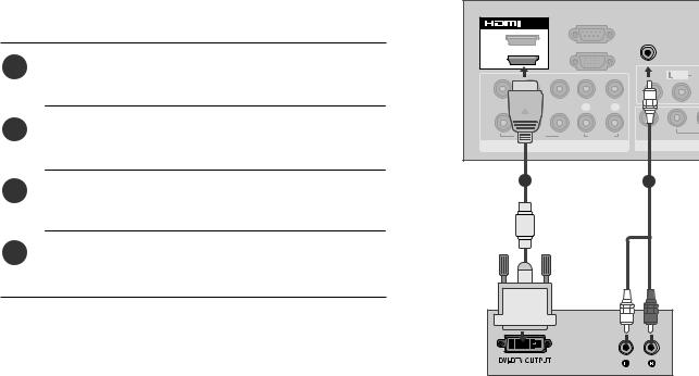
HDMI, the HDMI logo and High-Definition Multimedia Interface are trademarks or registered trademarks of HDMI Licensing LLC.
Only 32/42/47/55SL8***
(Except(55SL8***)55SL8***)
x 8
Bolts for stand |
Cable management |
Protection Cover |
assembly |
clip |
(Refer to p.20) |
|
(Refer to p.23) |
|
(Refer to p.19) |
||
|
(Only 26/32/37/42LH2***, 32/42LF2***,
26/32/37/42LH2***,32/37/42/47LH3***,
26LU5***, 32/37/42LH3***, 37/42LH5***,
37/42/47/55LH5***,32/42LH6***,42/47LH9***
32/42LH6***, 32/37LH7***, 42LH9***)
1-screw for stand fixing (Refer to p.21)
42/47SL9***
|
|
|
|
|
|
|
POWER |
/OFF |
|
|
|
|
|
|
|
|
|
|
|
|
|
|
GY |
|
ON |
|
|
|
|
|
|
ENER |
|
|
|
|
|
|
|
|
|
G |
AV |
|
|
|
|
|
1 |
SAVIN |
|
||
|
|
|
|
|
MODE |
TV |
||
|
|
|
|
4 |
|
2 |
|
INPUT |
|
|
|
T |
7 |
5 |
3 |
|
|
|
|
|
IS |
|
|
|
|
|
|
|
|
L |
8 |
|
6 |
|
|
|
|
|
|
|
|
|||
|
|
|
MARK/ |
0 |
9 |
|
|
|
|
|
|
Q. |
|
|
|
|
|
|
|
|
FAV |
VIEW |
|
|
|
|
MENU |
MUTE |
P |
|
|
|
|
||
|
RATIO |
|
|
|
|
|
||
|
|
|
EG |
|
|
|
|
|
|
|
|
|
AP |
|
|
|
|
|
|
Q. |
|
|
|
|
|
|
|
|
MENU |
|
|
|
|
|
|
OK
OK
RETURN
Cable Holder (Refer to p.23)
TV/INPUT |
x 2 |
Batteries
( )
Wall Mounting Bracket(Separate purchase)
RW120 |
(19/22LH2***, |
19/22LU5***) |
RW230 |
|
|
|
AW-47LG30M |
||||||||
|
|
|
|
|
|
|
|
|
|
|
|
|
|
|
|
|
|
|
|
|
|
|
|
|
|
|
|
|
|
|
|
|
|
|
|
|
|
|
|
|
|
|
|
|
|
|
|
|
|
|
|
|
|
|
|
|
|
|
|
|
|
|
|
|
|
|
|
|
|
|
|
|
|
|
|
|
|
|
|
|
|
|
|
|
|
|
|
|
|
|
|
|
|
|
|
|
|
|
|
|
|
|
|
|
|
|
|
|
|
|
|
|
|
|
|
|
(26/32LH2***, 32LF2*** |
(32/37/42LH2***, 32/42LF2***, |
|
26LU5***, 32LH3***, |
32/37/42/47LH3***, |
|
32LH6***, 32LH7***, |
37/42/47LH5***, 32/42LH6***, |
|
32/37/42/47LH7***, 42/47LH9***, |
||
32SL8***) |
||
|
32/42/47SL8***) |
AW-55LH40M |
(55LH5***, 55SL8***) |
Use screws 12mm(+0.5/-0.5) long on the SET assembly side.(Separate purchase) (Only 42/47LH7***, 42/47SL8***)
|
Set assembly side |
|
Set assembly side |
||||||
|
(with guide spacer) |
(without guide spacer) |
|||||||
|
|
|
|
|
|
|
|
|
|
|
|
|
|
|
|
|
|
|
|
|
|
|
|
|
|
|
|
|
|
12mm |
12mm |
|
Guide spacer |
2

|
RATIO |
Batteries POWER ON/OFF TV |
ENERGYSAVING |
TV |
|
|
SLEEP |
|
POWER |
AV MODE |
AV MODE |
|
|||
Owner’s Manual |
|
|
|
|
|
CD RATIO |
POWER |
|
|
|
|
|
|
|
MARK |
MARK |
|
|
|
|
FAV |
FAV |
|
|
|
|
|
|
or |
LIST |
|
Q.VIEW |
or |
or |
|
|
MUTE |
|
|
||
MENU |
|
RETURN |
|
|
|
|
|
MARK |
|
|
|
|
|
FAV |
|
|
|
|
Q.MENU |
|
|
|
|
Power Cord |
|
|
Remote Control |
|
|
|
|
|
|
|
|
This item is not included for all models( ).
Polishing Cloth
Polishing cloth for use on the screen.
* Lightly wipe any stains or fingerprints on
the surface of the TV with the polishing
cloth.
Do not use excessive force. This may cause scratching or discolouration.
Only 32/37/42/47LH732/42/47LH7***
***
((Only 37/42/437/42/47LH7***)
|
|
|
|
|
|
|
|
|
|
|
|
|
|
|
|
|
|
|
|
|
|
|
|
|
|
|
|
|
|
|
|
|
|
|
|
|
|
|
|
|
|
|
|
|
|
|
|
|
|
|
|
|
|
|
|
|
|
|
|
|
|
|
|
|
|
|
|
|
|
|
|
|
|
|
|
|
|
|
|
|
|
|
|
|
|
|
|
|
|
|
|
|
|
|
|
|
|
|
|
|
|
|
|
|
Cable management clip |
Protection cover |
|
|
|
|
|
|
|
|
|
|
|||||||||
|
Stand rear cover |
Protective Bracket and Bolt for Power Cord |
|
|||||||||||||||||
|
|
|
|
|
|
|
|
|
|
|
|
|
|
|
|
|
|
|
|
|
|
|
|
|
|
|
|
|
|
|
|
|
|
(Refer to p.21) |
|
||||||
|
|
(Refer to p.23) |
|
(Refer to p.20) |
|
|
|
|||||||||||||
|
|
|
|
|
|
|
||||||||||||||
|
|
|
|
|
|
|
|
|
|
|
|
|
|
|
|
|
|
|
(Refer to P.25) |
|
|
|
|
|
|
|
|
|
|
|
|
|
|
|
|
|
|
|
|
||
|
|
|
|
|
|
|
|
|
|
|
|
|
|
|
|
|
|
|
||
|
|
|
|
|
|
|
|
|
|
|
|
|
|
|
|
|||||
|
|
*** |
32LH7*** |
*** 37LH7*** |
|
42LH7*** |
|
47LH7*** |
|
|
||||||||||
|
|
(32LH7 |
only) |
(37LH7 |
only) |
|
(42LH7*** only) |
|
(47LH7*** only) |
|
|
|||||||||
x 7 |
x 8 |
x 3 |
x 4 |
x 8 |
M4x20 |
M4x20 |
M4x20 |
M4x16 |
M4x16 |
bolts for stand assembly (Refer to p. 18)
Only 19/19/22/26LU5***/ 6LU5***
USB extension cable USB
Make sure to use the provided USB extension cable,
( )
Which is specially designed for a slim fit.
Only 19/19/22LH2***2LH2* *
*
|
x 2 |
x 3 |
|
|
|
|
(Only 19/22LU5***) (Only 26LU5***,) |
|
Protection cover |
||
Cable Holder |
Bolts for stand assembly |
Cable management clip |
|||
|
|||||
(Refer to p.22) |
(Refer to p.20) |
||||
(Refer to p.22) |
(Refer to p.17) |
|
|||
|
|
||||
|
|
|
|
||
26/32/326/32/37/42LH2***,32/37/42/47LH3***,/42LH2***, 3 /37/42/47LH3***, |
Only |
37/42 47/5 LH * *, 3 /42LH6***, 42/47LH9*** |
37/42/47/55LH5***,32/42LH6***,42/47LH9*** |
(Except 55LH5***)
or
x 4
Bolts for stand assembly
(Refer to p.18)
Protection cover
(Refer to p.20)
Only 32/32/42LF2****
x 4 |
x 4 |
|
|
|
or |
Bolts for stand assembly |
Protection Cover |
|
(Refer to p.17) |
(Refer to p.20) |
|
3
 CAUTION
( )
19/22/26/32/37/42LH2***,32/37/42/47LH3***
Only 19/22/26LH2***19/22/26LH2*** |
|
|
|
|
|
|
MENU |
|
|
|
|
|
|
INPUT |
OK |
VOLUME |
PROGRAMME |
|
|
|
|
|
|
||||
POWER |
|
|
|
|
|
|
INPUT MENU |
OK |
|
P |
|
|
|
|
|
|
32/37/42LH2*** |
|||
|
|
|
Only 32/37/42LH2***, |
|||
|
|
|
32/37/42/47L32/37/42/47LH3***3 |
* |
||
|
|
|
P |
|
PROGRAMME |
|
|
|
|
|
|
|
|
|
|
|
|
|
VOLUME |
|
|
|
|
OK |
|
OK |
|
|
|
|
MENU |
|
MENU |
|
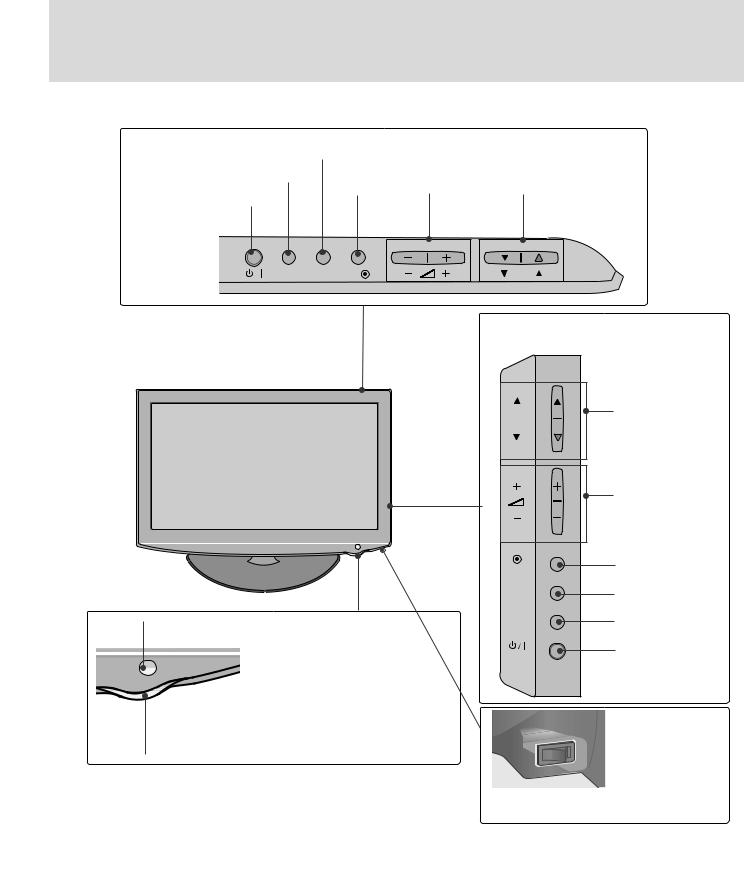
Remote Control Sensor |
|
INPUT |
|
INPUT |
||
|
|
|
|
|
POWER |
|
|
|
|
|
|
|
|
Power/Standby Indicator |
|
|
|
|
|
|
- (standby) |
|
|
|
|
|
|
• Illuminates red in standby mode. |
|
|
|
OFF |
|
|
- |
|
ON |
|
|
||
|
|
|
|
|
||
• Illuminates blue when the TV is switched on. |
|
|
|
Main Power Switch |
||
|
|
|
|
|
||
|
|
|
|
|
( / |
|
|
|
|
Main Power Switch |
) |
||
|
|
|
Except 19/22LH2*** |
* 19/22LH2*** |
||
4

|
|
|||||
19/22/26LU5*** |
|
|
|
|
|
|
Only 19/22/26LU5*** |
|
|
26LU5*** |
|||
|
|
|
|
|
Only 26LU5*** |
|
19/22LU5*** |
|
|
|
|
|
|
Only 19/22LU5*** |
|
|
|
|
|
PROGRAMME |
POWER INPUT |
MENU |
OK |
VOLUME |
PROGRAMME |
||
|
|
|
|
|
P |
|
INPUT MENU |
OK |
|
|
P |
VOLUME |
|
|
|
|
|
|
|
|
|
|
|
|
|
|
OK |
|
|
|
|
|
OK |
|
|
|
|
|
|
|
MENU |
|
|
|
|
|
MENU |
|
|
|
|
|
|
|
INPUT |
|
|
|
|
|
INPUT |
|
|
|
|
|
|
|
POWER |
|
|
|
|
|
|
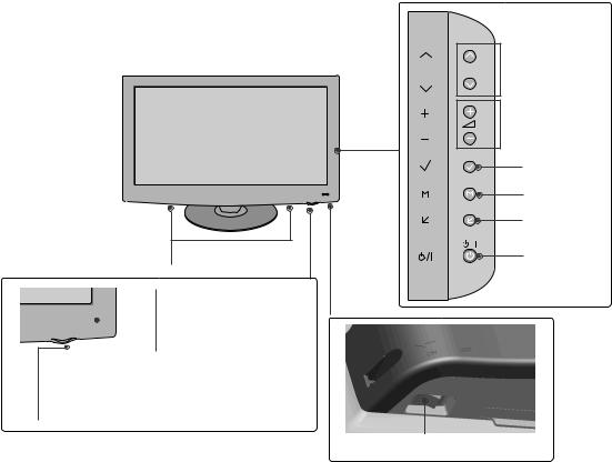
Main Power Switch |
|
|
|
|
|
|
Main |
|
|
|
|
|
ON |
( / |
|
|
|
|
|
|
Power |
|
|
|
|
|
OFF |
Switch |
|
|
) |
||||
|
|
|||||
|
Remote Control Sensor |
|
|
|||
|
|
|
|
|
|
|
Power/Standby Indicator |
|
|
|
|||
- (standby) |
|
|
||||
Illuminates red in standby mode. |
|
|
|
|||
- |
|
|
||||
Illuminates white when the TV is switched on. |
|
|
||||
5

32/42LF2***
Power/Standby Indicator
 •-illuminates red in standby(standby)mo e.
•-illuminates blue when the TV is switched on.
Remote Control Sensor
POWER Button
P |
PROGRAMME |
+
 VOLUME
-
OK
OK
MENU
MENU
INPUT
INPUT
6

37/42/47/55LH5***
Only 37/42/47/55LH5***
Remote Control Sensor
Intelligent Sensor

Adjusts picture according to
thesurrounding conditions.

Power/Standby Indicator
•-Illuminates red in standby(standby)mo e.
•Illuminates blue when the TV is switched on.
 PROGRAMME
P
 VOLUME
OK
OK
MENU
MENU
INPUT
INPUT
POWER
OFF  ON
ON
Main Power Switch
Main Power Switch
( / )
7

Here shown may be somewhat different from your TV.
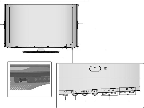
32/37/42/47LH7***
Only 32/37/42/47LH7***
PROGRAMME
P
 VOLUME
|
|
|
OK |
|
|
|
OK |
|
Intelligent Sensor |
|
|
|
Adjusts picture according |
to |
MENU |
|
|
||
|
|
||
|
the surrounding conditions |
|
|
|
|
|
MENU |
|
|
|
|
Moving LED |
|
|
|
LED |
Remote Control Sensor |
|
|
|
|
INPUT |
|
|
|
|
INPUT |
POWER(Touch Sensor)
/
Power/Standby Indicator
• Illuminates red in standby mode.
•-I (standby) |
|
lluminates Whitish when the TV is switched on. |
|
- |
|
Note: You can adjust Power Indicator in the |
|
|
Main Power Switch |
OPTION menu. |
|
OPTION |
Main Power Switch |
|
( / ) |
8
Only 42/47LH942/47LH9***
***
P  PROGRAMME
 VOLUME
OK
OK
MENU
MENU
INPUT
INPUT
SPEAKER |
POWER |
|
|
||
|
Remote Control Sensor
Intelligent Sensor


Adjusts picture according to
the surrounding conditions.
Power/Standby Indicator
•- Illuminates red in standby(standby)mode.
•Illuminates white when the TV is switched on.
Main Power Switch
Main Power Switch
( / )
9
32/42LH6***
Power Indicator(Only( 42LH6***)42LH6***)
•-Illuminates blue when the TV is switched on.
Remote Control Sensor
Intelligent Sensor
Adjusts picture according to the surrounding conditions.
Power/Standby Indicator
- (standby)
• Illuminates red in standby mode.
-
• Illuminates blue when the TV is switched on.
Main Power Switch
Main Power Switch
( / )
POWER INPUT MENU OK |
VOLUME |
PROGRAMME |
10
32/42/47/55SL8*** , 42/47/55SL9***
P  PROGRAMME
VOL  VOLUME
OK
OK
 MENU
MENU
MENU
 INPUT
INPUT
INPUT
 POWER
POWER
( SL9***)
Remote Control |
|
Sensor |
|
- |
Intelligent Sensor |
|
Adjusts picture according |
|
to the surrounding |
- / |
conditions( SL9***). |
OFF  ON
ON
Main Power Switch
Main(Power/Switch
)
(Only 42/47/55SL8***)
ON  OFF
OFF
Main Power Switch
Main Power Switch
( / )
(Only 32SL832SL8***) (
|
|
|
|
|
|
OK |
|
MENU |
|
INPUT |
POWER |
|||||
|
|
PROGRAMME |
VOLUME |
|
|
|
||||||||||
|
|
|
|
|
|
|
|
|
|
|
|
|
|
|
|
|
|
|
|
|
|
|
|
|
|
|
|
|
|
|
|
|
|
|
|
|
P |
|
|
|
|
|
|
|
|
|
|
|
|
|
|
|
|
|
|
|
|
|
OK |
MENU |
INPUT |
||||||
|
|
|
|
|
|
|
||||||||||
|
|
|
|
|
|
|
|
|
|
|
|
|
|
|
|
|
|
|
|
|
|
|
|
|
|
|
|
|
|
|
|
|
|
|
|
|
|
|
|
|
|
|
|
|
|
|
|
|
|
|
Power/Standby Indicator
•-Illuminates red in standby(standby)mode.
•Illuminates blue when the TV is switched on.
11

19/22/26/32/37/42LH2***,32/42LF2***,32/37/42/47LH3***
32/37/42/47LH3***,32/37/42LH23***Only 32/432/42LF2***LF2***
3IN
1
11
2
IN 2

2
8 |
8 |
AV IN2 |
AV IN2 |
19/22LH2*** |
|
|
|
32/37/42/47LH3***,32/37/42LH23*** |
||||
Only 19/22LH2*** |
|
|
|
Only 32/37/42/47LH3***, 32/37/42LH23** |
||||
|
|
|
|
|
||||
2 |
3 |
4 |
5 |
6 |
2 |
3 |
4 |
6 |
|
RS-232C IN |
|
|
|
|
|
RS-232C IN |
|
|
(CONTROL) |
|
|
USB IN |
|
|
(CONTROL) |
|
|
|
|
|
HDMI |
2 |
|
|
|
|
|
|
|
SERVICE ONLY |
|
AUDIO IN |
||
HDMI/DVI IN |
RGB IN (PC) |
|
|
|
|
|
RGB IN (PC) |
(RGB/DVI) |
|
|
AUDIO IN |
HDMI |
|
|
|||
|
|
|
|
1 |
|
|
||
|
|
|
|
(RGB/DVI) |
/DVI IN |
|
|
|
|
|
|
|
|
|
VIDEO |
L/MONO AUDIO |
R |
AV |
|
|
|
|
|
|
|
|
|
|
|
|
|
|
|
IN |
ANTENNA IN |
|
|
|
|
IN1 |
|
|
VIDEO |
L(MONO) AUDIO |
|
|
|
|
|
|
||
|
R |
|
VIDEO |
AUDIO |
|
|
|
|
||
VIDEO |
AUDIO |
|
|
|
|
|
|
|
||
COMPONENT IN |
|
|
|
COMPONENT IN |
|
|
|
ANTENNA |
||
|
OUT |
|
|
|
VARIABLE AUDIO OUT |
|
||||
|
|
|
|
|
|
|
IN |
|||
|
|
VARIABLE AUDIO OUT |
|
|
|
AV OUT |
|
|
|
|
|
|
AV IN |
|
|
|
|
|
|
|
|
|
|
|
|
|
|
|
|
|
|
|
7 |
8 |
|
9 |
10 |
7 |
8 |
|
|
9 |
10 |
Only 26/32/37/42LH20**26/32/37/42LH2*** |
|
|
|
|
Only 32/42LF2***32/42LF2*** |
|
|
|
|
|||
2 |
3 |
4 |
5 |
6 |
|
|
2 |
3 |
4 |
5 |
6 |
|
|
|
RS-232C IN |
USB IN |
|
|
|
|
|
USB IN |
|
|
|
|
|
SERVICE ONLY |
|
|
|
|
RS-232C IN |
|
|
|||
|
|
|
|
|
|
SERVICE ONLY |
|
|
||||
|
(CONTROL) |
|
|
|
|
|
(CONTROL) |
|
|
|||
|
|
|
|
|
|
|
|
|
|
|||
HDMI |
2 |
|
|
|
|
|
|
|
|
|
|
|
HDMI |
|
RGB IN (PC) |
AUDIO IN |
|
|
HDMI/DVI IN |
RGB IN (PC) |
AUDIO IN |
|
|
||
1 |
|
(RGB/DVI) |
|
|
1 |
|
|
|
||||
/DVI IN |
|
|
|
|
|
|
|
(RGB/DVI) |
|
|
||
|
|
|
|
|
IN |
|
|
|
|
|
IN1 |
|
|
|
|
VIDEO L(MONO) AUDIO |
|
|
|
|
|
|
|
||
|
|
|
R |
|
|
|
VIDEO |
L(MONO) |
AUDIO R |
|
||
|
VIDEO |
AUDIO |
|
|
|
|
VIDEO |
AUDIO |
|
|
|
|
|
COMPONENT IN |
|
|
OUT |
ANTENNA |
COMPONENT IN |
|
|
OUT |
ANTENNA |
||
|
|
|
|
|
IN |
|
|
|
|
|
||
|
|
|
VARIABLE AUDIO OUT |
|
|
|
|
VARIABLE AUDIO OUT |
IN |
|||
|
|
|
|
AV |
|
|
|
|
|
AV |
|
|
|
7 |
|
8 |
|
9 |
10 |
7 |
|
8 |
|
9 |
10 |
12

|
11 |
Here shown may be somewhat different from your TV.
Only 19/22/26LU5***,19/22/26LU5***,37/42/47/55LH5***,42/47LH9***37/42/47/ LH5***, 2/47LH9***
|
|
|
Only 26LU5*** |
|
|
||
|
|
|
26LU5*** |
|
|
||
|
|
|
IN 3 |
2 |
|
|
|
|
|
|
|
|
1 |
|
|
ON |
|
|
|
|
|
|
|
OFF |
|
|
|
|
|
|
|
|
|
|
|
8 |
|
|
|
1 |
|
|
|
|
|
|
|
|
|
|
AV IN2 |
|
|
|
|
19/22/26LU5*** |
|
|
|
|
|
||
Only 19/22/26LU5*** |
|
|
26LU5*** |
|
|||
|
|
|
|
Only 26LU5*** |
2 |
3 |
|
2 |
3 |
4 |
5 |
6 |
|||
|
|
||||||
|
RS-232C IN |
|
USB IN |
|
|
RS-232C IN |
|
|
(CONTROL) |
|
SERVICE ONLY |
|
|
||
HDMI/DVI IN |
|
|
/DVI IN |
(CONTROL) |
|||
|
|
|
|
||||
2 |
RGB IN (PC) |
|
|
|
2 |
|
|
|
|
|
|
|
|||
|
|
AUDIO IN |
|
|
RGB IN (PC) |
||
|
|
|
|
|
|||
1(DVI) |
|
|
|
|
|
||
|
|
(RGB/DVI) |
|
1(DVI) |
|
||
|
|
|
|
|
|||
|
VIDEO |
L(MONO) AUDIO |
R |
IN1AV |
|
|
|
|
|
INAV |
2 |
|
|
|
|
|
|
|
|
|
VIDEO |
AUDIO |
|
|
|
1 |
|
COMPONENT IN |
|
|
|
|
||
|
|
|
VIDEO |
AUDIO |
||
|
|
VARIABLE AUDIO OUT |
ANTENNA |
|||
|
|
AV OUT |
|
COMPONENT IN |
|
|
|
|
|
IN |
|
|
|
7 |
8 |
|
9 |
10 |
7 |
|
IN 3
AV IN2
46
AUDIO IN (RGB/DVI)
VIDEO |
L/MONO |
AUDIO |
R |
|
|
|
IN1AV |
VARIABLE AUDIO OUT
AV OUT
89
2
8
ANTENNA
IN
10
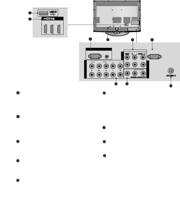
1 Power Cord Socket
This TV operates on an AC power. The voltage isindicated on the Specifications page. Never
attempt to operate the TV on DC power.
2 HDMI Input
Connect a HDMI signal to HDMI IN. HDMI
Or DVI(VIDEO)signal to HDMI/DVI port with DVI
(HDMI ) to HDMI cable.
3 RS-232C IN PORT
Connect to the RS-232C port on a PC.
RS-232C ( )
This port is used for Service or Hotel mode.
7 Component Input
Connect a component video/audio device to
thesejacks.
8 Audio/Video Input
Connect audio/video output from an external
deviceto these jacks.
9 AV Output
Connect second TV or monitor to the AV OUT
socketon the TV.
Variable Audio Output
Connect an external amplifier or add a subwoofer
to your surround sound system.
4 |
RGB IN Input |
|
Antenna Input |
|
Connect the output from a PC. |
10 |
|
|
RGB |
||
|
|
|
Connect RF antenna to this jack. |
|
|
|
( , , |
5 |
SERVICE ONLY PORT |
|
) |
|
|
11 |
USB IN Input |
6 |
RGB/DVI Audio Input |
|
Connect USB storage device to this jack. |
|
Connect the audio from a PC. |
|
USB |
|
RGB/DVI |
|
|
|
|
|
13 |

32/42LH6***
|
|
|
|
|
|
9 |
|
|
|
|
|
|
IN 3 |
1 |
|
|
|
|
|
2 |
|
|
|
|
|
|
|
2 |
3 |
4 |
|
|
|
|
/DVI IN |
|
|
|
|
|
|
2 |
|
AUDIO IN |
|
|
|
|
RGB IN (PC) |
|
(RGB/DVI) |
|
|
|
|
1(DVI) |
|
|
|
|
|
6 |
|
|
VIDEO |
|
|
|
|
|
|
L/MONO |
AUDIO |
R |
AV |
|
2 |
|
|
|
|
|
|
|
|
|
|
|
IN1 |
|
|
|
|
|
|
|
1 |
|
|
|
|
|
VIDEO |
AUDIO |
|
VARIABLE AUDIO OUT |
ANTENNA |
AV IN2 |
COMPONENT IN |
|
|
AV OUT |
IN |
|
5 |
|
6 |
7 |
8 |
|
1 Power Cord Socket |
6 Audio/Video Input |
This TV operates on an AC power. The voltage is |
Connect audio/video output from an external |
|
|
|
device to these jacks. |
indicated on the Specifications page. Never |
|
attempt to operate the TV on DC power. |
|
2 HDMI Input
Connect a HDMI signal to HDMI IN.
HDMI
Or DVI(VIDEO)signal to HDMI/DVI port with DVI
(HDMI ) to HDMI cable.
3 RGB IN Input
7 AV Output
Connect second TV or monitor to the AV OUT
socketon the TV.
Variable Audio Output
Connect an external amplifier or add a subwoofer
toyour surround sound system.
RGB |
||
Connect the output from a PC. |
8 |
Antenna Input |
( , ,
Connect RF antenna to this jack.
4 RGB/DVI Audio Input
)
Connect the audio from a PC. RGB/DVI 9
5 Component Input
Connect a component video/audio device to
thesejacks.
USB IN Input
Connect USB storageUSBdevice to this jack.
14
32/37/42/47LH7***
Only 32/37/42/47LH7***
8
9 |
|
/DVI IN |
3 |
2 |
1(DVI) |
2 |
1 |
3 |
4 |
|
RGB IN
|
RGB IN (PC) |
AUDIO IN |
|
|
(RGB/DVI) |
COMPONENT |
VIDEO |
|
2 |
|
|
|
|
|
IN |
1 |
|
|
|
|
|
|
|
RS-232C IN |
AV |
VIDEO |
L/MONO AUDIO |
R |
(CONTROL) |
|
||||
IN2 |
|
|
|
|
AUDIO |
|
|
|
IN1 AV |
|
|
|
|
|
|
|
VARIABLE AUDIO OUT |
OUT AV |
|
|
|
|
||
56
ANTENNA IN
7
1 Power Cord Socket
This TV operates on an AC power. The voltage isindicated on the Specifications page. Never
attempt to operate the TV on DC power.
2 RGB IN Input
6 AV Output
Connect second TV or monitor to the AV OUT
socketon the TV.
Variable Audio Output
Connect an external amplifier or add a subwoofer
toyour surround sound system.
RGB
Connect the output from a PC.
RGB/DVI Audio Input
Connect the audio from a PC. RGB/DVI
7 Antenna Input
( , ,
Connect RF antenna to this jack.
)
3 Audio/Video Input
Connect audio/video output from an external
deviceto these jacks.
8 USB IN Input
Connect USB storage device to this jack.
USB
4 RS-232C IN PORT
Connect to RSthe-232CRS-232C port on a PC.
( )
This port is used for Service or Hotel mode.
5 Component Input
Connect a component video/audio device to
thesejacks.
9 HDMI Input
Connect a HDMI signal to HDMI IN.
HDMI
(Or DVI(VIDEO)signalHDMI )to HDMI/DVI port with DVI to HDMI cable.
15

32/42/47/55SL8***
1 |
2 |
3 |
4 |
5 |
|
9 |
|
R |
3 |
|
AUDIO |
IN |
|
L/MONO |
2 |
|
4 |
||
|
||
VIDEO |
|
|
AV IN 2 |
|
IN |
/DVI IN |
|
RGB IN (PC) |
AUDIO IN |
|
CAUTION ( 42/47SL9***) |
|
|
(RGB/DVI) |
||||||
|
|
|
|
||||
2 |
|
1 |
AV IN 1 |
|
|
USB |
|
|
|
|
|
|
|
G Use a product with the following thickness |
|
2 |
|
|
|
|
|
for optimal connection to HDMI cable(only |
|
|
|
|
|
|
A |
10 |
|
|
|
|
|
|
|
HDMI IN 3) / USB device. |
|
|
|
|
VIDEO L/MONO |
AUDIO R |
|
*A |
10mm |
|
|
|
|
|
|
||
1 |
|
|
|
|
|
|
|
VIDEO |
|
AUDIO |
VARIABLE AUDIO OUT |
ANTENNA |
|
|
|
COMPONENT IN |
|
AV OUT |
IN |
|
|
||
|
|
6 |
7 |
|
8 |
|
|
1 Power Cord Socket
This TV operates on an AC power. The voltage isindicated on the Specifications page. Never
attempt to operate the TV on DC power.
6 Component Input
Connect a component video/audio device to
thesejacks.
2 HDMI IN Input
Connect a HDMI signal to HDMI IN. Or DVI (VIDEO)
HDMI signal to HDMI/DVI port with DVI to HDMI cable.
(HDMI )
7 AV Output
Connect second TV or monitor to the AV OUT
socketon the TV.
Variable Audio Output
Connect an external amplifier or add a subwoofer
3 RGB IN Input to your surround sound system.
Connect the output from a PC. RGB
4 Audio/Video Input
Connect audio/video output from an external
deviceto these jacks.
5 RGB/DVI Audio Input
Connect the audio from a PC or DTV. RGB/DVI
8 Antenna Input
( , ,
Connect RF antenna to this jack.
)
9 USB IN Input
Connect USB storage device to this jack.
USB
16

19/22LH2*** |
|
|
|
32/42LF2*** |
|
Only 19/22LH2*** |
|
Only 32/42LF2*** |
|
|
|
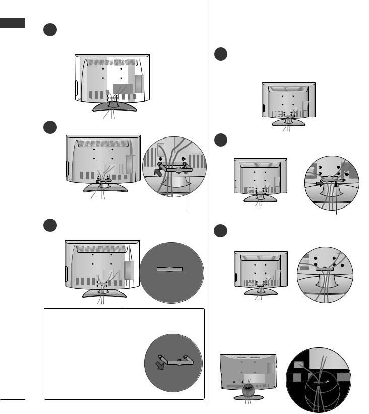
1 1 Carefully place the TV screen side down on a Carefully place the TV screen side down on a cush-
ionedsurface to protect the screen from damage. cushioned surface to protect the screen from
damage.
2
2 Assemble the TV as shown.
|
|
|
|
3 |
|
|
|
|
|
|
|
|
||
|
Cover Base |
|||
Only 19/22/26LU519/22/26LU5***
***
Assemble the parts of the Stand Body with the Stand Base of the TV.

 Stand Body
 Stand Base
Assemble the TV as shown.
1 
Carefully place the TV screen side down on a cush-
ioned surface to protect the screen from damage.
Fix the 4 bolts securely using the holes in the
4 4
2 Fix the 2 or 3 bolts2 securely3 using the holes as back of the TV.
shown.
(Only 26LU5***)
17

26/32/37/42LH2***, |
32/37/42/47LH7*** |
|
|||
Only 26/32/37/42LH2***, |
Only 32/37/42/47LH7*** |
|
|||
32/37/42/47LH3***, |
1 ioned surface to protect the screen from damage. |
||||
32/37/42/47LH3***, |
|||||
37/42/47LH5*** ,***32/42LH6*** |
***, |
Carefully place the TV screen side down on a cush- |
|||
7/42/47LH5 , 32/42LH6 |
|
|
|||
|
|
|
|
||
42/47LH9*** |
|
|
|
|
|
42/47LH9*** |
|
|
|
|
|
1 |
Carefully place the TV screen side down on a cushioned |
|
|
||
|
|
|
|||
|
surface to protect the screen from damage. |
|
|
|
|
|
|
2 |
Assemble the parts of the Stand Body with |
||
|
|
|
|
||
2 |
|
the Stand Base of the TV. |
|
|
|
|
|
|
|||
|
Assemble the TV as shown. |
|
32LH7*** |
47LH7*** |
37LH7*** |
|
|
|
|||
|
|
|
Stand Body |
|
|
|
|
M4x20 |
M4x16 |
M4x20 |
|
|
|
|
Stand Base |
|
|
|
|
|
42LH7*** |
|
|
|
|
|
|
M4x20 |
|
3 |
Fix the 4 bolts securely using the holes in the |
|
Stand Body |
||
|
|
|
|||
4 |
|
|
|||
|
back of the TV. |
|
|
|
|
|
|
|
|
Stand Base |
|
|
|
3 Assemble the TV as shown. |
|||
4 Fix the 4 bolts securely4 using the holes in the back of the TV.
32/37LH7*** |
42/47LH7*** |
M4x20 |
M4x16 |
18

|
|
Image shown may differ from your TV. |
NOT USING THE DESK-TYPE |
STAND |
|
|
|
Only 32/42/47SL8*** |
19/22LH2*** |
32/42/47SL8*** , 42/47SL9*** |
Here shown may be somewhat different from your TV. |
When installing the wall-mounted unit, use the pro- |
|
|
|
|
tection cover. |
|
|
Carefully place the TV screen side down on a cush- |
|
1 |
|
ioned surface to protect the screen from damage. |
Only 19/22LH2*** |
|
|
|
Carefully place the TV screen side down on a cush- |
|
1 |
|
ioned surface to protect the screen from damage. |
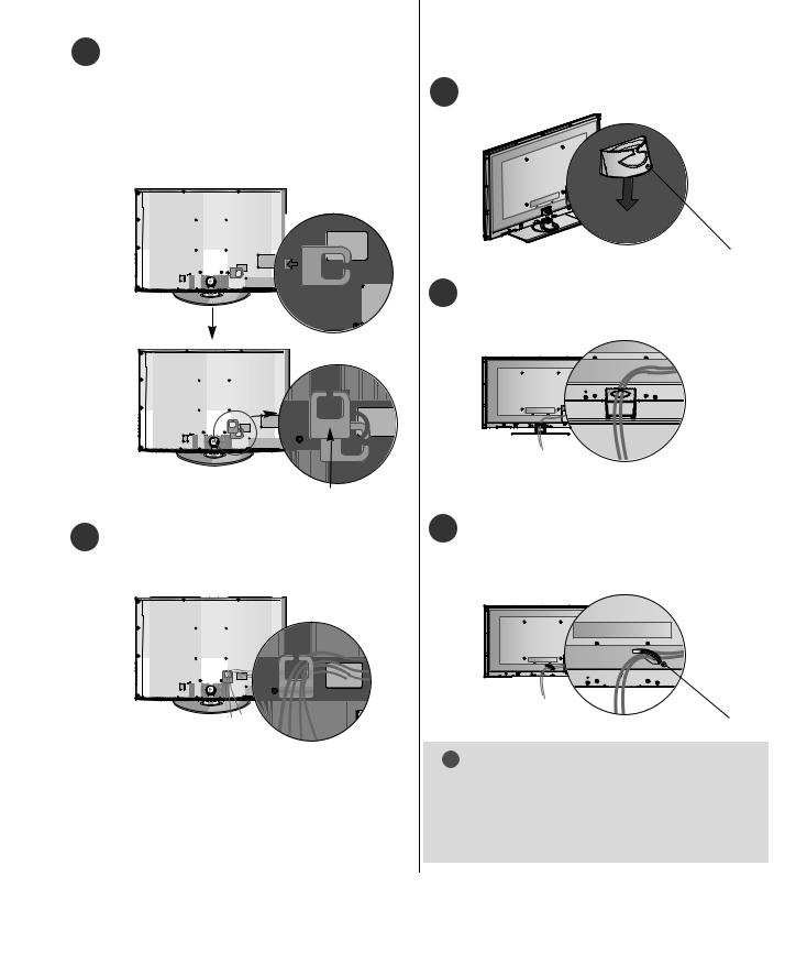
2 Assemble the parts of the Stand Body with the Stand Base of the TV.
Stand Body |
42/47SL9*** |
|
Body Stand Body |
Stand Base 20mm |
|
|
Stand Base |
3
Assemble the TV as shown.


 42/47SL9***
2
3
4
Loose the bolts from TV.
Detach the Stand Body from T V.
Insert theProtectionctiCovern Cover into the TV.
4 Fix the 4 bolts securely4 using the holes in the back of the TV.
Protection Cover
5 Fix the 4 bolts securely using the holes in the
4 back of the TV.
42/47SL9***
16mm
19

Only 32/42LF32/42/LF2******
|
42/47LH9*** |
PROTECTION |
Only 42/47LH9*** |
After removing the protection paper from the pro- |
|
Insert the |
|
COVEROTECTION |
|
P |
tection cover, adhere it to the TV as shown. |
COVER into the TV |
|
|
|
until clicking sound. |
|
Only 26/32/37/42LH2***,26/32/37/42LH2***, 32/37/42/47LH3***,37/42/47/55LH5***/42/47LH3 *, 37/42/47/55LH5***, 32/42LH6*****
|
32/42/47/55SL8*** |
|
Only 32/42/47/5 SL8* |
Insert thePROTECROTIONECTICOVERNCOVER into the TV |
|
|
|
until clicking sound. |
|
|
Insert the PROTECTION |
32/37/42/47LH7*** |
PROTECTION COVER |
PROTECTION COVER |
|
Only 32/37/4 /47LH7*** |
COVER into the TV until |
clicking sound. |
|
|
|
PROTECTION COVER
removing the protection paperthe protection cover, adhere it
TV as shown.
20
( ) TO USE THE STAND REAR |
|
ATTACHING THE TV TO A |
|
DESK |
37/42/47LH7*** |
Here shown may be somewhat different from your TV. |
|
COVER (37/42/47LH7*** only) |
|
|
|
The TV must be attached to desk so it cannot be pulled |
Here shown may be somewhat different from your TV. |
in a forward/backward direction, potentially causing |
Install the STAND REAR COVER as shown. |
injury or damaging the product. Use only an attached |
Protection Cover |
26/32/37/42LH2***, |
|
screw. |
|
32/42LF2***, 32/37/42/47LH3***, |
|
Only 26/32/37/42LH2 |
|
37/42/LH5***,32/42LH6******, |
|
32/42LF2***, 32/37/42LH3***, |
|
32/37LH7***,42LH9*** |
|
26LU5***, 37/42LH5***, |
|
32/42LH6***, 32/37LH7***, |
|
42LH9*** |
|
1-Screw (provided1 as( )parts of the product)
Stand
Desk
! WARNING
STAND REAR COVER
Grip the knob in your fingers and pull it.
POSITIONING YOUR DISPLAY
G To prevent TV from falling over, the TV should |
( 19/22LH2***) |
be securely attached to the floor/wall per installa- |
|
|
|
|
Only 19/22LH2***) |
|
|
tion instructions. Tipping, shaking, or rocking the |
Here shown may be somewhat different from your TV. |
machine may cause injury. |
|
|
|
|
Adjust the position of the panel in various ways for |
|
|
SWIVEL STAND
Swivel Stand
(Except( 19/22/26LU519/22/26LU5***,***, 19/219/22LH2***)LH2***
This feature is not available for all models.
After installing the TV, you can adjust the TV manually to the left or right direction(by2020)degrees to suit your
viewing position.
maximum comfort.
• Tilt range
12
0
0 |
3 |
! NOTE
GThe following model is a fixed stand type model-19/22/26LU5( )without the Tilt and Swivel features so excessive pressure may damage the set.
- 19/22/26LU5***
21
PREPARATION
|
Only 19/22/26/32/37/42LH2***, |
||||||||||||||
Here shown may be somewhat different from your TV. |
19/22/26/32/37/42LH2***, |
||||||||||||||
|
|
|
|
|
|
|
|
|
|
|
|
|
|||
|
|
|
|
|
|
|
|
|
|
|
|
|
|||
Only 19/22LH2*** |
32/42LF2***, 32/37/42/47LH3***, |
||||||||||||||
32/42LF2***, 32/37/42/47LH3***, |
|||||||||||||||
19/22LH2*** |
37/42/47/55LH5***,32/42LH6***, |
||||||||||||||
|
Connect the cables as necessary. |
||||||||||||||
|
|
|
|
|
|
|
|
|
|
|
|
|
37/42/47/55LH5***, 32/42LH6***, |
||
1 |
|||||||||||||||
|
|
42/47LH9*** |
|||||||||||||
|
To connect additional equipment, see the |
42/47LH9*** |
|||||||||||||
|
“ ” |
|
|
|
|||||||||||
|
EXTERNAL EQUIPMENT SETUP section. |
|
|
|
|||||||||||
|
|
|
|
|
|
|
|
|
|
|
|
|
1 |
Connect the cables as necessary. |
|
|
|
|
|
|
|
|
|
|
|
|
|
|
|||
|
|
|
|
|
|
|
|
|
|
|
|
|
|
To connect additional equipment, see the |
|
|
|
|
|
|
|
|
|
|
|
|
|
|
|||
|
|
|
|
|
|
|
|
|
|
|
|
|
|
“ ” |
|
|
|
|
|
|
|
|
|
|
|
|
|
|
|
External Equipment Setup section of the manual. |
|
|
|
|
|
|
|
|
|
|
|
|
|
|
|
|
|
|
|
|
|
|
|
|
|
|
|
|
|
|
|
|
|
|
|
|
|
|
|
|
|
|
|
|
|
|
|
|
|
|
|
|
|
|
|
|
|
|
|
|
|
|
|
|
|
|
|
|
|
|
|
|
|
|
|
|
|
|
|
|
|
|
|
|
|
|
|
|
|
|
|
|
|
|
|
|
|
|
|
|
|
|
|
|
|
|
|
|
|
|
|
|
|
2 Install the“CABLECABLEMANAGEMENTNAGEMENTCLIP”CLIP as shown.
2 Open the“CABLEABLMANAGEMENTMANAGEMENTCLIP” CLIP as shown and manage the cables.
|
CABLE MANAGEMENT CLIP |
|
|
3 |
“CABLE MANAGEMENT CLIP” |
|
CABLE MANAGEMENT CLIP |
|
Fit the CABLE MANAGEMENT CLIP as shown. |
“CABLE MANAGEMENT CLIP” |
|
|
3 |
||
|
|
Fit the |
ABL MANAGEMENT CLIP as |
|
|
shown. |
|
How to remove the CABLE MANAGE- |
19/22/26LU5*** |
|
|
Only 19/22/ 6LU5*** |
|
“CABEL MANAGEMENT CLIP”*** |
After Connecting the cables as necessary, install |
|
MENT CLIP(Only 19/22LH2 ) |
|
|
( 19/22LH2***) |
||
CABLE HOLDER as shown and bundle the cables. |
||
G Hold the CABLE MANAGE- |
||
MENT CLIP with both hands |
|
|
|
|
|
and pull it backward. |
|
|
|
|
2222
32/37/42/47LH7***
Only 32/37/42/47LH7***
Align the hole with the tab on the CABLE
1 CABLE MANAGEMENTMANAGEMENT CLIP.
Turn the CABLE MANAGEMENT CLIP as
shown. CABLE MANAGEMENT
Note : that excessive force might cause damage to the product when using Cable Management clip.
Only 32/42/47/532/42/47/55SL8***,42/47SL9***SL8* *
FOR DESK-TYPE STAND
1 Install “CABLEthe CABLEMANAGEMENTMANAGEMENTCLIP” CLIP as shown.
CABLE MANAGEMENT CLIP
2Connect the cables as necessary. To connectadditional equipment, see the EXTERNAL
“ ”EQUIPMENT SETUP section.
FOR WALL MOUNT
CABLE MANAGEMENT CLIP
2 Connect the cables as necessary. 1
To connect additional equipment, see the
“ ”External equipment Setup section.
After Connecting the cables as necessary,
installCABLE HOLDER as shown and bundle
“ ”
the cables. To connect additional equipment,
CABLE HOLDER
see the External equipment Setup section.
CABLE HOLDER
! NOTE
G Do not use the CABLE MANAGEMENT CLIPCABLEto MANAGMENT CLIPlift the TV.
-If the TV is dropped, you may be injured or the TV may be damaged.
23

KENSINGTONSECURITYSYSTEM
KENSINGTONThis feature is not available for all models.
Here shown may be somewhat different from your TV.
Here shown may be somewhat different from your TV.
The TV is equipped with a Kensington Security System connector on the back panel. Connect the
1 Carefully place the TV screen side down on a cushKensington SecurityKENSINGTONSystem cable as shown below.
ioned surface to protect the screen from damage. For the detailed installation and use of the
KENSINGTON
Kensington Security System, refer to the user’s guide provided with the Kensington Security System.
For further information, contact http://wwwKENSINGTON.kensing-
ton.com, the internet homepage of the Kensington
KENSINGTON WWW. company. Kensington sells security systems for expensiveKENSINGRONelectronic.COM equipment such as notebook
PCs and LCD projectors.
2
3
4
NOTE |
|
||
Loose the bolts and then detach the stand from |
|
|
|
TV. |
KENSINGTON |
||
|
- The Kensington Security System is an optional accessory. |
||
|
KENSINGTON |
|
|
|
NOTES |
|
|
|
a. If the TV feels cold to the touch, there may be a |
||
|
!smallNOTE“flicker” when when it is turned on. |
|
|
|
This is normal, there is nothing wrong with TV. |
||
|
|
||
|
b. Some minute dot defects may be visible on the |
||
|
|
||
|
screen, appearing as tiny red, green, or blue spots. |
||
|
However, they have no adverse effect on the moni- |
||
|
|
|
|
(Only 26LU5***) |
tor's performance. |
|
|
(dot defect) |
|||
|
c. Avoid touching the LCD screen or holding your finger(s) |
||
against it for long periods of time. |
|
||
Loose the bolts and then detach the Cover |
|
|
|
Base from T V. |
|
||
Doing so may produce some temporary distortion |
|||
|
|||
|
effects on the screen. |
|
|
|
|
||
|
|
||
|
|
|
|
Cover Base
(Only 26LU5***26LU5***)
Detach the Stand Body from T V.
Stand Body
24

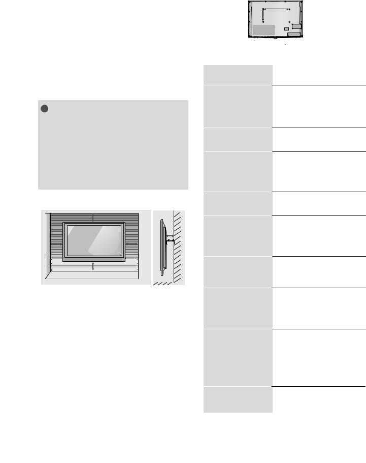
CAREFUL INSTALLATION ADVICE How to secure the power cable
(Only 32/37/42/47LH732/37/42/47LH7***))
***
A You should purchase necessary components to fix the TV
safety and secure to the wall on the market. |
PROTECTIVE BRACKET |
|
|
Secure the power cable with the |
PROTECTIVE BRACKET |
|
|
|
A Position the TV close to the wall to avoid the possibility |
and the bolt as shown. It will help prevent the power cable |
|
|
||
|
||
of it falling when pushed. |
from being removed by accident. |
|
|
Bolt |
|
|
|
|
A The instructions shown below are a safer way to set up |
|
|
the TV, by fixing it to the wall, avoiding the possibility of |
|
|
|
|
|
it falling forwards if pulled. This will prevent the TV from falling forward and causing injury. This will also prevent the TV from damage. Ensure that children do not climb or hang from the TV.
1 |
|
1 |
|
|
PROTECTIVE BRACKET |
|
2 |
2 |
|
|
|
|
|
|
|
|
|
|
|
|
|
|
A |
The TV can be installed in various ways such as on |
||||||
|
|
|
|
|
|
|
|
|
|
|
|
||||||||
|
|
|
|
|
|
|
|
|
|
|
|
|
|
||||||
|
|
|
|
|
|
|
|
|
|
|
|
|
a wall, or on a desktop etc. |
||||||
|
|
|
|
|
|
|
|
|
|
|
|
|
|||||||
1 |
|
|
|
|
|
|
|
|
|
|
|
|
|
The TV is designed to be mounted horizontally. |
|||||
|
|||||||||||||||||||
|
Use the eye-bolts or TV brackets/bolts to fix the |
A |
|
|
|
|
|
|
|||||||||||
|
(product to the wall as shown2 in the picture). |
|
|
|
|
|
|
||||||||||||
|
bolts.) |
|
|
|
|||||||||||||||
|
(If your TV has bolts in the eyebolts, loosen then |
|
EARTHING |
|
|||||||||||||||
|
|
|
|
|
|
|
|
|
|
|
|
|
|
||||||
|
* Insert the eye-bolts or TV brackets/bolts and tight- |
|
Ensure that you connect the earth wire to prevent |
|
|||||||||||||||
|
|
|
|
||||||||||||||||
|
en them securely in the upper holes. |
|
possible electric shock. If grounding methods are not |
|
|||||||||||||||
|
|
possible, have a qualified electrician install a separate |
|
||||||||||||||||
|
|
|
|
|
|
|
|
|
|
|
|
|
|
|
|||||
|
|
|
|
|
|
|
|
|
|
|
|
|
circuit breaker. |
|
|||||
|
|
|
|
|
|
|
|
|
|
|
|
|
|
|
|||||
2 |
|
|
Do not try to earth the TV by connecting it to tele- |
|
|||||||||||||||
|
|
|
|||||||||||||||||
|
Secure the wall brackets with the bolts on the wall. |
|
phone wires, lightening rods or gas pipes. |
||||||||||||||||
|
Match the height of the bracket that is mounted on |
|
|||||||||||||||||
|
|
|
|
|
|
|
|
|
|||||||||||
|
the wall. |
|
|
|
|
|
|
|
|
||||||||||
|
|
|
|
|
|
|
|
|
|
|
|
|
|
|
|
|
|
|
|
|
|
|
|
|
|
|
|
|
|
|
|
|
|
|
|
Power Supply |
|
|
|
|
|
|
|
|
|
|
|
|
|
|
|
|
|
|
|
|
|
||
|
3 |
|
|
|
|
|
|
|
|
|
|
|
|
|
|||||
|
|
|
|
|
|
|
|
|
|
|
|
|
|
||||||
|
|
|
|
|
|
|
|
|
|
|
|
|
|
|
|
Circuit breaker |
|
|
|
|
|
|
|
|
|
|
|
|
|
|
|
|
|
|
|
|
|
|
|
DESKTOPPEDESTALINSTALLATION
3 ( )Use a sturdy rope to tie the product for alignment. Itis safer to tie the rope so it becomes horizontal For adequate ventilation allow a clearance of 4”(10cm)4all around(10the.)TV.
between the wall and the product.
! |
NOTE |
4 inches |
|
|
|
||
G |
When moving the TV undo the cords first. |
|
4 inches |
|
4 inches |
4 inches |
|
|
|
|
|
|
|
|
|
G Use a platform or cabinet strong and large enough |
|
|
|
to support the size and weight of the TV.
G To use the TV safely make sure that the height of the
bracket on the wall and on the TV is the same.
25
:
A |
B |
|
|
Model |
VESA Standard |
Quantity |
|||||||
|
|
(A * B) |
Screw |
|
|||||||
VESA |
47SL9*** |
200 |
* |
200 |
M6 |
4 |
|||||
|
200 |
|
M6 |
4 |
|||||||
|
42SL9*** |
* 200 |
|||||||||
|
|
|
|
|
|
||||||
|
|
|
|
|
|
55SL8*** |
400 |
* 400 |
M6 |
4 |
|
|
|
|
|
|
|
47SL8*** |
200 |
* 200 |
M6 |
4 |
|
|
|
! NOTE |
|
|
|
||||||
|
|
|
|
|
42SL8*** |
200 |
* |
200 |
M6 |
4 |
|
|
|
|
|
32SL8*** |
|
|
|
||||
|
|
|
200 * 100 |
M4 |
4 |
||||||
|
|
|
|
|
|||||||
|
|
47LH9*** |
200 |
* 200 |
M6 |
4 |
|||||
|
|
42LH9*** |
200 |
* 200 |
M6 |
4 |
|||||
|
|
|
|
|
|
|
|||||
|
|
VESA |
47LH7*** |
200 |
* 200 |
M6 |
4 |
||||
|
|
|
42LH7*** |
200 |
* 200 |
M6 |
4 |
||||
|
|
|
37LH7*** |
200 |
* 200 |
M6 |
4 |
||||
|
|
|
|
|
|
32LH7*** |
200 * 100 |
M4 |
4 |
||
|
|
|
|
|
|
42LH6*** |
200 |
* 200 |
M6 |
4 |
|
|
|
|
|
|
|
32LH6*** |
200 * 100 |
M4 |
4 |
||
|
4 inches |
|
4 inches |
|
|
|
|
|
|
|
|
|
|
|
|
|
55LH5*** |
400 * 400 |
M6 |
4 |
4 inches |
|
4 inches |
47LH5*** |
200 * 200 |
M6 |
4 |
|
42LH5*** |
200 * 200 |
M6 |
4 |
||
|
|
|
||||
|
|
|
37LH5*** |
200 * 200 |
M6 |
4 |
|
|
|
|
|
|
|
26LU5*** |
200 * 100 |
M4 |
4 |
|
|
|
|
|
|
|
|
|||||
|
4 inches |
|
|
|
|
||||||
|
|
|
|
|
|
|
22LU5*** |
100 |
* 100 |
M4 |
4 |
|
|
|
|
|
|
||||||
|
|
|
|
|
|
|
19LU5*** |
|
|
||
|
|
|
|
|
|
|
100 |
* 100 |
M4 |
4 |
|
|
|
|
|
|
|
||||||
|
|
|
|
|
|
|
47LH3*** |
200 |
* 200 |
M6 |
4 |
|
|
|
|
|
|
|
42LH3*** |
200 |
* 200 |
M6 |
4 |
|
|
|
|
|
|
|
37LH3*** |
200 |
* 200 |
M6 |
4 |
|
|
|
|
|
|
|
32LH3*** |
200 * 100 |
M4 |
4 |
|
|
|
|
|
|
|
|
42LH2*** |
200 |
* 200 |
M6 |
4 |
|
|
|
|
|
|
|
37LH2*** |
200 |
* 200 |
M6 |
4 |
|
|
|
|
|
|
|
32LH2*** |
200 * 100 |
M4 |
4 |
|
|
|
|
|
|
|
|
26LH2*** |
200 * 100 |
M4 |
4 |
|
|
|
|
|
|
|
|
22LH2*** |
100 |
* 100 |
M4 |
4 |
|
|
|
|
|
|
|
19LH2*** |
100 |
* 100 |
M4 |
4 |
|
|
|
|
|
|
|
42LF2*** |
200 |
* 200 |
M6 |
4 |
|
|
|
|
|
|
|
32LF2*** |
200 * 100 |
M4 |
4 |
|
26
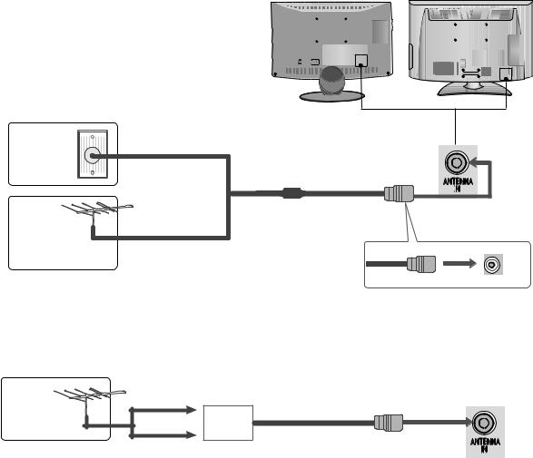
Wall
Antenna
Socket
Outdoor
Antenna
((VHF,UHF)UHF)
Antenna
/ /Multi-family Dwellings/Apartments
( )(Connect to wall antenna socket)
ANTENNA
IN
RF Coaxial Wire (75ohm))
/ /Single-family Dwellings /Houses
(Connect to wall jack for outdoor antenna)
UHF
|
Signal |
|
Amplifier |
|
ANTENNA |
VHF |
IN |
2
27

( 37/42/55LH5***)
(HD
, STB (Set-top Box) ,
(component)
1 |
Connect the video outputs (Y, PB, PR) of the digital set |
|
|
|
||
(Y,Pb,Pr) |
|
|
|
|||
|
top box to the |
OMP |
NENT IN VIDEO jacks on the |
2 |
|
|
|
COMPONENT IN VIDEO |
|
|
|||
|
TV. |
|
|
|
|
|
2 |
|
|
|
1 |
|
|
Connect the audio output(AudioofL,R)the digital set-top box to |
VIDEO |
AUDIO |
||||
|
COMPONENT IN AUDIO |
|
||||
|
|
COMPONENT IN |
|
|||
|
the COMPONENT IN AUDIO jacks on the TV. |
|
|
|||
3
Turn on the digital set-top box.
( )
(Refer to the owner’s manual for the digital set-top box.)
4 |
Select |
omponent1 input source using the INPUT |
|
|
Component 1 INPUT |
|
|
||
|
button on the remote control. |
|
|
|
|
COMPONENT IN 2 Component 2 |
1 |
2 |
|
If connected to COMPONENT IN 2, select
Component2 input source.
|
|
|
|
|
|
|
|
|
|
|
|
|
|
|
|
|
|
|
|
|
|
|
|
|
|
|
|
|
|
|
|
|
|
|
|
|
|
|
|
|
|
|
|
|
Signal |
Component |
HDMI |
|
|
|
|
|
|
|
|
|
|
|
|
|
|
|
|
|
|
|
|
|
|
|
|
|
|
|
|
|
X |
|
|
|
|
|
|
|
|
|
|
|
|
480i/576i |
O |
|
|
|
|
|
|
|
|
|
|
|
||
480p/576p |
O |
O |
|
|
|
|
|
|
|
|
|
|
|
|
720p/1080i |
O |
O |
|
|
|
|
|
|
|
|
|
|
|
|
1080p |
O |
O |
|
|
|
|
|
|
|
|
|
|
|
|
(50/60Hz only) |
(24Hz/30Hz/50Hz/60Hz) |
|
|
|
|
|
|
|
|
|
|
|
||
|
|
|
|
|
|
|
|
|
|
|
|
|||
|
|
|
|
|
|
|
|
|
|
|
|
|
|
|
28

Connecting a set-top box withHDMIan HDMI cable
1Connect the digital set-top box to HDMI/DVI IN 1, HDMHDMI/DVIIN 2(ExceptIN 1 , HDMI19/22LH2***)IN 2 HDMIor HDMIIN 3 IN
3(Except 19/22/26/32/37/42LH2***, 32/42LF2***,
( )
19/22LU5***) jack on the TV.
2
Turn on the digital set-top box.
( )
(Refer to the owner’s manual for the digital set-top box.)

 /DVI IN
2  1(DVI)
1
3 SelectHDMI1MHDMI21, HDMI2(ExceptHMDI3( )19/22LH2***) or
HDMI3(Except 19/22/26/32/37/42LH2***,
INPUT
32/42LF2***, 19/22LU5***)input source using the INPUT button on the remote control.
! NOTE
G Check that your HDMIHDMIcable is version 1.3 or HDMIhigher1..3
If the HDMI cables don’t support HDMI version 1.3, flickering or no screen display can result. Please use the
latest cables that support at least HDMI version 1.3.
29
Connecting with an HDMI to DVI cable |
|
|
RS-232C IN |
|
|
|
HDMI DVI |
|
/DVI IN |
(CONTROL) |
AUDIO IN |
|
|
2 |
|
|
|
|
|
|
RGB IN (PC) |
(RGB/DVI) |
|
|
|
|
|
|
|
|
1(DVI) |
|
|
|
|
1 |
Connect the digital set-top box to HDMI/DVI IN 1 |
|
|
|
|
HDMI/DVI IN 1 |
|
|
|
VIDEO /MONO AU |
|
|
jack on the TV. |
2 |
|
|
|
|
|
|
|
|
|
|
|
Y |
PR |
L |
R |
2 |
1 |
|
|
|
|
Connect the audio output of the digital set-top box to |
|
|
AUDIO |
VARIABLE AUDI |
|
|
the AUDIOAUDIO ININ(RGB/DVI)(RGB/DVI) jack on the TV. |
|
COMPONENT IN |
AV OUT |
|
3 |
|
( |
1 |
2 |
Turn on the digital set-top box. Refer to the owner’s |
|
|
||
|
( ) |
|
|
|
|
manual for the digital set-top box.) |
|
|
|
4 |
Select |
DMI1 input source using the INPUT button |
|
|
HDMI1 INPUT |
|
|
||
|
on the remote control. |
|
|
|
30
Loading...