


FS-1040
Table of contents
 Loading...
ECOSYS FS-1040
ECOSYS FS-1041
ECOSYS FS-1060DN
ECOSYS FS-1061DN
SERVICE
MANUAL
Published in September 2012
842M3111
2M3SM061
Rev. 1

CAUTION
RISK OF EXPLOSION IF BATTERY IS REPLACED BY AN INCORRECT TYPE. DISPOSE
OF USED BATTERIES ACCORDING TO THE INSTRUCTIONS.
It may be illegal to dispose of this battery into the municipal waste stream. Check with your
local solid waste officials for details in your area for proper disposal.
ATTENTION
IL Y A UN RISQUE D’EXPLOSION SI LA BATTERIE EST REMPLACEE PAR UN MODELE
DE TYPE INCORRECT. METTRE AU REBUT LES BATTERIES UTILISEES SELON LES
INSTRUCTIONS DONNEES.
Il peut être illégal de jeter les batteries dans des eaux d’égout municipales. Vérifiez avec les
fonctionnaires municipaux de votre région pour les détails concernant des déchets solides
et une mise au rebut appropriée.
Notation of products in the manual
For the purpose of this service manual, products are identified by print speed at A4 modes.
ECOSYS FS-1040/ FS-1041: 20/21 ppm model
ECOSYS FS-1060DN/ FS-1061DN: 25/26 ppm model

Revision history
Revision Date Replaced pages Remarks
1 September 12, 2012 Cover,Contents,1-1-1 to 1-1-4,1-2-3 to 1-2-5,1-2-9,
1-3-3 to 1-3-5,1-3-11 to 1-3-14,1-4-18,1-4-19,1-5-2,
1-5-6 to 1-5-9,2-1-1,2-3-1,2-3-3 to 2-3-5,2-4-2,2-4-3,
2-4-6 to 2-4-9,2-4-11,2-4-13,2-4-19
-

This page is intentionally left blank.

Safety precautions
This booklet provides safety warnings and precautions for our service personnel to ensure the safety of
their customers, their machines as well as themselves during maintenance activities. Service personnel
are advised to read this booklet carefully to familiarize themselves with the warnings and precautions
described here before engaging in maintenance activities.
Safety warnings and precautions
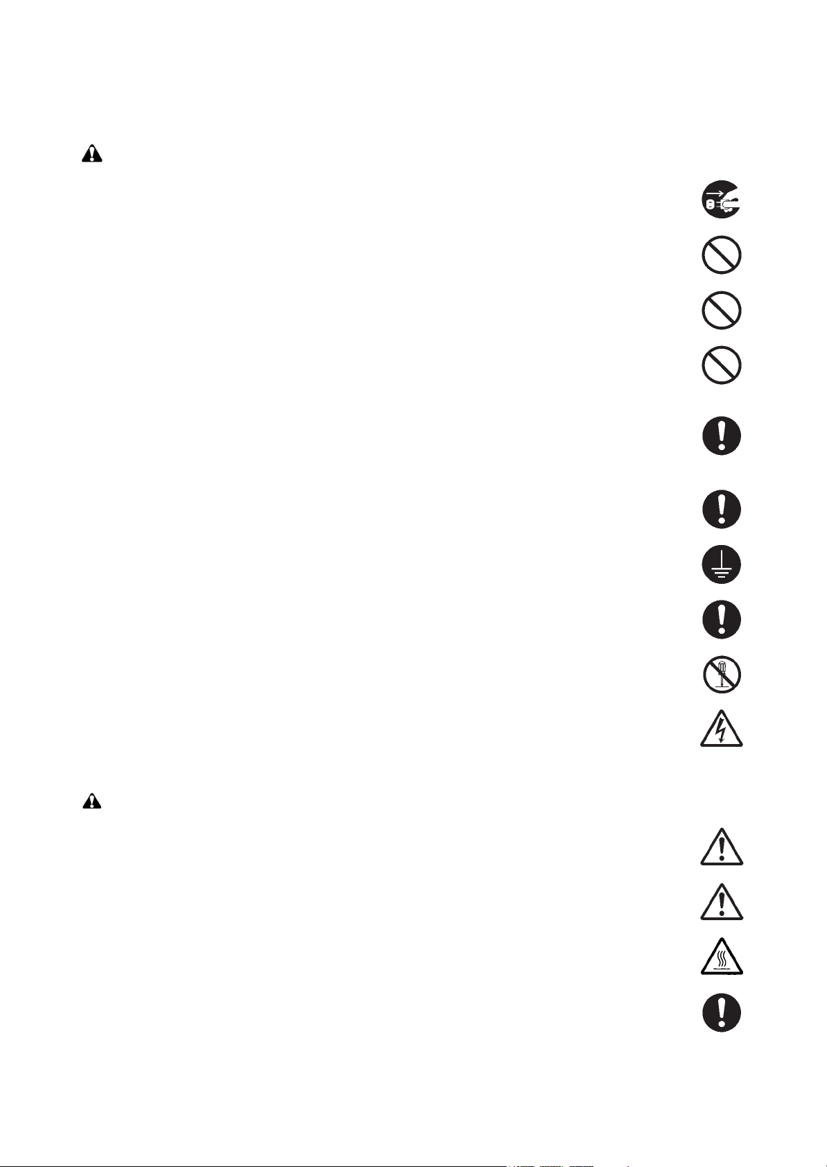
Various symbols are used to protect our service personnel and customers from physical danger and
to prevent damage to their property. These symbols are described below:
DANGER: High risk of serious bodily injury or death may result from insufficient attention to or incorrect
compliance with warning messages using this symbol.
WARNING: Serious bodily injury or death may result from insufficient attention to or incorrect compliance
with warning messages using this symbol.
CAUTION: Bodily injury or damage to property may result from insufficient attention to or incorrect com-
pliance with warning messages using this symbol.
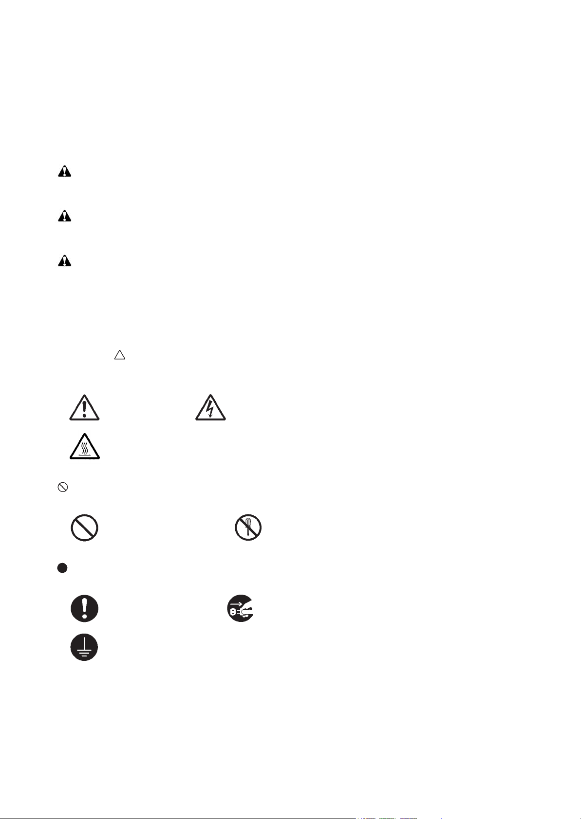
Symbols
The triangle ( ) symbol indicates a warning including danger and caution. The specific point of attention is
shown inside the symbol.
General warning. Warning of risk of electric shock.
Warning of high temperature.
indicates a prohibited action. The specific prohibition is shown inside the symbol.
General prohibited action. Disassembly prohibited.
indicates that action is required. The specific action required is shown inside the symbol.
General action required. Remove the power plug from the wall outlet.
Always ground the copier.

1. Installation Precautions
WARNING
• Do not use a power supply with a voltage other than that specified. Avoid multiple connections to
one outlet: they may cause fire or electric shock. When using an extension cable, always check that
it is adequate for the rated current......................................................................................................
• Connect the ground wire to a suitable grounding point. Not grounding the copier may cause fire or
electric shock. Connecting the earth wire to an object not approved for the purpose may cause
explosion or electric shock. Never connect the ground cable to any of the following: gas pipes, lightning rods, ground cables for telephone lines and water pipes or faucets not approved by the proper
authorities...........................................................................................................................................
CAUTION:
• Do not place the copier on an infirm or angled surface: the copier may tip over, causing injury. .........
• Do not install the copier in a humid or dusty place. This may cause fire or electric shock. .................
• Do not install the copier near a radiator, heater, other heat source or near flammable material. This
may cause fire. ...................................................................................................................................
• Allow sufficient space around the copier to allow the ventilation grills to keep the machine as cool
as possible. Insufficient ventilation may cause heat buildup and poor copying performance. ............
• Always handle the machine by the correct locations when moving it. .................................................
• Always use anti-toppling and locking devices on copiers so equipped. Failure to do this may cause
the copier to move unexpectedly or topple, leading to injury. ..............................................................
• Avoid inhaling toner or developer excessively. Protect the eyes. If toner or developer is accidentally
ingested, drink a lot of water to dilute it in the stomach and obtain medical attention immediately.
If it gets into the eyes, rinse immediately with copious amounts of water and obtain medical atten-
tion. .....................................................................................................................................................
• Advice customers that they must always follow the safety warnings and precautions in the copier’s
instruction handbook. .........................................................................................................................
2. Precautions for Maintenance
WARNING
• Always remove the power plug from the wall outlet before starting machine disassembly. ................
• Always follow the procedures for maintenance described in the service manual and other related
brochures. ..........................................................................................................................................
• Under no circumstances attempt to bypass or disable safety features including safety mechanisms
and protective circuits. ........................................................................................................................
• Always use parts having the correct specifications. ............................................................................
• Always use the thermostat or thermal fuse specified in the service manual or other related brochure
when replacing them. Using a piece of wire, for example, could lead to fire or other serious acci-
dent. ...................................................................................................................................................
• When the service manual or other serious brochure specifies a distance or gap for installation of a
part, always use the correct scale and measure carefully. ..................................................................
• Always check that the copier is correctly connected to an outlet with a ground connection. ...............
• Check that the power cable covering is free of damage. Check that the power plug is dust-free. If it
is dirty, clean it to remove the risk of fire or electric shock. .................................................................
• Never attempt to disassemble the optical unit in machines using lasers. Leaking laser light may
damage eyesight. ...............................................................................................................................
• Handle the charger sections with care. They are charged to high potentials and may cause electric
shock if handled improperly. ...............................................................................................................
CAUTION
• Wear safe clothing. If wearing loose clothing or accessories such as ties, make sure they are safely
secured so they will not be caught in rotating sections. ......................................................................
• Use utmost caution when working on a powered machine. Keep away from chains and belts. ..........
• Handle the fixing section with care to avoid burns as it can be extremely hot. ..................................
• Check that the fixing unit thermistor, heat and press rollers are clean. Dirt on them can cause
abnormally high temperatures. ...........................................................................................................

• Do not remove the ozone filter, if any, from the copier except for routine replacement. ......................
• Do not pull on the AC power cord or connector wires on high-voltage components when removing
them; always hold the plug itself. ........................................................................................................
• Do not route the power cable where it may be stood on or trapped. If necessary, protect it with a
cable cover or other appropriate item. ................................................................................................
• Treat the ends of the wire carefully when installing a new charger wire to avoid electric leaks. ..........
• Remove toner completely from electronic components. .....................................................................
• Run wire harnesses carefully so that wires will not be trapped or damaged. ......................................
• After maintenance, always check that all the parts, screws, connectors and wires that were
removed, have been refitted correctly. Special attention should be paid to any forgotten connector,
trapped wire and missing screws. .......................................................................................................
• Check that all the caution labels that should be present on the machine according to the instruction
handbook are clean and not peeling. Replace with new ones if necessary. .......................................
• Handle greases and solvents with care by following the instructions below: ......................................
· Use only a small amount of solvent at a time, being careful not to spill. Wipe spills off completely.
· Ventilate the room well while using grease or solvents.
· Allow applied solvents to evaporate completely before refitting the covers or turning the power
switch on.
· Always wash hands afterwards.
• Never dispose of toner or toner bottles in fire. Toner may cause sparks when exposed directly to
fire in a furnace, etc. ...........................................................................................................................
• Should smoke be seen coming from the copier, remove the power plug from the wall outlet immedi-
ately. ...................................................................................................................................................
3. Miscellaneous
WARNING
• Never attempt to heat the drum or expose it to any organic solvents such as alcohol, other than the
specified refiner; it may generate toxic gas. ........................................................................................
• Keep the machine away from flammable liquids, gases, and aerosols. A fire or an electric shock
might occur. ........................................................................................................................................

This page is intentionally left blank.

CONTENTS
1-1 Specifications
1-1-1 Specifications ........................................................................................................................ 1-1-1
1-1-2 Parts names .......................................................................................................................... 1-1-5
(1) Machine ............................................................................................................................ 1-1-5
(2) Operation panel ................................................................................................................ 1-1-6
1-1-3 Machine cross section ........................................................................................................... 1-1-7
(1) 20/21 ppm Model.............................................................................................................. 1-1-7
(2) 25/26 ppm Model.............................................................................................................. 1-1-8
1-2 Installation
1-2-1 Installation environment......................................................................................................... 1-2-1
1-2-2 Unpacking and installation..................................................................................................... 1-2-2
(1) Installation procedure .......................................................................................................1-2-2
1-3 Maintenance Mode
1-3-1 Maintenance mode ................................................................................................................ 1-3-1
(1) Executing a maintenance items........................................................................................ 1-3-1
1-3-2 Maintenance menu .............................................................................................................. 1-3-11
(1) Items for various settings................................................................................................ 1-3-12
(2) Service package ............................................................................................................. 1-3-13
2M2/2M3
1-4 Troubleshooting
1-4-1 Paper misfeed detection ........................................................................................................ 1-4-1
(1) Paper misfeed indication .................................................................................................. 1-4-1
(2) Paper misfeed detection condition ................................................................................... 1-4-2
1-4-2 Self-diagnostic function ......................................................................................................... 1-4-4
(1) Self-diagnostic function .................................................................................................... 1-4-4
(2) Self diagnostic codes indication ....................................................................................... 1-4-4
(3) Self diagnostic codes........................................................................................................ 1-4-6
1-4-3 Image formation problems ..................................................................................................... 1-4-8
(1) No image appears (entirely white).................................................................................... 1-4-9
(2) No image appears (entirely black).................................................................................... 1-4-9
(3) Part of image is missing. ................................................................................................ 1-4-10
(4) Gray background. ........................................................................................................... 1-4-10
(5) White streaks are printed vertically................................................................................. 1-4-11
(6) Black streaks are printed vertically. ................................................................................ 1-4-11
(7) White or black streaks are printed horizontally............................................................... 1-4-11
(8) Spots are printed.Printing incomplete or out of position ................................................. 1-4-12
(9) Printing incomplete or out of position ............................................................................. 1-4-12
(10) Paper is wrinkled. ...........................................................................................................1-4-12
(11) Offset occurs. .................................................................................................................1-4-13
(12) Fusing is loose................................................................................................................ 1-4-13
(13) Faint or blurred printing .................................................................................................. 1-4-13
(14) Dirt on the top edge or back of the paper. ...................................................................... 1-4-14
(15) Spots in the printed objects. .......................................................................................... 1-4-14
1-4-4 Electric problems ................................................................................................................. 1-4-15
1-4-5 Mechanical problems........................................................................................................... 1-4-17
1-4-6 Error Messages ................................................................................................................... 1-4-18

1-5 Assembly and disassembly
1-5-1 Precautions for assembly and disassembly........................................................................... 1-5-1
(1) Precautions....................................................................................................................... 1-5-1
(2) Drum................................................................................................................................. 1-5-1
(3) Toner ................................................................................................................................ 1-5-1
(4) How to tell a genuine Kyocera toner container................................................................. 1-5-2
1-5-2 Outer covers .......................................................................................................................... 1-5-3
(1) Detaching and refitting the top cover................................................................................ 1-5-3
(2) Detaching and refitting the Right cover ............................................................................ 1-5-4
(3) Detaching and refitting the Left cover............................................................................... 1-5-5
1-5-3 Fuser section ......................................................................................................................... 1-5-6
(1) Detaching and refitting the fuser unit................................................................................ 1-5-6
1-5-4 PWBs..................................................................................................................................... 1-5-7
(1) Detaching and refitting the main PWB,high voltage PWB and power source PWB .........1-5-7
(2) Detaching and refitting the operation panel PWB........................................................... 1-5-11
1-5-5 Others .................................................................................................................................. 1-5-12
(1) Detaching and refitting the laser scanner unit ................................................................ 1-5-12
(2) Detaching and refitting the Main motor unit.................................................................... 1-5-14
(3) Direction of installing the principal fan motor.................................................................. 1-5-20
2M2/2M3-1
2-1 Mechanical Construction
2-1-1 Paper feed/conveying section ............................................................................................... 2-1-1
(1) Cassette paper feed /paper conveying section ................................................................ 2-1-1
(2) Manual feed section (25/26 ppm model only)................................................................... 2-1-2
2-1-2 Drum section ......................................................................................................................... 2-1-4
2-1-3 Developer section .................................................................................................................. 2-1-5
2-1-4 Optical section ....................................................................................................................... 2-1-6
(1) Laser scanner section ...................................................................................................... 2-1-6
2-1-5 Transfer/Separation section ..................................................................................................2-1-9
2-1-6 Fuser section ....................................................................................................................... 2-1-10
2-1-7 Duplex conveying/Eject section ........................................................................................... 2-1-12
2-2 Electrical Parts Layout
2-2-1 Electrical parts layout ............................................................................................................ 2-2-1
(1) PWBs................................................................................................................................ 2-2-1
(2) Switches and sensors....................................................................................................... 2-2-3
(3) Others............................................................................................................................... 2-2-4
2-3 Operation of the PWBs
2-3-1 Main PWB.............................................................................................................................. 2-3-1
2-3-2 Relay PWB PWB ...................................................................................................................2-3-4
2-3-3 Power source PWB ............................................................................................................... 2-3-6
2-3-4 Operation panel PWB............................................................................................................ 2-3-8
2-4 Appendixes
2-4-1 Maintenance kits.................................................................................................................... 2-4-1
(1) Maintenance kits............................................................................................................... 2-4-1
2-4-2 Procedure for replacing Maintenance kit ............................................................................... 2-4-2
(1) Checking the components included and
preparing the paper-feed replacement unit for installation ............................................... 2-4-2
(2) Preparation ....................................................................................................................... 2-4-4
(3) Detaching the Drum unit................................................................................................... 2-4-6

2M2/2M3
(4) Detaching the developer unit............................................................................................ 2-4-7
(5) Detaching the toner disposal box ..................................................................................... 2-4-7
(6) Detaching and refitting the paper feed pulley and lower paper feed guide ...................... 2-4-8
(7) Refitting the toner disposal box ...................................................................................... 2-4-12
(8) Refitting the developer unit............................................................................................. 2-4-12
(9) Refitting the drum unit .................................................................................................... 2-4-13
(10) Detaching and refitting the transfer roller ....................................................................... 2-4-14
(11) Notice after replacing maintenance kit ........................................................................... 2-4-15
(12) Procedure for only replacing Drum unit .......................................................................... 2-4-16
(13) Procedure for only replacing Developer unit .................................................................. 2-4-16
2-4-3 Cleaning the Printer ............................................................................................................. 2-4-17
2-4-4 Appendixes .......................................................................................................................... 2-4-18
(1) Repetitive defects gauge ................................................................................................ 2-4-18
(2) Wiring diagram ............................................................................................................... 2-4-19

2M2/2M3
This page is intentionally left blank.
1-1 Specifications
1-1-1 Specifications
Machine
2M2/2M3-1
Item
20/21 ppm 25/26 ppm
Type Desktop
Printing method Electrophotography by semiconductor laser
2
Paper weight
Cassette 60 to 220 g/m
Manual feed
-
tray*
Paper type
Cassette/
Manual feed
tray*
Plain, Preprinted, Labels, Bond, Recycled, Vellum, Rough, Letterhead,
Color, Prepunched, Envelope, Cardstock, Thick paper, High Quality, Custom 1 to 8
A4, JIS/ISO B5, A5, Folio, Legal, Letter, Oficio II (215.9 × 330.2 mm, 8-1/2
× 13 inches), Mexican Oficio (216 × 340 mm), Statement, Executive, A6,
Cassette
Envelope Monarch, Envelope #10, Envelope #9, Envelope #6-3/4, Envelope C5, Envelope DL, 16K, Custom (70 × 148 to 216 × 356 mm (2-3/4 × 513/16 to 8-1/2 × 14 inches)
- A4, JIS/ISO B5, A5, Folio, Legal,
Paper size
Manual feed
tray*
Specifications
60 to 220 g/m
Letter, Oficio II (215.9 × 330.2 mm,
8-1/2 × 13 inches), Mexican Oficio
(216 × 340 mm), Statement, Executive, A6, Envelope Monarch, Envelope #10, Envelope #9, Envelope
#6-3/4, Envelope C5, Envelope DL,
16K, Custom (70 × 148 to 216 × 356
mm (2-3/4 × 5-13/16 to 8-1/2 × 14
inches)
2
Paper weight
setting
Printing
speed
(images/min)
Light 63 g/m² or less
Normal 1 64 to 69 g/m²
Normal 2(3) 70 to 105 g/m²
Heavy 1 106 to 135 g/m²
Heavy 2(3) 136 to 220 g/m²
Light: 20
A4
Normal 1: 20
Normal 2(3): 20
Light: 15
A4(Quiet
Mode)
Normal 1: 15
Normal 2(3): 15
Heavy 1: 14
Heavy 2(3): 13
Light: 21
Letter
Normal 1: 21
Normal 2(3): 21
Light: 25
Normal 1: 25
Normal 2(3): 25
Light: 18
Normal 1: 18
Normal 2(3): 18
Heavy 1: 17
Heavy 2(3): 16
Light: 26
Normal 1: 26
Normal 2(3): 26
1-1-1

2M2/2M3-1
Printing
speed
(images/min)
Item
Letter(Quiet
Mode)
A5/B5/A6
(Quiet Mode)
A5/B5/
A6(from 11th
image)
(Quiet Mode)
Legal
20/21 ppm 25/26 ppm
Light: 16
Normal 1: 16
Normal 2(3): 16
Heavy 1: 14
Heavy 2(3): 13
Light: 12
Normal 1: 12
Normal 2(3): 12
Heavy 1: 10
Heavy 2(3): 9
Light: 10
Normal 1: 10
Normal 2(3): 10
Heavy 1: 8
Heavy 2(3): 8
Light: 13
Normal 1: 13
Normal 2(3): 13
Specifications
Light: 19
Normal 1: 19
Normal 2(3): 19
Heavy 1: 17
Heavy 2(3): 16
Light: 15
Normal 1: 15
Normal 2(3): 15
Heavy 1: 13
Heavy 2(3): 12
Light: 12
Normal 1: 12
Normal 2(3): 12
Heavy 1: 11
Heavy 2(3): 10
Light: 20
Normal 1: 20
Normal 2(3): 20
Duplex
Printing
speed
(images/min)
Legal(Quiet
Mode)
A4
A4(Quiet
Mode)
Letter
Letter(Quiet
Mode)
Light: 12
Normal 1: 12
Normal 2(3): 12
Heavy 1: 11
Heavy 2(3): 10
-Light: 15
-Light: 11
-Light: 15
-Light: 11
Light: 15
Normal 1: 15
Normal 2(3): 15
Heavy 1: 13
Heavy 2(3): 11
Normal 1: 15
Normal 2(3): 15
Normal 1: 11
Normal 2(3): 11
Heavy 1: 11
Heavy 2(3): 11
Normal 1: 15
Normal 2(3): 15
Normal 1: 11
Normal 2(3): 11
Heavy 1: 11
Heavy 2(3): 11
Legal
-Light: 13
Normal 1: 13
Normal 2(3): 13
1-1-2

2M2/2M3-1
Item
Duplex
Printing
speed
(images/min)
Legal(Quiet
Mode)
First print time
(A4, feed from cassette)
Warm-up
Power on 14 s or less
time
(22 °C/71.6
Sleep
°F, 60% RH)
Cassette 250 sheets (80 g/m
Paper
capacity
Manual feed
tray*
Standard
Output tray
capacity
paper
Special
paper
Specifications
20/21 ppm 25/26 ppm
-Light: 10
Normal 1: 10
Normal 2(3): 10
Heavy 1: 9
Heavy 2(3): 9
8.5 s or less
7.5 s or less
16 s or less
12 s or less
-
150 sheets (80 g/m
-
2
)
2
)
14 s or less
1 sheet
1 sheet
Continuous printing 1 to 999 sheets
Photoconductor OPC drum (drum diameter 24 mm)
Image write system Semiconductor laser (1 beam)
Charging system Charger roller
Developing system
Mono component dry developing method
Toner replenishing: Automatic from the toner container
Transfer system Transfer roller
Separation system Small diameter separation, discharger brush
Cleaning system Counter blade
Charge erasing system Exposure by eraser lamp (LED)
Fusing system
Heat roller system
Abnormally high temperature protection devices: thermostat
Controller ARM926EJ 390MHz
Supported OS Microsoft Windows XP/Vista/7, Windows Server 2003/2008, Mac OS X 10.x
USB Interface connector: 1 (USB HiSpeed)
Interface
USB Interface connector: 1 (USB HiSpeed)
Network interface: 1 (10 BASE-T/
100 BASE-TX [TCP/IP, WSD]) <This
unit does not support the NetBEUI.>
Memory 32 MB (Maxmum 32 MB)
Resolution 600 dpi/ Fast 1200 dpi
1-1-3

2M2/2M3-1
Item
Temperature 10 to 32.5 °C/50 to 90.5 °F
Humidity 15 to 80% RH
Operating
environment
Dimensions
(W × D × H)
Space required (W × D)
Weight 6.3 kg/13.86 lb
Power source
*:The Manual Feed tray is only provided on the 25/26 ppm model.
NOTE: These specifications are subject to change without notice.
Altitude
Brightness 1,500 lux maximum
machine
only
3,500 m/11,482.8 ft maximum
High altitude mode is available for regular operation at less than 1500m or
1500 – 3500m.
358 × 262 × 241 mm
14 1/8 × 10 5/16 × 9 1/2”
358 × 645 mm
(using paper feed tray)
14 1/8 × 25 3/8”
120 V Specification Model:120 V (60 Hz, 5.4 A)
230 V Specification Model: 220 to 240 V (50 Hz/60 Hz, 2.8 A)
20/21 ppm 25/26 ppm
Specifications
358 × 276 × 241 mm
14 1/8 × 10 7/8 × 9 1/2”
358 × 630 mm
(using paper feed tray)
14 1/8 × 24 13/16”
6.7 kg/14.74 lb
1-1-4
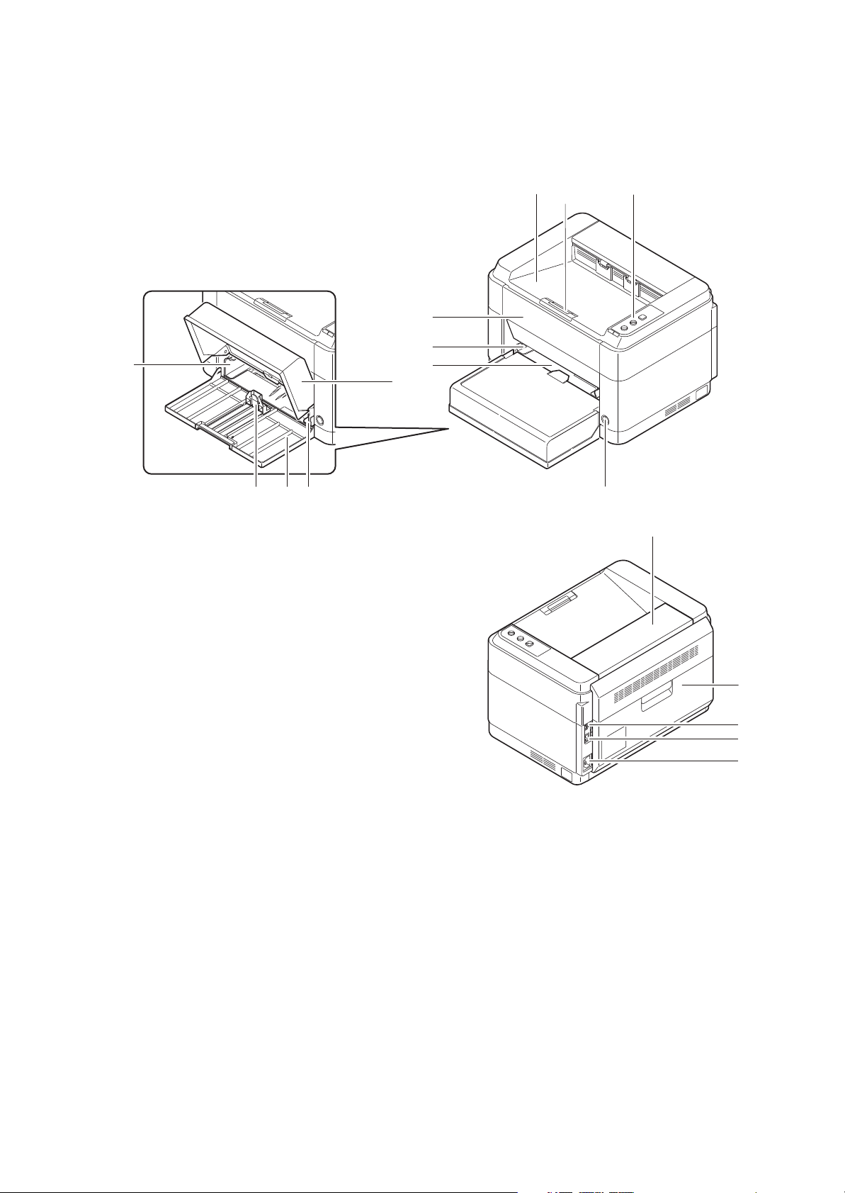
1-1-2 Parts names
1. Top tray
2. Paper stopper
3. Operation panel
4. Power switch
5. Front cover
6. Manual feed paper width guides*
7. Manual feed tray*
8. Cassette cover
9. Cassette
10. Paper width guides
11. Paper length guide
12. Fuser top cover
13. Rear cover
14. USB interface connector
15. Network interface connector*
16. Power code connector
(1) Machine
10
2M2/2M3
1
23
5
6
7
8
9 1011
4
12
13
14
15
16
Figure 1-1-1
*: 25/26 ppm model only.
1-1-5
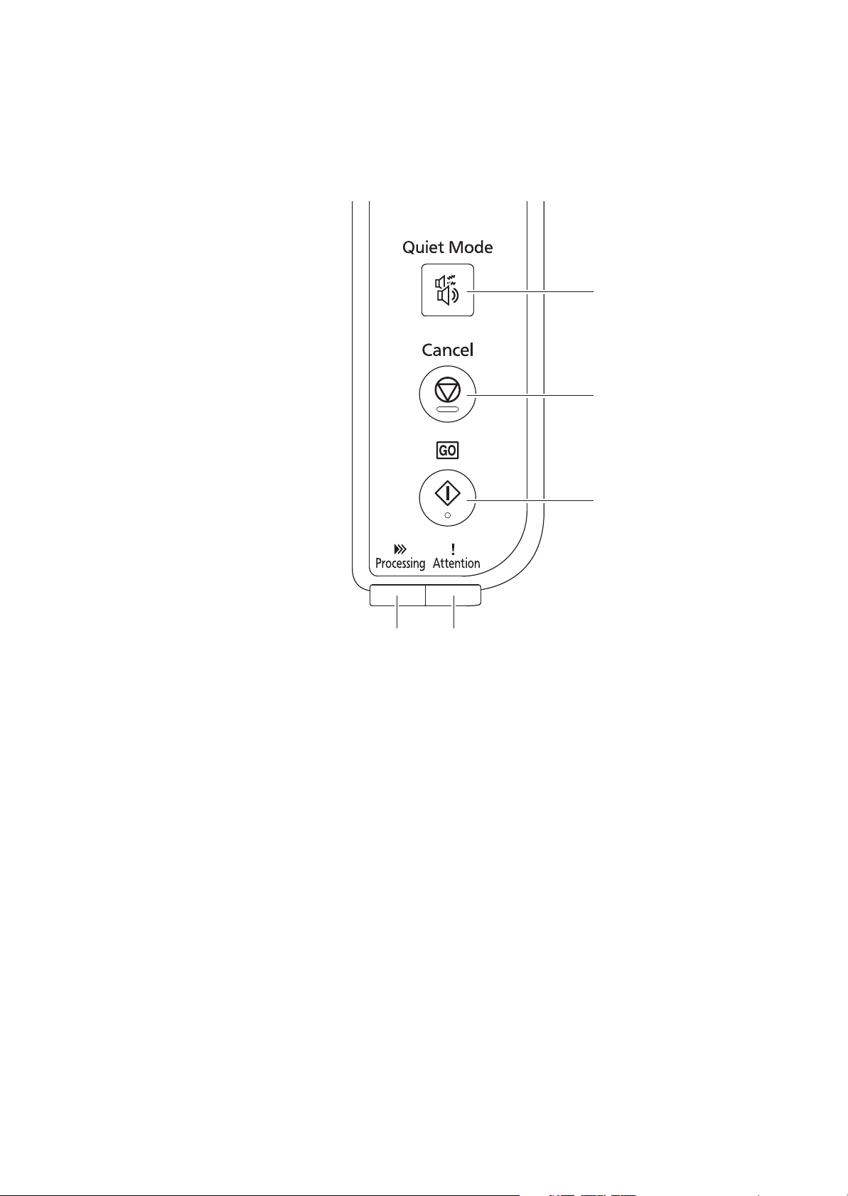
(2) Operation panel
1. Processing indicator
2. Attention indicator
3. Go key
4. Cancel key
5. Quiet Mode key
2M2/2M3
5
4
21
Figure 1-1-2
3
1-1-6
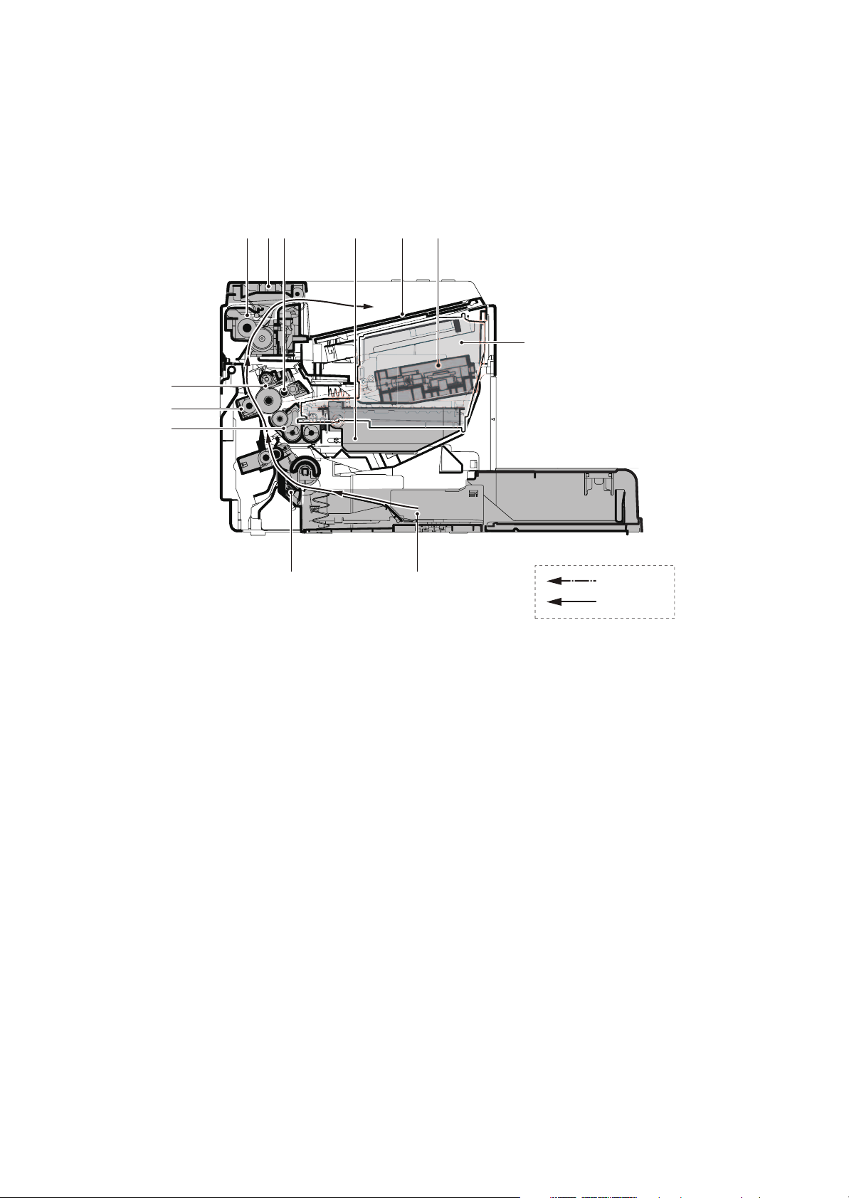
1-1-3 Machine cross section
1. Cassette
2. Paper feed/conveying section
3. Toner container
4. Developing unit
5. Waste toner box
6. Drum charge roller
7. Drum unit
8. Transfer/separation section
9. Laser scanner unit
10. Fuser section
11. Exit section
12. Top tray
(1) 20/21 ppm Model
2M2/2M3
6
5
12
91110
3
7
8
4
2
1
Light path
Paper path
Figure 1-1-3
1-1-7
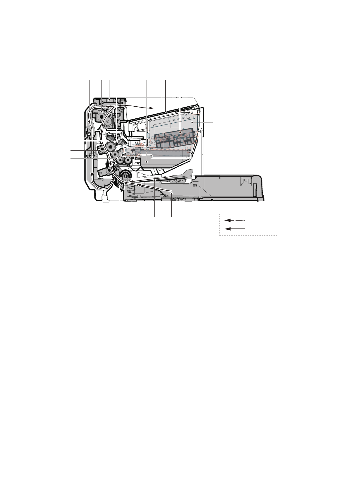
(2) 25/26 ppm Model
1. Cassette
2. Paper feed/conveying section
3. Manual feed tray
4. Toner container
5. Developing unit
6. Waste toner box
7. Drum charge roller
8. Drum unit
9. Transfer/separation section
10. Laser scanner unit
11. Fuser section
12. Feedshift/exit section
13. Duplex conveying section
14. Top tray
2M2/2M3
13
7
6
14
101211
4
8
9
5
2
1
3
Light path
Paper path
Figure 1-1-4
1-1-8
1-2 Installation
1-2-1 Installation environment
1. Temperature: 10 to 32.5°C/50 to 90.5°F
2. Humidity: 15 to 80% RH
3. Power supply: 120 V AC, 5.4 A
220 - 240 V AC, 2.8 A
4. Power source frequency: 50 Hz ± 2%/60 Hz ± 2%
5. Installation location
Avoid direct sunlight or bright lighting. Ensure that the photoconductor will not be exposed to direct sunlight or other strong light when removing paper jams.
Avoid locations subject to high temperature and high humidity or low temperature and low humidity; an
abrupt change in the environmental temperature; and cool or hot, direct air.
Avoid places subject to dust and vibrations.
Choose a surface capable of supporting the weight of the machine.
Place the machine on a level surface (maximum allowance inclination: 1°).
Avoid air-borne substances that may adversely affect the machine or degrade the photoconductor, such
as mercury, acidic of alkaline vapors, inorganic gasses, NOx, SOx gases and chlorine-based organic solvents.
Select a well-ventilated location.
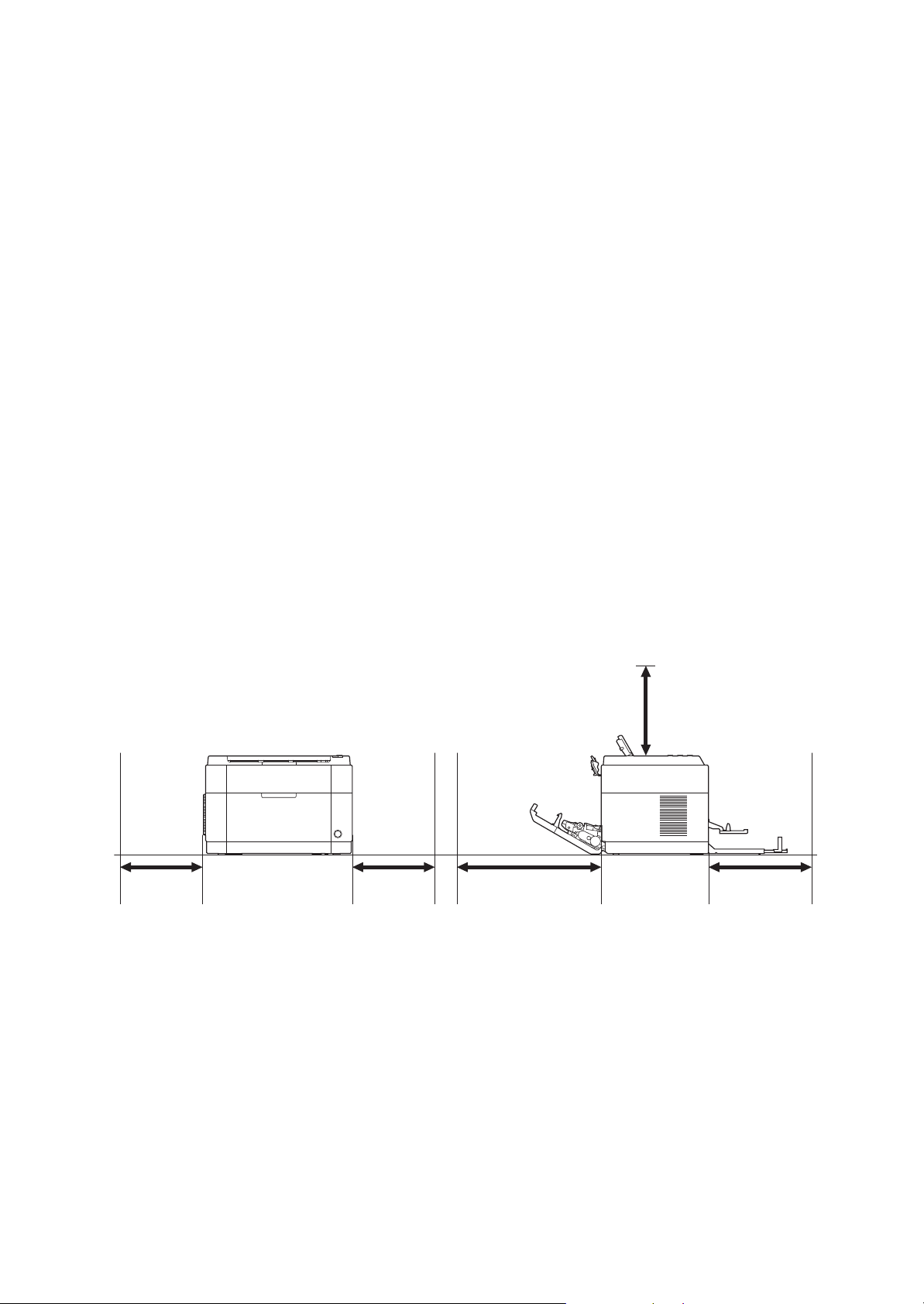
6. Allow sufficient access for proper operation and maintenance of the machine.
Machine front : 25 cm/ 10"
Machine rear : 35 cm/ 14"
Machine right : 20 cm/ 8"
Machine left : 20 cm/ 8"
Machine top : 40 cm/ 15 3/4”
2M2/2M3
200 mm
(8")
200 mm
(8")
Figure 1-2-1
350 mm
(14")
400 mm
(15-3/4")
250 mm
(10")
1-2-1
1-2-2 Unpacking and installation
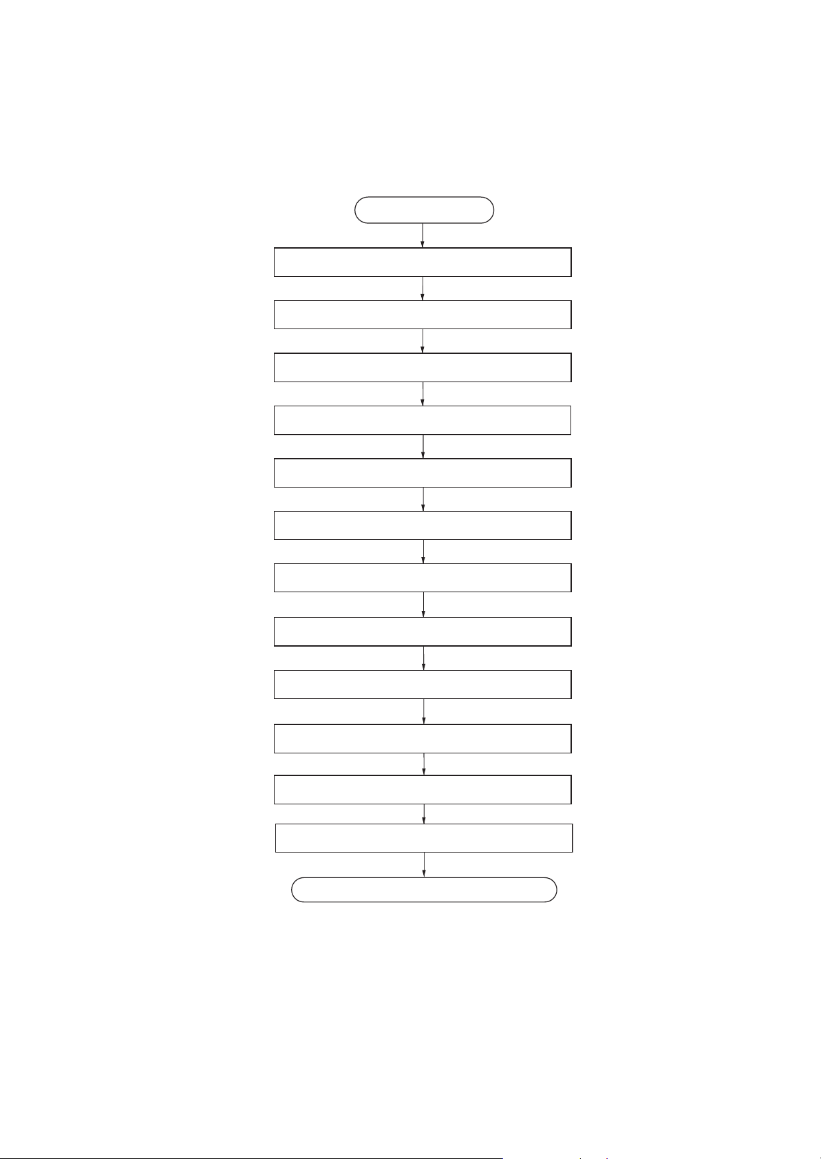
(1) Installation procedure
Start
Unpacking
Taking out the machine
Removing the tapes
Installing the cassette cover
2M2/2M3
Loading paper (cassette)
Installing the toner container
Connect the USB cable
Connect the Network cable (25/26 ppm model)
Connect the power cord
Installing the toner
Make test printing
Installing the printer driver
Completion of the machine installation.
Figure 1-2-2
1-2-2
2M2/2M3-1
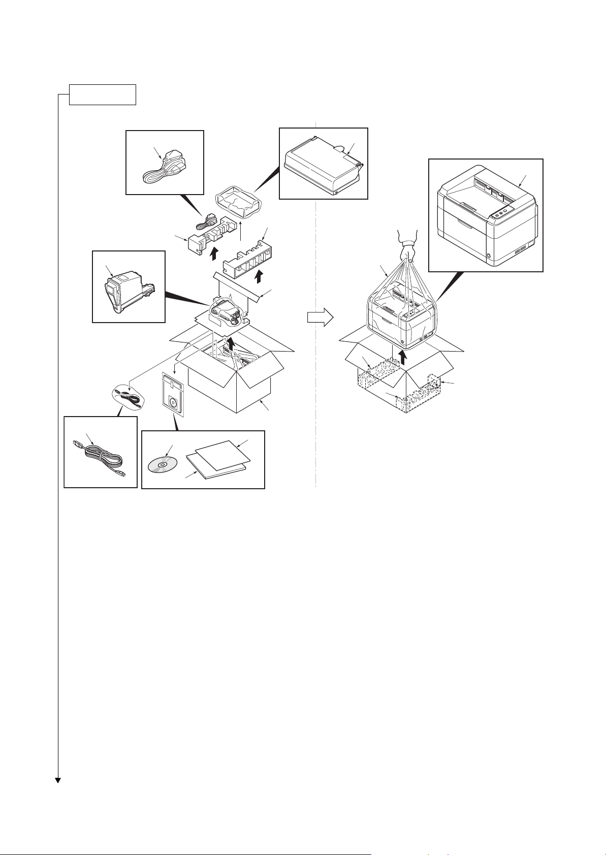
Unpacking
1. Machine
2. Outer case
3. Bottom left pad
4. Bottom right pad
5. Machine cover
6. Top left pad
7. Top right pad
8. Top spacer
9. Cassette cover
10. Power cord
11. Toner container
12. CDROM
13. Quick installation guide
14. Leaflet etc.
15. USB cable*1
16. Bottom spacer*2
*1:Chaina model only
*2:20/21 ppm Model only
15
10
7
6
11
8
2
12
14
9
1
5
3
16
4
13
*: Place the machine on a level surface.
Figure 1-2-3
1-2-3
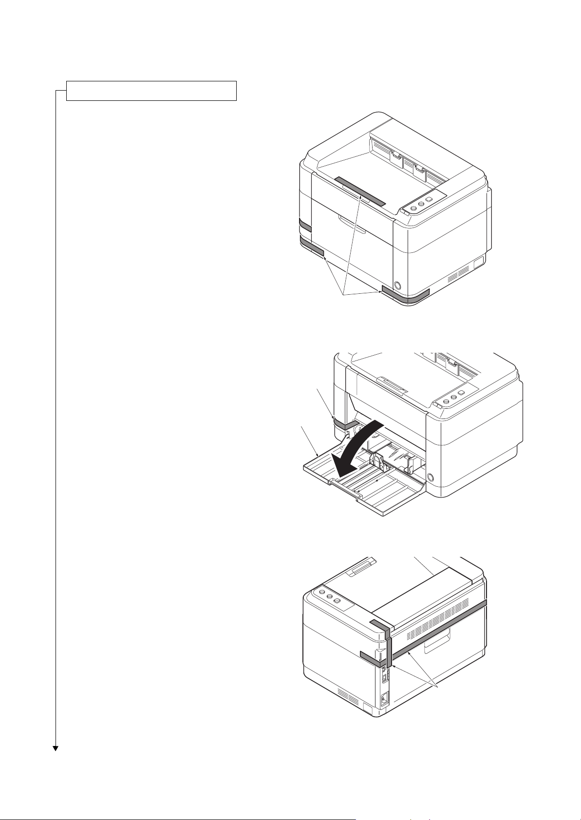
20/21 ppm Model
Removing the tapes
Cassette
Ta pe
1. Remove three tapes.
2M2/2M3-1
Tapes
Figure 1-2-4
2. Open the cassette.
3. Remove tape.
4. Open the front cover.
Figure 1-2-5
Ta pe s
Figure 1-2-6
1-2-4
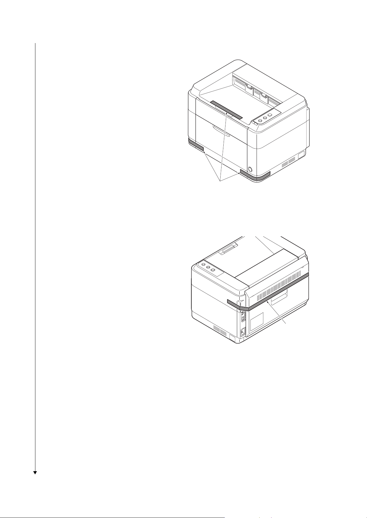
25/26 ppm Model
Ta pe
1. Remove three tapes.
2M2/2M3-1
Ta pe s
Figure 1-2-7
2. Remove tape.
Figure 1-2-8
1-2-5
2M2/2M3
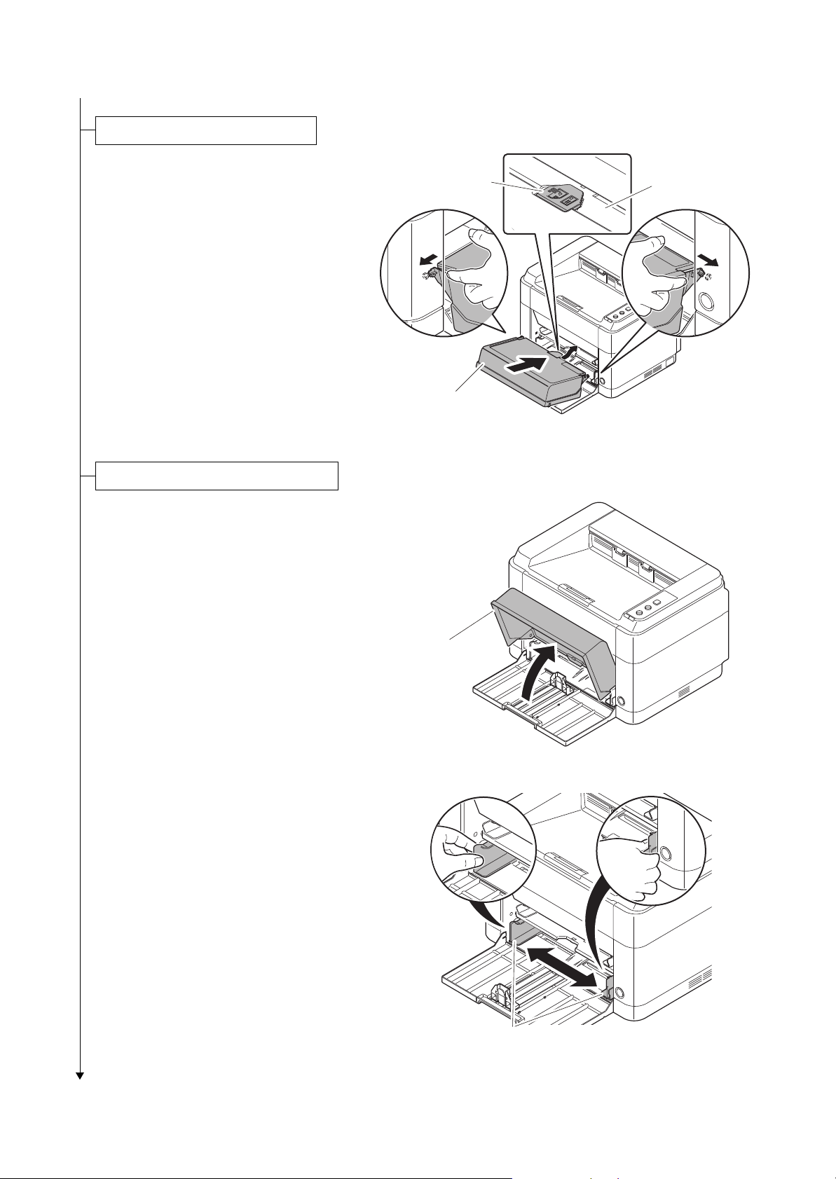
Installing the cassette cover
Loading paper (cassette)
1. Attach the cassette cover.
Attach the cassette cover so that its
right and left-side pins and the boss on
the machine frame mate with each
other.
*: If performing installation in a 25 ppm
model, install the cassette cover so that
its guide at the top is positioned above
the MF base.
1. Open the cassette cover.
Guide
Cassette cover
MF base
Figure 1-2-9
2. Adjust the position of the width guides
located on the left and right sides of the
cassette.
*:
Paper sizes are marked on the cassette.
Cassette cover
Figure 1-2-10
Paper width guides
Figure 1-2-11
1-2-6
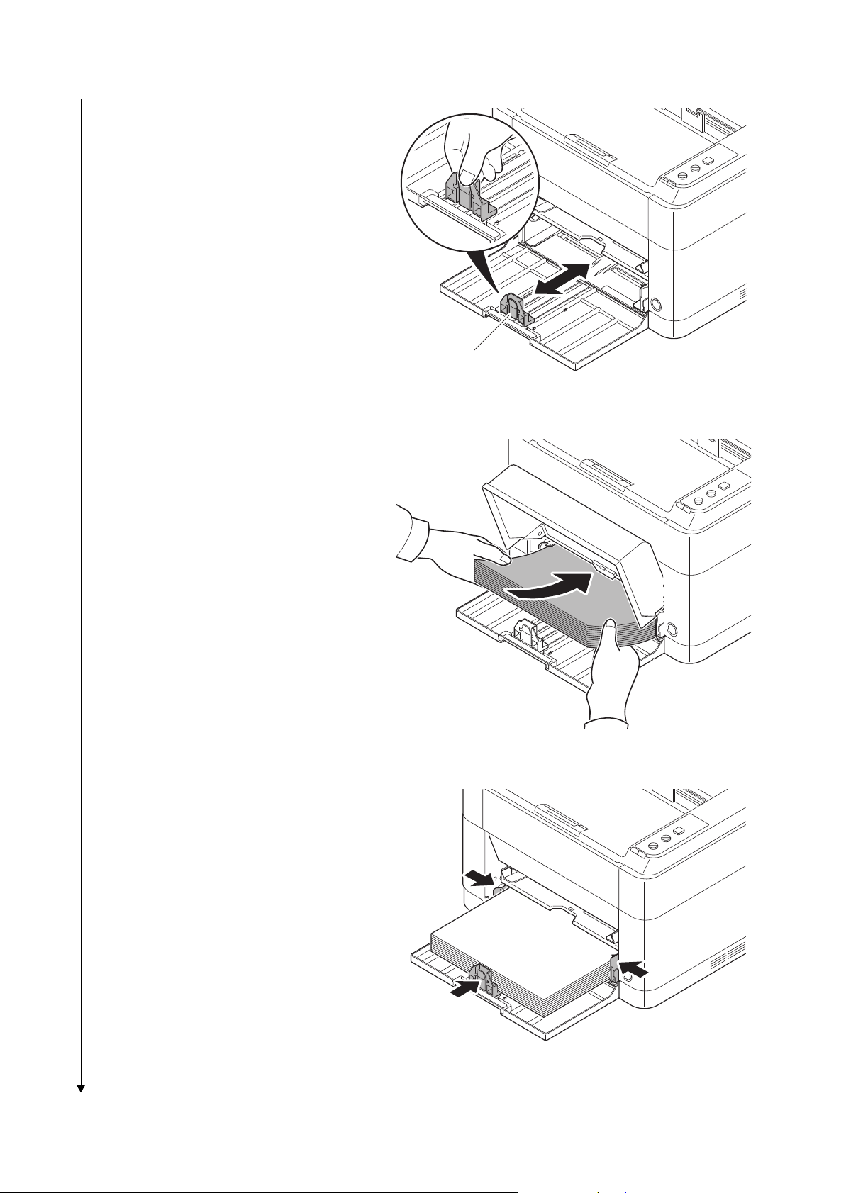
3. Adjust the paper length guide to the paper
size required.
4. Load the paper all the way in the cassette until the paper touches the far
inner side.
*: Ensure the side to be printed is facing up
and the paper is not folded, curled, or
damaged.
2M2/2M3
Paper length guide
Figure 1-2-12
*: Adjust so that there is no gap between
the paper length guide and the paper.
Figure 1-2-13
Figure 1-2-14
1-2-7

*: Load an amount of paper that fits under
the tabs on the width guides.
*: Ensure that the loaded paper does not
exceed the level indicated.
2M2/2M3
Ta bs
Exceed the level indicated
Figure 1-2-15
5. Close the cassette cover.
Figure 1-2-16
1-2-8
Loading...