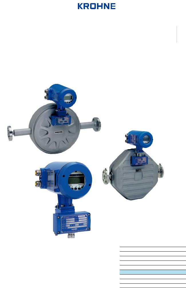
KROHNE CORIMASSE User Manual

|
© KROHNE 07/2000 |
D 31 IF10 02 D |
|
|
|
|
|
|
|
|
|
|
|
|
|
|
|
||
|
|
|
|
|
|
|
|
||
|
|
|
|
|
|
|
|
|
|
|
|
|
|
|
|
|
|
|
|
|
GR |
|
|
|
|
|
|
|
|
Addition to the installation and operating instructions
CORIMASS E + P Class
MFM 3081 K/F
MFM 2081 K/F
Ex-Version
Variable area flowmeters Vortex flowmeters
Flow controllers Electromagnetic flowmeters Ultrasonic flowmeters
Mass flowmeters
Level measuring instruments Communications engineering Engineering systems & solutions

These instructions should be used in conjunction with the Standard Installation and Operating Instructions for the MFM 2081/3081 K/F. If you require a copy, please contact your nearest KROHNE Office or representative.
Product liability and warranty
The CORIMASS mass flowmeter MFM 2081/3081 K/F is designed for the direct measurement of mass flow rate, product density and product temperature, and also indirectly enables measurement of parameters such as total mass, concentration of dissolved substances and the volume flow.
For use in hazardous areas, special codes and regulations are applicable which are specified in the special ”Ex installation and operating instructions” (supplied only with hazardous-duty equipment).
Responsibility as to suitability and intended use of our instruments rests solely with the purchaser.
Improper installation and operation of the flowmeters may lead to loss of warranty.
In addition, the ”general conditions of sale” forming the basis of the purchase agreement are applicable.
If you need to return CORIMASS flowmeters to KROHNE, please complete the form on the last page of the Installation and Operating manual and return it with the meter to be repaired. KROHNE regrets that it cannot repair or check your flowmeter unless accompanied by this completed form.
Content |
|
|
1 |
Description.................................................................................................... |
3 |
1.1 |
Description of the Transducer ............................................................................ |
4 |
1.2 |
Description of the Converter .............................................................................. |
4 |
1.3 |
Installation of MFM 2081 / MFM 3081 EEx........................................................ |
5 |
2 |
Electrical installation................................................................................... |
6 |
2.1 |
Location and connecting cables ........................................................................ |
6 |
2.2 |
Electrical Connection on converter without intrinsically safe outputs..................... |
6 |
2.3 |
Electrical connection on converter with intrinsically safe outputs.......................... |
9 |
2 |
Additional Instruction for Ex version MFM 2081 / 3081 |

1 Description
The mass flowmeter MFM 2081/3081 K EEx and MFM 2081/3081 F EEx consists of two main components:
The Signal Converter, which calculates and displays the measured values and the transducer which supplies the converter with the analog signals.
A Cable Seal, which is screwed into the converter housing, leads the electric signals from the transducer to the converter. The signal cable between the transducer and converter is intrinsically safe.
In the separate version MFM 20381/3081 F EEx the transducer MFS 2000/3000 EEx and the converter MFC 081 F EEx are connected to each other via a shielded multi-conductor cable. The maximum cable length is 50 m.
The converter housing of the compact version MFM 2081/3081 K EEx is permanently screwed onto the transducer and must not be removed at any time.
Cenelec Approvals
PTB approves the conformity of the mass flow meter according to the harmonized European Standards:
EN50018 |
"d" - Pressure tight housing |
|
|
for the electronics housing and the terminal compartment |
|
EN50019 |
"e" - Increased safety |
|
for the standard termination compartment |
||
|
||
EN50020 |
"i" - Intrinsically Safe |
|
|
||
|
"b" for the Zener barriers and all electrical circuits inside the transducer |
|
|
"a" for the converter outputs |
The following approvals are valid:
Compact P and E meters, including intrinsically safe
EEx de [ib] IIC T6...T3 |
MFM 2081 K |
PTB Ex 96.D.2037 X |
EEx d [ib] IIC T6-T3 |
MFM 3081 K |
|
EEx de [ia/ib] IIC T6-T3 |
MFM 2081 Ki |
|
EEx d [ia/ib] IIC T6-T3 |
MFM 3081 Ki |
|
Converter, remote mounted version, including intrinsically safe |
||
|
|
|
EEx de [ib] IIC T6-T3 |
MFC 081 F |
PTB Ex 98.D.2037 X |
EEx d [ib] IIC T6-T3 |
MFC 081 Fi |
|
EEx de [ia/ib] IIC T6-T3 |
|
|
EEx d [ia/ib] IIC T6-T3 |
|
|
P meter, remote mounted version |
|
|
|
|
|
EEx ib IIC T6-T3 |
MFS 2000 F |
PTB Ex 98.D.2038 X |
E meter, remote mounted version |
|
|
|
|
|
EEx ib IIC T6-T3 |
MFS 3000 F |
PTB Ex 98.D.2039 X |
Additional Instruction for Ex version MFM 2081 / 3081 |
3 |
 Loading...