


KitchenAid KOCE507ESS07, KOCE507ESS00, KOCE507EWH08, KOCE507EWH07, KOCE507EWH00 Installation Guide
...INSTALLATION INSTRUCTIONS
27" (68.6 CM) AND 30" (76.2 CM) ELECTRIC BUILT-IN MICROWAVE/OVEN COMBINATION
INSTRUCTIONS D’INSTALLATION
ENSEMBLE FOUR À MICRO-ONDES ET FOUR CONVENTIONNEL ÉLECTRIQUES ET ENCASTRÉS DE 27" (68,6 CM) ET 30" (76,2 CM)
Table of Contents/Table des matières
BUILT-IN MICROWAVE/OVEN COMBINATION SAFETY............. |
2 |
INSTALLATION REQUIREMENTS................................................. |
2 |
Tools and Parts............................................................................. |
2 |
Built-In Microwave/Oven Combination |
|
Location Requirements................................................................. |
2 |
Electrical Requirements................................................................ |
3 |
INSTALLATION INSTRUCTIONS................................................... |
4 |
Prepare Built-In Microwave/Oven Combination.......................... |
4 |
Remove Oven Door(s)................................................................... |
4 |
Replace Oven Door(s)................................................................... |
5 |
Make Electrical Connection.......................................................... |
6 |
Install Oven................................................................................... |
7 |
Install Warming Drawer Deflector Kit (Only for Ovens |
|
Installed Above Warming Drawers).............................................. |
7 |
Complete Installation.................................................................... |
8 |
SÉCURITÉ DU FOUR À MICRO-ONDES ET DU FOUR |
|
CONVENTIONNEL COMBINÉS ET ENCASTRÉS........................ |
9 |
EXIGENCES D’INSTALLATION...................................................... |
9 |
Outils et pièces............................................................................. |
9 |
Exigences d’emplacement pour ensemble four/four à |
|
micro-ondes encastré................................................................. |
10 |
Spécifications électriques........................................................... |
11 |
INSTRUCTIONS D’INSTALLATION............................................. |
12 |
Préparation de l’ensemble four à micro-ondes et four |
|
conventionnel encastrés............................................................. |
12 |
Dépose de la/des porte(s) du four.............................................. |
12 |
Réinstallation de la/des porte(s) du four..................................... |
12 |
Raccordement électrique........................................................... |
13 |
Installation du four...................................................................... |
14 |
Installation de l’ensemble de déflecteur pour tiroir-réchaud |
|
(uniquement pour les fours installés au-dessus d’un tiroir- |
|
réchaud)...................................................................................... |
15 |
Achever l’installation................................................................... |
16 |
IMPORTANT:
Save for local electrical inspector's use.
IMPORTANT :
À conserver pour consultation par l'inspecteur local des installations électriques.
W10725683C
BUILT-IN MICROWAVE/OVEN COMBINATION SAFETY
Your safety and the safety of others are very important.
many important safety messages in this manual and on your appliance. Always read and obey all safety
safety alert symbol.
alerts you to potential hazards that can kill or hurt you and others.
messages will follow the safety alert symbol and either the word “DANGER” or “WARNING.”
mean:
 DANGER
  WARNING
You can be killed or seriously injured if you don't immediately follow instructions.
You can be killed or seriously injured if you don't follow instructions.
All safety messages will tell you what the potential hazard is, tell you how to reduce the chance of injury, and tell you what can happen if the instructions are not followed.
INSTALLATION REQUIREMENTS
Tools and Parts
Gather the required tools and parts before starting installation. Read and follow the instructions provided with any tools listed here.
Tools Needed
■■ Phillips screwdriver ■■ Measuring tape
■■ Drill (for wall cabinet installations)
■■ 1" (2.5 cm) drill bit (for wall cabinet installations) ■■ Level
■■ Flat-blade screwdriver
Parts Needed
■■ UL listed or CSA approved conduit connector ■■ UL listed wire connectors
■■ Warming Drawer Deflector Kit (for ovens installed above a warming drawer)
Order Part Number W10489566B for white 27" (68.6 cm) kit Order Part Number W10489564B for black 27" (68.6 cm) kit
Order Part Number W10489568A for stainless steel 27" (68.6 cm) kit
Order Part Number W10489567B for white 30" (76.2 cm) kit Order Part Number W10489565B for black 30" (76.2 cm) kit
Order Part Number W10489569A for stainless steel 30" (76.2 cm) kit
Order Part Number W10727416A for stainless steel/black 30" (76.2 cm) kit
To order, see the “Assistance or Service” section of the Use and Care Guide.
■■ Flush Installation Kit (for Combo installed at flush installation) Order Part Number W10752694A for white 27" (68.6 cm) kit Order Part Number W10752695A for black 27" (68.6 cm) kit
Order Part Number W10752696A for stainless steel 27" (68.6 cm) kit
Order Part Number W10752687A for white 30" (76.2 cm) kit Order Part Number W10752688A for black 30" (76.2 cm) kit
Order Part Number W10752693A for stainless steel 30" (76.2 cm) kit
Order Part Number W10752691A for black/stainless steel 30" (76.2 cm) kit
To order, see the “Assistance or Service” section of the Use and Care Guide.
Parts Supplied
■■ #8-14 x 1" (2.5 cm) screws (4) ■■ Bottom vent
■■ #8-18 x 3/8" (9.5 mm) screws - bottom vent (2)
Check local codes. Check existing electrical supply. See the “Electrical Requirements” section.
It is recommended that all electrical connections be made by a licensed, qualified electrical installer.
Built-In Microwave/Oven Combination
Location Requirements
IMPORTANT: Observe all governing codes and ordinances.
■■ Cabinet opening dimensions that are shown must be used. Given dimensions provide minimum clearance with oven.
■■ Recessed installation area must provide complete enclosure around the recessed portion of the oven.
■■ Grounded electrical supply is required. See “Electrical Requirements” section.
2
■■ Electrical supply junction box should be located 3" (7.6 cm) maximum below the support surface when the oven is installed in a wall cabinet. A 1" (2.5 cm) minimum diameter hole should have been drilled in the left rear corner of the support surface to pass the appliance cable through to the junction box.
■■ Oven support surface must be solid, level and flush with bottom of cabinet cutout. Floor must be able to support a total weight (microwave and built-in oven) of 208 lbs (95 kg) for 27" (68.6 cm) models or 249 lbs (113 kg) for 30" (76.2 cm) models.
IMPORTANT: To avoid damage to your cabinets, check with your builder or cabinet supplier to make sure that the materials used will not discolor, delaminate or sustain other damage. This oven has been designed in accordance with the requirements of UL and CSA International and complies with the maximum allowable wood cabinet temperatures of 194°F (90°C).
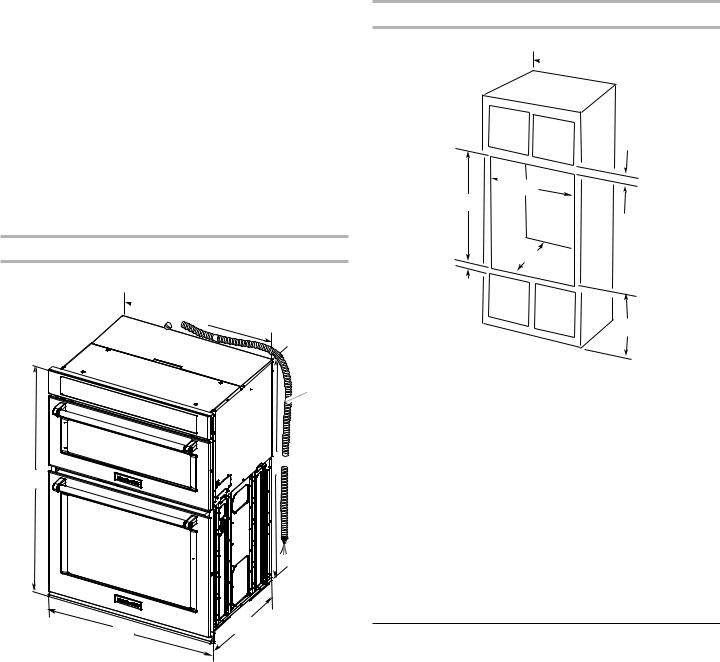
Product Dimensions
27” and 30” (68.6 cm and 76.2 cm) Ovens
 B
B
F
 C
C
A
E |
D |
|
27" (68.6 cm) models
A.429/16" (108.0 cm) overall height
B.257/16" (64.6 cm) recessed width
C.41" (104.1 cm) recessed height
D.231/4" (59.1 cm) max. recessed depth
E.27" (68.6 cm) overall width
F.48" (121.9 cm) flexible conduit length measured from the conduit clamp located at
the rear of the oven. Do not remove the conduit clamp.
30" (76.2 cm) models
A.429/16" (108.0 cm) overall height
B.287/16" (72.2 cm) recessed width
C.41" (104.1 cm) recessed height
D.231/4" (59.1 cm) max. recessed depth
E.30" (76.2 cm) overall width
F.48" (121.9 cm) flexible conduit length measured from the conduit clamp located at
the rear of the oven. Do not remove the conduit clamp.
Cabinet Dimensions
27" and 30" (68.6 cm and 76.2 cm) Ovens
 A
A 

B
 D
D
F
 G
G
E
C
27" (68.6 cm) models
A. 27" (68.6 cm) min. cabinet width
B.1" (2.5 cm) top of cutout to bottom of upper cabinet door
C.19¹/4" (48.9 cm) bottom of cutout to floor is recommended. 4"-191/4" (10.2-48.9 cm)
bottom of cutout to floor is acceptable.
D.251/2" (64.8 cm) cutout width
E.1¹/2" (3.8 cm) min. bottom of cutout to top of cabinet door
F.415/16" (105 cm)* recommended cutout height
G.24" (60.7 cm) cutout depth
30" (76.2 cm) models
A.30" (76.2 cm) min. cabinet width
B.1" (2.5 cm) top of cutout to bottom of upper cabinet door
C.191/4" (48.9 cm) bottom
of cutout to floor is recommended. 4"-191/4" (10.2-48.9 cm)
bottom of cutout to floor is acceptable.
D.281/2" (72.4 cm) cutout width
E.11/2" (3.8 cm) min. bottom of cutout to top of cabinet door
F.415/16" (105 cm)* recommended cutout height
G.24" (60.7 cm) cutout depth
*NOTE: The cutout height can be between 41" and 411/2" (104.1 cm and 105.6 cm) for microwave/oven combination.
Electrical Requirements
If codes permit and a separate ground wire is used, it is recommended that a qualified electrical installer determine that the ground path and wire gauge are in accordance with local codes.
Check with a qualified electrical installer if you are not sure the oven is properly grounded.
This oven must be connected to a grounded metal, permanent wiring system.
Be sure that the electrical connection and wire size are adequate and in conformance with the National Electrical Code, ANSI/ NFPA 70-latest edition or CSA Standards C22.1-94, Canadian Electrical Code, Part 1 and C22.2 No. O-M91-latest edition, and all local codes and ordinances.
A copy of the above code standards can be obtained from:
National Fire Protection Association 1 Batterymarch Park
Quincy, MA 02169-7471
CSA International
8501 East Pleasant Valley Road Cleveland, OH 44131-5575
3
Electrical Connection
To properly install your oven, you must determine the type of electrical connection you will be using and follow the instructions provided for it here.
■■ Oven must be connected to the proper electrical voltage, amperage, and frequency as specified on the model/serial/ rating plate. See the following illustration.
 A
A
A. Model/serial/rating plate
■■ Models rated from 7.3 to 9.6 kW at 240 V (5.4 to 7.4 kW at 208 V) require a separate 40-amp circuit. Models rated at 4.8 kW and below at 240 V (3.6 kW and below at 208 V) require a separate 30 A circuit.
■■ A circuit breaker is recommended.
■■ Connect directly to the fused disconnect (or circuit breaker box) through flexible, armored or nonmetallic sheathed, copper cable (with grounding wire). See “Make Electrical Connection” section.
■■ Flexible conduit from the oven should be connected directly to the junction box.
■■ Do not cut the conduit. The length of conduit provided is for serviceability of the oven.
■■ A UL Listed or CSA Approved conduit connector must be provided.
■■ If the house has aluminum wiring, follow the procedure below:
Connect the aluminum wiring using special connectors and/or tools designed and UL listed for joining copper to aluminum.
Follow the electrical connector manufacturer’s recommended procedure. Aluminum/copper connection must conform with local codes and industry accepted wiring practices.
For power requirements, refer to the following table.
Model |
Voltage |
Amperage |
Amperage |
Rating |
(L1)* |
(L2)* |
(W) |
||
|
|
|
|
|
KOCE507E/ |
120/240 |
32 |
30 |
8000 |
KOCE500E |
|
|
|
|
|
|
|
|
|
KOCE507E/ |
120/208 |
30 |
28 |
6600 |
KOCE500E |
|
|
|
|
*Amperage values noted above are for information purposes only: The units are rated in watts.
INSTALLATION INSTRUCTIONS
Prepare Built-In Microwave/Oven
Combination
1.Decide on the final location for the oven. Locate existing wiring to avoid drilling into or severing wiring during installation.
 WARNING
Excessive Weight Hazard
Use two or more people to move and install oven. Failure to do so can result in back or other injury.
2.To avoid floor damage, set the oven onto cardboard prior to installation. Do not use handle or any portion of the front frame for lifting.
3.Remember to remove bottom vent from the foam packing on top of oven.
4.Remove the shipping materials and tape from the oven.
5.Remove the hardware package from inside the bag containing literature.
6.Remove and set aside racks and other parts from inside the oven.
7.Move oven and cardboard close to the oven’s final location.
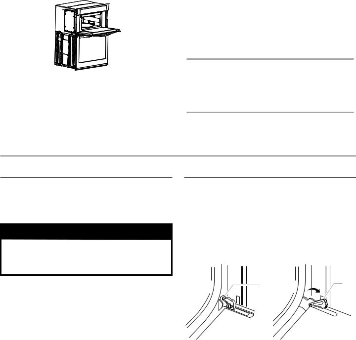
Remove Oven Door(s)
IMPORTANT: Use two hands to remove oven door.
1.Prior to removing the oven door, prepare a surface where you will place it. This surface should be flat and covered with a soft blanket, or use the corner posts from your packaging material.
2.Open the oven door.
3.Locate the oven door hinge locks in both corners of the oven door, and then rotate the hinge locks toward the oven door to the unlocked position. If the door hinge lock is not rotated fully (see illustration B), the door will not remove properly.
A |
B |
A. Oven door hinge lock in |
B. Oven door hinge lock in |
locked position |
unlocked position |
4

4.Partially close the door to engage the door latch locks. The door will stop at this point.
5.Using two hands, grasp the edges of the oven door. Lift and pull the oven door toward you and remove. You may need to gently shift door from side to side as you pull.
6.Set the oven door(s) aside on the prepared covered work surface, with the oven door resting on its handle.
7.To continue with the oven installation, go to the “Make Electrical Connection” section.
Replace Oven Door(s)
IMPORTANT: Do not replace the oven door(s) until after the oven has been installed into the cabinet.
1.Using two hands, grasp side edges of door at the midpoint. Face the oven cavity.
2.Locate the slots on each side of the oven cavity for the door hinge locks.
3.At a 45° angle, align door hinges with slots in the lower front of the oven cavity. Slowly insert door, making sure you maintain the 45° angle. You will know the door is engaged in the slot when you feel a slight drop.
4.Lower the oven door to the fully open position. If the oven door does not open to a full 90°, repeat steps 1 through 3.
5.Locate the oven door hinge locks in the corners of the oven door, and rotate the hinge locks toward the oven cavity to the locked position.
See Step 3 (illustration A) in the “Remove Oven Door(s)” section for proper locked position.
6.Close the oven door.
7.When the hinges are properly installed and the door closed, there should be an even gap between the door and the control panel. If one side of the oven door is hanging lower than the other, the hinge on that side is not properly installed.
A
A. Slot in the oven cavity for door hinge lock
5
 Loading...