


KRFF707ESS01
FRENCH DOOR BOTTOM MOUNT
REFRIGERATOR
USE & CARE GUIDE
WWW
.
KITCHENAI D
.
COM WWW
.
KITCHE NAID
.
CA
U.S.: 1-800-422-1230 C
ANAD A
: 1-800-807-6777
W10859993A

2
TABLE OF CONTENTS
Congratulations on your purchase and welcome to
the KitchenAid Brand family of high-quality
appliances. Your new KitchenAid
®
French Door
Refrigerator combines advanced cooling technology
with simple operation and high efficiency.
Each appliance that leaves our factory is inspected
thoroughly to ensure that it is working properly.
Please read the Use and Care Instructions in this guide
before operating your new refrigerator. Like all
appliances, your refrigerator may require maintenance
or repair from time to time, but you can help to ensure
that your refrigerator provides many years of reliable
service by following the instructions in this guide.
REFRIGERATOR SAFETY....................................................... 3
Proper Disposal of Your Old Refrigerator..................
............ 3
PARTS AND FEATUR
ES.......................................................... 4
What’s New Behind the Doors?............................................. 4
INSTALLATION INSTRUCTIONS............................................5
Unpack the Refrigerator......................................................... 5
- Remove the Packaging.........................................................5
- Clean
Before Using...............................................................5
Location Requirements.......................................................... 5
Remove and Replace Refrigerator Doors.............................. 6
- Remove Right-Hand Refrigerator Door................................7
- Remove Left-Hand Refrigerator Door ..................................7
- Replace Right-Hand Refrigerator Doo
r ................................8
- Replace Left-Hand Refrigerator Door...................................8
- Final Steps ............................................................................8
Remove and Replace Freezer Drawer Front ......................... 9
- Remove Drawer Front...........................................................9
- Replace Drawer Front...........................................................9
- Final Steps ............................................................................9
Electrical Requirements ....................................................... 10
Water Supply Requirements................................................10
Connect the Water Supply...................................................10
- Connect to Water Line........................................................11
- Connect to Refrigerator......................................................11
- Complete the Installation ....................................................12
Handle Installation and Removal......................................... 12
- Install Handles.....................................................................12
- Remove the Handles ........................................
..................13
Refrigerator Leveling, Door Closing and Alignment ............13
FILTERS AND ACCESSORIES..............................................15
Water Filtration System........................................................15
- Install the Water Filter.........................................................15
- The Water Filter Status Light ..............................................15
- Replace the Water Filter .....................................................16
Install Air Filter...................................................................... 16
- Installing the Air Filter..........................................................16
- Installing the Filter Status Indicator ....................................16
- Replacing the Air Filter........................................................17
Install Produce Preserver ................................................... 17
- Installing the Produce Preserver ........................................17
- Installing the Status Indicator .............................................18
- Replacing the Produce Preserver.......................................18
Accessories.......................................................................... 18
REFRIGERATOR USE.....
....................................................... 19
Opening and Closing Doors................................................. 19
Using the Controls ...............................................................19
- Viewing and Adjusting Temperature Set Points.................19
- Cooling On/Off....................................................................20
- Additional Features...............
..............................................21
Water and Ice Dispensers ....................................................22
- Flush the Water System......................................................22
- Calibrate Measured Fill .......................................................22
- The Water Dispenser...........................................................23
- The Ice Dispenser ...............
................................................24
- The Dispenser Drip Tray .....................................................24
- The Dispenser Light............................................................24
- The Dispenser Lock ............................................................24
Ice Maker and Ice Storage Bin.............................................25
- Ice Production Rate ............................................................25
- Ice Maker in the Refrigerator.............................................25
- Ice Maker in the Freezer............. .......................................25
REFRIGERATOR FEATURES ................................................26
Refrigerator Shelves .............................................................26
- Shelves and Shelf Frames ..................................................26
- Tuck Away Shelf..................................................................26
Crisper and Crisper Cover....................................................27
Temperature-Controlled Drawer..........................................27
- Preset Temperature Control ...............................................27
- Custom Temperature Control.............................................27
- Drawer Removal and Replacement......................
..............27
- Drawer Divider.....................................................................28
- Meat Storage Guide............................................................28
DOOR FEATURES..................................................................28
Door Bins..............................................................................28
FREEZER FEATURES ...............................
.............................28
Pizza Pocket and Drawer Divider.........................................28
REFRIGERATOR CARE .........................................................29
Cleaning................................................................................29
- Exterior Cleaning.................................................................29
- Interior Cleaning..........................
........................................29
- Condenser Cleaning ...........................................................30
Lights....................................................................................30
Vacation and Moving Care...................................................30
- Vacations.............................................................................30
- Moving.............
....................................................................30
TROUBLESHOOTING ............................................................31
Operation ..............................................................................31
Noise.....................................................................................32
Temperature and Moisture................................................
...33
Ice and Water .......................................................................34
Doors ....................................................................................37
PERFORMANCE DATA SHEET.............................................38
WARRANTY ............................................................................39
SERVICE NUMBERS..........................................BACK C
OVER
- Options ............................................................................20
- Remove and Replace Handle Medallions ........................13
R
EFRIGERATOR SAFETY
Proper Disposal of
Your Old Refrigerator
3
IMPORTANT: Child entrapment and suffocation are not problems
of the past. Junked or abandoned refrigerators are still dangerous
– even if they will sit for “just a few days.” If you are getting rid of
your old refrigerator, please follow these instructions to help
prevent accidents.
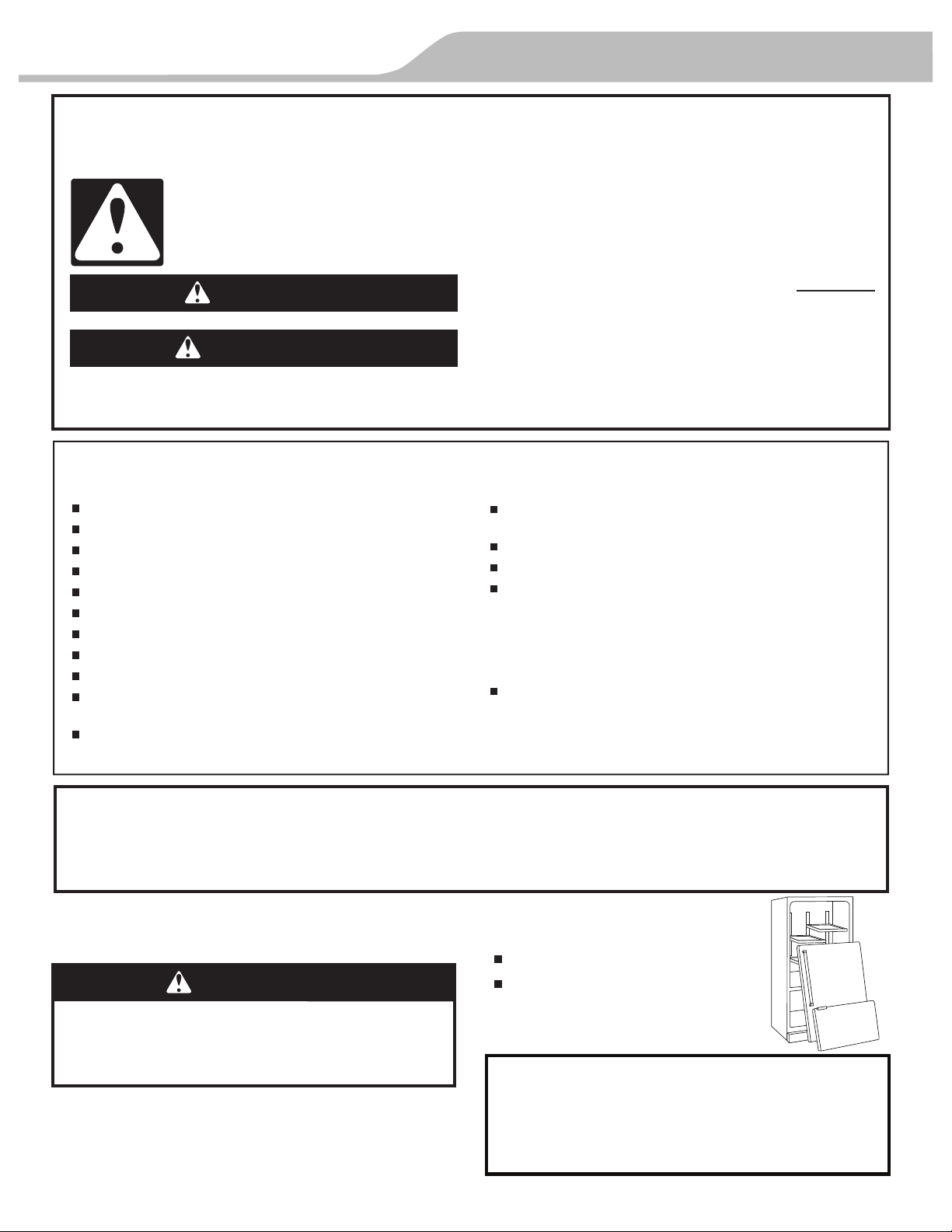
Before You Throw Away Your
Old Refrigerator or Freezer:
Take off the doors.
Leave the shelves in place so that
children may not easily climb inside.
You can be killed or seriously injured if you don't immediately
You
can be killed or seriously injured if you don't
follow
All safety messages will tell you what the potential hazard is, tell you how to reduce the chance of injury, and tell you what can
happen if the instructions are not followed.
Your safety and the safety of others are very important.
We have provided many important safety messages in this manual and on your appliance. Always read and obey all safety
messages.
This is the safety alert symbol.
This symbol alerts you to potential hazards that can kill or hurt you and others.
All safety messages will follow the safety alert symbol and either the word “DANGER” or “WARNING.”
These words mean:
follow instructions.
instructions.
DANGER
WARNING
State of California Proposition 65 Warnings:
WARNING: This product contains one or more chemicals known to the State of California to cause cancer.
WARNING: This product contains one or more chemicals known to the State of California to cause birth defects or other
reproductive harm.
WARNING
Suffocation Hazard
Remove doors from your old refrigerator.
Failure to do so can result in death or brain damage.
Important information to know about disposal of
refrigerants:
Dispose of refrigerator in accordance with Federal and Local
regulations. Refrigerants must be evacuated by a licensed,
EPA certified refrigerant technician in accordance with
established procedures.
IMPORTANT SAFETY INSTRUCTIONS
WARNING:
To reduce the risk of fire, electric shock, or injury when using your refrigerator, follow these basic precautions:
SAVE THESE INSTRUCTIONS
Plug into a grounded 3 prong outlet.
Do not remove ground prong.
Do not use an adapter.
Do not use an extension cord.
Disconnect power before servicing.
Replace all parts and panels before operating.
Remove doors from your old refrigerator.
Connect to a potable water supply only.
Use nonflammable cleaner.
Keep flammable materials and vapors, such as gasoline,
away from refrigerator.
Use two or more people to move and install refrigerator.
Disconnect power before installing ice maker (on ice maker
kit ready models only).
Use a sturdy glass when dispensing ice (on some models).
Do not hit the refrigerator glass doors (on some models).
This appliance is not intended for use by persons (including
children) with reduced physical, sensory or mental
capabilities, or lack of experience and knowledge, unless
they have been given supervision or instruction concerning
use of the appliance by a person responsible for their
safety.
Children should be supervised to ensure that they do not
play with the appliance.
4
PARTS AND FEATURES
What’s New Behind the Doors?
Your KitchenAid
®
French Door Refrigerator comes equipped with various
innovative storage and energy efficient features.
Energy and Normal Operating Sounds
Your new French Door Bottom Mount refrigerator has been
designed to optimize energy efficiency, and better regulate
temperatures to match cooling demand. You may notice that it
operates differently than your previously owned refrigerator. It is
normal for the high-efficiency compressor to run for extended
periods of time at varying speeds in order to consume only the
energy necessary for optimum efficiency. In addition, during
various stages of the cooling cycle, you may hear normal
opera
ting sounds that are unfamiliar to you.
More Storage Space
The French Door Bottom Mount has the most fresh food storage
space available, including a full-width, temperature controlled,
pantry drawer perfect for storing veggie trays or party platters.
In-Door-Ice
®
Ice Dispensing System
The ice storage bin located in the door provides an entire extra
shelf of storage space and the storage bin is removable for easy
access to filtered ice.
Dual Evaporator (on some models)
The refrigerator and freezer compartments have dedicated
evaporators to provide fresh and frozen foods with separate
climates. Frozen food stays cold and dry, while fresh food
remains at the ideal temperature and humidity.
Water Filter
NSF
®
Certified filter reduces chlorine taste and odor, particulates
(class I), lead, and mer
cury. Replacing the water filter every
6 months ensures clean, filtered drinking water.
Air Filter
An air filter is 15 times more powerful than baking soda at
reducing common food odors inside the refrigerator.
Produce Preserver (on some models)
Ethylene is a natural gas produced by fruits and vegetables to
promote ripening. The Produce Preserver absorbs ethylene, to
delay the over-ripening of fresh produce. As a result, certain
produce items will stay fresh longer.
Water Dispenser with Measured Fill
The measured fill feature allows you to dispense the desired
amount of filter
ed water.
LED Lighting
The LED lights do not ever need to be replaced.
Door Alarm
A helpful alarm sounds when the refrigerator door or freezer
drawer is left ajar.
Power Outage Indicator
If the power should go out while you are away from home, this
indicator will let you know that the refrigerator has been without
power.
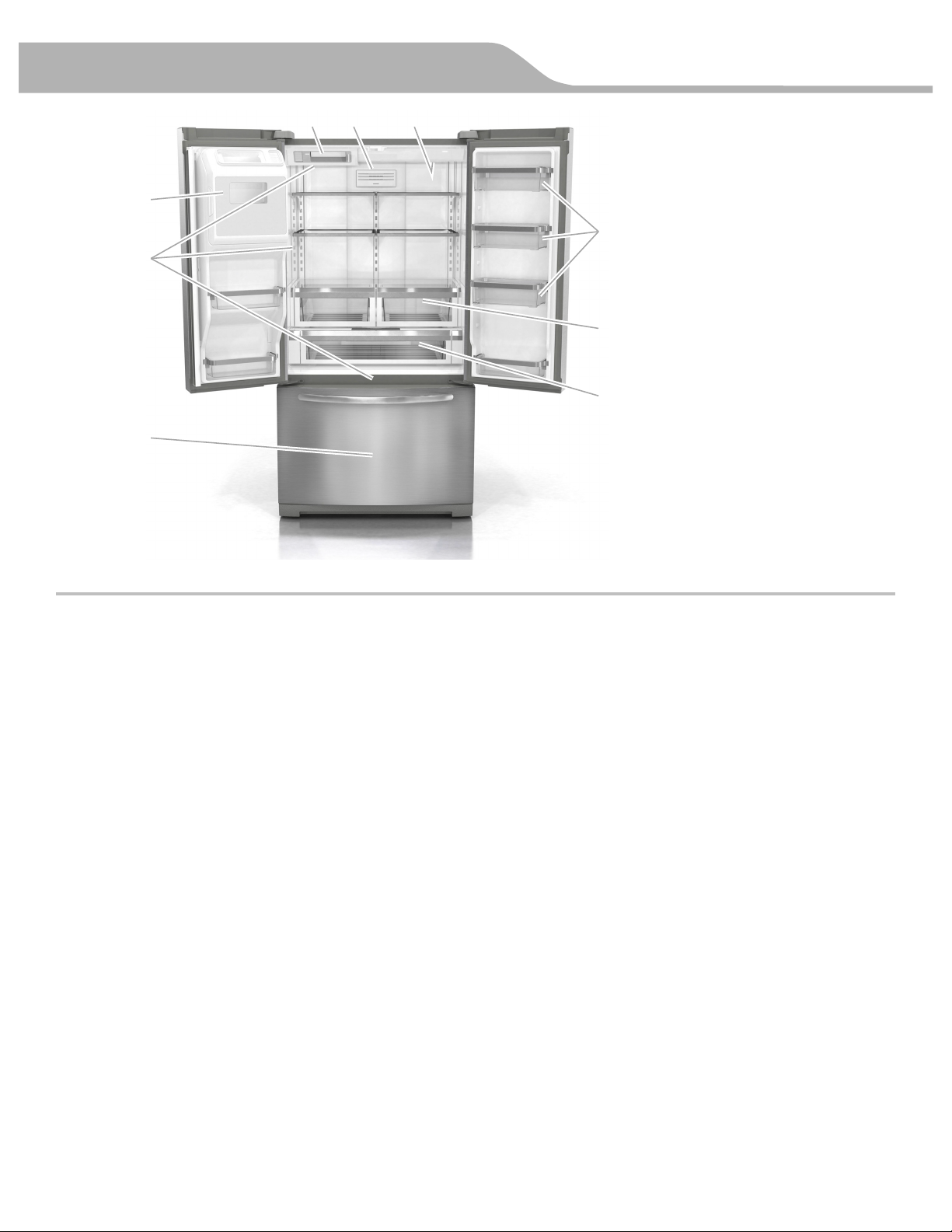
BA C
D
E
F
G
H
I
A. Ice maker
B. Air filter
C. Water filter
D. Door bins
E. Crispers
F. Pantry drawer
G. Freezer drawer
H. LED ramp-on lighting
I. In-Door-Ice
®
ice
dispensing system
Shelves with under-shelf lighting (on some models)
By moving LED lighting to a new spot under the shelves,
this leading-edge technology elevates the look and feel of
your refrigerator.
INSTALLATION INSTRUCTIONS
5
Unpack the Refrigerator
Remove the Packaging
Remove tape and glue residue from surfaces before turning
on the refrigerator. Rub a small amount of liquid dish soap
over the adhesive with your fingers. Wipe with warm water
and dry.
Do not use sharp instruments, rubbing alcohol, flammable
fluids, or abrasive cleaners to remove tape or glue. These
products can damage the surface of your refrigerator.
Dispose of/recycle all packaging materials.
Clean Before Using
After you remove all of the packaging materials, clean the inside
of your refrigerator before using it. See the cleaning instructions
in “Refrigerator Care.”
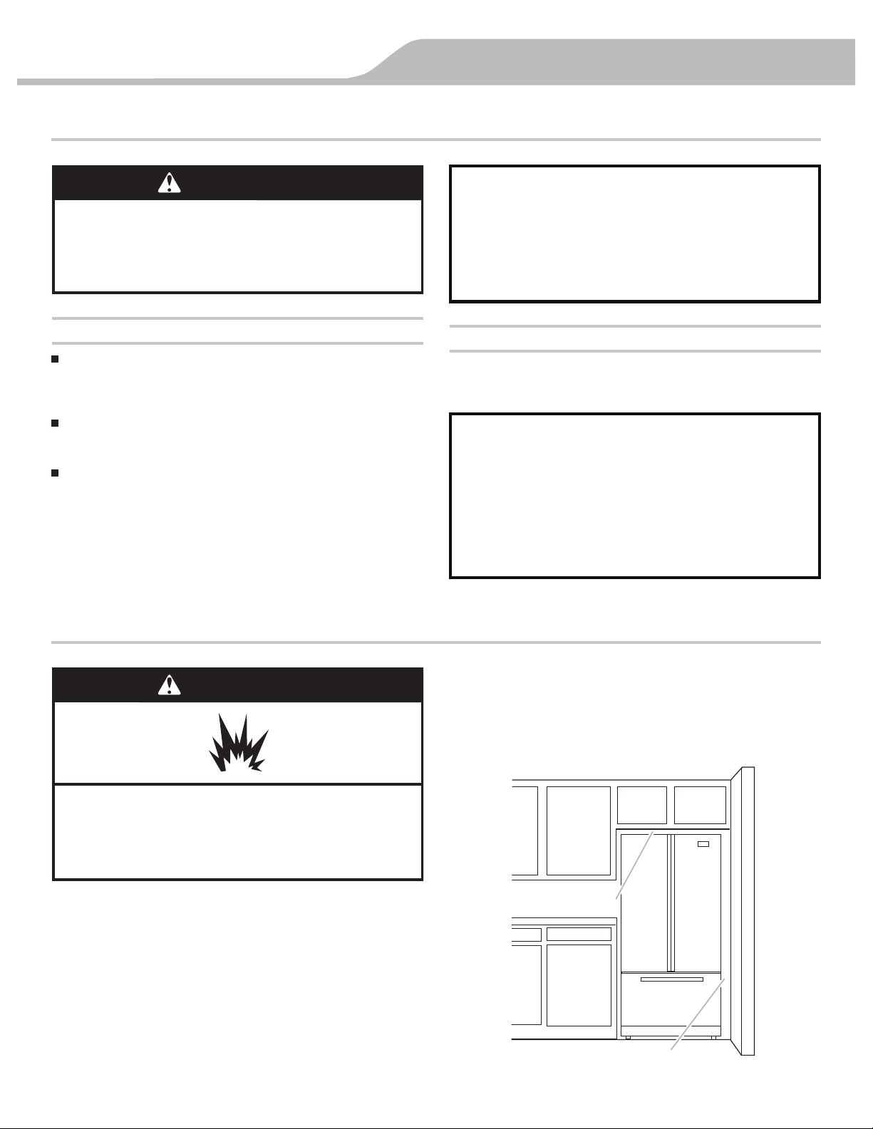
Location Requirements
IMPORTANT: This refrigerator is designed for indoor, household
use only.
To ensure proper ventilation for your refrigerator, allow for a ¹⁄₂"
(1.25 cm) of space on each side and at the top. Allow for a 1"
(2.54 cm) space behind the refrigerator. If your refrigerator has an
ice maker, allow extra space at the back for the water line
connections. When installing your refrigerator next to a fixed wall,
leave a 3³⁄₄" (9.5 cm) minimum space between the refrigerator
and wall to allow the
door to swing open.
NOTE: This refrigerator is intended for use in a locat
ion where the
temperature ranges from a minimum of 55°F (13°C) to a
maximum of 110°F (43°C). The preferred room temperature range
for optimum performance, which reduces electricity usage and
provides superior cooling, is between 60°F (15°C) and 90°F
(32°C). It is recommended that you do not install the refrigerator
near a heat source, such as an oven or radiator.
WARNING
Excessive Weight Hazard
Use two or more people to move and install
refrigerator.
Failure to do so can result in back or other injury.
When Moving Your Refrigerator:
Your refrigerator is heavy. When moving the refrigerator for
cleaning or service, be sure to cover the floor with
cardboard or hardboard to avoid floor damage. Always pull
the refrigerator straight out when moving it. Do not wiggle or
“walk” the refrigerator when trying to move it, as floor
damage could occur.
Important information to know about glass shelves
and covers:
Do not clean glass shelves or covers with warm water when
they are cold. Shelves and covers may break if exposed to
sudden temperature changes or impact, such as bumping.
Tempered glass is designed to shatter into many small,
pebble-size pieces. This is normal. Glass shelves and covers
are heavy. Use both hands when removing them to avoid
dropping.
WARNING
Explosion Hazard
Keep flammable materials and vapors, such as
gasoline, away from refrigerator.
Failure to do so can result in death, explosion, or fire.
3³⁄₄" (9.5 cm)
¹⁄₂" (1.25 cm)

6
INSTALLATION INSTRUCTIONS
Remove and Replace Refrigerator Doors
NOTE: Measure the width of your door opening, to see whether or not you need to remove the refrigerator doors to move the
refrigerator into your home. If door removal is necessary, see the following instructions.
IMPORTANT: If the refrigerator was previously installed and you are moving it out of the home, before you begin, turn the refrigerator
control OFF. Unplug the refrigerator or disconnect power. Remove food and adjustable door or utility bins from doors.
Gather the required tools and read all instructions before removing doors.
TOOLS NEEDED: ³⁄₁₆" hex-
key wrench and a #2 Phillips screwdriver
WARNING
Electrical Shock Hazard
Disconnect power before removing doors.
Failure to do so can result in death or electrical shock.
Door Removal and Replacement
Wiring Plug
Top Left Hinge
Style 1 – Water Dispenser
Tubing Connection
A
A. Outer Ring
BA
C
A. ³⁄₁₆" Internal hex-head Screws
B. Ground Wire (Do Not Remove)
C. Screws (Do Not Remove)
Style 2 – Water Dispenser
Tubing Connection
A
A. Outer Ring
Top Right Hinge
A. ³⁄₁₆"
Internal hex-head Screws
B. Hinge Cover Screw
C. Top Hinge Cover
D. Top Hinge
C
B
A
D
INSTALLATION INSTRUCTIONS
7
Remove Right-Hand Refrigerator Door
1. Unplug refrigerator or disconnect power.
2. Keep the refrigerator doors closed until you are ready to lift
them free from the cabinet.
NOTE: Provide additional support for the refrigerator door
while the hinges are being removed. Do not depend on the
door gasket magnets to hold the door in place while you are
working.
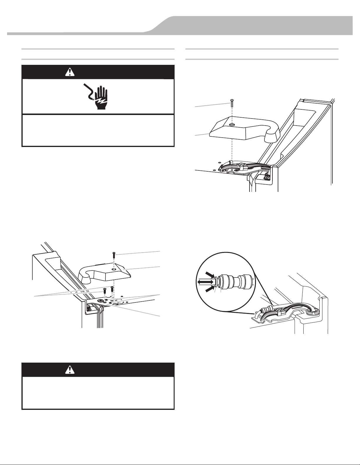
3. Using a Phillips screwdriver, remove the cover from the Top
Hinge.
4. Using the ³⁄₁₆" hex-key wrench, remove the two internal
hex-head screws from the top hinge, and set aside.
NOTE: Do not remove the two locator screws. These screws
will help you align the hinge when you replace the door.
5. Lift the refrigerator door from the bottom hinge pin. The top
hinge will com
e away with the door.
Remove Left-Hand Refrigerator Door
IMPORTANT: The tubing and wiring for the water dispenser run
through the left-hand door hinge, so they must be disconnected
before removing the door.
1. Using a Phillips screwdriver, remove the cover from the top
hinge.
2. Disconnect the water dispenser tubing located on top of the
door hinge.
Style 1 - Press the outer ring against the face of the fitting
and gently pull the dispenser tubing free.
NOTE: The water dispenser tubing remains attached to the
left-hand refrigerator door.
A. Top hinge cover screw
B. Top hinge cove
r
D. Top Hinge
E. Locator Screws
WARNING
Electrical Shock Hazard
Disconnect power before removing doors.
Failure to do so can result in death or electrical shock.
WARNING
Excessive Weight Hazard
Use two or more people to lift the refrigerator door.
Failure to do so can result in back or other injury.
A. Top hinge cover screw B. Top hinge cover
A. Outer ring
B. Face of fitting
A
B
A B
A
B
E
C
D
C. ³⁄₁₆" Internal hex-head screws
8
INSTALLATION INSTRUCTIONS
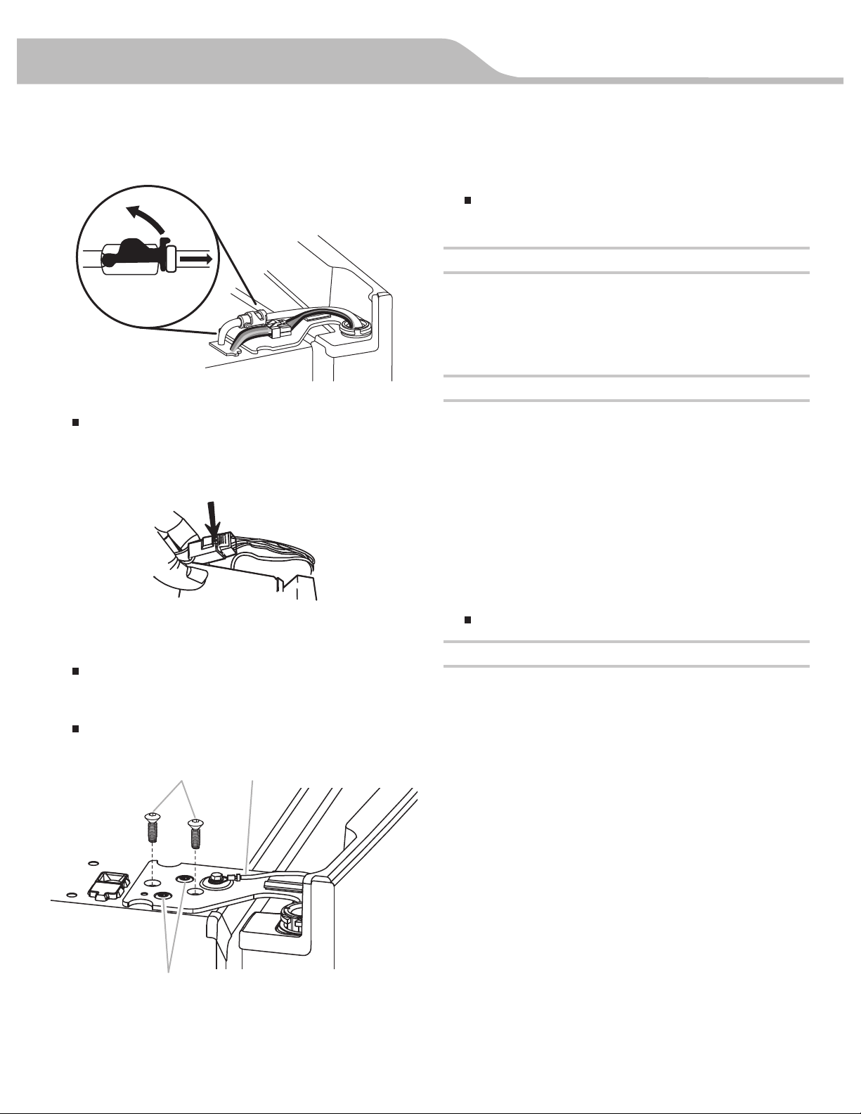
Style 2 - Firmly pull up on the clasp. Then, pull the tubing out
of the fitting.
NOTE: The water dispenser tubing remains attached to the
left-hand refrigerator door.
3. Disconnect the wiring plug located on top of the door hinge.
Grasp each side of the wiring plug. With your left thumb,
press down to release the catch and pull the sections of
the plug apart.
NOTE: Do not remove the green, ground wire. It should
remain attached to the door hinge.
4. Using the ³⁄₁₆" hex-key wrench, remove the two internal
hex-head screws from the top hinge, and set aside.
NOTES:
Provide additional support for the refrigerator door while
the hinges are being removed. Do not depend on the door
gasket magnets to hold the door in place while you are
working.
Do not remove the two locator screws. These screws will
help you align the hinge when you replace the door.
5. Lift the refrigerator door from the bottom hinge pin. The top
hinge will come away with the door.
NOTE: It may not be necessary to remove the bottom hinges
and brake feet assemblies to move the refrigerator through a
doorway.
Only if necessary, use a driver with a #2 square bit tip to
remove the bottom hinges and a ³⁄₈" nut driver to remove
the brake feet screws.
Replace Right-Hand Refrigerator Door
1. Set the right-hand door onto the bottom hinge pin.
2. Insert the top hinge pin into the open hole in the top of the
refrigerator door.
3. Using the two ³⁄₁₆" internal hex-head screws, fasten the hinge
to the cabinet. Do not tighten the screws completely.
Replace Left-Hand Refrigerator Door
IMPORTANT: Do not intertwine the water tubing and wiring
bundles when reconnecting them.
1. Set the left-hand door onto the bottom hinge pin.
2. Using the two ³⁄₁₆" internal hex-head screws, fasten the hinge
to the cabinet. Do not tighten the screws completely.
3. Reconnect the water dispenser tubing.
Style 1 - Insert the tubing into the fitting until it stops and the
outer ring is touching the face of fitting.
Style 2 - Insert the tubing firmly into the fitting until it stops.
Close the clasp around the tubing. The clasp
snaps into place
between the fitting and the collar.
4. Reconnect the electrical wi
ring.
Push together the two sections of the wiring plug.
Final Steps
1. Completely tighten the four internal hex-head screws (two on
the right-hand door hinge and two on the left-hand door
hinge).
2. Replace both top hinge covers.
A.
³⁄₁₆
" Internal hex-head screws
B. Ground wire (do not remove)
C. Locator screws
(do not remove)
A B
C
INSTALLATION INSTRUCTIONS
9
Remove and Replace Freezer Drawer Front
Depending on the width of your door opening, it may be
necessary to remove the freezer drawer front to move the
refrigerator into your home.
IMPORTANT:
If the refrigerator was previously installed and you are moving
it out of the home, before you begin, turn the refrigerator
control OFF, and unplug the refrigerator or disconnect power.
Remove food from the freezer drawer.
Two people may be required to remove and replace the
freezer drawer front.
Tool Needed: ¹⁄₄" hex driver
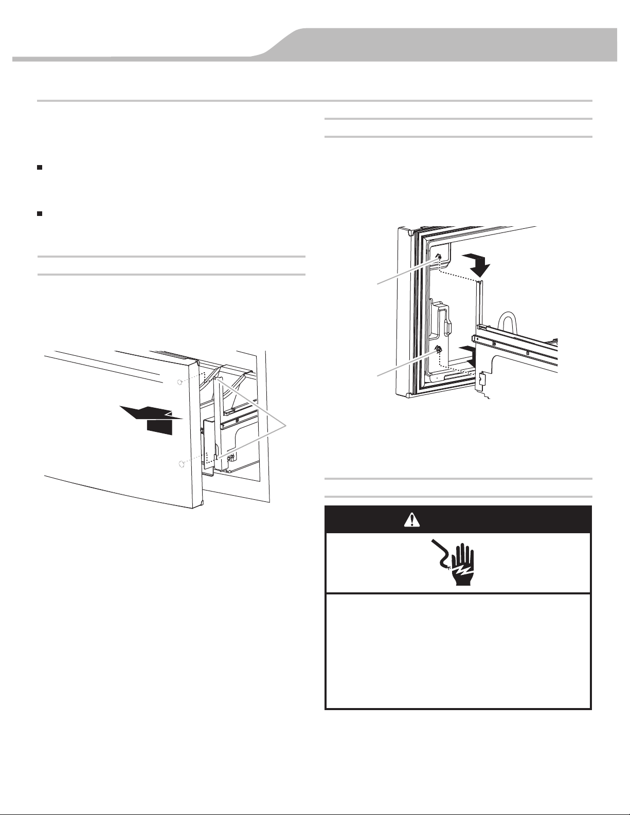
Remove Drawer Front
1. Open the freezer drawer to its full extension.
2. Remove the two screws at the top, inside the drawer front
(one on the left-hand side and one on the right-hand side)
that fasten the drawer front to the drawer glides.
3. Lift up on the drawer front to release the plastic studs from
the drawer glide bracket slots.
4. Slide the drawer glides back into the freezer.
Replace Drawer Front
1. Pull out the freezer drawer glides to their full extension.
2. Holding the drawer front by its sides, align the two plastic
studs, located at the bottom, inside the drawer front, with the
drawer glide bracket slots.
NOTE: It helps if one person holds the drawer glides steady
while another person aligns the drawer front and inserts the
studs into the slots.
3. Replace and tighten the two screws at the top of the drawer
front (one on the left-hand side and one on the right-hand
side).
Final Steps
1. Plug into a grounded 3 prong outlet.
2. Reset the controls. See “Using the Controls.”
3. Return all removable door parts to doors and the food to
refrigerator.
A. Drawer glide bracket slots
A. Drawer front screw
B. Drawer front plastic stud
A
B
Electrical Shock Hazard
Plug into a grounded 3 prong outlet.
Do not remove ground prong.
Do not use an adapter.
Do not use an extension cord.
Failure to follow these instructions can result in death,
fire, or electrical shock.
WARNING
A
10
INSTALLATION INSTRUCTIONS
Electrical Requirements
Before you move your refrigerator into its final location, it is
important to make sure you have the proper electrical
connection.
Recommended Grounding Method
A 115 volt, 60 Hz, AC only 15- or 20-amp fused, grounded
electrical supply is required. It is recommended that a separate
circuit serving only your refrigerator be provided. Use an outlet
that cannot be turned off by a switch. Do not use an
extension cord.
NOTE: Before performing any type of installation, cleaning, or
removing a light bulb, turn Cooling OFF, and then di
sconnect the
refrigerator from the electrical source. When you have finished,
reconnect the refrigerator to the electrical source and turn
Cooling ON. See “Using the Controls.”
Water Supply Requirements
A cold water supply with water pressure between 35 and 120 psi
(241 and 827 kPa) is required to operate the water dispenser and
ice maker. If you have questions about your water pressure, call a
licensed, qualified plumber.
NOTE: If the water pressure is less than what is required, the flow
of water from the water dispenser could decrease or ice cubes
could be hollow or irregular shaped.
Reverse Osmosis Water Supply
IMPORTANT: The pressure of the water supply coming out of a
reverse osmosis system going to the water inlet valve of the
refrigerator needs to be between 35 and 120 psi (241 and
827 kPa).
If a reverse osmosis water filtration system is connected to your
cold water supply, the water
pressure to the reverse osmosis
system needs to be a minimum of 40 to 60 psi (276 to 414 kPa).
Check to see whether the sediment filter in the reverse
osmosis system is blocked. Replace the filter if necessary.
Allow the storage tank on the reverse osmosis system to refill
after heavy use. The tank capacity could be too small to keep
up with the requirements of the refrigerator.
NOTE: Faucet mounted reverse osmosis systems are not
recommended.
If your refrigerator has a water filter, it may further reduce the
water pressure when used in conjunction with a reverse
osmosis system. Remove the water filter. See “Water
Filtration System.”
If you have questions about your water pressure, call a licensed,
qualified plumber.
Connect the Water Supply
Read all directions before you begin.
IMPORTANT:
Plumbing shall be installed in accordance with the
International Plumbing Code and any local codes and
ordinances.
The gray water tubing on the back of the refrigerator (which is
used to connect to the household water line) is a PEX
(cross-linked polyethylene) tube. Copper and PEX tubing
connections from the household water line to the refrigerator
are acceptable, and will help avoid off-taste or odor in your
ice or water. Check for leaks.
If PEX tubing is used instead of copper, we recommend the
following Whirlpool Part Numbers:
W10505928RP (7 ft [2.14 m] jacketed PEX
),
8212547RP (5 ft [1.52 m] PEX), or
W10267701RP (25 ft [7.62 m] PEX).
Install tubing only in areas where temperatures will remain
above freezing.
TOOLS NEEDED:
Gather the required tools and parts before starting installation.
Flat-blade screwdriver
⁷⁄₁₆" and ¹⁄₂" open-end wrenches or two adjustable wrenches
¹⁄₄" nut driver
NOTE: Do not use a piercing-type or ³⁄₁₆" (4.76 mm) saddle valve
which reduces water flow and clogs easier.
Electrical Shock Hazard
Plug into a grounded 3 prong outlet.
Do not remove ground prong.
Do not use an adapter.
Do not use an extension cord.
Failure to follow these instructions can result in death,
fire, or electrical shock.
WARNING

INSTALLATION INSTRUCTIONS
11
Connect to Water Line
IMPORTANT: If you turn the refrigerator on before the water is
connected, turn the ice maker OFF.
1. Unplug refrigerator or disconnect power.
2. Turn OFF main water supply. Turn ON nearest faucet long
enough to clear line of water.
3. Use a quarter-turn shutoff valve or the equivalent, served by
NOTE: To allow sufficient water flow to the refrigerator, a
minimum ¹⁄₂" size household supply line is recommended.
4. Now you are ready to connect the copper tubing to the
shutoff valve. Use ¹⁄₄" (6.35 m
m) OD soft copper tubing to
connect the shutoff valve and the refrigerator.
Ensure that you have the proper length needed for the
job. Be sure both ends of the copper tubing are cut
square.
Slip compression sleeve and compression nut onto
copper tubing as shown. Insert end of tubing into outlet
end squarely as far as it will go. Screw compression nut
onto outlet end with adjustable wrench. Do not
overtighten.
5. Place the free end of the tubing into a container or sink, and
turn on main water supply to flush out tubing until water is
clear. Turn OFF shutoff valve on the water pipe.
NOTE: Always drain the water line before making the final
connection to the inlet of the water valve to avoid possible
water valve malfunction.
6. Bend the copper tubing to meet the water line inlet, which is
located on the ba
ck of the refrigerator cabinet as shown.
Leave a coil of
copper tubing to allow the refrigerator to be
pulled out of the cabinet or away from the wall for service.
Connect to Refrigerator
Follow the connection instructions specific to your model.
Style 1
1. Remove plastic cap from water valve inlet port. Attach the
copper tube to the valve inlet using a compression nut and
sleeve as shown. Tighten the compression nut. Do not
overtighten. Confirm copper tubing is secure by pulling on
copper tubing.
2. Create a service loop with the copper tubing. Avoid kinks
when coiling the copper tubing. Secure copper tubing to
refrigerator cabinet with a “P” clamp.
3. Turn on water supply to refrigerator and check for leaks.
Correct any leaks.
Style 2
1. Unplug refrigerator or disconnect power.
2. Remove and discard the short, black plastic part from the
end of the water line inlet.
3. Thread the nut onto the end of the tubing. Tighten the nut by
hand. Then tighten it with a wrench two more turns. Do not
overtighten.
NOTE: To avoid rattling, be sure the copper tubing does not
touch the cabinet’s side wall or other parts inside the cabinet.
A. Sleeve
B. Nut
C. Copper tubing (to refrigerator)
D. Household supply line (½" minimum)
A. Compression sleeve
B. Compression nut
C. Copper tubing
A
B
D
C
B CA
A. Copper tubing
B. “P” clamp
C. Compression nut
D. Compression sleeve
A. Household water line
B. Nut (purchased)
C. Ferrule (purchased)
D. Refrigerator water tubing
B
A
C
D
D
A B C
a ¹⁄₂" household supply line.
12
INSTALLATION INSTRUCTIONS
4. Install the water supply tube clamp around the water supply
line to reduce strain on the coupling.
5. Turn shutoff valve ON.
6. Check for leaks. Tighten any connections (including
connections at the valve) or nuts that leak.
7. On some models, the ice maker is equipped with a built-in
water strainer. If your water conditions require a second water
strainer, install it in the ¹⁄₄" (6.35 mm) water line at either tube
connection. Obtain a water strainer from your appliance
dealer.
Complete the Installation
1. Plug into a grounded 3 prong outlet.
2. Flush the water system. See “Water and Ice Dispensers.”
NOTE: Allow 24 hours to produce the first batch of ice. Discard
the first three batches of ice produced. Allow 3 days to
completely fill the ice storage bin.
Handle Installation and Removal
Parts Included: Door handles (2), Drawer handle(s) (1 or 2
depending on model), ¹⁄₈" hex key, spare setscrew(s)
NOTE: With the handles laying on a flat surface, the handles
intended for the drawers are more curved. They will not mount
flush against the doors.
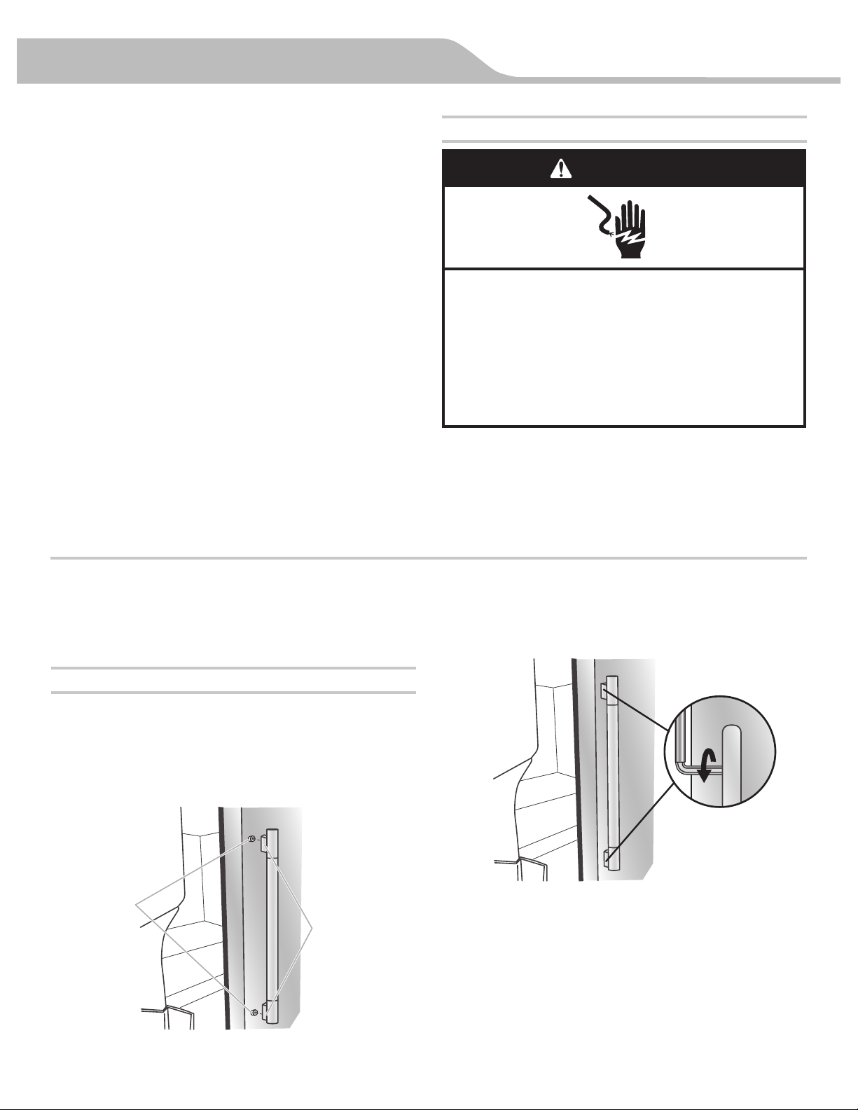
Install Handles
NOTE: Handle mounting setscrews are preinstalled inside the
handle.
1. Remove the handles from the packaging inside the
refrigerator, and place them on a soft surface.
2. Open a refrigerator compartment door. On the closed door,
place a handle onto the shoulder screws so that the
setscrews are facing the adjacent door.
3. Firmly push the handle toward the door until the handle base
is flush against the door.
4. While holding the handle, insert the short end of the hex key
into the upper
hole and slightly rotate the hex key until it is
engaged in the setscrew.
5. Using a
clockwise motion tighten the setscrew just until it
begins to contact the shoulder screw. Do not fully tighten.
6. Repeat steps 4 and 5 to fasten the lower setscrew.
7. Once both setscrews have been partially tightened as
instructed in the previous steps, fully tighten both setscrews.
IMPORTANT: When the screws feel tight, tighten them an
additional quarter-turn. The handle is not properly installed
without this extra tighteni
ng.
Electrical Shock Hazard
Plug into a grounded 3 prong outlet.
Do not remove ground prong.
Do not use an adapter.
Do not use an extension cord.
Failure to follow these instructions can result in death,
fire, or electrical shock.
WARNING
A. Shoulder screws
B. Setscrews inside the handle
A
B
INSTALLATION INSTRUCTIONS
13
8. Repeat steps 2 through 7 to install the other handle onto the
adjacent refrigerator door.
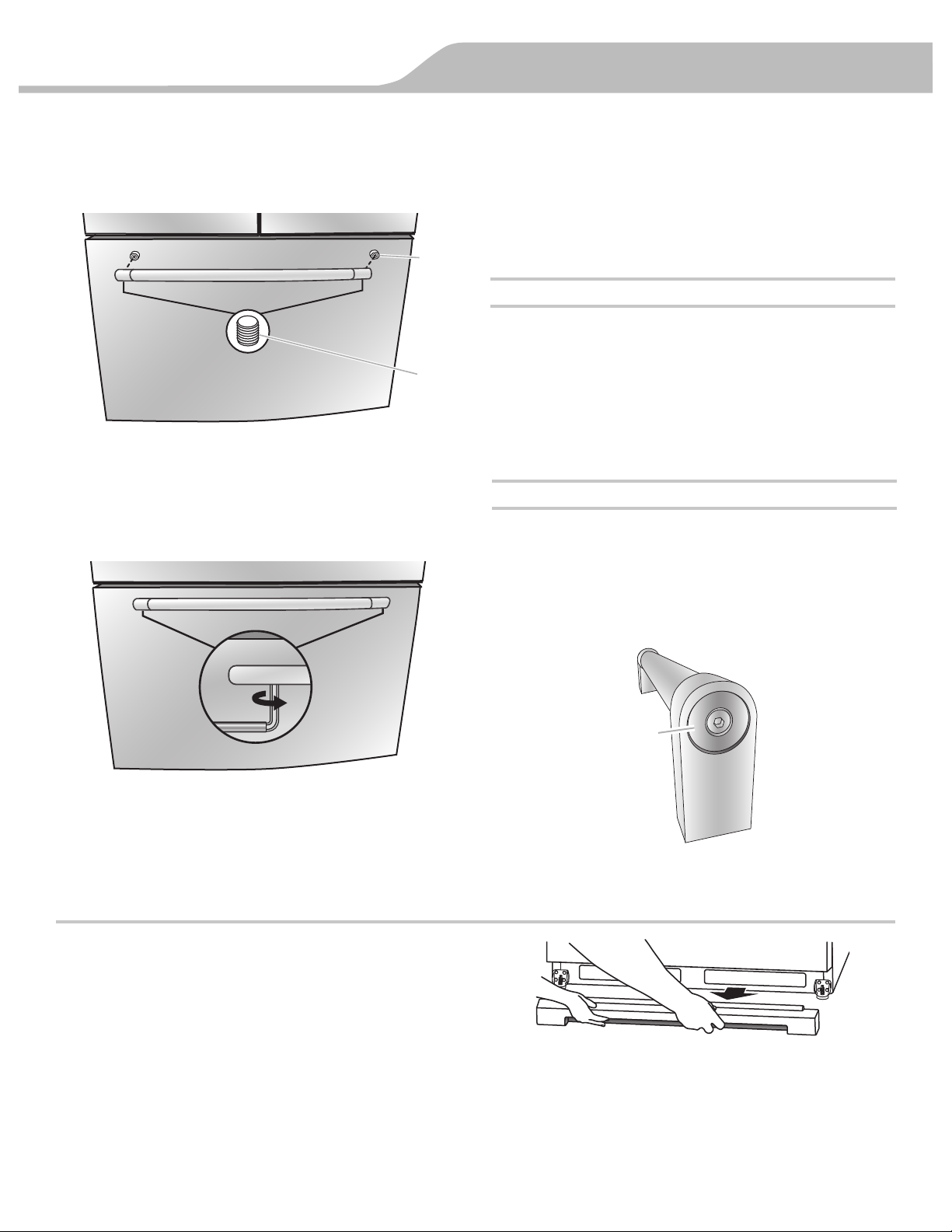
9. With the drawer(s) closed, place the handle onto the shoulder
screws so that the setscrews are facing down toward the
floor.
10. Firmly push the handle toward the drawer until the handle
base is flush against the drawer.
11. Insert the short end of the hex key into the left-hand hole and
slightly rotate the hex key until it is engaged in the setscrew.
12. Using a left to right motion tighten the setscrew a quarter-turn
at a time just until
it begins to contact the shoulder screw. Do
not fully tighten.
13.
Repeat steps 11 and 12 to fasten the right-hand setscrew to
the shoulder screw.
14. Once both setscrews have been partially tightened as
instructed in the previous steps, fully tighten both setscrews.
IMPORTANT: When the screws feel tight, tighten them an
additional quarter-turn. The handle is not properly installed
without this extra tightening.
15. For some models, repeat steps 9 through 14 to install a
handle on the second drawer.
16. Save the hex
key and all instructions.
Remove the Handles
1. While holding the handle, insert the short end of the hex key
into a setscrew hole and slightly rotate the hex key until it is
engaged in the setscrew.
2. Using a right to left motion loosen the setscrew a quarter-turn
at a time.
3. Repeat steps 1 and 2 for the other setscrew. Slowly pull the
handle away from the door or drawer.
4. If necessary, use a Phillips screwdriver to remove the
shoulder screws from the door.
Refrigerator Leveling, Door Closing and Alignment
The base grille covers the adjustable brake feet and roller
assemblies located at the bottom of the refrigerator below the
freezer drawer. Before making any adjustments, remove the base
grille and move the refrigerator to its final location.
Tools Needed: ¹⁄₄" hex driver
Tools Provided: ¹⁄₈" hex-key wrench
1. Remove the base grille. Grasp the grille firmly and pull it
toward you. Open the freezer drawer to access the brake
feet.
NOTE: To allow the refrigerator to roll easier, raise the break
feet by turning them counterclockwise.
The front rollers will
be touching the floor.
2. Move the refrigerator to its final location.
3. Lower the brake feet, by turning them clockwise, until the
rollers are off the floor and both brake feet are snug against
the floor. This keeps the refrigerator from rolling forward when
opening the refrigerator doors or freezer drawer.
IMPORTANT: If you need to make further adjustments
involving the brake feet, you must turn both brake feet the
same amount to keep the refrigerator level.
A. Shoulder screw
B. Setscrews inside
the handle
A
B
Remove and Replace Handle Medallions (optional)
The handles for your model have red medallions on the ends.
Replacement medallions are available for purchase. See
“Accessories” to order.
1. Using a ¹⁄₈" hex key, remove the medallion from the end of
the handle.
2. Replace medallion.
3. Using the fastener removed in Step 1, attach the medallion
to the handle.
A
A. Handle medallion
 Loading...