


INSTALLATION INSTRUCTIONS 27" (68.6 CM) AND 30" (76.2 CM) ELECTRIC BUILT-IN MICROWAVE OVEN FLUSH INSTALLATION KIT
INSTRUCTIONS D’INSTALLATION POUR ENSEMBLED’INSTALLATION EN AFFLEUREMENT DE FOUR ÀMICRO-ONDES ÉLECTRIQUE ENCASTRÉ DE 27" (68,6 CM) ET 30" (76,2 CM)
Flush Installation Kit Part Number |
Size and Color |
UL Listed for Model Numbers |
Ensemble d’installation en |
Dimensions et couleur |
Homologation UL pour les |
affleurement référence |
|
modèles numéro |
|
|
|
W10752698 |
27" (68.6 cm), stainless steel |
KMBP107ESS |
|
27" (68,6 cm), acier inoxydable |
|
|
|
|
W10839401 |
27" (68.6 cm), limited edition black |
KMBP107EBS |
|
27" (68,6 cm), edition limitee en noir |
|
|
|
|
W10752697 |
30" (76.2 cm), stainless steel |
KMBP100ESS |
|
30" (76,2 cm), acier inoxydable |
|
|
|
|
W10839402 |
30" (76.2 cm), limited edition black |
KMBP100EBS |
|
30" (76,2 cm), édition limitée en noir |
|
|
|
|
Table of Contents/Table des matières
BUILT-IN MICROWAVE OVEN SAFETY................................... |
2 |
INSTALLATION REQUIREMENTS .......................................... |
2 |
Tools and Parts .................................................................... |
2 |
Location Requirements ........................................................ |
2 |
INSTALLATION INSTRUCTIONS ........................................... |
4 |
Assemble Spacer Kit............................................................. |
4 |
Install Spacer Kit................................................................... |
4 |
Install Microwave Oven......................................................... |
4 |
Complete Installation ........................................................... |
4 |
SÉCURITÉ DU FOUR À MICRO-ONDES ENCASTRÉ............ |
5 |
EXIGENCES D’INSTALLATION ............................................... |
5 |
Outillage et pièces................................................................ |
5 |
Exigences d’emplacement.................................................... |
5 |
INSTRUCTIONS D’INSTALLATION......................................... |
7 |
Assemblage de la trousse d’entretoise................................. |
7 |
Installation de la trousse d’entretoise................................... |
7 |
Installation du four à micro-ondes........................................ |
7 |
Achever l’installation............................................................. |
7 |
IMPORTANT:
Save for local electrical inspector's use.
IMPORTANT :
À conserver pour consultation par l'inspecteur local des installations électriques.
W10892289A

BUILT-IN MICROWAVE OVEN SAFETY
Your safety and the safety of others are very important.
many important safety messages in this manual and on your appliance. Always read and obey all safety
safety alert symbol.
alerts you to potential hazards that can kill or hurt you and others.
messages will follow the safety alert symbol and either the word “DANGER” or “WARNING.”
mean:
 DANGER
  WARNING
You can be killed or seriously injured if you don't immediately follow instructions.
You can be killed or seriously injured if you don't follow instructions.
All safety messages will tell you what the potential hazard is, tell you how to reduce the chance of injury, and tell you what can happen if the instructions are not followed.
INSTALLATION REQUIREMENTS
Tools and Parts
Gather the required tools and parts before starting installation. Read and follow the instructions provided with any tools listed here.
Tools Needed
■■ |
Phillips screwdriver |
■■ |
Level |
■■ ¼" (6 mm) nut driver |
■■ |
Drill |
|
■■ |
Measuring tape |
■■ ¹⁄8" (3 mm) drill bit |
|
Parts Needed
■■ (2) Spacer bars - included with built-in microwave oven
■■ (4) Hex-head washer screws - included with built-in microwave oven
■■ (4) Pan-head screws - included with built-in microwave oven
Parts Supplied
■■ Bottom vent
Location Requirements
IMPORTANT: Observe all governing codes and ordinances.
■■ Cabinet opening dimensions that are shown must be used. Given dimensions provide minimum clearance with microwave oven.
■■ Recessed installation area must provide complete enclosure around the recessed portion of the microwave oven.
■■ Microwave oven support surface must be solid, level, and flush with bottom of cabinet cutout. Floor must be able to support a weight of 90 lbs (41.0 kg).
IMPORTANT: To avoid damage to your cabinets, check with your builder or cabinet supplier to make sure that the materials used will not discolor, delaminate, or sustain other damage. This oven has been designed in accordance with the requirements of UL and CSA International and complies with the maximum allowable wood cabinet temperatures of 194°F (90°C).
Bottom Vent Dimensions
A
|
|
|
|
27" (68.6 cm) Models |
30" (76.2 cm) Models |
||
A. 26³⁄4" (67.9 cm) overall width |
A. 29³⁄4" (75.6 cm) overall width |
||
2
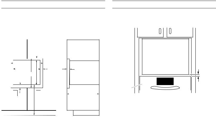
Cabinet Dimensions - Flush Installation
A 23¹⁄4" (59.0 cm) minimum cutout depth is required. These dimensions will result in a ¹⁄4" (6 mm) reveal on the top, a
¹⁄4" (6 mm) reveal on the sides, and a ¹⁄8" (3 mm) reveal on the bottom of the microwave oven. The front face of the cleats and platform will be visible and should be treated as a finished surface.
|
|
Front View |
|
|
Side View |
|||||||||
|
|
|
|
|
|
|
A |
|
|
|
|
|
|
|
|
|
B |
|
|
|
|
|
|
|
|
|
|
|
|
|
|
C |
|
|
|
|
F |
|
|
K |
||||
|
|
|
|
|||||||||||
|
|
|
|
|
|
|
|
|
|
|
|
|
|
|
|
|
|
|
D |
E |
|
|
|
|
|
|
|
||
|
H |
G |
|
H |
|
|
|
J |
|
|
||||
|
|
|
|
|
||||||||||
|
|
|
|
|
|
|
|
|
|
|
||||
|
|
|
|
|
|
|
|
|
|
|
|
|
|
|
|
|
|
|
|
I |
|
|
|
|
|
|
|
|
|
27" (68.6 cm) Models |
|
|
|
30" (76.2 cm) Models |
||||||||||
A. |
5⁄8" (16 mm) top cleat* |
A. |
5⁄8" (16 mm) top cleat* |
|||||||||||
B. 27¹⁄4" (69.2 cm) minimum width |
B. 30¹⁄4" (76.8 cm) minimum width |
|||||||||||||
|
of flush inset cutout |
|
|
|
|
of flush inset cutout |
||||||||
C. 257⁄8" (65.7 cm) minimum width |
C. 287⁄8" (70.8 cm) minimum width |
|||||||||||||
|
of opening |
|
|
|
|
of opening |
||||||||
D. 19" (48.3 cm) minimum height |
D. 19" (48.3 cm) minimum height |
|||||||||||||
|
of flush inset cutout |
|
|
|
|
of flush inset cutout |
||||||||
E. |
175⁄8" (44.7 cm) recommended |
E. |
175⁄8" (44.7 cm) recommended |
|||||||||||
|
cutout height |
|
|
|
|
cutout height |
||||||||
F. |
¹¹⁄16" (17 mm) side cleat* |
F. |
¹¹⁄16" (17 mm) side cleat* |
|||||||||||
G. ³⁄4" (19 mm) bottom cleat* |
G. ³⁄4" (19 mm) bottom cleat* |
|||||||||||||
H. Recommended junction box |
H. Recommended junction box |
|||||||||||||
|
location |
|
|
|
|
|
|
|
|
location |
||||
I. |
40" (101.6 cm) bottom of |
I. |
40" (101.6 cm) bottom of |
|||||||||||
|
cutout to floor (recommended) |
|
cutout to floor (recommended) |
|||||||||||
J. 23¹⁄4" (59.0 cm) minimum |
J. 23¹⁄4" (59.0 cm) minimum |
|||||||||||||
|
depth of cutout |
|
|
|
|
depth of cutout |
||||||||
K. 1³⁄8" (3.5 cm) recess from front |
K. 1³⁄8" (3.5 cm) recess from front |
|||||||||||||
|
of cabinet |
|
|
|
|
of cabinet |
||||||||
*Cleats must be recessed 1³⁄8" (3.5 cm) from the front of the cabinet.
Minimum Installation Clearances
For proper installation, the following minimum clearances must exist below the cabinet opening.
Installation Above Single Built-In Oven
A 
C
B
A.Upper cabinet
B.Lower single oven*
C.1" (2.5 cm) from top of oven
*Approved models: KMBP107ESS, KMBP100ESS, KMBP100EBS, KMBP107EBS
3
 Loading...