

KitchenAid KOCE900HSS00, KOCE900HSS01, KOCE900HSS02, KOCE900HBS01, KOCE900HBS02 Installation Guide [en, fr]
...Page 1

INSTALLATION INSTRUCTIONS 30" (76.2CM)
IMPORTANT:
Sa
IMPOR
À conser
.
ELECTRIC BUILT-IN MICROWAVE/OVEN
COMBINATION
INSTRUCTIONS D’INSTALLATION DES
ENSEMBLES FOURS ÉLECTRIQUES/FOURS
À MICRO-ONDES ENCASTRÉS DE 30 PO
(76,2CM)
Table of Contents/Table des matières
BUILT-IN OVEN SAFETY ................................................................2
INSTALLATION REQUIREMENTS
Tools and Parts
Built-In Microwave/Oven Combination Location Requirements
Electrical Requirements
INSTALLATION INSTRUCTIONS
Prepare Built-In Oven
Remove Oven Door(s)
Replace Oven Door(s)
Make Electrical Connection
Install Oven
Complete Installation
.............................................................................2
...............................................................4
...................................................................5
..................................................................5
..................................................................6
...................................................................................8
...................................................................9
.................................................2
.3
...................................................5
.........................................................7
SÉCURITÉ DU FOUR ENCASTRÉ
EXIGENCES D’INSTALLATION
Outils et pièces
Exigences d’emplacement pour ensemble four/four à
micro-ondes encastré
Spécifications électriques
INSTRUCTIONS D’INSTALLATION
Préparer le four encastré
Enlever la ou les portes du four
Réinstaller la ou les portes du four
Raccordement électrique
Installer le four
Terminer l’installation
...........................................................................10
................................................................10
............................................................13
...........................................................15
............................................................................17
..................................................................18
..............................................10
...................................................10
..........................................................12
.............................................13
.................................................13
............................................14
ve for local electrical inspector's use.
W11047062B
TANT :
ver pour consultation par l'inspecteur local des installations électriques
Page 2
BUILT-IN OVEN SAFETY
Your safety and the safety of others are very important.
We have provided many important safety messages in this manual and on your appliance. Always read and obey all safety
messages.
This is the safety alert symbol.
This symbol alerts you to potential hazards that can kill or hurt you and others.
All safety messages will follow the safety alert symbol and either the word “DANGER” or “WARNING.”
These words mean:
You can be killed or seriously injured if you don't immediately
DANGER
WARNING
All safety messages will tell you what the potential hazard is, tell you how to reduce the chance of injury, and tell you what can
happen if the instructions are not followed.
follow instructions.
You
can be killed or seriously injured if you don't
instructions.
INSTALLATION REQUIREMENTS
Tools and Parts
Gather the required tools and parts before starting
installation.Read and follow the instructions provided
withanytools listed here.
Tools Needed
■ Phillips screwdriver
■ Measuring tape
■ Hand or electric drill (for wall cabinet installations)
■ 1" (2.5 cm) drill bit (for wall cabinet installations)
■ Level
■ Flat-blade screwdriver
Parts Needed
■ UL Listed or CSA Approved conduit connector
■ UL Listed wire connectors
■ Warming Drawer Deector Kit (for ovens installed
aboveawarming drawer)
Order Part Number W10489569 for stainless steel
30" (76.2cm) kit
Order Part Number W10727416 for black stainless steel
30" (76.2 cm) kit
To order, see the “Assistance or Service” section
oftheUseand Care Guide.
■ Flush Installation Kit (for Combo installed at ush installation)
Order Part Number W10752693 for stainless steel
30" (76.2 cm) kit
Order Part Number W10752691 for black stainless steel
30" (76.2 cm) kit
To order, see the “Assistance or Service” section of the Use
and Care Guide.
Parts Supplied
■ #8-14 x 1" (2.5 cm) screws (4)
■ Bottom vent
■ #8-18 x
Check local codes. Check existing electrical supply. Seethe
“Electrical Requirements” section.
It is recommended that all electrical connections
bemadebyalicensed, qualied electrical installer.
3
/8" (9.5 mm) screws - bottom vent (2)
follow
2
Page 3
Built-In Microwave/Oven Combination
A
F
Location Requirements
IMPORTANT: Observe all governing codes and ordinances.
■ Cabinet opening dimensions that are shown must be used.
Given dimensions provide minimum clearance with oven.
■ Recessed installation area must provide complete enclosure
around the recessed portion of the oven.
■ Grounded electrical supply is required. See the “Electrical
Requirements” section.
■ Electrical supply junction box should be located 3" (7.6cm)
maximum below the support surface when the oven is
installed in a wall cabinet. A 1" (2.5 cm) minimum diameter
hole should have been drilled in the left rear corner of the
support surface to pass the appliance cable through to the
junction box.
■ Oven support surface must be solid, level and ush with
bottom of cabinet cutout. Floor must be able to support a
total weight (microwave and built-in oven) of 300 lbs (136 kg)
for 30" (76.2 cm) models.
IMPORTANT: To avoid damage to your cabinets, check
with your builder or cabinet supplier to make sure that the
materials used will not discolor, delaminate or sustain other
damage. This oven has been designed in accordance with
the requirements of UL and CSA International and complies
with the maximum allowable wood cabinet temperatures of
194°F (90°C).
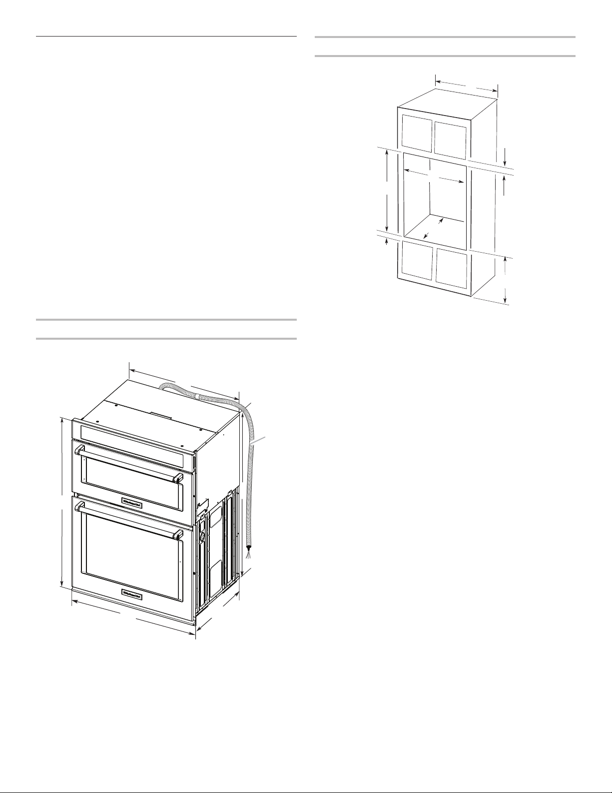
Product Dimensions
30" (76.2 cm) Ovens
B
Cabinet Dimensions
30" (76.2 cm) Ovens
A
B
D
F
G
E
C
30" (76.2 cm) models
A. 30" (76.2 cm) min. cabinet width
B. 1" (2.5 cm) top of cutout to bottom
of upper cabinet door
C. 191/4" (48.9 cm) bottom of cutout to
oor is recommended.
4"-191/4" (10.2-48.9 cm) bottom of
cutout to oor is acceptable.
D 281/2" (72.4 cm) cutout width
E. 11/2" (3.8 cm) min. bottom of cutout
to top of cabinet door
F. 415/16" (105 cm)* recommended
cutout height
G. 24" (60.7 cm) cutout depth
* NOTE: The cutout height can be between 41" and 411/2"
(104.1 cm and 105.6 cm) for microwave/oven combination.
C
E
30" (76.2 cm) models
A. 429/16" (108.0 cm) overall height
B. 287/16" (72.2 cm) recessed width
C. 41" (104.1 cm) recessed height
D. 231/4" (59.1 cm) max. recessed
depth
E. 30" (76.2 cm) overall width
F. 48" (121.9 cm) exible conduit
length measured from the
conduit clamp located at the
rear of the oven. Do not remove
the conduit clamp.
D
3
Page 4
Electrical Requirements
If codes permit and a separate ground wire is used, it is
recommended that a qualied electrical installer determine
thatthe ground path and the wire gauge are in accordance
withlocal codes.
Check with a qualied electrical installer if you are not
suretheoven is properly grounded.
This oven must be connected to a grounded metal,
permanentwiring system.
Be sure that the electrical connection and wire size are
adequateand in conformance with the National Electrical
Code,ANSI/NFPA 70 — latest edition or CSA Standards C22.
1-94, Canadian Electrical Code, Part 1 and C22.2 No.
O-M91 — latest edition, and all local codes and ordinances.
A copy of the above code standards can be obtained from:
National Fire Protection Association
1 Batterymarch Park
Quincy, MA 02169-7471
CSA International
8501 East Pleasant Valley Road
Cleveland, OH 44131-5575
■ Connect directly to the circuit breaker box (or fused
disconnect) through exible, armored, or nonmetallic
sheathed, copper cable (with grounding wire). See the
“MakeElectrical Connection” section.
■ Flexible conduit from the oven should be connected
directlyto the junction box.
■ Do not cut the conduit. The length of conduit provided
isforserviceability of the oven.
■ A UL Listed or CSA Approved conduit connector
mustbeprovided.
■ If the house has aluminum wiring, follow the
procedurebelow:
Connect the aluminum wiring using special connectors
and/or tools designed and UL listed for joining copper to
aluminum.
Follow the electrical connector manufacturer’s recommended
procedure. Aluminum/copper connection must conform with
local codes and industry accepted wiring practices.
Electrical Connection
To properly install your oven, you must determine the type
ofelectrical connection you will be using and follow the
instructions provided for it here.
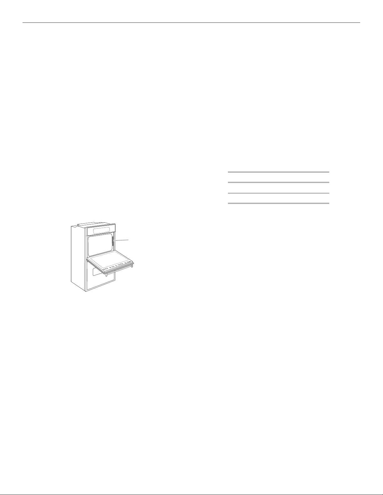
■ Oven must be connected to the proper electrical voltage,
amperage, and frequency as specied on the model/serial/
rating plate. See the following illustration.
A
A. Model/serial/rating plate
■ Models rated from 7.3 to 9.6 kW at 240 volts (5.4 to 7.4kW
at 208 volts) require a separate 40-amp circuit. Models
ratedat 4.8 kW and below at 240 volts (3.6 kW and below
at208 volts) require a separate 30-amp circuit.
■ A circuit breaker is recommended.
Voltage Rating
120/240 VAC 9.0 kW
120/208 VAC 6.8 kW
4
Page 5
INSTALLATION INSTRUCTIONS
Prepare Built-In Oven
1. Decide on the nal location for the oven. Avoid drilling
orcutting into house wiring during installation.
WARNING
Excessive Weight Hazard
Use two or more people to move and install oven.
Failure to do so can result in back or other injury.
2. To avoid oor damage, set the oven onto cardboard prior
to installation. Do not use handle or any portion of the front
frame for lifting.
3. Remove the shipping materials and tape from the oven.
Remember to keep the corner posts and other materials
thatmay be needed for installation.
4. Remove the hardware package from inside the bag
containing literature.
5. Remove and set aside racks, attachments, and other parts
from insidetheoven.
6. Move oven and cardboard close to the oven’s nal location.
Remove Oven Door(s)
IMPORTANT: Use 2 hands to remove oven door. For double
ovens, repeat the process for each door.
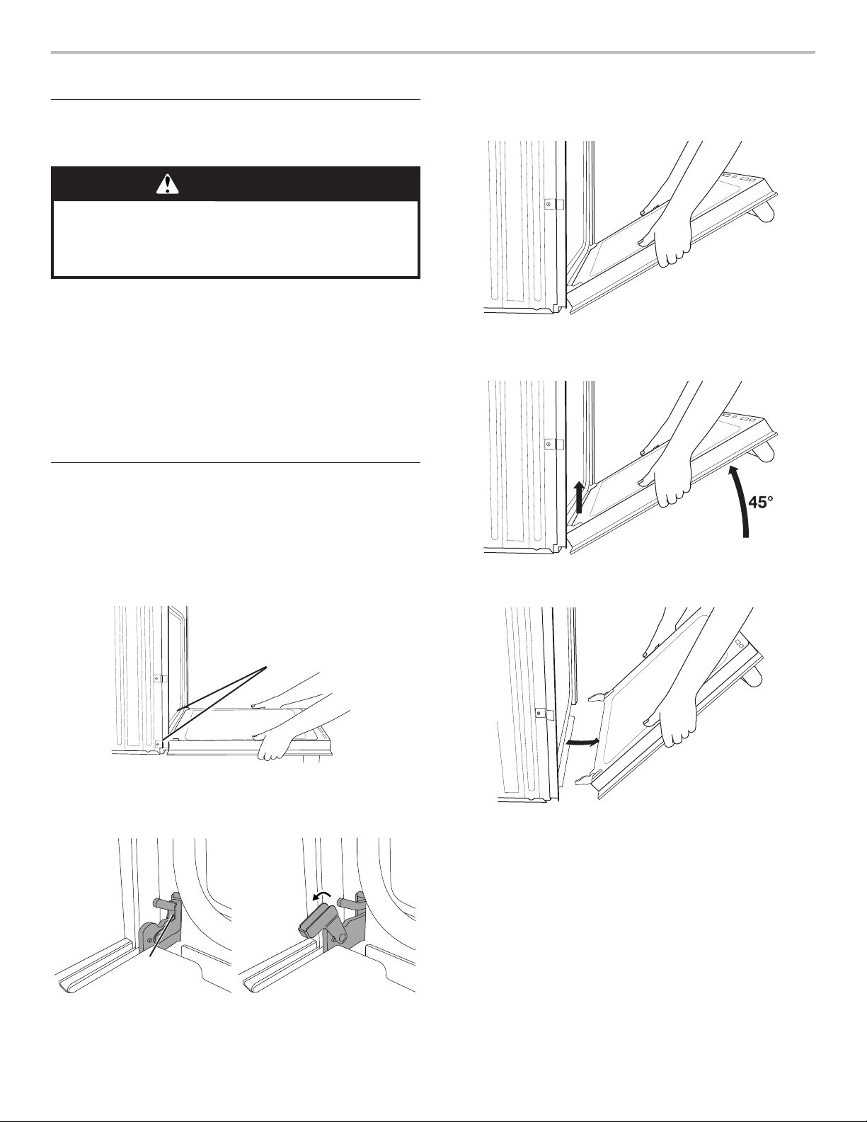
1. Prior to removing the oven door, prepare a surface where
youwill place it. This surface should be at and covered
witha soft blanket, or use the corner posts from your
packaging material.
2. Fully open the oven door.
4. Gently start to close the door. The door will stop at a partially
closed position.
5. Using 2 hands, grasp the edges of the oven door. Close the
oven door slightly past the stop position to take the weight
off of the door hinges, and then pull the oven door up.
6. Pull the oven door toward you, and then remove. You may
need to gently shift door from side to side as you pull.
Door
hinges
3. Locate the oven door hinge locks in both corners of the
ovendoor, and rotate the hinge locks toward the oven door
to the unlocked position. If the door hinge lock is not rotated
fully (see illustration B), the door will not remove properly.
Locked
position
Grip here
to rotate.
A. Oven door hinge lock in
lockedposition
Unlocked
position
B. Oven door hinge lock in
partially unlocked position
7. Set the oven door aside on the prepared covered work
surface with the oven door resting on its handle.
8. To continue with the oven installation, go to the
“PositioningOven Feet for Multiple Cabinet Cutout
Heights”section.
5
Page 6
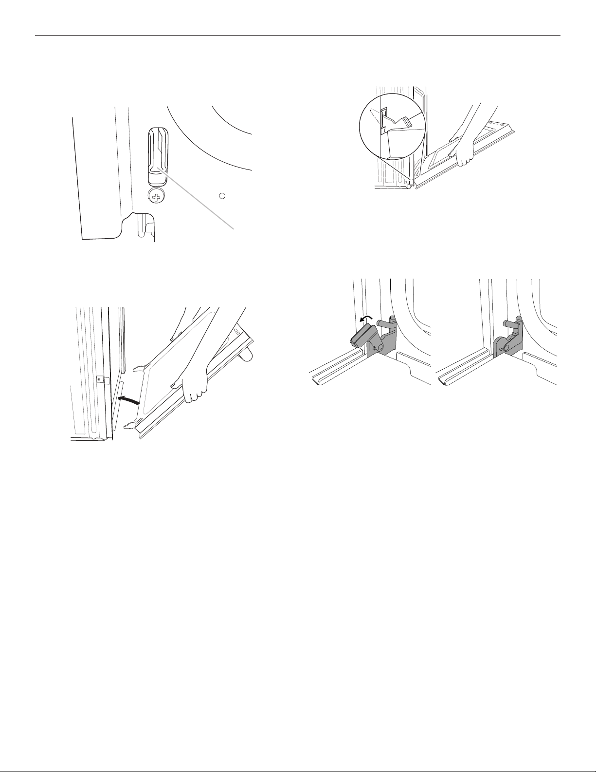
Replace Oven Door(s)
1. Using 2 hands, grasp side edges of door at the midpoint.
Face the oven cavity.
2. Locate the slots on each side of the oven front frame for
thedoor hinge locks.
A
A. Slot in the oven cavity for door hinge lock
3. Using 2 hands, grasp the edges of the oven door. At a 45°
angle, insert the hinges at the same time, and push the oven
door into the oven cavity slot to replace. You may need to
gently shift the door from side to side as you push.
4. Make sure the door hinge notch is engaged on the bottom
ofthe oven cavity slot.
IMPORTANT: Do not close the door at this step or damage
may occur to the door hinge.
5. Lower the oven door to the fully open position. If the oven
door does not open to a full 90°, repeat steps 1 through 3.
6. Locate the oven door hinge locks in the corners of the oven
door, and rotate the hinge locks toward the oven cavity to
the locked position.
Unlocked
position
Locked
position
7. After the door hinges have been locked, gently swing the
door upward to close. The door should not be forced closed.
8. When the hinges are properly installed and the door is
closed, there should be an even gap between the door and
the control panel. If one side of the oven door is lower than
the other, the hinge on that side is not properly installed.
See the “Remove Oven Door” and “Replace Oven Door”
sections.
6
Page 7
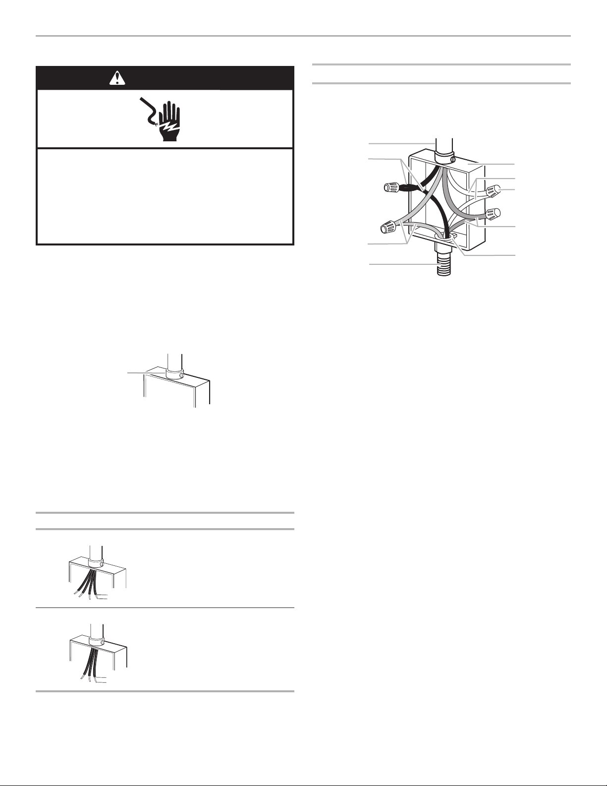
Make Electrical Connection
A
(1.3 cm)
(1.3 cm)
A
D
C
G
WARNING
Electrical Shock Hazard
Disconnect power before servicing.
Use 8 gauge copper wire.
Electrically ground oven.
Failure to follow these instructions can result in death,
fire, or electrical shock.
This oven is manufactured with a neutral (white) power
supplywire and a cabinet-connected green (or bare)
groundwiretwisted together.
1. Disconnect power.
2. Feed the exible conduit from the oven through
theopeningin the cabinet.
3. Remove junction box cover if it is present.
4. Install a UL Listed or CSA Approved conduit connector
tothejunction box.
A. UL Listed or CSA Approved conduit connector
5. Route the exible conduit from the oven to the junction box
through a UL Listed or CSA Approved conduit connector.
6. Tighten screws on conduit connector.
7. See the “Electrical Connection Options Chart” to complete
installation for your type of electrical connection.
4-Wire Cable from Home Power Supply
IMPORTANT: Use the 4-wire cable from home power
supplyinthe U.S. where local codes do not allow grounding
through neutral, New Branch circuit installations (1996 NEC),
mobile homes and recreational vehicles, new construction,
andinCanada.
B
A. Cable from home power supply
B. Black wires
C. Red wires
D. 4-wire exible conduit
fromoven
E. Junction box
F. White wires
G. UL Listed wire connectors
H. Green (or bare) ground wires
I. UL Listed or CSA Approved
conduit connector
1. Connect the 2 black wires (B) together using
aULListedwireconnector.
2. Connect the 2 red wires (C) together using
aULListedwireconnector.
3. Untwist white wire from green (or bare)
groundwirecomingfrom the oven.
4. Connect the 2 white wires (F) together using
aULListedwireconnector.
5. Connect the green (or bare) ground wire (H) from
theovencable to the green (or bare) ground wire
(inthejunction box) using a UL Listed wire connector.
6. Install junction box cover.
E
F
H
I
Electrical Connection Options Chart
If your home has: Go to section:
4-wire 4-Wire Cable from Home
½"
3-wire 3-Wire Cable from Home
½"
Power Supply
Power Supply
7
Page 8
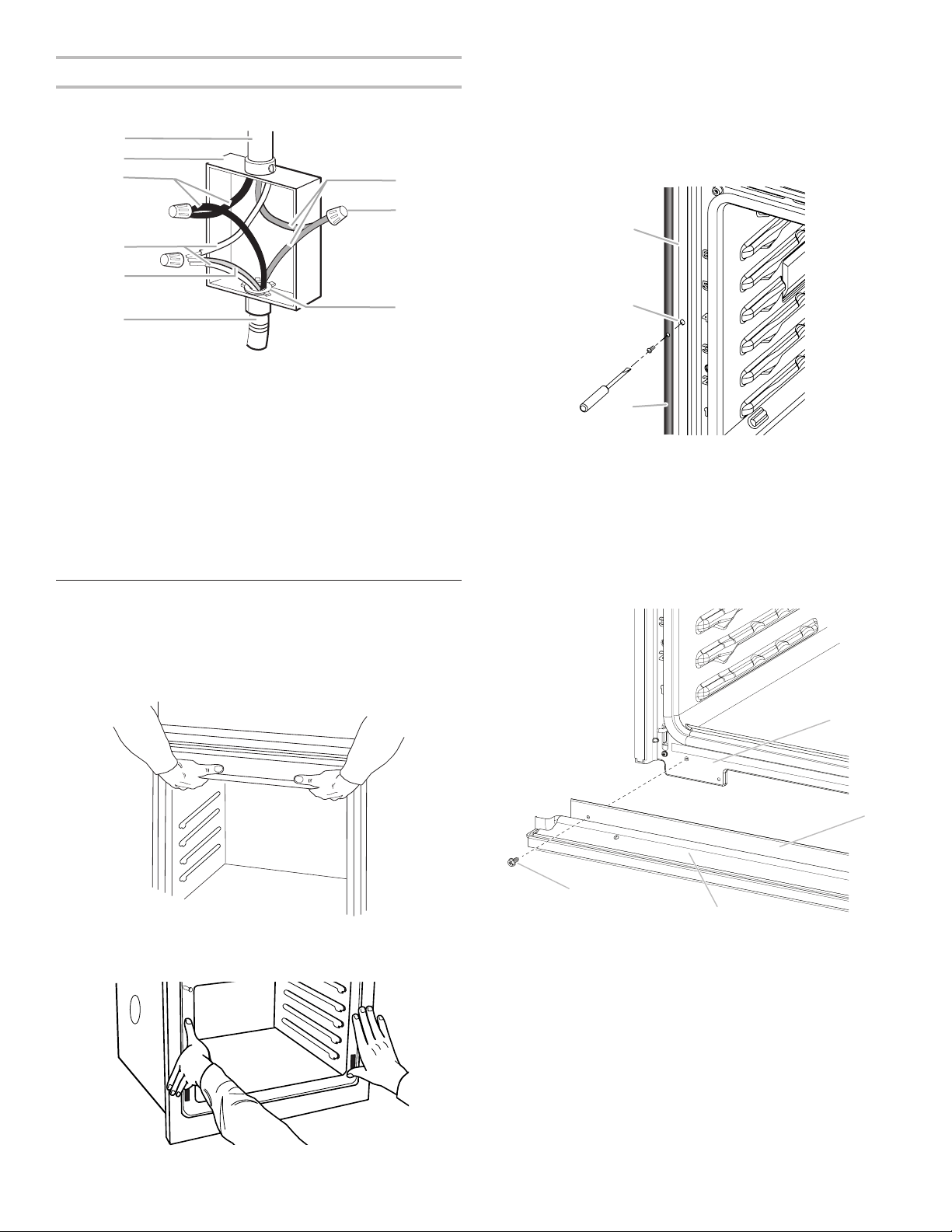
3-Wire Cable from Home Power Supply - U.S. Only
C
D
E
F
H
G
A
B
C
IMPORTANT: Use the 3-wire cable from home power
supplywhere local codes permit a 3-wire connection.
B
3. Push oven completely into the cabinet and center the oven
into the cabinet cutout.
4. Remove the tape from black front trims.
■ Securely fasten the oven to the cabinet using the #8-14 x
3
/4" (1.9 cm) screws provided.
■ Insert the screws through hole in black trim aligning with
hole in oven frame. Do not overtighten screws.
A
I
A. Cable from home power supply
B. Junction box
C. Black wires
D. White wires
E. Green (or bare) ground
wire(from oven)
F. 4-wire exible conduit
fromoven
G. Red wires
H. UL Listed wire connectors
I. UL Listed or CSA Approved
conduit connector
1. Connect the 2 black wires (C) together using
aULListedwireconnector.
2. Connect the 2 white wires (D) and the green (or bare) ground
wire (of the oven cable) using a UL Listed wire connector.
3. Connect the 2 red wires (G) together using
aULListedwireconnector.
4. Install junction box cover.
Install Oven
1. Using 2 or more people, lift the oven partially into the cabinet
cutout. Use the oven opening as an area to grip.
NOTE: Push against seal area of the oven front frame when
pushing the oven into the cabinet. Do not push against the
outside edges.
B
C
A. Oven frame
B. Oven frame hole
C. Black trim piece
5. The bottom vent is shipped in the foam packing at the top of
the oven. Install the bottom vent (C) as follows:
■ Align vent tab (B) with oven frame (A) as shown.
■ Using one #8-18 x
3
/8" (9.5 mm) screw (D) on each side of
the venttab (B), fasten the vent securely to the oven.
A
D
2. Push against the seal area of the front frame to push
theoven into the cabinet until the back surface of the
frontframe touches the front wall of the cabinet.
A. Oven frame
B. Vent tab
C. Oven vent
D. #8-18 x 3/8" (9.5 mm) screws
6. Replace oven racks.
7. Replace the oven door. See the “Replace Oven Door(s)”
section.
8. Check that door is free to open and close. If it is not, repeat
8
the removal and installation procedures. See the “Prepare
Built-In Microwave/Oven Combination” section.
9. Reconnect power.
10. The display panel will light briey, and “PF” should appear in
the display.
11. If the display panel does not light, please reference the
“Warranty” section of the Use and Care Guide.
Page 9

Complete Installation
1. Check that all parts are now installed. If there is an extra part,
go back through the steps to see which step was skipped.
2. Check that you have all of your tools.
3. Dispose of/recycle all packaging materials.
4. For oven use and cleaning, read the Use and Care Guide.
Check Operation of Lower Oven
1. Turn on power.
2. At rst use, set up the clock and any other preferences,
if available. For more information, read the Use and Care
Guide.
3. Start a broil cycle. See the User Instructions for instructions.
NOTE: Odors and smoke are normal when the oven is used
the rst few times.
4. Wait 5 minutes, then check for heat.
If Oven Does Not Operate, Check the Following:
■ Household fuse is intact and tight; or circuit breaker has
not tripped.
■ Electrical supply is connected.
■ See the “Troubleshooting” section in the User
Instructions.
5. Place the SatinGlide™ Roll-Out Extension Rack for Smart
Oven+ Attachments in the lowest rack position in the unit to
make sure the correct accessory rack is on the bottom.
6. Press CANCEL OVEN.
Check Operation of Microwave Oven
1. Fill a microwave-safe container with 1 cup (250 mL) of water
and place container inside microwave oven. Close door
rmly.
2. Start a microwave cook cycle for 2 minutes. The interior
microwave oven light should be on, and the remaining
cooking time should be displayed.
When display reads “1:00” minute, open microwave oven
door. The microwave should stop cooking. Close door rmly.
The interior microwave oven light should turn off.
3. Press START. Microwave oven should begin cooking, and
the microwave oven interior light should be on.
Let microwave oven complete cooking time. A tone will
sound at the end of the cooking time, and the microwave
oven will shut off.
4. Open microwave oven door and slowly remove container.
Water in container should be hot.
If You Need Assistance or Service:
Please reference the “Warranty” section of the Use
andCareGuide.
9
Page 10

W11047062B
©2018. All rights reserved. Used under license in Canada
Tous droits réservés. Utilisé sous licence au Canada. 04/18
 Loading...