


KAC-47
TECHNICAL EDUCATION
TOUCH-ACTIVATED
ELECTRONIC
INDUCTION COOKTOP
MODELS: KICU508SBL & KICU568SBL
JOB AID 4317409
FORWARD
This KitchenAid Job Aid “Touch-Activated Electronic Induction Cooktop” (Part No. 4317409), provides the In-Home Service Professional with information on the installation, operation, and service of the Touch-Activated Electronic Induction Cooktop. For specific information on the model being serviced, refer to the “Use and Care Guide,” or “Wiring Diagram” provided with the cooktop.
The Wiring Diagrams used in this Job Aid are typical and should be used for training purposes only. Always use the Wiring Diagram supplied with the product when servicing the cooktop.
GOALS AND OBJECTIVES
The goal of this Job Aid is to provide information that will enable the In-Home Service Professional to properly diagnose malfunctions and repair the Touch-Activated Electronic Induction Cooktop.
The objectives of this Job Aid are to:
•Understand and follow proper safety precautions.
•Successfully troubleshoot and diagnose malfunctions.
•Successfully perform necessary repairs.
•Successfully return the cooktop to its proper operational status.
WHIRLPOOL CORPORATION assumes no responsibility for any repairs made on our products by anyone other than authorized In-Home Service Professionals.
Copyright © 2007, Whirlpool Corporation, Benton Harbor, MI 49022
- ii -
TABLE OF CONTENTS
|
Page |
GENERAL .............................................................................................................................. |
1-1 |
Cooktop Safety .................................................................................................................. |
1-1 |
Model & Serial Number Designations................................................................................ |
1-2 |
Model & Serial Number Label And Wiring Diagram Locations........................................... |
1-3 |
Specifications..................................................................................................................... |
1-4 |
INSTALLATION INFORMATION ............................................................................................ |
2-1 |
Installation Instructions ...................................................................................................... |
2-1 |
PRODUCT OPERATION ....................................................................................................... |
3-1 |
Theory Of Operation .......................................................................................................... |
3-1 |
Troubleshooting ................................................................................................................. |
3-4 |
COMPONENT ACCESS ........................................................................................................ |
4-1 |
Component Locations........................................................................................................ |
4-1 |
Removing The Cooktop Glass ........................................................................................... |
4-2 |
Removing The Touch Control Board.................................................................................. |
4-3 |
Removing An Induction Element Assembly ....................................................................... |
4-4 |
Removing A Negative Temperature Coefficient (NTC) Sensor .......................................... |
4-6 |
Removing A Cooling Fan And An Electronic Board............................................................ |
4-7 |
Removing A 20A Line Fuse................................................................................................ |
4-8 |
COMPONENT TESTING ........................................................................................................ |
5-1 |
Induction Elements ............................................................................................................ |
5-1 |
Negative Temperature Coefficient (NTC) Sensor............................................................... |
5-2 |
Electronic Board IC Check................................................................................................. |
5-3 |
20A Line Fuses .................................................................................................................. |
5-3 |
DIAGNOSTICS & TROUBLESHOOTING ............................................................................. |
6-1 |
Electronic Board Error Codes ............................................................................................ |
6-1 |
Touch Control Board Error Codes...................................................................................... |
6-2 |
WIRING DIAGRAMS ............................................................................................................. |
7-1 |
30˝ Cooktop ...................................................................................................................... |
7-1 |
36˝ Cooktop ...................................................................................................................... |
7-2 |
- iii -
— NOTES —
- iv -

GENERAL
COOKTOP SAFETY
Your safety and the safety of others are very important.
We have provided many important safety messages in this manual and on the appliance. Always read and obey all safety messages.
This is the safety alert symbol.
This symbol alerts you to potential hazards that can kill or hurt you and others.
All safety messages will follow the safety alert symbol and either the word “DANGER” or “WARNING.” These words mean:
 DANGER
 WARNING
You can be killed or seriously injured if you don’t immediately follow instructions.
You can be killed or seriously injured if you don’t follow instructions.
All safety messages will tell you what the potential hazard is, tell you how to reduce the chance of injury, and tell you what can happen if the instructions are not followed.
1-1

MODEL & SERIAL NUMBER DESIGNATIONS
MODEL NUMBER |
|
K |
|
IC |
|
U |
|
50 8 S BL 0 |
|
|
|
|
|||||
|
|
|
|
|
|
|
|
|
PRODUCT GROUP |
|
|
|
|
|
|
|
|
K = KITCHENAID |
|
|
|
|
|
|
|
|
|
|
|
|
|
|
|
|
|
PRODUCT IDENTIFICATION |
|
|
|
|
|
|
|
|
EC = ELECTRIC COOKTOP |
|
|
|
|
|
|
|
|
GC = GAS COOKTOP |
|
|
|
|
|
|
|
|
IC = INDUCTION COOKTOP |
|
|
|
|
|
|
|
|
MERCHANDISING SCHEME |
|
|
|
|
|
|
|
|
C = CERAMIC GLASS |
|
|
|
|
|
|
|
|
S = STANDARD / PORCELAIN METAL |
|
|
|
|
|
|
|
|
T = TEMPERED GLASS |
|
|
|
|
|
|
|
|
U = ULTIMA |
|
|
|
|
|
|
|
|
V = VBL PRO LINE SERIES |
|
|
|
|
|
|
|
|
X = 208 VOLTS |
|
|
|
|
|
|
|
|
CAPACITY / SIZE / SERIES / CONFIGURATION
1ST POSITION |
2ND POSITION |
||
0 |
= 2 BURN. / ELEM. |
0 |
= 30˝ WIDE |
1 |
= STANDARD |
2 |
= 42˝ OR 12˝ WIDE |
2 |
= GRILL / GRIDDLE |
3 |
= 33˝ WIDE |
3 |
= TEMP. GLASS |
5 |
= 15˝ WIDE |
4 |
= COMMERCIAL |
6 |
= 36˝ WIDE |
5 |
= CERAMIC GLASS |
8 |
= 48˝ WIDE |
FEATURE CODE
0 = STANDARD ELEMENTS / BURNERS
1 = RADIANT ELEMENTS
2 = DUAL ELEMENTS OR SEALED BURNERS W/GRILL
6 = 5 BURNERS / ELEMENTS
7 = HALOGEN ELEMENTS / OR 6 BURNERS
8 = TOUCH CONTROLS
9 = INDUCTION
YEAR OF INTRODUCTION
S = 2006
COLOR CODE
BL = BLACK
ENGINEERING CHANGE (0, 1, 2, ETC.)
SERIAL NUMBER |
|
XT |
|
U |
|
24 |
|
01234 |
|
|
|
|
|||||
|
|
|
|
|
|
|
|
|
DIVISION RESPONSIBILITY |
|
|
|
|
|
|
|
|
XT = OXFORD |
|
|
|
|
|
|
|
|
YEAR OF PRODUCTION |
|
|
|
|
|
|
|
|
U = 2007 |
|
|
|
|
|
|
|
|
WEEK OF PRODUCTION |
|
|
|
|
|
|
|
|
24 = 24TH WEEK |
|
|
|
|
|
|
|
|
PRODUCT SEQUENCE NUMBER
1-2

MODEL & SERIAL NUMBER LABEL
AND WIRING DIAGRAM LOCATIONS
The Model/Serial Number label and Wiring Diagram locations are shown below.
Wiring Diagram Location |
Model & Serial Number |
(On Bottom Of Cooktop) |
Label Location |
1-3

SPECIFICATIONS
|
|
|
Model Number |
KICU508SBL |
KICU568SBL |
Model Description |
Touch Activated 30˝ Ceramic |
Touch Activated 36˝ Ceramic |
|
Premium Black Induction Cooktop |
Premium Black Induction Cooktop |
|
30˝ |
36˝ |
Size-Configuration |
|
|
Dimensions/Specifications |
|
|
Exterior Dimensions |
|
|
Overall Height (in) |
3-1/4˝ |
3-1/4˝ |
|
31˝ |
37˝ |
Overall Width (in) |
|
|
Overall Depth (in) |
21-9/16˝ |
21-9/16˝ |
|
||
Cutout Dimensions |
3˝ |
3˝ |
|
||
Burner Box Height |
|
|
Cutout Width (in) |
29-1/2˝ |
35-1/2˝ |
|
||
Cutout Depth (in) |
20-1/2˝ |
20-1/2˝ |
|
||
Weight |
|
|
Net Weight (lbs) |
44.1 |
50.7 |
Ratings |
|
|
Electric Voltage/Phase/Frequency (Hz) |
240/208 Volt,Single Phase,60Hz |
240/208 Volt,Single Phase,60Hz |
Total Connected Load In kW |
|
|
240 Volts (Preferred) |
7.2 |
10.6 |
208 Volts |
6.65 |
10.3 |
Circuit Amps |
30 Amp (240V) / 32 Amp (208V) |
45 Amp (240V) / 48 Amp (208V) |
Exterior |
|
|
Cooktop Finish |
Ceramic Glass |
Ceramic Glass |
Cooktop Color |
Premium Black |
Premium Black |
Cooktop Controls |
Touch Activated |
Touch Activated |
Cooktop Control Type |
LED |
LED |
Cooktop Control # |
4 |
5 |
Electronic Control |
Yes - Touch Activated LED Control |
Yes - Touch Activated LED Control |
Keep Warm |
Yes (“h”) |
Yes (“h”) |
Keep Warm Switch |
Yes (Press + and - at the same time) |
Yes (Press + and - at the same time) |
Cooktop Features |
|
|
Power On Light |
4 |
5 |
Autofocus Light |
No |
Yes |
Hot Surface Indicator |
4 (“H”) |
5 (“H”) |
Kitchen Timer |
Yes (99 Min.) |
Yes (99 Min.) |
Control Lock |
Yes |
Yes |
Ele R Front Size & Type |
5-7/8˝ Single Induction |
8-1/4˝ Single Induction |
Ele RF Output (W@240/208V) |
1400W/1320W |
2200W/2075W |
Ele L Front Size & Type |
7-1/8˝ Single Induction |
7-1/8˝ Single Induction |
Ele LF Output (W@240/208V) |
1800W/1700W |
1800W/1700W |
Ele R Rear Size & Type |
11˝ Single Induction |
5-7/8˝ Single Induction |
Ele RR Output (W@240/208V) |
2400W/2200W |
1400W/1320W |
Ele L Rear Size & Type |
7-1/8˝ Single Induction |
7-1/8˝ Single Induction |
Ele LR Output (W@240/208V) |
1800W/1700W |
1800W/1700W |
Ele C Front Size & Type |
|
11˝/ 7-1/8˝ Dual Zone Induction |
Ele CF Output (W@240/208V) |
|
3600W - 1800W/3120 - 1700W |
1-4

Model Number |
KICU508SBL |
KICU568SBL |
Miscellaneous |
|
|
Product Literature |
|
|
Installation Instructions |
Yes |
Yes |
Parts List |
Yes |
Yes |
Service Manual/Job Aid |
Yes |
Yes |
Tech Sheet |
Yes |
Yes |
Use & Care Guide |
Yes |
Yes |
Other |
|
|
Agency Approvals |
UL, CUL |
UL, CUL |
Approved to Install Over BI Oven |
Yes |
Yes |
Hardware |
Yes |
Yes |
Power Cord Length & # Wires |
3 Foot/3 Wire |
3 Foot/3 Wire |
Residential Use Only |
Yes |
Yes |
Warranty |
|
|
Limited |
12 Mo |
12 Mo |
Extended |
|
|
Ceramic Glass Cooking Surface |
60 Mo. Parts only |
60 Mo. Parts Only |
Electronic Controls |
60 Mo. Parts only |
60 Mo. Parts Only |
Electrical Elements |
60 Mo. Parts only |
60 Mo. Parts Only |
1-5
— NOTES —
1-6
INSTALLATION INFORMATION
INSTALLATION INSTRUCTIONS
INSTALL HEAT SHIELD
1.Decide on the final location for the cooktop.
 WARNING
Excessive Weight Hazard
Use two or more people to move and install cooktop.
Failure to do so can result in back or other injury.
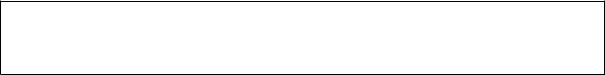
2.Using two or more people, place the cooktop upside down on a covered work surface.
3.Remove the heat shield from the cooktop. Set the two screws aside for reattaching the heat shield.
B
A
A.Heat shield
B.Remove screws
4.Using two screws, reattach the heat shield to the underside of the cooktop at the predrilled holes as shown in the following illustration.
B
A
A.Heat shield
B.Predrilled holes
INSTALL COOKTOP
Style 1: Cooktop over undercounter built-in oven
IMPORTANT:
•Your cooktop may not be approved for use over an undercounter built-in oven. Contact your dealer to confirm that your cooktop is approved.
•Clamping brackets should not be used.
1.Turn cooktop right side up.
2.Place cooktop in cutout.
NOTE: Make sure that the front edge of the cooktop is parallel to the front edge of the countertop. If repositioning is needed, lift entire cooktop up from cutout to avoid scratching the countertop.
2-1
Style 2: Cooktop over cabinets
1.Determine whether your cabinet constructionprovidesclearanceforinstallingclamping brackets at cooktop base ends. This is the recommended location. Clamping brackets can be installed on the back of cooktop base bottom, if necessary.
A
B
A.Attachment screw holes, side or back locations
B.Front of cooktop
2.The clamping brackets can be installed before or after the cooktop is placed into the cutout. Complete the following steps for the option you choose.
Installing Brackets Before Placing
Cooktop in Cutout
1.Positionbrackettoallowtheclampingbracket
toextendfarenoughoutfromthecooktopfor the installation of 2-1/2˝ (6.4 cm) clamping screws.See“AttachCooktoptoCountertop” for illustration of clamping screw installation.
A
B
C
A.Clamping bracket
B.Attachment screw and washer
C.Clamping screw
2.Rotate brackets so they do not extend beyond edge of cooktop base.
3.Tighten screws enough to hold brackets in place when cooktop is placed into the cutout.
4.Turn the cooktop right side up and place in cutout.
NOTE: Make sure that the front edge of the cooktop is parallel to the front edge of the countertop. If repositioning is needed, lift entire cooktop up from cutout to avoid scratching the countertop.
5.Loosenthescrewsandrotatethebrackets so that they are perpendicular to the edge of the cooktop base and extend beyond its edge. Securely tighten screws.
Installing Brackets After Placing
Cooktop in Cutout
1.Place cooktop in cutout.
NOTE: Make sure that the front edge of the cooktop is parallel to the front edge of the countertop. If repositioning is needed, lift entire cooktop up from cutout to avoid scratching the countertop.
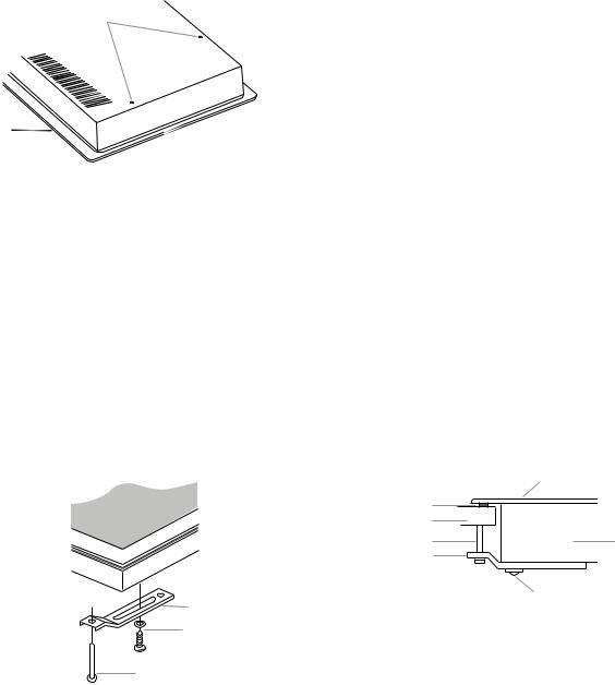
2.Position clamping bracket to allow the
bracket to extend far enough out from the cooktopfortheinstallationof2-1/2˝(6.4cm) clamping screws
G
F
E
D
A.Glass cooktop
B.Cooktop base
C.Attachment screw
D.Clamping bracket
(extends far enough beyond cooktop base to allow installation of clamping screws)
A
B
C
E.2-1/2" (6.4 cm) clamping screw (to be installed in “Attach Cooktop to Countertop” section)
F.Countertop G. Foam seal
3.Attach brackets to cooktop base bottom with bracket attachment screws using the bracket mounting holes. Securely tighten screws.
2-2
 Loading...