

Page 1
Before using this Compact Static Eliminator, be sure to
thoroughly read this Instruction Manual.
After you are finished with this Instruction Manual, be
sure to store it in a safe place for quick reference.
High-performance Micro Static Eliminator
Instruction Manual
SJ-M
96M10104
Page 2
Preface
This document describes handling, method of operation and precautions when using the Compact
Spot-type Static Eliminator SJ-M 100/200 Series. Before you start to use the SJ-M 100/200 Series, be
sure to thoroughly read this document in order to make full use and safely use its functions.
Store this document in a safe place so that you can retrieve it whenever necessary.
■ Symbols
This manual uses the following symbols to alert you to important information.
Be sure to read this information.
Failure to follow these instructions may lead to death or serious injury.
Failure to follow these instructions may lead to injury.
Failure to follow these instructions may lead to product damage (product
malfunction, etc.).
Provides additional information on precautions and restrictions that must be
followed in operation.
Provides additional information on proper operation.
Indicates useful information or information that aids understanding of text descriptions.
Indicates a reference item or page to be referred to in this manual or a separate manual.
DANGER
WARNING
CAUTION
Important
Note
Tip
Safety Precautions
■ General Precautions
• At startup and during operation, be sure to monitor the functions and
performance of the SJ-M Series.
• We recommend that you take substantial safety measures to avoid any
damage in the event that a problem occurs.
• Do not modify the SJ-M Series or use it in any way other than described in
the specifications. The functions and performance of products used or
modified in this way cannot be assured.
• When the SJ-M Series is used in combination with other instruments,
functions and performance may be degraded, depending on operating
conditions and the surrounding environment. Use the SJ-M after fully
studying the effect of combined use with other instruments.
• Do not use the SJ-M Series for the purpose of protecting the human body.
■ SJ-M Series Handling Precautions
The SJ-M Series is a high-voltage product that is not designed in an explosion-proof structure. Pay
attention to the following when using the SJ-M Series.
•
To prevent electric shock and to ensure accurate static elimination, be sure
to connect a Class D earth (maximum resistance of 100 Ohms).
•
The power cable supplied with the exclusive power supply (SJ-U2) is a 125 V
rated power cable. When connecting a power supply that exceeds this power
rating to the SJ-M Series, the user must prepare a power cable having
adequate voltage rating. If a power cable that does not meet the voltage
rating is used, this may cause electric shock, fire or malfunction.
•
Do not use this product in locations where there is the risk of ignition or
explosion from flammable solvents or dirt and dust.
•
High voltage is applied to this product. Prevent it from being splashed with
water, oil, or flammable solvents. Failure to do so may cause insulation
breakdown, which will result in electric shock or malfunction.
•
Do not bring your fingers, tools, wire or other metallic objects near this
product. Doing so may cause electric shock or malfunction.
•
Protect the area around the tip of the Static Elimination Head with silicon,
fluoro-resin or other highly ozone-resistant resin. Ozone that is generated
may cause the metal or resin on the SJ-M Series to rust, corrode or
deteriorate.
The ozone generated from this product may adversely affect the human
body. For this reason, do not use the SJ-M Series in closed spaces. Be sure
to use the SJ-M Series in a well-ventilated location. Also, do not bring your
face close to the Static Elimination Head. The ozone generated from this
product might be painful to your nose or throat.
•
Do not use this product in locations where sudden changes in temperature
or condensation are likely to occur.
•
Do not operate this product with wet hands. Doing so may cause electric
shock.
•
Before starting inspection or maintenance, be sure to turn the power OFF.
Failure to do so might result in electric shock or malfunction.
•
During maintenance, do not directly touch the electrode probe. Doing so may
cause personal injury.
•
Supply air according to the deratings indicated in the specifications. Use
without performing derating might result in electric shock or malfunction
•
If any malfunction is observed in this product, immediately turn it OFF, and
contact your nearest agent. You should never repair this product yourself.
Doing so may cause electric shock or malfunction.
CAUTION
WARNING
• Do not touch the electrode probe with a tool or other hard object. Damage to
the electrode probe will prevent static elimination performance from being
fully demonstrated, and cause accidents or malfunction.
• When this product is used for a long period of time, the electrode probe
become dirty due to the adhesion of dust and dirt. If the ion level alarm
indicator or condition alarm indicator lights, clean the electrode probe. If the
product is used with the electrode probe in a dirty or dusty state, the static
elimination performance can no longer be fully demonstrated, resulting in
accidents or malfunction. We recommend periodically cleaning the
electrode probe (as a guideline, once every two weeks in a regular operating
environment though this depends on the installation conditions).
• Do not drop or subject this product to shock. Doing so might result in
accident or malfunction.
• Use this product for static elimination only. Do not use it for other purposes.
• When installing the SJ-M Series, observe the minimum bending radius of all
provided cables. Also, do not install the SJ-M with the cables deformed by
staples or other objects. Doing so might cause the SJ-M to malfunction.
■ Power Supply Precautions
• Use a DC power supply with rated 24 V output.
• Noise applied to the power supply may cause this product to malfunction. If
this happens, install an insulated transformer.
• When using a switching regulator, be sure to connect a Class D earth to the
Frame Ground terminal.
■ Grounding Precautions
• To ensure safety and appropriate static elimination, be sure to ground this
product.
• Be sure to connect a Class D earth (maximum resistance of 100 Ohms)
■ Air Purge Function Precautions
• Be sure to use air of pressure 0.001 MPa to 0.5 MPa. Use outside of the rated
air pressure range might result in accidents or malfunction.
• Be sure to supply clean or dry air of temperature –20°C or more through a
filter of mesh size about 0.01μm. Moisture or oil contained in the air or
nitrogen may cause discharge inside the Static Elimination Head, which
may result in accidents or malfunction.
CAUTION
CAUTION
CAUTION
CAUTION
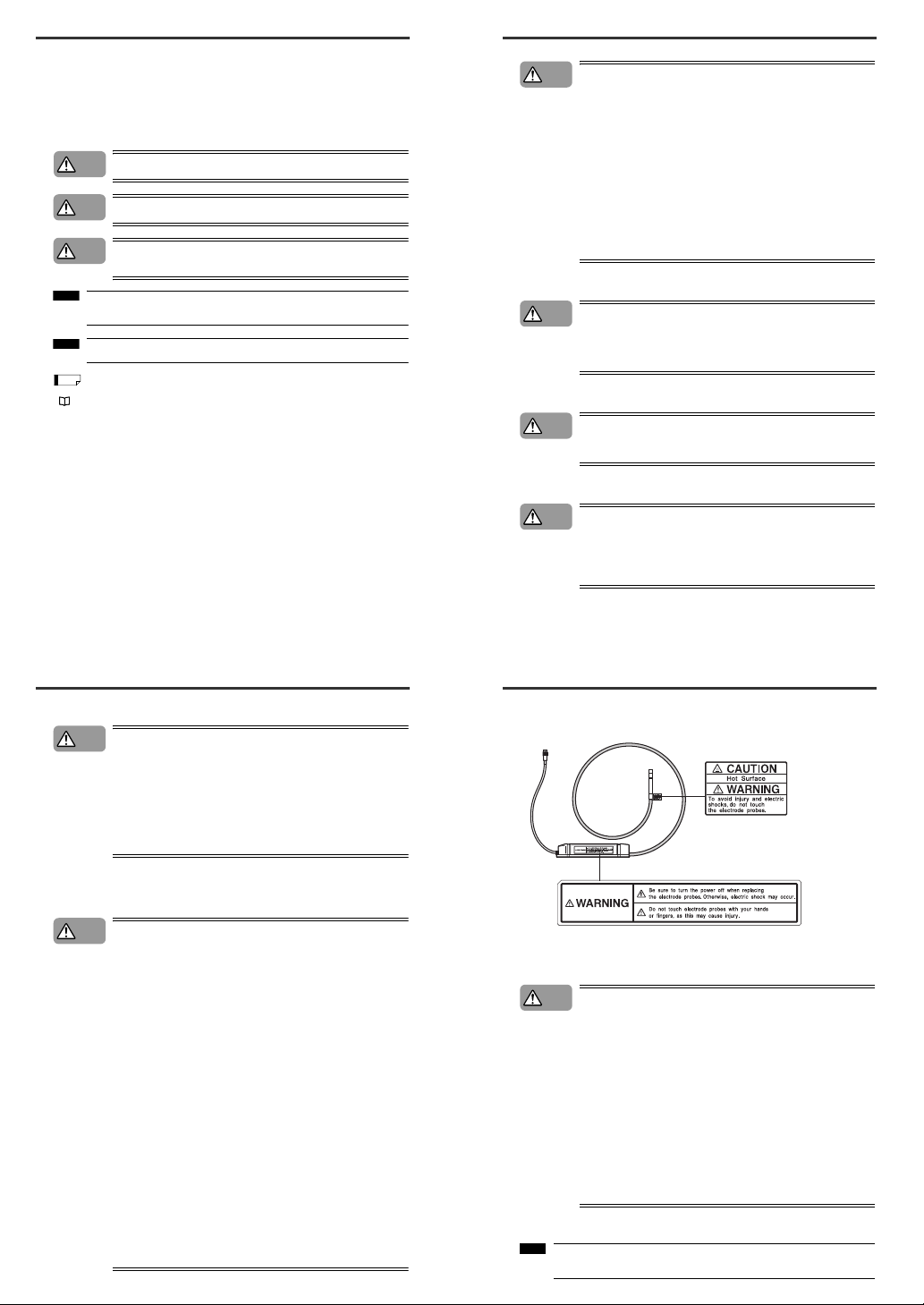
■ SJ-M Series Warning label
A WARNING label is affixed on the SJ-M Series to ensure safety. Read the description on this
WARNING label to ensure correct use of the SJ-M Series.
■ Installation Precautions
Avoid installing the SJ-M Series in the following locations as this may cause
accidents.
• Locations directly subject to vibration and shock
• Locations subject to ambient temperature outside of the 0°C to +40°C range
(excluding the High-voltage Cable Unit)
• Locations subject to ambient temperature outside of the 0°C to +80°C range
(High-voltage Cable Unit)
• Locations subject to ambient humidity outside of the 35 to 65%RH range
(condensation not allowed) (excluding the High-voltage Cable Unit)
• Locations subject to ambient humidity outside of the derating range
(condensation not allowed) indicated in the specifications (High-voltage
Cable Unit)
• Locations subject to sudden changes in temperature
• Locations subject directly to blasts from air conditioners
• Locations subject to volatile or flammable substance, solvents or corrosive
gases
• Locations subject to large amounts of dirt, and dust, salt, iron and oil smoke
• Locations that may be splashed with water, oil or chemical mist
• Locations where strong magnetic and electrical fields are generated
■ About Warm-up
After turning the SJ-M Series ON, leave it for about 20 minutes to allow the ion
balance to stabilize.
WARNING labels in Japanese, German, French, Italian and Chinese (Simplified) are provided.
Use them as necessary.
CAUTION
Note
1
Page 3
■ Other Precautions
•
Be sure to read the WARNINGS and CAUTIONS described in each of the
items in this Instruction Manual.
•
This Static Eliminator has a built-in EEPROM. Do not turn the Static
Eliminator OFF during the setup.
Install the tip of the SJ-M010/020(G) paying attention to the following point.
●Install the Static Elimination Head away from the wall or surrounding
objects.
●Protect the area around the tip of the Static Elimination Head with silicon,
fluoro-resin or other highly ozone-resistant resin. Ozone that is generated
may cause the metal or resin on the SJ-M010/020(G) to rust, corrode or
deteriorate.
• Do not install the Static Elimination Head at locations where moving parts of
other equipment and machinery may place stress on the cable. Doing so
might cause the SJ-M010/020(G) to malfunction.
CAUTION
CAUTION
The section marked by "*" must not touch the conductor (earthed body).
The adapter nozzle must not touch the conductor (earthed body).
23mm*
10 mm or more
10 mm
or more
10 mm or more
10 mm
or more
Requires 10 mm or more away
from the air outlet
*
• SJ-M010/020 (G)
200 mm
or more
20 mm
or more
10 mm
or more
20 mm
or more
20 mm or more
10 mm
or more
200 mm or more
10 mm
or more
20 mm or more
20 mm or more
200 mm or more
When SJ-MS2
is used
When SJ-ML1
is used
When SJ-MS1
is used
200 mm
or more
20 mm
or more
10 mm
or more
20 mm
or more
• SJ-M010/020 (G)
200 mm
or more
20 mm
or more
10 mm
or more
20 mm
or more
200 mm
or more
20 mm
or more
10 mm
or more
20 mm
or more
When SJ-MS3 is used When SJ-ML2 is used
Precautions on Regulations and Standards
■ CE Marking
Keyence Corporation has confirmed that this product complies with the essential requirements of the
applicable EC Directive, based on the following specifications.
Be sure to consider the following specifications when using this product in the Member State of
European Union.
● EMC Directive(2004/108/EC)
• Applicable standard EMI: 61326-1(evaluated according to EN55011 Group 1, Class A)
EMS: 61326-1
•Be sure to provide a ground when installing the SJ-M.
• The length of cable (power lead and I/O leads) must be less than or equal to 30 m.
• Attach a one-loop ferrite core onto the High-voltage Cable Unit and pass the connector cable once
through the core.
• The following ferrite core is recommended:
SFC-10 made by KITAGAWA INDUSTRIES CO,LTD.
Remarks:
These specifications do not give any guarantee that the end-product with this product incorporated
complies with the essential requirements of EMC Directive. The manufacturer of the end-product is
solely responsible for the compliance on the end-product itself according to EMC Directive.
● Low-Voltage Directive (2006/95/EC)
• Applicable Standard: EN61010-1
• Overvoltage category I
• Use this product under pollution degree 2.
•Use the power supply for the SJ-M Series, that satisfies the requirements of the Limited Power
Source specifications stipulated in EN60950-1 and certified by European third-party certification
organization, or a Keyence Corporation AC adapter (SJ-U2). The specifications of the AC adapter
(SJ-U2) are as follows.
When connecting to an SJ-U2, be sure to use a power cable compliant with European standards.
Applicable standard: EN60950-1
Overvoltage category II
Poll ution degree 2
•Be sure to provide a ground when installing the SJ-M Series.
1-1 Features of the SJ-M Series
This section describes an outline of the functions, the features of the SJ-M Series.
Outline of the SJ-M Series
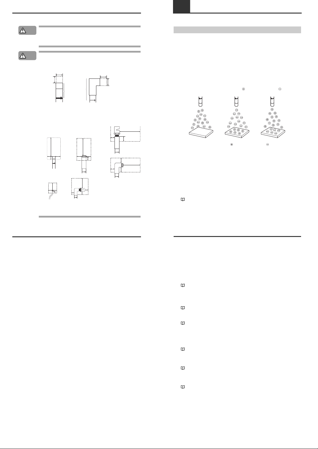
■ Pulse AC method
The SJ-M Series uses a pulse AC method that generates + and – charged air ions from a single
electrode probe. This system ensures a maximum ion level per unit time, which in turn high-speed static
elimination. The SJ-M Series also automatically controls the level of + and – ions generated matched to
the charged state of the target object. This enables high-speed and high-precision static elimination
suited to installation conditions.
■ I.C.C. (Ion Current Control) method
This control method calculates the charged level of the target object by sensing the state of ion current
that arises due to the potential difference between the electrode on the Static Elimination Head and
GND. Optimum static elimination matched to the state of the target object can be performed by rapidly
supplying the optimum ions suited to the polarity and charged level of the target object.
■ Ion monitor functions
●
Charge monitor
The integrated ion monitor allows you to learn how much the target object is charged by + or – ions.
This monitor also allows you to confirm at a glance how static elimination is being performed.
● Ion level monitor
The ion level currently being generated by the Static Elimination Head is monitored at all times so that
drops in the generated ion level can be diagnosed on the unit. The generated ion level is indicated by
LEDs and an alarm can be output when the generated ions fall below a certain level. This allows you to
monitor the influence of a dirty electrode probe in advance.
"Ion Monitor Functions" (page 8)
Regular state
Tar get object in
non-charged state
Elimination of ions
from target object
Elimination of ions
from target object
Tar get object
charged
Tar get object
charged
1-1
Features of the SJ-M Series
■ Alarm output functions
●
Alarm output functions
An indicator blinks and an alarm signal is output, for example, when internal circuits are damaged or
abnormal discharging occurs. When an alarm signal is output, generation of ions is forcibly stopped.
●
Ion level alarm output function
An indicator lights and an alarm signal is output when the level of generated ions drops due to a dirty
electrode probe, for example.
●
Condition alarm output function
An indicator lights and an alarm signal is output when static elimination performance is impaired.
"Alarm Output Functions" (page 9)
■ Abnormal discharge detection function
Abnormal discharge caused by condensation on the electrode probe tip or adhesion of debris is
detected. When abnormal discharge is detected, ion generation is forcibly stopped to prevent trouble at
an early stage.
"Abnormal Discharge Detection Function" (page 9)
■ Ion balance adjustment function
The ion balance zero point can be fine-adjusted.
"Ion Balance Adjustment Function" (page 8)
■ Static elimination stop function
Static elimination only can be turned ON/OFF with the device still powered. This is achieved by shorting
the 0V terminal with the static elimination stop input terminal on the Controller Unit (I/O terminal
section) or by holding down the two ion balance adjustment keys simultaneously for about three
seconds.
"Static Elimination Stop Function" (page 9)
■ Air purge function
Dirt can be prevented from sticking to the electrode probe on the SJ-M010/020 (G) by attaching a tube
to the air duct and supplying clean or dry air. This also extends the static elimination range.
"Air Purge Function" (page 9)
■ High-temperature static elimination
The High Temperature mode allows static to be eliminated in hot environments.
(ambient operating temperature: SJ-M010/020 (G), 0 to +80°C)
"High temperature use setting" (page 7)
2
Page 4
1-2
Checking the Contents of the Package
The package contains the following components and accessories. Before you start using the SJ-M
Series, make sure that the package contains everything that it is supposed to contain. A Replacement
Electrode Unit and other accessories are available as options.
"Appendices - List of Options" (page 14)
Package Contents
Options
CompactSpot-typeStatic Eliminator
Instruction Manual
SJ-M Series
Controller Unit (SJ-M100 or SJ-M200)Static Elimination Head (SJ-M010 or SJ-M020)
Instruction Manual
WARNING labels (Japanese, German, French, Italian and Chinese
(Simplified)) *
* Use as necessary.
SJ-M010 or SJ-M020 Mounting Fixture 1p
For SJ-M020
For SJ-M010
Earth lead
Replacement Electrode Unit for SJ-M020
(OP-51607)
Discharge Prevention Cap
(OP-75354)
Replacement Electrode Unit for SJ-M020G
(OP-75351)
PFA tube 0.5 m
(OP-75350)
AC Adapter SJ-U2
*
For details of the AC cable, contact the
KEYENCE sales office in your district.
1-3 Names and Functions of Parts
This section describes the names and functions of parts on the SJ-M Series.
Static Elimination Head
● SJ-M010
● SJ-M020 (G)
(1)
(2)
(3)
(4)
(1) Electrode probe
Ion charge is emitted from the tip of this probe.
(2) Allowable mounting fixture range
The unit is fixed in place in this area with the
mounting fixture (provided).
(3) High-voltage cable
Ambient operating temperature: 0 to +80°C
Minimum bending radius 50 mm
(4) Air Input Unit
Supplies clean dry air.
(1)
(2)
(3)
(4)
(5)
(1) Electrode probe
Ion charge is emitted from the tip of this probe.
(2) Nozzle mounting fixture
Used for installing a special nozzle.
(3) Allowable mounting fixture range
The unit is fixed in place in this area with the
mounting fixture (provided).
(4) High-voltage cable
Ambient operating temperature: 0 to +80°C
Minimum bending radius 50 mm
(5) Air Input Unit
Supplies clean dry air.
1-3
Names and Functions of Parts
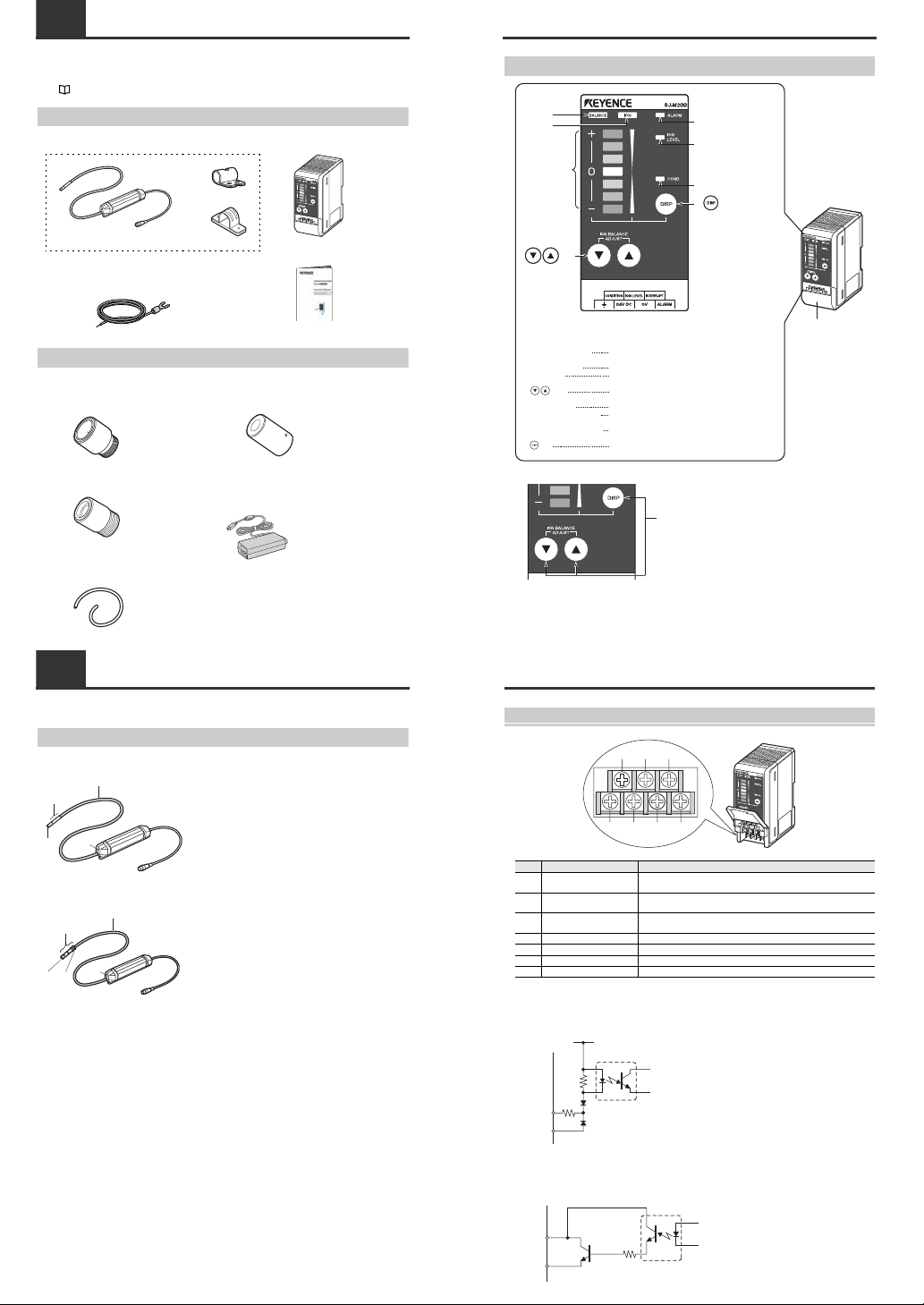
Controller Unit (operation/display section)
Enlarged view of display section
Terminal plate cover
Lights when the charged level of the target object is
displayed.
Lights when the ion emission level is being displayed.
Indicates the charged level of the target object.
Also, indicates the ion emission level.
Used for adjusting the ion balance and for selecting setting
items.
Lights when an alarm occurs.
Lights when the ion emission level has fallen below the set
value due to dirt or wear of the electrode probe.
Lights when the charged level of the target object is high
and static cannot be completely eliminated.
Used for determining setting items and for switching the
display.
Ion balance
indicator
Ion level
indicator
Ion monitor
keys
key
Alarm indicator
Ion level alarm indicator
Condition alarm indicator
Ion balance indicator
Ion level indicator
Ion monitor
keys
Alarm indicator
Ion level alarm indicator
Condition alarm indicator
key
(1)
(2)
(3)
(4)
(5)
(6)
(7)
(8)
(1)
(2)
(3)
(4)
(5)
(6)
(7)
(8)
* Button function and layout are common to SJ-M100, 200
* The color of plate of M200 is different from that of M100.
1-3
Names and Functions of Parts
Controller Unit (I/O terminal section)
* Common to SJ-M100, 200
■ Input circuit diagram
■ Output circuit diagram
Number
Name Function
(1)
Condition alarm output
terminal
Outputs when static elimination performance is influenced by excessive
charge. (N.O.)
(2)
Ion level alarm output
terminal
Outputs when the ion emission level drops. (N.O.)
(3)
Static elimination stop input
terminal
Static elimination can be turned ON/OFF by shorting this terminal with
(6).
(4) Ground terminal Be sure to connect a Class D earth (maximum resistance of 100 Ohms).
(5) DC power terminal 24 VDC ±10%
(6) 0V terminal 0V for power and 0V for I/O
(7) Alarm output terminal Outputs when an alarm occurs. (N.C.)
(1)
(4) (5) (6) (7)
(2) (3)
+24V
3kΩ
INPUT( (3) )
0V( (6) )
Input a no-voltage contact (relay, etc.)
or NPN open collector to INPUT and 0V.
[ (3) (static elimination stop input)]
OUT
DC40V
100mA
0V( (6) )
Open collector output
[ (2) (ion level alarm output), (1) (condition alarm output), (7) (alarm output)]
3
Page 5
2-1 Before Installation
This section describes the static elimination performance of the SJ-M100/200 Series.
Before you install the SJ-M100/200 Series, fully calculate the distance between the Static Elimination
Head up to the target object and the time required for static elimination.
About Static Elimination Performance
The following shows a typical example where static is eliminated from an aluminum plate (20 pF) 150 x
150 mm square charged to +1000 V by the SJ-M100/200 Series.
■ Static elimination time
The following graphs show typical examples of the relationship between static elimination time and
static charged voltage.
Measurement condition:
Applied voltage +1000 V
150 mm x 150 mm plate monitor (20 pF) used
Installation distance 300 mm
Air purge pressure 0.5 MPa
Cable length 2 m
SJ-M010/020 SJ-M020G
SJ-M020+SJ-MS2 SJ-M020+SJ-MS1
0
100
200
300
400
500
600
700
800
900
1000
0 0.2 0.4 0.6 0.8 1
Charged level (V)
Time (secs)
0
100
200
300
400
500
600
700
800
900
1000
0 0.1 0.3 0.4 0.5 0.6
Time (secs)
Charged level (V)
0.2
0
100
200
300
400
500
600
700
800
900
1000
0 0.2 0.6 0.8 1.21 1.4
Time (secs)
Charged level (V)
0.4
0
100
200
300
400
500
600
700
800
900
1000
01 34 76589
Time (secs)
Charged level (V)
2
2-1
Before Installation
SJ-M020+SJ-MS3 (500 mm) SJ-M020+SJ-MS4 (500 mm)
SJ-M020+SJ-ML SJ-M020+SJ-ML2
SJ-M020+SJ-ML1 SJ-M020+SJ-ML3 (500 mm)
SJ-M020+SJ-ML4 (500 mm)
0
100
200
300
400
500
600
700
800
900
1000
01 34 657
Time (secs)
Charged level (V)
2
0
100
200
300
400
500
600
700
800
900
1000
01 5 7 11912
Time (secs)
Charged level (V)
3268104
0
100
200
300
400
500
600
700
800
900
1000
0 0.2 1 1.4
Time (secs)
Charged level (V)
0.60.4 1.20.8
0
0.1
0.2
0.3
0.4
0.5
0.6
0.7
0.8
0.9
1
0 0.5 2
Time (secs)
Charged level (V)
1.51
0
0.1
0.2
0.3
0.4
0.5
0.6
0.7
0.8
0.9
1
0 0.5 2.5 4 4.5 51.5132 3.5
Time (secs)
Charged level (V)
0
0.1
0.2
0.3
0.4
0.5
0.6
0.7
0.8
0.9
1
0 0.5 2.5 4 4.5 51.5132 3.5
Time (secs)
Charged level (V)
0
0.1
0.2
0.3
0.4
0.5
0.6
0.7
0.8
0.9
1
01 5 891032647
Time (secs)
Charged level (V)
2-1
Before Installation
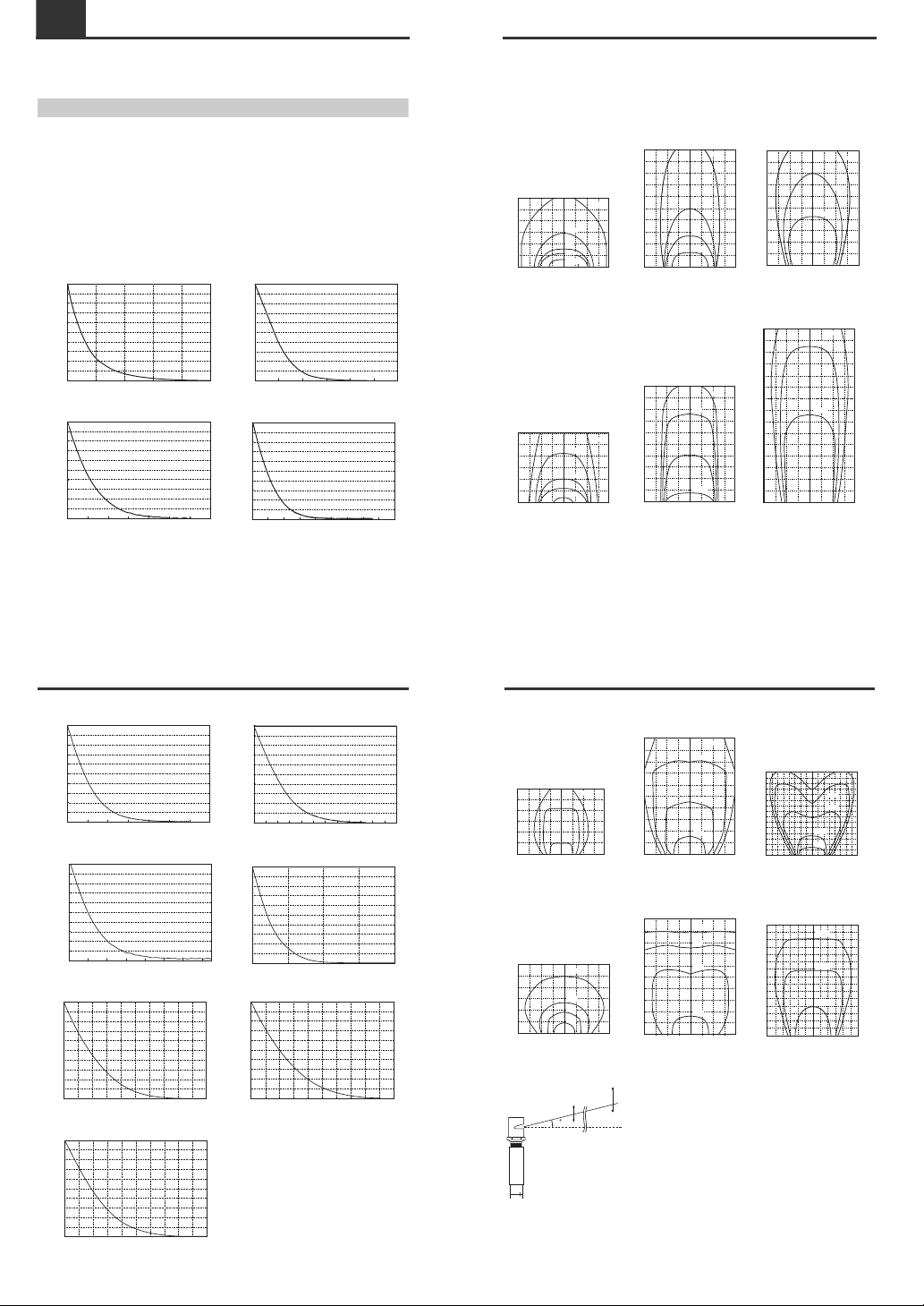
■ Static elimination area
The following graphs show the relationship between the time required for eliminating static from a
target object charged between +1000 to +100 V and the distance from the charged object up to the
Static Elimination Head.
Model No. SJ-M010/020
Air flow rate 20 Nl/min
(pressure 0.01 MPa)
Air flow rate 60 Nl/min
(pressure 0.05 MPa)
Air flow rate 250 Nl/min (pressure
0.5 MPa)
Model No. SJ-M020G
Air flow rate 20 Nl/min
(pressure 0.02 MPa)
Air flow rate 60 Nl/min
(pressure 0.12 MPa)
Air flow rate 200 Nl/min (pressure
0.5 MPa)
200150 100 50 0 50 100 150 200
mm
mm
0
200
400
600
100
300
500
0.5sec
1sec
2sec
5sec
10sec
200 100150 50 500 100 150200
mm
mm
100
0
200
400
500
600
700
800
900
300
1000
0.5sec
1sec
2sec
5sec
200150 100 50 500 100 200150
mm
mm
300
0
150
450
750
1050
1500
600
900
1200
1350
0.5sec
1sec
2sec
200150 100 50 0 50 100 150 200
mm
mm
0
200
400
600
100
300
500
0.5sec
1sec
2sec
5sec
10sec
200150 100 50 0 50 100 150 200
mm
mm
0
200
400
600
100
300
500
800
1000
700
900
0.5sec
1sec
2sec
3sec
-200 -150 -100
-50 0 50 100 150 200
mm
mm
0
200
400
600
100
300
500
800
700
900
0.5sec
1sec
1.5sec
2-1
Before Installation
Model No. SJ-M020+SJ-MS1
Air flow rate 20 Nl/min
(pressure 0.03 MPa)
Air flow rate 60 Nl/min
(pressure 0.16 MPa)
Air flow rate 160 Nl/min (pressure
0.5 MPa)
Model No. SJ-M020+SJ-MS2
Air flow rate 20 Nl/min
(pressure 0.02 MPa)
Air flow rate 60 Nl/min
(pressure 0.1 MPa)
Air flow rate 250 Nl/min (pressure
0.5 MPa)
SJ-M020+SJ-MS2/ML2
Static elimination area
200150 100 50 0 50 100 150 200
mm
mm
0
200
400
600
100
300
500
5sec
8sec
10sec
200150 100 50 0 50 100 150 200
mm
mm
0
200
400
600
100
300
500
800
1000
700
900
3sec
5sec
8sec
10sec
400 300 200 100350 250 150 50 0 100 200 300 400
mm
mm
0
200
400
600
100
300
500
800
1000
700
900
1100
1300
1500
1200
1400
50 150 250 350
8sec
2sec
3sec
5sec
7sec
200150 100 50 0 50 100 150 200
mm
mm
0
200
400
600
100
300
500
5sec
8sec
10sec
20sec
200150 100 50 0 50 100 150 200
mm
mm
0
200
400
600
100
300
500
800
1000
700
900
2sec
5sec
8sec
10sec
300 200 100250 150 50 0 100 200 300
mm
mm
0
200
400
600
100
300
500
800
1000
700
900
1100
1300
1500
1200
1400
50 150 250
3sec
1sec
2sec
14
100mm
-50mm
100mm
280mm
-50mm
500mm
4
Page 6

2-1
Before Installation
Model No. SJ-M020+SJ-MS3/ML3 (500 mm)
Air flow rate 140 Nl/min (pressure
0.3 MPa)
Air flow rate 230 Nl/min (pressure
0.5 MPa)
Model No. SJ-M020+SJ-MS4/ML4 (500 mm)
Air flow rate 145 Nl/min (pressure
0.3 MPa)
Air flow rate 240 Nl/min (pressure
0.5 MPa)
200150 100 50 0 50 100 150 200
mm
mm
0
200
400
600
100
300
500
800
1000
700
900
3sec
5sec
7sec
200150 100 50 0 50 100 150 200
mm
mm
0
200
400
600
100
300
500
800
1000
700
900
1100
1300
1500
1200
1400
5sec
7sec
3sec
8sec
2sec
200150 100 50 0 50 100 150 200
mm
mm
0
200
400
600
100
300
500
800
1000
700
900
7sec
10sec
13sec
200150 100 50 0 50 100 150 200
mm
mm
0
200
400
600
100
300
500
800
1000
700
900
1100
1300
1500
1200
1400
5sec
10sec
15sec
2-1
Before Installation
Model No. SJ-M020+SJ-ML
Air flow rate 20 Nl/min
(pressure 0.02 MPa)
Air flow rate 60 Nl/min
(pressure 0.1 MPa)
Air flow rate 250 Nl/min (pressure
0.5 MPa)
200150 100 50 0 50 100 150 200
mm
mm
0
200
400
600
100
300
500
3sec
10sec
15sec
20sec
200150 100 50 0 50 100 150 200
mm
mm
0
200
400
600
100
300
500
800
1000
700
900
1sec
5sec
10sec
2sec
200150 100 50 0 50 100 150 200
mm
mm
0
200
400
600
100
300
500
800
1000
700
900
1100
1300
1500
1200
1400
0.5sec
1sec
2sec
2-1
Before Installation
■ Appropriate static elimination method
Pay attention to the following points to ensure that static elimination is performed appropriately.
Static elimination cannot be performed accurately at locations where the target object is
touching a metallic body (earthed body).
Eliminate static from the target object at locations where it is not directly touching metallic bodied
(earthed body).
Static will be eliminated from only the surface of the insulated body (board, etc.) that is facing
the Static Elimination Head.
When eliminating static from both sides of a target object, install two SJ-M Series as one SJ-M Series
must be installed on either side of the target object.
Install the Static Elimination Head so that it can be easily accessed, for example, for
replacement of parts and cleaning.
Installation Precautions
■ Installation site
Install the tip of the SJ-M010/020(G) paying attention to the following point.
• Install the Static Elimination Head away from the wall or surrounding
objects.
•
Protect the area around the tip of the Static Elimination Head with silicon,
fluoro-resin or other highly ozone-resistant resin. Ozone that is generated may
cause the metal or resin on the SJ-M010/020(G) to rust, corrode or deteriorate.
Insulating matMetal
Board
Board
Note
CAUTION
The section marked by "*" must not touch the conductor (earthed body).
The adapter nozzle must not touch the conductor (earthed body).
23mm*
10 mm or more
10 mm
or more
10 mm or more
10 mm
or more
Requires 10 mm or more away
from the air outlet
*
● SJ-M010/020(G)
2-1
Before Installation
• Do not install the Static Elimination Head at locations where moving parts of
other equipment and machinery may place stress on the cable. Doing so
might cause the SJ-M010/020(G) Series to malfunction.
■ Interference
The Static Elimination Head may not function properly if there is a conductor (earthed body) located
nearby or if two or more units are used close to each other. In such an installation, refer to the figure
below and maintain the indicated distance between the conductor (earthed body). If a conductor (earthed
body) is located inside the distances indicated below, adjust using the ion balance manual setup.
"Ion Balance Adjustment Function" (page 8)
When two SJ-M Series units are used, refer to the figures below, and install the units so that the
following distances are maintained between the two Static Elimination Heads.
200 mm
or more
20 mm
or more
10 mm
or more
20 mm
or more
20 mm or more
10 mm
or more
200 mm or more
10 mm
or more
20 mm or more
20 mm or more
200 mm or more
When SJ-MS2
is used
When SJ-ML1
is used
When SJ-MS1
is used
200 mm
or more
20 mm
or more
10 mm
or more
20 mm
or more
● SJ-M010/020 (G)
60 mm or more
away from the
nozzle or air outlet
60 mm or more
60 mm or more
60 mm
or more
60 mm or
more away
from the
nozzle or
air outlet
60 mm or more
60 mm or more
60 mm
or more
● SJ-M010/020 (G)
60mm or more
60mm
or more
60mm
or more
35mm or more
● SJ-MS* ● SJ-ML*
60 mm or more
60 mm or more
5
Page 7

2-2 Connection and Installation
This section describes how to connect and install the Static Elimination Head and Controller Unit.
Installing the nozzle/tube
Install the nozzle and the tube to the Static Elimination Head by following the procedures below.
It is recommended that this installation be done prior to "Installing the Static
Elimination Head" in the next section. If not, it may become difficult to install the
Static Elimination Head.
■ Installing the nozzle
Attach the nozzle to SJ-M020(G). Attach and tighten
the nozzle mounting fixture to the nozzle to fasten it in place.
■ Installing the tube
An air tube is applicable to SJ-MS3/4 and SJ-ML3/4. Use
an air tube of OP-75350 (PFA tube 500 mm). Static
elimination power varies depending on the length of the
air tube. Check the length carefully before use.
Before using SJ-MS3/4 or SJ-ML3/4 with an air tube mounted, make the "Tube
Installation Setting" in page 8 effective.
CAUTION
Model name Fastening torque
Between nozzle and nozzle
mounting fixture
2 N·m or less
SJ-MS2/ML2
(between head and adapter)
2–3 N·m or less
SJ-MS3/ML3
(between head and adapter)
7 N·m or less
SJ-MS4/ML4
(between head and adapter)
7 N·m or less
SJ-MS1/ML1
(between resin head and
adapter)
Fasten manually until it stops.
Then use a tool such as
wrench and rotate approx. 2 or
3 times to fasten more. Fix in
your desired direction. If you
fasten a screw too tightly, a
screw section may result in
breakage. Insufficient
fastening may result in
looseness or leakage.
Nozzle mounting fixture
CAUTION
2-2
Connection and Installation
Installing the SJ-M Series
Install the SJ-M Series at locations where static electricity is generated or is likely to be generated.
■ Installing the Static Elimination Head
There are two ways of installing the Static Elimination Head, with or without the mounting fixtures.
When installing the SJ-M Series, observe the minimum bending radius of all
provided cables. Also, do not install the SJ-M Series with the cables deformed
by staples or other objects. Doing so might cause the SJ-M Series to
malfunction.
● When the mounting fixture is used:
When installing the SJ-M010/020(G), prepare tapped
mounting holes, and install the SJ-M010/020(G) with
M3 screws at a tightening torque of 1 Nm or less (M4
screws: 1 Nm or less).
The M3 screws and bundling band for fastening the
mounting fixture must be prepared separately.
● When the mounting fixture is not used:
When mounting the SJ-M010/020(G) using the M3 set
screws, tighten at a torque of 0.1 Nm or less.
Install within the allowable mounting fixture range indicated in the external
dimension drawings. Otherwise, static may not be eliminated properly.
CAUTION
M3 ta
p
M4 tap
M3 tap
M4 tap
•SJ-M010
•SJ-M020 (G)
Install the mounting fixture within the
allowable mounting fixture range
indicated in the external dimension
drawings. Otherwise, static may not be
eliminated properly.
Make a space of 30 mm or more
around the drive unit. Otherwise,
the unit may be damaged.
Important
CAUTION
M3 set screw (flat)
28 mm or more
Limit the tightening torque to
0.1 Nm. Exceeding this torque
might damage the set screws.
CAUTION
Important
2-2
Connection and Installation
■ Installing the discharge prevention cap (option)
An optional discharge prevention cap is available to prevent the risk of accidentally touching the Static
Elimination Head and causing discharge during maintenance work, for example. Use this cap if
necessary.
■ Installing the cap
Install the discharge prevention cap as shown in the following figures, and fasten in place using the set
screws (provided).
(Tightening torque: SJ-M010/020(G): 0.04 Nm or less)
■ Installing the Controller unit
Install and fasten in place
so that the end surface of
the cap is at this position.
OP-75354
● SJ-M010/020(G) (cross-section view)
Mount the Controller Unit on the DIN rail.
2-2
Connection and Installation
Connecting Cables
When you have finished installing the Static Elimination Head, connect the earth lead, Static
Elimination Head connector cable and power supply.
■ Connecting the earth lead
Open the terminal plate cover on the Controller
Unit, and connect the earth lead to the GND
connection terminal.
Be sure to connect a Class D earth (maximum
resistance of 100 Ohms).
To prevent electric shock and to ensure accurate static elimination, be sure to
connect a Class D earth (maximum resistance of 100 Ohms).
■ Connecting the cable
Connect the Static Elimination Head
connector cable to the Controller Unit.
Connect this cable with the power
turned OFF.
When installing the Controller Unit
away from the Static Elimination
Head, use the optional extension
cable (SJ-C3).
■ Connecting the power supply
Connect the power supply according to either
of the following methods.
24 VDC power supply
Connect a 24 VDC output power supply
having sufficient power capacity margin to the
power terminals (terminals (5) and (6))
"Controller Unit (I/O terminal section)" (page
3)
Be sure to connect
a Class D earth
(maximum resistance
of 100 Ohms).
WARNING
Match and connect
the end of the connector
cable to the inlet on the
Controller Unit.
To 24 VDC
power supply
To 24 VDC
power supply
6
Page 8

2-2
Connection and Installation
AC adapter (SJ-U2)
Connect the AC adapter to the connector on the side of
the Controller Unit.
The AC adapter is available as an option.
3-1 SJ-M Series Operations
This section describes operation of the SJ-M Series.
Setup Flow
The setup flow for setting up the SJ-M Series is as follows.
■ When the SJ-M Series is turned ON for the first time
■ Moving between modes
Modes on the SJ-M series change as follows.
The unit starts up in the Run mode after the power is turned ON or after static elimination is
stopped.
Blink alternately at high speed
Blink
When the power is turned ON for the first time after purchase, the
SJ-M Series starts up at the “High temperature use setting” in the
Setup mode.
At this time, static elimination is not performed.
Select the appropriate settings using , and press .
Enter the Run mode, and start static elimination.
"High temperature use setting" (page 7)
Make the settings matched to the actual operating
environment. Incorrect settings may cause accidents
or malfunction.
Important
<
R
unmod
e
><S
electmode
>
<I
onBalanceManua
lAdjustmentmod
e
>
<S
etupmod
e
>
One lit Blink alternately Blink alternately fast
Press for
a short time.
"BALANCE" lit
Hold down for
at least 1 second.
Hold down for
at least 1 second.
Hold down and
simultaneously
for at least 1 second.
Tip
<High temperature setting>
3-1
SJ-M Series Operations
Run Mode
Regular static elimination operation is performed in the Run mode.
The following functions are available in the Run mode.
●Ion monitor functions
"Ion Monitor Functions" (page 8)
●Alarm output functions
"Alarm Output Functions" (page 9)
●Confirmation of ion balance adjustment values
Select Mode
In this mode, select the setting items to change in the Setup mode
Setup Mode
In this mode, change the settings of the items selected in the Select mode.
A
B
C
E
D
Blink alternately
1
424
3
Operations in the Select mode
Press for a short time:
Enters the Setup mode for the currently selected item.
Hold down for at least 1 second:
Exits the Select mode, and returns to the Run mode.
: Move the cursor up and down.
On the ion monitor, the currently selected items are lit (green), and the items
whose defaults have been changed are lit (red).
Items that satisfy both of these conditions blink red and green alternately.
The following describes each of the items in the Select mode:
:
Ion level alarm, sensitivity setting
:
Condition alarm, sensitivity setting
:
High temperature use setting
:Tube head setting (I.C.C. ON/OFF)
:
Initialization of settings
1
424
3
Blink alternately fast
Operations in the Setup mode
:Applies the setting at the selected conditions.
:Move the cursor up and down.
The following describes each of the items in the Setup mode:
1
424
3
3-1
SJ-M Series Operations
■ Ion level alarm sensitivity setup
Sets the sensitivity at which the ion level alarm is output.
(1) High sensitivity (red): Alarms are easily output.
(2) Medium sensitivity (orange):
(3) Low sensitivity (green): Alarms are not easily output.
(4) No sensitivity (red): No alarm output.
Default is “Low sensitivity.”
"Ion level alarm output function (ION LEVEL)" (page 9)
■ Condition alarm sensitivity setup
Sets the sensitivity at which the condition alarm is output.
(1) High sensitivity (red): Alarms are easily output.
(2) Medium sensitivity (orange):
(3) Low sensitivity (green): Alarms are not easily output.
(4) No sensitivity (red): Alarms are easily output.
Default is “Low sensitivity.”
"Condition alarm output function (COND)" (page 9)
■ High temperature use setting
Make the settings matched to the operating environment.
(1):High temperature/nitrogen environment (red)
(2):Use in environments other than the above (green)
Default is (2).
1
2
3
4
Blink
Tip
1
2
3
4
Blin
k
Tip
1
2
Blink
High temperature use (+60°C to +80°C)
Tip
Make the settings matched to the actual operating
environment. Incorrect settings may cause
accidents or malfunction.
Important
7
Page 9

3-1
SJ-M Series Operations
■ Tube Installation Setting
Advance to the tube head setting from the Select mode in page 7,
and select either of the followings.
(1) Normal nozzle (green) (Default)
(2) Tube nozzle (red)
■ Initialization of settings
Returns settings to their defaults.
(1) Press , or for a short time:
Returns to the Select mode without initializing the settings.
(2) Hold down for at least 2 seconds:
Initializes the settings and returns to the Select mode.
When settings are initialized, the ion monitor indication moves
towards both ends of the display.
Blin
k
Blin
k
Select an appropriate nozzle according to the
head. Incorrect setting may cause accidents or
malfunction. When the tube nozzle is selected, the
ion level alarm will not be output correctly.
Important
1
Blink
Tip
3-1
SJ-M Series Operations
Ion Balance Manual Adjustment Mode
In this mode, you can adjust the zero point, the point for reference for the I.C.C. function.
Ion Balance Adjustment Function
The SJ-M Series automatically senses the charged level of the target body by the I.C.C. function to
automatically control the generated amount (balance) of plus and minus ions.
The zero point, the point for reference for the I.C.C. function, is adjusted before the SJ-M Series is
shipped from the factory. However, in some environments, the zero point sometimes drifts. If this
reference zero point drifts, adequate static elimination cannot be maintained. For this reason, you can
adjust the SJ-M Series to the desired zero point.
Do not turn the power OFF while the ion balance is being adjusted (about 1
minute).
■ Setting the ion balance
1 Hold down for at least one second to enter the ion
balance manual adjustment mode.
The ion balance indicator blinks.
CAUTION
Hold down for at
least 1 second.
3-1
SJ-M Series Operations
Holding down for about
three seconds when setting
the ion balance clears the
preset ion balance zero
point and returns the ion
balance to its default
setting.
2 Set the ion balance using .
The LED on the ion monitor corresponding to the set value lights.
3 Press to end ion balance setup.
Note
During this operation,
the ion monitor indication
moves towards both ends
of the display.
Key Function
Key Shifts the zero point in the + direction.
Key Shifts the zero point in the – direction.
Blink fast
The mode changes to the Run mode.
After you have finished setting up the ion balance, the ion
balance indicator will blink fast for about 1 minute, indicating
that the ion balance setup is being written to memory.
After you have finished setting up the ion
balance, do not change the ambient
environment for about 1 minute. If you do, the
zero point sometimes cannot be set accurately.
Note
3-2 Ion Monitor Functions
This section describes the ion monitor functions of the SJ-M Series.
Ion monitor functions are enabled in the Run mode.
Ion Monitor Functions
The charged level of the target object and the level of ions generated from the static elimination head
are indicated on the ion monitor.
The ion monitor indication can be switched by .
■ Charge monitor
This monitor indicates the charged and decharged
states of the target object.
The indication of this monitor fluctuates towards the
+ and – sides according to the charged level. The
further the indication is away from the center LED,
the larger the charged level. When static elimination
is completed, the indication returns to the center
LED so that you can easily tell how static
elimination is progressing.
The ion balance indicator lights when the charge
monitor is operating.
■ Ion level monitor
This monitor indicates the level of ions being
generated by the Static Elimination Head.
The level of plus ions being generated is indicated
on the upper side, while the level of minus ions is
indicated on the lower side. The further the
indication is away from the center LED, the larger
the level of ions. In a state where ions are being
sufficiently generated, both ends of this monitor light
(green).
The ion balance indicator lights when the ion level
monitor is operating.
Red
Orange
Orange
Green
Orange
Orange
Red
Green
Green
Orange
Red
Orange
Green
Green
Max.
+ ion
Min.
Min.
- ion
Max.
8
Page 10

3-3 Alarm Output Functions
This section describes the alarm output functions of the SJ-M Series.
Alarm Output Functions
■ Alarm output function (ALARM)
The alarm indicator blinks (red) and an alarm signal
(control output (N.C.)) is output, for example, when
internal circuits are damaged or abnormal discharging
occurs. When an alarm signal is output, static
elimination is forcibly stopped.
Alarm output turns ON even in a static elimination
stopped state (including forced static elimination stop).
■ Ion level alarm output function (ION LEVEL)
The ion level alarm indicator lights and an alarm signal
(control output (N.O.)) is output when the level of
generated ions drops due to a dirty or worn electrode
probe, for example. When an alarm signal is output,
static elimination is not stopped.
Alarm output can be adjusted in three stages
according to the level of ions generated.
The default setting for the ion level alarm sensitivity
setting is Low.
The ion level alarm serves as a guideline for learning
when to perform maintenance on the electrode probe.
As static elimination is continued, be sure to turn the
power OFF before starting maintenance on the
electrode probe.
The ion level alarm output function is enabled in the
Run mode.
"Ion level alarm sensitivity setup" (page 7)
■ Condition alarm output function (COND)
The condition alarm output indicator lights and an
alarm signal (control output (N.O.)) is output when
static elimination performance is influenced by an
excessive charge on the target object. When an alarm
signal is output, static elimination is not stopped.
Alarm output can be adjusted in three stages
according to the installation environment. The default
setting for the condition alarm sensitivity setting is
Low.
The ion level alarm output function is enabled in the
Run mode.
"Condition alarm sensitivity setup" (page 7)
3-4 Other Functions
This section describes the abnormal discharge detection and static elimination stop functions of the SJM Series.
Abnormal Discharge Detection Function
To prevent trouble, the generation of ions is stopped when abnormal discharging caused by
condensation on the electrode probe tips or adhesion of debris, for example, is detected. At this time,
the alarm indicator and ion monitor blink to inform you that an abnormality has occurred. For details of
the indicated state on the Controller Unit (operation/display section), see "During an alarm (level 2)"
( page 14).
Static Elimination Stop Function
Static elimination only can be turned OFF in a powered ON state by two methods: by shorting the static
elimination stop input and 0V terminals on the Controller Unit (I/O terminal section), or by holding down
on the Controller Unit (operation/display section) simultaneously for about three seconds.
When static elimination stop input has been performed on the Controller Unit (operation/display
section), this state can be canceled by holding down simultaneously for about three seconds.
For details on indication states on the Controller Unit (operation/display section) when static elimination
stop input is canceled, see "Static elimination stop input (operation/display section)" ( page 14).
■ Static elimination stop input
Static elimination is stopped by either of the following methods.
By operation on the Controller Unit (I/O terminal section):
Short the static elimination stop input and 0V
terminals to stop static elimination.
The center LED of the ion monitor blinks (red).
"Controller Unit (I/O terminal section)" (page
3)
To 24 VDC
power supply
To 24 VDC
power supply
3-4
Other Functions
By operation on the Controller Unit (operation/display section):
Hold down simultaneously for about three
seconds to stop static elimination.
The three center LEDs of the ion monitor blink
(red).
Air Purge Function
Clean air, dry air must be supplied to the SJ-M010/020(G) from the Air Input Unit. The air purge
performs two roles. It prevents dirt from sticking to the electrode probe and extends the static
elimination area.
* The pressure value at the neck of the air duct is indicated as the air pressure.
Use clean air or dry air of temperature –25°C, and of mesh size of about 0.01 μm.
• Be sure to limit the air pressure to 0.5 MPa. Exceeding this limit may cause
accidents or malfunction.
• Be sure to use clean air, dry air as the air for supplying to the Static
Elimination Head. Moisture or oil contained in the air or nitrogen may cause
discharge inside the Static Elimination Head, which may result in accidents
or malfunction.
■ Relationship between air press and flow rate
The figure on the right shows the relationship
between the flow rate and pressure of the
supplied air.
Select an air compressor having sufficient
flow rate capacity referring to this figure
Hold down for
at least 3 seconds.
CAUTION
0
50
100
150
200
250
300
350
0 0.2 0.40.1 0.3 0.5 0.6
Air pressure [MPa]
Supply flow rate [NL/min]
SJ-M020G
SJ-M020G(1.2m)
SJ-M020G(0.6m)
SJ-M020
SJ-M020(1.2m)
SJ-M020(0.6m)
By cord length
0
50
100
150
200
250
300
350
0 0.2 0.4 0.6
SJ-M020G
SJ-M020G+SJ-MS2
SJ-M020G+SJ-MS1
SJ-M020G+SJ-MS3
SJ-M020G+SJ-MS4
SJ-M020G+SJ-ML
Air pressure [MPa]
Supply flow rate [NL/min]
0
50
100
150
200
250
300
350
0 0.2 0.4 0.6
SJ-M020
SJ-M020+SJ-MS2
SJ-M020+SJ-MS1
SJ-M020+SJ-MS3
SJ-M020+SJ-MS4
SJ-M020+SJ-ML
Air pressure [MPa]
Supply flow rate [NL/min]
By nozzle type (SJ-M020G) By nozzle type (SJ-M020)
3-4
Other Functions
■ Relationship between installation distance and static elimination speed
according to air flow rate
The relationship between static elimination
speed and installation distance between the
Static Elimination Head varies according to
the air flow rate.
Select an air supply flow rate referring to the
typical example on the right.
Measurement conditions:
Static elimination time in +1000V to +100V
range
150 mm x 150 mm plate monitor (20 pF)
used
0.00
0.50
1.00
1.50
2.00
2.50
3.00
4.00
3.50
0 150 25050 100 200
Installation distance (mm)
Static elimination speed (secs)
20NL
60NL
250NL
SJ-M020
0.00
1.00
2.00
3.00
4.00
5.00
6.00
8.00
7.00
0 150 25050 100 200
20NL
40NL
160NL
Installation distance (mm)
Static elimination speed (secs)
0.00
1.00
2.00
3.00
4.00
5.00
6.00
8.00
7.00
0 150 25050 100 200
20NL
60NL
250NL
Installation distance (mm)
Static elimination speed (secs)
0.00
1.00
3.00
5.00
7.00
9.00
11.00
15.00
13.00
0 150 25050 100 200
60NL
140NL
250NL
Installation distance (mm)
Static elimination speed (secs)
0.00
1.00
3.00
5.00
7.00
9.00
11.00
15.00
13.00
0 150 25050 100 200
20NL
60NL
250NL
Installation distance (mm)
Static elimination speed (secs)
SJ-|M020+SJ-MS1 SJ-M020+SJ-MS2
SJ-M020+SJ-MS3 tube 500 mm SJ-M020+SJ-ML
9
Page 11

3-4
Other Functions
■ Relationship between installation distance and wind speed according to air
flow rate
The relationship between wind speed and static elimination head installation distance varies according
to the air flow rate
Adjust the air supply flow rate referring to the following figures.
75
100 150 200 250 300 350500 400mm
mm
50
25
0
-25
-50
-75
10m/s 2m/s 1m/s
75
200 300 400 500 600 7001000 1000mm
mm
50
25
0
-25
-50
-75
800 900
10m/s 5m/s
1m/s
2m/s
100
200 300 400 500 600 7001000 1500mm
mm
50
75
25
0
-25
-50
-75
-100
800 900 1000 1100 1200 1300 1400
10m/s20m/s
5m/s
1m/s
1m/s
2m/s
2m/s
Air flow rate 250 Nl/min (pressure 0.5 MPa)
Air flow rate 20 Nl/min (pressure 0.01 MPa) Air flow rate 60 Nl/min (pressure 0.08 MPa)
3-4
Other Functions
■ How to supply air
Supply air from the SJ-M010/020(G)'s Air Input Unit as
shown in the figure on the right.
Joints and tubes must be prepared separately.
● Recommended joint
We recommend using a tube fitting (tube dia. 6mm, 8mm) made by PISCO for a joint to the Air Input
Unit.
• Be sure to limit the tightening torque to 0.7 Nm. Tightening beyond this limit
may cause an accident or a malfunction.
• Be sure to use the Air Input Unit. Using a different air supply may cause an
accident or a malfunction.
Rc1/8
Tube
Tube dia.6 mm: PC6-01
Tube dia.8 mm: PC8-01
CAUTION
3-4
Other Functions
I.C.C. Setting
The I.C.C. (Ion Current Control) can be turned on and off.
Turning off the I.C.C. allows the ion balance adjustment function to generate positive and negative ions
at a fixed ratio.
<Run mode> <Select mode>
Either of them lit Blink alternately
Hold down
for at least
1 second
Hold down for at
least 1 second
simultaneously
ChangeChangeChange
Blink
①
②
Blink
Change the 4th LED from the top in the Select mode.
Press for a short time : advances to the Setup mode
of the selected item
Hold down for at least 1 second: exits the Select mode and
returns to the Run mode
: moves the cursor up and
down
On the ion monitor, the currently selected items are lit in green and the
items whose default have been changed are lit in red.
I.C.C. is set at ON by default setting.
Items that satisfy both of these conditions blink in red and green
alternately.
Advance to the tube head setting from the Select mode in page 7, and
select either of the followings.
(1) Normal nozzle (green) (Default)
(2) Tube nozzle (red)
Select an appropriate nozzle according to the
head. Incorrect setting may cause accidents or
malfunction. When the tube nozzle is selected, the
ion level alarm will not be output correctly.
Important
4-1 About Maintenance
Maintenance must be performed periodically to ensure that the static elimination performance of the
SJ-M Series is fu lly demonstrated. Maintenance personnel should thoroughly read the descriptions
under "Safety Precautions" ( page 1), and perform maintenance paying attention to the following
points.
About Maintenance
•
The SJ-M Series uses high voltage. Before starting maintenance, be sure to
turn the power OFF. Failure to do so might result in electric shock or
malfunction.
•
Do not directly touch the electrode
probe. Take care not to touch these
probes even if the power is turned OFF.
Directly touching these probes may
cause personal injury.
When the SJ-M Series is used for a long period of time, the electrode probe becomes dirty due to the
adhesion of dust and dirt.
If the ion level alarm indicator lights, clean the electrode probe. If the electrode probe is used in a dirty
or dusty state, static elimination performance can no longer be fully demonstrated, resulting in
accidents or malfunction. We recommend periodically cleaning the electrode probe (as a guideline,
once every two weeks in a regular operating environment though this depends on the installation
conditions).
If cleaning the electrode probe does not improve the static elimination performance, or the ion level
alarm indicator frequently lights, replace the electrode probe.
WARNING
10
Page 12

4-2
Performing Maintenance on the Electrode probe
When the SJ-M Series is used for a long period of time, the electrode probe becomes dirty due to the
adhesion of dust and dirt.
If the electrode probe is used in a dirty or dusty state, static elimination performance can no longer be
fully demonstrated, resulting in accidents or malfunction. Be sure to periodically perform maintenance
on the electrode probe.
Performing Maintenance on the Electrode probe
• Before removing the Electrode Unit, turn the SJ-M Series OFF.
• Do not directly touch the electrode probe with your hands. Doing so may
cause personal injury. Pay attention to this when performing maintenance
on the electrode probe.
■ How to clean the electrode probe
Clean the electrode probe gently with a cotton wool bud
moistened with alcohol.
■ How to replace the electrode probe
Note: If cleaning the electrode probe does not improve static elimination performance, or the ion level
alarm indicator frequently lights, a probable cause is that the electrode probe has reached the end of its
service life.
Electrode replacement units for SJ-M020 (OP-51607) and for SJ-M020G (OP-75351) are available in
options.
● How to remove and install the electrode probe
The electrode probe can be removed by holding the tip of
the electrode probe and turning counterclockwise, and
installed by turning clockwise.
WARNING
Rotate while
holding this area.
5-1 Timing Charts
This section provides timing charts for SJ-M Series.
■ Ion generation control timing chart
Indicator states when static elimination is OFF
Normal static elimination OFF
<during static elimination stop
input (terminal)>
The center LED of the ion monitor blinks (red).
■ Input response timing chart
Normally ON Normally OFF Normally ON Forced OFF Normally ON Normally OFF Normally ON
Static elimination
stop input (terminal)
ON
OFF
Static elimination
stop input (controller)
ON
OFF
Ion emission state
Unit indicator
Emitting
No emissions
Alarm output
ON
OFF
Forced OFF Forced OFFNormally ONNormally OFF
Max. 15 ms Max. 1 s
Static elimination
stop input (unit)
ON
OFF
Ion emission
state
Emitting
No emissions
Normal static elimination OFF <during
static elimination stop input (controller)>
The three center LEDs of the ion monitor
blink (red).
5-1
Timing Charts
■ Ion level alarm output timing chart
■ Condition alarm output timing chart
■ Alarm output timing chart
Power
ON
OFF
Static elimination
stop input (terminal)
ON
OFF
Static elimination
stop input (controller)
ON
OFF
Alarm indicator
Blinking
OFF
Alarm output (N.C.)
ON
OFF
Ion emission
Emitting
No emissions
Ion level indicator
Max. 10s
Blinking
OFF
Ion level alarm
output (N.O.)
ON
OFF
When the ion level alarm is output,
removing the cause of the alarm can
restore the normal state. One way of
restoring the normal state is to
perform maintenance on the electrode
probe.
For details on electrode probe
maintenance, see "Performing
Maintenance on the Electrode probe"
( page 11).
Power
ON
OFF
Alarm indicator
Blinking
OFF
Alarm output (N.C.)
ON
OFF
Ion emission
Emitting
No emissions
Condition indicator
Blinking
OFF
Condition alarm
output (N.O.)
ON
OFF
Max. 10s
Static elimination
stop input (terminal)
ON
OFF
Static elimination
stop input (controller)
ON
OFF
When the condition alarm is output,
removing the cause of the alarm can
restore the normal state. One way of
restoring the normal state is to
improve the installation environment.
Power
ON
OFF
Static elimination
stop input
ON
OFF
Alarm indicator
Blinking
OFF
Alarm output (N.C.)
ON
OFF
Ion emission
Emitting
No emissions
Max. 10 s
When the alarm is output, the normal
state can be restored by performing
one of the two available restore
methods depending on the cause of
alarm output.
For details on how to restore the
normal state, see “During an alarm
(levels 1, 2)” ( page 14).
5-2 Specifications
This section provides the specifications of the SJ-M100/200 Series.
■ Static Elimination Head/Controller Unit
*1: Values obtained at an installation distance of 50 mm and air flow rate of 60 Nl/min (ambient operating temperature +20
to +30°C, ambient operating humidity 40 to 60% RH) (without nozzle)
*2: Values obtained at an installation distance of 50 mm and air flow rate of 20 Nl/min (ambient operating temperature +20
to +30°C, ambient operating humidity 40 to 60% RH) (without nozzle)
*3: Inquire for derating of humidity/pressure in environments exceed +35°C. Use
clean or dry air at a temperature of -20°C or less as the supply fluid. And the
air pressure is different by a model of a nozzle at least (the right chart).
*4: During regular use, supply air at a supply fluid temperature of +40°C or less.
*5: These values are for the High-pressure Cable Unit only. The ambient
operating temperature is 0 to +40°C at other parts.
*6: When the ambient temperature exceeds +40°C, perform derating according to
the following figures.
*7: As for SJ-M010, a combination with SJ-M200 is possible, too.
● Temperature/humidity derating graph
Model
Static Elimination Head
SJ-M010
*7
SJ-M020/SJ-M020 (1.2M)/SJ-M020 (0.6M)/
SJ-M020G/SJ-M020G (1.2M)/SJ-M020G (0.6M)
Controller Unit SJ-M100 SJ-M200
Voltage application method Pulse AC
Applied voltage ±5.5 kV
Rated output voltage ±6 kV
Ion balance control method I.C.C. method
Static elimination time 0.5 sec. max.
*1
Ion balance ±15 V or less
*2
Max. air pressure 0.001 to 0.5 MPa
*3
Control input
Static elimination stop
input
No-voltage input
Control output
Alarm output
NPN open collector
100 mA 40 V or less
Ion level alarm output
Condition alarm output
Rating
Power voltage 24 VDC ±10%
Current consumption 450 mA max.
Environmental
resistance
Operating
ambient
temperature
Head 0 to +80°C
*4, 5, 6
Controller 0 to +40°C
Operating ambient
humidity
35 to 65%RH
Weight
Static Elimination Head Approx. 600 g
Approx.
540 g
Approx.
480 g
Approx.
600 g
Approx.
540 g
Approx.
480 g
Controller Unit Approx. 300 g
Nozzle Min. air pressure
without nozzle 0.001MPa (2.6Nl/min)
SJ-ML 0.02MPa (20Nl/min)
SJ-MS/ML1 0.03MPa (20Nl/min)
SJ-MS/ML2 0.02MPa (20Nl/min)
SJ-MS/ML3 0.08MPa (50Nl/min)
SJ-MS/ML4 0.08MPa (50Nl/min)
0.6
0.5
0.4
0.3
0.2
0.1
0
0 1020304050607080
70
60
50
40
30
20
10
40 50 60 70
80
0
Ambient operating humidity (% RH)
Ambient operating temperature (°C)
Max. operating pressure (MPa)
Ambient operating temperature (°C)
11
Page 13

5-2
Specifications
■ AC Ada pte r
*The AC cable is for domestic use only (voltage rating 125 V).
Model SJ-U2
Rating
Rated input 100 to 240 VAC (50/60 Hz)
Rated output 24 VDC 2.65 A
Environmental resistance
Operating ambient temperature 0 to +35°C
Operating ambient humidity 20 to 80% (condensation not allowed)
Weight Approx. 250 g
5-3 External Dimensions
This section presents the external dimensions of the SJ-M Series.
■ Body
Static Elimination Head
Controller Unit SJ-M100/200
60
24
8.5
191
181
131
5
5
22
34
2.5
34.5
58
11.5
3
51
24
35
φ15
Rc 1/8
+
0.5
0
4.2 mm dia. cable length 2 m
(min. bend radius 50)
(allowable mounting
fixture range)
6 mm dia. cable length 300 mm
(min. bend radius 15)
2- φ4.4 (thru hole)
(male tapered
screw)
φ10
6 mm dia. cable length 300 mm
(min. bend radius 15)
2- φ4.4(thru hole)
24
3
φ15
51
191
181
9 mm dia. cable length
2 m, 1.2 m, 0.6 m
(min. bend radius 50)
24
60
24
(allowable mounting
fixture range)
58
φ10
φ12
11.5
5
131
5
8.5
34
2.5
Rc 1/8
(male tapered
screw)
22
34.5
SJ-M010
SJ-M020 (G)
5
70
120
32
36
46
7650
5-3
External Dimensions
■ Mounting fixture
■ Extension cable (SJ-C3)
■ AC adapter (SJ-U2)
* For details of the AC cable, contact the KEYENCE sales office in your district.
t=0.8
3.2
18
3.2
9
9.8
14
2.611.8
2- 3.4
28.2
20
10
2-long hole *
(Installation hole)
Mounting fixture (top)
10.5
t=0.8
10.2
3.4
2.6
* Long hole dimensions
Mounting fixture (bottom)
2-φ3.4
30
20
10
3
Mounting fixture (for SJ-M010)
Mounting fixture (for SJ-M020)
6 mm dia.
cable length 3 m
49
φ15.5
51
φ15
(37.5)
7
ø16
(10.3)
(16.3)
(12.5)
(14)
28
ø3.5
1800
114.5
50.5
■ Discharge prevention cap
60.5
11.5
25
17
M3 set screw
For SJ-M010 (OP-51614)
5-3
External Dimensions
■ Nozzle
SJ-ML SJ-ML1
SJ-MS1 SJ-ML2
SJ-MS2 SJ-ML3
SJ-MS3 SJ-ML4
SJ-MS4
SJ-M020
SJ-M020G
M12xP1
72
13
Rc 1/8
6.5
20
6.5
31
SJ-M020
SJ-M020G
72
M12xP1
13
31
6.5
6.5
20
(38.2)
φ15.9
11.3
14.3
14.3
11.3
(51.9)
33.7
φ13
φ15.9
M12xP1
28.7
(93.2)
75
SJ-M020
SJ-M020G
SJ-M020
SJ-M020G
72
M12xP1
13316.5
6.5
20
(47)
10.1
14.3
10.1
(60.7)
33.7
φ13
M12xP1
28.7
14.3
(102)
75
SJ-M020
SJ-M020G
SJ-M020
SJ-M020G
72
φ6 tube
M12xP1
13
6.5
31
6.5
20
(38.8)
(52.5)
33.7
φ13
M12xP1
28.7
11
75
SJ-M020
SJ-M020G
φ6 tube
72
SJ-M020
SJ-M020G
φ6 tube
M12xP1
13
31
6.5
6.5
20
(60.6)
M12xP1
φ13
33.7
(74.3)
28.7
75
11
φ6 tube
SJ-M020
SJ-M020G
12
Page 14

1 Troubleshooting
This appendix describes trouble that may occur during use of the SJ-M Series and how to remedy this
trouble. Check the following table before sending in your SJ-M Series for repair.
Symptom Check Item Remedy
No indication on ion
monitor
Is the power cable connected
properly?
Connect the power cable correctly.
Is a power supply within specification
being used?
Use a power supply that is within
specification.
Static elimination is
not performed.
Is the electrode probe worn or dirty?
Perform maintenance on the electrode probe
or replace the Electrode Unit.
Is high temperature use set?
When the power is turned ON for the first
time, or a different model of Static Elimination
Head is installed, perform the “High
temperature use setting.”
"High temperature use setting"(page 7)
Is static elimination stop currently
set?
Cancel static elimination stop input on the SJM Series.
Is the abnormal discharge detection
function operating?
Check the Electrode Unit for any conductive
substances (e.g. oil droplets).
Static elimination is
not performed
properly.
Are conductors or other Static
Eliminators located nearby the Static
Eliminator?
Move the Static Eliminator away from
conductors or other static eliminators near
by.
The ion le
ve
l alarm is
output/indicated.
Is the electrode probe worn or dirty?
Perform maintenance on the electrode
probes or replace the Electrode Unit.
Are conductive objects located in the
surrounding area?
Check the installation state.
"Installation site"(page 5)
The condition alarm is
output/indicated.
Are static elimination target objects
having a very high charged level
located nearby the Static
Eliminators?
Increase the number of connected static
eliminators.
Is the electrode probe worn or dirty?
Perform maintenance on the electrode
probes or replace the Electrode Unit.
The alarm indicator
lights.
–
Check “During an alarm (levels 1, 2)”
( page 4) in this Instruction Manual.
Control output is not
output correctly.
Is output wired correctly?
Check the output circuit and wiring, and
connect correctly.
Static elimination stop
input is not input
correctly.
Is input wired corre
ctly?
Check the inpu
t circuit and wiring, and
connect correctly.
Do not know meaning
of indicators.
–
Check "Table of Indicated States" ( page
13) in this Instruction Manual.
2 Table of Indicated States
This appendix describes the various indicated states of the SJ-M Series.
■ Indicated states when the power is turned ON
■ Indicated states when the power is turned ON for the first time or when a
different model Static Elimination Head is connected
Lit State Description
The state (charged level indication or ion
level indication) that was active before the
power was turned OFF is displayed.
At the same time, the alarm indicator, ion
level alarm indicator, and condition alarm
indicator light (red).
The ion monitor LEDs fluctuate upward
and downward.
When the power is turned ON, the indicated state (charged level
indication or ion level indication) that was active before the power
was turned OFF is displayed. Also, the alarm indicator, ion level
alarm indicator and condition alarm indicator light (red) at the
same time. After this indication state continues for about two
seconds, the ion monitor LEDs fluctuate upward and downward,
and static elimination is then started. After static elimination
starts, the charged level or ion level is indicated.
Lit State Description
When the power is turned ON for the first time after purchase,
the SJ-M Series starts up at the “High temperature use setting”
in the Setup mode. At this time, static elimination is not
performed.
For details on setting items and how to set up setting items, see
the following:
"High temperature use setting" (page 7)
Make the settings matched to the actual
operating environment. Incorrect settings may
cause accidents or malfunction.
Blink alternately at high speed
Blink
Important
2
Table of Indicated States
■ Mode indications (except when the power is turned ON)
Lit State Mode Description
Either of the ion balance or ion level
indicators is lit.
Run mode
The SJ-M Series is operating in the Run mode. For
details on other indications, see the following.
"Indications in the Run mode" (page 13)
The ion balance indicator is blinking.
Ion Balance
Manual
Adjustment mode
For details on other indications in the Ion Balance
Manual Adjustment mode, see the following.
"Ion Balance Manual Adjustment Mode" (page
8)
The ion balance indicator is blinking fast.
End of ion
balance manual
adjustment (Run
mode)
The SJ-M Series is storing the setup information
after ion balance manual adjustment. Though the
SJ-M Series is operating in the Run mode, it cannot
enter the Select mode yet.
"Ion Balance Manual Adjustment Mode" (page 8)
The ion balance indicator and ion level
indicator blink alternately.
Select mode
For details on other indications in the Select mode,
see the following.
"Select Mode" (page 7)
The ion balance indicator and ion level
indicator blink alternately fast.
Setup mode
For details on other indications in the Setup mode,
see the following.
"Select Mode" (page 7)
Both the ion balance indicator and ion
level indicators are out.
Other
Static elimination is not being performed. For
details on other indications, see the following.
"Other indications" (page 14)
2
Table of Indicated States
■ Indications in the Run mode
Lit State Description
One of the ion monitor LEDs and the ion
balance indicator light (red).
Charged level indication
This indicates the charged level of the target object. When there
is a plus charged object, the LEDs on the upper side (+ side)
light, and when there is a minus charged object, the LEDs on the
lower side (– side) light according to the charged level.
One each of the plus and minus side
LEDs of the ion monitor, and the ion level
indicator light (red).
Ion level indication
This indicates the level of ions that are being generated by the
SJ-M Series.
Charged level indication or ion level
indication
Display selection
The display switches to the charged level indication when (DISP)
is pressed while the ion level is indicated.
When the charged level is indicated, the display switches to the
ion level indication.
The ion balance indicator lights, and one
of the ion monitor LEDs blinks.
Ion balance manual setup confirmation
If the device is not in an ion balance manual setup state, you can
confirm the ion balance manual setup by pressing either of the
ion balance adjustment keys. During confirmation, the ion
monitor LEDs blink in one of the following three colors:
Orange: The LED blinks (orange) at the position corresponding
to the setup state when ion b
alance manual setup is
be
ing pe
rformed. (Sometimes the center LED also is
lit.)
Red: The LED at the edge of the side (+ or –) that was set
blinks (red) when the set value was set to MAX during
ion balance manual setup.
Green: The center LED blinks (green) for the duration that the
ion balance adjustment key is held down when ion
balance manual setup is not being performed.
Hold down for
less than 1 second.
13
Page 15

2
Table of Indicated States
The condition alarm indicator lights (red).
Condition alarm
The condition alarm indicator lights (red) when the ion balance
has deteriorated influenced by the installation environment.
The ion level alarm indicator lights (red).
Ion level alarm
The ion level alarm indicator lights (red) when the generated ion
level falls below the preset level.
Lit State Description
2
Table of Indicated States
■ Other indications
Lit State Description
The center LED of the ion monitor blinks
(red).
Static elimination stop input (I/O terminal section)
The center LED of the ion monitor blinks (red) when the static
elimination stop input and 0V terminals are shorted to stop static
elimination.
The three center LEDs of the ion monitor
blink (red).
Static elimination stop input (operation/display section)
The three center LEDs of the ion monitor blink (red) when
are pressed and held down at the same time for about
three seconds to stop static elimination.
The alarm indicator and the three center
LEDs of the ion monitor blink (red)
simultaneously.
During an alarm (level 1)
The alarm indicator and the three center LEDs of the ion monitor
blink (red) simultaneously in the following instances.
Remedy the cause of the alarm, and simultaneously hold down
for about three seconds. This cancels the alarm state,
and executes the power ON sequence.
Probable causes of alarms
•Cables are disconnected or broken.
The alarm indicator and the seven ion
monitor LEDs of the ion monitor blink (red)
simultaneously.
During an alarm (level 2)
The alarm indicator and seven LEDs of the ion monitor blink (red)
simultaneously in the following instances.
Remedy the cause of the alarm, and t
urn the power ON again.
If this alar
m frequently re
-occurs, contact your agent.
Probable causes of alarms
•Abnormal discharge
• Internal circuit damage
3 List of Options
This appendix lists the various options available for the SJ-M.
Item Model Description External Appearance
Extension cable SJ-C3
The 3m extension cable is used for extending
the connection between the Controller Unit
and the Static Eliminator Head Unit.
AC adapter SJ-U2
AC adapter
* For details of the AC cable, contact the
KEYENCE sales office in your district.
Electrode
replacement unit
for SJ-M020
OP-51607 Electrode Unit made of tungsten
Electrode
replacement unit
for SJ-M020
OP-75351
Electrode Unit made of tungsten in CAB
structure
PFA tube
(0.5 m)
OP-75350
Used for screw tube nozzle. Cut into your
desired length before using.
Discharge
prevention cap
OP-75354
Prevents discharge when the Static
Elimination Head is touched by mistake.
14
Page 16

WARRANTY
KEYENCE products are strictly factory-inspected. However, in the event of a failure, contact your nearest
KEYENCE office with details of the failure.
1. WARRANTY PERIOD
The warranty period shall be for one year from the date that the product has been delivered to the location
specified by the purchaser.
2. WARRANTY SCOPE
(1) If a failure attributable to KEYENCE occurs within the abovementioned warranty period, we will repair the
product, free of charge. However, the following cases shall be excluded from the warranty scope.
• Any failure resulting from improper conditions, improper environments, improper handling, or improper
usage other than described in the instruction manual, the user’s manual, or the specifications specifically
arranged between the purchaser and KEYENCE.
• Any failure resulting from factors other than a defect of our product, such as the purchaser’s equipment or
the design of the purchaser’s software.
• Any failure resulting from modifications or repairs carried out by any person other than KEYENCE staff.
• Any failure that can cer tainly be prevented when the expendable part(s) is maintained or replaced correctly
as described in the instruction manual, the user’s manual, etc.
• Any failure caused by a factor that cannot be foreseen at a scientific/technical level at the time when the
product has been shipped from KEYENCE.
• Any disaster such as fire, earthquake, and flood, or any other external factor, such as abnormal voltage, for
which we are not liable.
(2) The warranty scope is limited to the extent set forth in item (1), and KEYENCE assumes no liability for any
purchaser’s secondary damage (damage of equipment, loss of opportunities, loss of profits, etc.) or any other
damage resulting from a failure of our product.
3. PRODUCT APPLICABILITY
KEYENCE products are designed and manufactured as general-purpose products for general industries.
Therefore, our products are not intended for the applications below and are not applicable to them. If,
however, the purchaser consults with us in advance regarding the employment of our product, understands
the specifications, ratings, and performance of the product on their own responsibility, and takes necessary
safety measures, the product may be applied. In this case, the warranty scope shall be the same as above.
• Facilities where the product may greatly affect human life or property, such as nuclear power plants,
aviation, railroads, ships, motor vehicles, or medical equipment
• Public utilities such as electricity, gas, or water services
• Usage outdoors, under similar conditions or in similar environments
E 1040-1
Copyright (c) 2009 KEYENCE CORPORATION. All rights reserved.
10104E 1110-2 96M10104
Printed in Japan
15
 Loading...