

Page 1
96M11161
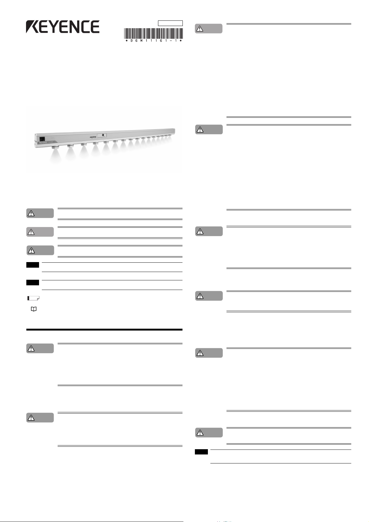
Ultra High-speed Sheath Sensing Ionizer
SJ-HA Series
SJ-H036A/060A/084A/108A/132A/156A/180A/204A/228A/252A/300A
Instruction Manual
Read this instruction manual bef ore using the product in order to achieve maximum per formance.
Keep this instruction manual in a safe plac e after reading it so that it can be used at any time.
Warning
• To avoid the risk of electric shock and ensure proper static elimination, be sure to completely ground the SJ-HA Series' 10-pin I/O cable.
• To avoid the risk of electric shock or product malfunctions, prevent water, oil, or flammable
solvent from splashing onto the SJ-HA Series.
• To avoid the risk of electric shock or product malfunctions, keep fingers and metallic
objects such as tools or wires away from the SJ-HA Series during operation.
• When the SJ-HA Series is used in an enclosed space, the generated ozone may become
harmful.
Make sure that there is adequate ventilation when using the SJ-HA Series in an enclosed
space.
• Do not use the SJ-HA Series in a location in which the temperature changes suddenly, or
where condensation occurs. This may lead to an accident or product breakdown.
• To avoid the risk of electric shock, do not operate the SJ-HA Series with wet hands.
• To avoid the risk of electric shock or product malfunctions, be sure to turn the power off
during maintenance of the SJ-HA Series.
• To avoid the risk of injury, do not touch the electrode probes directly with your hands or fingers during maintenance.
• If any abnormality is observed in the SJ-HA Series, immediately turn off the power and
contact the nearest KEYENCE office. Do not try to repair the SJ-HA Series by yourself.
This may cause electric shock or product malfunctions.
■ Symbols
The following symbols alert you to important messages. Be sure to read these messages carefully.
Danger
Warning
Caution
Important
NOTE
Reference
Provides reference pages.
Failure to follow instructions may lead to death or serious injury.
Failure to follow instructions may lead to injury.
Failure to follow instructions may lead to product damage (product malfunctions, etc.).
Provides important precautions and restrictions on proper operation.
Provides additional information on proper operation.
Provides useful information on proper operation.
Caution
• Do not touch the SJ-HA Series' electrode probes with hard objects such as tools. If the
electrode probes are damaged, the SJ-HA Series does not operate properly, resulting in
product malfunctions.
• Operate the control panel of the SJ-HA Series with the flat-blade screwdriver provided
with the product.
• When mounting the SJ-HA Series, use the provided End units (L/R) and Auxiliary Support
Part, otherwise product malfunctions may result.
• When the SJ-HA Series is used over a long time, dust accumulates on the electrode
probes. Clean the electrode probes when the alarm indicator flashes. If you continue to
use the SJ-HA Series with dust accumulating on the electrode probes, the SJ-HA Series
will not operate properly, resulting in product malfunctions. Regular cleaning (about every
2 weeks) is recommended.
•
Do not drop the SJ-HA Series or subject it to a strong impact. This may cause product malfunctions.
• Do not use the SJ-HA Series for any purpose other than eliminating static electricity.
• When the SJ-HA Series is used in combination with other instruments, functions and
performance maybe degraded, depending on operating conditions and the surrounding
environment.
■ Precautions for power supply
Caution
• Use a DC power supply at a rated supply voltage of 24 to 36 V.
• Noise conveyed through the power supply line may cause the SJ-HA Series to malfunction. Be sure to use a stabilized DC power supply with an insulated transformer.
• When using a commercially available switching regulator, be sure to completely ground
switching regulator's frame ground terminal.
• Do not connect a number of power supplies to a single SJ-HA unit or more than one SJHA unit connected together, otherwise the power supplies will be short-circuited and product malfunctions may result.
■ Precautions for grounding
The 10-pin I/O cable for the SJ-HA Series is provided with a ground wire.
Caution
• For proper static elimination, be sure to completely ground the SJ-HA Series' grounding
cable.
• The grounding cable must be grounded at a resistance not exceeding 100 Ω.
Safety Precautions
■ General precautions
Danger
■ Warnings and cautions specific to the SJ-HA Series
The SJ-HA Series is a high-voltage device that is not designed to be explosion proof. Before using
the SJ-HA Series, be sure to read the following warnings and precautions carefully.
Danger
• You must verify that the SJ-HA Series are operating correctly in terms of functionality and
performance before the start and the operation of the SJ-HA series.
• We recommend that you take substantial safety measures to avoid any damage in the
event of a problem occurring.
• KEYENCE never warrant the function or performance of the SJ-HA Series if it is used in a
manner that differs from the SJ-HA Series specifications contained in this instruction manual or if the SJ-HA Series are modified by yourself.
• Do not use the SJ-HA Series for the purpose of protecting the human body.
• Filling a closed space with nitrogen will reduce the oxygen levels in the air to dangerous
levels.
Make sure that there is adequate ventilation when using the SJ-HA Series in an enclosed
space.
• Do not use the SJ-HA Series in the presence of flammable or explosive gases or elements.
■ Warning labels on SJ-HA Series
For safety reasons, the warning labels are attached to the SJ-HA Series. Read each label carefully
and follow the instructions on the labels.
■ Locations
Caution
To prevent product malfunctions, avoid installing the SJ-HA Series in the following locations.
• Locations in which the SJ-HA Series may be directly subjected to vibration or impact.
• Locations in which the ambient temperature drops below 0°C or exceeds + 40°C.
• Locations in which the relative humidity drops below 35% or exceeds 85%, or where
condensation occurs.
• Locations in which the temperature changes suddenly.
• Locations in which the SJ-HA Series is exposed to a direct breeze from an air conditioner.
• Locations in which there are volatile, flammable substances or corrosive gas.
• Locations exposed to dust, salt, metal particles, or greasy fumes.
• Locations in which water, oil or chemicals may splash onto the SJ-HA Series.
• Locations in which a strong magnetic or electric field is generated.
• Locations where the altitude exceeds 2000 m.
• Outdoors
■ Other precautions
Caution
NOTE
• Follow the warning instructions and cautions specified in this instruction manual.
• If the unit is turned off while setting, the settings may be damaged.
Before using the unit, wait approx. 20 minutes after the unit is turned on. Otherwise, the ion
balance may not be stabilized.
1
Page 2
Precautions for CSA Certificate
Part Names
The SJ-HA Series complies with the following CSA and UL standards, and has been certified by CSA.
CAN/CSA-C22.2 No.61010-1
Safety Requirements for Electrical Equipment for Measurement, Control, and Laboratory Use
UL61010-1
Safety Requirements for Electrical Equipment for Measurement, Control, and Laboratory Use
<Precautions>
• When selecting a power supply for use with the SJ-HA Series, always use a CSA/UL-listed power
supply that either provides Class 2 output as defined in the Canadian Electrical Code/National
Electrical Code, or that has been evaluated as a Limited Power Source as defined in CAN/
CSA-C22.2 No. 60950-1/UL60950-1.
• Always establish a proper ground connections when installing the SJ-HA Series.
• Make sure to use only the connection cables provided by KEYENCE to set the SJ-HA Series units
by connecting to one another or to connect to their power supplies.
• Install the SJ-HA Series in accordance with the installation and wiring instructions described in this
instruction manual. Never operate the SJ-HA Series with the ratings that does not conform to the
specifications described in this instruction manual.
Precautions for CE Marking
The SJ-HA Series complies with the following EU Directives and EN standards.
<Precautions>
• Be sure to completely ground the SJ-HA Series' ground terminal when installing the SJ-HA Series.
• Overvoltage Category (Installation Category): I
• Pollution Degree: 2
• When selecting a power supply for use with the SJ-HA Series, always use a power supply that has
been certified by a EU Notified Body (as a Limited Power Source as defined in EN60950).
• Make sure to use only the connection cables provided by KEYENCE to set the SJ-HA Series units
by connecting to one another or to connect to their power supplies.
• Install the SJ-HA Series in accordance with the installation and wiring instructions described in this
instruction manual.Never operate the SJ-HA Series with the ratings that does not conform to the
specifications described in this instruction manual.
EU Directives
• EMC Directives (2004/108/EC)
• Low-voltage Directive (2006/95/EC)
EN Standards
• EN61326-1 Class A
• EN61010-1
This section lists the part names of the SJ-HA Series. For details about the operation keys and indicators on the controller's front panel, see "Names and functions of operation keys, switches, and indicators".
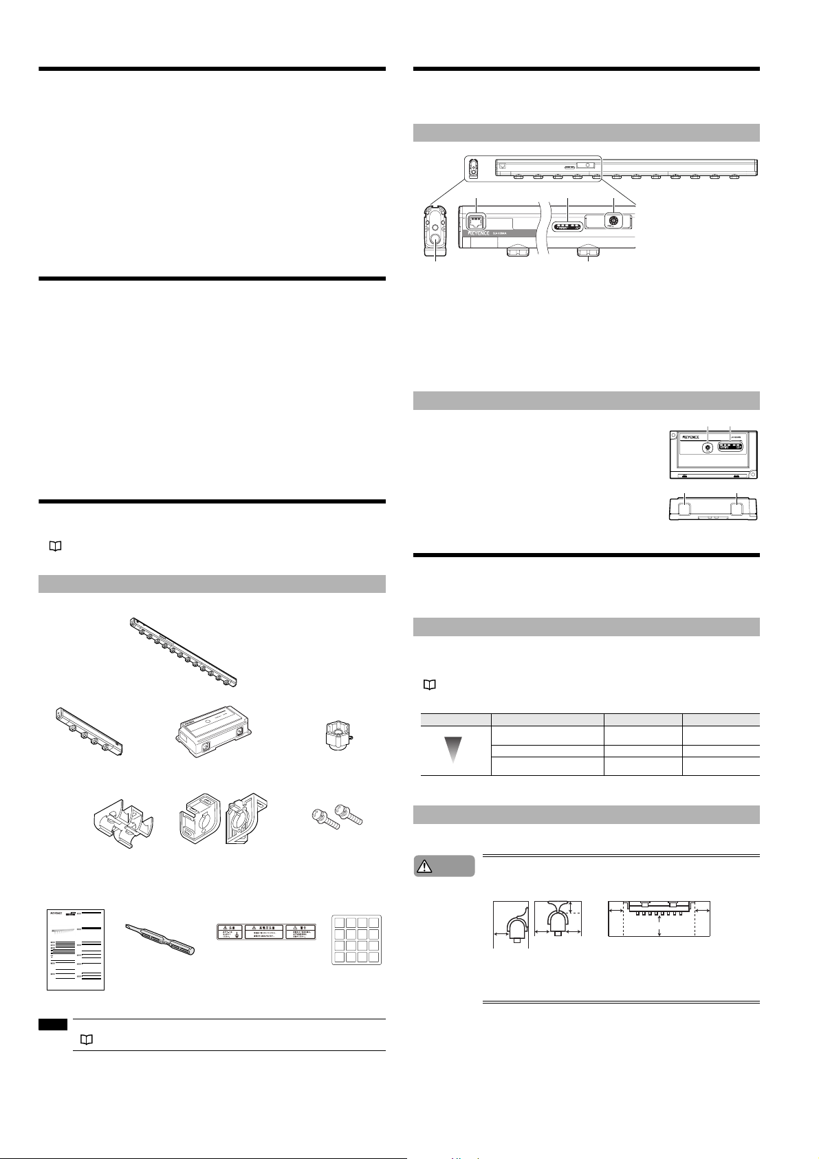
Static elimination bar (Control panel)
213
5
1. Setting block (Not provided on SJ-H036A)
2. Indicator block (Not provided on SJ-H036A)
3. Cable connector
4. Electrode probe
5. Air supply opening (Two on SJ-H036A/060A/084A/108A/132A/156A/180A/204A, and three on
SJ-H228A/252A/300A)
* The figure is for the SJ-H084A/108A/132A/156A/180A/204A/228A/252A/300A.
The position of Ion monitor of SJ-H060A is different from other models.
SJ-H036A does not have 1 and 2.
4
Control panel (SJ-H036A)
1.
Setting block
2. Indicator block
3. I/O Cable connector
4. Cable connector
21
Checking the Package Contents
The package of SJ-HA Series includes the following items. Ensure that these items are included in
your package before using the Unit. Extension cables and electrode probes for replacement are
available as options.
See “List of Optional Accessories” (page 8)
Contents
SJ-H060A/084A/108A/132A/156A/180A/204A/228A/252A/300A Controller-built-in Static Eliminator
SJ-H036A Static Elimination Bar
Auxiliary Support Part
SJ-H036A : 0
SJ-H060A : 0
SJ-H084A : 0
SJ-H108A : 0
SJ-H132A : 1
SJ-H156A : 1
SJ-H180A : 1
SJ-H204A : 1
SJ-H228A : 2
SJ-H252A : 2
SJ-H300A : 2
Instruction Manual Flat-blade screwdriver
96M11161
•To avoid the risk of electric shock and ensure proper static elimination, be sure to com-
Warning
pletely ground the SJ-HA Series' 10-pin I/O cable.
•To avoid the risk of electric shock or product malfunctions, prevent water, oil, or flammable
solvent from splashing onto the SJ-HA Series.
•To avoid the risk of electric shock or product malfunctions, keep fingers and metallic
Ultra High-speed Sheath Sensing Ionizer
objects such as tools or wires away from the SJ-HA Series during operation.
•When the SJ-HA Series is used in an enclosed space, the generated ozone may become
harmful.
Make sure that there is adequate ventilation when using the SJ-HA Series in an enclosed
SJ-HA Series
space.
•Do not use the SJ-HA Series in a location in which the temperature changes suddenly, or
SJ-H036A/060A/084A/108A/132A/156A/180A/204A/228A/252A/300A
where condensation occurs. This may lead to an accident or product breakdown.
•To avoid the risk of electric shock, do not operate the SJ-HA Series with wet hands.
uct malfunctions, be sure to turn the power off
•To avoid the risk of electric shock or prod
Instruction Manual
during maintenance of the SJ-HA Series.
•To avoid the risk of injury, do not touch the electrode probes directly with your hands or fin-
Read this instruction manual before using the product in order to achieve maximum performance.
gers during maintenance.
Keep this instruction manual in a safe place after reading it so that it can be used at any time.
•If any abnormality is observed in the SJ-HA Series, immediately turn off the power and
contact the nearest KEYENCE office. Do not try to repair the SJ-HA Series by yourself.
This may cause electric shock or product malfunctions.
•Do not touch the SJ-HA Series' electrode probes with hard objects such as tools. If the
Caution
electrode probes are damaged, the SJ-HA Series does not operate properly, resulting in
product malfunctions.
•Operate the control panel of the SJ-HA Series with the flat-blade screwdriver provided
with the product.
•When mounting the SJ-HA Series, use the provided End units (L/R) and Auxiliary Support
Part, otherwise product malfunctions may result.
•When the SJ-HA Series is used over a long time, dust accumulates on the electrode
probes. Clean the electrode probes when the alarm indicator flashes. If you continue to
use the SJ-HA Series with dust accumulating on the electrode probes, the SJ-HA Series
lting in product malfunctions. Regular cleaning (about every
will not operate properly, resu
2 weeks) is recommended.
•
Do not drop the SJ-HA Series or subject it to a strong impact. This may cause product malfunctions.
•Do not use the SJ-HA Series for any purpose other than eliminating static electricity.
■Symbols
•When the SJ-HA Series is used in combination with other instruments, functions and
The following symbols alert you to important messages. Be sure to read these messages carefully.
performance maybe degraded, depending on operating conditions and the surrounding
environment.
Failure to follow instructions may lead to death or serious injury.
Danger
■Precautions for power supply
•Use a DC power supply at a rated supply voltage of 24 to 36 V.
Caution
Failure to follow instructions may lead to injury.
Warning
•Noise conveyed through the power supply line may cause the SJ-HA Series to malfunc-
tion. Be sure to use a stabilized DC power supply with an insulated transformer.
•When using a commercially available switching regulator, be sure to completely ground
switching regulator's frame ground terminal.
Failure to follow instructions may lead to product damage (product malfunctions, etc.).
Caution
•Do not connect a number of power supplies to a single SJ-HA unit or more than one SJ-
HA unit connected together, otherwise the power supplies will be short-circuited and product malfunctions may result.
Important
Provides important precautions and restrictions on proper operation.
■Precautions for grounding
NOTE
The 10-pin I/O cable for the SJ-HA Series is provided with a ground wire.
Provides additional information on proper operation.
•For proper static elimination, be sure to completely ground the SJ-HA Series' grounding
Caution
Provides useful information on proper operation.
Reference
cable.
•The grounding cable must be grounded at a resistance not exceeding 100 :.
Provides reference pages.
■Warning labels on SJ-HA Series
Safety Precautions
For safety reasons, the warning labels are attached to the SJ-HA Series. Read each label carefully
and follow the instructions on the labels.
■General precautions
■Locations
•You must verify that the SJ-HA Series are operating correctly in terms of functionality and
Danger
performance before the start and the operation of the SJ-HA series.
To prevent product malfunctions, avoid installing the SJ-HA Series in the following locations.
Caution
•Locations in which the SJ-HA Series may be directly subjected to vibration or impact.
•We recommend that you take substantial safety measures to avoid any damage in the
•Locations in which the ambient temperature drops below 0qC or exceeds + 40qC.
event of a problem occurring.
•Locations in which the relative humidity drops below 35% or exceeds 85%, or where
•KEYENCE never warrant the function or performance of the SJ-HA Series if it is used in a
condensation occurs.
manner that differs from the SJ-HA Series specifications contained in this instruction man-
•Locations in which the temperature changes suddenly.
ual or if the SJ-HA Series are modified by yourself.
•Locations in which the SJ-HA Series is exposed to a direct breeze from an air conditioner.
•Do not use the SJ-HA Series for the purpose of protecting the human body.
•Locations in which there are volatile, flammable substances or corrosive gas.
•Locations exposed to dust, salt, metal particles, or greasy fumes.
•Locations in which water, oil or chemicals may splash onto the SJ-HA Series.
■Warnings and cautions specific to the SJ-HA Series
•Locations in which a strong magnetic or electric field is generated.
The SJ-HA Series is a high-voltage device that is not designed to be explosion proof. Before using
•Locations where the altitude exceeds 2000 m.
the SJ-HA Series, be sure to read the following warnings and precautions carefully.
utdoors
•O
•Filling a closed space with nitrogen will reduce the oxygen levels in the air to dangerous
Danger
■Other precautions
levels.
Make sure that there is adequate ventilation when using the SJ-HA Series in an enclosed
space.
•Follow the warning instructions and cautions specified in this instruction manual.
Caution
•Do not use the SJ-HA Series in the presence of flammable or explosive gases or ele-
•The SJ-HA Series uses an EEPROM. Do not turn off the unit while settings are made in
ments.
the SJ-HA Series.
1
SJ-H036A Controller
End Units (L/R)
The CAUTION/WARNING labels in
Japanese, German, French, Italian,
*1
and Chinese
*1 Use these language warning labels and ID number seals as needed.
NOTE
Prepare the 10pin I/O cable (SJ-CU) to use the SJ-HA Series.
See “Cables” (page 3).
Electrode probe
replacement kit
End Unit Securing Screws: 2
ID number seal
0 1 2 3
4 5 6 7
8 9 10 11
12 13 14 15
Installation and Connection
This section explains how to set up and install the SJ-HA Series.
Before installation, carefully consider the operating conditions such as the distance be tween the static
elimination bar and the target, or the time required for the elim ination of the target's static charge.
Static elimination ability
■ Static elimination speed and operating distance
The SJ-HA Series offers a variety of frequency settings to enable flexible static elimination
according to the location and application.
See “Frequency setting” (page 4).
Static elmination speed
High-speed
Low-speed
Precautions for installation
■ Installation location
Caution
*1
Refer to the following illustration to install the SJ-HA Series.
• Provide enough space between the static elimination bar and surrounding walls as shown
in the figures below.
• When mounting the SJ-HA Series, use the provided end unit and auxiliary support part,
otherwise an accident or malfunction may result.
• Be sure that the cable stays more than 10 mm away from the SJ-HA Series, otherwise an
accident or malfunction may result.
Location Operating distance (mm)
Production lines of films or sheets
(Short distance)
50-300 68, 47, 33, 22
Clean bench (Middle distance) 300-1000 10, 8, 5
On ceiling of clean room (Long distance)
1000-2000 3, 1
10 mm min.
10 mm
10 mm
min.
10 mm
min.
10 mm
min.
min.
20 mm min.
43
Recommended frequency (Hz)
10 mm
min.
2
Page 3
■ Interference
The SJ-HA Series may not operate properly if there is any conductive object close to the SJ-HA
Series or if another SJ-HA unit is installed closely together. Refer to the following illustration and isolate the SJ-HA Series from the conductive object.
150 mm
min.
150 mm min.
400 mm
min.
200 mm
min.
100 mm
min.
Face-to-face installation
200 mm
min.
If two SJ-HA units are used, refer to the following illustration and separate the static elimination bars
properly.
Side-to -side installation
150 mm
min.
■ Auxiliary support part (SJ-H132A/156A/180A/204A/228A/252A/300A)
Install the SJ-H132A/156A/180A/204A/228A/252A/300A with auxiliary support part. Auxiliary support
part prevents the static elimination bar from bending. Do not install the SJ-H132A/156A/180A/204A/
228A/252A/300A without using auxiliary support part.
2 Attach the end unit to each end of the static elimi-
nation bar.
3 Secure the SJ-HA Series with M4 screws at the
desired installation position.
When installing the SJ-H132A/156A/180A/204A/
228A/252A/300A, secure the auxiliary support
part with M4 screws as well.
NOTE
When removing the auxiliary support part, be sure to
remove it from the side along the guide rails.
Type
SJ-H036A/060A/084A/10 8A 0
SJ-H132A/156A/180A/20 4A 1
SJ-H
228A/
252A/300A 2
No. of auxiliary support parts necessary
for installation
■ Cables
The cables, including power cables and connector cables, required for the SJ-HA Series are not
included in the package. Confirm the installation location before installing and make sure to buy the
proper lengths of cables (10 pin I/O cable, 10-to-10-pin cable and 10-to-10-pin for SJ-H036A
cables).
Item Type Appearance Description
10-pin I/O cable
10-to-10-pin cable
10-to-10-pin cable
for SJ-H036A
Relay box
for SJ-HA
SJ-C2U (2m)
SJ-C5U (5m)
SJ-C10U (10m)
OP-42210 (2m)
OP-42211 (5m)
OP-42212 (10m)
SJ-C2H (2m)
SJ-C5H (5m)
SJ-C10H (10m)
OP-84296
Power cable for the SJ-HA
Series. Three types (2-, 5-,
10-m cables) are available.
(Cable color :Gray)
Cable for connecting the SJHA Series units. Three types
(2-, 5-, 10-m cables) are
available. Use this cable to
connect to the coupled Relay
Box. (Cable color :Gray)
The cable that connects the
SJ-H036A controller to the
bar. Three types (2-, 5-, 10-m
cables) are available. 10-pin
I/O cable is necessary for
supplying power.
(cable color :Black)
This is required if the cables
will extend more than 10
meters. (For use with the
10-to-10-pin cable)
Installing SJ-HA Series
■ Installing SJ-HA Series
Install the SJ-HA Series in places where a static problem occurs or may occur.
Caution
1
Mount the auxiliary suppor t parts on top of the static elimination bar or along the guide rails.
The SJ-H132A/156A/180A/204A requires a single auxiliary support part, the SJ-H228A/252A/
300A requires two auxiliary support parts. Mount them at approximately equal intervals.
• When installing the SJ-H132A/156A/180A/204A/228A/252A/300A, mount and secure the
auxiliary support parts with screws for the prevention of the static elimination bar from
bending, otherwise the static elimination bar may be broken.
See “Precautions for installation” (page 2).
• Keep a space of at least 10 mm around the static elimination bar after installation, otherwise the static elimination bar may malfunction or receive damage.
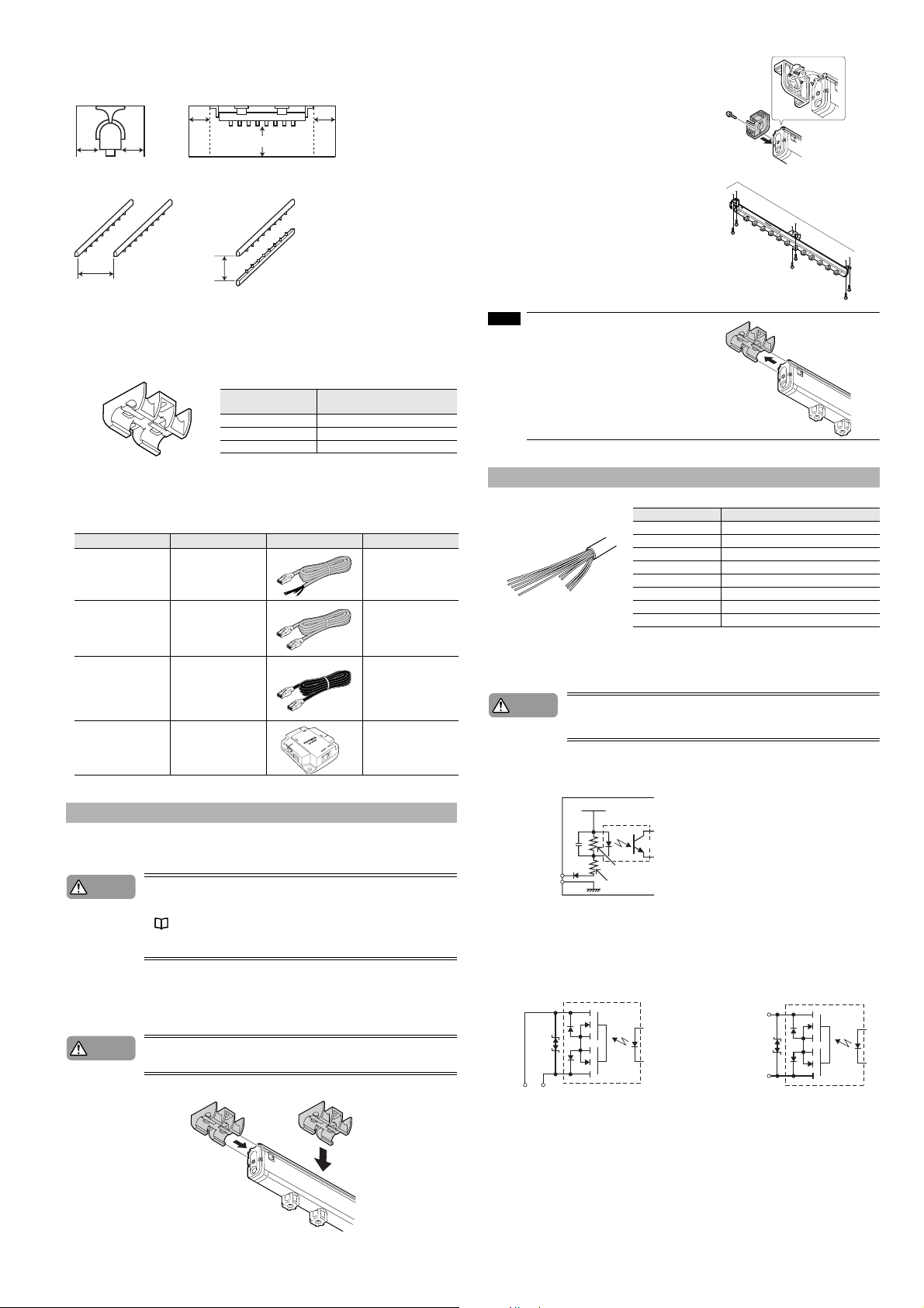
Wiring diagram (SJ-C2U/C5U/C10U 10-pin I/O cable)
Cord color Description
Caution
■ Input circuit
[Pink (Static Elimination Interrupt Input)]
INPUT (Pink)
0V (Blue)
Apply NPN open collector input to the INPUT
and 0 V terminals from non-voltage contacts
(such as relays).
■ Output circuit
Photo Relay Output
[Gray (Alarm Output)]
Do not short-circuit the output signal wire and output signal GND wire together without any
load, otherwise the internal circuit will be damaged, which may result in product
malfunctions, because the SJ-HA Series does not have any overcurrent protection circuit.
VCC (Power supply)
2.7 kΩ
2.4 kΩ
Brown (2 wires)
Blue (2 wires) Power supply GND
Pink
Orange Output signal GND
Black Ion level alarm output
White Condition alarm output
Gray Alarm output
Shield wire (thick black wire) Ground (Ground at a resistance not exceeding 100Ω.)
* The blue wire and orange wire are insulated from each other.
* There are two wires each for the brown wire and the blue wire.
Be sure to connect both of the two wires. The ends are soldered together before shipping.
DC power supply (rated voltage of 24 to 36 V)
Static elimination interrupt input
Photo Relay Output
[Black (Ion Level Alarm Output),
White (Condition Alarm Output)]
DC40 V
100 mA
OUT
Caution
Confirm that the hooks on the auxiliary support part grasp the guide rails on the static
elimination bar when installing.
•
• Mounting from the side
Mounting from the top
3
Output GND
Output GND
ALM
Page 4
Connection of power supply
■ Connecting SJ-H060A/084A/108A/132A/156A/180A/204A/228A/252A/300A to
power supply
A 10-pin I/O cable (sold separately) is required to connect the SJ-H060A/084A/108A/132A/156A/
180A/204A/228A/252A/300A to power supply.
1 See “Wiring diagram” (page 3) and connect each wire of the 10-pin I/O cable.
Caution
2 Connect the modular connector of the 10-pin I/O cable to
the SJ-H060A/084A/108A/132A/156A/180A/204A/228A/
252A/300A.
SJ-H060A/084A/108A/132A/156A/180A/204A/228A/252A/
300A have the cable connection part (10-pin).
The connector will snap when it is connected correctly.
Caution
• For proper static elimination, the ground wire must be grounded at a resistance not
exceeding 100Ω.
• Use a DC power supply with a marginal output (at least 500 mA) at a rated voltage of 24 to
36 V.
• Do not connect a number of power supplies to a single SJ-HA unit or more than one SJHA unit connected together, otherwise the power supplies will be short-circuited an accident or malfunction may result.
• Press the tab of the modular connector to disconnect the cable. Do not pull the cable without pressing the tab, otherwise the cable may be damaged.
• Keep a space of at least 10 mm around the static elimination bar after installation, otherwise the static elimination bar may malfunction or receive damage.
Static Elimination Setting
This section provides the name and functions of operation keys, switches, and indicators on the controller’s front panel. It also describes the operation procedure for the static elimination setting.
Names and functions of operation keys, switches, and indicators
The control panel of the SJ-H084A/108A/132A/156A/180A/204A/228A/252A/300A has the same layout.
The control panel of the SJ-H060A and SJ-H036A has the setting switch and display part positions
swapped.
3
2
1. FREQ switch....... Sets the frequency
2. ION MONITOR ... Displays the strength of the electric charge of the object.
3. Alarm Indicator... This flashes once per second if static elimination power is affected by situations
such as an absorption of ions by surrounding metals, which can cause instability of the setting environment (temperature, humidity, surrounding metals).
(Condition alarm) This will blink twice per second if the ion generation capability
falls below the set value due to wear or dirt on the electrode probe.
(Ion level alarm) Flashes if the quantity of ion generation is low due to the deterioration of the electrode probes or the dirt on the electrode probes. Then static
elimination will be forcibly turned OFF. (Alarm)
1
■ Connecting SJ-H036A to power supply
A 10-pin I/O cable and a 10-to-10-pin cable (both sold separately) are required to connect the
SJ-H036A to power supply.
1 See “Wiring diagram” (page 3) and connect each wire of the 10-pin I/O cable.
Caution
2 Connect the modular connector of the
10-pin I/O cable to the SJ-H036A controller.
Connect the cable to the cable connection part indicated
“GRAY” on the controller.
The connector will snap when it is connected correctly.
3 Connect the SJ-H036A controller and the static elimina-
tion bar over the 10-to-10-pin cable.
Connect the cable to the connector marked by the word
"BLACK." Then connect the cable to the static elimination bar
of the SJ-H036A.
The connector will snap when it is connected correctly.
Caution
• For proper static elimination, the ground wire must be grounded at a resistance not
exceeding 100 Ω.
• Use a DC power supply with a marginal output (at least 500 mA) at a rated voltage of 24 to
36 V.
• Do not connect a number of power supplies to a single SJ-HA unit or more than one SJHA unit connected together, otherwise the power supplies will be short-circuited an accident or malfunction may result.
• Press the tab of the modular connector to disconnect the cable. Do not pull the cable without pressing the tab, otherwise the cable may be damaged.
• Keep a space of at least 10 mm around the static elimination bar after installation, otherwise the static elimination bar may malfunction or receive damage.
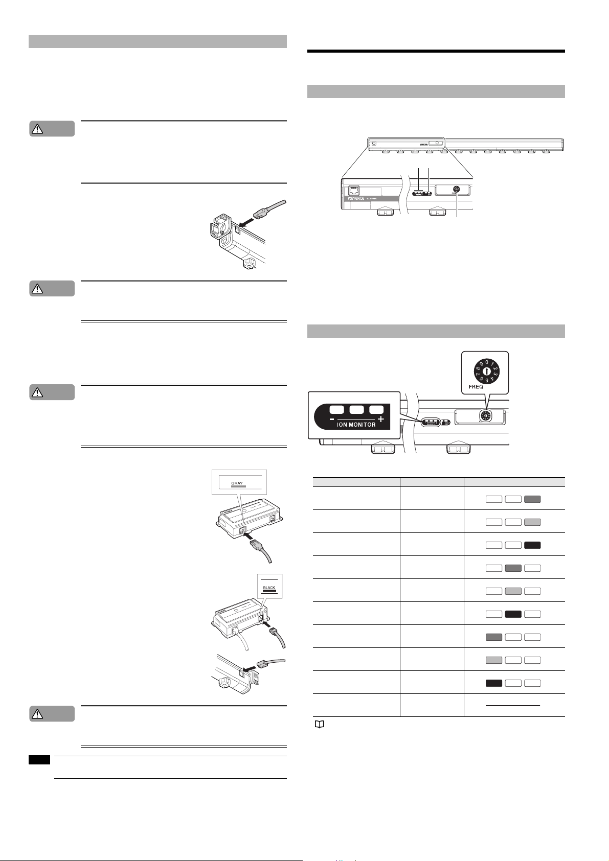
Frequency setting
A frequency is set with the FREQ switch in the SJ-HA Series.
When the frequency setting is made, the indicator for the present frequency on the ION MONITOR
will flash for approximately five seconds. Then the indicator will be turned OFF.
Frequency FREQ . switch ION MONITOR
68Hz 0
47Hz 1
33Hz 2
22Hz 3
10Hz 4
8Hz 5
5Hz 6
3Hz 7
1Hz 8
Not used 9
For frequency settings in detail, see “Static elimination ability” (page 2).
OFF OFF Green
OFF OFF Ye l lo w
OFF OFF Red
OFF Green OFF
OFF Yel lo w OFF
OFF Red OFF
Green OFF OFF
Yel lo w OFF OFF
Red OFF OFF
NOTE
The SJ-H036A static elimination bar and controller should bear the same serial number. Check that
they bear the same serial number when connecting them.
4
Page 5

Other Functions
This section describes other functions such as the display function, alarm output function, and air
purge function.
Indicators
The target's static charge and the quantity of ions generated from the static elimination bar are displayed on the ION MONITOR.
Air-purge function
Supplying clean air through the air duct on both ends of the static elimination bar will prevent the dust
accumulation on the electrode probes. The air purge widens the static elimination area and increases
the speed of static elimination as well.
* The air pressure indicates the pneumatic value at the route of the joint.
*
Please contact the nearest KEYENCE office when using the air-purge function with intermittent air supply.
Danger
Filling a closed space with nitrogen will reduce the oxygen levels in the air to dangerous
levels.
Make sure that there is adequate ventilation when using the SJ-HA Series in an enclosed
space.
■ Electric charge indicator
The ION MONITOR works as an electric charge indicator that displays the target's static charge,
polarity of the static charge, and condition of static elimination.
The plus and minus side LEDs will illuminate in response to the current charge level.
When static elimination is finished, the indicator in the middle will be illuminated. Therefore, the user
will know the process of static elimination.
ION MONITOR Condition
OFF OFF Red
OFF OFF Yellow
OFF OFF Green
OFF Green OFF
Green OFF OFF
Yel lo w OFF OFF
Red OFF OFF
Positively charged object
Negatively charged object
High
Middle
Low
Low
Middle
High
Alarm output function
■ Alarm function (ALM)
The ION/ALM/COND indicator will flash red three times per second and
an alarm signal (N.C. control signal) will be output if the internal circuit
is damaged or an abnormal electrical discharge occurs.
Then the SJ-HA Series will stop generating ions.
Alarm output will activate regardless of whether or not static elimination
is being interrupted manually or forcibly.
■ Ion level alarm function (ION)
The ION/ALM/COND indicator will flash twice per second and an alarm
signal (N.O. control signal) will be output if the quantity of ion generation is low due to the deterioration of the electrode probes or the dirt on the electrode probes. Static elimination will not be interrupted in this case.
The ion level warning can be a notice for the maintenance of the electromagnetic probes. Static elimination continues, so make sure to turn off the power when you perform maintenance on the electromagnetic probes.
■ Condition alarm function (COND)
The ION/ALM/COND indicator will flash once per second and an alarm signal (N.O. control signal)
will be output if the installation environmental conditions (e.g., the temperature, humidity, and ambient
metal) are unstable and likely to affect the performance of static elimination adversely (e.g., the
absorption of ions) caused by ambient metal objects. Static elimination will not be interrupted in this
case.
Caution
Provide clean, dry air free of organic matter at a condensation point of -25 °C and approximately 0.01
μm in mesh size.
• Check that the air pressure does not exceed 0.5 MPa, otherwise an accident or malfunction may result.
• Please contact the nearest KEYENCE office when opening and closing the air duct.
• Be sure to provide clean, dry air to the static elimination bar. If the air contains water or oil,
air leaks or electrical discharges may occur in the static elimination bar, thus resulting in
accidents or malfunctions.
• Be sure to supply air from both sides (2 locations) of the SJ-H036A/060A/084A/108A/
132A/156A/180A/204A.
• Be sure to supply air from both sides (3 locations) of the SJ-H228A/252A/300A.
■ Air supply method
As shown in the illustration below, remove the screw that block the air duct on either end of the static
elimination bar, connect a joint to the air duct, and provide air.
Caution
Recommended joint
The recommended joint is the Tube Fitting (tube diameter : φ 8 mm) manufactured by Pisco Co.
NOTE
• Be sure to limit the tightening torque to 1.2 N•m (12 kg•cm2) or less. Otherwise, an accident or product breakdown may occur.
• Be sure to supply only clean, dry air. The use of improper air may cause an accident or
product malfunctions.
• Be sure to supply air from both sides (2 locations) of the SJ-H036A/060A/084A/108A/
132A/156A/180A/204A.
• Be sure to supply air from both sides (3 locations) of the SJ-H228A/252A/300A.
SJ-H036A/060A/084A/108A/132A/156A/180A/204A
Rc1/8
R1/8
SJ-H228A/252A/300A
Rc1/8
R1/8
Tube diameter φ 8 mm : PC8-01
• Use a joint having a tube diameter of 8 mm on the SJ-HA Series.
• When providing air to more than one SJ-HA unit, check that each static elimination bar is provided with
air. If the air supply source is one, each static elimination bar may not be provided with enough air.
Rc1/8
Rc1/8
Abnormal discharge detection function
The SJ-HA Series detects abnormal electric discharge caused by the condensation on the tips of
the electrode probes or conductive objects that may come close to the electrode probes, thus
interrupting the generation of ions and prevent the occurrence of trouble.
R1/8
R1/8
Elimination interruption function
For the purpose of energy saving, by short-circuiting the blue (DC GND wire) and pink (static elimination interruption input signal wire) wire terminals of the 10-pin I/O cable, only the static elimination
function will be turned OFF without turning off the SJ-HA Series.
5
Page 6

Settings for SJ-HA Units in Coupled Operation
Maintenance of Electrode Probes
Using the coupled Relay Box, more than one SJ-HA Series can be used by coupling in parallel.
Frequency setting
When using SJ-HA units in coupled operation, set a unique frequency for each SJ-HA unit individually.
Connecting SJ-HA Series units in coupled operation
Caution
NOTE
Up to seven SJ-HA units can be connected in parallel over the optional 10-to-10-pin serial cable
through the optional OP-84296 relay box.
Do not connect a number of power supplies to a single SJ-HA unit or more than one SJ-HA
unit connected together, otherwise the power supplies will be short-circuited an accident or
malfunction may result.
• A coupled installation of the SJ-HA units is possible under the following restrictive conditions.
• Up to seven SJ-HA units can be connected.
• The total extension length between the power supply an d the farthest static eliminatio n bar is within
30 m.
• When providing air to more than one SJ-HA unit, check that each static elimination bar is provided with
air. If the air supply source is one, each static elimination bar may not be provided with enough air.
10-to-10-pin cable
10-to-10-pin cable for
SJ-H036A
When the SJ-HA Series is used for a long period, the electrode probes become dirty due to the accumulation of dust.
If you continue to use the SJ-HA Series with dust accumulating on the electrode probes, the static
elimination ability may deteriorate, resulting in an accident or product breakdown. Therefore, be sure
to clean the electrode probes periodically.
Maintenance of electrode probes
Use the electrode probe cleaning kit (OP-84299) or a cotton swab when performing maintenance for
the electrical probes.
Warning
• Turn off the SJ-HA Series before the maintenance of the electrode probes.
• Do not touch the electrode probes directly with your hand or fingers, as this may cause
injury. Be extremely careful when cleaning them.
■ Cleaning the electrode probes : Electrode probe cleaning kit (OP-84299)
Soak the filter of the cleaning kit with alcohol, and place the cleaning kit on the electrode probe and
rotate it gently two or three times.
The filter on the cleaning kit will remove any dirt from the electrode probes. Replacement filters
(OP-42218) are also available.
* For information on how to replace the filter, see "Electrode Probe Cleaning Kit Instruction Manual".
■ Clean the electrode probe : Cotton bud
Clean the electrode probe with a cotton bud moistened with alcohol.
Relay box
DC power supply at a rated
voltage of 24 to 36 V.
10-pin I/O cable
OP-84296 relay box
Using the OP-84296 relay box allows the SJ-HA Series to be connected in parallel.
Use the relay box (OP-84296) as well when extending the cable.
• Set the terminator switch to "2" if the SJ-HA Series is connected to the OUT port of the relay box.
• Set the terminator switch of the OUT port that is not connected to the SJ-HA Series to "1".
Caution
NOTE
Do not connect a number of power supplies to a single SJ-HA unit or more than one SJ-HA
unit connected together, otherwise the power supplies will be short-circuited an accident or
malfunction may result.
• A coupled installation of the SJ-HA units is possible under the following restrictive conditions.
• Up to seven SJ-HA units can be connected.
(Seven units can be connected only when using the power supply of 36 V. When using 24 V, contact
your nearest KEYENCE sales office.)
• The total extension length from the power supply to the farthest static elimination bar must be less
than 30 m.
• When providing air to more than one SJ-HA unit, check that each static elimination bar is provided with
air. If the air supply source is one, each static elimination bar may not be provided with enough air.
■ Changing the electrode probes
Place the included electrode probe replacement kit over the electrode probe and press it towards the
device while rotating it counter-clockwise to remove the electrode probe.
To attach an electrode probe, place the new probe in the electrode probe replacement kit, line it up
with the grooves and insert it. Press the kit towards the device and turn clockwise to secure the electrode probe.
NOTE
•
When attaching an electrode probe, line up the mar kings on the device and the markings on the electro de
probe.
Electrode probe markings
• When attaching an electrode probe, check that the O-ring is at the designated position.
Device markings
O-ring
6
Page 7

Timing Charts
Troubleshooting
This section explains the timing charts of the SJ-HA Series.
■ Control of Ion generation
Static electricity
stop input
Ion generation
state
Alarm output
ON
OFF
ON
OFF
ON
OFF
● Static elimination ON/OFF Indicator
Normal operation
Static charge or ion quantity
Forced static elimination ON
Flashing green
■ Input response
ON
Static elimination
interruption input
OFF
(SJ-HA Series)
Yes
High voltage
output
No
50 ms max.
■ Ion level alarm output timing chart
ON
Power supply
OFF
ON
Static elimination
interruption input
OFF
Yes
Ion generation
No
ON
Alarm output
(N.C.)
OFF
Flashing
ION/ALM/COND
indicator
OFF
ION LEVEL
ON
alarm output
OFF
(N.O.)
■ Condition alarm output timing chart
ON
Power supply
OFF
ON
Static elimination
interruption input
OFF
Yes
Ion generation
No
ON
Alarm output
(N.C.)
OFF
Flashing
ION/ALM/COND
indicator
OFF
ON
Condition alarm
output (N.O.)
OFF
■ Alarm output timing chart
ON
Power supply
OFF
Flashing
ION/ALM/COND
indicator
OFF
ON
Static elimination
interruption input
OFF
Yes
Ion generation
No
ON
Alarm output
(N.C.)
OFF
Normal static elimination OFF
Flashing red
Forced static elimination OFF
Flashing red
After the ION LEVEL alarm is once
displayed, the SJ-HA Series will not
return to the previous state unless any
of the following items is performed.
1. Static elimination is interrupted.
2. Setting changes are made.
The SJ-HA Series is turned off and on.
3.
When the cause of the condition
alarm output is remedied after the
condition alarm is displayed once, the
SJ-HA Series will return to normal
mode.
Once the alarm is indicated, the
unit returns to the previous state
by turning the power on again.
Refer to the following list for troubleshooting and remedies before sending out the unit for repairs.
Problem Inspection Remedy
No ION MONITOR indicators are
working.
No static elimination is performed.
Static elimination is no t performed
properly.
Ion level (ION LEVEL) alar m is
illuminated and output frequently.
The condition (COND) alarm is
illuminated and output frequently.
The alarm (ALM) indicator is
illuminated.
Control output is not outpu t correctly. Check that the cable is wired correctly.
Static elimination interrupt input is not
input properly.
Cannot understand the meaning of the
indicators
A distance extension of 10 m or more
is required.
Check that the power suppl y cable is
connected correctly.
Check that the power supply is within
the rated range.
Check that the electrode probes are
not worn out or dirty.
Check that static elimination is not
interrupted.
Check if the abnormal di scharge
detection function is working. (Check if
the alarm is output)
Check that the ground is connected.
Check that the correct frequency
setting is selected.
Check that there is no conductive
object or another Static Eliminator Unit
close to the SJ-HA Series.
Check that the ground is connected.
Check that the electrode probes are
not worn out or dirty.
Check that there is no conductive
object or another Static Eliminator Unit
close to the SJ-HA Series.
Check that there is no conductive
object within 10 mm of the SJ-HA
Series.
Check that the SJ-C*H is connected.
Check that the cable is wired correctly.
-
-
Connect the power suppl y cable
correctly.
Use power supply within the rated
range.
Carry out maintenance work on the
electrode probes or replace them.
Cancel the static electricity stop input
of the SJ-HA Series (Open the input
terminal.).
Eliminate conductive objects within 20
mm of the electrode probe and turn on
the SJ-HA Series again.
Confirm that the ground is properly
connected.
Select the optimal frequency setting
according to the operating distance.
Keep the SJ-HA Series away from the
conductive object or the Static
Eliminator Unit.
Confirm that the ground is properly
connected.
Carry out maintenance work on the
electrode probes or replace them.
Keep the SJ-HA Series away from the
conductive object or the Static
Eliminator Unit.
Eliminate the conductive object within
10 mm of the SJ-HA Series and turn
the SJ-HA Series OFF and ON. The
abnormal discharge detection function
may have been turned ON.
The modular jack may not be inserted
properly or the cable may be
disconnected. Connect the modular
jack correctly and turn the SJ-HA
Series OFF and ON.
Check the output circuit and make sure
that the wiring is correct.
Check the input circuit and make sure
that the wiring is correct.
See “Indicator Specifications”
(page 8).
Purchase the Extension Ca ble and
Relay Connector.
Warnings and Remedies
This section explains each type of warning, as well as the most common causes and best remedies
for each issue.
Alarm
Ion level warning
Condition warning
Warni ng Major causes Remedy
Irregular discharge from the e nd of a
probe
Ground not connected
Internal circuit damage Contact your nearest sales office.
Dirt on the electrode probes
Electrode probe wear
Ground not connected
Influence from a grounding conductor
near the static elimination device
Ground not connected
Turn the power off and remove any
conductive objects from the area
around the static elimination bar.
Confirm that the ground is properly
connected.
Turn the power OFF and clean the
electrode probe. If the ion level
warning persists after cleaning,
confirm the surroundi ngs of the
electrode probe.
Turn the power OFF and replace the
electrode probe
Confirm that the ground is properly
connected.
The warning may flash when a
grounding conductor such as a metal
object is close enough to interfere with
the static elimination device. Remove
any grounding conductors near the
static elimination devi ce.
See “Interference” (p age 3).
Confirm that the ground is properly
connected.
7
Page 8

Indicator Specifications
■
Indicator specifications during setting change, checking, and while in operation
Indicator Lighting specifications Description
One of the "ION MONITOR" lights is illuminated
ION MONITOR
ION/ALM/COND
ION/ALM/COND, ION
MONITOR
One of the "ION MONITOR" lights flashes.
The ION MONITOR indicator in the middle
flashes red.
The ION/ALM/COND flashes once per second
The ION/ALM/COND indicator flashes twice per
second.
The ION/ALM/COND indicator and the all ION
MONITOR indicator flash red.
Charge level display
Displays the target's static charge. When the
leftmost (or rightmost) indicator is illuminated, it
means that the target's negative (or positive)
static charge is very high. The indicator
illuminated changes according to the quantity
of the target's static charge.
See “Indicators” (page 5).
Frequency setting
When the frequency is set, the indicator
corresponding to the set freq uency will flashes
for approximately five seconds.
See “Frequency setting” (page 4).
Normal static elimination interruption
The indicator will flash red when static
elimination is interrupted by short-circuiting the
blue and pink wires of the 10-pin I/O cable.
Condition warning
The indicator flashes if the ion balance is bad
due to the influence of the installation
environment.
Flashes Green :Sensitivity low
When the alarm level is changed to another
level, the indicator will flash slowly for approx.
five seconds.
When the condition war ning and the ion level
warning occur at the same time, the "ION/ALM/
COND" indicator flashes first for the ion level
warning.
Ion level warning
The indicator flashes when the quantity of ion
generation drops below the set value.
Flashes Green :Sensitivity low
When the alarm level is changed to another
level, the indicator will flash slowly for approx.
five seconds.
When the condition war ning and the ion level
warning occur at the same time, the "ION/ALM/
COND" indicator flashes first for the ion level
warning.
Alarm
When an abnormal electric discharge occurs or
the internal circuit is damaged, the ION/ALM/
COND indicator will flash three times per
second and the ION MONITOR indicators will
flash red slowly.
List of Optional Accessories
Item Typ e Appearance Description
10-pin I/O cable
10 pin-10 pin cable
10-to-10-pin cable for SJ-H036A
Tungsten electrode probes
(four) for SJ-HA
Connection relay box OP-84296
End unit OP-84301 Used for installing the SJ-HA Series.
Auxiliary support component OP-84300
Electrode probe cleaning kit OP-84299
Replacement filters for the
electrode cleaning kit
(10 pieces)
Electrode probe cleaning kit 2 OP-84454
Replacement filter for the
electrode probe cleaning kit 2
(10 pieces)
SJ-GL/G/V/R exchange
side supports
SJ-C2U (2m)
SJ-C5U (5m)
SJ-C10U (10m)
OP-42210 (2m)
OP-42211 (5m)
OP-42212 (10m)
SJ-C2H (2m)
SJ-C5H (5m)
SJ-C10H (10m)
OP-84293
OP-42218 Cotton filters for the cleaning kit.
OP-84455
OP-84297
Power cable for the SJ-HA Series.
Three types (2-, 5-, 10-m cables)
are available.
(Cable color: Gray)
Cable for connecting the SJ-HA
Series units. Three types (2-, 5-, 10m cables) are available. Use this
cable to connect to the coupled
Relay Box.
(Cable color: Gray)
The cable that connects the
SJ-H036A controller to the bar.
Three types (2-, 5-, 10-m cables)
are available.
(Cable color: Black)
Tungsten-made electrode probes
(Made for SJ-HA)
Used for connecting SJ-HA units
together.
Used to for installing
SJ-HA Series.
Used for maintaining the electrode
probes on the SJ-HA Series.
Used to perform maint enance on
the inside wall of the el ectrode
probe cap.
Replacement filters for the cleaning
kit 2.
Used to match the installation
dimensions of the SJ-GL/ G/V/R
Series. Also used for rotation.
SJ-GL/G/V/R exchange
central supports
Electrode probe replacement kit OP-84363
OP-84298
Used to match the installation
dimensions of the SJ-GL/ G/V/R
Series. Also used for rotation.
Used for changing the electrode
probes on the SJ-HA Series.
8
Page 9

Dimensions
(
)
)
■ Controller unit (SJ-H036A only)
71
(14.5)
130
120
2xφ5
59
(43)
(35)
33
48.2
(R24)
■ Main body
10
25
22.5
12.5
SJ-H036A
*1 90mm
*2 21mm
22
48
Rc1/8
SJ-H036A
*1 90mm
*2 21mm
(67.7)
39.5
10.5
23
9.2
23
11
2
38*
12.5 70
Type
21
SJ-H036A has no connector connection part
Only SJ-H036A has a connector connection part
*1
Electrode probes A B C D
Mount one auxiliary support bracket per meter
B
A
C
D
SJ-H036A 4 380 340 365 P60×3=180
SJ-H060A 8 600 560 585 P60×7=420
SJ-H084A 12 840 800 825 P60×11=660
SJ-H108A 16 1080 1040 1065 P60×15=900
SJ-H132A 20 1320 1280 1305 P60×19=1140
SJ-H156A 24 1560 1520 1545 P60×23=1380
SJ-H180A 28 1800 1760 1785 P60×27=1620
SJ-H204A 32 2040 2000 2025 P60×31=1860
SJ-H228A 36 2280 2240 2265 P60×35=2100
SJ-H252A 40 2520 2480 2505 P60×39=2340
SJ-H300A 48 3000 2960 2985 P60×47=2820
Common for the left side of the bar Common for the right side of the bar
39.5
22.5
*2
(R24)
(28)
45
*1 SJ-H036A only has the left socket.
*2 SJ-HA type only has the right socket.
(Except for the SJ-H036A)
*1
(R24)
48
Rc1/8
45
(SJ-H228A and longer models)
39.5
22.5
*
Rc1/8
* Not provided for the SJ-H204A or shorter models.
When a rotating mounting bracket is attached
61.3
(119)
29 18
Type
48.5
9.2
A
B
C
21
SJ-H036A has no connector connection
part
23
30
Only SJ-H036A type has a connector
connection part
*2
38
*1
70
A B C
SJ-H036A 451 432 400
SJ-H060A 671 652 620
SJ-H084A 911 892 860
SJ-H108A 1151 1132 1100
SJ-H132A 1391 1372 1340
SJ-H156A 1631 1612 1580
SJ-H180A 1871 1852 1820
SJ-H204A 2111 2092 2060
SJ-H228A 2351 2332 2300
SJ-H252A 2591 2572 2540
SJ-H300A 3071 3052 3020
Common for the left side of the bar
27.5
(79.5)
99.5
*2
(R24)
45
*1 SJ-H036A only has the left socket.
*2 SJ-HA type only has the right socket.
(Except for the SJ-H036A)
*1
(R24)
Rc1/8
45
Common for the right side of the bar
(SJ-H228A and longer models)
*
99.5 27.5
* Not provided for the SJ-H204A or shorter models.
73.5
Rc1/8
Rc1/8
■ End unit L ■End unit R
10.5
20
12.5
39.5
22.5
5
12.5
20
10.5
39.5 35
48.5
(*)Ellipse hole
5
6
4.4
4-Ellipse hole(*)
23
12.5
23
11
12.5
23
4-Ellipse hole(*)
23
11
39.5
22.5
5
5
(*)Ellipse hole
4.4
39.535
6
■ Auxiliary support
(Rear)
5
2-Ellipse hole(*2)
28
(Thickness: 5 mm)
34
45
2-Ellipse hole(*1)
Thickness: 5 mm
5
22.5
(*1)Ellipse hole (*2)Ellipse hole
2.6
1.4
4.4
4.4
5
■ Support part for converting to SJ-GL/G/V/R (side)
68.6
27.5
4
91 86
o
(*)Ellipse hole
5.2
8
29
4-Ellipse hole(*
16 30
18
(When rotated by 90
(40)
)
63.5
■ Support part for converting to SJ-GL/G/V/R (intermediate)
3
2-Ellipse hole(*)
(40)
40
(When rotated by 90o)
27.5
(*)Ellipse hole
4
27.5
64.7
5.4
78 62
■ Relay box (OP-84296)
70
56
(9)
2-φ5
48
48
(9)
(14)
(R24)
48
47
58
(5.5)
48
(14)
25.5
4.5
9
Page 10

Static Elimination Function List
m
]
]
■ Operating area and operation time
This section shows typical examples of the time necessary for static elimination, and the relationship of the installation distance between the target and the static elimination bar.
Operating area and time (33 Hz) Operating area and time (10 Hz) Operating area and time (1 Hz) Operating area and time (at air MAX )
150300450
50100150
50 100 150mm
150300450
150 300 450mm
150300450
600 150 300 450 600mm
600 150 300 450 600mm
50
0.4sec
0.6sec
0.8sec
1.0sec
Measurement conditions:
The time required to eliminate the static charge of
the target from ±1000 V to ±100 V is measured.
The 150
SJ-H108A is used.
No downflow
1.2sec
×150mm plate monitor (20 pF) is used.
100
150m
Measurement conditions:
The time required to eliminate the static charge of
the target from ±1000 V to ±100 V is measured.
The 150
SJ-H108A is used.
Under the downward air flow of 0.3 m/sec.
5sec
10sec
15sec
30sec
×150 mm plate monitor (20 pF) is used.
■ Relationship between air pressure and air flow with different bar lengths
The relationship between air pressure and air flow varies depending on the length of the static elimination bar.
Refer to the typical example on the right to select the appropriate air supply device (compressor) that
will supply sufficient air flow.
1200
1000
800
600
400
Supplied flow[N /min]
200
0
0.0 0.1 0.2 0.3 0.4 0.5
Air pressure[MPa
SJ-H036A
SJ-H060A
SJ-H084A
SJ-H108A
SJ-H132A
SJ-H156A
SJ-H180A
SJ-H204A
SJ-H228A
SJ-H252A
SJ-H300A
300
600
900mm
30sec
Measurement conditions:
The time required to eliminate the static charge of
the target ±1000 V to ±100 V is measured.
The 150
×150 mm plate monitor (20 pF) is used.
SJ-H108A is used.
Under the downward air flow of 0.3 m/sec.
■ Relationship between operating time and operating distance with different air
pressure
The relationship between operating time and operating distance varies depending on the air pressure.
Refer to the typical example on the right to select the appropriate air pressure.
10
8
6
4
Static elimination time[sec]
2
0
0 50 100 150 200 250 300
Measurement conditions:
The time required to eliminate the static charge of
the target from ±1000 V to ±100 V is measured.
The 150 x 150 mm plate monitor (20 pF) is used.
SJ-H108A is used.
No downflow
■ Relationships between installation speed and static elimination speed due to frequency settings
This displays the relationship between frequency settings and static elimination speed and installation distance
25
20
33Hz
22Hz
4sec
6sec
10sec
20sec
Operating distance[mm]
300
600
900
1200
1500mm
300
0.5sec
1sec
2sec
3sec
Measurement conditions:
The time required to eliminate the static charge of
the target from ±1000 V to ±100 V is measured.
The 150
×150mm plate monitor (20 pF) is used.
SJ-H108A is used.
No downflow
0MPa
0.002MPa
0.01MPa
0.2MPa
0.5MPa
600
900
1200
1500mm
15
10
Static elimination time[sec]
5
0
0 50 100 150 200 250 300
30
25
20
15
10
Static elimination time[sec]
5
0
0 200 400 600 800 1000 1200 1400 1600
Operating distance[mm]
Measurement conditions:
The time required to eliminate the static charge of
the target from ±1000 V to ±100 V is measured. The
150 x 150mm plate monitor (20 pF) is used.
SJ-H108A is used.
No downflow
Operating distance[mm
Measurement conditions:
The time required to eliminate the static charge of
the target from ±1000 V to ±100 V is measured. The
150 x 150mm plate monitor (20 pF) is used.
SJ-H108A is used.
Under the downward air flow of 0.3 m/sec.
10Hz
5Hz
3Hz
1Hz
10
Page 11

Specifications
Series name SJ-HA Series
Ion generating method Corona discharge
Structure Shock-less resistance coupled
Voltage application method/Applied voltage Pulse AC method /± 7000 V
Ion balance control method Dual I.C.C.
Ion balance
Operating distance 50 to 2000 mm
Control input NPN open collector or non-voltage relay signal
Control output NPN photo relay with 100 mA max. (at 40 V max.)
Rating
Major functions Condition (COND) warning, ion level (ION LEVEL) warning, alarm (ALM) output
Air purge connectio n port Rc 1/8
Air purge supply pressure 0.5 MPa max.
Material
Environment
Item Specifications
*1
Power supply 24-36 VDC ± 10 %
Current consumption 500 mA (at 24VDC), 350 mA or less (at 36 VDC)
Overvoltage category I
Pollution degree 2
Electrode probe Tun gs te n
Main body ABS, PC
Ambient temperature 0 to +40 °C
Relative humidity 35 to 85 % RH, No condensation
± 30 V
*2
*1 The value is measured under the following condition.
Operating distance 300 mm (22 Hz) 600 mm (10 Hz) 1500 mm (1 Hz)
Ambient temperature 0 to +40 °C
Relative humidity 35 to 65 % RH
* Under the downward air flow of 0.3 m/sec.
*2 Please contact the nearest KEYENCE office when using the air-purge function with intermittent air supply
■ Effective length, total length, weight
Model SJ-H036A SJ-H060A SJ-H084A SJ-H108A SJ-H132A SJ-H156A SJ-H180A SJ-H204A SJ-H228A SJ-H252A SJ-H300A
Effective length
Total length
Weight (u nit:g)
*3 The effective length represents the operating area at an operating distance of 50 mm.
*4 The total length represents the length of the model with a end unit attached.
Item Specifications
*3
*4
(unit:mm) 360 600 840 1080 1320 1560 1800 2040 2280 2520 3000
(unit:mm) 380 600 840 1080 1320 1560 1800 2040 2280 2520 3000
Static elimination bar :510 (500)
Controller :150
780 980 1200 1400 1550 1750 2000 2350 2700 3150
11
Page 12

WARRANTIES AND DISCLAIMERS:
(1) KEYENCE warrants the Products to be free of defects in materials and workmanship for a period of one (1)
year from the date of shipment. If any models or samples were shown to Buyer, such models or samples were
used merely to illustrate the general type and quality of the Products and not to represent that the Products
would necessarily conform to said models or samples. Any Products found to be defective must be shipped to
KEYENCE with all shipping costs paid by Buyer or offered to KEYENCE for inspection and examination.
Upon examination by KEYENCE, KEYENCE, at its sole option, will refund the purchase price of, or repair or
replace at no charge any Products found to be defective.
This warranty does not apply to any defects resulting from any action of Buyer, including but not limited to
improper installation, improper interfacing, improper repair, unauthorized modification, misapplication and
mishandling, such as exposure to excessive current, heat, coldness, moisture, vibration or outdoors air. Components which wear are not warranted.
(2) KEYENCE is pleased to offer suggestions on the use of its various Products. They are only suggestions, and it
is Buyer's responsibility to ascertain the fitness of the Products for Buyer’s intended use. KEYENCE will not
be responsible for any damages that may result from the use of the Products.
(3) The Products and any samples ("Products/Samples") supplied to Buyer are not to be used internally in humans,
for human transportation, as safety devices or fail-safe systems, unless their written specifications state otherwise.
Should any Products/Samples be used in such a manner or misused in any way, KEYENCE assumes no
responsibility, and additionally Buyer will indemnify KEYENCE and hold KEYENCE harmless from any liability or damage whatsoever arising out of any misuse of the Products/Samples.
(4) OTHER THAN AS STATED HEREIN, THE PRODUCTS/SAMPLES ARE PROVIDED WITH NO OTHER
WARRANTIES WHATSOEVER. ALL EXPRESS, IMPLIED, AND STATUTORY WARRANTIES,
INCLUDING, WITHOUT LIMITATION, THE WARRANTIES OF MERCHANTABILITY, FITNESS FOR
A PARTICULAR PURPOSE, AND NON-INFRINGEMENT OF PROPRIETARY RIGHTS, ARE
EXPRESSLY DISCLAIMED.
IN NO EVENT SHALL KEYENCE AND ITS AFFILIATED ENTITIES BE LIABLE TO ANY PERSON OR
ENTITY FOR ANY DIRECT, INDIRECT, INCIDENTAL, PUNITIVE, SPECIAL OR CONSEQUENTIAL
DAMAGES (INCLUDING, WITHOUT LIMITATION, ANY DAMAGES RESULTING FROM LOSS OF
USE, BUSINESS INTERRUPTION, LOSS OF INFORMATION, LOSS OR INACCURACY OF DATA,
LOSS OF PROFITS, LOSS OF SAVINGS, THE COST OF PROCUREMENT OF SUB STITUTED GOODS,
SERVICES OR TECHNOLOGIES, OR FOR ANY MATTER ARISING OUT OF OR IN CONNECTION
WITH THE USE OR INABILITY TO USE THE PRODUCTS, EVEN IF KEYENCE OR ONE OF ITS
AFFILIATED ENTITIES WAS ADVISED OF A POSSIBLE THIRD PARTY’S CLAIM FOR DAMAGES
OR ANY OTHER CLAIM AGAINST BUYER. In some jurisdictions, some of the foregoing warranty disclaimers or damage limitations may not apply.
BUYER'S TRANSFER OBLIGATIONS:
If the Products/Samples purchased by Buyer are to be resold or delivered to a third party, Buyer must provide
such third party with a copy of this document, all specifications, manuals, catalogs, leaflets and written information provided to Buyer pertaining to the Products/Samples.
12
Copyright (c) 2009 KEYENCE CORPORATION. All rights reserved.
11161E 0119-1 96M11161
Printed in Japan
 Loading...