

Page 1
WARNING
Reference
NOTICE
CAUTION
WARNING
NOTICE
96M11352
High-speed, High precision, Wide Static
Elimination Blower
SJ-F2000/5000 Series
Instruction Manual
Read this instruction manual before using the product in order to achieve maximum performance.
Keep this instruction manual in a safe place after reading it so that it can be used at any time.
Symbols
The following symbols alert you to important messages. Be sure to read these messages
carefully.
Safety Information on SJ-F2000/5000 Series
General precautions
Precautions on power supply
Precautions specific to the SJ-F2000/5000 Series
It indicates a hazardous situation which, if not avoided, will result in death or
DANGER
serious injury.
It indicates a hazardous situation which, if not avoided, could result in death
or serious injury.
It indicates a hazardous situation which, if not avoided, could result in minor
CAUTION
or moderate injury.
It indicates a situation which, if not avoided, could result in product damage
NOTICE
as well as property damage.
It indicates cautions and limitations that must be followed during operation.
Important
It indicates additional information on proper operation.
Point
It indicates tips for better understanding or useful information.
Indicates the reference pages in this manual or the reference pages in separate manuals.
• Do not use this product for the purpose to protect a human body or a part
of human body.
• This product is not intended for use as explosion-proof product. Do not
WARNING
CAUTION
NOTICE
CAUTION
NOTICE
WARNING
CAUTION
use this product in a hazardous location and / or potentially explosive
atmosphere.
• You must verify that the SJ-F2000/5000 Series is operating correctly in
terms of functionality and performance before the start and during the
operation of the SJ-F2000/5000 series.
• We recommend that you take substantial safety measures to avoid any
damage in the event of a problem occurring.
• KEYENCE never warrants the function or performance of the SJ-F2000/
5000 Series if it is used in a manner that differs from the SJ-F2000/5000
Series specifications contained in this instruction manual or if the
SJ-F2000/5000 Series is modif ied.
• When the SJ-F2000/5000 Series is used in combination with other
instruments, functions and performance maybe degraded, depending on
operating conditions and the surrounding environment.
• Use the power supply with the specified rated voltage and current.
• Do not connect multiple power supplies to a single SJ-F2000/5000 Series
or more than one SJ-F2000/5000 Series connected together, otherwise the
power supplies will be short-circuited , which may result in accidents or
product malfunction.
• Noise conveyed through the power supply line may cause the SJ-F2000/
5000 Series to malfunction. Be sure to use a stabilized DC power supply
with an insulated transformer.
• When using a commercially available switching regulator, be sure to
completely ground the switching regulator's frame ground terminal.
When the SJ-F2000/5000 Series is used in an enclosed space, the generated
ozone may become harmful. Make sure that there is adequate ventilation.
• The appropriate AC power cable for SJ-F5000/SJ-F5500 must be provided
by the user, which complies with the technical regulation and/or standard
in the countries and/or regions for use.
• To avoid the risk of electric shock or product malfunctions, prevent water,
oil, or flammable solvent from splashing onto the SJ-F2000/5000 Series.
• To avoid the risk of injury, electric shock, or product malfunctions, keep
fingers and metallic objects such as tools or wires away from the
SJ-F2000/5000 Series during operation.
• To avoid the risk of electric shock, do not operate the SJ-F2000/5000 Series
with wet hands.
• To avoid the risk of electric shock or product malfunctions, be sure to turn
the power off during maintenance of the SJ-F2000/5000 Series.
• To avoid the risk of injury, do not touch the electrode probes directly with
your hands or fingers during maintenance.
• If any abnormality is observed in the SJ-F2000/5000 Series, immediately
turn off the power and contact the nearest KEYENCE office. Do not try to
repair the SJ-F2000/5000 Series by yourself. This may cause electric shock
or product malfunctions.
• Do not use this unit for any purpose other than eliminating static.
• For proper static elimination, be sure to ground the functional grounding
terminal of the SJ-F2000/5000 Series at a resistance not exceeding 100 Ω.
• Do not use the SJ-F2000/5000 Series in a location in which the temperature
changes suddenly, or where condensation occurs. This may lead to
product breakdown.
• Do not touch the SJ-F2000/5000 Series' electrode probes with hard objects
such as tools. If the electrode probes are damaged, the SJ-F2000/5000
Series does not operate properly, resulting in product malfunctions.
• When the SJ-F2000/5000 Series is used over a long time, dust accumulates
on the electrode probes. Clean the electrode probes when the alarm
indicator flashes. If you continue to use the SJ-F2000/5000 Series with dust
accumulating on the electrode probes, the SJ-F2000/5000 Series will not
operate properly, resulting in product malfunctions. Regular cleaning is
recommended.
• Do not drop the SJ-F2000/5000 Series or subject it to a strong impact. This
may cause product malfunctions.
Locations
To prevent product malfunctions, avoid installing the SJ-F2000/5000 Series in
the following locations.
• Locations in which the SJ-F2000/5000 Series may be directly subjected to
vibration or impact.
• Locations in which the ambient temperature drops below 0°C or exceeds +
50°C.
• Locations in which the relative humidity drops below 35% or exceeds 65%,
or where condensation occurs.
• Locations in which the temperature changes suddenly.
• Locations in which the SJ-F2000/5000 Series is exposed to a direct breeze
from an air conditioner.
• Locations in which there are volatile or flammable substances, solvents, or
corrosive gases.
• Locations exposed to dust, salt, metal particles, or greasy fumes.
• Locations in which water, oil or chemicals may splash onto the SJ-F2000/
5000 Series.
• Locations in which a strong magnetic or electric field is generated.
Other precautions
Be sure to follow all procedures described in each section of this instruction
manual.
This SJ-F2000/5000 Series uses EEPROM. Do not power off the unit while it
is being set.
Precautions on Regulations and Standards
CE Marking
Keyence corporation has confirmed that SJ-F2000/5000 series complies with the essential
requirements of the applicable EC Directives, based on the following specifications. Be sure to
consider the following specifications when using SJ-F2000/5000 series in the Member States of
European Union.
z EMC Directive
• Applicable Standard EMI : EN61326-1, ClassA
• The length of all input/output cables must be less than or equal to 30m.
Remarks:
These specifications do not give any guarantee that the end-product with this product
incorporated complies with the essential requirements of EMC Directive. The manufacturer
of the end-product is solely responsible for the compliance on the end-product itself
according to EMC Directive.
z Low-Voltage Directive
• Applicable Standard EN61010-1
• When using the AC adapter applicable to SJ-F2500/SJ-F2000, use the AC adapter
(SJ-U1/SJ-U2) specified by KEYENCE.
• SJ-F5000/SJ-F5500 is designed as a Class I equipment. Be sure to connect the protective
earthing terminal on the AC power cable to the protective earthing conductor in the
building installation.
• Use this product at the altitude of 2000 m or less.
• Indoor use only.
CSA Certificate
SJ-F2000/5000 series complies with the following CSA and UL standards and has been certified
by CSA (Class 2252 05/Class 2252 85). Be sure to consider the following specifications when
using this product as a product certified by CSA.
• Applicable standard: CAN/CSA C22.2 No.61010-1
• When using the AC adapter applicable to SJ-F2500/SJ-F2000, use the AC adapter
(SJ-U1/SJ-U2) specified by KEYENCE.
• SJ-F5000/SJ-F5500 is designed as a Class I equipment. Be sure to connect the protective
earthing terminal on the AC power cable to the protective earthing conductor in the
building installation.
• Use this product at the altitude of 2000 m or less.
• Indoor use only.
• When using SJ-F2010/SJ-F5010, use the following power supply.
CSA/UL-listed power supply that provides Class 2 output as defined in the CEC
(Canadian Electrical Code) and NEC (National Electrical Code), or CSA/UL-listed power
supply that has been evaluated as a Limited Power Source as defined in CAN/CSA-C22.2
No. 60950-1/UL60950-1
EMS : EN61326-1
UL61010-1
1
Page 2
Getting Started
Condition/Ion level
Alarm indicator
Front cover
Lock switch
START/STOP button
Stand
Cursor key
Indicator
5 LEDs for SJ-F5000/SJ-F5010
7 LEDs for SJ-F5500
Rear cover
Air filter
Input/output terminal block
(SJ-F5010 only)
Ground terminal
(SJ-F5000/SJ-F5500 only)
AC power inlet
(SJ-F5000/SJ-F5500 only)
Power switch
SJ-F5500 / SJ-F5000 only
Angle fixing
knob
Point
[4] Static elimination
interruption input
[4] Static elimination
interruption input
[5] COM for static elimination
interruption input
[5] COM for static elimination
interruption input
or
+24 V
+24 V
Main circuit
2 k
NPN open collector output PNP open collector output
[2] 24 V DC
terminal
Main circuit
Overcurrent
protection circuit
24V DC
0V
[3] 0V terminal
*
*
[6] Alarm
[7] Condition/ion level alarm
24V DC
0V
2.4
Main circuit
[3] 0V terminal
*
[2] 24 V DC
terminal
2.4
* [6] Alarm
[7] Condition/ion level alarm
Overcurrent
protection circuit
Load
Load
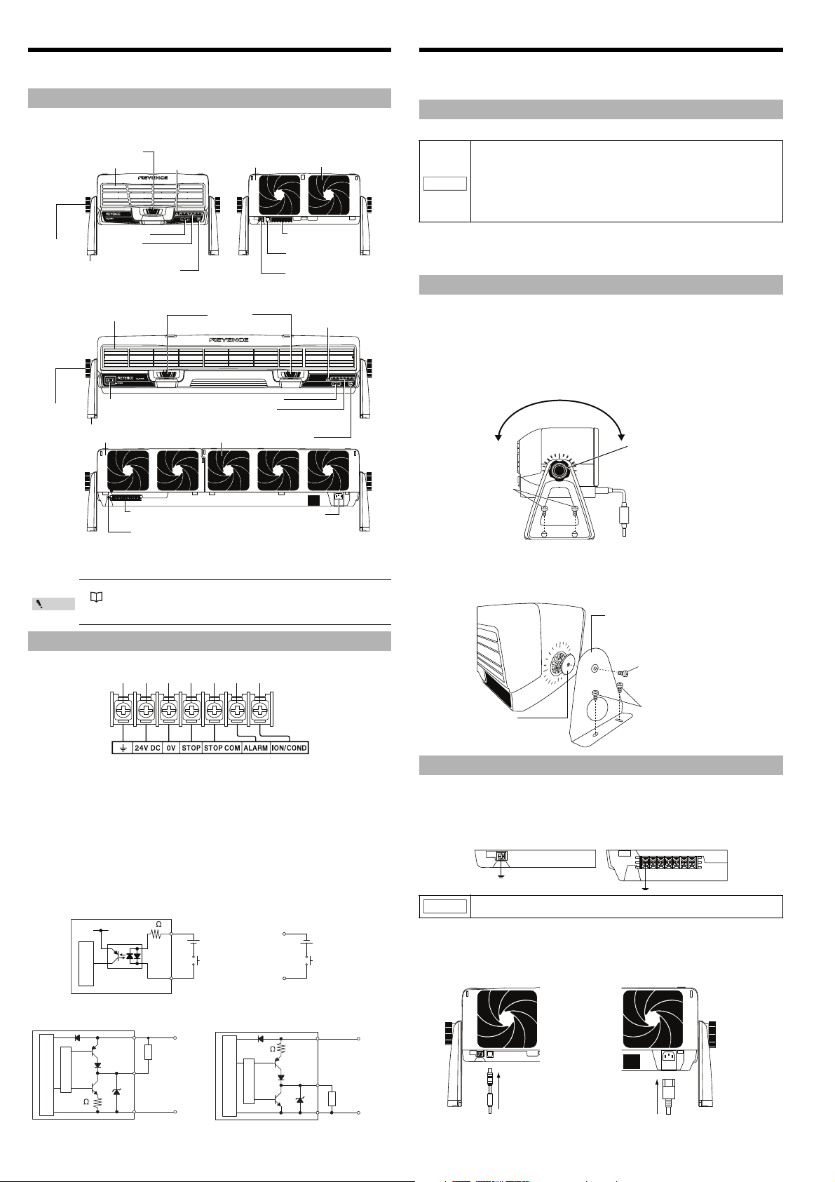
Loosen the angle fixing knob
to adjust the angle.
M4 screw
L-type mounting bracket
SJ-F2000 series: OP-87147
SJ-F5000 series: OP-87148
Buffer rubber
M5 screw
SJ-F2000 series: M5 screw
SJ-F5000 series: M8 screw
For SJ-F2000/SJ-F5000
SJ-F2500/SJ-F5500
For SJ-F2010/SJ-F5010
Installation and Connection
The package of SJ-F2000/5000 Series includes the following items. Ensure that these items are
included in your package before using the Unit. The name of each part is as follows.
Package content and part names
• Static Elimination Blower Unit
SJ-F2000 series
Angle fixing
knob
SJ-F5000 series
Lock switch
Front cover
Cursor key
Indicator
5 LEDs for SJ-F2000/SJ-F2010
7 LEDs for SJ-F2500
Stand
START/STOP button
Condition/Ion level
Alarm indicator
Rear cover
Air filter
Input/output terminal
block (SJ-F2010 only)
24 V DC IN connector
(SJ-F2000/SJ-F2500 only)
Ground terminal
(SJ-F2000/SJ-F2500 only)
This section explains how to set up and install the SJ-F2000/5000 Series.
Before installation, carefully verify the installation precautions for the SJ-F2000/5000 Series
and confirm the distance to the target object.
Precautions for installation
Installation location
• Keep a space of at least 50 mm around the front and the rear of the
SJ-F2000/5000 Series.
• Keep a space of at least 20 mm around the bottom of the SJ-F5000 series.
• The installation location should withstand a load of at least 8 kg for the
NOTICE
Interference
SJ-F2000/5000 Series may not operate properly if multiple SJ-F2000/5000 Series are
installed close together, or if there are electrical conductors in the vicinity. Provide at least
SJ-F2000 series, and 20 kg for the SJ-F5000 series.
• Keep a tightening torque of no more than 1.5 N•m for the included stand,
the L-type mounting bracket, and the U-type mounting bracket (The
recommended tightening torque is 1.0 - 1.2 N•m).
50 mm of space when installing the unit.
Installing SJ-F2000/5000 Series
There are two ways to install the SJ-F2000/5000 Series. The first is by using the stand
provided with this product, and the other is by using the L-type mounting bracket (SJ-F2000
series: OP-87147, SJ-F5000 series: OP-87148) or U-type mounting bracket (SJ-F2000 series:
OP-87149, SJ-F5000 series: OP-87150).
Installation method
z Using the stand
Drill and tap (M4) the location where the SJ-F2000/5000 Series is to be installed, and
then use the M5 screw to secure the included stand.
• Instruction Manual x 1
• Grounding cable x 1
• A power supply is necessary to use SJ-F2000/5000 Series.
See "Installation and Connection" (page 2)
• The 0V and ground terminals for the 24 V DC IN connector of the SJ-F2000/
SJ-F2500 are non-insulated.
Input/output terminals (SJ-F2010/5010 only)
Layout of the input/output terminal block
[1] Ground terminal: Be sure to ground at a resistance not exceeding 100 Ω.
[2] 24 V DC terminal: DC24 ±10%
[3] 0V terminal: 0V for power and various alarm output
[4] Static elimination interruption input: To turn static elimination on/off, connect the DC24 V
voltage between [4] and [5].
[5] COM for static elimination interruption: COM terminal for static elimination interruption
[6] Alarm output terminal: Output when there is an alarm.
[7] Condition/Ion level alarm output terminal:
Output when the installation environment prevents static elimin ation from being properly executed or causes the
ion generation amount to decrease.
* The ground connection terminal [1] and the 0V terminal [3] are internally isolated.
Input/output circuit and the wiring method (SJ-F2010/5010 only)
z Input circuit [static elimination interruption input]
[1] [2] [3] [4] [5] [6] [7]
z Using L-type mounting bracket for the SJ-F2000/5000 series
(SJ-F2000 series: OP-87147, SJ-F5000 series: OP-87148)
Mount the SJ-F2000/5000 Series on the L-type mounting bracket for the SJ-F2000/5000
series. Drill and tap (M5) the location where the SJ-F2000/5000 Series is to be installed,
and then secure the bracket.
Connecting the SJ-F2000/5000 Series
Connecting the grounding cable
Connect the provided grounding cable to the rear ground terminal, and then connect the
cable to the ground. For SJ-F2010/SJ-F5010, connect the provided grounding cable to the
ground connection terminal of the input/output terminal block.
For proper static elimination, be sure to ground the SJ-F2000/5000 Series at a
NOTICE
resistance not exceeding 100 Ω.
Connecting to the power supply
To connect to the power supply, use one of the following methods.
.
For SJ-F2000/2500
Connect the AC adapter to the 24 VDC IN connector.
If a 24V power supply is being used, make sure
to use the 24VDC IN cable (OP-87152).
.
For SJ-F5000/5500
Connect the AC cordset to the
AC power supply inlet.
z Output circuit [Alarm, condition ion level alarm output]
2
Page 3

.
Reference
.
SJ-F2500/SJ-F5500
.
SJ-F2000/SJ-F2010/SJ-F5000/SJ-F5010
Reference
.
For SJ-F2000/SJ-F5000/SJ-F2010/SJ-F5010
Red Red
Orange Green Orange
Red Red
Red
Orange Green Orange
Red
· SJ-F2500/SJ-F5500 ·
SJ-F2000/SJ-F2010/SJ-F5000/SJ-F5010
.
Keylock ON
.
Keylock OFF
CAUTION
NOTICE
Push the stopper
towards the outside.
Pull out the
board.
For SJ-F2010/5010
Connect a DC24 V power supply (Class 2 or LPS) with sufficient output capacity to the power terminals ([2] and [3]).
[1] [2] [3] [4] [5] [6] [7]
For the power source, use a DC power supply with sufficient marginal output
at a rated voltage of 24 V (output capacity per each blower must exceed the
NOTICE
following values; SJ-F2000: 0.9 A, SJ-F2500: 1.2 A, SJ-F2010: 1.0 A, SJ-F5010:
1.9 A).
Before using the unit, wait approx. 20 minutes after the unit is turned on.
Point
Otherwise, the ion balance may not be stabilized.
Operation and Function
Display and output specifications
Status
Power OFF
Normal operation
Static elimination
interrupted
Ion amount decreased
Condition abnormal
Ion amount decreased
and condition abnormal
<Alarm level 1>
Front cover removed
<Alarm level 2>
Internal memory value abnormal
Abnormal discharge Fan damaged
Static elimination
interruption input
-- -OPENOPEN
Open
Short
-
-
-
-
-
Indicator
Indicates the
electric charge level
Left and right edge
red LED illuminate
Indicates the
electric charge level
Indicates the
electric charge level
Indicates the
electric charge level
Three middle LEDs flash
(ON OFF ON OFF)
All LEDs flash
(ON OFF ON OFF)
Condition/ion
level alarm
indicator
Tur n o ff Sh or t OP EN
Tur n o ff OP EN OP EN
Red LED flashes
(ON OFF ON OFF)
Red LED flashes
(ON ON OFF ON ON OFF)
Red LED flashes
(ON OFF ON OFF)
Tur n o ff OP EN OP EN
Tur n o ff OP EN OP EN
Alarm
output
Short Short
Short Short
Short Short
Ion level
condition
alarm output
Initialization
Returns all of the settings to the factory defaults. While pressing the and cursor keys simultaneously,
turn on the power. The indicators illuminate, as shown below. Release the keys to start operation.
Powe r on
z For the SJ-F2000 series, SJ-F5010
Connect the power supply. The power turns on automatically.
z For the SJ-F5000 series (Except SJ-F5010)
Connect the power supply, and then turn on the power switch of the blower.
Start/stop static elimination
Static elimination starts automatically when the power is turned on.
Static elimination starts or stops when the START/STOP button is pressed and held down for
approx. 1 second during operation.
The indicator turns on when static elimination is interrupted, as shown below.
* The airflow stabilizes approx. 20 seconds after operation starts.
External interruption of static elimination (SJ-F2010/5010 only)
To save energy when 24 V DC voltage is connected between rear terminals [4] and [5], static
elimination and the fan can be interrupted while the power is on.
See "Input/output circuit and the wiring method (SJ-F2010/5010 only)" (page 2).
Control the airflow
Adjust the airflow by using the or
cursor keys.
The indicator LED flashes in response to the
airflow change.
Reduces airflow
Increases airflow
Press and hold down or
to continue adjusting the
airflow.
After you release the cursor key, the set value indicated by the LED flashes for approx. 5 seconds
and returns to the display that indicates the electric charge level. To set the airflow to the initial
value, press and hold down both cursor keys simultaneously for approx. 2 seconds.
Electric charge level display function
Confirms the electric charge level of the target.
The plus and minus side LEDs of the indicator will illuminate in response to the current charge
level of the target.
The further away from the center the illuminated LED is, the higher the electric charge level.
When static elimination is finished, the green LED in the middle of the indicator will be illuminated.
Alarm output/display function
The LED illuminates or flashes to indicate the current status.
SJ-F2010/5010 outputs the signal from the rear input/output terminal block.
The main indicator displays any decreases or abnormalities in ion generation.
Keylock function
While using the keylock function, operations other than using the START/STOP buttons can be
locked to prevent the accidental operation of buttons.
While pressing the cursor key, turn on the power. The indicators illuminate, as shown below.
After you release the cursor key, the display switches to the electric charge level display and
static elimination begins. To turn keylock off, repeat the above procedure.
* Operate with the front cover closed.
Output verification (SJ-F2010/5010 only)
The alarm, the ion level alarm, and the condition alarm are turned on and off manually. (to verify
output terminal operation)
While pressing the START/STOP button and the and cursor keys simultaneously, turn on
the power. The indicators illuminate, as shown below.
For various outputs, while pressing the cursor key, turn on the power, and while pressing the
cursor key, turn off the power. Static elimination is interrupted while output is being verified.
Power ON again to restart static elimination.
* Operate with the front cover closed.
NPN/PNP output switching (SJ-F2010/5010 only)
The PNP and NPN output are used to switch the output circuit. The initial setting is NPN.
* Operate with the front cover closed.
•NPN
While pressing the cursor key and the
START/STOP button simultaneously, turn on the
power.
Release the buttons to start static elimination.
•PNP
While pressing the cursor key and the
START/STOP button simultaneously, turn on the
power.
Release the buttons to start static elimination.
Maintenance of Electrode Probes
When the SJ-F2000/5000 Series is used for a long period, the electrode probes become dirty due
to the accumulation of dust.
If you continue to use the SJ-F2000/5000 Series with dust accumulating on the electrode probes,
the static elimination ability may deteriorate, resulting in an accident or product breakdown.
Therefore, be sure to clean the electrode probes periodically.
Maintenance of electrode probes
• Turn off the SJ-F2000/5000 Series before the maintenance of the electrode probes.
• Do not touch the electrode probes directly with your hand or fingers, as
this may cause injury. Be extremely careful when cleaning them.
Be sure to mount the electrode probes so that they are facing in the correct
direction, as described here.
Cleaning the electrode probes
Use a cotton swab soaked in alcohol to softly wipe the electrode probes.
1 Slide the lock switch located on the face of the
front cover. After you slide the lock switch,
press the tab at the upper part of the front
cover, and then pull the front cover towards
you to remove it.
2 Push the stopper, which is to the right of the
slot, towards the outside. This is the stopper
used to set the board for the electrode probes.
Pull out the board for the electrode probes.
* To mount the board, perform the above procedure in
the reverse order.
3
Page 4

Copyright (c) 2010 KEYENCE CORPORATION. All rights reserved.
11352E 1060-1 96M11352
Printed in Japan
Changing the electrode probes
Power supply
Static elimination
interruption input
(Input terminal)
Static elimination
interruption input
(START/STOP button)
Ion generation
status
Alarm output
(Output terminal)
Normally
ON
Normally
OFF
NormallyONForced
OFF
NormallyONNormally
OFF
NormallyONForced OFF Normally
ON
150ms 150ms 150ms 150ms
MAX
150ms
ON
OFF
ON
OFF
ON
OFF
ON
OFF
ON
OFF
Replace the electrode probe if the static elimination capability fails to recover after you clean the
electrode probe, or if the red alarm for the condition/ion level indicator flashes (ON OFF ON OFF)
frequently. Prepare the optional electrode unit for replacement (SJ-F2000 series: OP-87153,
SJ-F5000 series: OP-87154).
To mount an electrode probe, perform the cleaning procedure in the reverse order. Follow the
steps described in "Start/stop static elimination" (page 3) and resume static elimination.
Cleaning the rear air filter
If the airflow level for the static elimination blower decreases, or if the air filter becomes dirty, take
out the rear cover and use cleaner or a similar agent to remove the dust from the inside filter.
Changing the fuse
When the fuse blows, replace the fuse in the fuse holder located under the AC inlet. Be sure to use a
fuse rated 250V, 1.6A, Time lag. (Recommended fuse: ET series manufactured by SOC Corporation)
Timing Charts
* The static elimination interruption input (input terminal) and the alarm output (output terminal)
are only for SJ-F2010/5010).
Warnings and Remedies
Refer to the following list for troubleshooting and remedies before sending out the unit for repairs.
Problem Inspection Remedy
Neither the indicator
nor the pilot lamp turns
ON.
No static elimination is
performed.
Ion level (ION LEVEL)
alarm is illuminated and
output.
The power is ON but
the fan does not rotate.
The condition (COND)
alarm is illuminated and
output.
Control output is not
output correctly.
Static elimination
interrupt input is not
input properly.
There is little airflow.
The three middle
indicators flash.
All indicators flash.
Check that the power supply cable is
connected correctly.
Check that the power supply is within
the rated range.
Check that the electrode probes are
not worn out or dirty.
Check that static elimination is not
interrupted.
Check that the electrode probes are
not worn out or dirty.
Check that there is no conductive object
within 50 mm of the ele ctrode probes.
Check that the wiring is correct.
Check that static elimination has not
been interrupted.
Check that there is no conductive
object or another Static Eli minator Unit
close to the SJ-F2000/5000 Series.
Check that the cable is wired correctly.
Check that the cable is wired correctly.
Check that the airflow setting is not
too low.
Check that the rear filter is not clogged. Remove the dust and contaminant clogged in the filter.
Check that the front cover has not
been removed.
Abnormal discharge from the tip of
the electrode probe
Ground cable is not c onnected Verify that the ground cable is actually connected.
Abnormal value for the internal
memory
Fan is damaged Contact the nearest KEYENCE office.
Follow the steps in "Connecting to the power
supply" (page 2) to correctly connect the cable.
Use power supply within the rated range.
Follow the steps in "Maintenance of Electrode
Probes" (page 3) to perform maintenance or
replace electrode probes.
Follow the steps in "Operation and Function"
(page 3) to start static elimination.
Follow the steps in "Maintenance of Electrode
Probes" (page 3) to perform maintenance or
replace electrode probes.
Make sure there are no electrically conductive objects
within 50 mm of the front of the Static Eliminator Unit.
Follow the steps in "Connecting the grounding cable"
(page 2) to correctly connect the grounding cable.
Follow the steps in "Operation and Function"
(page 3) to start static elimination.
Keep the SJ-F2000/5000 Series away from the
conductive object or the Static Eliminator Unit.
Check the output circuit and make sure that the
wiring is correct.
Verify the input circuit and the wiring and
connect correctly according to "Input/output
circuit and the wiring method (SJ-F2010/5010
only)" (page 2).
Follow the steps in "Control the airflow" (page
3) to verify the settings.
Correctly mount the front cover, and then press and
hold the START/STOP button for approx. 2 seconds.
Turn off the power and perform maintenance on the
electrode probe. If the alarm persists even after you
perform maintenance, remove any conductive
objects that may be near the Static Eliminator Unit.
Follow the steps described in "Initiali zation"
(page 3) and initialize the SJ-F2000/5000 Series.
If the alarm persists even after the initiali zation,
contact the nearest KEYENCE office.
Specifications
Static Eliminator Unit main body
Control
input
Control
output
Rating
Environ
ment
*1 Measured at a distance of 300 mm from the front side of the fan
*2
Measured at a distance of 300 mm from the front side of the fan, using the maximum air flow rate
WARRANTIES AND DISCLAIMERS:
(1) KEYENCE warrants the Products to be free of defects in materials and workmanship for a
period of one (1) year from the date of shipment. If any models or samples were shown to
Buyer, such models or samples were used merely to illustrate the general type and quality of
the Products and not to represent that the Products would necessarily conform to said models
or samples. Any Products found to be defective must be shipped to KEYENCE with all
shipping costs paid by Buyer or offered to KEYENCE for inspection and examination.
Upon examination by KEYENCE, KEYENCE, at its sole option, will refund the purchase price
of, or repair or replace at no charge any Products found to be defective.
This warranty does not apply to any defects resulting from any action of Buyer, including but
not limited to improper installation, improper interfacing, improper repair, unauthorized
modification, misapplication and mishandling, such as exposure to excessive current, heat,
coldness, moisture, vibration or outdoors air. Components which wear are not warranted.
(2) KEYENCE is pleased to offer suggestions on the use of its various Products. They are only
suggestions, and it is Buyer's responsibility to ascertain the fitness of the Products for Buyer’s
intended use. KEYENCE will not be responsible for any damages that may result from the use
of the Products.
(3) The Products and any samples ("Products/Samples") supplied to Buyer are not to be used
internally in humans, for human transportation, as safety devices or fail-safe systems, unless their
written specifications state otherwise.
Should any Products/Samples be used in such a manner or misused in any way, KEYENCE
assumes no responsibility, and additionally Buyer will indemnify KEYENCE and hold KEYENCE
harmless from any liability or damage whatsoever arising out of any misuse of the Products/
Samples.
(4) OTHER THAN AS STATED HEREIN, THE PRODUCTS/SAMPLES ARE PROVIDED WITH NO
OTHER WARRANTIES WHATSOEVER. ALL EXPRESS, IMPLIED, AND STATUTORY
WARRANTIES, INCLUDING, WITHOUT LIMITATION, THE WARRANTIES OF
MERCHANTABILITY, FITNESS FOR A PARTICULAR PURPOSE, AND NON-INFRINGEMENT
OF PROPRIETARY RIGHTS, ARE EXPRESSLY DISCLAIMED.
IN NO EVENT SHALL KEYENCE AND ITS AFFILIATED ENTITIES BE LIABLE TO ANY
PERSON OR ENTITY FOR ANY DIRECT, INDIRECT, INCIDENTAL, PUNITIVE, SPECIAL OR
CONSEQUENTIAL DAMAGES (INCLUDING, WITHOUT LIMITATION, ANY DAMAGES
RESULTING FROM LOSS OF USE, BUSINESS INTERRUPTION, LOSS OF INFORMATION,
LOSS OR INACCURACY OF DATA, LOSS OF PROFITS, LOSS OF SAVINGS, THE COST OF
PROCUREMENT OF SUBSTITUTED GOODS, SERVICES OR TECHNOLOGIES, OR FOR ANY
MATTER ARISING OUT OF OR IN CONNECTION WITH THE USE OR INABILITY TO USE THE
PRODUCTS, EVEN IF KEYENCE OR ONE OF ITS AFFILIATED ENTITIES WAS ADVISED OF A
POSSIBLE THIRD PARTY’S CLAIM FOR DAMAGES OR ANY OTHER CLAIM AGAINST
BUYER. In some jurisdictions, some of the foregoing warranty disclaimers or damage
limitations may not apply.
BUYER'S TRANSFER OBLIGATIONS:
If the Products/Samples purchased by Buyer are to be resold or delivered to a third party, Buyer
must provide such third party with a copy of this document, all specifications, manuals, catalogs,
leaflets and written information provided to Buyer pertaining to the Products/Samples.
Item Specifications
Model SJ-F2500 SJ-F2000 SJ-F5500 SJ-F5000 SJ-F2010 SJ-F5010
Voltage application method Pulse AC method
Applied voltage ±7000 V
Ion balance control method I.C.C.
Static elimination time
Operating distance More than 50 mm
Maximum air speed
Maximum air flow rate 4.0 m
Ozone concentration Less than 0.005 ppm
*1
Ion balance
Static elimination
interruption input
NPN open
Alarm/Ion
level alarm/
Condition
collector
PNP open
alarm
collector
Power supply DC24 V ±10%
Current consumption 1.2 A 0.9 A 90 VA 65 VA 1.0 A 1.9 A
Ambient temperature 0°C - 50°C
Relative humidity 35% - 65%
Overvoltage category II
Pollution degree 2
Weight About 2 kg About 2 kg About 5 kg About 5 kg About 2 kg About 4 kg
About
*2
*1
About
0.6 sec
1.0 sec
5.7 m/s 3.5 m/s 5.7 m/s 3.5 m/s 3.5 m/s 3.5 m/s
3
/min 2.5 m3/min
±5 V
About
About
0.6 sec
1.0 sec
10.0 m3/min
6.2 m3/min 2.5 m3/min 6.2 m3/min
- DC24 V input
-
-
AC100 - 240 V
(50/60 Hz)
100 mA (Less than 40 V)
(Residual voltage 1 V or less)
(Residual voltage 3 V or less)
About
About
1.0 sec
1.0 sec
100 mA (24 V ±10%)
DC24 V ±10%
External Dimensions
Main body (with stand attached)
D
E
C
φ
A
183.5
135.5
B
Item SJ-F2500 SJ-F2000 SJ-F2010 SJ-F5500 SJ-F5000 SJ-F5010
A 115 135
B 68.5 48.5
C35 45
D 302.9 638.8
E 252 582
F 126 153.7/428.3
G 287 617
H 50 65.5
F (Lever center)
10.6
G (φ4.5 hole pitch)
Removable
front cover
50 133 50
(70.5)
113
φ
4.5 hole × 4
50 (φ4.5 hole pitch)
69
Rotatable
360 degrees
Removable
filter
H
(Cable projection
distance)
<Unit: mm>
4
 Loading...