

Page 1
Before using this Free-layout Elimination Blower,
be sure to thoroughly read this Instruction Manual.
After you are finished with this Instruction Manual,
be sure to store it in a safe place for quick reference.
High-speed, High-precision
Free-layout Static Elimination Blower
Instruction Manual
300
Series
96M10106
1
Page 2
Preface
This document describes handling, method of operation and precautions when using the High-speed,
High-precision Free-layout Elimination Blower Unit SJ-F300 Series. Before you start to use the SJF300 Series, be sure to thoroughly read this document in order to make full use and safely use the
functions of the SJ-F300 Series.
Store this document in a safe place so that you can retrieve it whenever necessary.
■ Symbols
This manual uses the following symbols to alert you to important information.
Be sure to read below.
Failure to follow these instructions may lead to death or serious injury.
Failure to follow these instructions may lead to injury.
Failure to follow these instructions may lead to physical damage (product
malfunction, etc.).
Provides additional information on precautions and restrictions that must be
followed in operation.
Provides additional information on proper operation.
Indicates useful information or information that aids understanding of text descriptions.
Indicates a reference item or page to be referred to in this manual and a separate manual.
DANGER
WARNING
CAUTION
Important:
Note:
Tip
Safety Precautions
■ General Precautions
• At startup and during operation, be sure to monitor the functions and
performance of the SJ-F300 Series.
• We recommend that you take substantial safety measures to avoid any
damage in the event that a problem occurs.
• Do not modify the SJ-F300 Series or use it in any way other than described
in the specifications. The functions and performance of products used or
modified in this way cannot be assured.
• When the SJ-F300 Series is used in combination with other instruments,
functions and performance may be degraded, depending on operating
conditions and the surrounding environment.
• Do not use the SJ-F300 Series for the purpose of protecting the human
body.
■ SJ-F300 Series Handling Precautions
The SJ-F300 Series is a high-voltage product that is not designed in an explosion-proof structure. Pay
attention to the following when using the SJ-F300 Series.
• To prevent electric shock and to ensure accurate static elimination, be sure
to connect a Class D earth (maximum resistance of 100 Ohms).
• Do not use this product in locations where there is the risk of ignition or
explosion from flammable solvents or dirt and dust.
• High voltage is applied to this product. Prevent it from being splashed with
water, oil, or flammable solvents. Failure to do so may cause insulation
breakdown, which will result in electric shock or malfunction.
• Do not bring your fingers or tools, wire or other metallic objects near this
product. Doing so may cause electric shock or malfunction.
• Do not use this product in a non-ventilated location. The ozone generated
from this product may become toxic. Be sure to ventilate the installation site
when this product is used in a non-ventilated location.
• Do not use this product in locations where sudden changes in temperature
or condensation are likely to occur. Doing so may cause accidents or
malfunction.
• Do not operate this product with wet hands. Doing so may cause electric
shock.
• Before starting maintenance, be sure to turn the power OFF. Failure to do so
may result in electric shock or accidents.
• During maintenance, do not directly touch the electrode needles. Doing so
may cause personal injury.
• If any malfunction is observed in this product, immediately turn it OFF, and
contact your nearest agent. You should never repair this product yourself.
Doing so may cause electric shock or malfunction.
Do not touch the electrode needles with a tool or other hard object. Damage to
the electrode needles will prevent static elimination performance from being
fully demonstrated, and cause accidents or malfunction.
CAUTION
WARNING
CAUTION
• When this product is used for a long period of time, the electrode needles
become dirty due to the adhesion of dust and dirt. If the ion level alarm
indicator or condition alarm indicator lights, clean the electrode needles. If
the electrode needles are used in a dirty or dusty state, the static elimination
performance can no longer be fully demonstrated, resulting in accidents or
malfunction. We recommend periodically cleaning the electrode needles (as
a guideline, once every two weeks in a regular operating environment
though this depends on the installation conditions ).
• Do not drop or subject this product to shock. Doing so may result in
accidents or malfunction.
• Use this product for static elimination only. Do not use it for other purposes.
■ Power Supply Precautions
• Use a DC power supply with rated 24 V output.
• Noise applied to the power supply may cause this product to malfunction. If
this happens, install an insulated transformer.
• When using a switching regulator, be sure to connect a Class D earth to the
Frame Ground terminal.
■ Grounding Precautions
• To ensure safety and appropriate static elimination, be sure to ground this
product.
• Be sure to connect a Class D earth (maximum resistance of 100 Ohms).
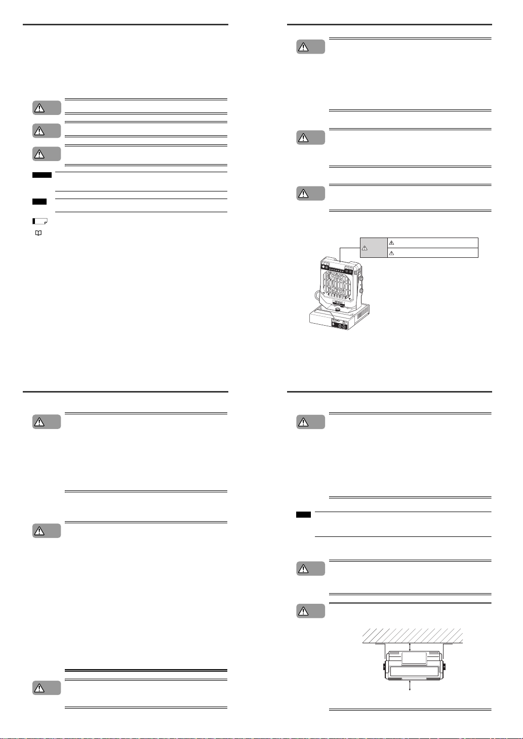
■ SJ-F300 Series Warning Label
A WARNING label is affixed on the SJ-F300 Series to ensure safety.
Read the description on this WARNING label to ensure correct use of the SJ-F300 Series.
CAUTION
CAUTION
CAUTION
Be sure to turn the power off when replacing
the electrode probes. Otherwise, electric shock may occur.
Do not touch electrode probes with your hands
or fingers, as this may cause injury.
WARNING
* WARNING labels in Japanese, German, French, Italian and Chinese:SC
are provided.
Use them as necessary.
STAR
T
/STOP
BALANCE
ION
FAN
COND
IONLEVEL
■ Installation Precautions
Avoid installing the SJ-F300 Series in the following locations as this may
cause accidents.
• Locations directly subject to vibration and shock
• Locations subject to ambient temperature out of the 0°C to +50°C range
• Locations subject to ambient humidity out of the 35 to 65%RH range
(condensation not allowed)
• Locations subject to sudden changes in temperature
• Locations subject directly from blasts from air conditioners
• Locations subject to volatile or flammable substance, solvents or corrosive
gases
• Locations subject to large amounts of dirt, and dust, salt, iron and oil smoke
• Locations that may be splashed with water, oil or chemical mist
• Locations where strong magnetic and electrical fields are generated
■ About Warming Up the SJ-F300 Series
Leave the SJ-F300 Series for about 20 minutes after turning the power ON to allow
the ion balance to stabilize.
The ion balance may be unstable during this warming up period.
■ Other Precautions
•
Be sure to read the WARNINGS and CAUTIONS described in each of the
items in this Instruction Manual.
•
The Static Elimination Blower Unit has a built-in EEPROM. Do not turn the
Static Elimination Blower Unit OFF during the setup.
Refer to the following diagram when installing the SJ-F300 Series.
• Install the Static Elimination Blower Unit away from the wall or surroundin g
objects.
• Install the Static Elimination Blower Unit so that the Electrode Unit can be
removed for replacement.
CAUTION
Note:
CAUTION
CAUTION
50 mm or more
50 mm or more
1
Page 3
Precautions on Regulations and Standards
■ CE Marking
Keyence Corporation has confirmed that this product complies with the essential requirements of the
applicable EC Directive, based on the following specifications.
Be sure to consider the following specifications when using this product in the Member State of
European Union.
● EMC Directive (2004/108/EC)
• Applicable standard EN61326-1
• Be sure to provide a ground when installing the SJ-F300 Series.
• The length of cable (power lead and I/O leads) must be less than or equal to 30 m.
Remarks:
These specifications do not give any guarantee that the end-product with this product incorporated
complies with the essential requirements of EMC Directive. The manufacturer of the end-product is
solely responsible for the compliance on the end-product itself according to EMC Directive.
● Low-Voltage Directive (2006/95/EC)
• Applicable Standard : EN61010-1
• Overvoltage category I
• Use this product under pollution degree 2.
• Use the power supply for the SJ-F300 Series, that satisfies the requirements of the Limited Power
Source specifications stipulated in EN60950-1 and certified by European third-party certification
organization, or a Keyence Corporation AC adapter (SJ-U2). The specifications of the AC adapter
(SJ-U2) are as follows.
• When connecting to an SJ-U2, be sure to use a power cable compliant with European standards.
Applicable standard: EN60950-1
Overvoltage category II
Pollution degree 2
• Be sure to provide a ground when installing the SJ-F300 Series.
1ABOUT THE STATIC ELIMINATION BLOWER UNIT SJ-F300 SERIES
1-1 System Configuration
This section describes the system configuration of the Static Elimination Blower Unit SJ-F300 Series.
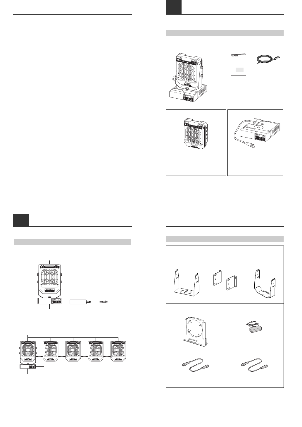
System Configuration
■ When used independently
■ When used in connection
Maximum number of the Static Elimination Blower Units connectable to one Controller Unit is five.
to AC power
Controller Unit AC adapter
Static Elimination Blower Unit
to 24 VDC power
Controller Unit
Static Elimination Blower Units
1-2
Checking the Contents of the Package
The package contains the following components and accessories. Before getting started, make sure
that the package contains everything that it is supposed to contain.
Package Contents
■ When you purchased as a set
■ When you purchased independently
START
/STOP
BALANCE
ION
FAN
COND
IONLEVEL
• Body • Instruction Manual • Earth lead
• Warning label (Japanese, German, French, Italian,
Chinese: SC)
* Use as necessary.
SJ-F
300
Series
High-speed, High-precision
Free-layout Static Elimination Blower
Instruction Manual
Before using this Free-layout Elimination Blower,
be sure to thoroughly read this Instruction Manual.
After you are finished with this Instruction Manual,
be sure to store it in a safe place for quick reference.
Attached to the main
unit when shipped
from the factory.
START
/STOP
BALANCE
ION
FAN
COND
IONLEVEL
• Static Elimination Blower Unit (SJ-F030/F035) • Controller Unit (SJ-F300)
• Warning label
(Japanese, German, French, Italian, Chinese: SC)
* Use as necessary.
* When purchased the Static Elimination Blower
Unit independently, note that a mounting fixture
is not included.
• Earth lead
• Instruction Manual
1-2
Checking the Contents of the Package
Options
* • Total cable length cannot exceed 20 m.
(One unit: 20 m, Two units: 15 m, Three units or more: 10 m)
• To connect the blowers with a cable other than that of 2, 5 and 10m, use the blower-blower extension
cable (SJ-C * P) in combination with a controller-blower extension cable (SJ-C * J).
Mounting fixture A (OP-78476)
Accessory: M4 screw for fixing
the Static
Elimination Blower
Unit x 4
Mounting fixture B (OP-78477)
Accessory: M4 screw for fixing
the Static
Elimination Blower
Unit x 4
Mounting fixture C (OP-78478)
Accessory: M4 fixing screw x 6
Electrode Unit for exchanging (OP-51407) AC adapter (SJ-U2)
Capable of driving up to one fan.
For details of the AC cable, contact the KEYENCE
sales office in your district.
Controller-Blower extension cable * Blower-Blower extension cable *
SJ-C2J Plug-Jack at both ends 2 m
SJ-C5J Plug-Jack at both ends 5 m
SJ-C10J Plug-Jack at both ends 10 m
SJ-C02P Plug-Plug at both ends 0.2 m
SJ-C2P Plug-Plug at both ends 2 m
SJ-C5P Plug-Plug at both ends 5 m
SJ-C10P Plug-Plug at both ends 10 m
2
Page 4
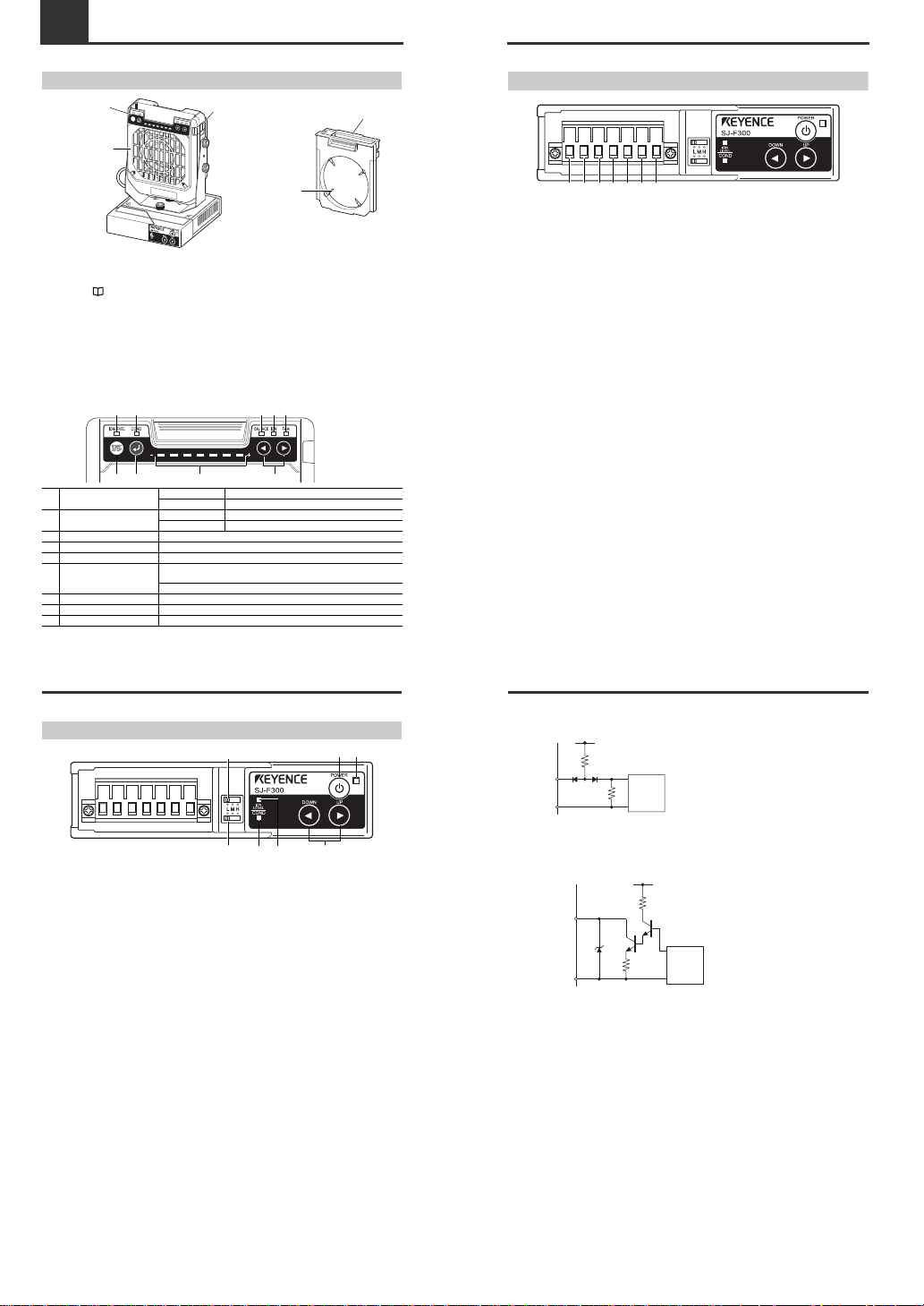
1-3 Names and Functions of Parts
Static Elimination Blower Unit
Electrode Unit
Provided with the electrode needles. Remove from the Static Elimination Blower Unit before attempting
maintenance and servicing work.
Refer to "Performing Maintenance on the Electrode Needles" (page 9) for details about how to
remove the Electrode Unit.
Electrode needle
Generates ions from its tip.
Lock switch
Fixes the Electrode Unit to the Static Elimination Blower Unit.
Fan guard
SJ-F030: Metal
SJ-F035: Resin
■ Operation panel
START
/STOP
BALANCE
ION
FAN
COND
IONLEVEL
Lock switch
Static elimination blower
unit operation panel
Fan guard
Electrode Unit
Electrode needle
[1] Ion level alarm indicator
Lit OFF Normal
Blinking in red Ion level alarm has occurred.
[2] Condition alarm indicator
Lit OFF Normal
Blinking in red Condition alarm has occurred.
[3] Ion balance indicator When lit, the indicator displays the ion balance.
[4] Ion level indicator When lit, the indicator displays the ion level.
[5] Blow rate indicator When lit, the indicator displays the blow rate setting value.
[6] Monitor
The monitor displays the ion balance, ion level, blow rate setting value in
seven indication levels.
Lights in red when the Static Elimination Blower Unit needs cleaning.
[7] START/STOP key Used for switching start/stop.
[8] ENTER key Used for selecting various setups.
[9] UP/DOWN key Used for selecting and adjusting various setups.
[1]
[6] [9]
[2] [3] [4] [5]
[7] [8]
1-3
Names and Functions of Parts
Controller Unit (Operation/Display Section)
[1] Power switch ..... Used for turning ON/OFF the SJ-F300 Series.
[2] Power indicator ..... Displays the power condition ON/OFF.
Lit in green : Normal
Lit OFF : Power OFF
Blinking in green : Static elimination stop inputted.
Blinking in red : Alarm has stopped.
[3] Blow rate adjusting key ..... Used for adjusting the blow rate of the Static Elimination Blower Units
being connected collectively.
[4] Ion level alarm indicator .....Blinks when the ion emission level has dropped below the setting value
due to dirt or wear of the electrode needles.
Lit OFF : Normal
Blinking in red : Ion level alarm has occurred.
Blinking in red : Alarm has stopped.
*
1
Double blinking : Under ion balancing
[5] Condition alarm indicator ....Blinks when the static elimination performance may be influenced by
instability of the installation environment (temperature, humidity,
surrounding metal objects, etc.), for example, when ions are being
absorbed by surrounding metal objects.
Lit OFF : Normal
Blinking in red : Condition alarm has occurred.
Blinking in red : Alarm has stopped.
*
1
[6] Ion level alarm sensitivity setup switch .....Used for changing the threshold value at which ion level
alarm is output.
H: High sensitivity
M: Medium sensit ivity
L: Low sensitivity
[7] Condition alarm sensitivity setup switch ..... Used for changing the threshold value at which condition
alarm is output.
H: High sensitivity
M: Medium sensit ivity
L: Low sensitivity
*
1 Alarm level 2, 3: [2], [4] and [5] blink simultaneously in red.
Alarm level 1: [2] blinks in red.
[6]
[1]
[3][4][5][7]
[2]
1-3
Names and Functions of Parts
Controller Unit (I/O Terminal Section)
[1] Ground terminal ..... Be sure to connect a Class D earth.
[2] DC power terminal ..... 24 VDC ±10%
[3] 0 V terminal ..... 0 V for power and 0 V for I/O
[4] Static elimination stop input terminal ..... Static elimination can be turned ON/OFF by shorting this
terminal with [3] or [5].
[5] 0 V terminal ..... 0 V for power and 0 V for I/O
[6] Alarm output terminal ..... Outputs a signal when alarm condition has occurred.
[7] Condition/Ion level alarm output terminal .... Outputs a signal when the static elimination
performance may be influenced by instability of the
installation environment, or when the ion emission level
has dropped.
[1] [2] [3] [4] [5] [6] [7]
1-3
Names and Functions of Parts
■ Input circuit diagram
[4] Static elimination stop input
■ Output circuit diagram
Open collector output
[6] Alarm output, [7] Condition/Ion level alarm output
+5 V
Internal
Circuit
470 Ω
10 kΩ
INPUT[4]
0 V[3], [5]
Input zero-voltage contact (relay, etc.) or NPN open
collector to INPUT or 0 V.
5 V
47 V
180 Ω
4.7 Ω
OUTPUT[6], [7]
40 VDC
100 mA
0 V[3], [5]
Internal
Circuit
3
Page 5
2CONNECTION AND INSTALLATION
2-1 Before Installation
Before you install this product, examine carefully the distance between the Static Elimination Blower
Unit and the target object and the time required for static elimination.
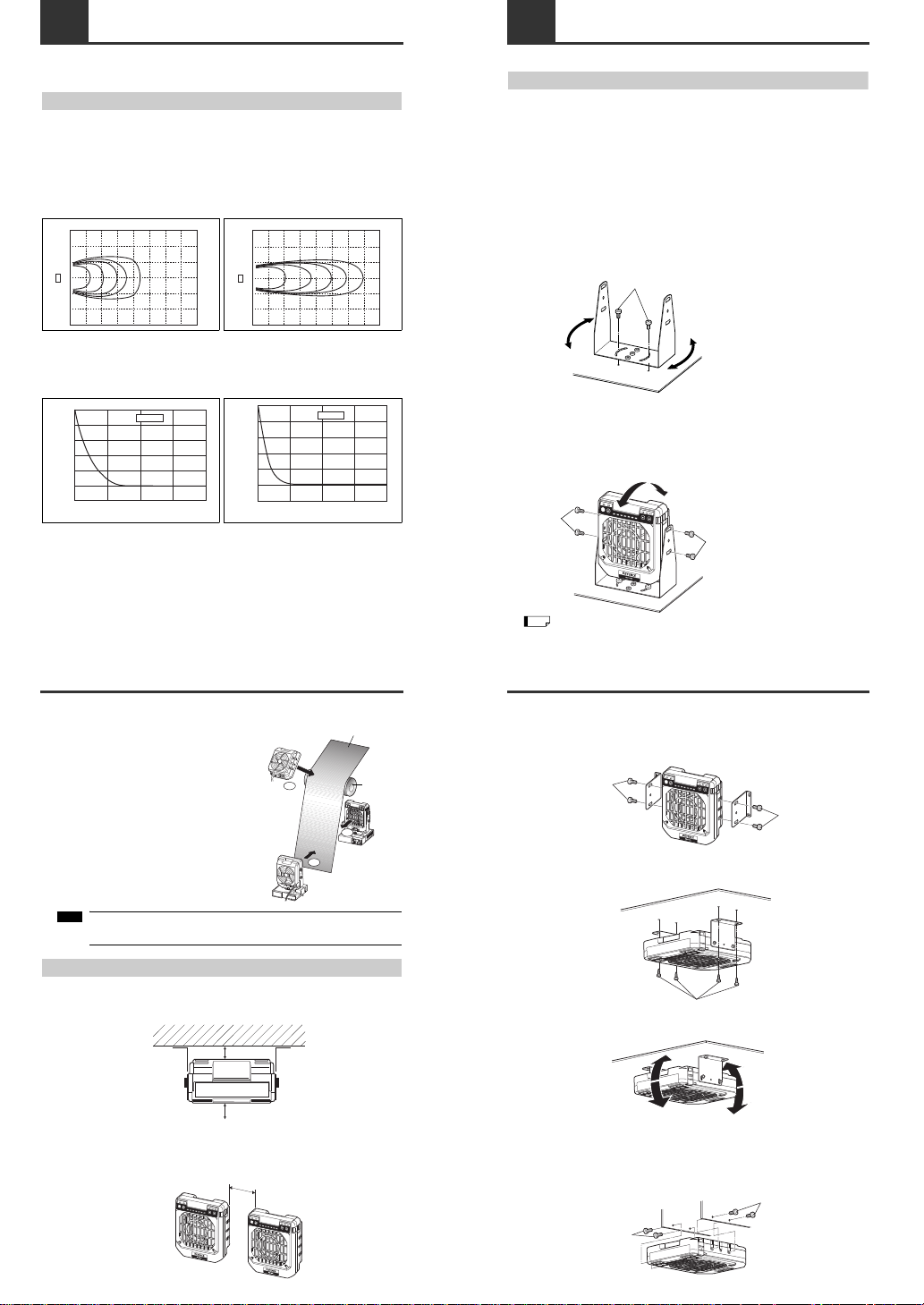
About Static Elimination Performance
The following shows a typical example where static is eliminated from an aluminum plate (20 pF)
150 mm x 150 mm square charged to +1000 V by this product.
The blow rate of the blower is set at maximum (FAST).
■ Static elimination area
The following graphs show the relationship between the time required for eliminating static from a target
object charged from +1000 V to +100 V and the distance from the charged object up to the Static
Elimination Blower Unit.
■ Static elimination time
The following graphs show the relationship between the time required for eliminating static at the
maximum blow rate from a target object charged at +1000 V positioned 300 mm apart from the Static
Elimination Blower Unit and the charged level.
200 400 800 1000 1200 1400 1600mm600
600mm
600mm
0
1s 2s 3s 4s 5s
SJ-F030
200 400 800 1000 1200 1400 1600mm600
600mm
600mm
0
1s 3s 4s 5s
SJ-F035
2s
01234
1
0.8
0.6
0.4
0.2
0
-0.2
Time required for static elimination (sec)
Charged level (kV)
SJ-F030
01234
1
0.8
0.6
0.4
0.2
0
-0.2
Time required for static elimination (sec)
Charged level (kV)
SJ-F035
2-1
Before Installation
■ Appropriate static elimination method
Pay attention to the following points to ensure that static
elimination is performed appropriately.
Static elimination cannot be performed accurately at
locations where the target object is touching a metallic
body (earthed body).
Eliminate static from the target body at locations where it is
not directly touching metallic bodies (earthed body).
Static will be eliminated from only the surface of the
insulated body (film, sheet, etc.) that is facing the Static
Elimination Blower Unit.
When eliminating static from both sides of a target body,
install two Static Elimination Blower Units as one unit must
be installed on either side of the target body.
Install the Static Elimination Blower Unit so that it can be easily accessed, for
example, for replacement of parts and cleaning.
Installation Precautions
■ Installation site
Refer to the following diagram when installing the SJ-F300 Series.
• Install the Static Elimination Blower Unit away from the wall or surrounding objects.
• Install the Static Elimination Blower Unit so that the Electrode Unit can be removed for replacement.
■ Interference
The Static Elimination Blower Unit may not function properly if two or more units are used close to each other.
In such an installation, refer to the following diagram and maintain the indicated distance between units.
START
/STO
P
BA
L
A
NC
E
ION
FAN
COND
I
O
N
L
E
VEL
OK
OK
NG
Film, sheet or other electrically charged object
Metal roller
Note:
50 mm or more
50 mm or more
STAR
T
/S
TOP
STAR
T
/S
TOP
15 mm or more
2-2 Connection and Installation
Installing the SJ-F300 Series
Install the SJ-F300 Series at locations where static electricity is generated or is likely to be generated.
When installing the Static Elimination Blower Unit separately from the Controller Unit, refer to
"■ Installing the Static Elimination Blower Unit" below.
■ Installing the Static Elimination Blower Unit
There are two ways of installing the Static Elimination Blower Unit, with or without the mounting fixtures.
Each installation method is shown below.
● When using mounting fixture A (OP-78476):
1 Tap M4 screw holes where the Static Elimination Blower Unit is to be installed, and fasten
mounting fixture A (OP-78476) with M4 screws.
You can adjust the horizontal angle of the Static Elimination Blower Unit by using the semi-circled
cutout holes on the base of mounting fixture A.
M4 screws for fastening mounting fixture A at the installation location must be provided separately.
2 Install the Static Elimination Blower Unit on mounting fixture A.
You can adjust the vertical angle of the Static Elimination Blower Unit by using the semi-circled cutout
holes on the base of mounting fixture A.
M4 screws for fastening mounting fixture A to the Static Elimination Blower Unit are provided with
mounting fixture A.
When using the accessory mounting fixture, also fasten it with screws as shown above.
M4 screws
STAR
T
/STOP
BALANCE
ION
FAN
COND
IONLEVEL
M4 screws
M4 screws
Tip
2-2
Connection and Installation
● When using mounting fixture B (OP-78477):
1 Install mounting fixture B (OP-78477) on the Static Elimination Blower Unit.
M4 screws for fastening the Static Elimination Blower Unit to mounting fixture B are provided with
mounting fixture B.
2 Tap M4 screw holes where the Static Elimination Blower Unit is to be installed, and fasten
mounting fixture B (OP-78477) with M4 screws.
M4 screws for fastening mounting fixture B to the installation location must be provided separately.
3
Loosen the screws mounted on the Static Elimination Blower Unit, and adjust the installation
angle. Then, fasten with the screws again.
● When mounting fixtures are not used:
Drill holes of diameter 4.2 mm or more at the location where the Static Elimination Blower Unit is to be
installed, and fasten with M4 screws.
M4 screws must be provided separately.
STAR
T
/STOP
BALANCE
ION
FAN
COND
IONLEVEL
M4 screws
M4 screws
START
/STOP
M4 screws
START
/STOP
S
T
A
R
T
/
ST
O
P
M4 screws
M4 screws
4
Page 6

2-2
Connection and Installation
Connecting Cables
When you have finished with installation, connect the earth lead, the connection cable for the Static
Elimination Blower Unit and the power supply.
■ Connecting the earth lead
Connect the accessory earth lead to the earth connection terminal on the side panel of the Controller
Unit, to conduct grounding.
Alternatively, you can connect the earth lead to the input terminal section on the front panel of
the Controller Unit.
(Refer to "Controller Unit (I/O Terminal Section)" on page 3)
To prevent electric shock and to ensure accurate static elimination, be sure to
connect a Class D earth.
■ Connecting the cable
Connect the connection cable of the Controller Unit to the input terminal [IN] of the Static Elimination
Blower Unit.
Turn off the power before connecting the connection cable.
When installing the Controller Unit separately from the Static Elimination Blower Unit, use the optional
extension cable (SJ-C2J, SJ-C5J and SJ-C10J).
Tip
Ground terminal
Hook
Hang the earth lead on the hook.
WARNING
2-2
Connection and Installation
■ Connecting the power supply
Connect the power supply according to one of the following methods.
24 VDC power supply
Connect a 24 VDC output power supply having sufficient power capacity margin to the power terminals
(terminals [2] and [3]).
AC adapter (SJ-U2)
Connect the AC adapter to the power connector on the side of the Controller Unit. The AC adapter is
available as an option.
When using an AC adapter, use one Static Elimination Blower Unit.
When using plural Static Elimination Blower Units in connection, use a 24 VDC output
power supply.
[1] [2]
[3] [4] [5] [6] [7]
Note:
2-2
Connection and Installation
■ Installing an additional Static Elimination Blower Unit
Connect the output terminal [OUT] of the Static Elimination Blower Unit with the input terminal [IN] of a
Static Elimination Blower Unit to add using a blower-blower extension cable.
When using plural Static Elimination Blower Units in connection, connect a 24 VDC
output power supply having sufficient power capacity margin to the power output
terminals (Refer to "Connecting the power supply" on page 5).
Current/Power consumption by the number of blower units being connected
Static Elimination Blower Unit to add
Blower-Blower extension cable
Input terminal
[IN]
Output terminal
[OUT]
Number of units Max current
consumption
Max power
consumption
1 unit 1.2 A 29 W
2 units 2.4 A 58 W
3 units 3.6 A 87 W
4 units 4.8 A 116 W
5 units 6 A 144 W
Note:
Tip
2-2
Connection and Installation
■ Installing the Controller Unit
The Controller Unit can be mounted on the DIN rail.
Only the Controller Unit can be mounted on the DIN rail. Do not mount the
Controller Unit on the DIN rail with the Static Elimination Blower Unit fixed to
it.
Install the Controller Unit away from the wall or surrounding objects.
CAUTION
Important:
30 mm30 mm
30 mm
30 mm
5
Page 7

3FUNCTION AND OPERATION
3-1 Flow of Operation
The following chart shows the operational flow from installing the SJ-F300 Series, connecting cables to
starting/stopping static elimination of the target object.
Conduct connection and installation
Page 4
Turn on the power Page 6
Start static elimination Page 6
Turn off static elimination Page 8
Adjusting blow rate of the Static Elimination Blower Unit
Page 6
Adjusting sensitivity of ion level alarm
Adjusting sensitivity of condition alarm
Adjusting ion balance
Page 7
Page 7
Page 7
Setup
Confirming charged state and static eliminated state
Confirming ion level
Confirming blow rate of the Static Elimination Blower Unit
Page 8
Page 8
Page 8
Confirmation
3-2 List of Setup and Display Functions
This section describes the setup and display functions of the Controller Unit and the Static Elimination
Blower Unit of the SJ-F300 Series.
Controller Unit
Static Elimination Blower Unit
* In the startup of the second time or later, the state when the power turned off is in memory.
Function name Description Default
Page to
refer to
Power
Turns ON or OFF the main power supply. Collectively
controls the power supplies of the Static Elimination
Blower Units being in connection.
6
Collective blow rate
adjustment
Increases or decreases the blow rate of the blower.
Collectively adjusts the blow rates of the Static
Elimination Blower Units being in connection.
MIN 6
Alarm output
Blinks the indicator and outputs an alarm signal (N.C.)
when trouble occurs.
8
Ion level alarm output
Blinks the indicator and outputs an alarm signal (N.O.)
when the ion emission level drops below the setting
value. When such trouble occurs even in one of the
Static Elimination Blower Units being in connection,
blinks the indicator and outputs an alarm signal (N.O.).
8
Ion level alarm sensitivity
Alarm sensitivity can be adjusted in three stages. The
same setting is applied to all the Static Elimination
Blower Units being in connection.
Low 7
Condition alarm output
Blinks the indicator and outputs an alarm signal (N.O.)
when static elimination performance is influenced by the
installation environment or surrounding metal objects.
When such trouble occurs even in one of the Static
Elimination Blower Units being in connection, blinks the
indicator and outputs an alarm signal (N.O.).
9
Condition alarm
sensitivity
Alarm sensitivity can be adjusted in three stages. The
same setting is applied to all the Static Elimination
Blower Units being in connection.
Low 7
Abnormal discharge
detection
Stops the operation of static elimination and executes
alarm output when abnormal discharge is detected.
9
Collective ion balance
adjustment
Collectively adjusts the ion balances of the Static
Elimination Blower Units being in connection.
0 V 7
Static elimination stop
input
Stops the operation of static elimination of all the Static
Elimination Blower Units being in connection through
terminal input.
8
Function name Description Default
Page to
refer to
Individual start/stop of
static elimination
Starts or stops ion emission and fan rotation. ON * 6, 8
Monitor
Displays the charge monitor (charged state and static
eliminated state of the target object), ion level (emitted
ion amount), and blow rate.
Charge monitor 8
Individual adjustment of
ion balance
Adjusts the balance of ions emitted from the Static
Elimination Blower Unit.
0 V 8
Individual adjustment of
blow rate
Adjusts the blow rate of the Static Elimination Blower
Unit.
MIN 7
3-3 Operation
Operation of Power Supply
This section describes how to operate the power supply of the Controller Unit and the Static Elimination
Blower Unit.
■ Turning on the power
Press and hold on the Controller Unit for about two
seconds, then the power indicator lights in green and the
power for the Controller Unit and the Static Elimination Blower
Unit is turned on.
• In the default setting, turning on the power starts static elimination automatically.
• Connecting (supplying) the power starts static elimination automatically.
■ Turning off the power
Press and hold on the Controller Unit for about two
seconds, then the power for the Controller Unit and the Static
Elimination Blower Unit is turned off.
Starting Static Elimination
Turning on the power of the fan of the Static Elimination Blower Unit and applying voltage to the
electrode needles generates ions to start static elimination. This section describes how to start static
elimination.
In the default setting, turning on the power starts static elimination automatically.
If static elimination is stopped before turning off the power in the initial use of this product,
turning on the power next time will not start static elimination automatically.
■ Starting static elimination
Press and hold on the Static
Elimination Blower Unit for about two
seconds, then static elimination starts.
Power indicator
Tip
Tip
3-3
Operation
Adjusting Blow Rate of the Static Elimination Blower Unit
This blow rate adjustment enables static elimination from a wider area.
Follow one of the procedures below to adjust the blow rate of the Static Elimination Blower Unit.
• Blow rate adjustment using the Controller Unit
• Blow rate adjustment using the Static Elimination Blower Unit
This section describes each adjustment procedure.
■ Blow rate adjustment using the Controller Unit
Every pressing of
or for one second increases or
decreases blow rate by one stage.
* Blow rates of all the Static Elimination Blower Units being
connected at the same time are increased or decreased
collectively (Collective adjustment of blow rate).
• Every pressing of or for about one second increases or decreases blow rate by one
stage.
• When two or more Static Elimination Blower Units having different blow rates used in
connection, the blow rates increase or decrease with the difference maintained. Note that
when the blow rate reaches a maximum or minimum value, the blow rate will be the same at
that value.
• Pressing and holding or enables continuous adjustment of blow rate.
Increases blow ra te.
Decreases blow rate.
Tip
6
Page 8

3-3
Operation
■ Blow rate adjustment using the Static Elimination Blower Unit
This allows individual blow rate adjustment of each Static Elimination Blower Unit.
1 Press or
to select the blow
rate indicator.
The blow rate indicator lights in red.
2 Press and hold for about two
seconds to select the adjustment
mode.
The blow rate indicator blinks in red.
3 Press or to adjust blow
rate.
The monitor LED lights to indicate
the blow rate selected.
• Pressing and holding or enables continuous adjustment of blow rate.
4 Press to complete the blow
rate setup.
Increases blow rate.
Decreases blow rate.
Blow rate indicator
Tip
3-3
Operation
Adjusting Ion Level Alarm Sensitivity
This adjustment allows you to be alerted when the ion emission level has dropped below the setting
value due to dirt or wear of the electrode needles in the connection units by causing the ion level alarm
indicator to blink and an alarm signal (control output [N.O.]) to output.
This section describes how to adjust ion level alarm sensitivity.
Refer to "Ion level alarm output function" (page 8) for indicated states during an alarm output.
■ Adjusting sensitivity
Use the ion level alarm sensitivity setup switch on the Controller
Unit to adjust the sensitivity.
The default setting for the ion level alarm sensitivity switch is "L (Low)".
Static elimination is active during ion level alarm output. Be sure to turn the power
OFF before attempting maintenance on the electrode needles.
Adjusting Condition Alarm Sensitivity
This feature allows you to be alerted when static elimination performance is influenced by the
installation environment (temperature, humidity, surrounding metal objects, etc.) or when ions are
absorbed by surrounding metal objects in the connection units by causing the condition alarm output
indicator to blink and an alarm signal (control output (N.O.)) to output.
This section describes how to adjust condition alarm sensitivity.
Refer to "Condition alarm output function" (page 9) for indicated state during an alar m output.
■ Adjusting sensitivity
Use the condition alarm sensitivity setup switch on the Controller
Unit to adjust the sensitivity.
The default setting for the condition alarm sensitivity switch is "L (Low)".
Ion level alarm sensitivity setup switch
H : High sensitivity
M : Medium sensitivity
L : Low sensitivity
Tip
Important:
Condition alarm sensitivity setup switch
H : High sensitivity
M : Medium sensitivity
L : Low sensitivity
Tip
3-3
Operation
Adjusting Ion Balance
The SJ-F300 Series senses the charged amount of the target object by the I.C.C. function to
automatically control the emission (balance) of plus and minus ions.
The zero point, the point for reference for the I.C.C. function, is adjusted before shipment. However, in
some environments, the zero point sometimes drifts. If this reference zero point drifts, adequate static
elimination cannot be maintained.
The SJ-F300 Series allows arbitrary adjustment of ion balance.
Follow one of the procedures below to adjust ion balance.
• Ion balance adjustment using the Controller Unit
• Ion balance adjustment using the Static Elimination Blower Unit
This section describes each adjustment procedure.
■ Ion balance adjustment using the Controller Unit
1 Press and hold and for about two seconds
simultaneously.
The ion level alarm indicator blinks and the ion balance
adjustment mode is selected.
2 Press or for about one second to adjust the ion
balance.
3 Press and simultaneously to complete the
setup.
• It takes about 30 seconds for the ion balance setting to be reflected after the setup
completed.
• In the case of adjustment using the Controller Unit, the ion balances of all the Static
Elimination Blower Units being in connection are adjusted collectively.
• In the case where two ore more Static Elimination Blower Units each having
different ion balance are connected, the difference is maintained during the
adjustment. Note that when the ion level reaches the threshold of the zero point,
the setting value will be the same at that value.
Every pressing for about one second moves the
zero point to the + side.
Every pressing for about one second moves the
zero point to the - side.
Ion level alarm indicator
Note:
3-3
Operation
■ Ion balance adjustment using the Static Elimination Blower Unit
1 Press or to select the ion
balance indicator.
The ion balance indicator lights in red.
2 Press and hold for about two
seconds.
The ion balance indicator blinks in
red and the ion balance adjustment
mode is selected.
3 Press or to adjust ion balance.
4 Press to complete the ion
balance setup.
■ Confirmation and clear of the ion balance setting value
1 Press and hold for about two
seconds with the ion balance
displayed.
The ion balance indicator blinks in
red and the ion balance adjustment
mode is selected.
2 Press and or
simultaneously on the Static
Elimination Blower Unit.
The monitor displays the ion
balance setting. You can
confirm the adjusted state from
the color and the position of the
LED that lights up. Pressing
and holding and or
simultaneously for about three
seconds clears the adjustment
values.
3 Press on the Static Elimination Blower Unit to complete the adjustment.
The zero point moves to the
+ side.
The zero point moves to the
- side.
Ion balance indicator
Ion balance indicator
Without adjustment
Lit in green
Adjustment in the
+ direction
Lit in green
Full adjustment in
the + direction
Lit in red
<Example when adjusted in the + direction>
7
Page 9

3-3
Operation
Turning Off Static Elimination
Static elimination can be turned off using the Controller Unit or the Static Elimination Blower Unit in a
powered ON state.
This section describes each adjustment procedure to turn off static elimination.
■ Operation using the Controller Unit
Shorting the static elimination stop
input terminal [4] and the 0 V terminal
[5] turns off static elimination.
When static elimination turned off,
the power indicator on the Controller Unit blinks in green.
■ Operation using the Static Elimination Blower Unit
Pressing and holding for about two seconds turns off static elimination.
When static elimination turned off, the center LED of the monitor lights in red.
If static elimination is turned off before turning off the power in the initial use of this product,
turning on the power next time will not start static elimination automatically.
Refer to "Starting Static Elimination" (page 6) for details about how to start static
elimination.
[1][2][3][4] [5][6][7]
Power indicator
Tip
3-4 About Display Function
Monitor Display Function
The monitor on the Static Elimination Blower Unit allows you to confirm the following states by
indication of LED.
■ Displaying charge monitor
Press or to select the ion
balance indicator to display the charge
monitor.
The LED lights up towards the + side or
the - side to indicate the charged level
of the target object.
The LED lit closer to the end (red)
indicates higher charged level.
When static elimination is completed,
the center LED of the monitor lights in
green.
■ Displaying ion level monitor
Press or to select the ion level
indicator to display the ion level
monitor.
The amount of plus ions being emitted
is indicated on the + side; and the
amount of minus ions is indicated on
the - side.
The LED lit closer to the end (green)
indicates higher ion level. When ions
are emitted to the full, the LEDs on the
both ends light in green.
Charge monitor
Charged state and static eliminated state of
the target object
Ion level monitor
Amount of ion emitted from the Static
Elimination Blower Unit
Blow rate setting value
monitor
Blow rate setting value of the Static
Elimination Blower Unit
Red Red
Green
OrangeOrange OrangeOrange
Ion balance indicator
Green Green
Red
Orange
Green Green
Orange
Ion level indicator
3-4
About Display Function
■ Displaying blow rate setting value monitor
Press or to select the blow
rate indicator to display the blow
rate setting value monitor.
The LED lit closer to the + side
indicates higher blow rate; and the
LED lit closer to the - side indicates
lower blow rate.
Alarm Output Display Function
■ Alarm output function
This function causes the following LED to light or blink and an alarm signal (control output [N.C.]) to
output when internal circuits are damaged or abnormal discharging occurs in the connection units.
• This alarm output stops static elimination.
• An alarm is output when static elimination is turned off in all the Static Elimination
Blower Units being connected.
Green GreenGreenGreenGreen GreenGreen
Blow rate indicator
Controller Unit
Power indicator: Blinking in red
Ion level alarm indicator: Blinking in red
Condition alarm indicator: Blinking in
red
Static Elimination
Blower Unit
Monitor: All seven LEDs blinking in red
Ion level alarm indicator
Condition alarm indicator
Power indicator
Monitor
Note:
3-4
About Display Function
■ Ion level alarm output function
This function causes the ion level alarm indicator to blink and an alarm signal (control output [N.O.]) to
output when the ion emission level has dropped below the setting value due to dirt or wear of the
electrode needles in the connection units.
Refer to "Adjusting Ion Level Alarm Sensitivity" (page 7) for details about ion level alarm
sensitivity setup.
This alarm output will not stop static elimination. Be sure to turn the power OFF
before starting maintenance on the electrode needles.
• Once this alarm has been output, the alarm is kept output until the power is turned
off, static elimination is turned off, or the ion level alarm se nsitivity is reset.
• In the case where the Static Elimination Blower Units are used in connection, the
alarm signal is output when ion level alarm condition occurs even in one of these
units.
Ion level alarm indicator
Tip
Important:
Note:
Ion level alarm indicator
8
Page 10

3-4
About Display Function
■ Condition alarm output function
This function causes the condition alarm output indicator to blink and an alarm signal (control output
[N.O.]) to output when ions are being absorbed by surrounding metal objects or when static elimination
performance is influenced by the installation environment (temperature, humidity, surrounding metal
objects, etc.).
Refer to "Adjusting Condition Alarm Sensitivity" (page 7) for details about condition alarm
sensitivity setup.
• The display and output of condition alarm are automatically turned off when the
cause of the alarm condition is removed.
• In the case where the Static Elimination Blower Units are used in connection, the
alarm signal is output when alarm condition occurs in one of these units.
Condition alarm indicator
Condition alarm indicator
Tip
Note:
3-5 Other Functions
Abnormal Discharge Detection Function
To prevent trouble, this function causes the ion emission to stop when it detects abnormal discharging
caused by condensation on the electrode needle tips or adhesion of debris. At this time, the ion level
alarm indicator and the condition alarm indicator on the Controller Unit and all monitor LEDs on the
Static Elimination Blower Unit light up in red to inform you that an abnormality has occurred.
Refer to "Table of Indicated States" (page 12) for indicated states of the Controller Unit.
About Function When Static Elimination Blower Units Are Used in Connection
In the case where the Static Elimination Blower Units are used in connection, the blow rates and the ion
balances of all the units can be adjusted collectively from the Controller Unit.
■ Blow rate collective adjustment function
This function allows the blow rates of all the units being in connection to be increased or decreased
collectively.
Increasing the blow rate enables static elimination from a wider area.
Refer to "Adjusting Blow Rate of the Static Elimination Blower Unit" (page 7) for details about how to
adjust blow rate collectively.
■ Ion balance collective adjustment function
This function allows the ion balances of all the units being in connection to be adjusted collectively.
The SJ-F300 Series senses the charged amount of the target object by the I.C.C. function to
automatically control the emission (balance) of plus and minus ions.
The zero point, the point for reference for the I.C.C. function, is adjusted before shipment. However, in
some environments, the zero point sometimes drifts. If this reference zero point drifts, adequate static
elimination cannot be maintained. For this reason, it is necessary to adjust the SJ-F300 Series to a
desired zero point using this function.
Refer to "Adjusting Ion Balance" (page 7) for details about how to adjust ion balance collectively.
4MAINTENANCE
4-1 About Maintenance
Maintenance must be performed periodically to ensure that the static elimination performance of the
SJ-F300 Series is fully demonstrated. For maintenance, be sure to thoroughly read the descriptions
under "Safety Precautions" ( page 1), and pay attention to the following points.
About Maintenance
• The SJ-F300 Series uses high voltage. Before starting maintenance, be sure to turn
the power OFF. Failure to do so may result in electric shock or malfunction.
•
Do not directly touch the electrode needles.
Take care not to touch these needles even if
the power is turned OFF. Directly touching
these needles may cause personal injury.
When the SJ-F300 Series is used for a long period of time, the electrode needles become dirty due to
the adhesion of dust and dirt.
If the ion level alarm indicator lights, clean the electrode needles. If the electrode needles are used in a
dirty or dusty state, the static elimination performance can no longer be fully demonstrated, resulting in
accidents or malfunction. We recommend periodically cleaning the electrode needles (as a guideline,
once every two weeks in a regular operating environment though this depends on the installation
conditions).
If cleaning the electrode needles does not improve the static elimination performance, or the ion level
alarm indicator frequently lights, replace the Electrode Unit.
WARNING
START
/STOP
BALANCE
ION
FAN
COND
IONLEVEL
4-2
Performing Maintenance on the Electrode Needles
When the SJ-F300 Series is used for a long period of time, the electrode needles become dirty due to
the adhesion of dust and dirt.
If the electrode needles are used in a dirty or dusty state, the static elimination performance can no
longer be fully demonstrated, resulting in accidents or malfunction. Be sure to periodically perform
maintenance on the electrode needles.
Performing Maintenance on the Electrode Needles
• Before removing the Electrode Unit, turn the SJ-F300 Series OFF.
• Do not directly touch the electrode needles with your hands. Doing so may
cause personal injury. Pay attention to this when performing maintenance
on the electrode needles.
1 Remove the Electrode Unit.
Unlock the lock switch on the Static
Elimination Blower Unit, and pull out the
Electrode Unit in the direction of the
arrow.
2 Clean the electrode needles.
Clean the electrode needles with a cotton wool
bud moistened with alcohol.
WARNING
STAR
T
/STOP
BALANCE
ION
FAN
COND
IONLEVEL
BALANCE
ION
FAN
COND
IONLEVEL
STAR
T
/STOP
9
Page 11

4-2
Performing Maintenance on the Electrode Needles
3 Install the Electrode Unit.
Make sure that the lock switch on the
Static Elimination Blower Unit is unlocked,
and then insert the Electrode Unit.
Make sure that the Electrode Unit is
slowly inserted all the way, and then lock
the lock switch to fasten the Electrode
Unit in place.
If cleaning the electrode needles does not improve the static elimination
performance, or the ion level alarm indicator frequently lights, a probable cause is
that the electrode needles have reached the end of their service life. Replace the
Electrode Unit.
An optional Electrode Unit for exchanging (OP-51407) is available.
START
/STOP
START
/STOP
BALANCE
ION
FAN
COND
IONLEVEL
BALANCE
ION
FAN
COND
IONLEVEL
Note:
4-3
Performing Maintenance on the Air Filter
When the blow rate of the static elimination blower has decreased or the air filter has got dirty, perform
maintenance on the air filter on the back panel of the Static Elimination Blower Unit.
Performing Maintenance on the Air Filter
1 Remove the air filter.
Pull the tab on the bottom of the air filter in the direction of
the arrow to remove the air filter together with the cover.
•
Be sure to turn off the main power of the Static Elimination Blower Unit
before attempting maintenance. If not, there may be a risk of electric shock
or accidents.
2 Clean the air filter.
Clean the air filter of dust and dirt.
If the dirt is hard to remove, rinse the filter and dry completely
before use.
3 Attach the air filter.
Fit the air filter to the cover and attach them to the back
panel of the Static Elimination Blower Unit.
•
Do not operate the blower without the air filter attached. This may cause
malfunction.
WARNING
CAUTION
5SPECIFICATIONS
5-1 Timing Charts
■ Ion generation control timing chart
* When all the connected Static Elimination Blower Units stop static elimination, alarm output turns ON.
Indicator states when static elimination is OFF
■ Input response timing chart
Normally ON
Normally OFF
Normally ON Forced OFF Normally ON
Normally OFF
Normally ON
Forced OFF
Normally ON
Static elimination
stop input (terminal)
ON
OFF
Static elimination
stop input (static
elimination blower)
ON
OFF
Ion emission state
Unit indicator
Emitting
No
emissions
Alarm output
ON
OFF
Normal static elimination OFF <during static elimination stop input (via terminal)>
The center LED of the monitor lights in red.
Static elimination
stop input (unit)
ON
OFF
Ion emission
state
Emitting
No
emissions
MAX3.5s MAX1.5s
5-1
Timing Charts
■ Ion level alarm output timing chart
■ Condition alarm output timing chart
■ Alarm output timing chart
Power
ON
OFF
Static elimination
stop input
ON
OFF
Alarm indicator
Blinking
OFF
Alarm output
(N.C.)
ON
OFF
Ion emission
Emitting
No
emissions
Ion level
indicator
Max. 6.5 s
Blinking
OFF
Ion level alarm
output (N.O.)
ON
OFF
When the ion level alarm is output,
removing the cause of the alarm can
restore the normal state. One way of
restoring the normal state is to
perform maintenance on the
electrode needles.
For details on electrode needle
maintenance, see "Performing
Maintenance on the Electrode
Needles" ( page 9).
Power
ON
OFF
Static elimination
stop input
ON
OFF
A
larm indicator
Blinking
OFF
A
larm output
(N.C.)
ON
OFF
Ion emission
Emitting
No
emissions
Condition
indicator
Blinking
OFF
Condition alarm
output (N.O.)
ON
OFF
When the condition alarm is output,
removing the cause of the alarm can
restore the normal state. One way of
restoring the normal state is to
enhance the installation
environment.
Max. 6.5 s
Power
ON
OFF
Alarm indicator
ON
OFF
Static elimination
stop input
Blinking
OFF
Alarm output
(N.C.)
ON
OFF
Ion emission
Emitting
No
emissions
When the alarm is output, the
normal state can be restored by
performing one of the two available
restore methods depending on the
cause of alarm output.
For details on how to restore the
normal state, see "During an alarm
(levels 1, 2)" ( page 13).
Max. 6.5 s
10
Page 12

5-2 Specifications
■ Controller Unit/Static Elimination Blower Unit
■ AC ada pte r
Static elimination stop input
Alarm output
Ion level alarm output
Condition alarm output
Power voltage
Current consumption
Operating ambient temperature
Operating ambient humidity
Static Elimination Blower Unit
Controller Unit
Voltage application method
Applied voltage
Ion balance control method
Static elimination time
*1
Ion balance
*1
Max. fan speed
*2
Max. blow rate
Ozone concentration
Control input
Variable DC
±7000 V max.
I.C.C. method
3.1 m
3
/min
0.005 ppm max.
NPN open collector or no-voltage contact signal
NPN open collector
100 mA (40 V max.)
24 VDC±10%
1.2 A max.
0 to +50°C
35 to 65%RH (condensation not allowed)
Approx. 620 g
Approx. 320 g
Approx. 2 sec
±5 V
0.8 m/s
Approx. 0.7 sec
±10 V
3.5 m/s
Model
Control output
Rating
Environmental
resistance
Weight
Controller Unit
Static Elimination Blower Unit
SJ-F300
*1 Values obtained by measurement 300 mm from the front of the Static Elimination Blower Unit
(SJ-F030: Blow rate min./SJ-F035: Blow rate max.)
*2 Values obtained by measurement 300 mm from the front of the Static Elimination Blower Unit
SJ-F030 (Wide type) SJ-F035 (High speed type)
Rated input
Rated output
Operating ambient temperature
Operating ambient humidity
* The power cable supplied with SJ-U2 is 125V rated power voltage.
100 to 240 VAC (50/60 Hz)
24 VDC 2.65 A
0 to +35°C
20 to 80% (condensation not allowed)
Approx. 250 g
Model
Rating
Environmental
resistance
Weight
SJ-U2
5-3 External Dimensions
■ Body
When the Controller Unit and the Static Elimination Blower Unit integrated
Controller Unit
(139)
22.6
SJ-F030 67
SJ-F035 72
103.7
30°
(109)
(50)
45
φ15
120
(Fixing part 121)
140.7
211.7
(2)
37.8
120
103.7
35.9
φ6 Cable length 300 mm
Min. bend radius 15
2-M4 to depth 3
φ15
φ15
31
41.7
30.7
(2)
(62)
5-3
External Dimensions
Static Elimination Blower Unit
■ Mounting fixture
106
(5)
2x2 M4 to depth 6
12.2
11.7
45
64.5
SJ-F030 61.5
SJ-F035 66.5
5.5
(50)
1
(121.6)
158
87
120
(Fixing part 121)
R35
4.5
3-M6
80°
30°
26
121
φ11
2.3
35
50
4
110
138
70
10
4.5
5.5
17
t = 3.2
60
4.5
98.5
83
5.5
40
40°
Mounting fixture A (OP-78476) Mounting fixture B (OP-78477)
5-3
External Dimensions
■ Extension cable (SJ-C * J)
■ Extension cable (SJ-C * P)
■ AC adapter (SJ-U2)
* For details of the AC cable, contact the KEYENCE sales office in your district.
6 mm dia. cable length SJ-C2J 2 m
SJ-C5J 5 m
SJ-C10J 10 m
49
φ15.5
51
φ15
6 mm dia. cable length SJ-C02P 0.2 m
SJ-C2P 2 m
SJ-C5P 5 m
SJ-C10P 10 m
5151
φ15
φ15
(37.5)
7
ø16
(10.3)
(16.3)
(12.5)
(14)
28
ø3.5
1800
114.5
50.5
11
Page 13

AAPPENDICES
1 Troubleshooting
This appendix describes troubles that may occur during the use of this product and troubleshooting
methods. Check the following table before sending in your SJ-F300 Series for repair.
Symptom Check Item Remedy
Are the power cable and the
extension cable connected properly?
Is a power supply within specification
being used?
Is the power turned off?
Is there sufficient power capacity?
Is static elimination turned off?
Are the electrode needles worn or dirty?
Is static elimination stop currently set?
Is the abnormal discharge detection
function operating?
Are conductors or other Static Elimination Blower
Units located near the Static Elimination Blower Unit?
Is the blow rate adjustment setting
set to low?
Is the filter on the back panel of the
blower clogged?
Are the electrode needles worn or dirty?
Are conductive objects located in the area
within 50 mm in front of the electrode needles?
Are conductors or other Static Elimination Blower
Units located near the Static Elimination Blower Unit?
Are the electrode needles worn or dirty?
-
Is wiring correct?
Is wiring correct?
Connect the power cable and the
extension cable correctly.
Use a power supply that is within
specification.
Refer to "1-3 Names and Functions of
Parts" ( page 3) of this manual.
The number of blower unit that the optional AC
adapter (SJ-U2) can drive is only one. If you attempt
to use two or more blower units in connection, use a
DC power supply with sufficient capacity.
Turn on static elimination by following the instructions of
"Starting Static Elimination" ( page 6) of this manual.
Perform maintenance on the electrode
needles or replace the electrode unit.
Cancel the static elimination stop input
of the SJ-F300 Series.
Check the electrode unit for any
conductive substances (e.g. oil droplets).
Keep the Static Elimination Blower Unit away from
conductors or other Static Elimination Blower Units.
Refer to the "Adjusting Blow Rate of the Static
Elimination Blower Unit" ( page 6) of this manual.
Clean the clogging duct and refuse off
the filter.
Perform maintenance on the electrode
needles or replace the electrode unit.
Keep the conductive objects away from the area
within 50 mm in front of the electrode needles.
Keep the Static Elimination Blower Unit away from
conductors or other Static Elimination Blower Units.
Perform maintenance on the electrode
needles or replace the electrode unit.
Refer to "During an alarm (levels 1, 2)"
( page 13) of this manual.
Check the output circuit and wiring,
and connect correctly.
Check the input circuit and wiring, and
connect correctly.
Monitor LEDs or
indicators are not
lit.
Power will not be
turned on.
Power is turned on but
the fan will not rotate.
Static is not
eliminated.
Static elimination is not
performed properly.
The blow rate is
reduced.
The ion level
alarm is output or
displayed.
The condition
alarm is output or
indicated.
The alarm
indicator lights up.
Control output is
not output correctly.
Static elimination stop
input is not input correctly.
2 Table of Indicated States
This appendix describes the various indicated states of the SJ-F300 Series.
■ Indicated states when the power is turned ON
Lit State Description
After the power indicator lit in green and the center
LED of the monitor lit in red, and then the monitor
LEDs light from side to side, static elimination is
performed. The state (charge monitor, ion level
monitor or blow rate setup monitor) that was active
before the power was turned OFF is displayed.
After the power indicator lit in green and the
center LED of the monitor lit in red, and then the
monitor LEDs light from side to side, the state
(charge monitor, ion level monitor or blow rate
setup monitor) that was active before the power
was turned OFF is displayed.
2
Table of Indicated States
■ Indicated states during setting change, confirmation and operation
(excluding when the power is turned ON)
Two monitor LEDs on the + side and - side,
respectively, and the ion level indicator light in red.
One monitor LED and the blow rate indicator light in red.
Ion level monitor display
This displays the amount of ions that are being
emitted by the SJ-F300 Series.
This displays the setting value of the blow rate of
the Static Elimination Blower Unit.
The center LED of the monitor lights in red.
Static elimination stop input (I/O terminal section)
The center LED of the monitor lights in red when
static elimination is turned off by shorting the static
elimination stop input terminal and the 0 V terminal.
Static elimination stop input (Blower section)
The center LED of the monitor lights in red when
static elimination is stopped by pressing for
about two seconds.
One monitor LED and the ion balance indicator
light in red.
Charge monitor display
This displays the charged level of the target
object. When there is a plus charged object, the
LED on the + side lights, and when there is a
minus charged object, the LED on the - side lights
to indicate the charged level.
The state (charge monitor, ion level monitor or
blow rate setup monitor) that was active before
static elimination was turned OFF is displayed.
Static elimination stop input canceling
(Operation/Display section)
Pressing and holding for about two seconds
after static elimination is turned off using
cancels the static elimination stop input. The state
(charge monitor, ion level monitor or blow rate
setup monitor) that was active before the static
elimination was stopped is restored.
Note that when an alarm condition occurs, the
LED blinks to indicate the cause of the alarm.
Refer to "Turning Off Static Elimination"
( page 8) for details about how to conduct
static elimination stop input from the Controller
Unit (Operation/Display section).
Refer to "During an alarm (levels 1, 2)"
( page 13) for indicated states during an alarm.
Lit State Description
2
Table of Indicated States
Lit State Description
Ion balance manual setup
In ion balance manual setup, press and hold or
000to set the zero point, when the monitor LED
lights up to indicate the setting value.
Refer to "Adjusting Ion Balance" ( page 7) for
details about how to start ion balance manual
setup.
One of the monitor LEDs lights.
Condition alarm indicator blinks in red.
Condition alarm
The condition alarm indicator blinks in red when
the ion balance is unstable due to influence of the
installation environment.
Ion balance indicator blinks.
Ion balance manual setup start
Pressing and holding for about two seconds
while the ion balance indicator lights up starts ion
balance manual setup, when the ion balance
indicator starts blinking.
Ion balance indicator blinks fast.
Ion balance manual setup completion
After ion balance manual setup is finished,
pressing completes the setup, when the
charged level monitor is displayed.
Refer to "Adjusting Ion Balance" ( page 7) for
details about how to start ion balance manual
setup.
12
Page 14

2
Table of Indicated States
Description
The power indicator on the Controller Unit and
three center LEDs of the monitor on the Static
Elimination Blower Unit blink in red.
During an alarm (level 1)
The power indicator on the Controller Unit and
three center LEDs of the monitor on the Static
Elimination Blower Unit blink in red under the
following conditions.
Remove the cause of alarm condition, and then
press and hold and on the Static
Elimination Blower Unit for about three seconds
simultaneously.
The alarm condition will be cancelled. You can
turn on the power.
Cause of alarm condition
· The lock switch on the Static Elimination Blower
Unit is disengaged.
· The rear cover or the front cover of the Static
Elimination Blower Unit is not properly attached.
During an alarm (level 2)
The power monitor LEDs, ion level alarm indicator,
condition alarm indicator on the Controller Unit,
and all the monitor LEDs on the Static Elimination
Blower Unit blink in red under the following
conditions.
Remove the cause of alarm condition to cancel the
alarm by following the instructions below.
If the alarm is output repeatedly, please contact
your nearest KEYENCE sales office.
Cause of alarm condition
· Discharged abnormally
· Internal memory value trouble
· Electrode unit not attached
· Fan trouble
How to cancel the alarm
· When discharged abnormally, turn on the power
again.
· When some trouble occurred in the internal
memory, press and hold and for about
three seconds.
Ion level alarm indicator blinks in red.
Ion level alarm
The ion level alarm indicator blinks in red when the
ion level decreases lower than the setting value.
Lit State
The power indicator, ion level alarm indicator,
condition alarm indicator on the Controller Unit,
and all the monitor LEDs on the Static Elimination
Blower Unit blink in red.
2
Table of Indicated States
Description
During an alarm (level 3)
The power indicator, ion level alarm indicator,
condition alarm indicator on the Controller Unit, and
all the monitor LEDs of the Static Elimination Blower
Unit blink in red and the power supply to the Static
Elimination Blower Unit is stopped under the
following conditions.
Remove the cause of alarm condition to cancel the
alarm by following the instructions below.
Cause of alarm condition
· Excessive number of Static Elimination Blower
Units connected
· Lead broken or disconnected
· Internal circuit damaged
How to cancel the alarm
· Take appropriate measures against excessive
number of Static Elimination Blower Units
connected and lead broken or disconnected,
and then turn on the power again.
* When the internal circuit has been damaged,
please contact your nearest KEYENCE sales
office.
Lit State
The power indicator, ion level alarm indicator,
condition alarm indicator on the Controller Unit,
and all the monitor LEDs on the Static Elimination
Blower Unit blink in red.
WARRANTIES AND DISCLAIMERS
(1) KEYENCE warrants the Products to be free of defects in materials and workmanship for a period of one (1)
year from the date of shipment. If any models or samples were shown to Buyer, such models or samples were
used merely to illustrate the general type and quality of the Products and not to represent that the Products
would necessarily conform to said models or samples. Any Products found to be defective must be shipped to
KEYENCE with all shipping costs paid by Buyer or offered to KEYENCE for inspection and examination. Upon
examination by KEYENCE, KEYENCE, at its sole option, will refund the purchase price of, or repair or replace
at no charge any Products found to be defective. This warranty does not apply to any defects resulting from
any action of Buyer, including but not limited to improper installation, improper interfacing, improper repair,
unauthorized modification, misapplication and mishandling, such as exposure to excessive current, heat,
coldness, moisture, vibration or outdoors air. Components which wear are not warranted.
(2) KEYENCE is pleased to offer suggestions on the use of its various Products. They are only suggestions, and it
is Buyer's responsibility to ascertain the fitness of the Products for Buyer’s intended use. KEYENCE will not be
responsible for any damages that may result from the use of the Products.
(3) The Products and any samples ("Products/Samples") supplied to Buyer are not to be used internally in
humans, for human transportation, as safety devices or fail-safe systems, unless their written specifications
state otherwise. Should any Products/Samples be used in such a manner or misused in any way, KEYENCE
assumes no responsibility, and additionally Buyer will indemnify KEYENCE and hold KEYENCE harmless from
any liability or damage whatsoever arising out of any misuse of the Products/Samples.
(4) OTHER THAN AS STATED HEREIN, THE PRODUCTS/SAMPLES ARE PROVIDED WITH NO OTHER
WARRANTIES WHATSOEVER. ALL EXPRESS, IMPLIED, AND STATUTORY WARRANTIES, INCLUDING,
WITHOUT LIMITATION, THE WARRANTIES OF MERCHANTABILITY, FITNESS FOR A PARTICULAR
PURPOSE, AND NON-INFRINGEMENT OF PROPRIETARY RIGHTS, ARE EXPRESSLY DISCLAIMED. IN
NO EVENT SHALL KEYENCE AND ITS A FFILIATED ENTITIES BE LIABLE TO ANY PERSON OR ENTITY
FOR ANY DIRECT, INDIRECT, INCIDENTAL, PUNITIVE, SPECIAL OR CONSEQUENTIAL DAMAGES
(INCLUDING, WITHOUT LIMITATION, ANY DAMAGES RESULTING FROM LOSS OF USE, BUSINESS
INTERRUPTION, LOSS OF INFORMATION, LOSS OR INACCURACY OF DATA, LOSS OF PROFITS,
LOSS OF SAVINGS, THE COST OF PROCUREMENT OF SUBSTITUTED GOODS, SERVICES OR
TECHNOLOGIES, OR FOR ANY MATTER ARISING OUT OF OR IN CONNECTION WITH THE USE OR
INABILITY TO USE THE PRODUCTS, EVEN IF KEYENCE OR ONE OF ITS AFFILIATED ENTITIES WAS
ADVISED OF A POSSIBLE THIRD PARTY’S CLAIM FOR DAMAGES OR ANY OTHER CLAIM AGAINST
BUYER. In some jurisdictions, some of the foregoing warranty disclaimers or damage limitations may not
apply.
BUYER'S TRANSFER OBLIGATIONS:
If the Products/Samples purchased by Buyer are to be resold or delivered to a third party, Buyer must provide
such third party with a copy of this document, all specifications, manuals, catalogs, leaflets and written
information provided to Buyer pertaining to the Products/Samples.
E 1110-2
Copyright (c) 2009 KEYENCE CORPORATION. All rights reserved.
10106E 1120-2 96M10106
Printed in Japan
13
 Loading...