

Page 1

Maximum safety standard
Type4 SIL3 PLe
Armoured Protection!
Safety Light Curtain
Strong × Simple × Smart
Safety Light Curtain
GL-R Series
Dedicated safety relay for
the GL-R Series
GL-R Series
Page 2
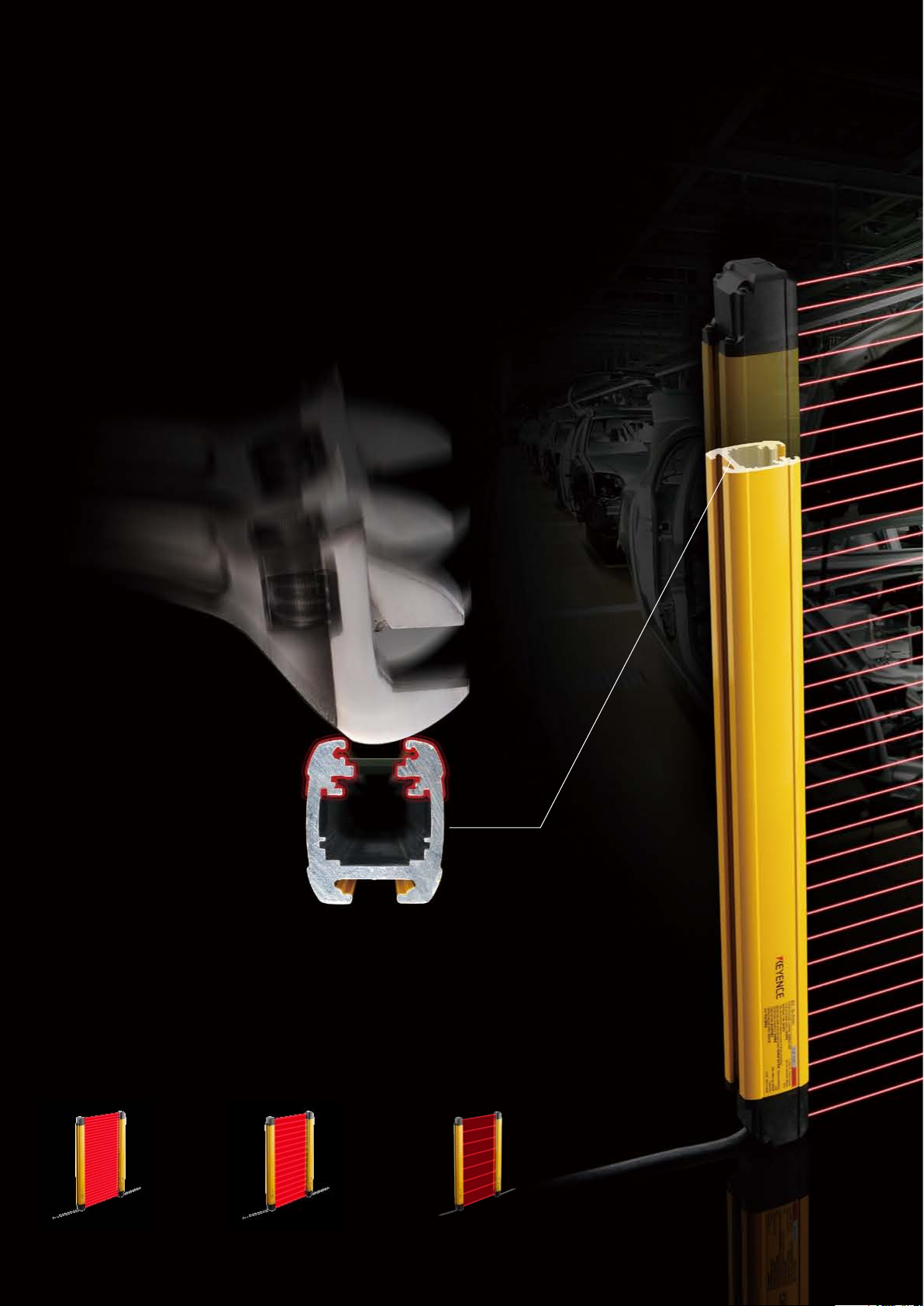
Armoured Protection
What makes a light curtain "robust"?
KEYENCE conducted in-depth research to determine how light curtains are
damaged and learned that the most common cause is damage to the lens
surface when it is scratched, cracked, or otherwise broken due to impact from
parts or tools. In some cases, light curtains have been installed with user-
fabricated protective covers or housing to prevent this damage.
As a result of this research, KEYENCE has designed a light curtain with a
structure that prevents damage from parts or tools by narrowing the exposed
lens area and recessing it in an impact resistant housing.*
* the narrowest lens surface aperture in the industry, according to KEYENCE research as of March, 2012
Strong
Built-in guarding and the narrowest exposed lens surface in the industry.
With its narrow (9 mm wide) and recessed lens surface, the GL-R Series is protected
against impact and resultant damage from parts, tools or operators without the need for
any additional guards or covers. Additionally, the GL-R Series is protected from water and
washdown environments due to its IP65/67 enclosure ratings.
Operating distance
0.2 to 10 m
Detection capability
ø14 mm
GL-RF Series GL-RH Series GL-RL Series
2
Operating distance
0.2 to 15 m
Detection capability
ø25 mm
Operating distance
0.2 to 15 m
Detection capability
ø45 mm
Page 3

Strong × Simple × Smart
Smart
No Dead Zone
Because the rst beam is emitted
10 mm* from each end, the light curtain
can be mounted ush inside of equipment,
eliminating the need for additional
guarding or outside mounting.
*Except GL-RL Series
7-segment display
If an error is ever detected by the light
curtain, the 7-segment display provides
a code that indicates the cause, which
greatly reduces the time required to take
corrective action.
One-line system
Reduce connections to as few as 5 wires
by using this system that eliminates
transmitter wiring completely.
Simple
Reduce installation time with simple wiring and easy-to-use
mounting brackets.
The introduction of the one-line system and optical synchronisation simplies
connections to as few as 5 wires.
Mounting brackets come pre-assembled to provide simple, one-step installation.
3
Page 4

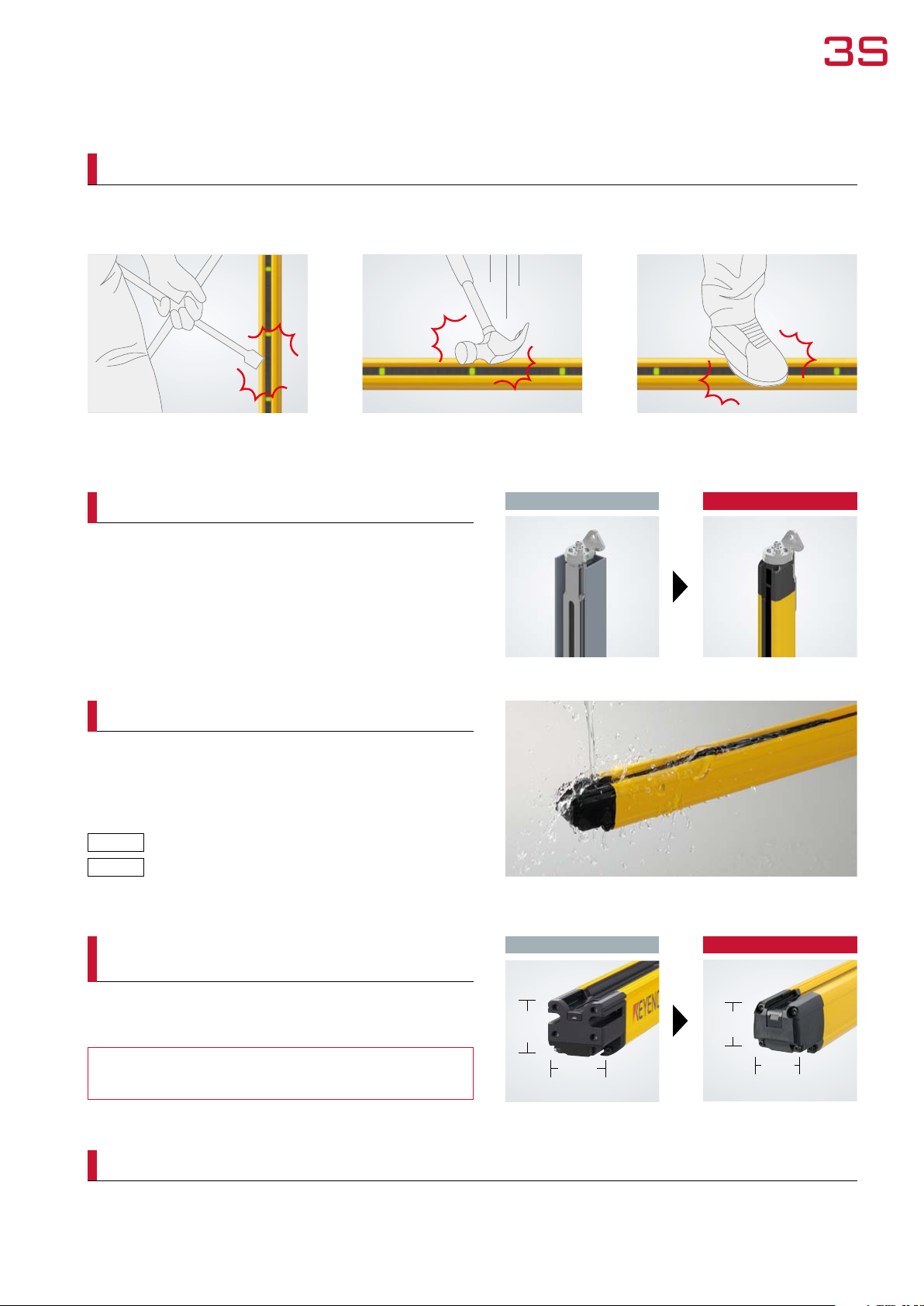
Strong
Securely protects the detection area
Built-in guarding will completely prevent impact to the lens surface by parts or tools of ø17 mm or more.*
Conventional Light Curtain
Narrow
Recessed
*See sp ecications for guarante ed values.
4
Lens surface Lens surface
GL-R Series
Page 5
Strong × Simple × Smart
Thick and robust housing that resists impact
The GL-R Series is designed with a 3 mm thick housing that protects the light curtain body from various forms of impact, such as
dropping equipment or hitting it with tools.*
Hitting
*See sp ecications for guarante ed values.
Dropping Stepping, Kicking
No need for additional guarding
The GL-R Series can be installed and remain protected WITHOUT
the use of additional U-channel type guarding, which simplies
installation and reduces cost.
IP65/IP67 enclosure rating
The GL-R Series housing meets IP65/IP67 enclosure ratings based
on IEC standard, enabling its use in washdown environments
without fear of damage to the light curtain.
IP65
IP67
Water-jet (washdown) resistant
Watertight
Conventional Light Curtain
GL-R Series
Robust, yet slim
(compared to conventional KEYENCE models)
The overall size of the GL-R Series has been reduced to save space
on equipment whilst maintaining KEYENCE's high level of durability.
33% reduction in size compared to the
Conventional Light Curtain
46.5 mm
40 mm
GL-R Series
38 mm
32 mm
conventional model
Long range
The range of the GL-RH and GL-RL Series models have been increased over past models for use in applications requiring protection up
to 15 m.
5
Page 6

Simple
One-line system
•Reduce the number of wires from 18 to 5
•1/3 of the wiring installation time compared to
conventional light curtains
[Recommended for smaller, single operation pieces of equipment]
Simplied wiring
Conventional Light Curtain
The transmitter and receiver had to be routed through the
machine and wired to the control panel.
6
18
wires
One-line system
5
wires
The transmitter receives power from the receiver, meaning that
only the receiver has to be wired to the control panel.
Page 7

Strong × Simple × Smart
Shield
Advantages of the one-line system
Wiring is simplied by connecting the transmitter directly to the receiver, requiring that only the receiver be wired.
1
Reduced risk of mis-wiring due to the reduction in required connections.
2
Conventional Light Curtain
Wiring routed
through the
machine
Example of
wiring
(0V) B lue
(AUX o utput) Red
(Interl ock-reset-read y output) Green
Transmitt er
(Communi cation cable 1)
(+24 V) Brow n
(Wait in put) Purple
(Interl ock mode selecti on input) Pink
Orange
Orange/ black
(Commun ication cable 2)
One-line system
One-line
system
Control panel Control panel
Receiver
Example of
wiring
18
wires
Shield
(+24 V) Brow n
(OSSD 2) White
K2 K1
(0V) B lue
(OSSD1) B lack
(EDM inp ut) Red
(Reset i nput) Yellow
Reduction in
installation time up to
72%
Transmitt er
Receiver
5
wires
(0V) B lue
(+24 V) Brow n
(OSSD1) B lack
R2 R1
(FE) G rey
(OSSD 2) White
Optical synchronisation
[Recommended for larger pieces of equipment or work cells]
•Reduced wiring
Separate transmitter and receiver wiring simplies installation
Conventional Light Curtain
Synchronisation wiring is required. The transmitter and receiver can be wired separately, which
greatly simplies wiring and installation time. Long lengths of
cable are no longer required to be routed through the machine.
Optical synchronisation
7
Page 8
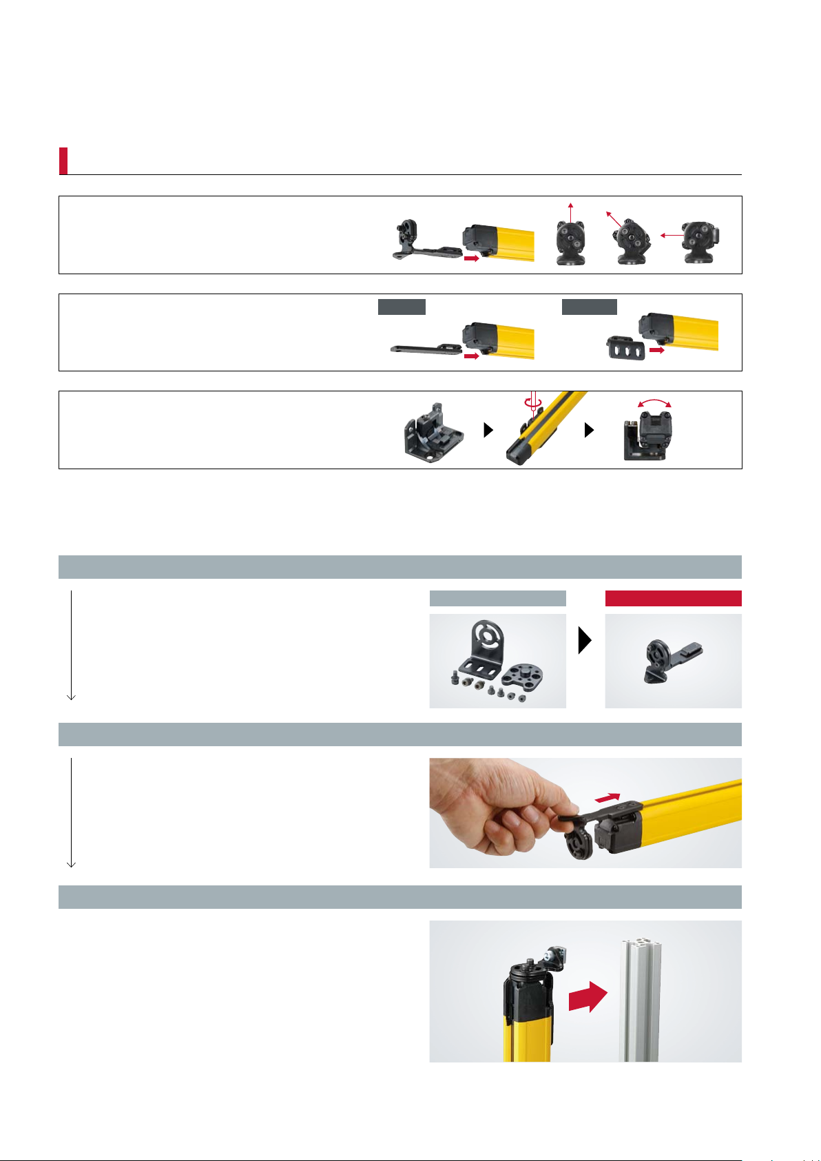
Simple
Quick t brackets
Adjustable angle mounting bracket
Straight / L-shaped mounting bracket
No dead zone mounting bracket
Vertical Horizontal
[ Easy installation ]
1. No assembly required
Traditionally, mounting brackets have required assembly
before installation. However, the GL-R Series brackets
come pre-assembled, so installation is as simple as
sliding them into the mounting track and securing them
to the machine.
2. Insert the bracket into the mounting track
The GL-R Series is designed to simplify mounting by
inserting the brackets into the mounting track and
locking them in place.
3. Mount directly to standard extruded aluminium framework
The GL-R Series mounting brackets have been designed
to attach directly to standard extruded aluminium
framework without the need for any additional hardware.
Conventional brackets
GL-R Series
8
Page 9
Strong × Simple × Smart
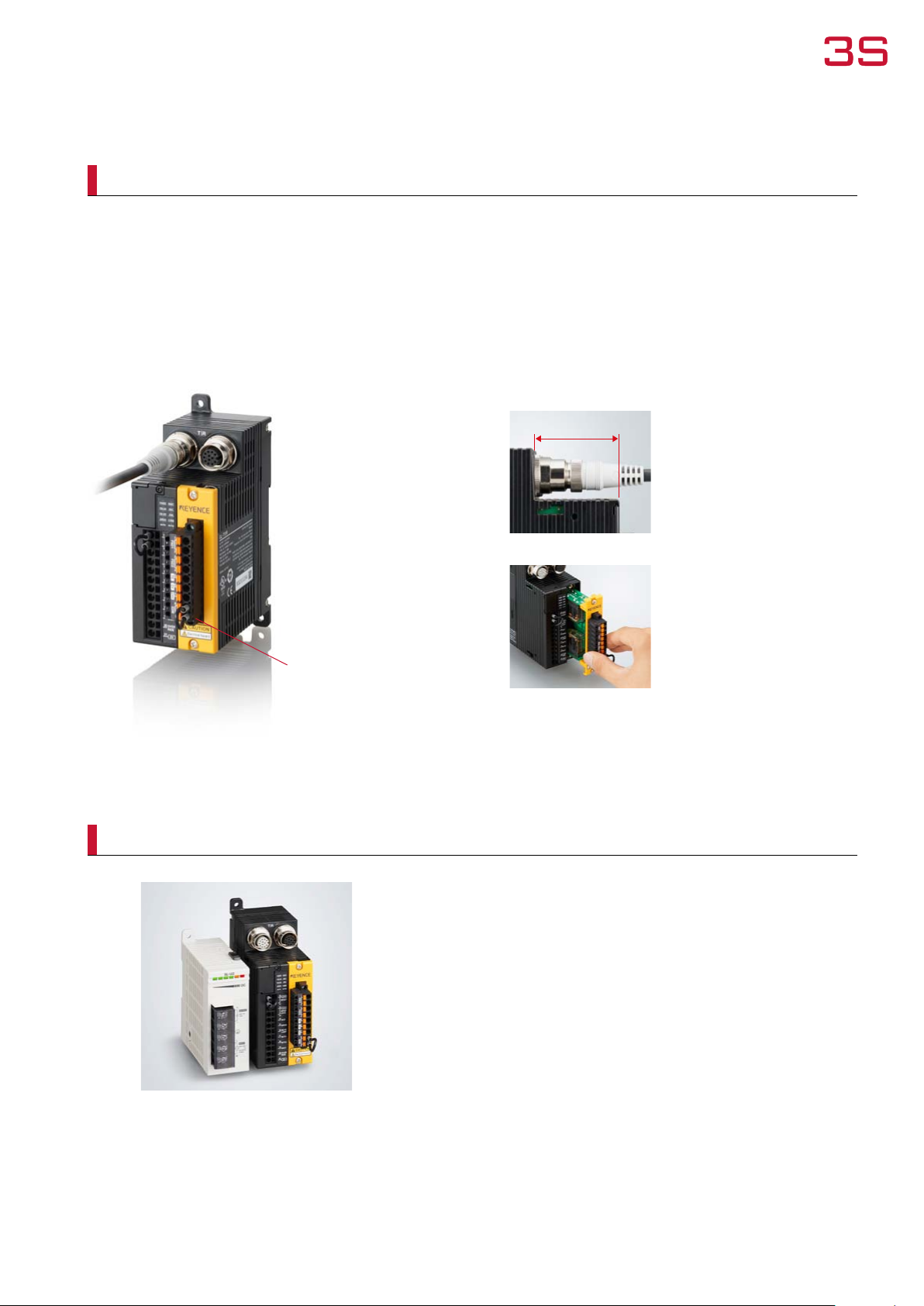
GL-T11R Type4 Quick Disconnect Safety Relay
The GL-T11R combines all of the features necessary to build a Category 4 compatible safety circuit in a single unit.
This makes it possible to dramatically reduce the amount of time and labour required by complex circuit design processes.
It also boasts quick disconnects that simplify the wiring process involved in connecting the light curtain to the relay.
The GL-T11R reduces the need for specialised knowledge about safety circuits.
Quick Disconnect
The safety light curtain is connected
via a quick disconnect, eliminating the
danger of wiring mistakes and reducing
the amount of time and labour required
for wiring.
GL-T11R
Spring type terminal
block
Easy and reliable wiring with no screw
terminals to tighten.
SL-U2 AC Power Supply
Space- saving desi gn
Space-saving
The GL-T11R design ensures that the
connectors do not extend beyond the
unit's footprint, helping to save space
inside the control panel.
Replaceable Relay
The relay board (OP-87682) can be
replaced without removing any wiring,
which eliminates time loss and potential
connection mistakes during rewiring.
* The terminal unit can also be removed
separately.
SL-U2
The SL-U2 dedicated power supply directly connects
to the side of the GL-T11R, providing power to
the entire light curtain setup without the need for
additional wiring.
9
Page 10

Smart
Conventional Light Curtain
No Dead Zone
Because the rst beam is emitted
10 mm* from each end, the light
curtain can be mounted ush
inside of equipment, eliminating
the need for additional guarding or
outside mounting.
*Except GL-RL Ser ies
GL-R
10 mm*
Dead Zone
Dead Zone
7-segment & centre indicators
7-segment display
Errors are displayed as numeric codes, which reduces the amount of
time spent identifying and correcting the problem that was detected by
the GL-R Series.
Centre indicator
These indicators highlight the operational status of the GL-R Series to
the user. The indicators change colour to identify if the light curtain is
clear, interrupted, or in a lockout condition.
Side-Exit Cable
No Dead Zone
10
Page 11

Built-in functionality
Strong × Simple × Smart
Mutual interference prevention
1
Mutual interference between 2 units can be prevented.
Reduced resolution function*
2
This function expands the size of the detection capability.
Up to 2 axes can be disabled.
* In the single zone mode.
For deta ils, refer to GL-R Use r’s Manual.
Centre indicator function control
3
The centre indicators can be turned off to reduce current
consumption.
Built-in series connection ability
The coverage of the GL-R Series can be easily expanded by connecting
additional units in series. All models include this feature as standard.
QD connector
The GL-R Series can easily be connected to a general-purpose, M12 quick
disconnect port or cable.
Corner mirror
Corner mirrors are available to allow 1 set of curtains to cover up to 4 sides
of a machine and reduce the amount of wiring required.
20 mm*
*Except GL-RL Ser ies.
11
Page 12

Advanced Option
PC conguration software
Safety device congurator
MONITORIN G FUNCT I ON
The operation of the GL-R Series can be monitored with
a PC. The status of I/O signals including OSSD outputs,
override inputs, and error conditions can be checked as
well as light intensity. In addition, monitoring the mute
condition will help to easily identify causes of abnormal
operation during the muting setup or operation.
OFF I NFORMAT ION,
ERROR INFO R M ATION,
(free download)
Download site
www.keyence.co.uk/glr_soft
ERROR HISTO RY
OSSD output OFF time, location, and duration can be easily
checked by accessing the OFF information. The Error code,
time of occurrence, and conditions can be checked by
accessing the Error Information. All Error codes and order
of occurrence are saved as Error history records, allowing
the past history to be checked. This allows for easier
troubleshooting and analysis.
OFF infor mation
Error in formation
12
Page 13

Selecting a Safety Light Curtain
Use the following steps to select the optimum GL-R Series components for your application.
ste p
1
ste p
2
ste p
3
ste p
1
Select the light
curtain type
Curtains
GL-RF Series
Detection capability
ø14 mm
Brackets
ste p
2
Select the light
curtain length
ste p
3
Select the
mounting bracket
GL-RH Series
Detection capability
ø25 mm
ste p
4
Select the
cables
*Optional accessories are not required for normal operation.
GL-RL Series
Detection capability
ø45 mm
ste p
5
Select the optional
accessories*
ste p
4
ste p
5
Adjustable angle mounting bracket
GL-RB01
Cables
Optional Accessories
Front protection cover
No dead zone mounting bracket
GL-RB21
Interface unit
Straight mounting bracket
GL-RB11
Corner mirror
SL-M Series
L-shaped mounting bracket
GL-RB12
Dedicated safety relay
for the GL-R Series
GL-T11R
13
Page 14

ste p
1
Select the light curtain type
Select a model according to the distance to the equipment hazard.
Detection capability: ø14 mm
Beam axis pitch of ø10 mm.
Entry detection
To step 2 GL-RF
P.15
Detection capability: ø25 mm
Beam axis pitch of ø20 mm.
Entry detection
To step 2 GL-RH
P.15
Detection capability: ø45 mm
Beam axis pitch of ø40 mm.
Entry/presence detection
To step 2 GL-RL
The required mounting distance fro m the hazard is determined
by the resp onse time and de tection capa bility for the light curtai n
that has b een selecte d. Though the ø25 mm model is used most
freque ntly, if the distance to the hazard is short, select the ø14 mm
model. If the distance to the hazard is long, you can use the
ø45 mm model.
P.15
14
Page 15

ste p
2
Select the light curtain length
If [Detection capability: ø14 mm] was selected in Step 1
GL-RF Series
Model
GL-R23F 23 240 220 244
GL-R31F 31 320 300 324
GL-R39F 39 400 380 404
GL-R47F 47 480 460 484
GL-R55F 55 560 540 564
GL-R63F 63 640 620 644
GL-R71F 71 720 700 724
GL-R79F 79 800 780 804
GL-R87F 87 880 860 884
GL-R95F 95 960 940 964
GL-R103F 103 1040 1020 1044
GL-R111F 111 1120 1100 1124
GL-R119F 119 1200 1180 1204
GL-R127F 127 1280 1260 1284
No. of beam
axes
Total length
(mm)
Detection height
(mm)
Protection height
(mm)
Operating
distance (m)
0.2 to 10
If [Detection capability: ø25 mm] was selected in Step 1
GL-RH Series
Model
GL-R08H 8 160 140 185
GL-R12H 12 240 220 265
GL-R16H 16 320 300 345
GL-R20H 20 400 380 425
GL-R24H 24 480 460 505
GL-R28H 28 560 540 585
GL-R32H 32 640 620 665
GL-R36H 36 720 700 745
GL-R40H 40 800 780 825
GL-R44H 44 880 860 905
GL-R48H 48 960 940 985
GL-R52H 52 1040 1020 1065
GL-R56H 56 1120 1100 1145
GL-R60H 60 1200 1180 1225
GL-R64H 64 1280 1260 1305
GL-R72H 72 1440 1420 1465
GL-R80H 80 1600 1580 1625
GL-R88H 88 1760 1740 1785
GL-R96H 96 1920 1900 1945
No. of beam
axes
If [Detection capability: ø45 mm] was selected in Step 1
GL-RL Series
Model
GL-R04L 4 160 120 205
GL-R06L 6 240 200 285
GL-R08L 8 320 280 365
GL-R10L 10 400 360 445
GL-R12L 12 480 440 525
GL-R14L 14 560 520 605
GL-R16L 16 640 600 685
GL-R18L 18 720 680 765
GL-R20L 20 800 760 845
GL-R22L 22 880 840 925
GL-R24L 24 960 920 1005
GL-R26L 26 1040 1000 1085
GL-R28L 28 1120 1080 1165
GL-R30L 30 1200 1160 1245
GL-R32L 32 1280 1240 1325
No. of beam
axes
Total length
(mm)
Total length
(mm)
Detection height
(mm)
Detection height
(mm)
To step 3
Protection height
(mm)
To step 3
Protection height
(mm)
P.16
Operating
distance (m)
0.2 to 15
P.16
Operating
distance (m)
0.2 to 15
To step 3
P.16
15
Page 16

ste p
3
Select the mounting bracket
Adjustable angle mounting bracket GL-RB01 (incl. 2 pieces)
Side
mounting
45°
mounting
Rear
mounting
45°
mounting
Side
mounting
• By changing the screw positions, it is possible to
adjust the angle of the light curtain by 180°.
If the total length of the GL-R main unit is 1280 mm or longer,
and if mounting it using the Adjustable angle mounting
bracket, also use the antivibration bracket [GL-RB32
(2 pieces/pack)] to prevent vibration.
To step 4
No dead zone mounting bracket GL-RB21 (incl. 2 pieces)
Useful when mounting brackets cannot be used on the top or bottom of the light curtain
• Allows you to rotate the light curtain 90° by
changing the mounting hole. It is also possible to
perform ne-tuning of ±15° from this position.
If the total length of the GL-R main unit is 1280 mm or longer
90° rotation
and if mounting it using the no dead zone mounting bracket,
also use the antivibration bracket [GL-RB32 (2 pieces/pack)]
to prevent vibration.
To step 4
P.17
P.17
Straight mounting bracket GL-RB11 (incl. 2 pieces)
• Simple attachment to standard machine framework.
If the tota l length of the GL-R main unit is 1280 mm or
longer, and if mounting it using th e straight mou nting
bracket, also use the an tivibration bracket [GL-RB31
(2 pieces/pack)] to preve nt vibration .
L-shaped mounting bracket GL-RB12 (incl. 2 pieces)
• Simple attachment to standard machine framework.
If the tota l length of the GL-R main unit is 1280 mm or
longer, and if mounting it using th e L- shaped moun ting
bracket, also use the L-shap ed mounting bracket [GL-RB12
(2 pieces/pack)] to prevent vibration.
To step 4
To step 4
P.17
P.17
16
Page 17

ste p
4
Select the cables
It is possible to select from the following 3 types of wiring systems according to the application.
Select an applicable cable according to the wiring systems listed below.
Cables
• Each model is connected to one cable. Therefore, at least two cables are needed as a system, one for the transmitter and another for the receiver.
• All cables can be used for both the transmitter and receiver.
• The combination of the wiring system and cable determines the functions that can be used. Different types of cables can be used for the transmitter and receiver.
• Make sure that the length of the main unit connection cable and extension cable will be 30 m or less regarding the transmitter and receiver, respectively, when using the
optical/wire synchronisation system.
Make sure that the total length for all cables, which includes the unit connection cable, extension cable, and series connection cable, is 30 m or less when using the one-line
•
system.
Select 1 cable for each transmitter/receiver according to the optimal wiring system.
If multiple functions are necessary, select an 11-core cable.
Wiring system Optical synchronisation system One-line system Wire synchronisation system
Transmitter
Transmitter
Receiver
Wiring diagram
Applicable
Cables
Transmitter
Receiver
5-core cable Series connection cable
5-core cable
11-core cable
5-core cable
11-core cable
Select a unit connection cable or one-line system series connection cable.
If extending the cable, select a connector type.
Shape No. of conductors PNP/NPN Connector Length (m) Model
Unit connection cable
Unit connection cable
(for extension use)
The connector shape for both sides is the same.
5-core
7-core
11-core
5-core
7-core
11-core
Series connection
cable
PNP
NPN
PNP
NPN
PNP
NPN
PNP
NPN GL-RPC03N
PNP
NPN GL-RPC03NS
PNP
NPN GL-RPC03NM
PNP/NPN shared —
— 5 GL-RP5P
— 10 GL-RP10P
— 5 GL-RP5N
— 10 GL-RP10N
— 5 GL-RP5PS
— 10 GL-RP10PS
— 5 GL-RP5NS
— 10 GL-RP10NS
— 5 GL-RP5PM
— 10 GL-RP10PM
— 5 GL-RP5NM
— 10 GL-RP10NM
M12 (5-pin male)
M12 (8-pin male)
M14 (12-pin male)
TransmitterReceiver
7-core cable
11-core cable
7-core cable
11-core cable
0.3
0.08 GL-RS008
0.15 GL-RS015
0.5 GL-RS05
1 GL-RS1
3 GL-RS3
5 GL-RS5
10 GL-RS10
Receiver
GL-RPC03P
GL-RPC03PS
GL-RPC03PM
17
Page 18

ste p
4
Select the cables
For extension
• If using a combination of the unit connection cable (for extension use) and the extension cable,
make sure that they share the same amount of conductors.
Shape No. of conductors PNP/NPN Length (m) Model
5-core
M12 connector
(5-pin female)
Extension cable
7-core
M12 connector
(8-pin female)
11-core
M14 connector
(12-pin female)
PNP/NPN
shared
For series connection
By connecting up to 3 GL-R units in a series, they can function as a single set of light curtains.
• Use a series connection cable to perform series connection.
Shape PNP/NPN Length (m) Model
PNP/NPN
shared
*The connector shape for both sides is the same. There are no regulations for the direction in
which connection is performed.
5 GL-RC5
10 GL-RC10
20 GL-RC20
5 GL-RC5S
10 GL-RC10S
20 GL-RC20S
5 GL-RC5M
10 GL-RC10M
20 GL-RC20M
0.08 GL-RS008
0.15 GL-RS015
0.5 GL-RS05
1 GL-RS1
3 GL-RS3
5 GL-RS5
10 GL-RS10
Installation schematic
Optical synchronisation/
Wire synchronisation system
• Series connection cable
• Unit connection cable
•
Unit connection cable (for extension use)
+ extension cable
*The unit connection cable cannot be installed
on top of the GL-R.
One-line system
18
Page 19

ste p
5
Select the optional accessories
Front protection cover
Select a front protection cover to protect the detection surface as necessary.
Front protection cover
Single side (Transmitter or receiver only) 9.5 m 14.5 m
Both sides (Transmitter and receiver) 9 m 14 m
GL-RF GL-RH GL-RL
Operating distance
Model Applicable GL-R model
GL-RA160 — GL-R08H GL-R04L
GL-RA240 GL-R23F GL-R12H GL-R06L
GL-RA320 GL-R31F GL-R16H GL-R08L
GL-RA400 GL-R39F GL-R20H GL-R10L
GL-RA480 GL-R47F GL-R24H GL-R12L
GL-RA560 GL-R55F GL-R28H GL-R14L
GL-RA640 GL-R63F GL-R32H GL-R16L
GL-RA720 GL-R71F GL-R36H GL-R18L
GL-RA800 GL-R79F GL-R40H GL-R20L
GL-RA880 GL-R87F GL-R44H GL-R22L
Two sets are required to insta ll protection on
both the transmitter and receiver. Refer to the
detecti on distances in the chart when us ing the
front pr otection cove r.
GL-RA960 GL-R95F GL-R48H GL-R24L
GL-RA1040 GL-R103F GL-R52H GL-R26L
GL-RA1120 GL-R111F GL-R56H GL-R28L
GL-RA1200 GL-R119F GL-R60H GL-R30L
GL-RA1280 GL-R127F GL-R64H GL-R32L
GL-RA1440 — GL-R72H —
GL-RA1600 — GL-R80H —
GL-RA1760 — GL-R88H —
GL-RA1920 — GL-R96H —
Interface unit
Optional accessory required to perform conguration and monitoring of the GL-R on a PC.
Model Name
GL-R1UB Interface unit
OP-51580 USB cable 2 m
OP-86941 USB cable 5 m
Corner mirror SL-M Series
By using a corner mirror, it is possible to reduce costs and save time on wiring.
• This is a mirror that reects light from the transmitter within a range of 45° to 95°. Up to 4 mirrors can be used.
For details, see the “SL-M Series instruction manual”.
Model Applicable GL-R model
SL-M12H GL-R23F GL-R08H/GL-R12H GL-R04L/GL-R06L
SL-M16H GL-R31F GL-R16H GL-R08L
SL-M20H GL-R39F GL-R20H GL-R10L
SL-M24H GL-R47F GL-R24H GL-R12L
SL-M28H GL-R55F GL-R28H GL-R14L
SL-M32H GL-R63F GL-R32H GL-R16L
SL-M36H GL-R71F GL-R36H GL-R18L
SL-M40H GL-R79F GL-R40H GL-R20L
SL-M44H GL-R87F GL-R44H GL-R22L
SL-M48H GL-R95F GL-R48H GL-R24L
SL-M52H GL-R103F GL-R52H GL-R26L
SL-M56H GL-R111F GL-R56H GL-R28L
SL-M60H GL-R119F GL-R60H GL-R30L
SL-M64H GL-R127F GL-R64H GL-R32L
*
For eac h single corner mir ror,
the det ection distance will decreas e
by appr oxim atel y 10 %.
SL-M80H
*
SL-M96H
* Newly added to the lineup
— GL-R72H/GL-R80H —
— GL-R88H/GL-R96H —
19
Page 20

ste p
5
Select the optional accessories
GL-T11R Series dedicated relay for the GL-R Series
Dedicated relay for the GL-R Series
Type Model
Safety
GL-T11R
relay
Safety input
Light curtain
1 ch (2 inputs)
(Dedicated for GL-R)
Safety
output
1 channel
(2 outputs)
Other I/O
EDM input, Muting input,
AUX output,
Muting lamp output, etc.
SL- U2
GL- T11R
SL-U2 dedicated power supply for KEYENCE light curtains (Class 2 output)
Dedicated power supply for KEYENCE light curtains
Type Model
Switching type
power supply
SL-U2
Input power
supply voltage
100 to 240 VAC
±10% (50/60 Hz)
Output voltage
24 VDC ±10%
Class 2
Output
capacity
1.8 A 135 VA
Power
consumption
GL-T11R connection cable
• The following cable must be used for connection between the GL-R and GL-T11R.
The system will not operate if other GL-R cables are used to connect the GL-R and GL-T11R.
Shape Length (m) Model
(Common to
transmitter/receiver)
M14 male connector
0.3 GL-RPT03PM
3 GL-RPT3PM
5 GL-RPT5PM
20
Shape Length (m) Model
(Common to
transmitter/receiver)
10 GL-RCT10PM
M14 male connectorM14 female connector
Page 21

SPE CIF I CATI ONS
Model GL-RF GL-RH GL-RL
Beam axis spacing/Lens diameter
Detection capability
Operating distance
Effective aperture angle
Light source
Response time
OSSD operation
Synchronisation between the transmitter and receiver
Light interference prevention function
Output
Max. load current
Control output
(OSSD output)
Supplemental output
(Non-safety-related output)
External input
Power supply
Protection circuit
Environmental resistance
Material
Weight
Approved standards
*1 When the option front protection cover is installed on the one of transmitter or receiver, the Operating distance is shorten by 0.5 m. When the front covers are installed on both of the transmitter and receiver, the Operating distance is shorten by 1.0 m.
*2 When the GL-R is used under surrounding air temperatures between 50 to 55°C, the Maximum load current should not exceed 350 mA.
Residual voltage (during ON)
OFF state voltage
Leakage current
Max. capacitive load
Load wiring resistance
AUX
Error output
Muting lamp output
EDM input
Wait input
Reset input
Muting input 1, 2
Override input
Voltage
Current consumption
Enclosure rating
Overvoltage category
Ambient temperature
Storage ambient temperature
Relative humidity
Storage relative humidity
Ambient light
Vibration
Shock
Main unit case
Upper case/lower case
Front cover
EMC
Safety
EMS
EMI
Short circuit current: Approx. 2.5 mA (Approx. 10 mA with EDM input only)
10 mm / ø4 20 mm / ø5 40 mm / ø5
ø14 mm ø25 mm ø45 mm
1
0.2 to 10 m*
Load current: Max. 50 mA, Residual voltage: Max. 2.5 V (with a cable length of 5 m )
[When using a PNP output cable]
ON voltage: 10 to 30 V
OFF voltage: Open or 0 to 3 V
Reverse current protection, short-circuit protection for each output, surge protection for each output
10 to 55 Hz, 0.7 mm compound amplitude, 20 sweeps each in the X, Y and Z directions
100m/s2 (approx. 10 G), 16 ms pulse in X, Y and Z directions, 1,000 times each axis
Max. ±2.5° (When operating distance is 3 m or more)
Optical synchronisation (Channel 0) or Wire synchronisation: 6.6 to 18.1 ms
Optical synchronisation (Channel A or B): 6.9 to 27.4 ms
Turns on when no interruptions are present in the detection zone
Optical synchronisation or Wire synchronisation (Determined by wiring)
Prevents mutual interference in up to two GL-R systems.
Optical synchronisation: prevented by Channel A and B with setting switch
2 transistor outputs. (PNP or NPN is determined by the cable type)
Transistor outputs (Compatible with both PNP and NPN)
LED lamp (load current: 10 to 230 mA) can be connected
Incandescent lamp: 3,000 lx or less. Sunlight: 20,000 lx or less
EN55011 ClassA, FCC Part15B ClassA, ICES-003 ClassA
IEC61496-1, EN61496-1, UL61496-1 (Type 4 ESPE)
IEC61496-2, EN61496-2, UL61496-2 (Type 4 AOPD)
IEC61508, EN61508 (SIL3), IEC62061, EN62061 (SIL CL3)
Infrared LED (870 nm)
Wire synchronisation: prevented automatically
2
Max. 2.5 V (with a cable length of 5 m )
Max. 2.0 V (with a cable length of 5 m )
Incandescent lamp (24 VDC, 1 to 5.5 W)
24 VDC ±20%, ripple (P-P) 10% or less, Class 2
Transmitter : 37 to 81mA, Receiver : 66 to 91 mA
IEC61496-1, EN61496-1, UL61496-1
EN ISO13849-1:2008 (Category 4, PLe)
500 mA*
Max. 200 µA
2.2 µF
Max. 2.5 Ω
Short circuit current: Approx. 2.5 mA (Approx. 10 mA with EDM input only)
IP65/IP67 (IEC60529)
II
-10 to +55°C (No freezing)
-25 to +60°C (No freezing)
15 to 85% RH (No condensation)
15 to 95% RH
Aluminium
Nylon (GF 30%)
Polycarbonate, SUS304
See p.23
UL508
UL1998
1
0.2 to 15 m*
[When using an NPN output cable]
ON voltage: 0 to 3 V
OFF voltage: Open or 10 V or more
Up to the power voltage
PART DE S CRI PTI ON
Transmitter
Beam centre-line mark
Centre indicators
7-segment display
Function indicators
Setting
switch
Receiver (Back side)
End cover
Connector
for the unit
connection
cable
Setting
switch
Connector for the interface unit
(GL-R1UB)
SETTING SWITCH
Transmitter
Number Details Settings
2
Channel
1
Channel 0
21
(Not applied) (default)
21
Channel A
21
Channel B
Use Channel for light interference
prevention when optical
synchronisation system is applied.
For details, refer to the "GL-R User's
Manual".
Receiver
Number Details Settings
Centre
6
indicator
5
Reduced
resolution
function
4 Reduced resolution (one optical beam) is applied.
(safety
function)
3 Reduced resolution (two optical beams) is applied.
2
Channel
1
ON (Green) when all beam axes are clear (Default)
OFF when all beam axes are clear
Reduced resolution is not applied (Default).
Channel 0
21 543 543 543
(Not applied) (default)
Channel A
21
Channel B
21 66
Use Channel for light interference
prevention when optical
synchronisation system is applied.
For details, refer to the "GL-R User's
Manual".
21
Page 22

IND ICATO RS
Transmitter Receiver
7-segment display
Function indicators
FUNCTION INDICATORS
Name Status Details
POWER (orange)
MUTE (orange)
Light ON Power ON (Transmitter)
Light OFF Power OFF (Transmitter)
Light ON Muted condition or Override condition
Blinking slowly Muting input 1 ON
Light OFF Muting input 1 and 2 OFF
Name State Details
Light in red OSSD OFF
OSSD
(red/green)
INTERLOCK
(Yellow)
•
When opti cal synchronis ation system is app lied, only the “POWE R” indicator turn s ON on the transmit ter.
Light in green OSSD ON
Blinking in green
Light OFF Power OFF (Receiver)
Light ON Interlock condition
Light OFF No interlock or error condition
7-SEGMENT DISPLAY CENTRE INDICATORS
Upon power-up
Wire synchronisation
system or
one-line system
Optical synchronisation system
Channel 0 Channel A Channel B
Beam axis
Centre indicator
(Upper)
Transmitter
Blinking Muting input 2 ON, or muting input 1 and 2 ON
Receiver
Amount of received light is unstable. (Alert output OFF)
Blinking
Interlock reset ready condition (Interlock reset ready output ON)
Centr e indicator (Upper)
indicates whether interruption is pre sent in the
top beam a xis or not. (clear or blocked)
During normal operation
Condition 7-segment display
Apply ing the reduce d resolution function or xe d
blanking function.
Wait inpu t is activated.
Muting i nput 1 ON
Muting i nput 2 ON
Apply ing the muting
function or override
function
Muting i nput 1 and 2 ON
Muted Co ndition
Override input ON
Override condition.
Other t han those above.
*1 When not in the muted condition because conditions for initiation of muting are not met.
*2 When not in the override condition because conditions for initiation of override are not met.
*1
*2
Turn OFF
Error condition
When an error occurs, the OSSD goes to the OFF-state and the GL-R goes
to the error condition. For the 7-segment display in the error condition, refer
to the “instruction manual”.
Centre indicator
(Middle)
Centr e indicator (Middle)
indicates whether the middle axis beams are
interrupted or not.
Centre indicator
(Lower)
Centr e indicator (Lower)
indicates whether interruption is pre sent in the
bottom beam axis or not. (clear or blocked)
Centr e
indic ator
Upper
Middle
Lower
* The cent re indicator on the t ransmitter is O FF when optical syn chronisation sy stem is applied.
Light O FF Light in re d L ight in gree n
Top beam axi s
is blocke d
Top beam axi s
or Botto m
beam a xis is
blocked
Bottom b eam
axis is b locked
Althou gh the top beam ax is is
unbloc ked, the others a re
blocked
Althou gh the top and bott om
beam a xis are unblocke d, the
middle b eams are blocke d
Althou gh the bottom be am
axis is u nblocked, the ot hers
are bloc ked
No inter ruption
is prese nt in
detect ion zone
of the GL-R.
(clear)
Blink ing in
condit ion
red
Error
22
Page 23

RES PON S E T IME (O S SD)
GL-RF
Unit: ms Unit: ms
Response time (OSSD)
Model
GL-R23F
GL-R31F
GL-R39F
GL-R47F
GL-R55F
GL-R63F
GL-R71F
GL-R79F
GL-R87F
GL-R95F
GL-R103F
GL-R111F
GL-R119F
GL-R127F
Wire synchronisation, One-line or
Optical synchronisation system (Channel 0)
ON
OFF OFF ON*1All blocked
6.9 49.2 64.4 9.3 52.7 74.0
7.8 50.5 67.9 10.7 54.8 79.5
8.6 51.8 71.3 12.1 56.9 85.1
9.5 53.1 74.8 13.5 59.0 90.7
10.4 54.3 78.3 14.9 61.1 96.3
11.2 55.6 81.7 16.3 63.2 101.8
12.1 56.9 85.2 17.6 65.3 107.4
13.0 58.2 88.6 19.0 67.4 113.0
13.8 59.5 92.1 20.4 69.4 118.5
14.7 60.8 95.5 21.8 71.5 124.1
15.5 62.1 99.0 23.2 73.6 129.7
16.4 63.4 102.4 24.6 75.7 135.2
17.3 64.7 105.9 26.0 77.8 140.8
18.1 66.0 109.4 27.4 79.9 146.4
ON*
Optical synchronisation system
2
ON OFF OFF ON*1All blocked ON
(Channel A or B)
GL-RL
Unit: ms
Model
GL-R04L
GL-R06L
GL-R08L
GL-R10L
GL-R12L
GL-R14L
GL-R16L
GL-R18L
GL-R20L
GL-R22L
GL-R24L
GL-R26L
GL-R28L
GL-R30L
GL-R32L
*1 If the interruption is present in the detection zone for less than 80 ms, the response time (OFF to ON) will
be 80 ms or more to ensure that the OSSD maintains the OFF state for more than 80 ms.
*2 “All blocked” means the situation where the GL-R operates in optical synchronisation system and the
transmitter and receiver is not synchronised (top and bottom beam axes are both blocked). In this situation,
the response time is longer because the GL-R synchronises the transmitter and receiver rst and then
determines the clear or blocked.
Wire synchronisation, One-line or
Optical synchronisation system (Channel 0)
ON
OFF OFF ON*1All blocked
6.6 48.7 63.1 6.9 49.1 64.2
6.6 48.7 63.1 6.9 49.1 64.2
6.6 48.7 63.1 6.9 49.1 64.2
6.6 48.7 63.1 7.0 49.3 64.9
6.6 48.7 63.1 7.4 49.9 66.3
6.6 48.7 63.1 7.7 50.4 67.7
6.6 48.7 63.1 8.1 50.9 69.1
6.6 48.7 63.1 8.4 51.4 70.5
6.6 48.7 63.1 8.8 52.0 71.9
6.8 49.0 64.0 9.1 52.5 73.3
7.0 49.3 64.9 9.5 53.0 74.7
7.2 49.6 65.7 9.8 53.5 76.1
7.4 50.0 66.6 10.2 54.0 77.5
7.7 50.3 67.5 10.5 54.6 78.9
7.9 50.6 68.3 10.9 55.1 80.2
Response time (OSSD)
Optical synchronisation system
2
ON OFF OFF ON*1All blocked
ON*
(Channel A or B)
ON
GL-RH
Model
2
*
GL-R08H
GL-R12H
GL-R16H
GL-R20H
GL-R24H
GL-R28H
GL-R32H
GL-R36H
GL-R40H
GL-R44H
GL-R48H
GL-R52H
GL-R56H
GL-R60H
GL-R64H
GL-R72H
GL-R80H
GL-R88H
GL-R96H
Wire synchronisation, One-line or
Optical synchronisation system (Channel 0)
ON
OFF OFF ON*1All blocked
6.6 48.7 63.1 6.9 49.1 64.2
6.6 48.7 63.1 7.4 49.9 66.3
6.6 48.7 63.1 8.1 50.9 69.1
6.6 48.7 63.1 8.8 52.0 71.9
7.0 49.3 64.9 9.5 53.0 74.7
7.4 50.0 66.6 10.2 54.0 77.5
7.9 50.6 68.3 10.9 55.1 80.2
8.3 51.3 70.0 11.6 56.1 83.0
8.7 51.9 71.8 12.3 57.2 85.8
9.2 52.6 73.5 12.9 58.2 88.6
9.6 53.2 75.2 13.6 59.3 91.4
10.0 53.9 77.0 14.3 60.3 94.2
10.5 54.5 78.7 15.0 61.4 96.9
10.9 55.2 80.4 15.7 62.4 99.7
11.3 55.8 82.1 16.4 63.4 102.5
12.2 57.1 85.6 17.8 65.5 108.1
13.1 58.4 89.1 19.2 67.6 113.7
13.9 59.7 92.5 20.6 69.7 119.2
14.8 61.0 96.0 22.0 71.8 124.8
Point
• When the GL-R units are connected in series, the response time is
calculated according to the following steps;
1. Sum up the response time of all unit.
2
2. Subtract the following time from the result of previous step.
*
ON to OFF
One sub unit : 2 ms
Two sub unit : 4.2 ms
(When Optical synchronisation system and Channel A or B)
One sub unit : 2.7 ms
Two sub unit : 5.7 ms
OFF to ON
One sub unit : 42 ms
Two sub unit : 84 ms
When connecting the GL-R32H (32 beam axes), GL-R24H (24 beam axes), and
GLR12L (12 beam axes) in series for one-line system, the response time of each
unit is 7.9 ms, 7.0 ms, and 6.6 ms respectively, and the response time (ON to OFF)
is 7.9 ms + 7.0 ms + 6.6 ms - 4.2 ms = 17.3 ms.
The response time (OFF to ON) is 50.6 ms + 49.3 ms + 48.7 ms - 84 ms = 64.6 ms.
• 2.0 m/s is the maximum object detection speed of the GL-R series.
Response time (OSSD)
Optical synchronisation system
2
ON OFF OFF ON*1All blocked
ON*
(Channel A or B)
ON
2
*
CURRENT CONSUMPTION WEIGHT
Unit: mA Unit: mA Unit: mA Unit: g Unit: g Unit: g
Current
consumption
Model
GL-R23F
GL-R31F
GL-R39F
GL-R47F
GL-R55F
GL-R63F
GL-R71F
GL-R79F
GL-R87F
GL-R95F
GL-R103F
GL-R111F
GL-R119F
GL-R127F
* When each input, excluding the EDM input, is turned ON, the current consumption per input increases by 2.5 mA.
(Max.)
Transmitter
50 70
54 71
57 72
60 74
62 75
64 77
66 78
67 80
69 81
71 83
72 84
74 85
76 87
78 89
Receiver
Model
GL-R08H 43 66
GL-R12H 46 68
GL-R16H 50 69
GL-R20H 53 71
GL-R24H 57 72
GL-R28H 59 73
GL-R32H 61 74
GL-R36H 63 75
GL-R40H 65 76
GL-R44H 66 77
GL-R48H 68 79
GL-R52H 69 80
GL-R56H 71 81
GL-R60H 72 82
GL-R64H 73 83
GL-R72H 75 85
GL-R80H 77 87
GL-R88H 79 89
GL-R96H 81 91
Current
consumption
(Max.)
Trans-
Receiver
mitter
Current
consumption
Model
GL-R04L 37 66
GL-R06L 39 67
GL-R08L 41 68
GL-R10L 43 69
GL-R12L 46 70
GL-R14L 48 71
GL-R16L 50 72
GL-R18L 52 73
GL-R20L 54 75
GL-R22L 56 75
GL-R24L 57 76
GL-R26L 59 77
GL-R28L 60 78
GL-R30L 61 79
GL-R32L 62 80
Transmitter
(Max.)
Receiver
Model
GL-R23F 320 330
GL-R31F 430 440
GL-R39F 550 550
GL-R47F 660 670
GL-R55F 780 780
GL-R63F 890 900
GL-R71F 1000 1010
GL-R79F 1200 1200
GL-R87F 1300 1300
GL-R95F 1400 1400
GL-R103F 1500 1500
GL-R111F 1600 1600
GL-R119F 1700 1700
GL-R127F 1800 1900
Weight
Transmitter
Receiver
Model
GL-R08H 210 210
GL-R12H 320 330
GL-R16H 430 440
GL-R20H 550 550
GL-R24H 660 660
GL-R28H 770 770
GL-R32H 880 890
GL-R36H 1000 1000
GL-R40H 1110 1110
GL-R44H 1220 1220
GL-R48H 1330 1340
GL-R52H 1440 1450
GL-R56H 1560 1560
GL-R60H 1670 1680
GL-R64H 1780 1790
GL-R72H 2010 2010
GL-R80H 2230 2240
GL-R88H 2450 2460
GL-R96H 2680 2690
Trans-
mitter
Weight
Receiver
Model
GL-R04L 210 210
GL-R06L 320 330
GL-R08L 430 440
GL-R10L 550 550
GL-R12L 660 660
GL-R14L 770 770
GL-R16L 880 890
GL-R18L 1000 1000
GL-R20L 1110 1110
GL-R22L 1220 1220
GL-R24L 1330 1340
GL-R26L 1440 1450
GL-R28L 1560 1560
GL-R30L 1670 1680
GL-R32L 1780 1790
Transmitter
Weight
Receiver
23
Page 24

FUN CTI O NS AND FE AT URE S
WIRING SYSTEM
Wiring system Optical synchronisation system One-line system Wire synchronisation system
Receiver Receiver
Wiring diagram
Transmitter
Receiver
Transmitter Transmitter
• Wiring is not needed between the transmitter
Advantage
Limitation
Applicable
cables
Wiring system Optical synchronisation system One-line system Wire synchronisation system
Cable
combination
Usable
functions
Transmitter 5-core cable Series connection cable
Receiver
Transmit ter cable 5-core Series connection 7-core 11-core
Receiv er cable 5-core 11-core 5-core 11-core 7-core 11-core 7-core 11-core
OSSD ou tput
AUX (au xiliary) out put
Error o utput
Muting
Part ial muting fun ction
Muting b ank function
Muted c ondition out put
Muting l amp output ( ) ( )
Override function
Inter lock function
Inter lock-reset-r eady output
EDM fun ction ( ) ( ) ( ) ( )
Wait input
Aler t output
Clear/ Block output
Reset in put (for erro r)
Reduce d resolution f unction ( ) ( ) ( ) ( ) ( ) ( ) ( ) ( )
Fixed bl anking funct ion
Channe l conguratio n (Light inter ference prevention function)
Centr e indicator co nguration ( ) ( ) ( ) ( ) ( ) ( ) ( ) ( )
Monitoring functi on
and receiver.
• The Transmitter and the receiver can operate
on different power supplies.
• The input and output functions on the
transmitter are not available.
• All indicators other than “Power” are not
available on the transmitter.
5-core cable
11-core cable
Available with the conguration softwareAvailable without the conguration software
( )
• Simplied wiring.
• The unit connection cable is not needed for
the transmitter.
• The input and output functions on the
transmitter are not available.
• There is a maximum limit for the total length of
cables.
5-core cable
11-core cable
( ) ( ) ( ) ( )
Available without the conguration software. Functionality can be expanded when using the conguration software.
• All functions of the GL-R are available.
• Wiring is needed between the transmitter and
the receiver.
7-core cable
11-core cable
7-core cable
11-core cable
( ) ( )
SERIES CONNECTION
Up to three GL-R units can be serially connected and used as a single light curtain.
INTERLOCK FUNCTION
Interlock is a function that prevents the OSSD from automatically going to the
ON state from an OFF state. You can prevent the unintended start-up and/or the
unintended restart of the machine if an interlock is applied to the GL-R.
24
OSSD
The OSSD is a safety-related control output. It connects to an external device (load),
such as an FSD or MPCE. The GL-R generates self-diagnosis signals on its internal
control circuit to perform diagnostics on the output circuit (OSSD). These signals
periodically force the OSSD into a temporary OFF state when no interruption exists
in the detection zone.
EXTERNAL DEVICE BREAKDOWN DETECTION (EDM FUNCTION)
EDM (External Device Monitoring) is a function of the GL-R that monitors the state
of the control devices which are externally connected to the GL-R. The GL-R can
detect a fault, such as welded contacts on external devices, as long as the EDM
function is activated. This function is available only when connecting the 11-core
cable to the receiver.
Page 25

WIR ING
• Each model is connected to one cable. Therefore, at least two cables are needed as a system, one for the transmitter and another for the
receiver.
Point
CABLE SPECIFICATION CABLE COLOURS AND PIN POSITIONS
Cable length
1
1. Optical synchronisation system, wire synchronisation system
The sum of the length for the unit connection cable and extension cable must be 30 m or
less. This limitation applies separately to the entire transmitter cable setup and the entire
receiver cable setup.
2. One-line system
The sum of the length for all of the unit connection cables, extension cables and series
cables
• All cables can be used for both the transmitter and receiver.
• The combination of the wiring system and cable determines the functions that can be used. Different types of cables can be used for the
transmitter and receiver.
• Be sure to match the numbers of conductors (core wires) when using the unit connection cable for extension use and the extension cable.
Reference
• When the synchronisation wire 1 or 2 is not connected, the GL-R operates in optical
synchronisation system.
• When optical synchronisation system or one-line system is applied, the input and output
functions on the transmitter are not available.
• The functions assigned to the input and output may differ according to the conguration
when setting through the conguration software.
must be 30 m or less.
• “Wiring systems” (page 24)
• Cables must be within the lengths specied. Failure to follow this
specication may cause improper operation of safety functions, and
DANGER
Minimum cable bending radius: 5 mm
2
Identication of connector cables
3
may create a dangerous situation.
• The series connection cable cannot be cut or extended. If the cable
is cut or extended, safety features may not operate properly. Do not
allow this to happen as it is extremely dangerous.
Connector
Connector colour
PNP output type cables or series connection cables : Black connectors
NPN output type cables : Grey connectors
• PNP output type cables and NPN output type cables cannot
Point
be used at the same time (mixed wiring is not possible). One
type of cable must be chosen based on the application.
DIAGRAMS OF THE I/O CIRCUITS
Output circuit (PNP cable)
Main circuit
Input circuit (PNP cable)
Main circuit
Brown
+24V
Black or white
External devices
0V
Blue Blue
Brown
+24V
(Input cable)
Output circuit (NPN cable)
Main circuit
Input circuit (NPN cable)
Main circuit
Brown
+24V
External devices
Black or white
0V
Brown
+24V
(Input cable)
5-core cable
Pin numb er Cable colour
1 Brow n +24V +24V
2 White (Not in use) OSSD2
3 Blue 0V 0V
4 Black (Not in use) OSSD1
5 Grey FE FE
When the transmitter is
connected
Reference
M12 connector male pin assignment M12 connector female pin assignment
Name
When the receiver is
connected
7-core cable
Pin numb er Cable colour
1 White Wait i nput OSSD2
2 — (Not in use) (Not in use)
3 Black Error output OSSD1
4 Brow n +24V +24V
5 Orange Synchronisation 1 (RS-485 +) Synchronisation 1 (RS-485 +)
6 Or ange/black Synchronisation 2 (RS-485 -) Synchronisation 2 (RS-485 -)
7 Blu e 0V 0V
8 Grey FE FE
When the transmitter is
connected
Reference
M12 connector male pin assignment M12 connector female pin assignment
Name
When the receiver is
connected
11-core cable
Pin numb er Cable colour
1 White Wait i nput OSSD2
2 — (Not in use) (Not in use)
3 Black Error output OSSD1
4 Yellow Override input RESET input
5 Orange Synchronisation 1 (RS-485 +) Synchronisation 1 (RS-485 +)
6 Or ange/black Synchronisation 2 (RS-485 -) Synchronisation 2 (RS-485 -)
7 Blu e 0V 0V
8 Red Muting lamp output AUX output
9 R ed/black Muting input 2 EDM input
10 Brow n +24V +24V
11 Pink Muting input 1 Interlock selection input
12 Grey FE FE
When the transmitter is
connected
Reference
Name
When the receiver is
connected
Blue
0V
Blue
0V
M14 connector male pin assignment M14 connector female pin assignment
25
Page 26

(FE) Grey
(FE) Grey
(FE) Grey
(FE) Grey
EXA MPL E S O F W IRI N G
• Unused I/O cables should be individually insulated.
• The functions assigned to the input and output may differ according to the conguration when conguring through the conguration software.
NOTICE
SIGNAL MEANING
R1, R2 External device (safety PLC, safety relay unit, etc.)
K1, K2 External device (Force guided relay, magnet connector, etc.)
K3 Solid state connector*
S1 Switch used for reset input
S2 Switch used for wait input*
S3 Switch used for override input
For more information, see the “GL-R Series user’s Manual”.
• The Grey cable (FE) is electrically connected to the main unit case.
• The main unit case and a power-supply line are connected by a capacitors 3kV 100pF.
1
1
S4 to 6 Switch used for muting bank inputs
L1 Muting lamp (Incandescent lamp or LED lamp)
P1, P2 Muting device (Self-contained photoelectric sensors, etc.)
M 3-phase motor
PLC For NON SAFETY-RELATED system control use*
*1 T hese ar e NON S AFETY-REL ATED c ompone nts.
1
OPTICAL SYNCHRONISATION SYSTEM
Transmitter : 5-core cable, Receiver: 5-core cable
(1) PNP output cable
(2) NPN output cable
Transmitter
(0V) Blue
(+24 V) B rown
(Not in use) Black
(Not in use) White
Transmitter
(0V) Blue
(+24 V) B rown
(Not in use) Black
(Not in use) White
Receiver
(0V) Blue
(FE) Grey
(OSSD1) Black
(OSSD2) White
(+24 V) B rown
R1 R2
Receiver
(0V) Blue
(FE) Grey
(OSSD1) Black
(OSSD2) White
(+24 V) B rown
R1 R2
Transmitter : 5-core cable, Receiver: 11-core cable
Uses EDM input and the interlock function
(1) PNP output cable
Transmitter
Receiver
ONE-LINE SYSTEM
• The series connection cable must be used to connect the transmitter and
receiver.
• The unit connection cable is not needed for the transmitter.
• The wiring when using an 11-core cable with the receiver is the same as the
optical synchronisation system wiring.
Transmitter : Series connection cable, Receiver: 5-core cable
(1) PNP output cable
(2) NPN output cable
Transmitter
Transmitter
(+24V) Brown
(+24V) Brown
Receiver
(OSSD1) Black
(OSSD2) White
R1 R2
Receiver
(OSSD1) Black
(OSSD2) White
R1 R2
(0V) Blue
(0V) Blue
(FE) Grey
(FE) Grey
(2) NPN output cable
(FE) Grey
(0V) Blue
(Not in use) White
K1K2
M
Transmitter
(0V) Blue
(Not in use) White
K1K2
M
Orange (Not in use)
Orange/Black (Not in use)
(+24V) Brown
(Not in use) Black
K3
Orange (Not in use)
Orange/Black (Not in use)
(+24V) Brown
(Not in use) Black
K3
(+24V) Brown
(+24V) Brown
(OSSD1) Black
(OSSD2) White
K2K1
OUT
PLC
Receiver
(OSSD1) Black
(OSSD2) White
K2K1
OUT IN
PLC
(0V) Blue
(0V) Blue
(FE) Grey
(AUX output) Red
IN
(FE) Grey
(AUX output) Red
(EDM input) Red/Black
(Reset input) Yellow
K1
K2
(Interlock mode selection input) Pink
S1
(EDM input) Red/Black
K1
(Reset input) Yellow
K2
S1
(Interlock mode selection input) Pink
WIRE SYNCHRONISATION SYSTEM
Transmitter : 7-core cable, Receiver: 7-core cable
(1) PNP output cable
(2) NPN output cable
(FE) Grey
(0V) Blue
(0V) Blue
Transmitter
Orange (Synchronisation 1)
Orange/Black (Synchronisation 2)
(+24V) Brown
(Wait input) White
(Error output) Black
S2
PLC
Transmitter
Orange (Synchronisation 1)
Orange/Black (Synchronisation 2)
(+24V) Brown
(Wait input) White
(Error output) Black
S2
PLC
(+24V) Brown
(+24V) Brown
Receiver
(OSSD1) Black
(OSSD2) White
R1 R2
Receiver
(OSSD1) Black
(OSSD2) White
R1 R2
(0V) Blue
(0V) Blue
(FE) Grey
(FE) Grey
26
Page 27

SPE CIF I CATI ONS [GL -T1 1R]
Model
Applicable model
Relay output FSD1,2
Response
time
ONOFF
OFFON
Life-span Electrical life-span
AUX out put
Non-sa fety
output
Error ou tput
Muting l amp output
EDM inpu t
Exte rnal
input
Power sup ply
Wait inpu t
Reset inp ut
Muting in put 1, 2
Overri de input
Power sup ply
voltag e
Curren t
consump tion
Enclosu re rating
Pollut ion degree
Overvo ltage
catego ry
Ambien t
temper ature
Enviro nmental
resist ance
Storag e ambient
temper ature
Relati ve humidity
Storag e relative
humidit y
Altit ude
Vibra tion
Shock
Materi al Main uni t case
Weight
EMS
EMC
Appro ved
stand ards
*1 The output operation is the same as that when the PNP output type cable is used.
EMI
Safet y
250 VAC 6 A 30 VDC 6 A (Resistance load)
240 VAC 2 A (COSø=0.3) (Inductive load)
24 VDC 1 A (COSø=0.3) (Inductive load)
100,000 cycles or more with 250 VAC 6 A resistance load
(open/close frequency: 20 times/minute)
100,000 cycles or more with 30 VDC 6 A resistance load
(open/close frequency: 20 times/minute)
500,000 cycles or more with 250 VAC 1 A resistance load
(open/close frequency: 30 times/minute)
500,000 cycles or more with 30 VDC 1 A resistance load
(open/close frequency: 30 times/minute)
AC15: 100,000 cycles or more with 240 VAC 2 A inductive load
(open/close frequency: 20 times/minute, cosø = 0.3)
DC13: 100,000 cycles or more with 24 VDC 1 A inductive load
(open/close frequency: 20 times/minute, L/R = 48 ms)
Transistor output (PNP/NPN input device can be connected.) *
50 mA max., residual voltage 2.5 V max.
(When the cable between the GL-R and GL-T11R is 5 m)
Incandescent lamp (24 VDC, 1 to 5.5 W)
LED lamp (load current: 10 to 230 mA) can be connected.
ON voltage: [Power supply voltage - 5 V] to [Power supply voltage]
24 VDC ±10%, ripple (P-P) 10% or less, Class 2
Must be installed within a control panel rated at IP54 or higher.
20 sweeps each in the X, Y and Z directions
100m/s2 (approx. 10 G), 16 ms pulse in
X, Y and Z directions, 1,000 times each axis
EN55011 ClassA, FCC Part15B ClassA, ICES-003 ClassA
EN61496-1, UL61496-1, IEC61496-1 (Type4 ESPE)
EN ISO13849-1 : 2008 (Category4, PLe)
GL-T11R
GL-R Series
GL-R +10 ms
GL-R +32 ms
OFF voltage: Open or 0 to 3 V
Short circuit current: Approx. 2.5 mA
(Approx. 10 mA with EDM input only)
100 mA max. (24 VDC, GL-T11R only)
IP20 (IEC60529)
2
III
-10 to +55°C (No freezing)
-25 to +60°C (No freezing)
15 to 85% RH (No condensation)
15 to 95% RH
2,000 m or less
10 to 55 Hz
0.7 mm compound amplitude
Polycarbonate
Approx. 310 g
EN61496-1, UL61496-1, IEC61496-1
UL508, EN50178
Model
Type
Input po wer supply volta ge
Overvo ltage catego ry
Outpu t voltage
Ripple /noise
Outpu t capacity
Enviro nmental
resist ance
Pollut ion degree
Withs tand voltage
Vibra tion
1
Shock
Insula tion resistan ce
Power con sumption
Moment ary interru ption
Weight
Appro ved
stand ards
Ambien t
temper ature
Relati ve humidity
EMC
Safet y
1 minute (across all external terminals and case)
20 sweeps each in the X, Y and Z directions
100m/s2 (approx. 10 G), 16 ms pulse in
X, Y and Z directions, 1,000 times each axis
(With 500 VDC megohmmeter across
FCC Part15 Class A, ICES-003 Class A
EN60950-1, EN50178, UL60950-1, UL508
SL-U2
Switching type
100 to 240 VAC ±10% (50/60 Hz)
35 to 85% RH (No condensation)
0.7 mm compound amplitude
all external terminals and case)
EN61000-6-2, EN55011 Class A,
II
24 VDC ±10%, Class 2
240 mVp-p max.
1.8 A
-10 to +55°C (No freezing)
2
1500 VAC
10 to 55 Hz
50 MΩ or more
135 VA
10 ms max.
Approx. 240 g
27
Page 28

WIR ING [GL -T1 1R]
No.
1
2
3
4
5
6
7
8
9
10
11
12
Name
OSSD2
Not in use
OSSD1
Reset input
Synchronisation 1 (RS485+)
Synchronisation 2 (RS485–)
24 V
AUX output
EDM input
0 V
Interlock selection input
FE
No.
1
2
3
4
5
6
7
8
9
10
11
12
Name
Wait input
Not in use
Override input
Error output
Synchronisation 1 (RS485+)
Synchronisation 2 (RS485–)
24 V
Muting lamp output
Muting input 2
0 V
Muting input 1
FE
No.
1
2
3
4
5
6
7
8
9
Name
FE
0 V
24 V (Input)
EDM input (24 V)
EDM input
FSD1
FSD2
No.
10
11
12
13
14
15
16
17
18
19
20
21
Name
Reset input (24 V)
Reset input
Interlock selection input (24 V)
Interlock selection input
AUX output
Error output
Muting lamp output
Muting input 1
Muting input 2
Wait input
Override input
0 V
K1
K1
K2
K2
GL-R main unit Relay unit
Receiver Relay output terminals
Transmitter
Signal input/output terminals
Relay output terminals
Internal circuit diagram
Wiring example
The wiring example shown here assumes the case of the following settings:
• Interlock function: Enabled (Manual reset mode)
• EDM function: Enabled
• Muting function: Enabled
FSD1
FSD2
FE
0 V *
24 V (Input) *
EDM input (24 V) *
EDM input *
Name
1
1
2
2
No.
F1
1
2
F2
3
4
5
6
7
8
9
K3
K4
K3
K4
K4
K3
M
Name
3
Black
Blue
P1
Brown
Black
Brown
P2
Blue
3
No.
10
11
12
13
14
15
16
17
18
19
20
21
PLC IN
S1
L1
S2
S3
28
Signal input/output terminals
Reset input (24 V) *
Reset input *
Interlock selection input (24 V)
Interlock selection input
AUX output
Error output
Muting lamp output
Muting input 1
Muting input 2
Wait input
Override input
0 V
F1, F2 Fuse
K3, K4 External device (Magnet contactor, etc.)
S1 Switch for reset (N.O.)
S2 Switch for wait input (N.O.)
S3 Switch for override (N.O.)
L1 Muting lamp (Incandescent lamp or LED lamp)
P1, P2 Muting device
(PZ Series self-contained photoelectric sensor <PNP
output>, etc.)
M 3-phase motor
PLC
For monitoring use. This is a NON-SAFETY RELATED system.
S2 and PLC are NON-SAFETY RELATED systems.
*1 No. 6 and No. 7 do not need to be wired when the SL-U2 is connected.
*2 If it is not necessary to perform error detection for K3 and K4 (when EDM
input is not used), use the shorting bar between No. 8 and No.9.
*3 In the auto reset mode, use the shorting bar between No. 10 and No.11.
To release the error condition of a GL-R through the reset input, connect a
N.C. switch.
Points
• Depending on the settings of the “Safety Device
Congurator” PC setting software, each function is
switched to a different function. When the settings are
changed, check the wiring referring to the internal circuit
diagram in the previous section.
• The total electric current supplied from each 24 V
terminal of the GL-T11R must be 95 mA or less.
Page 29

Detection capability
DIM ENS I ONS
GL-R (GL-RF/RH/RL) MAIN UNIT
Transmitter/Receiver
Unit: mm
GL-RF UNIT VARIATION
Length
240 mm to 1280 mm
38
A B C
G
Interface unit
connector
(Only receiver)
GL-RH UNIT VARIATION
Length
160 mm to 1920 mm
32
F
E
When the total length of the GL-R main unit becomes 1280 mm
or longer, attach an antivibration bracket to the centre of the
length of the GL-R (Distance G in the figure).
Mounting bracket being used Antivibration bracket to use
Note
D
32.9
10
Setting switch
Adjustable angle mounting bracket
No dead zone mounting bracket
Straight mounting bracket
L-shaped mounting bracket L-shaped mounting bracket
Antivibration bracket for adjustable
angle mounting bracket
Antivibration bracket for straight
mounting bracket
GL-RL UNIT VARIATION
Length
160 mm to 1280 mm
Max. length
1920 mm
Min. length
240 mm
23 beam axes 127 beam axes
Max. length
1280 mm
Min. length
160 mm
8 beam axes 4 beam axes96 beam axes 32 beam axes
Understanding the model name Meaning of each item
Beam centre-line mark
GL-R 12 H
1 2 3
1
Series name
2
Number of beam axes: 2 or 3 digit number.
Ex.: 08 = 8 axes, 64 = 64 axes
3
Detection capability: F: ø14 mm detection type,
H: ø25 mm detection type,
L : ø45 mm detection type
The m ain uni t includ es both transmit ter and receiver as one set.
a: Beam axis spacing
b: Beam axis diameter
c: Detection capability
Length
Min. length
160 mm
Detection height
Max. length
1280 mm
b
a
Protection height
c
29
Page 30

DIM ENS I ONS
Dimensions for units A-G
Model No. of axes Length Detection height Protection height Beam axis pitch
GL-R23F
GL-R31F
GL-R39F
GL-R47F
GL-R55F
GL-R63F
GL-R71F
GL-R79F
GL-R87F
GL-R95F
GL-R103F
GL-R111F
GL-R119F
GL-R127F
Model No. of axes Length Detection height Protection height Beam axis pitch
GL-R08H
GL-R12H
GL-R16H
GL-R20H
GL-R24H
GL-R28H
GL-R32H
GL-R36H
GL-R40H
GL-R44H
GL-R48H
GL-R52H
GL-R56H
GL-R60H
GL-R64H
GL-R72H
GL-R80H
GL-R88H
GL-R96H
23 240 220 244
31 320 300 324 160
39 400 380 404 200
47 480 460 484 240
55 560 540 564 280
63 640 620 644 320
71 720 700 724 360
79 800 780 804 400
87 880 860 884 440
95 960 940 964 480
103 1040 1020 1044 520
111 1120 1100 1124 560
119 1200 1180 1204 600
127 1280 1260 1284 640
8 160 140 185
12 240 220 265 120
16 320 300 345 160
20 400 380 425 200
24 480 460 505 240
28 560 540 585 280
32 640 620 665 320
36 720 700 745 360
40 800 780 825 400
44 880 860 905 440
48 960 940 985 480
52 1040 1020 1065 520
56 1120 1100 1145 560
60 1200 1180 1225 600
64 1280 1260 1305 640
72 1440 1420 1465 720
80 1600 1580 1625 800
88 1760 1740 1785 880
96 1920 1900 1945 960
10 10 12
20 10 22.5
Unit: mm
120
Unit: mm
80
30
Model No. of axes Length Detection height Protection height Beam axis pitch
GL-R04L
GL-R06L
GL-R08L
GL-R10L
GL-R12L
GL-R14L
GL-R16L
GL-R18L
GL-R20L
GL-R22L
GL-R24L
GL-R26L
GL-R28L
GL-R30L
GL-R32L
4 160 120 205
6 240 200 285 120
8 320 280 365 160
10 400 360 445 200
12 480 440 525 240
14 560 520 605 280
16 640 600 685 320
18 720 680 765 360
20 800 760 845 400
22 880 840 925 440
24 960 920 1005 480
26 1040 1000 1085 520
28 1120 1080 1165 560
30 1200 1160 1245 600
32 1280 1240 1325 640
40 30 42.5
Unit: mm
80
Page 31

DIM ENS I ONS
17.2
Mounting bracket
Adjustable angle mounting bracket
GL-RB0 1
When mounted on GL-R
Back mounted state
12
7
Unit: mm
Side mounted state
12
7
4
48
ø6.2
13
34
5
4
32
No dead zone mounting bracket
GL-RB2 1
56.5
8.3
6.3
30.8
8.3
6.3
13
30.8
43.3
8
15
25.1
8.1
Material: SPHC
15
56.5
96.6
95.1
When mounted on GL-R
74.5
48
50
Back mounted state
50
40.8
12
30.8
14.8
4
46.8
ø6.2
9
15
17
25.1
32
ø6.2
9
15
17
25.1
43
Side mounted state
12
74.5
56.5
(16.5)
8.3
6.3
15.3
53.7
47.3
74.5
(16.5)
53.7
15.3
50
47.3
40.8
12
Material: Zinc die-cast
Straight mounting bracket
GL-RB1 1
10.2
5
54.5
13
8
34
5
96.5
95
6.2
8
9.2
19
Material: SPHC
When mounted on GL-R
Mounted state
95
36.5
6.2
5
9.2
43
10
18
19
31
Page 32

38
25
DIM ENS I ONS
Antivibration bracket
L-shaped mounting bracket
GL-RB1 2
When mounted on GL-R
Unit: mm
Mounted state
2 x R4
30
50
6.2
10.2
5
Interface unit
GL-R1U B
14.9
5
5.2
34 35
13
18
R2
R4
3 x R3
Material: SPHC
28
11
50
(29)
34
30
10.2
28
25
5
6.2
54
52.9
63
5
GL-R
Length
34
Front protection cover
Mounted state
GL-RA
Mounted state
41.9
12.9
33.8
19.2
GL-R
32.9
Length
See p. 19 for the details
CAD DATA Download:
Front protection cover
length
www.keyence.co.uk/CADG
31.8
49.6
1.1
43.1
16.3
24.9
10.1
24.9
43.1
69.8
2.1
1.5
2.7
32
Page 33

DIM ENS I ONS
(46.8)
Antivibration bracket
Unit: mm
Antivibration bracket for the straight mounting bracket
GL-RB3 1
30
Antivi brat ion bracket for the adjust able angle moun ting bracke t
GL-RB3 2
12
70
40
C1.5
10.5
Material: EPDM
R0.5
6*
*5 mm: when mounting
Mounted state Mounted state
38
50.5
46.8
43
5
70
Half
the length
12.5
4
16
30.8
28.1
10.7
64
83
48 40
6 × R2
Spot facing 2 × ø13.5
Depth 2
46.8
4
2.7
46.8
14.8
83
40
48
Half
the length
39
2 × ø6.2
18.2
12.5
38.8
50.5
12.5
83
48
40
Material: SPHC, EPDM
Half
the length
46.8
14.8
4
32
GL-T11R Series dedicated relay for the GL-R
GL-T11 R
(112)
3.5
49.8
35.9
(100.7)
83.8
(16)
2-ø4.2
124
48
11
23
2.7
38.8
2.7
38.8
SL-U2 dedicated power supply for KEYENCE light curtains (Class 2 output)
SL-U2
35
11
24
23
135
2-ø4.2
100
(96.6)
25.8
35.9
111
37
11
33
Page 34

Related product
GLR-WW-C2-GB 1015-3 600B53
Copyright (c) 2012 KEYENCE CORPORATION. All rights reserved.
www.keyence.com
Highly-Visible Safety Light Curtain
SL-V Series
Type4 SIL3
Various lineup
SL-VF Ser ies
Detection capability
ø14 mm
SL-VH Ser ies
Detection capability
ø25 mm
World's first
“Highly-Visible Indicator” will make the presence of a light
curtain seen easily, which will prevent accidental light shielding.
In addition, lighting and blinking of the indicator will help
understand the state of the light curtain easily.
Sup er Heavy Duty
Highly-Visible Indicator
SL-VFM Se rie s
Detection capability
ø14 mm
SL-VHM Se rie s
Detection capability
ø25 mm
 Loading...