Kenwood th f7a e schematic
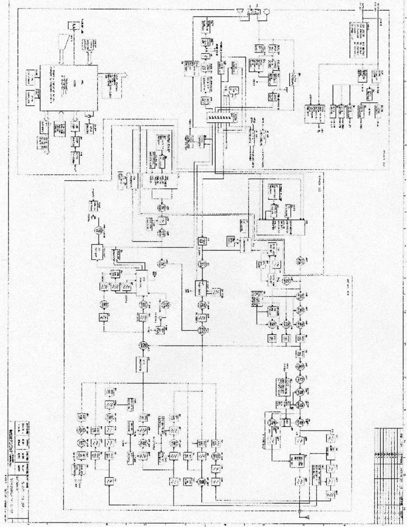
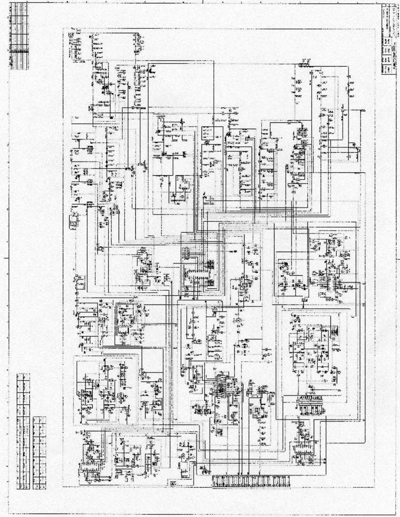
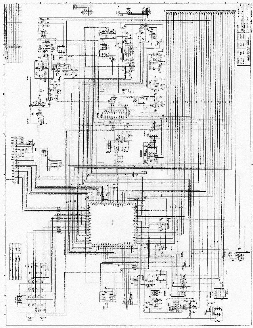
Kenwood TH-F6A/TH-F7E
Protocol Specification
Version 1.4
Warranty, Disclaimer, Assumption of Risk, and Indemnification
ALL DATA AND INFORMATION PROVIDED IN THIS DOCUMENT IS FOR INFORMATIONAL
PURPOSES ONLY AND IS AN EXPRESSION OF FREE SPEECH.
Definition: The term "person" as used in this section includes not only a natural person but also any entity, (including natural persons). The term “author” is the person or persons who wrote this document. The term “reader” is the user of this document.
NO WARRANTIES: TO THE EXTENT PERMITTED BY APPLICABLE LAW, NEITHER THE AUTHOR OF THIS DOCUMENT, NOR ANY PERSON, EITHER EXPRESSLY OR IMPLICITLY, WARRANTS ANY ASPECT OF THIS DOCUMENT, INCLUDING ANY OUTPUT OR RESULTS OF THE USE OF THIS DOCUMENT. UNLESS AGREED TO IN WRITING. THIS DOCUMENT IS BEING PROVIDED "AS IS", WITHOUT ANY WARRANTY OF ANY TYPE OR NATURE, EITHER EXPRESS OR IMPLIED, INCLUDING, BUT NOT LIMITED TO, THE IMPLIED WARRANTIES OF MERCHANTABILITY AND FITNESS FOR A PARTICULAR PURPOSE, AND ANY WARRANTY THAT THIS DOCUMENT IS FREE FROM DEFECTS.
ASSUMPTION OF RISK: THE RISK OF ANY AND ALL LOSS, DAMAGE, OR UNSATISFACTORY PERFORMANCE DOCUMENT RESTS WITH THE READER. TO THE EXTENT PERMITTED BY LAW, NEITHER THE AUTHOR OF THIS DOCUMENT, NOR ANY PERSON EITHER EXPRESSLY OR IMPLICITLY, MAKES ANY REPRESENTATION OR WARRANTY REGARDING THE APPROPRIATENESS OF THE USE, OUTPUT, OR RESULTS OF THE USE OF THIS DOCUMENT IN TERMS OF ITS CORRECTNESS, ACCURACY, RELIABILITY, BEING CURRENT OR OTHERWISE. NOR DO THEY HAVE ANY OBLIGATION TO CORRECT ERRORS, MAKE CHANGES, SUPPORT THIS DOCUMENT, DISTRIBUTE UPDATES, OR PROVIDE NOTIFICATION OF ANY ERROR OR DEFECT, KNOWN OR UNKNOWN. IF THE READER RELIES UPON THIS DOCUMENT, THE READER DOES SO AT THEIR OWN RISK, AND THE READER ASSUMES THE RESPONSIBILITY FOR THE RESULTS. SHOULD THIS DOCUMENT PROVE DEFECTIVE OR INCORRECT, THE READER ASSUMES THE COST OF ALL LOSSES, INCLUDING, BUT NOT LIMITED TO, ANY NECESSARY SERVICING, REPAIR OR CORRECTION OF ANY PROPERTY INVOLVED.
DISCLAIMER: IN NO EVENT, UNLESS REQUIRED BY APPLICABLE LAW OR AGREED TO IN WRITING, SHALL THE AUTHOR, OR ANY PERSON, OTHER THAN THE READER, BE LIABLE FOR ANY LOSS, EXPENSE OR DAMAGE, OF ANY TYPE OR NATURE ARISING OUT OF THE USE OF, OR INABILITY TO USE THIS DOCUMENT, INCLUDING, BUT NOT LIMITED TO, CLAIMS, SUITS OR CAUSES OF ACTION INVOLVING ALLEGED INFRINGEMENT OF COPYRIGHTS, PATENTS, TRADEMARKS, TRADE SECRETS, OR UNFAIR COMPETITION.
“REVERSE ENGINEERING” OR VIOLATING THE COPYRIGHT OF KENWOOD COMMUNICATIONS CORPORATION OR ANY OTHER THIRD PARTY DID NOT OCCUR IN OBTAINING THE INFORMATION IN THIS DOCUMENT. THE INFORMATION OBTAINED FOR THIS DOCUMENT WAS DISCOVERED BY TRYING ALL ONE, TWO, THREE, AND FOUR LETTER ALPHABETIC COMMANDS SENT TO THE TRANSCEIVER THROUGH A TERMINAL PROGRAM AND LOOKING AT AND EVALUATING THE RESPONSE FROM THE TRANSCEIVER OR BY EXAMINING THE TEXT FILE CREATED BY THE KENWOOD SOFTWARE. THE SCREEN SHOTS OF KENWOOD CORPORATION’S SOFTWARE VIOLATES NO COPYRIGHT SINCE THESE SCREEN SHOTS ARE FOUND IN THE PUBLIC DOMAIN. IT IS THE AUTHOR’S OPINION AS TO WHAT COMMANDS ARE USED TO OBTAIN INFORMATION IN THE KENWOOD SOFTWARE.
INDEMNIFICATION: TO THE EXTEND PERMITTED BY LAW THROUGH THIS AGREEMENT, THE READER AGREES TO INDEMNIFY AND HOLD HARMLESS THE AUTHOR OF THIS DOCUMENT, OR ANY PERSON FROM AND AGAINST ALL CLAIMS, LIABILITIES, LOSSES, CAUSES OF ACTION, DAMAGES, JUDGMENTS, AND EXPENSES, INCLUDING THE REASONABLE COST OF ATTORNEYS’ FEES AND COURT COSTS, FOR INJURIES OR DAMAGES TO THE PERSON OR PROPERTY OF THIRD PARTIES, INCLUDING, WITHOUT LIMITATIONS, CONSEQUENTIAL DAMAGES AND ECONOMIC LOSSES, THAT ARISE OUT OF OR IN CONNECTION WITH THE READERS USE, MODIFICATION, OR DISTRIBUTION OF THIS DOCUMENT, ITS DERIVATIVES, OR ANY OTHER ACCOMPANYING DOCUMENTATION.
4
5
Kenwood TH-F6A/TH-F7E Protocol Specification
This document describes the serial commands used to program and control the Kenwood TH-F6A/TH- F7E handheld transceiver via its serial port.
Introduction:
The Kenwood TH-F6A/TH-F7E transceiver can be programmed through the serial port using a suitable interface optional PC interface cable (PG-4P). This allows memory management (as used by the Kenwood MCP software) as well as software control of the radio.
The information obtained for this document was gathered using the following equipment and software:
Apple Macintosh 17” PowerBook 1Ghz G4 Computer.
ZTERM V 1.1Beta 7 Terminal Software.
BBEdit Version 7.02 Test Editing Software.
Microsoft Word X for Macintosh – Service Release 1.
KeySpan USA-19QW USB to Serial Port Adaptor.
Kenwood TH-F6 FM Transceiver.
Kenwood PG-4P Programming Interface.
HP 18180A RS-232C/V.24/RS-449 Serial Port Interface.
HP 4952A Protocol Analyzer.
Here’s how I did it. I wrote files that contained all possible one, two, three, and four letter commands using BBEdit. These files also had each command alone or with a “0” following each command. I sent these files to the TH-F6 using the “Send Text…” menu command in the ZTERM terminal program. Monitored and recorded the communications using the HP 4952A Protocol Analyzer. Edited the recorded responses from the TH-F6 using BBEdit. In BBEdit, I setup a regular expression that searched for a response from the TH-F6 that was not a “?”. Recorded the commands that had a valid response. Then I went back, with much patience, and “played” with each valid command until I determined its function and syntax. The results of my research were recorded in Microsoft Word.
6

List of Tables
Table # Description
1APO
2Balance
3Band
4Band Limits
5Band Switch
6Battery Saver
7Battery Type
8Busy
9Call Key
10Character
11Contrast
12DCS Code
13DTMF
14DTMF Memory Locations
15DTMF Pause
16DTMF Speed
17Dual Mode
18Fine Tuning Step Size
19Frequency
20Frequency Value
21Ham Band
22ID
23Language
24Lock
25Logic
26Memory Channel
27Memory Group
28Memory Recall
29Modulation Mode
30Name/Frequency Mode
31Packet Speed
32Power Level
33Return Code
34Scan Resume Method
35Serial Port Parameters
36Squelch
37State
38Step Size
39System Reset
40Tone/CTCSS Frequency Codes
41VFO Mode
42VOX Delay
43VOX Gain
8

1. APO Table
[val] |
Time |
0 |
Off |
1 |
30 min |
2 |
60 min |
9

2. Balance Table
[val] |
A Band |
B Band |
0 |
100% |
0% |
1 |
75% |
25% |
2 |
50% |
50% |
3 |
25% |
75% |
4 |
0% |
100% |
10
3. Band Table
[band] |
A/B Band |
Freq |
0 |
A |
2m |
1 |
A |
1.25m |
2 |
A |
70cm |
4 |
B |
AM |
5 |
B |
HF |
6 |
B |
6m |
7 |
B |
FM |
8 |
B |
Air |
9 |
B |
2m |
a |
B |
VHF TV |
b |
B |
1.25m |
c |
B |
70cm |
d |
B |
UHF TV |
e |
B |
23cm |
11
4. Band Limits Table
[band] |
A/B Band |
[list] |
0 |
A |
2m lower – 2m upper |
|
|
1.25m lower – 1.25m upper |
|
|
70cm lower – 70cm upper |
1 |
B |
AM lower – AM upper |
|
|
HF lower – HF upper |
|
|
6m lower – 6m Upper |
|
|
FM lower – FM upper |
|
|
Air lower – Air upper |
|
|
2m lower – 2m upper |
|
|
VHF TV lower – VHF TV upper |
|
|
1.25m lower – 1.25m upper |
|
|
70cm lower – 70cm upper |
|
|
UHF TV lower – UHF TV upper |
|
|
23cm lower – 23cm upper |
12

5. Band Switch Table
[val] |
A/B |
0 |
A |
1 |
B |
13

6. Battery Saver Table
[val] |
Time |
0 |
Off |
1 |
0.2 |
2 |
0.4 |
3 |
0.6 |
4 |
0.8 |
5 |
1.0 (default) |
6 |
2.0 |
7 |
3.0 |
8 |
4.0 |
9 |
5.0 |
14

7. Battery Type Table
[val] |
Type |
0 |
Lithium |
1 |
Alkaline |
15

8. Busy Table
[stat] |
State |
0 |
Not busy |
1 |
Busy |
16
9. Call Key Table
[val] |
Time |
0 |
Call |
1 |
1750 Hz |
17
10. Character Table
Available Characters (TH-F6A)
A |
B |
C |
D |
E |
F |
G |
H |
I |
J |
K |
L |
M |
N |
O |
P |
Q |
R |
S |
T |
U |
V |
W |
X |
Y |
Z |
[ |
] |
^ |
_ |
` |
a |
b |
c |
d |
e |
f |
g |
h |
i |
j |
k |
l |
m |
n |
o |
p |
q |
r |
s |
t |
u |
v |
w |
x |
y |
z |
{ |
| |
} |
~ |
\ |
SP |
! |
“ |
# |
$ |
% |
& |
‘ |
( |
) |
* |
+ |
, |
- |
. |
/ |
0 |
1 |
2 |
3 |
4 |
5 |
6 |
7 |
8 |
9 |
: |
; |
< |
= |
> |
? |
@ |
|
|
|
|
|
|
|
|
Additional Characters (TH-F7E) |
|
|
|
|||
À |
Á |
 |
à |
Ä |
Å |
Æ |
Ç |
È |
É |
Ê |
Ë |
Ì |
Í |
Î |
Ï |
‹ |
Ñ |
Ò |
Ó |
Ô |
Õ |
Ö |
|
Ø |
Ù |
Ú |
Û |
Ü |
† |
|
ß |
Π|
à |
á |
â |
ã |
ä |
ä |
æ |
|
|
|
|
|
|
|
|
|
|
ç |
è |
é |
ê |
ë |
ì |
í |
î |
ï |
› |
ñ |
ò |
ó |
ô |
õ |
ö |
œ |
ø |
ù |
ú |
û |
ü |
‡ |
Ÿ |
ÿ |
|
|
|
|
|
18

11. Contrast Table
[val] |
A |
00 |
(Minimum) |
01 |
|
02 |
|
03 |
|
04 |
|
05 |
|
06 |
|
07 |
|
08 |
Default |
09 |
|
10 |
|
11 |
|
12 |
|
13 |
|
14 |
|
15 |
|
16 |
Maximum |
19
12. DCS Code Table
Code |
Code |
Code |
Code |
023 |
152 |
311 |
466 |
025 |
155 |
315 |
503 |
026 |
156 |
325 |
506 |
031 |
162 |
331 |
516 |
032 |
165 |
332 |
523 |
036 |
172 |
343 |
526 |
043 |
174 |
346 |
532 |
047 |
205 |
351 |
546 |
051 |
212 |
356 |
565 |
053 |
223 |
364 |
606 |
054 |
225 |
365 |
612 |
065 |
226 |
371 |
624 |
071 |
243 |
411 |
627 |
072 |
244 |
412 |
631 |
073 |
245 |
413 |
632 |
074 |
246 |
423 |
654 |
114 |
251 |
431 |
662 |
115 |
252 |
432 |
664 |
116 |
255 |
445 |
703 |
122 |
261 |
446 |
712 |
125 |
263 |
452 |
723 |
131 |
265 |
454 |
731 |
132 |
266 |
455 |
732 |
134 |
271 |
462 |
734 |
143 |
274 |
464 |
743 |
145 |
306 |
465 |
754 |
20
13. DTMF Table
Frequencies
Low-Group
Dual Tone Multi-Frequency (DTMF) Table
|
|
|
High-Group |
|
|
|
|
|
Frequencies |
|
|
|
1209 Hz |
1336 Hz |
|
1477 Hz |
1633 Hz |
697 Hz |
1 |
ABC |
|
DEF |
A |
|
|
2 |
|
3 |
|
770 Hz |
GHI |
JKL |
|
MNO |
B |
|
4 |
5 |
|
6 |
|
852 Hz |
PRS |
TUV |
|
XYZ |
C |
|
7 |
8 |
|
9 |
|
941 Hz |
* |
OPER |
|
# |
D |
|
|
0 |
|
|
|
Dual Tone Multi-Frequency, or DTMF is a method for instructing a telephone switching system of the telephone number to be dialed. The DTMF dialing system was developed by AT&T in the 1960s and was deployed within the AT&T telephone network as a way for customers to direct calls using in-band signaling. This was marketed by AT&T under the registered trade name Touch-Tone®.
The DTMF system uses eight different frequency signals transmitted in pairs to represent sixteen different numbers, symbols and letters. This table shows how the frequencies are organized. The frequencies used were chosen to prevent any harmonics from being incorrectly detected by the receiver as some other DTMF frequency. The transmitter of a DTMF signal simultaneously sends one frequency from the high-group and one freqency from the low-group. This pair of signals represents the digit or symbol shown at the intersection of row and column in the table. For example, sending 1209Hz and 770Hz indicates that the "4" digit is being sent.
21
14. DTMF Memory Locations Table
DTMF Memory Locations
[cc] |
Number |
Name |
00 |
|
|
01 |
|
|
02 |
|
|
03 |
|
|
04 |
|
|
05 |
|
|
06 |
|
|
07 |
|
|
08 |
|
|
09 |
|
|
22

15. DTMF Pause Table
[val] |
Duration |
0 |
100 ms |
1 |
250 ms |
2 |
500 ms |
3 |
750 ms |
4 |
1000 ms |
5 |
1500 ms |
6 |
2000 ms |
23

16. DTMF Speed
[val] |
Speed |
0 |
Slow |
1 |
Fast |
24

17. Dual Mode Table
[val] |
Mode |
0 |
Single |
1 |
Dual |
25

18. Fine Tuning Step Size Table
[val] |
Step Size |
0 |
33 Hz |
1 |
100 Hz |
2 |
500 Hz |
3 |
1000 Hz |
26
19. Frequency Table
Field |
Value |
Description |
Split Use |
|
freq |
11 digits |
See Frequency Value Table |
yes |
|
step |
0-9 |
See Step table |
yes |
|
shift/offset |
0, 1, 2 |
0 |
= none or split, 1 = positive, 2 = negative |
no |
rev |
0, 1 |
0 |
= Reverse off, 1 = Reverse on. |
no |
tone |
0, 1 |
0 |
= Tone off, 1 = tone on |
no |
CTCSS |
0, 1 |
0 |
= CTCSS off, 1 = CTCSS on |
no |
DCS |
0, 1 |
0 |
= DCS off, 1 = DCS on |
no |
tone freq |
1-39 |
See Tone/CTCSS Frequency Codes Table |
no |
|
CTCSS freq |
1-39 |
See Tone/CTCSS Frequency Codes Table |
no |
|
DCS code |
023 - 754 |
See DCS Code Table |
no |
|
offset freq |
9 digits |
9 digits in Hz |
no |
|
mode |
0 - 5 |
See Mode Table |
no |
|
lockout |
0, 1 |
0 |
= no, 1 = yes |
no |
27

20. Frequency Value Table
[freq] |
|
5 digit value |
nnnnn – frequency in MHz |
11 digit value |
nnnnnnnnnnn – frequency in Hertz |
If the frequency is a five (5) digit value, then the frequency is in MHz. If the frequency is an 11 digit value, then the frequency is in Hertz. For example, 00137 is 137.000 MHz, where 00163275000 is 163.275 MHz.
28

21. Ham Band Table
[band] |
Ham Band |
0 |
2m |
1 |
1.25m |
2 |
70cm |
29
 Loading...