


 Loading...
ENGLISH
LZ-2290A / IT-100D / SC-915
Instruction Manual
|
CONTENTS |
|
1. NAME OF EACH COMPONENT................................................................................................... |
1 |
|
2. SPECIFICATIONS......................................................................................................................... |
2 |
|
2-1. Specifications of the machine head................................................................................................... |
2 |
|
2-2. Specifications of the electrical box.................................................................................................... |
2 |
|
3. STITCH PATTERN TABLE............................................................................................................ |
3 |
|
4. INSTALLATION............................................................................................................................. |
4 |
|
4-1. Installation of the sewing machine head........................................................................................... |
4 |
|
4-2. Removing the needle bar stopper...................................................................................................... |
5 |
|
4-3. Attaching the knee-lifter...................................................................................................................... |
5 |
|
4-4. Adjusting the height of the knee lifter............................................................................................... |
5 |
|
4-5. Installing the electrical box................................................................................................................. |
6 |
|
4-6. Connecting the power switch cord (Japan and general export area)............................................. |
6 |
|
4-7. Installing the operation panel (IT-100D)............................................................................................. |
6 |
|
4-8. Connecting the cords.......................................................................................................................... |
7 |
|
(1) |
Preparation of wiring......................................................................................................................................... |
7 |
(2) |
Connecting the connectors............................................................................................................................... |
8 |
4-9. Attaching the connecting rod........................................................................................................... |
11 |
|
4-10. Adjustment of the pedal.................................................................................................................. |
11 |
|
4-11. Installing the thread stand.............................................................................................................. |
12 |
|
4-12. Installing the bird’s nest prevention (CB) type sewing machine................................................ |
12 |
|
4-13. Lubrication (LZ-2290A-SS • A-SU (-7) ).......................................................................................... |
13 |
|
4-14. Test run............................................................................................................................................. |
14 |
|
(1) Turn ON the power.......................................................................................................................................... |
14 |
|
(2) |
How to operate the pedal................................................................................................................................ |
14 |
5. PREPARATION BEFORE SEWING............................................................................................ |
15 |
|
5-1. Inserting the needle .......................................................................................................................... |
15 |
|
5-2. Removing the bobbin case............................................................................................................... |
15 |
|
5-3. Winding the bobbin thread............................................................................................................... |
15 |
|
5-4. Placing the bobbin case and the bobbin......................................................................................... |
16 |
|
5-5. Threading the machine head............................................................................................................ |
17 |
|
5-6. Adjusting the stitch length................................................................................................................ |
17 |
|
5-7. Adjusting the condensation stitching.............................................................................................. |
17 |
|
6. HOW TO USE THE OPERATION PANEL................................................................................... |
18 |
|
6-1. Names and functions of the respective sections........................................................................... |
18 |
|
6-2. Before setting the pattern................................................................................................................. |
20 |
|
(1) |
Limitation of the max. zigzag width................................................................................................................. |
20 |
(2) |
Setting the reference of stitch base line.......................................................................................................... |
22 |
6-3. Basic screen ...................................................................................................................................... |
23 |
|
6-4. List of the display pictographs of each screen............................................................................... |
24 |
|
6-5. Setting the sewing pattern................................................................................................................ |
35 |
|
(1) |
Selecting the zigzag pattern ........................................................................................................................... |
35 |
6-6. Setting of the sewing shape............................................................................................................. |
37 |
|
(1) |
2-step zigzag, 3-step zigzag and 4-step zigzag stitch.................................................................................... |
37 |
(2) |
Scallop stitching.............................................................................................................................................. |
38 |
(3) |
Blind stitch sewing.......................................................................................................................................... |
40 |
(4) |
Custom pattern stitching................................................................................................................................. |
41 |
6-7. Reverse feed stitching....................................................................................................................... |
42 |
|
(1) |
Standard condensation................................................................................................................................... |
43 |
(2) |
2-point condensation....................................................................................................................................... |
44 |
(3) |
Condensation custom..................................................................................................................................... |
46 |
(4) |
Comparison table of the reverse stitch of each shape.................................................................................... |
47 |
6-8. Selection of the kind of stitching..................................................................................................... |
48 |
|
(1) |
Overlapped stitching....................................................................................................................................... |
48 |
(2) |
Programmed stitching..................................................................................................................................... |
48 |
6-9. Custom pattern.................................................................................................................................. |
50 |
|
(1) |
Custom pattern setting.................................................................................................................................... |
50 |
(2) |
New creation of the custom pattern ............................................................................................................... |
51 |
(3) |
Custom pattern edit......................................................................................................................................... |
52 |
(4) |
Registration, copy and deletion of the custom pattern.................................................................................... |
52 |
6-10. Condensation Custom..................................................................................................................... |
54 |
|
(1) |
Condensation custom setting.......................................................................................................................... |
54 |
(2) |
Condensation custom edit.............................................................................................................................. |
55 |
6-11. Pattern stitching............................................................................................................................... |
56 |
|
(1) |
Setting the pattern stitching............................................................................................................................ |
56 |
(2) |
Registering the pattern stitching..................................................................................................................... |
57 |
(3) |
Copy and deletion of the pattern stitching....................................................................................................... |
58 |
6-12. Continuous stitching....................................................................................................................... |
59 |
|
(1) |
New creation of the continuous stitching........................................................................................................ |
60 |
(2) |
Continuous stitching edit................................................................................................................................. |
60 |
(3) |
Copy and deletion of the continuous stitching................................................................................................ |
62 |
6-13. Cycle stitching................................................................................................................................. |
63 |
|
(1) |
New creation of the cycle stitching.................................................................................................................. |
63 |
(2) |
Cycle stitching edit.......................................................................................................................................... |
63 |
(3) |
Copy and deletion of the cycle stitching.......................................................................................................... |
65 |
(4) |
Teaching.......................................................................................................................................................... |
66 |
(5) |
Performing the constant-dimension stitching using the cycle stitching........................................................... |
67 |
6-14. Counter............................................................................................................................................. |
67 |
|
(1) |
Thread trimming counter................................................................................................................................. |
67 |
(2) |
Bobbin thread counter..................................................................................................................................... |
67 |
6-15. Information....................................................................................................................................... |
68 |
|
(1) |
Sewing common data..................................................................................................................................... |
69 |
(2) |
Sewing management information................................................................................................................... |
71 |
(3) |
Communication mode..................................................................................................................................... |
74 |
6-16. Setting for functions...................................................................................................................... |
78 |
|
(1) |
How to change over to the function setting mode........................................................................................... |
78 |
(2) |
Function setting list ........................................................................................................................................ |
81 |
(3) |
Detailed explanation of selection of functions................................................................................................. |
85 |
6-17. External interface........................................................................................................................... |
91 |
|
(1) |
Media slot....................................................................................................................................................... |
91 |
(2) |
Ethernet port................................................................................................................................................... |
91 |
(3) |
RS-232C port.................................................................................................................................................. |
91 |
(4) |
General input port (Production control switch connecting connector)............................................................ |
91 |
6-18. Setting the maximum sewing speed............................................................................................ |
92 |
|
6-19. Panel memory switch setting....................................................................................................... |
92 |
|
7. SEWING....................................................................................................................................... |
94 |
|
7-1. Adjusting the thread tension............................................................................................................ |
94 |
|
7-2. Adjusting the pressure of the presser foot..................................................................................... |
95 |
|
7-3. One-touch type reverse feed stitching mechanism........................................................................ |
95 |
|
7-4. Hand switch........................................................................................................................................ |
97 |
|
8. STANDARD ADJUSTMENT........................................................................................................ |
98 |
|
8-1. Adjusting the amount of oil in the hook (LZ-2290A-SS • A-SU (-7) )............................................. |
98 |
|
8-2. Adjusting the amount of lubricating to face plate section (LZ-2290A-SS•A-SU(-7))................... |
98 |
|
8-3. Adjusting the height of the presser bar........................................................................................... |
99 |
|
8-4. Adjusting the micro-lifting mechanism of the presser foot........................................................... |
99 |
|
8-5. Height and inclination of the feed dog............................................................................................. |
99 |
|
8-6. Hook adjusting mode...................................................................................................................... |
100 |
|
8-7. Attaching / removing the hook....................................................................................................... |
102 |
|
8-8. Adjusting height of the needle bar................................................................................................. |
103 |
|
8-9. Adjusting the needle-to-hook timing and the needle guard........................................................ |
103 |
|
8-10. Adjusting the stop position of the needle................................................................................... |
104 |
|
8-11. Adjusting the thread trimmer........................................................................................................ |
104 |
|
8-12. Adjusting the needle thread feeding device (Thread trimmer type only)................................. |
105 |
|
8-13. Adjusting the bird's nest prevention (CB) type wiper................................................................ |
106 |
|
8-14. Replacing procedure of the bird’s nest prevention (CB) type presser knife........................... |
107 |
|
9. MAINTENANCE......................................................................................................................... |
108 |
|
(1) |
Replacing the power fuse............................................................................................................................. |
108 |
(2) Adjusting the contrast of the operation panel display.................................................................................... |
108 |
|
(3) |
Draining (Bird’s nest prevention (CB) type only)........................................................................................... |
109 |
(4) |
Cleaning the dust bag (Bird’s nest prevention (CB) type only)..................................................................... |
109 |
(5) |
Cleaning the cooling fan installed on the under cover.................................................................................. |
109 |
(6) |
Cleaning the hook section............................................................................................................................. |
110 |
(7) |
Cleaning the rear cover of the control box.................................................................................................... |
110 |
(8) |
Cleaning the operation panel screen ........................................................................................................... |
110 |
(9) |
Replacing procedure of the hook shaft oil wick............................................................................................. |
110 |
(10) USB port...................................................................................................................................................... |
111 |
|
10. AT A TIME LIKE THIS !........................................................................................................... |
112 |
|
11. ERROR DISPLAY.................................................................................................................... |
113 |
|
11–1. Error code list (Error display in panel)........................................................................................ |
114 |
|
12. TROUBLES AND CORRECTIVE MEASURES....................................................................... |
117 |
|
ii

1. NAME OF EACH COMPONENT
3 |
2 |
!5!4 |
|
!6 |
|||
|
|||
|
|
!3
4
!2
 !1
!1
 !7
!7
o
q
t
!0
!8
|
i |
|
y |
|
u |
|
|
1 Needle thread draw-out device (LZ-2290A(U)-7) |
!0Hand switch |
2 Wiper switch (WB,CB type) |
!1Stitch length dial |
3 Thread take-up cover |
!2Condensation dial |
4 Finger guard |
!3Operation panel |
5 Thread tension controller (Rotary tension) |
!4Bobbin winder |
6 Electrical box |
!5Tension controller No. 1 (Pre-tension) |
7 Pedal |
!6Thread stand |
8 Knee lifter lever |
!7Oil supply opening |
9 Power switch |
!8Mirror inversion switch |
––

2. SPECIFICATIONS
2-1. Specifications of the machine head
Minute-quantity |
|
LZ-2290A-SS |
LZ-2290A-SS-7 |
LZ-2290A-SU |
LZ-2290A-SU-7 |
Model |
|
||||
lubricating type |
|
|
|
|
|
Application |
|
|
Light-weight |
materials to medium-weight materials |
|
Max. sewing speed |
|
5,000 sti/min (*1) |
4,500 sti/min (*1) |
||
Max. zigzag width |
|
|
10 mm (*2) |
|
|
Max. feed pitch |
|
5 mm (stepless fine adjustment) |
2.5 mm (stepless fine adjustment) |
||
Stitch pattern |
|
8 kinds 14 patterns (custom pattern : up |
to 500 stitches, 20 kinds can be stored.) |
||
Needle |
|
|
SCHMETZ 438, ORGAN DPX5 : #65 to #90 |
|
|
Oil used |
|
|
JUKI New Defrix Oil No. 1 |
|
|
Thread trimmer |
|
Without |
With |
Without |
With |
Feed method |
|
Standard |
feed |
Material slippage prevention |
|
Noise |
- |
Equivalent continuous emission sound pressure level (LpA) at the workstation : |
|||
|
|
A-weighted value of 80.0 dB; (Includes KpA = 2.5 dB); according to ISO 10821- C.6.2 -ISO |
|||
|
|
11204 GR2 at 4,500 sti/min. |
|
|
|
|
|
|
|
|
|
Model (Dry-head type) |
|
LZ-2290A-DS |
LZ-2290A-DS-7 |
LZ-2290A-DU |
LZ-2290A-DU-7 |
|
|
|
|
|
|
Application |
|
|
Light-weight |
materials to medium-weight materials |
|
Max. sewing speed |
|
|
4,000 sti/min (*1) |
|
|
Max. zigzag width |
|
|
10 mm (*2) |
|
|
Max. feed pitch |
|
5 mm (stepless fine adjustment) |
2.5 mm (stepless fine adjustment) |
||
Stitch pattern |
|
8 kinds 14 patterns (custom pattern : up |
to 500 stitches, 20 kinds can be stored.) |
||
Needle |
|
|
SCHMETZ 438, ORGAN DPX5 : #65 to #90 |
|
|
Thread trimmer |
|
Without |
With |
Without |
With |
Feed method |
|
Standard |
feed |
Material slippage prevention |
|
Noise |
- |
Equivalent continuous emission sound pressure level (LpA) at the workstation : |
|||
|
|
A-weighted value of 80.0 dB; (Includes KpA = 2.5 dB); according to ISO 10821- C.6.2 -ISO |
|||
|
|
11204 GR2 at 4,500 sti/min. |
|
|
|
* 1. The max. sewing speed is limited by the amount of zigzag width per stitch.
Up to 4 mm : 5,000 sti/min (LZ-2290A-SU : 4,500 sti/min, LZ-2290A-DS • A-DU (-7) : 4,000 sti/min), up to 5 mm : 4,000 sti/min, up to 6 mm : 3,500 sti/min, up to 8 mm : 3,000 sti/min
•Properly set the number of revolution in accordance with the product to be sewn and process.
*2. Max. zigzag width is limited to 8 mm at the time of standard delivery.
2-2. Specifications of the electrical box
■ For general export
Supply voltage |
Single phase 200V |
/ 220V / 240V |
|
3-phase 200V / 220V / 240V |
Frequency |
|
50 Hz / 60 Hz |
|
|
Rated currency |
4.6A / 4.3A |
/ 4.0A |
|
3.0A / 2.7A / 2.3A |
Operating environment |
Temperature : 0 to 40˚C Humidity : 90% or less |
|||
■ For CE |
|
|
|
|
Supply voltage |
|
Single phase 220V / 230V / 240V |
||
Frequency |
|
50 Hz/60 Hz |
|
|
Rated currency |
|
4.3A / 4.2A / 4.0A |
|
|
Operating environment |
Temperature : 0 to 40˚C Humidity : 90% or less |
|||
■ For JUS |
|
|
|
|
Supply voltage |
Single phase 100V |
/ 110V / 120V |
|
3-phase 200V / 220V / 240V |
Frequency |
|
50 Hz / 60 Hz |
|
|
Rated currency |
8.0A / 7.5A |
/ 7.0A |
|
3.0A / 2.7A / 2.3A |
Operating environment |
Temperature : 0 to 40˚C Humidity : 90% or less |
|||
––

3. STITCH PATTERN TABLE
Name of pattern |
|
Stitch pat- |
Number of stitches |
Max.zigzag width |
Remarks |
||
|
|
|
tern |
for pattern |
|
|
|
Straight stitch |
|
|
|
1 |
— |
|
|
|
|
|
|
|
|
||
|
|
|
|
|
|
|
|
2-step zigzag stitch |
|
|
|
2 |
10 |
|
|
|
|
|
|
||||
|
|
|
|
|
|
||
|
|
|
|
|
|
|
|
|
|
|
|
|
|
|
|
3-step zigzag stitch |
|
|
|
4 |
10 |
|
|
|
|
|
|
|
|
||
|
|
|
|
|
|
|
|
4-step zigzag stitch |
|
|
|
6 |
10 |
|
|
|
|
|
|
|
|
||
|
|
|
|
|
|
|
|
Scallop |
Standard |
|
|
|
|
|
|
(right) |
scallop |
|
|
|
|
|
|
|
|
|
|
|
|
|
|
|
Crescent |
|
|
|
|
|
|
|
scallop |
|
|
|
24 |
10 |
|
|
|
|
|
|
|
|
|
|
Equal-width |
|
|
|
|
|
|
|
scallop |
|
|
|
|
|
|
|
|
|
|
|
|
|
|
|
Equal-width |
|
|
|
12 |
|
|
|
scallop |
|
|
|
|
|
|
|
|
|
|
|
|
|
|
Scallop |
Standard |
|
|
|
|
|
|
(left) |
scallop |
|
|
|
|
|
|
|
|
|
|
|
|
|
|
|
Crescent |
|
|
|
|
|
|
|
scallop |
|
|
|
24 |
10 |
|
|
|
|
|
|
|
|
|
|
Equal-width |
|
|
|
|
|
|
|
scallop |
|
|
|
|
|
|
|
|
|
|
|
|
|
|
|
Equal-width |
|
|
|
|
|
|
|
scallop |
|
|
|
12 |
|
|
|
|
|
|
|
|
|
|
Blind stitch (right) |
|
|
|
|
|
|
|
|
|
|
|
|
2+a |
10 |
|
Blind stitch (left) |
|
|
|
|
|||
|
|
|
|
|
|
||
|
|
|
|
|
|
|
|
Custom pattern |
|
— |
500 |
10 |
|
||
|
|
|
|
||||
|
|
|
|
|
|
|
|
––
4. INSTALLATION
WARNING :
• Perform the installation of the sewing machine by the technical personnel who have been trained.
• To prevent personal injury, ask our dealer or the electrician for electric wiring.
• Be sure to perform the work with two persons or more when transporting the sewing machine and use a lorry when moving it.
• To prevent personal injury caused by abrupt start of the sewing machine, do not connect the power plug until the set-up of the sewing machine is completed.
• Be sure to earth the ground wire to prevent personal injury caused by leak.
• Be sure to attach safety protection cover, finger guard, etc.
4-1. Installation of the sewing machine head
3 3
1 1
14
23.5 mm |
19.5 mm |
|||||
|
|
|
|
|
|
|
|
|
|
|
|
|
|
|
|
|
|
|
|
|
2 |
3 |
A |
B |
5
7
8
3
4
1
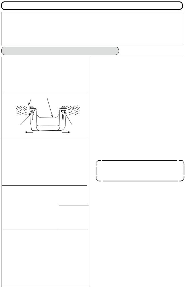
■Installing the under cover
1)The under cover should rest on the four corners of the machine table groove.
2)Fix two rubber seats 1 on side A (operator’s side) using nails 2 as illustrated above. Fix two cushion seats 3 on side B (hinged side) using a rubber-based adhesive. Then place under cover
4 on the fixed seats.
3)Remove air vent cap 5 attached to the machine bed. (Be sure to attach cap 5 when transporting the machine head in the state that the machine head is removed from the machine table.)
If the sewing machine is operated without removing air vent cap 5, oil leakage from gear box portion 7 may occur.
4)Fit hinge 1 into the opening in the machine bed, and fit the machine head to table rubber hinge 8 before placing the machine head on cushions 3 on the four corners.
5)Attach head support rod 6 to the machine table. (However, this step is not necessary for the machine with AK 9 device.)
––
4-2. Removing the needle bar stopper
Remove needle bar stopper 1 for transportation.
Keep the needle bar stopper which has been removed, and install this needle bar stopper when transporting the sewing machine. The needle bar stopper may be cut when it is strongly drawn out. Slightly move the needle bar to the right or left and slowly draw out the
needle bar stopper.
1
4-3. Attaching the knee-lifter
220 mm
2 3
1
Insert knee lifter pad 1 into attaching hole 2 and tighten it with bolt 3.
*Adjust the position of knee lifter pad 1 to a convenient place. For the reference dimension, the position is 220 mm from the bottom face of table.
4-4. Adjusting the height of the knee lifter
1) The standard height of the presser foot lifted using the knee lifter is 10 mm.
2) You can adjust the presser foot lift using knee lifter adjust screw 1.
Do not operate the sewing machine in the state that presser foot 3 is lifted by 10 mm or more since needle bar 2 and presser foot 3, or wiper 4 and presser foot 3 come in contact with each other.
2
4
3
––

4-5. Installing the electrical box
|
|
|
Install the electrical box on the under side of the |
5 |
|
|
|
|
1 |
|
table using round-head bolts 1, plain washers 2, |
|
|
|
|
6 |
|
|
spring washers 3 and nuts 4 supplied with the ma- |
7 |
|
|
chine at the location illustrated, and using bolt having |
|
|
|
hexagonal indentation on the head 5, spring washer |
|
|
|
6 and plain washer 7 supplied with the machine at |
|
|
|
the location illustrated. |
|
|
2 |
|
|
|
3 |
|
|
|
4 |
|
|
|
|
|
4-6. Connecting the power switch cord (Japan and general export area)
|
|
|
|
1) Loosen screw 1 located on the side of the power |
|
|
|
|
|
||
|
|
|
|
|
switch supplied as accessories and remove the |
|
|
|
|
2) |
power switch cover. |
|
|
|
|
Connecting the input power cord of electrical box |
|
|
|
|
|
¡When the input power cord of electrical box is 4P |
|
|
|
|
|
|
Put 4P cord from hole A of the power switch and |
|
|
|
|
|
securely fix green/yellow cord to 5, white cord to 2, |
|
|
|
|
|
black cord to 3 and red cord to 4 with screws. |
|
|
|
|
¡When the input power cord of electrical box is 3P |
|
|
|
|
|
|
Put 3P cord from hole A of the power switch and |
|
|
|
|
|
securely fix green/yellow cord to 5, brown cord to |
|
|
|
|
|
2 and sky blue cord to 3 with screws. |
|
|
|
|
|
|
|
|
|
|
3) |
Connecting the power cable supplied as accessories |
|
|
|
|
||
|
|
|
|
¡In case of 3-phase power cable |
|
|
2 |
|
|
|
Put power cable from hole B of the power switch, and |
|
|
|
|
|
|
A |
|
|
|
|
securely fix green/yellow cord to 9, white cord to 6, |
|
|
|
9 |
|
black cord to 7 and red cord to 8 with screws. |
|
|
|
B |
¡In case of single phase power cable |
|
|
|
|
|
Put power cable from hole B of the power switch, |
|
|
|
|
|
|
and securely fix green/yellow cord to 9 and other |
|
|
|
|
|
cords to 6 and 7 with screws. 8 is not used. |
4 |
3 |
8 |
7 |
4) Installing the power switch cover |
|
|
Securely tighten screw 1 located on the side of |
||||
5 |
|
|
|
|
|
|
|
|
|
|
the power switch. |
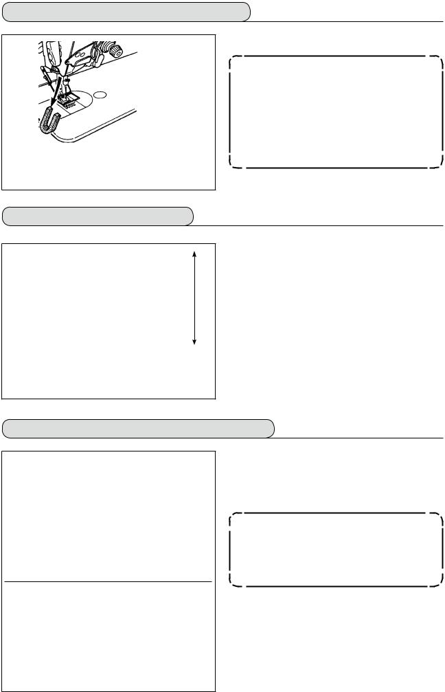
4-7. Installing the operation panel (IT-100D)
1) Install operation panel 1 on the machine head using screws 3 which have been assembled to panel installing bracket 2.
Do not disassemble the operation panel to prevent it from breakage.
––

4-8. Connecting the cords
WARNING :
• To prevent personal injury caused by abrupt start of the sewing machine, carry out the work after turning OFF the power switch and a lapse of 5 minutes or more.
• To prevent damage of device caused by maloperation and wrong specifications, be sure to connect all the corresponding connectors to the specified places.
• To prevent personal injury caused by maloperation, be sure to lock the connector with lock.
• As for the details of handling respective devices, read carefully the Instruction Manuals supplied with the devices before handling the devices.
(1) Preparation of wiring
B
C
E Slowly
a |
b |
|
e |
c |
|
|
|
|
f |
|
d |
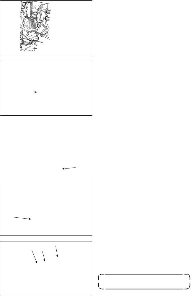
1)Pass the cords coming from the machine head to the underside of the table through hole A in the table.
2)Loosen screws D and lift cord presser plate C of cord passing hole B located on the front cover to the top and temporarily tighten the plate.
3)Remove four screws E fixing the rear cover of the electrical box. When opening the rear cover, pressing it with your hands, slowly open it by approximately 90˚ until it stops as illustrated.
Be sure to lend your hand to the rear cover in order not to let the rear cover fall. In addition, do not apply force to the rear cover opened.
4) Remove the locks of cord clamps a, b, c, d, e, and f.
How to remove the cord clamp
|
1 Lightly pressing |
|
|
2 Pull down the clamp. |
|
|
3 The clamp goes up. |
|
1 |
3 |
2 |
|
||
1
* See P.11 for how to lock the cord clamp.
––
(2)Connecting the connectors
•Each connector has the inserting direction. Check the direction and securely insert it. (In case of the type with lock, insert up to the lock.)
•If the connector is forcibly inserted, trouble or accident will be caused.
•Never pull out the connectors inserted at the time of delivery.
•The sewing machine fails to work if the connectors are not properly inserted. Not only the problem such as the error warning or the like but also breakage of the sewing machine or electrical box will occur.
B
1
b
2
B
34
B
6
5
B
u b
d
c |
i |
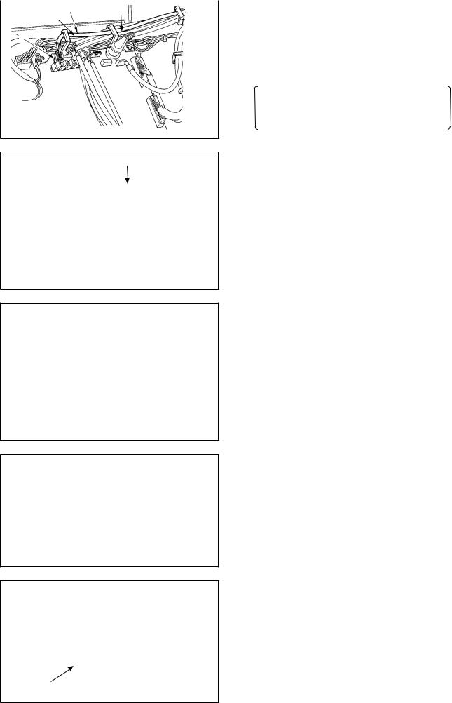
Connect cords in the following order.
5)Insert yellow/green earth cord 1 coming from the machine head inside the electrical box through front cover through hole B, and pass it through cord clamp “b” as illustrated and tighten it with screw at the position 2 in the illustration.
6)Insert white square connector 9P black cord 3 coming from the machine head inside the electrical box through front cover through hole B, and insert it into connector CN38 4 of the circuit board attached to the front cover.
7)Insert white connector 4P black cord 5 coming from the machine head inside the electrical box through front cover through hole B, and insert it into connector CN21 6 of the circuit board attached to the front cover.
8)Insert white connector 26P cord 7 coming from the operation panel inside the electrical box through front cover through hole B, pass it
through cord clamps “b”, “c” and “d”, insert it into connector CN34 8, and lock it.
––
9)Insert black connector 4P white cord 9 coming from the machine head inside the electrical box through front cover through hole B, and insert it into connector CN31 !0.
o
b c
c
!0
10)Insert gray round connector 7P cord !1coming from the machine head inside the electrical box through front cover through hole B, pass it through cord clamp “a”, and insert it into connector CN30 !2.
a 
|
11) |
Insert white connector 12P cord !3coming from |
|
||
|
|
the machine head inside the electrical box through |
b |
|
front cover through hole B, pass it through cord |
|
clamps “b”, “c”, “d” and “g”, and insert it into con- |
|
|
|
|
|
|
nector CN53 !4. |
c |
|
Close cord clamps “b”, “c” and “d”. |
d |
|
|
!3 g |
|
|
!4 |
|
|
|
12) |
Insert white connector 6P three cords !5com- |
|
||
|
||
|
|
ing from the machine head inside the electrical |
|
|
box through front cover through hole B, pass it |
!5 |
|
through cord clamps “a” and “e”, and insert it into |
a |
connector CN54 !6. |
|
e
!6
a
f e
!8
!7
@0
!9
13) Insert white connector 10P cord !7and blue connector 2P cord !8coming from the machine
head inside the electrical box through front cover through hole B, pass them through cord clamps “a”, “e” and “f”, and insert the white 10P into connector CN51 !9and the blue 2P into CN46 @0.
The blue 2P connector is attached only for the machine with thread trimmer.
Close cord clamps “a”, “e” and “f”.
––
f |
@1 e |
a |
|
|
@2
e a
@3
@4
b
c
@6 @5
#0
@7
When the Auto-lifter (AK121) is used :
14)Insert white connector 2P cord @1coming from the machine head inside the electrical box through front cover through hole B, pass it through cord clamps “a”, “e” and “f”, and insert it into connector CN40 @2.
Change the setting of function setting No. 23 from “0” to “1” after completing all set-up procedure. For the details, see p.78 and p.81.
When the bird’s nest prevention device is used (CB type)
15)Insert white small connector 6P cord @3coming from the machine head inside the electrical box through front cover through hole B, pass it through cord clamps “a” and “e”, and insert it into connector CN52 @4.
When foot pedal for standing work (PK70 or 71) is used :
16)Insert black connector 12P cord @5inside the electrical box through front cover through hole B coming from the foot pedal for standing work, pass it through cord clamps “b” and “c”, and insert it into connector CN32 @6.
17)Connect white connector 2P of cord @7supplied as accessories to which red connector 2P and white connector 2P are attached to white connector 2P @8of under cover of the machine head.
Fix omega lock @9supplied as accessories with the neighboring cords and cord @7as shown in the figure.
18)Insert red connector 2P side of cord @7supplied as accessories to which red connector 2P and white connector 2P are attached inside the electrical box through front cover through hole, and insert it into red connector CN25 #0.
– 10 –

How to lock the cord clamp
4
4
3
4 Lightly press the corner of clamp. (Cord clamp is locked with a click.)
Clamp
2
C
|
1 |
A |
B |
|
|
|
|
When the insertion of the connector is completed, lock the cord clamps.
qTake care so that the cord is not caught between the rear cover and the electrical box main body, close the rear cover while pressing section A on the lower side of the rear cover, and tighten four screws 1.
wPress down cord presser plate C of cord through hole B of the front cover, press the cord, and tighten screws 2.
4-9. Attaching the connecting rod
1) Fix connecting rod 1 to installing hole B of pedal lever 2 with nut 3.
2) Installing connecting rod 1 to installing hole A will lengthen the pedal depressing stroke, and the pedal operation at a medium speed will be easier.
4-10. Adjustment of the pedal
■ Installing the connecting rod
1) Move pedal 3 to the right or left as illustrated by the arrows so that motor control lever 1 and connecting rod 2 are straightened.
|
2 |
|
■ Adjusting the pedal angle |
|
|
|
|
||
1 |
|
|
1) |
The pedal tilt can be freely adjusted by changing |
|
|
4 |
2) |
the length of the connecting rod. |
|
|
|
Loosen adjust screw 4, and adjust the length of |
|
|
|
|
|
connecting rod 2. |
3 |
|
|
|
|
– 11 –
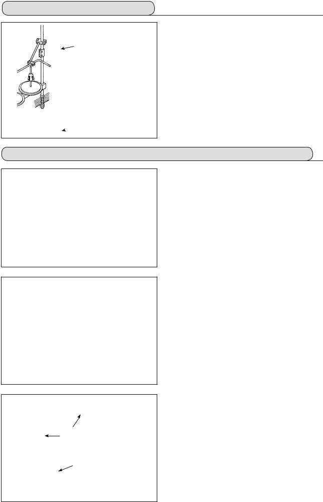
4-11. Installing the thread stand
1) Assemble the thread stand unit, and insert it in the hole in the machine table.
2 2) Tighten locknut 1 to fix the thread stand.
3) For ceiling wiring, pass the power cord through spool rest rod 2.
 1
1
4-12. Installing the bird’s nest prevention (CB) type sewing machine
(bottom surface of the machine table) (mm)
107 106 |
233 |
75
291 34
1)Punch dots on the positions of the setscrews of solenoid valve (asm.) and regulator (asm.) on the bottom surface of the machine table.
Besides, awling is performed on JUKI genuine table.
2)Fix solenoid valve (asm.) 1 with wood screw 2 supplied with the sewing machine as accessories.
3)Fix regulator (total asm.) 3 with wood screw 4 supplied with the sewing machine as accessories.
4)Connect ø6 and ø8 hoses attached to regulator (total asm.) 3 to the respective solenoid valves.
5)Insert dust bag 5 into the top end of hose 9 for dust bag and fix it with band 6 supplied with the sewing machine as accessories.
– 12 –

7
!2
6)Adjust solenoid valve cord (asm.) 7 to the solenoid valve and the hot marker of the cord, and connect it.
Connect 6P connector !0!1to CM52 connector inside the electrical box.(Refer to “When the bird’ s nest prevention device is used, p. 10".)
7)Connect air hose ø4 coming from the machine head to the solenoid valve section and air hose ø8 to the dust bag suction port respectively.
8)Fix the solenoid valve and the air hose on the table with staple 8 supplied as accessories.
1.Fix the staple to such an extent that the air hose is not crushed.
2.Determine the position of the staple so that the cord and the air hose do not hang from the table.
9)Connect the air pipe !2and set the air pressure to 0.6 MPa.
4-13. Lubrication (LZ-2290A-SS • A-SU (-7) )
WARNING :
1. Do not connect the power plug until the lubrication has been completed so as to prevent accidents due to abrupt start of the sewing machine,
2. To prevent the occurrence of an inflammation or rash, immediately wash the related portions if oil adheres to your eyes or other parts of your body.
3. If oil is mistakenly swallowed, diarrhea or vomitting may occur. Put oil in a place where children cannot reach.
1
2
|
|
engraved |
|
Upper |
|
3 |
marker |
line |
|
2
Lower engraved marker line
Fill the oil tank with oil for hook lubrication before operating the sewing machine.
1)Remove oil hole cap 1 and fill the oil tank with
JUKI New Defrix Oil No. 1 using the oiler supplied with the machine.
2)Fill the oil tank with oil up to the place where the top of oil amount indicating rod 3 aligns with the upper engraved line of oil amount indicating window 2. If the oil is filled excessively, it will
leak from the air vent hole in the oil tank or proper lubrication will be not performed. So, be careful.
3)When you operate the sewing machine, refill oil if the top end of oil amount indicating rod 3 comes down to the lower engraved marker line of oil amount indicating window 2.
•When you use a new sewing machine or a sewing machine after an extended period of disuse, run your machine at 3,000 to 3,500 sti/min for the purpose of break-in.
•For the oil for hook lubrication, purchase JUKI New Defrix Oil No. 1 (Part No. : MDFRX1600C0).
– 13 –

4-14. Test run
(1) Turn ON the power
WARNING :
• Check again the power voltage before connecting the power cord.
• Check that the power switch is turned OFF and connect the power cord to the power receptacle.
• Be sure to connect the earth wire.
• In case where the buzzer keeps beeping immediately after turning ON the power, there is a possibility of the wrong connection of cord or wrong power voltage. Turn OFF the power.
1) When the needle bar is in its UP position, zigzag origin detection is performed. 2) When the needle bar is in the position other than UP position :
Display as shown in the figure below appears. Turn the handwheel to bring the needle bar to needle UP position and the display changes to the next screen. Then the needle moves left and right, and zigzag origin detection is performed.
h
(2) How to operate the pedal
A
B
C
D
E
The pedal is operated in four stages.
1)Lightly depress the front part of the pedal for lowspeed operation B.
2)Further depress the front part of the pedal for high-speed operation A. (Note that the sewing machine will enter the high-speed operation mode after the completion of reverse feed stitch-
ing if the automatic reverse feed stitching function is specified with the corresponding switch.)
3)Bring the pedal back to its neutral position, and the sewing machine will stop running C.
(The needle stops in the highest / lowest position.)
4)Strongly depress the back part of the pedal, and the thread trimmer will be actuated E.
Lightly depress the back part of the pedal, and the presser foot will go up D. Further depress the back part of the pedal, and the thread trimmer will be actuated.
– 14 –
5. PREPARATION BEFORE SEWING
5-1. Inserting the needle
WARNING :
To protect against possible personal injury due to abrupt start of the machine, be sure to start the following work after turning the power off and ascertaining that the motor is at rest.
|
|
|
1) |
Turn the handwheel by hand to raise the needle |
|
|
|
||
|
|
|
|
to its highest position. |
|
B |
|
2) |
Loosen the needle clamp screw 2 . Hold the nee- |
|
A |
|
dle 1 so that the long groove B on the needle is |
|
|
|
|
|
facing exactly toward you. |
1 |
|
|
3) |
Insert the needle deep into the hole of the needle |
|
|
|
|
bar in the direction of the arrow until it will go no |
|
2 |
|
|
further. |
|
|
|
4) |
Securely tighten the screw 2 . |
|
|
|
5) |
Confirm that the long groove B on the needle |
|
|
|
|
faces toward you. |
5-2. Removing the bobbin case
WARNING :
To protect against possible personal injury due to abrupt start of the machine, be sure to start the following work after turning the power off and ascertaining that the motor is at rest.
1) Turn the handwheel by hand to raise the needle 1 to its highest position.
2) Raise bobbin case latch 1 and remove the bobbin case.
5-3. Winding the bobbin thread
WARNING :
To protect against possible personal injury due to abrupt start of the machine, be sure to start the following work after turning the power off and ascertaining that the motor is at rest.
|
|
|
1) |
Insert the bobbin deep into the bobbin winder |
|
|
|
||
|
|
1 |
2) |
spindle 5 until it will go no further. |
|
|
|
Pass the bobbin thread pulled out from the spool |
|
|
|
|
|
rested on the right side of the thread stand following |
|
|
|
|
the order from 1 as shown in the figure on the left. |
|
|
|
|
Then, wind the end of the bobbin thread on the bob- |
|
|
|
3) |
bin several times. |
B |
|
|
Press the bobbin winder adjusting plate 6 in the |
|
|
3 |
|
direction of A and start the sewing machine. The bob- |
|
A |
|
|
|
bin rotates in the direction of C and the bobbin thread |
|
|
|
is wound up. The bobbin winder spindle 5 will auto- |
|
C |
|
2 |
|
matically stop as soon as the winding is finished. |
5 |
|
|
4) |
Remove the bobbin and cut the bobbin thread with |
8 |
|
|||
7 |
|
|
5) |
the thread cut retainer 8 . |
|
|
|||
6 |
|
|
To adjust the winding amount of the bobbin thread, loosen |
|
|
|
|
|
setscrew 7 and move bobbin winder adjusting plate 6 |
|
|
|
|
to the direction of A or B. Then, tighten setscrew 7. |
|
|
|
|
To the direction A : The amount is decreased. |
|
|
|
|
To the direction B : The amount is increased. |
|
|
|
|
– 15 –
2
A
2
4
B
2
(Threading)
2
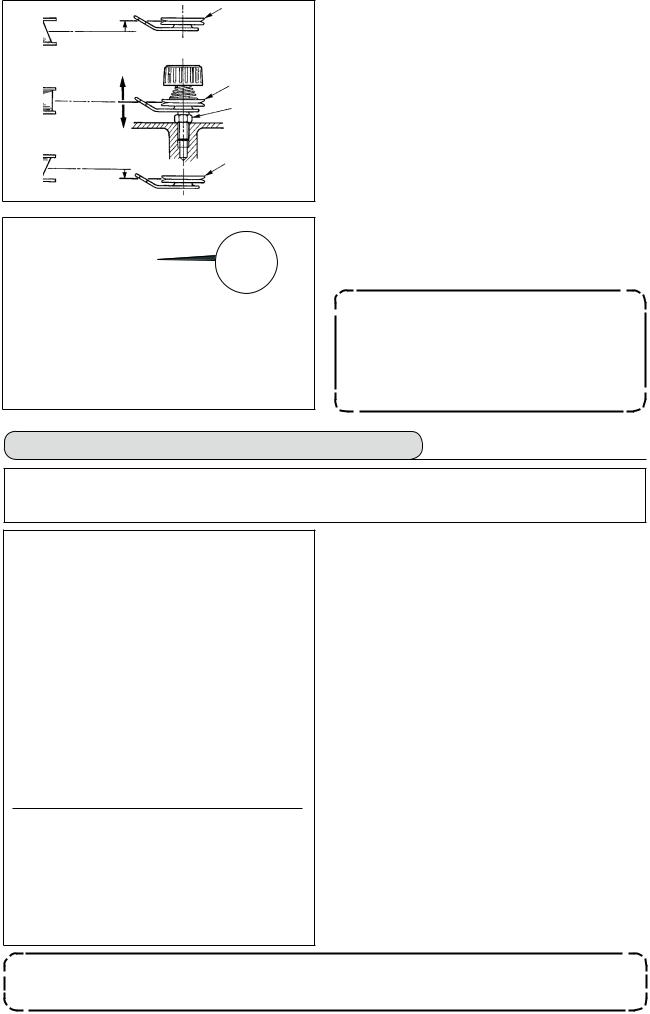
6)In case that the bobbin thread is not wound evenly on the bobbin, loosen the nut 4 and turn the bobbin thread tension to adjust the height of the thread tension disk 2.
•It is the standard that the center of the bobbin is as high as the center of the thread tension disk.
•Move the position of the thread tension disk 2 to the directionAas shown in the figure on the left when the winding amount of the bobbin thread on the lower part of the bobbin is excessive and to the direction B as shown in the figure on the left when the winding amount of the bobbin thread on the upper part of the bobbin is excessive.
After the adjustment, tighten the nut 4 .
7)Turn the thread tension nut 3 to adjust the tension of the bobbin thread winder.
Note 1. When winding bobbin thread, start winding in the state that the thread between bobbin and thread tension disk 2 is tense.
2. When winding bobbin thread in the state that the sewing is not performed, remove needle thread from the thread path of the thread take-up and remove bobbin from the hook.
5-4. Placing the bobbin case and the bobbin
WARNING :
To protect against possible personal injury due to abrupt start of the machine, be sure to start the following work after turning the power off and ascertaining that the motor is at rest.
3
2
B A
1)Turn the handwheel by hand to raise the needle to its highest position.
2)Take a bobbin by your right hand with the thread drawn out about 5 cm from the thread end of the bobbin and place it into the bobbin case as illustrated.
3)Thread the bobbin case in the order of the numbers and pull it out through the thread path as illustrated. The bobbin rotates in the bobbin case in the direction shown by arrow when bobbin thread is drawn.
4)Raise bobbin case latch 1 and hold it between your two fingers as shown in the figure on the left.
5)Insert the bobbin case into the sewing hook shaft as far as it will go by putting your hand from the under cover of the inner hook. (Click sounds.)
6)Release the bobbin case latch to let it steadily rest in the closing position.
■ How to use the bobbin case thread hole
1)Use hole A mainly for zigzag stitches other than 2-step zigzag stitch and scallop zigzag stitch.
2)Use hole B mainly for 2-step zigzag stitch and scallop zigzag stitch.
There may be a case where several stitches at the start of sewing are difficult to be knotted when thread trimmer is used with thin filament thread such as (#50, #60 or #80) using hole B. At this time, use the other hole or perform the sewing starting from the right.
– 16 –
5-5. Threading the machine head
WARNING :
To protect against possible personal injury due to abrupt start of the machine, be sure to start the following work after turning the power off and ascertaining that the motor is at rest.
|
|
|
|
Without auxiliary |
|||
With auxiliary |
|||
thread take-up |
|
thread take-up |
|
|
|
|
1)Turn the handwheel by hand to bring the needle to the most raised position.
2)Pass the thread in the order of the numbers as illustrated.
3)Pull out the thread about 10 cm from the needle after passing it through the needle.
|
|
|
|
LZ-2290A-7 |
LZ-2290A |
||
|
With thread |
|
Without thread |
|
trimmer |
|
trimmer |
Turn the thread once.
5-6. Adjusting the stitch length
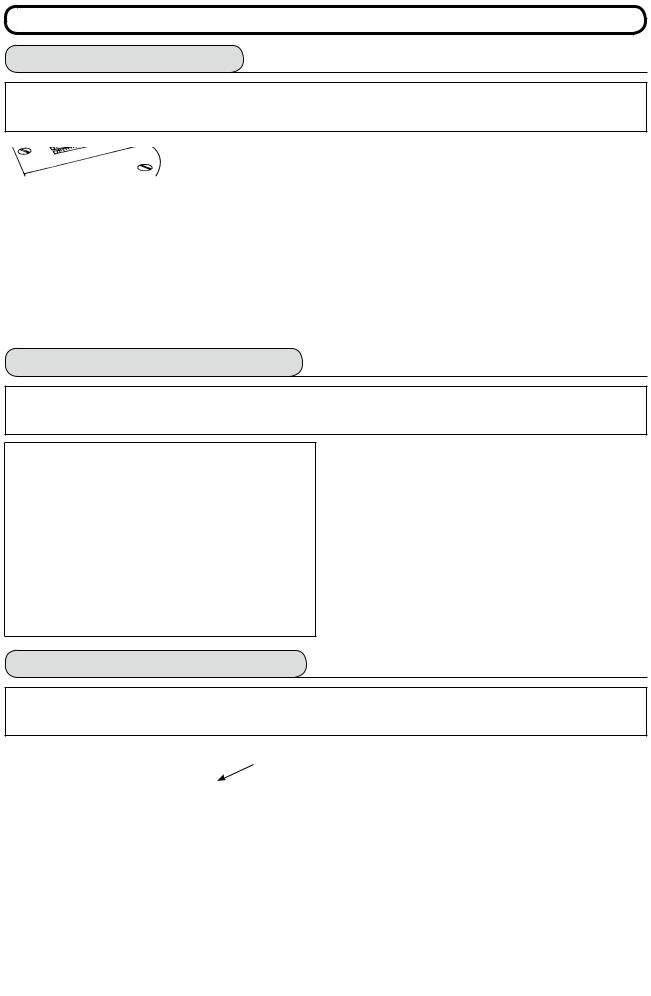
1) Turn the stitch length dial 1 in the direction of the arrow so that the number corresponding to the desired stitch length meets the marker dot A engraved on the machine arm.
2) Numbers on the stitch length dial are calibrated in mm. 3) To perform reverse feed stitching, press down the feed lever 2 . The sewing machine performs reverse feed stitching as long as you keep the feed
lever held pressed. The feed lever will return to its home position and the sewing machine will run in the normal stitching direction when you release the feed lever.
5-7. Adjusting the condensation stitching
Stitch length can be reduced at the start or end of sewing. This feature is used for fastening stitch. 1) Turn condensation stitching adjusting dial 3 in
the direction of the arrow mark, and adjust the desired number to engraved dot B on the machine arm.
2) The number of the graduation is shown in the unit of mm. 3) Turn condensation stitching adjusting dial 3 in the
direction of + to reduce the reverse feed stitch length. Example : When stitch length dial 1 is used with the graduation of +2, the maximum adjustment value
of condensation stitching adjusting dial 3 becomes -2. (It is possible to adjust within the range of -2 to +2.)
Maximum feed amount is regulated to ±2 according to the gauge delivered (feed dog : 22581508). Adjustment can be performed up to the range of maximum +5 to -4 by replacing the  gauge (feed dog : 22540009).
4)Note that the graduations on the dial are mere reference. Adjust the condensation stitching while actually observing the finished seam.
–17 –
6. HOW TO USE THE OPERATION PANEL
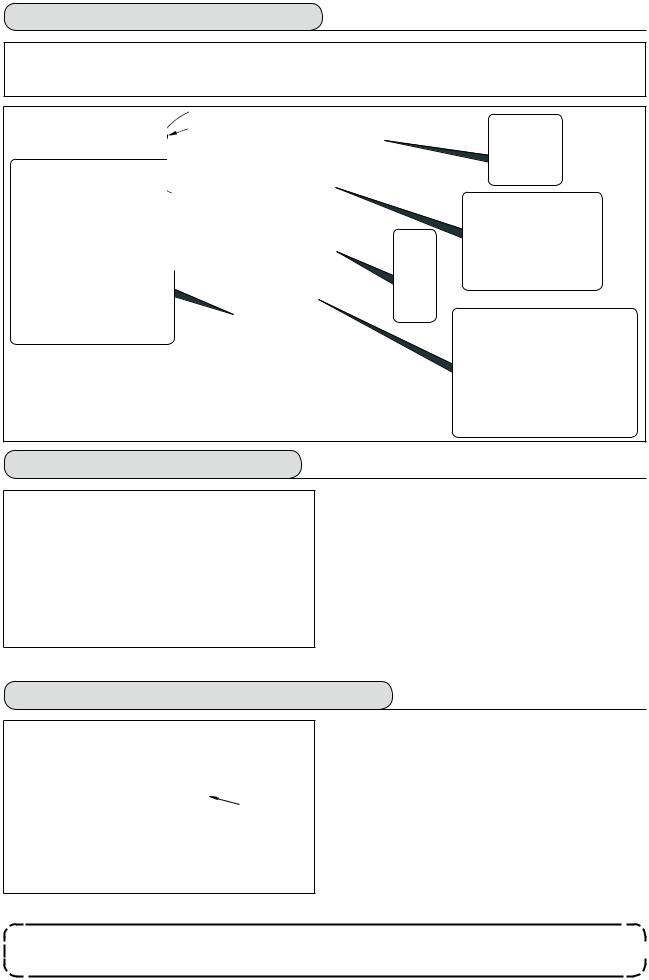
6-1. Names and functions of the respective sections
!7
1 |
4 |
5 |
8 |
7 |
!8 !1!2!4!5 |
2
|
|
|
|
|
|
|
|
|
|
|
|
|
|
|
|
|
|
|
|
|
|
|
|
|
|
|
|
|
|
|
|
|
|
|
|
|
|
|
|
|
|
|
|
|
|
|
|
|
|
|
|
|
|
|
|
|
|
|
|
3 |
|
6 |
|
|
|
|
|
9 |
|
!0 |
!3 |
!6 |
||
|
|
|
|
|
|
|
|
|
|
|
|
|
||
|
|
|
|
|
|
|
|
|
|
|
|
|
||
|
|
|
!7 |
|
|
|
|
|
|
|
|
|||
1 Re-sewing switch |
|
|
|
|
|
|
|
!0Thread trimming prohibiting switch |
||||||
2 Teaching switch |
|
|
|
|
|
|
|
!1Backlight switch |
|
|
||||
3 Needle up/down compensating switch |
!2Reset switch |
|
|
|||||||||||
4 Screen changeover switch |
|
|
|
|
|
|
|
!3Information switch |
|
|
||||
5 With/without reverse feed stitch at sewing start switch |
!4+ switch |
|
|
|
||||||||||
6 With/without reverse feed stitch at sewing end switch |
!5– switch |
|
|
|
||||||||||
7 Material edge sensor switch |
|
|
|
|
|
|
|
!6Counter/speed changeover switch |
||||||
8 One-shot automatic sewing switch |
!7General-purpose switch |
|
||||||||||||
9 With/without automatic thread trimmer switch |
!8Power display lamp |
|
||||||||||||
|
Switch |
Description |
|
Re-sewing switch |
This switch is used to continue sewing from the step on the |
1 |
|
way after replacing bobbin thread when bobbin thread has |
|
|
run out during program stitching step. |
|
Teaching switch |
This is the switch to set the setting of the number of stitches |
2 |
|
with the value of number of stitches which has been actu- |
|
|
ally sewn. |
|
Needle up/down compen- |
This is the switch to perform needle up/down compensating |
3 |
sating switch |
stitching. (Needle up/down compensating stitching and one |
|
|
stitch compensating stitching can be changed over with function |
|
|
setting No. 22.) |
4 |
Screen changeover switch |
This is the switch to change over the screen. |
|
|
|
|
|
|
|
With/without reverse feed |
This is the switch to turn ON/OFF automatic reverse feed |
|
stitch at sewing start switch |
stitch at sewing start. |
5 |
|
* This switch cannot be used with the sewing machine |
|
|
which is not provided with automatic reverse feed stitch- |
|
|
ing device. |
– 18 –

|
Switch |
Description |
|
|
With/without reverse feed |
This is the switch to turn ON/OFF automatic reverse feed |
|
|
stitch at sewing end switch |
stitch at sewing end. |
|
6 |
|
* This switch cannot be used with the sewing machine |
|
|
|
which is not provided with automatic reverse feed stitch- |
|
|
|
ing device. |
|
|
Edge sensor switch |
Selects use/disuse of the material edge sensor in the case |
|
7 |
|
the material edge sensor (edge) is installed on the sewing |
|
|
|
machine. |
|
|
One-shot automatic sewing |
When this switch is pressed, the sewing machine automati- |
|
8 |
switch |
cally operates until the material edge sensor detects the |
|
|
|
material edge or until the set number of stitches is reached. |
|
|
With/without automatic |
This switch is used to automatically trim the thread when |
|
|
thread trimmer switch |
the material edge sensor detects the material edge or until |
|
9 |
|
the set number of stitches is reached. |
|
|
* This switch cannot be used with the sewing machine |
||
|
|
||
|
|
which is not provided with the automatic thread trimming |
|
|
|
device. |
|
|
Thread trimming prohibiting |
This switch prohibits all thread trimmings. |
|
!0 |
switch |
* This switch cannot be used with the sewing machine |
|
|
|
which is not provided with the automatic thread trimming |
|
|
|
device. |
|
!1 |
Backlight switch |
This switch is used to change over the operation of the |
|
|
backlight of the LCD between ON and OFF. |
||
|
|
||
|
|
|
|
|
Reset switch |
This is the switch to make the value of bobbin thread coun- |
|
!2 |
|
ter or sewing counter the set value. This switch is enabled |
|
|
|
after thread trimming. |
|
|
Information switch |
This switch is used to change over the screen between the |
|
|
|
information function screen (sewing common data mode, |
|
!3 |
|
function setting mode, communication mode, version dis- |
|
|
|
play, etc.) and the normal sewing screen. |
|
|
|
This switch is enabled after thread trimming. |
|
|
Plus switch |
This switch is used to increase the set value of the bobbin |
|
!4 |
|
thread counter or the number of pcs. counter at the time of |
|
|
setting. It should be remembered that this switch is enabled |
||
|
|
||
|
|
after thread trimming. |
|
|
Minus switch |
This switch is used to decrease the set value of the bobbin |
|
!5 |
|
thread counter or the number of pcs. counter at the time of |
|
|
setting. It should be remembered that this switch is enabled |
||
|
|
||
|
|
after thread trimming. |
|
|
Counter/speed changeover |
This switch is used to change over the display between the |
|
!6 |
counter display and the maximum sewing speed limitation |
||
switch |
|||
|
|
display. |
|
!7 |
General-purpose switch |
This switch has different functions depending on the |
|
screen. |
|||
|
|
– 19 –
6-2. Before setting the pattern
|
|
|
|
|
|
|
|
|
|
|
|
|
|
|
|
|
|
|
|
|
WARNING : |
|
|
|
|
|
|
|
|
|
|
|
|
|
|
|
|
|
Provide a clearance of 0.5 mm or more between the needle and the gauges when replacing the |
|
|
||||||||||||
|
|
|
gauges such as presser foot, throat plate, etc. |
|
|
|
|
|
|
|
|
|
|
|
|
|
|
|
|
|
If the clearance is smaller than the specified value, it is in danger of |
0.5 |
|
|
|
|
|
|
|
|
|
|
0.5 |
|
|
|
|
|
|
|
|
|
|
|
|
|
|
|
|
||||
|
|
|
causing the needle to be broken or the like. |
|
|
|
|
|
|
|
|
|
|
|
|||
|
|
|
|
|
|
|
|
|
|
|
|
|
|
|
|
||
|
(1) Limitation of the max. zigzag width |
|
|
|
|
|
|
|
|
|
|
|
|
|
|||
|
|
q |
w |
Max. zigzag width limitation value and reference of stitch base line are displayed when |
|||||||||||||
|
|
|
|
the power is turned ON. |
|
|
|
|
|
|
|
|
|
|
|
|
|
|
|
|
|
1 Max. zigzag width limitation value (Screen changes in case of specifying left/right positions.) |
|||||||||||||
|
|
|
|
2 Reference of stitch base line |
|
|
|
|
|
|
|
|
|
|
|
|
|
|
|
|
|
Max. zigzag width limitation value and reference of stitch base line can be performed |
|||||||||||||
|
|
|
|
with ON/OFF. |
|
|
|
|
|
|
|
|
|
|
|
|
|
• Max. zigzag width can be limited in accordance with the gauge.
• There are two kinds of limitations of max. zigzag width.
(1)Zigzag width symmetrical in the center
(2)Specifying left/right positions
■Changeover of limiting procedure of max. zigzag width limitation value
1)Press switch 1.
e w
e
q
2)Press switch 2.
3)Figure on the left side is the zigzag width symmet-
rical in the center mode.
Every time switch 3 is pressed, specifying left/ right positions and zigzag width symmetrical in the center can be changed over alternately.
(1) Zigzag width symmetrical in the center |
(2) Specifying left/right positions |
– 20 –
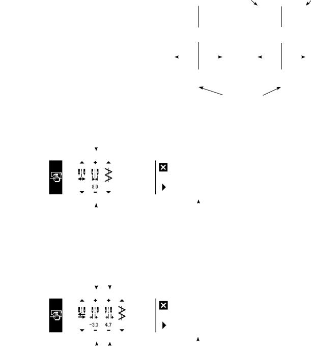
■ How to set max. zigzag width limitation value
Determine whether limitation of zigzag width symmetrical in the center or limitation of left/right positions
in the order of 1) to 3) of the previous page in accordance with the gauge used.
Limitation of zigzag |
|
|
Limitation of |
|
|
|
|
|||||||
width symmetrical |
L = -3.3 |
|
left/right |
|
|
|
R = +4.7 |
|||||||
in the center |
|
|
|
Setting |
|
positions |
|
|
|
Setting |
||||
0.0 |
|
|
|
|
0.0 |
|
|
|
|
|||||
|
|
|
|
|
|
|
|
|||||||
|
Max. |
zigzag |
|
|
|
|
Max. |
zigzag |
|
|
|
|
||
|
width |
limitation |
|
|
width |
limitation |
|
|||||||
|
value |
|
|
|
|
|
value |
|
|
|
|
|
||
|
8.0 |
|
|
|
|
8.0 |
|
|
|
|
||||
|
|
|
|
|
|
|
|
|
|
|
|
|
|
|
–4.0 |
+4.0 |
–3.3 |
+4.7 |
|||||||||||
|
|
|
|
|
Zigzag |
|
|
|
|
|
limitation area |
(A) In case of zigzag width symmetrical in the center |
|
|
|
||
4 |
|
|
|
|
|
|
|
|
|
|
1) Press +/– of switch 4 |
|
|
|
|
|
|
|
|
|
|
|
and set the limitation |
|
|
|
|
|
value. |
|
|
|
|
|
In case of the example, set |
|
|
|
|
|
the value to 8.0. |
|
|
|
|
|
2) Press switch 1 and the |
|
|
|
|
|
screen returns to the |
|
|
|
|
|
|
|
|
|
|
|
|
|
|
|
|
|
previous one. |
4 |
|
1 |
|
||
(B) In case of specifying left/right positions |
|
|
|
||
5 6 |
|
|
|
||
|
|
|
|
|
Change of left side posi- |
|
|
|
|
|
tion limitation |
|
|
|
|
|
1) Press +/– of switch 5 to |
|
|
|
|
|
set the left side limitation |
|
|
|
|
|
value. |
|
|
|
|
|
In case of the example, set |
|
|
|
|
|
the value to -3.3. |
|
|
|
|
|
|
|
|
|
|
|
Change of right side posi- |
5 6 |
1 |
||||
|
|
|
|
|
tion limitation |
2) Press +/– of switch 6 to set the right side limitation value.
In case of the example, set the value to +4.7.
3) Press switch 1 and the screen returns to the previous one.
– 21 –
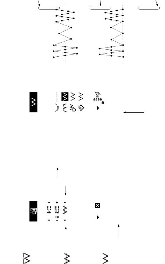
(2) Setting the reference of stitch base line
• Reference position of stitch base line can be set to left, center and right.
Reference of left |
Reference of center |
Reference of right |
stitch base line |
stitch base line |
stitch base line |
■ How to set
2
3
3 1
Reference of left |
Reference of center |
Reference of right |
stitch base line |
stitch base line |
stitch base line |
1) Press switch 1.
1
2) Press switch 2.
3)Figure on the left side
shows the reference of center stitch base line.
Every time switch 3 is pressed, reference of left stitch base line, that of right stitch base line and that of center stitch base line are changed over and set alternately.
4)Press switch 1 and the screen returns to the previous one.
– 22 –
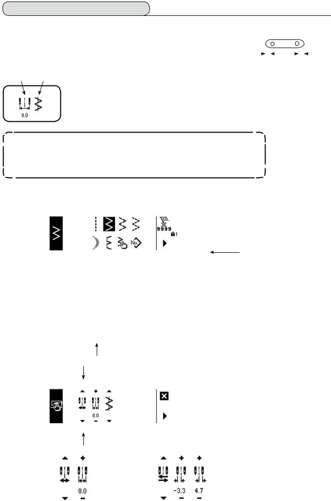
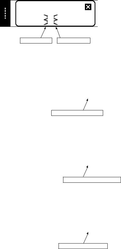
6-3. Basic screen
The screen after turning ON the power source becomes the screen at the time of turning OFF the power source for the last time.
Every time  switch is pressed, the screen changes as follows :
Example) Free stitching of 2-step zigzag with reverse feed stitching (Contents of display change depending on the set values.)
■Sewing shape list first screen
Selection of each shape is performed.
Press s.
Press t.
■ Sewing shape list second screen
Press  .
.
*Free stitching means the general sewing.
■Sewing shape setting screen 
Setting of zigzag width, position of stitch base line, etc. is performed.
Press  .
.
■ Reverse feed stitching setting screen
Setting of kind of condensation, number of stitches, etc. is performed.
Press  .
.
When  is pressed for approximately three seconds in a screen other than the sewing shape list screen, the screen directly transits to the sewing shape list screen.
– 23 –

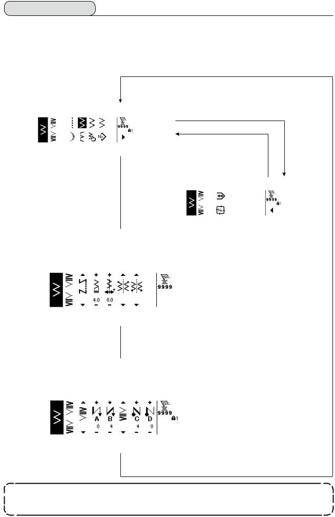
6-4. List of the display pictographs of each screen
■ Sewing shape list first screen
Straight stitch |
2-step zigzag stitch |
3-step zigzag stitch |
4-step zigzag stitch |
Scallop |
Blind stitch |
Custom |
Pattern |
■ Sewing shape list second screen
Continuous stitching
Cycle stitching
■ Scallop selection pop-up screen
Left standard 
 Left crescent
 Left equal 24 stitches
 Left equal 12 stitches
Right standard 
 Right crescent
 Right equal 24 stitches
 Right equal 12 stitches
– 24 –
■ Blind stitch selection pop-up screen
Left blind stitch |
Right blind stitch |
■ Custom pattern selection pop-up screen
Custom pattern new creation
■ Continuous stitching selection pop-up screen
Continuous stitching new creation
■ Cycle stitching selection pop-up screen
Cycle stitching new creation
The key lock level has been set to "1" at the time of delivery, and pictographs of new creation are not displayed. When performing new creation in each mode, change the key lock level to "0". (Refer to the second screen of sewing common data setting of (1) Sewing common data of 6-15. Information. )
In addition, the display of pattern No. at the time of delivery is "1" only.
– 25 –
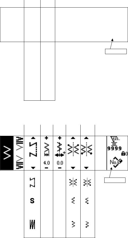
■ Straight stitch sewing shape setting screen
|
|
|
|
Kind of |
Position of |
|
|
sewing |
stitch base line |
|
|
|
|
|
|
|
|
|
|
Pattern register
Free |
|
|
stitching |
– 5.0 |
|
Programmed |
to |
|
|
||
stitching |
5.0 |
|
|
||
Overlapped |
||
|
||
stitching |
|
■ Sewing shape setting screen of 2-step zigzag stitch/3-step zigzag stitch/4-step zigzag stitch
|
|
|
|
|
|
|
Kind of |
Zigzag |
Position of |
Position |
Position |
|
|
sewing |
width |
stitch base |
at sewing |
at sewing |
|
|
line |
start |
end |
|
|
||
|
|
|
|
|||
|
|
|
|
|
|
|
|
|
|
|
|
|
|
Pattern register
Free |
|
|
Optional |
Optional |
|
stitching |
0 |
– 5.0 |
|||
|
|
||||
Programmed |
to |
to |
Right |
Right |
|
|
|
||||
stitching |
10.0 |
5.0 |
|
|
|
|
|
|
|||
Overlapped |
|
|
Left |
Left |
|
stitching |
|
|
|
|
– 26 –
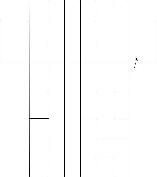
■ Scallop sewing shape setting screen
Kind of |
Zigzag |
Position of |
sewing |
width |
stitch base |
|
|
line |
Position |
Position |
Stop |
|
at sewing |
at sewing |
position |
|
start |
end |
|
|
Root • Crest |
Root • Crest |
|
|
|
|
|
|
|
|
|
|
Pattern register
Free |
|
|
Root |
Optional Optional |
|
stitching |
0 |
– 5.0 |
|||
|
|
||||
Programmed |
to |
to |
|
|
|
|
|
Crest |
Root |
||
stitching |
10.0 |
5.0 |
|||
|
|
|
Overlapped stitching
Right
Left
* Stop position is displayed when the position at sewing end is optional.
– 27 –
Loading...