


PREFACE
This Engineer'sManual is written for the technical personnel who are responsible for the service and maintenance of the machine.
The Instruction Manual for these machines intended for the maintenance personnel and operators at an apparel factory contains operating instructions in detail. And this manual describes "Standard Adjustment", "Adjustment Procedures", "Results of Improper Adjustment", and other important information which are not covered by the Instruction Manual.
It is advisable to use the relevant Instruction Manual and Parts List described below together with this Engineer's Manual when carrying out the maintenance of these machines.
In addition, for the motor for the sewing machine with thread trimmer, refer to the separate Instruction Manual or Engineer'sManual for the motor. And for the control panel, refer to the Instruction Manual for the control panel. This manual gives the "Standard Adjustment" on the former page under which the most basic adjustment value is described, and on the latter page "Results of Improper Adjustment" under which stitching errors and troubles arising from mechanical failures are described together with the CIAdjustment Procedures".
~ |
MO·6900S |
MO-6700S |
MO·6900G |
MO·6900R |
MO·6900J |
|
|||||
N |
|
|
|
|
|
Part No. |
Part No. |
Part No. |
Part No. |
Part No. |
|
|
|
|
|
|
|
Instruction Manual |
29351707 |
29351707 |
29351707 |
29356409 |
29363009 |
|
|
|
|
|
|
Parts List |
29351806 |
29352408 |
29352309 |
29356201 |
29362803 |
ii
ll
11
!
From the Library of Superior Sewing Machine & Supply LLC

CONTENTS
1. SPECIFICATIONS .......... |
•....•..•••.•.••••...•••..••••.••.••••••..•.••... |
••..•........ |
•..•••.•..•••.••.•... |
1 |
||||||
(1) MO-6700S SERIES ........................................................................................................... |
|
|
|
|
|
|
|
|
|
1 |
(2) MO-6900S SERIES ........................................................................................................... |
|
|
|
|
|
|
|
|
|
2 |
(3) MO-6900G SERIES •••••••..•••••••..•••••••... |
••••••..••••..••••.•••••.•.•••.•.... |
•.••... |
•••••... |
•.•••••.•.•.•.•••.•.•.•••.•. |
|
3 |
||||
(4) MO-6900R SERIES •.••.•••••••••••.••••.•••.••••••••.•••••.......•.•..••..•••... |
•....... |
•.•.•••.•.••..•... |
•..••..... |
•.•.•... |
• |
4 |
||||
(5) MO-6900J SERIES............................................................................................................. |
|
|
|
|
|
|
|
|
|
5 |
2. MODEL NUMBERING SYSTEM |
..••.••.•••..••••...••... |
•.•••••••.•••.•..•.••.•... |
•..•... |
••.•... |
•..... |
6 |
||||
3. STANDARD ADJUSTMENT ....••.•.•.•..•••..•.••••.••••••.... |
•...... |
•..•.•••.••...... |
•.•.••.••..... |
•.. |
8 |
|||||
(1) Adjusting the needle height............................................................................................ |
|
|
|
|
|
|
|
|
8 |
|
(2) Positioning the throat plate ............................................................................................ |
|
|
|
|
|
|
|
|
8 |
|
(3) Installing position of the needle Clamp ....................................................................... |
|
|
|
|
|
|
|
10 |
||
(4) Adjusting the length of the lower looper holder |
|
|
|
|
|
|
|
|||
(Applicable only to MO-6.616S / MO-6916R, G, J series) ........................................... |
|
|
|
|
10 |
|||||
(5) Adjusting the lower looper ._.......................................................................................... |
|
|
|
|
|
|
|
|
12 |
|
1) Returning amount of the lower looper .................................................................................................... |
|
|
|
|
|
|
|
|
12 |
|
2) Clearance between the lower looper and the needle ............................................................................. |
|
|
|
|
|
|
|
12 |
||
(6) Position of the upper looper guide ............................................................................... |
|
|
|
|
|
|
|
14 |
||
(7) Positioning the upper looper holder ............................................................................ |
|
|
|
|
|
|
|
16 |
||
(8) Positioning the upper looper ........................................................................................ |
|
|
|
|
|
|
|
|
18 |
|
1) Height of the upper looper ................................................................................................. |
|
|
|
|
|
|
|
~.................... |
|
18 |
2) Longitudinal position of the upper looper ................................................................................................ |
|
|
|
|
|
|
|
18 |
||
(9) Adjusting the double chain looper |
|
|
|
|
|
|
|
|
||
· (Applicable only to M0-6~16S/MO-6916R, G, J |
series) |
............................................... |
|
|
|
|
20 |
|||
1) Returning amount of the double chain looper......................................................................................... |
|
|
|
|
|
|
|
20 |
||
2) Longitudinal motion {Avoid motion) ........................................................................................................ |
|
|
|
|
|
|
|
|
20 |
|
3) Clearance between the double chain looper and the needle ................................................................. |
|
|
|
|
|
|
20 |
|||
(10) Adjusting the height and clearance of the needle guard .............. |
|
~.......................... |
|
|
22 |
|||||
1) For 1-needle or 2-needle overlock machine ........................................................................................... |
|
|
|
|
|
|
|
22 |
||
2) For safely stitch machine ........................................................................................................................ |
|
|
|
|
|
|
|
|
|
22 |
(11) Adjusting the height of the feed dog ......................................................................... |
|
|
|
|
|
|
|
24 |
||
(12) Adjusting the tillt of the feed dog ................................................................................ |
|
|
|
|
|
|
|
24 |
||
(13) Adjusting the differential feed ratio ........................................................................... |
|
|
|
|
|
|
|
26 |
||
(14) Longitudinal position of the feed dog ....................................................................... |
|
|
|
|
|
|
|
26 |
||
(15) Adjusting the presser foot .......................................................................................... |
|
|
|
|
|
|
|
|
28 |
|
1) Adjusting the tilt of the presser foot ........................................................................................................ |
|
|
|
|
|
|
|
|
28 |
|
2) Adjusting the micro-lifting mechanism of the presser foot |
...................................................................... |
|
|
|
|
|
|
28 |
||
(16) Positioning the upper knife arm shaft ....................................................................... |
|
|
|
|
|
|
|
30 |
||
(17) Positioning the upper and lower knives, and available overedge widths .............. |
30 |
|||||||||
1) lower knife ............................................................................................................................................. |
|
|
|
|
|
|
|
|
|
30 |
2) Upper knife ............................................................................................................................................. |
|
|
|
|
|
|
|
|
|
30 |
3) Overdging width ...................................................................................................................................... |
|
|
|
|
|
|
|
|
|
30 |
(18) Resharpening of the knife .......................................................................................... |
|
|
|
|
|
|
|
|
32 |
|
(19) Position of the thread cam (Applicable only to MO-6~16~ series) ........................ |
|
|
32 |
|||||||
1) Adjustment of the thread cam ............................................. |
|
:................................................................... |
|
|
|
|
|
|
32 |
|
2) Adjusting looper thread cam thread guides A and B and the looper thread cam nail ............................. |
|
|
32 |
|||||||
From the Library of Superior Sewing Machine & Supply LLC

rl!~
11
1·
I
I
l~i11
I
,,11
1~
I
I
!I
•l
!I~
I
(20) Adjusting the throat plate support ............................................................................. |
34 |
(21) Adjusting the feed mechanism cover presser .......................................................... |
34 |
(22) Adjusting the looper cover ......................................................................................... |
36 |
(23) Adjusting the cloth chip cover ................................................................................... |
36 |
(24) Adjusting the needle mechanism ............................................................................... |
38 |
(25} Position of the upper looper lubrication pin ............................................................. |
40 |
1) Orientation of the lubricating pin ............................................................................................................. |
40 |
2) Setting the lubricating pin ....................................................................................................................... |
40 |
(26) Longitudinal momentum of the top feed dog (Top feed amount) ........................... |
42 |
(27) Vertical momentum of the top feed dog .................................................................... |
44 |
(28) Adjusting the height of the top feed dog ................................................................... |
46 |
(29) Locus cut of the top feed dog .................................................................................... |
48 |
(30) Adjusting the longitudinal position of the top feed dog .......................................... |
48 |
(31) Adjusting the lateral position of the top feed dog .................................................... |
50 |
(32) Position of the motion of the top feed dog ............................................................... |
52 |
(33) Adjusting the feed bar guides A and B ................................................................. |
~.•.. 54 |
(34) Adjusting the top feed dog pressure ......................................................................... |
56 |
(35) Lifting amount of the top feed dog (when operating the pedal)••....••..••..••....... |
•..••.• 56 |
(36) Height of the presser (pedal operation) ..................................................................... |
58 |
(37} Lifting amount of the top feed dog (when the presser lifting lever is operated) .•• 60
(38) Position of the thread guides and the looper thread take-ups ................................ |
62 |
|
(39) Adjusting soft chain making mechanism .................................................................. |
64 |
|
1) Replacing·the parts with those exclusively designed for making soft chains ......................................... |
64 |
|
2) Adjustment value .................................................................................................................................... |
64 |
- |
3} Important points in adjustment ............................................................................................................... |
65 |
|
(40) Position of the thread guides and the looper thread take-ups of MO-6900G (J) ... |
66 |
|
4. ADDITIONAL INFORMATION AND PRECAUTIONS ..................................... |
68 |
|
(1) Thread tension ............................................................................................................... |
|
68 |
1) Strength of tension spring ....................................................................................................................... |
|
68 |
2) Springs used for each model. ................................................................................................................. |
|
68 |
(2) Upper looper·.................................................................................................................. |
|
69 |
(3) Center-to-center distance of the upper looper holder ............................................... |
69 |
|
(4) Caution in assembly ...................................................................................................... |
|
69 |
1) Application of sealant ............................................................................................................................. |
|
69 |
2) Precautions to be taken with respect to the lubricating components ............................................... |
~...... 71 |
|
(5) Kinds of motor pulleys, belts and frame support plate bolts .................................... |
72 |
|
1) Motor pulleys and belts ........................................................................................................................... |
|
72 |
2) Pat No. of frame support plate bolt ......................................................................................................... |
73 |
|
(6) Inspection and replacement of the cartridge filter ..................................................... |
73 |
|
5. ADJUSTMENT OF THE NEEDLE HEIGHT AND LOOPER TIMMING ........... |
74 |
|
(1) MO-60006. SERIES ........................................................................................................ |
|
74 |
6. TROUBLES AND CORRECTIVE MEASURES ............................................... |
75 |
|
7. DIMENSIONS OF TABLE ••... |
••.••..••••....•.•..•.•.••••.•..•••.•..••••..••.••••••..•••.•••.••..••.•.. |
87 |
(1) Semi-sunken type .......................................................................................................... |
|
87 |
(2) Fully-suken type .................. |
u ........................................................................................ |
88 |
From the Library of Superior Sewing Machine & Supply LLC

1.. SPECIFICATIONS
(1) MO-6700S SERIES
|
|
No. |
Item |
|
|
|
|
|
|
Specifications |
|
|
|
|
||||||||
|
|
1 |
|
Model |
|
M0-67048 |
|
|
|
M0-67148 |
|
. M0-6716$ |
|
|||||||||
|
|
2 |
|
Description |
1-neecile Overlock |
|
2-needle Overlock |
|
2-needle Safety stitch |
|
||||||||||||
|
|
|
|
|
|
machine |
|
|
|
|
|
machine |
|
machine |
|
|||||||
|
|
3 |
|
Stitch type F. S. T. |
JISE13 |
|
JISE24 |
|
JISE13+D12 |
|
||||||||||||
|
|
|
|
|
(USA standard : 504) |
|
(USA standard: 514) |
|
(USA standard =516) |
|
||||||||||||
|
|
|
|
|
|
|
|
|||||||||||||||
|
|
|
|
|
|
|
|
|
|
|
|
|
|
|
|
|
|
|
|
|
|
|
|
|
4 |
|
Sewing speed |
|
|
|
|
|
|
|
7,000,pm |
|
|
|
|
||||||
|
|
5 |
|
Stitch length |
|
. 0.8to4mm |
1.5to4mm |
|
||||||||||||||
|
|
|||||||||||||||||||||
|
|
|
|
|||||||||||||||||||
|
|
6 |
|
Needle gauge |
- |
|
|
|
|
2, 2.4, 3.2 mm |
2. 3.2, 4, 4.8 mm |
|||||||||||
|
|
7 |
|
Overedging width |
1.6, 3.2, 4, 4.8 mm |
|
|
32,4,4.Bmm |
3.2, 4, 4.8, 6.4 mm |
|||||||||||||
|
|
|
|
|
|
|
|
|
|
|
|
|
|
|
|
|
||||||
|
|
8 |
|
Differential feed ratio |
|
Gathering 1 =2 (Max.1 : 4), Stretching 1 : 0.7 (Max.1 : 0.6) |
||||||||||||||||
|
|
|
||||||||||||||||||||
|
|
9 |
|
Needle bar stroke |
|
|
|
|
|
|
|
|
24.5mm |
|
|
|
|
|||||
|
|
10 |
|
Needle tilt angfe |
|
|
|
|
20· |
|
|
|
|
|
|
|
|
|||||
|
|
11 |
|
Needle |
|
ORGAN DC X 27 (Standard) (DC X 1can be used as well.) |
||||||||||||||||
|
|
12 |
|
Presser lifting amount |
|
7.0mm |
|
|
|
|
|
6.5nm |
7.0mm |
|||||||||
|
|
13 |
|
Presser foot pressure |
|
|
|
|
|
|
|
49N (5Kg) |
|
|
|
|
||||||
|
|
|
|
|
|
|
|
|
|
|
|
|
|
|
|
|
|
|
|
|
|
|
|
|
14 |
|
Stitch acfJUstlng method |
|
|
|
|
|
|
By pushbutton |
|
|
|
|
|||||||
|
|
|
|
|
|
|
|
|
||||||||||||||
|
|
15 |
|
Upper knife |
|
|
|
|
|
|
|
|
FlatknHe |
|
|
|
|
|||||
|
|
|
|
|
|
|
|
|
|
|
|
|
|
|
|
|
|
|
|
|
|
|
|
16 |
|
Differential feed adjustment |
|
By lever with micro adjustment medlanism |
|||||||||||||||||
|
|
17 |
|
Weight |
|
|
|
|
|
|
|
|
|
28kg |
|
|
|
|
||||
|
|
18 |
|
Lubrication |
|
|
|
|
Gear-type automatic lubrication |
|
|
|
|
|||||||||
|
|
19 |
|
Lubricating oil |
|
• JUKI MACHINE OIL 18 (Equivalent to ISO VG 18) |
||||||||||||||||
|
|
20 |
|
Needle cooler |
|
|
|
|
|
|
|
|
Optional |
|
|
|
|
|||||
|
|
21 |
Needle thread heat remover |
|
|
|
|
|
|
|
|
Optional |
|
|
|
|
||||||
|
|
22 |
|
Micro presser lifting device |
|
|
|
|
|
Provided as standard |
|
|
|
|
||||||||
|
|
23 |
|
Motor |
|
|
|
|
2P 550W (In case of 7,000 rpm) |
|
|
|
|
|||||||||
|
|
|
|
|
|
2P 400W (in case of less than 7,000 rpm) |
||||||||||||||||
|
|
|
|
|
|
|
|
|
|
|
|
|
|
|
|
|
|
|
|
|
|
|
*JUKI MACHINE OIL 18 (Equivalent to ISO VG 18) Part No. : MML018900CA (900 m g )
-1 -
111
11
11
I'
·I
11
II
11
ij
L'I'
I
r·!I
·1
j
~i
I:
11i.
li
111
Ii
1'
Ii~
i
ii
'I
I i
I
l
.I
I
I
From the Library of Superior Sewing Machine & Supply LLC

(2) MO-6900S SERIES
|
|
|
|
No. |
|
Item |
|
|
|
Specifications |
|
|
|||||||||
|
1 |
|
|
|
|
|
Model |
MD-69045 |
|
M0-6914$ |
|
MQ-69168 |
|||||||||
|
|
|
|
|
|
|
|
|
|
|
|
|
|
|
|
|
|
|
|
|
|
|
2 |
|
|
|
|
|
Description |
1-needle Over1ock |
|
2-neeclle Over1ock |
|
2-needfe Safety stitch |
|||||||||
|
|
|
|
|
|
|
|
|
|
|
|
|
|
machine |
|
machine |
|
|
machine |
||
|
|
|
|
|
|
|
|
|
|
|
|
|
|
|
|
|
|
|
|
|
|
|
3 |
|
|
|
|
|
Stitch type F. S. T. |
JIS E13 |
|
JIS E24 |
|
JISE13+ D12 |
|||||||||
|
|
|
|
|
|
|
|
||||||||||||||
|
|
|
|
|
|
|
|
|
|
|
|
|
|
(USA standard : 504) |
|
(USA standard: 514) |
|
(USA standard : 516) |
|||
|
|
|
4 |
|
|
|
|
|
Sewing speed |
8,500rpm |
|
|
8,000rpm |
||||||||
|
|
5 |
|
|
|
|
|
Stitch length |
|
0.8to4mm |
|
1.5to4mm |
|||||||||
|
|
6 |
|
|
|
|
|
Needle gauge |
- |
|
|
2, 2.4, 3.2 mm |
|
2, 3.2. 4, 4.8 mm |
|||||||
|
|
7 |
|
|
|
|
|
Overedging width |
1.6, 3.2, 4, 4.8 mm |
|
3.2, 4, 4.8 mm |
|
3.2, 4, 4.8, 6.4 mm |
||||||||
|
|
|
|
8 |
|
|
|
|
Differential feed ratio |
Gathering 1 : 2 (Max.1 : 4), Stretching 1 : 0.7 {Max.1 : 0.6) |
|||||||||||
|
|
|
|
|
|
|
|
||||||||||||||
|
|
|
|
9 |
|
|
|
|
|
Needle bar stroke |
|
|
|
24.5mm |
|
|
|||||
|
|
|
|
10 |
|
|
|
|
Needle tilt angle |
|
|
20· |
|
|
|
|
|||||
|
|
|
|
|
|
|
|
|
|
|
|||||||||||
|
|
|
|
.. 11 |
|
|
|
|
Needle |
ORGAN DC X 27 (Standard) (DC X 1 |
can be used as |
weil.) |
|||||||||
|
|
|
|
|
|
|
|
||||||||||||||
|
|
|
|
|
|
|
|
|
|
||||||||||||
|
|
|
|
|
|
|
|
Presser lifting amount |
7.0mm |
|
6.5mm |
|
|
7.0mm |
|||||||
|
|
|
|
12 |
|
|
|
|
|
|
|
||||||||||
|
|
|
|
13 |
|
|
|
|
Presser foot pressure |
|
|
|
49N (5Kg) |
|
|
||||||
|
|
|
|
14 |
|
|
|
Stitch adjusting method |
|
|
|
By pushbutton |
|
|
|||||||
|
|
|
|
15 |
|
|
|
Upper knife |
|
|
|
Flat knife |
|
|
|||||||
|
|
|
|
|
|
|
|
|
|
|
|
|
|
|
|
|
|
|
|
|
|
|
|
|
|
16 |
|
|
|
Differential feed adjustment |
|
By lever with micro adjustment mechanism |
|||||||||||
|
|
|
|
|
|
|
|||||||||||||||
|
|
|
|
17 |
|
|
|
Weight |
|
|
|
28kg |
|
|
|||||||
|
|
|
|
18 |
|
|
|
Lubrication |
|
|
Gear-type automatic lubrication |
|
|
||||||||
|
|
|
|
19 |
|
|
|
Lubricatina oil |
" JUKI MACHINE OIL 18 (Equivalent to ISO VG 18) |
||||||||||||
|
|
|
|
20 |
|
|
|
Needle cooler |
Provided as standard (Exduding some of subclass machines) |
||||||||||||
|
|
|
|
21 |
|
|
|
|
Needle thread heat remover |
Provided as standard {Excluding some of subdass machines) |
|||||||||||
|
|
|
|
22 |
|
|
|
Micro presser lifting device |
|
|
|
Provided as standard |
|
|
|||||||
|
|
|
23 |
|
|
|
Motor |
|
2P 550W (In case of not less than 7,000 rpm) |
||||||||||||
|
|
|
|
||||||||||||||||||
|
|
|
|
|
|
|
|
|
|
|
|
|
|
|
2P 400W (In case of less than 7,000 rpm) |
||||||
|
|
|
|
|
|
|
|
|
|
|
|
|
|
|
|
|
|
|
|
|
|
*JUKI MACHINE OIL 18 (Equivalent to ISO VG 18) Part No. : MML018900CA (900 m ! )
-2-
From the Library of Superior Sewing Machine & Supply LLC

(3) MO-6900G SERIES
|
|
|
No. |
· Item |
|
|
Specifcations |
|
|
|
|
|
|
|
|
|
|
|
||||
|
|
|
|
|
|
|
|
|
|
|
|
|
||||||||||
|
1 |
Model |
M0-6904G |
|
M0-6914G |
|
|
|
|
|
M0-6916G |
|
|
|
|
|||||||
|
2 |
Description |
1-needle Overlock |
|
2-needle Overlock |
|
|
|
|
2-needle Safety stitch |
|
|
|
|
|
|||||||
|
|
|
|
|
machine |
|
machine |
|
|
|
|
|
machine |
|
|
|
|
|||||
|
3 |
Stitch type F. S. T. |
JIS E13 |
|
JISE24 |
|
|
JIS E13+ 012 |
|
|
|
|
||||||||||
|
|
|
|
|
|
|
||||||||||||||||
|
|
|
|
|
(USA standard : 504) |
|
(USA standard : 514) |
|
(USA standard: 516) |
|
|
|
|
|||||||||
|
|
|
|
|
|
|
|
|
|
|
|
|
|
|
|
|
|
|
|
|
|
|
|
4 |
Sewing speed |
|
|
6,000rpm |
|
|
|
|
|
|
|
|
|
|
|
||||||
|
5 |
Stitch length |
2.5to5mm |
|
2.5to4mm |
|
|
|
|
2.5to5mm |
|
|
|
|
||||||||
|
6 |
Needle gauge |
- |
|
2.6mm |
|
|
|
|
4.8mm |
|
|
|
|
||||||||
|
7 |
Overeclging width |
4.8, 10mm |
|
6.4mm |
|
|
|
|
4.8,6.4mm |
|
|
|
|
||||||||
|
|
|
|
|
|
|
|
|
|
|
|
|
|
|
|
|
|
|||||
|
8 |
Differential feed ratio |
Gathering 1: 1.75 (Max.1 : 3.8) |
|
Gathering 1:2(Max.1 : 3.8) |
|
Gathering 1:1.75{Max.1 :3.8) |
|
|
|
|
|||||||||||
|
|
|
|
|
|
|
||||||||||||||||
|
|
|
|
|
Stretchirg 1:0.6 |
|
Stretching 1 :0.7 (Max.1 : 0.6) |
|
Stretching 1:0.6 |
|
|
|
|
|||||||||
|
|
|
|
|
|
|
|
|
|
|
|
|
|
|
|
|
|
|
|
|
||
|
9 |
Needle bar stroke |
|
|
28.8mm |
|
|
|
|
|
|
|
|
|
|
|
||||||
|
|
|
|
|
|
|
|
|
|
|
|
|
||||||||||
|
10 |
Needle tilt angle |
|
20· |
|
|
|
|
|
|
|
|
|
|
|
|
|
|
|
|||
|
|
|
|
|
|
|
|
|
|
|
|
|
|
|
|
|
||||||
|
11 |
Needle |
|
|
ORGAN DO XS |
|
|
|
|
|
|
|
|
|
|
|
||||||
|
12 |
Presser frfting amount |
|
|
Max.Bmm |
|
|
|
|
|
|
|
|
|
|
|
||||||
|
13 |
Presser foot pressure |
|
|
49N(5Kg) |
|
|
|
|
|
|
|
|
|
|
|
||||||
|
14 |
Stitch acfjUSting methcxJ |
|
|
By pushbutton |
|
|
|
|
|
|
|
|
|
|
|
||||||
|
15 |
Upperknife |
|
|
Flat knife |
|
|
|
|
|
|
|
|
|
|
|
||||||
|
16 |
Differential feed adjustment |
By lever with micro adjustment mechanism |
|
|
|
|
|||||||||||||||
|
17 |
Weight |
|
|
28kg |
|
|
|
|
|
|
|
|
|
|
|
||||||
|
18 |
Lubrication |
|
Gear-type automatic lubrication |
|
|
|
|
|
|
|
· |
- |
|||||||||
|
19 |
Llbricating oil |
* JUKI MACHINE OIL 18 (Equivalent to ISO VG 18) |
|||||||||||||||||||
|
||||||||||||||||||||||
|
|
·- |
||||||||||||||||||||
|
|
20 |
Needle cooler |
Provided as standard (Excluding some of subclass machines) |
|
|
|
|
||||||||||||||
|
|
|
|
|
||||||||||||||||||
|
|
|
|
|
|
|||||||||||||||||
|
|
21 |
Needle thread heal remover |
Provided as standard (Excluding some of subclass machines} |
|
|
|
|
||||||||||||||
|
|
|
|
|
|
|||||||||||||||||
|
|
22 |
Micro presser lifting device |
|
|
Provided as standard |
|
|
|
|
|
|
|
|
|
|
|
|||||
|
|
|
23 |
Motor |
|
|
2P400W |
|
|
|
|
|
|
|
|
|
|
|
||||
•JUKI MACHINE OIL 18 (Equivalent to ISO VG 18) Part No. : MML018900CA (900 m 2 )
-3-
From the Library of Superior Sewing Machine & Supply LLC
t
I
l1
I~
~l
11
II
-!
II
I
I

11
I,!11\·
'I
l
fi
11
11
II
·I
i
11
!i
(4) MO-6900R SERIES
|
|
No. |
|
|
|
|
|
|
|
Item |
|
|
|
|
|
Specifications |
|
|
|
||||
|
1 |
|
Model |
|
M0-6904R |
|
|
M0-6914R |
|
|
|
M0-6916R |
|||||||||||
|
2 |
|
Feed type |
|
|
|
|
|
Vertical amount of top feed dog |
|
|
|
|||||||||||
|
3 |
|
Description |
|
1-needle Overlock |
|
2-needle Over1ock |
|
|
2-needle Safety stitch |
|||||||||||||
|
|
|
|
||||||||||||||||||||
|
|
|
|
|
|
|
|
|
|
|
|
r:nachine |
|
|
machine |
|
|
|
machine |
||||
|
|
|
|
|
|
|
|
|
|
|
|||||||||||||
|
|
|
|
|
|
|
|
|
|
|
|
|
|
|
|
|
|
|
|
|
|
|
|
|
4 |
|
|
Stitch type F. S. T. |
|
JIS E13 |
|
JIS E24 |
|
JISE13+D12 |
|||||||||||||
|
|
|
|
|
|
|
|
|
|
|
|
(USA standard : 504) |
|
(USA standard : 514) |
|
{USA standard : 516) |
|||||||
|
5 |
|
|
Sewing speed |
|
|
7,000 rpm (longitudinal amount of top feed less than 6 rrm) |
||||||||||||||||
|
|
|
|
|
|
|
|
|
|
|
|
|
|
6,000 rpm (longitudinal amount of top feed 6 to 8.5 mm) |
|||||||||
|
6 |
|
|
Stitch length |
|
|
|
0.8to4mm |
|
|
|
1.5to4mm |
|||||||||||
|
|
|
|
|
|
|
|
||||||||||||||||
|
|
|
|
|
|
|
|
|
|
|
|
|
|
|
|
|
|
|
|
|
|
|
|
|
7 |
|
|
Needle gauge |
|
- |
|
|
2mm |
|
|
|
32,4.Bmm |
||||||||||
|
|
8 |
|
|
Overedaina width |
|
3.21 4, 4.8, 5.6 mm |
|
|
3.2.4nm |
|
|
3.2, 4, 4.8, 6.4 mm |
||||||||||
|
|
9 |
|
|
Differential feed ratio |
|
|
Gathering 1 : 2 (Max.1 : 4), Stretching 1 : 0.7 (Max.1 : 0.6) |
|||||||||||||||
|
|
|
|
|
|
||||||||||||||||||
|
|
10 |
|
|
Needle bar stroke |
|
|
|
|
|
|
24.5mm |
|
|
|
||||||||
|
|
11 |
|
|
Needle tilt angle |
|
|
|
|
20· |
|
|
|
|
|
|
|||||||
|
|
12 |
|
|
Needle |
|
|
ORGAN DC X 27 (Standard) (DC X 1 can be used as well.) |
|||||||||||||||
|
|
|
|
|
|
||||||||||||||||||
|
|
13 |
|
|
Presser lifting amount |
|
7.0mm |
|
|
6.5mm |
|
|
|
5.5mm |
|||||||||
|
|
14 |
|
|
Presser foot pressure |
|
|
|
|
|
|
49N (5Kg) |
|
|
|
||||||||
|
|
15 |
|
|
Stitch adjusting method |
|
|
|
|
|
By pushbutton |
|
|
|
|||||||||
|
|
|
|
|
|
|
|
|
|
|
|
||||||||||||
|
|
16 |
|
|
Upper knife |
|
|
|
|
|
|
Rat knife |
|
|
|
||||||||
|
|
|
|
|
|
|
|
|
|
|
|||||||||||||
|
|
17 |
|
|
Vertica! amount of top feed dog |
|
|
|
|
|
3.5to8.5mm |
|
|
|
|||||||||
|
|
|
|
|
|
|
|
|
|
|
|
||||||||||||
|
|
18 |
|
Lonaitudnal amountof top feed dog |
|
1 to 7.5 mm (deoending on the ~ifications of the respective machines) |
|||||||||||||||||
|
|
|
|
||||||||||||||||||||
|
|
19 |
|
|
Top feed adjusting type |
|
|
|
|
|
|
By lever |
|
|
|
||||||||
|
|
|
|
|
|
|
|
|
|
|
|
|
|||||||||||
|
|
20 |
|
|
Differential feed adjustment |
|
|
|
By lever with micro adjustment mechanism |
||||||||||||||
|
|
21 |
|
|
Weight |
|
|
|
|
|
|
29kg |
|
|
|
||||||||
|
|
|
|
|
|
|
|
|
|
|
|
|
|
|
|
|
|
|
|
|
|
|
|
|
|
22 |
|
|
Lubrication |
|
|
|
|
Gear-~,pe automatic lubrication |
|
|
|
||||||||||
|
|
|
|
|
|
|
|
|
|
|
|||||||||||||
|
|
23 |
|
|
Lubricating oil |
|
|
|
* JUKJ MACHINE OIL 18 (Equivalent to ISO VG 18) |
||||||||||||||
|
|
24 |
|
|
Needle cooler |
|
|
Provided as standard (Exduding some of subclass machines) |
|||||||||||||||
|
|
25 |
|
|
Needle thread heat remover |
|
|
Provided as standard (Excluding some of subclass machines) |
|||||||||||||||
|
|
26 |
|
|
Micro presser lifting device |
|
|
|
|
|
Provided as standard |
|
|
|
|||||||||
|
|
|
|
|
|
|
|
|
|
|
|
||||||||||||
|
|
27 |
|
|
Motor |
|
|
|
2P 55DW (In case of not less than 7,0CYJ rpm) |
||||||||||||||
|
|
|
|
|
|
|
|
|
|
|
|
|
|
2P 400W (In case of less than 7,000 rpm) |
|||||||||
|
|
|
|
|
|
|
|
|
|
|
|
|
|
|
|
|
|
|
|
|
|
|
|
•JUKI MACHINE OIL 18 (Equivalent to ISO VG 18) Part No. : MML018900CA (900 m f )
-4-
From the Library of Superior Sewing Machine & Supply LLC

(5) MO-6900J SERIES
|
|
No. |
|
|
Item |
|
|
. Specifications |
|
|
|
|
|
|||||||
|
1 |
|
|
Model |
M0-6904J |
|
|
M0-6914J |
|
|
|
M0-6916J |
||||||||
|
2 |
|
|
Feed type |
|
Vertical amount of top feed dog |
|
|
|
|
|
|
|
|||||||
|
3 |
|
|
Description |
1-needle Orerlock |
2-needle Overlock |
|
|
2-needle Safety stitch |
|||||||||||
|
|
|
|
|
|
|
machine |
|
|
machine |
|
|
|
machine |
||||||
|
4 |
|
|
Stitch type F. S. T. |
JIS E13 |
JISE24 |
|
JIS E13+ 012 |
||||||||||||
|
|
|
|
|||||||||||||||||
|
|
|
|
|
|
|
(USA standard: 504) |
(USA standard: 514) |
|
|
(USA standard : 516} |
|||||||||
|
|
|
|
|
|
|
|
|
|
|
|
|
|
|
|
|
|
|||
|
5 |
|
|
Sewing speed |
|
|
|
6,000rpm |
|
|
|
|
|
|||||||
|
6 |
|
|
Stitch length |
2.5to5mm |
2.5to4mm |
|
|
|
2.5to5mm |
||||||||||
|
7 |
|
|
Needle gauge |
- |
|
|
|
2.6mm |
|
|
|
4.8mm |
|||||||
|
8 |
|
|
Overedging width |
4.8mm |
|
|
6.4mm |
|
|
|
4.8,6.4mm |
||||||||
|
|
|
|
|||||||||||||||||
|
9 |
|
|
|
Differential feed ratio |
Gathering 1: 1.75 (Max.1 : 3.8) |
Gathering 1 : 2 (Max.1 : 3.8) |
|
Gathering 1: 1.75 (Max.1: 3.8) |
|||||||||||
|
||||||||||||||||||||
|
|
|
|
|
|
|
Stretching 1 : 0.6 |
Stretching 1: 0.7 (Max.1 : 0.6) |
Stretching 1 : 0.6 |
|||||||||||
|
10 |
|
|
|
Needle bar stroke |
|
|
|
|
28.8mm |
|
|
|
|
|
|||||
|
11 |
|
|
|
Needle tilt angle |
|
|
20· |
|
|
|
|
|
|
|
|
|
|||
|
12 |
|
|
|
Needle |
|
|
ORGAN DOX5 |
|
|
|
|
|
|||||||
|
13 |
|
|
|
Presser lifting amount |
|
|
|
Max.8mm |
|
|
|
|
|
||||||
|
|
|
|
|
|
|
|
|
|
|
||||||||||
|
14 |
|
|
|
Presser foot pressure |
|
|
|
49N (5Kg) |
|
|
|
|
|
||||||
|
15 |
|
|
|
Stitch acfJUsting method |
|
|
By pushbutton |
|
|
|
|
|
|||||||
|
|
|
|
|
|
|
|
|
|
|
|
|
|
|
|
|
|
|
|
|
|
16 |
|
|
|
Upper knife |
|
|
Square knife |
|
|
|
|
|
|||||||
|
17 |
|
|
|
Vertical amount of top feed doa |
|
|
3.5to8.5mm |
|
|
|
|
|
|||||||
|
18 |
|
|
|
Longitudinal amount of top feed dog |
2.7 to 7.0 mm (depending on the specifications of the respective machines) |
||||||||||||||
|
19 |
|
|
|
Top feed adjusting type |
|
|
|
|
By lever |
|
|
|
|
|
|||||
|
|
|
|
|
|
|
|
|
|
|
|
|
||||||||
|
|
20 |
|
|
|
Differential feed adjustment |
|
By lever with micro adjustment mechanism |
||||||||||||
|
|
|
|
|
||||||||||||||||
|
|
21 |
|
|
|
Weight |
|
|
|
|
29kg |
|
|
|
|
|
||||
|
|
22 |
|
|
|
Lubrication |
|
Gear-type automatic lubrication |
|
|
|
|
|
|||||||
|
|
23 |
|
|
|
Lubricating oil |
*JUKI MACHINE OIL 18 (Equivalent to |
ISO VG |
18} |
|
||||||||||
|
|
24 |
|
|
|
Needle cooler |
Provided as standard (Exduding some of subclass machines) |
|||||||||||||
|
|
|
|
|||||||||||||||||
|
|
25 |
|
|
|
Needle thread heat remover |
Provided as standard (Excluding some of subclass machines) |
|||||||||||||
|
|
26 |
|
|
|
Micro presser lifting device |
|
|
Provided as standard |
|
|
|
|
|
||||||
|
|
|
|
|
|
|
|
|
|
|
|
|
|
|
|
|
|
|
|
|
|
|
27 |
|
|
|
Motor |
|
|
|
|
2P400W |
|
|
|
|
|
||||
|
|
|
|
|
|
|
|
|
|
|
|
|
|
|||||||
|
|
|
|
|
|
|
|
|
|
|
|
|
|
|
|
|
|
|
|
|
*JUKI MACHINE OIL 18 (Equivalent to ISO VG 18) Part No. : MML018900CA (900 m £ )
I
I
I!l,
I,
11
I
i
ii
11
11
.I
l
-5-
From the Library of Superior Sewing Machine & Supply LLC

!j~'.
i
I
I
I
~I
1
11
II
I
ll
I
~
I
11
·I
11
ri! i
I
11:
11
I
2. MODEL NUMBERING SYSTEM
MO-6000 SERIES MODEL NUMBERING SYSTEM
1 |
2 |
3 |
4 |
5 |
6 |
7 |
8 |
9 |
10 |
11 |
12 |
13 14 15 |
16 |
17 |
18 |
19 20 |
21 |
22 |
M06666DDD6666/D666-DO6
4 Machine code
7 ·6700 series
9 6900 series
7 Basic specification code
|
s |
Standard |
||
* |
G |
|
Extra heavy-weight materials |
|
* |
A |
Variable top feed type |
||
,I |
J |
|
Variable top feed type for |
|
|
|
|
extra heavy-weight materials |
|
|
|
|
|
|
|
* 6900only |
|||
5. 6 Seam code
03 |
Splicing |
|
|
|
|
04 |
1-needle 3-threa~ overtock (504) |
|
|
|
|
05 |
For blind hemmong (505) |
|
|
|
|
12 |
2-neeclle 4-thread mock safety stitch (512) |
|
|
|
|
14 |
2-needle 4-thread overtock (514) |
|
|
|
|
16 |
2-needle S.thread safety stitch (516) |
|
|
|
|
43 |
3-needle 6-thread safety stitch |
|
|
|
|
45 |
2-needle double chainstitch |
|
|
|
8 Needle gauge code
0 1-needle
B2.0mm
C2.4mm,
26 mm (for extra- heavy-weight materials)
D |
|
32mm |
|
||
|
|
|
E |
|
4.0mm |
|
|
|
F |
|
4.8mm |
|
|
|
1 |
|
4.8 mm+ 2.0 mm |
9 Overedging width code |
|
|
1O Feed dog code |
|
|
|
11 Material code |
|
||||||||
|
|
|
|
|
|
|
|
|
|
|
|
|
|
|
|
|
|
A |
1.6mm |
|
|
4 |
2-row |
|
|
|
Classification based on materials to be used |
||||||
|
D |
3.2mm |
|
|
|
5 |
1-row |
|
|
1 |
Extra light-weight to light- |
For light-weight materials such as |
||||
|
|
|
||||||||||||||
|
E |
4.0mm |
|
|
|
6 |
3-row |
|
|
|
|
weight materials |
shirts or the Uke |
|||
|
|
|
|
|
|
|
|
|||||||||
|
F |
4.8mm |
|
|
|
7 |
4-row |
|
|
2 |
Light-weight to medium- |
Knit wear only |
||||
|
|
|
|
|||||||||||||
|
|
|
|
|
|
|
|
|
|
-----3 |
|
|
||||
|
H |
6.4mm |
|
|
|
|
|
|
weight materials |
General fabrics |
||||||
|
|
|
|
|
|
|
|
|||||||||
|
M |
10.0mm |
|
|
|
|
|
|
4 |
Medium-weight to heavy- |
Knit wear only such as sweater or |
|||||
|
|
|
|
|
|
|
|
|
|
|
-5 |
weight materials |
the fike |
|||
|
N |
18.0mm |
|
|
|
|
|
|
|
|||||||
|
|
|
|
|
|
|
|
Medium·weightto heavy-weight |
||||||||
|
|
|
|
|
|
|
|
|
|
|
|
|
|
|||
|
|
|
|
|
|
|
|
|
|
|
|
|
|
------ |
|
materials such as denim or the like |
|
|
|
|
|
|
|
|
|
|
|
|
|
|
|
||
|
|
|
|
|
|
|
|
|
|
|
|
|
|
|
For heavy-weight materials |
|
|
|
|
|
|
|
|
|
|
|
|
|
|
6 |
|
||
|
|
|
|
|
|
|
|
|
|
|
|
|||||
|
|
|
|
|
|
|
|
|
|
|
|
|
7 |
Heavy-weight to extra |
Heavy-weight materials for jeans, car |
|
|
|
|
|
|
|
|
|
|
|
|
|
|||||
|
|
|
|
|
|
|
|
|
|
|
|
|
|
|
heavy-weight materials |
mattress, etc. |
|
|
|
|
|
|
|
|
|
|
|
|
|
|
|
||
|
|
|
|
|
|
|
|
|
|
|
|
|
|
|
|
|
12 Application code
Classification based on type of operation
and process
0 Standard
1For blind stitching
2Forgathering
4For attaching tape
5For binding
6For binding tape
DSplicing•
ECar mattress
FSoft chain
•In case of the splicing, 13th figure is (1).
- 6 -
From the Library of Superior Sewing Machine & Supply LLC
13 Special machine code
Special classification of machine, structure and specification other than gauge set
0 Standard
6Feed dog provided w~h a lip
7Upper looper high throw type
F For swim suits
H Upper looper extra high throw type
M For zipper
1 For splicing
15 to 18 Device and attachment code
G0'2/O141 |
Presser fo(?Vtape guide for attaching tape |
|
G39/Q141 |
Presser foot (for sharp curve)/tape guide for |
|
|
attaching tape |
|
|
|
|
L121 |
Blind hemming ruler |
|
|
|
|
S159 |
Swing type ruffler (pedal-intertocking type for safety |
|
|
stitch} |
|
|
|
|
S161 |
Swing type ruffler (Manual lever type for safety |
|
|
stitch) |
|
|
||
|
|
|
S162 |
Swing type ruffler (Manual lever type for over1ock) |
|
|
|
|
N077 |
Four-fold binder |
20 Machine head code
AStandard machine head (Common to all specifications)
21 Accessory code
A |
Fa general export * |
|
|
B |
ForJE |
|
|
G |
For China |
22 Machine head code
0Fully-sunken type
Semi-sunken type
The numberings after-..!'(hyphen) of 19th figure will be used on
and after Apnl 1, 2002. They are not described on the catalogue or the fike.
• The general export s~ification is for Hong Kong, U.SA, Japan and Singapore.
.. 7 -
I
J
l
j
I
I
11
lj
I,
\
I
i
I
II
·1
~
j:
11
I
11
11
I
,j
,,
ij!11
11
I
ll
I~
!
I
I
I
From the Library of Superior Sewing Machine & Supply LLC
i'
!
1·
I
I
j
I:
II'
I
I
I·
1;
ii
I
.I
I! i
I
I
I
I
3. STANDARD ADJUSTMENT
Standard Adjustment
(1) Adjusting the needle height
When the needle(s) is in the highest position,
the needle height from the throat plate surface should be as shown below.
|
|
|
|
|
|
|
|
|
|
|
|
|
|
|
|
|
|
|
|
|
|
|
(Unit: mm) |
|
|
|||
|
6~046 |
|
|
- |
|
|
|
|
|
|
|
|
|
Model |
|
|
1-needle/ |
2-needle : right |
|
|
||||||||
|
·· |
|
|
|
|
|
|
|
|
|
|
|
|
|
|
|||||||||||||
|
|
|
|
|
|
|
|
|
|
|
|
|
|
|
|
|
|
|
|
2-needle : left |
|
|
|
|
|
|
||
|
|
|
|
|
30 - |
|
|
MO6l!.04S(R) -l!.66 |
·l!..60 |
10.5 |
|
|
- |
|
|
|
|
|||||||||||
|
11 z,z 1 ,inJ,a |
|
|
|
|
|
|
|
|
|
|
|
|
-Lib.6 |
|
|
|
|
|
|
|
|
|
|
||||
|
|
|
|
|
|
|
|
|
|
|
|
|
|
|
|
|
|
|
|
|
|
|
||||||
|
|
|
|
SD |
~ |
:I |
|
|
MO6604S |
|
-D.D.D. |
·66H |
11.3 |
|
|
- |
|
|
|
|
||||||||
|
|
|
|
Cl) |
:II," |
Cl) |
|
|
|
|
|
|
|
|
|
|||||||||||||
|
~ |
|
|
|
n |
::i., |
CD |
|
|
|
|
|
|
|
|
|
SOM |
|
|
|
|
|
|
|
|
|
|
|
|
|
|
|
|
|
|
|
|
|
|
|
|
|
|
|
|
|
|
|
|
|
|
||||||
|
|
|
|
|
g: R |
~ |
|
|
|
|
|
|
|
|
|
|
|
|
|
|
|
|
|
|
|
|
||
|
|
|
|
|
|
|
|
|
|
|
|
|
|
|
|
|
|
|
|
|
|
|
|
|
||||
|
|
|
|
|
|
|
|
|
|
|
|
|
|
|
|
|
|
|
|
|
|
|
|
|
|
|
|
|
|
66146 |
|
|
|
|
|
|
|
|
|
MO- 6/\05S |
-606 |
|
-66.H |
11.3 |
|
|
- |
|
|
|
|
||||||
|
|
|
|
|
|
|
fl) |
|
|
|
|
|
|
|
|
|
507 |
11 :0 |
|
|
9.4 |
|
|
|
|
|||
|
|
|
|
|
|
|
|
|
|
|
|
|
|
|
|
|
|
|
|
|
|
|
|
|
|
|
||
|
|
|
|
|
|
|
::, |
|
|
|
MO- 6.6.125 |
|
-D.D.D. |
SOF |
|
|
|
|
|
|
|
|
|
|
||||
|
|
|
|
|
|
|
|
|
|
|
|
|
|
|
|
|
|
|
|
|
||||||||
|
|
|
|
|
|
3 Cl) |
|
|
|
|
|
|
|
|
|
|
|
|
|
|
|
|
|
|
|
|
||
|
|
|
|
|
|
|
Cl) |
|
|
|
|
|
|
|
|
|
|
|
|
|
|
|
|
|
|
|
|
|
|
|
|
|
|
|
|
e: |
|
|
|
|
|
|
|
|
|
|
|
|
|
|
|
|
|
|
|
||
|
.,[!~zzma |
|
|
|
|
I» |
|
|
MOSD.12S |
|
-CE4 |
-40H |
11.3 |
|
|
9.9 |
|
|
|
|
||||||||
|
|
|
|
|
|
|
|
|
|
|
|
|
|
|||||||||||||||
|
|
|
|
|
n |
a, |
|
|
|
|
|
|
|
|
|
|
|
|
|
|
|
|
|
|
|
|
||
|
|
|
|
|
|
0 |
|
|
|
MO· 6614S (R) -B66 - |
0H |
|
|
|
|
|
|
|
|
|
|
|||||||
|
|
|
|
|
|
2:o |
|
|
MOSb14S (R) -8~6 |
-3c7 |
10.5 |
|
|
9.1 |
|
|
|
|
||||||||||
|
|
|
|
|
|
:, |
< |
|
|
|
|
|
|
|
|
|||||||||||||
|
|
|
|
|
|
CD |
Cl> |
|
|
|
|
|
|
|
|
|
2 |
|
11.3 |
|
|
9.9 |
|
|
|
|
||
|
|
|
|
|
|
|
0 |
|
|
|
|
|
|
|
|
|
|
|
|
|
|
|
|
|
||||
|
|
|
|
|
|
|
::i. |
|
|
|
|
|
|
|
|
|
40H |
|
|
|
|
|
|
|
|
|
|
|
|
|
|
|
|
|
|
':,t: |
|
|
|
|
|
|
|
|
|
|
|
|
|
|
|
|
|
|
|
||
|
66166 |
|
|
|
|
|
|
|
|
|
|
|
|
|
|
|
|
|
|
|
|
|
|
|
|
|
||
|
|
|
|
|
|
|
|
|
|
MO- 6b16S(R)-D.D.b |
-.t.60 |
|
10.5 |
|
|
- |
|
|
|
|
||||||||
|
n |
|
|
|
|
en |
|
|
MO- Sil16S(R)-b.66 |
-l!..6H |
|
11.3 |
|
|
|
- |
|
|
|
|
||||||||
|
|
|
|
3 e. |
|
|
|
|
|
|
|
|
|
|
||||||||||||||
|
|
|
|
II> |
a, |
|
|
MO- 6Li16S(R)-A.6.L'l |
-60H |
|
13 |
|
|
- |
|
|
|
|
||||||||||
|
|
|
|
g.~ |
|
|
|
|
|
|
|
|
|
|||||||||||||||
|
|
|
|
-· en |
|
|
MO6943R |
|
-6.D.6 |
-b.l::,7 |
|
10.5 |
|
|
9.9 |
|
|
|
|
|||||||||
|
|
|
|
i~ |
|
|
|
|
|
|
|
|
|
|
|
|
|
|
|
|
|
|
|
|
||||
|
|
|
|
|
|
MO66.43S |
|
-61::J.{:j, |
·6.D.H |
|
11.3 |
|
|
9.9 . - |
|
|
||||||||||||
|
|
|
|
|
|
|
|
|
|
|
|
|||||||||||||||||
|
|
|
|
|
::r |
|
|
|
|
|
|
|
|
|||||||||||||||
|
|
|
|
|
|
|
|
|
|
|
|
|
|
|
|
|
|
|||||||||||
|
C2'Z2222Z]n |
|
|
|
|
|
|
|
MO- 6/\45S |
|
-D.b.l:l |
-360 |
|
9.8 |
|
|
- |
|
|
|
|
|||||||
|
|
|
|
|
|
|
|
|
|
|
|
|
|
|
|
|
|
|
||||||||||
|
|
|
|
|
|
:i5: |
|
|
|
MO· 6903G |
|
-ON6 |
-3D1 |
|
15.4 |
|
|
- |
|
|
|
|
||||||
|
|
|
|
|
|
|
|
|
|
|
|
|
|
|
|
|
||||||||||||
|
|
|
|
|
|
0 |
|
|
|
MO· 6904GCJl-OF6 |
-700 |
|
14.4 |
|
|
- |
|
|
|
|
||||||||
|
|
|
|
|
|
0, |
|
|
|
|
|
|
|
|
|
|
||||||||||||
|
|
|
|
|
|
|
|
|
|
|
|
|
|
|
|
|
|
|
|
|
|
|
|
|
||||
|
|
|
|
|
|
CD |
|
|
|
MO6905G |
|
·OM6 |
-760 |
|
15.4 |
|
|
- |
|
|
|
|
||||||
|
|
|
|
|
|
0 |
|
|
|
|
|
|
|
|
|
|
|
|
||||||||||
|
|
|
|
|
|
|
|
|
|
|
|
|
|
|
|
|
|
|||||||||||
|
|
|
|
|
|
p |
|
|
|
MO- 6914G(Jl-CH6 |
-700 |
|
14.1 |
|
|
12.6 |
|
|
|
|
||||||||
|
|
|
|
|
|
|
|
|
|
|
|
|
|
|
|
|||||||||||||
|
|
|
|
|
|
<- |
|
|
|
|
|
|
|
|
|
|
|
|
|
|
|
|
|
|
|
|
|
|
|
|
|
|
|
|
|
|
|
MO- 6916G(J)-F.0.6 |
-700 |
|
14.1 |
|
|
- |
|
|
|
|
|||||||||
|
|
|
|
|
|
|
|
|
|
|
|
|
|
|
|
|
|
|||||||||||
The adjustment of needle height for the 2-needle overlock machine should be made in reference to the left needle.
(2) Positioning the throat plate
The needle entry point should be such that the distances listed below are provided between the needle slot edge of the throat plate and the center of needle.
Over1ock side A |
1.3 |
|
|
|
(Unit: mm) |
Double·chainstitchside B |
1.0 |
|
|
|
|
Note that "A:=1.8" and "8=1.5"' |
A |
|
for M0-6~16S (R) -n6.6-60H, |
||
|
||
"A=1.6" and "8=1.3" for M0-69~6G, J |
|
-8-
From the Library of Superior Sewing Machine & Supply LLC

Adjustment Procedures |
Results of Improper Adiustment |
|
|
|
|
1) Take off the upper cover, loosen setscrew 8. of needle driving |
o Any other needle height than |
|
forked crank O and move needle driving forked crank O up or |
specified here will badly affect |
|
down to adjust the needle height. |
the action of the lower looper. |
|
|
the timing for.catching the upper |
|
|
looper thread, etc. |
|
(Caution) Do not fully loosen the setscrew 8 of the needle |
o |
Improper lateral position of the |
||
driving forked crank 0. |
|
needle driving forked crank will |
||
If the needle driving forked crank has got out of position |
|
cause seizure, play, or other |
||
laterally when its setscrew was loosened, fully loosen the |
|
troubles. |
|
|
setscrew and turn pulley to allow the forked crank to tum |
|
|
|
|
until it settles by itself. Then tighten the setscrew to fix the |
|
|
|
|
forked crank at that position. |
|
|
|
|
|
|
|
||
1} Loosen setscrews 8 of throat plate base O and move throat |
o |
Improperly positioned throat |
||
plate base 8 back and forth to adjust dimension A or B. |
|
plate will |
cause |
needle |
|
|
breakage, |
contact |
of the |
|
|
needles will the throat plate, or |
||
other troubles.
-9-
From the Library of Superior Sewing Machine & Supply LLC
,11
!I
:-1
;ii
II
I
1l
Ii
I
'I
!1
'I
11
'!i~
I
Standard Adjustment
(3) Installing position of the needle clamp
Needle clamp connecting stud O should fit with the bottom end of needle bar 8 or spaced within oto
0.5mm.
Oto 0.5 mm
Butt the needle clamp with the |
0 |
bottom end of the needle bar. |
|
(4) Adjusting the length of the lower looper holder (Applicable only to M0-6~16S / M0-6916R, G, J series)
The center-to-center distance should be 26 mm.
At this time, the clearance between the end surface of the arm and the neck of the ball should be
3.5mm.
26mm
-10 -
From the Library of Superior Sewing Machine & Supply LLC

|
Adjustment Procedures |
Results of Improper Adjustment |
|
|
|
|
|
|
1) Loosen setscrew O and adjust, by slightly turning needle clamp |
o If the clearance provided |
|
|
8. the clearance provided between the right-hand side needle |
betw~en the needle and the |
|
|
and the lower looper (for 2-needle overlock machine) and the |
looper is excessive, the needle |
|
|
|
||
|
|
||
|
clearance provided between the needle hole in the throat plate |
thread will be likely to skip at the |
|
|
and the needle (for safety stitch machine). |
time of tucking. |
|
|
|
o If the clearance provided |
|
|
|
between the needle and the |
|
|
|
looper is insufficient, the needle |
|
|
|
will break or the looper blade |
|
|
|
point will be damaged causing |
|
|
|
|
|
|
|
thread breakage. |
|
|
|
|
|
|
|
|
|
|
|
|
|
|
|
|
|
1)Loosen setscrew O of the lower looper holder from the rear of the frame.
Since it is difficult to accurately measure the center-to-center distance. perform adjustment to provide a 3.5 mm distance between the end surface of the arm and the neck of the ball as illustrated.
oIncreasing the center-to-center distance will give a smaller stroke of the duble chain looper or lower looper, and decreasing the distance will give larger stroke.
II ll
·I'
I
I
I
I
·1
I
-11 -
From the Library of Superior Sewing Machine & Supply LLC

Standard Adjustment
(5) Adjusting the lower looper
1) Returning amount of the lower looper
The distance between the blade point of the lower looper and the center of the needle should be as follows when the lower looper is at the extreme left of its stroke.
|
|
|
|
|
|
|
|
|
|
|
|
|
|
|
|
|
|
|
|
|
|
|
|
|
|
|
|
|
|
|
|
(Unit: mm) |
||||||
|
|
|
|
|
|
|
|
|
|
|
Model |
|
|
|
|
|
|
|
|
|
|
|
|
|
|
|
|
|
|
Dimension8 |
||||||||
|
|
|
|
|
|
|
|
|
|
|
|
|
|
|
|
|
|
|
|
|
|
|
|
|
|
|
|
|
|
|
|
|
|
|
|
|
|
|
|
|
|
|
|
|
|
|
|
6604S{R) |
|
OAS |
|
|
156 |
|
|
|
|
|
|
|
|
|
|
- |
|||||||||||||
|
|
|
|
|
|
|
|
|
|
|
|
|
|
|
|
|
|
|
|
|
|
|||||||||||||||||
|
|
|
|
|
|
|
|
|
|
|
|
|
|
|
|
|
|
|
|
|
|
|
|
|
|
|
|
|
|
|
4.0 |
|
|
|
||||
|
.:.:: |
|
|
|
|
MO- SD.OSS |
|
·OA4to OE4 |
|
|
·210 |
|
|
|
|
|
|
|
|
|
|
|
|
|||||||||||||||
|
|
|
|
|
|
|
|
|
|
|
|
|
|
|
|
|
|
|
|
|||||||||||||||||||
|
8 |
|
|
|
|
|
|
|
|
|
|
|
006 |
|
|
|
|
|
3t).~ |
|
|
|
|
|
|
|
||||||||||||
|
~ (D |
|
|
|
|
|
|
|
|
OF4 |
|
|
|
|
3t).O |
|
|
|
|
|
|
|
||||||||||||||||
|
> |
C: |
MO· 6604S{R)- |
|
|
|
|
|
|
|
|
|
|
|
|
|
|
|
|
|
|
|
|
|
|
|
|
|
|
|||||||||
|
o:c |
|
OF6 |
|
|
|
|
|
|
|
|
|
|
|
|
|
|
|
|
|
|
|
3.7 |
|
|
|
||||||||||||
|
Cl> |
u |
|
|
|
|
|
|
|
|
|
|
500 |
|
|
|
|
|
|
|
|
|
|
|
|
|
|
|||||||||||
|
- |
"' |
|
|
|
|
|
|
|
|
|
|
OH4 |
|
|
|
|
SOM |
|
|
|
|
|
|
|
|||||||||||||
|
ie |
|
|
|
|
|
|
|
|
|
|
|
|
|
|
|
|
|
|
|
|
|
||||||||||||||||
|
Cl> |
|
|
|
|
|
|
|
|
|
|
|
|
|
|
|
|
|
|
|
|
|
|
|
|
|
|
|
|
|
|
|
|
|
|
|
|
|
|
c;= |
|
|
|
|
|
|
|
|
|
|
|
|
0D4 toOE4 |
|
|
. |
46H |
|
|
|
|
|
|
|
|||||||||||||
|
|
|
|
|
|
MO- 6604S • |
|
OF6 |
|
|
|
|
|
|
|
|
|
|
|
|
|
|
|
|
|
3.8 |
|
|
|
|||||||||
|
|
|
|
|
|
|
|
|
|
|
|
|
|
|
|
|
|
|
|
50H |
|
|
|
|
|
|
|
|||||||||||
|
8 |
|
|
|
|
|
|
|
|
|
|
|
|
B04 to BE4 |
|
|
-3lH |
|
|
|
3.8 |
|
|
|
||||||||||||||
|
|
|
|
|
MO- 6'°'14 S(R) • B06 to BES |
|
|
|
|
|
|
|
|
|||||||||||||||||||||||||
|
.:.:: |
|
|
|
|
|
|
|
|
|
|
|
|
|
|
|
|
|
|
|
|
|
|
|
|
|
|
|
|
|
|
|
|
|
|
|
|
|
|
ii |
|
|
|
|
|
|
|
|
|
|
|
|
|
|
|
|
|
|
|
|
|
|
|
|
|
|
|
|
|
|
|
|
|
|
|
|
|
|
(D |
|
|
|
|
|
|
|
|
|
|
|
|
|
|
|
|
|
|
|
|
|
|
|
|
|
|
|
|
|
|
|
|
|
||||
|
> |
C |
MO- 6614S(R) - 806 to BFS |
|
|
|
|
20H |
|
|
|
|
|
|
|
|||||||||||||||||||||||
|
o·- |
|
|
|
|
|
|
|
|
|
|
|
|
|
|
|
|
|
|
|
|
|
|
|
||||||||||||||
|
..92 |
'g |
|
|
|
|
|
|
|
|
BE7 |
|
|
|
|
4uH |
|
|
|
|
3.8 |
|
|
|
||||||||||||||
|
je |
MO66125 |
|
-CE4 |
|
|
·40H |
|
|
|
4.0 |
|
|
|
||||||||||||||||||||||||
|
C |
|
|
|
|
|
|
|
|
|
|
|
|
|
|
|
|
|
|
|
|
|
|
|
|
|
|
|
|
|
|
|
|
|
|
|
|
|
|
(\I |
|
|
|
|
MO- 6612S |
|
·DF6 |
|
|
|
|
50F |
|
|
|
|
|
|
|
||||||||||||||||||
|
|
|
|
|
|
|
|
|
507 |
|
|
|
|
|
|
|
|
|
|
|
2.2 |
|
|
|
||||||||||||||
|
|
|
|
|
|
|
|
|
|
|
|
|
|
|
|
|
|
|
|
|
|
|
|
|
|
|
|
|
|
|
|
|||||||
|
|
|
|
|
|
MO· 6616S(A) -66.0. |
|
|
360 |
|
|
|
|
|
|
|
|
|
|
|
|
|
|
|||||||||||||||
|
|
|
|
|
|
|
|
500 |
|
|
|
|
|
|
|
|
|
|
|
3.7 |
|
|
|
|||||||||||||||
|
~ |
|
|
|
|
|
|
|
|
|
|
|
|
|
|
|
|
|
|
|
|
|
|
|
|
|
|
|
|
|
|
|||||||
|
|
|
|
|
|
|
|
|
|
|
|
|
|
|
|
|
|
|
|
|
|
|
|
|
|
|
|
|
|
|
|
|||||||
|
~ <D |
|
|
|
|
|
|
|
|
|
BE4 |
|
|
|
|
|
|
|
|
|
|
|
|
|
|
|
|
|
|
|
|
|
|
|
||||
|
. : |
C |
|
|
|
|
|
|
|
|
. |
|
|
46.H |
|
|
|
|
|
|
|
|||||||||||||||||
|
~~ |
|
|
MO- 6.t).16S(R) |
-00/.\ |
|
|
|
|
|
|
3.8 |
|
|
|
|||||||||||||||||||||||
|
-e |
|
|
|
|
|
|
|
|
F66 |
|
|
|
|
56H |
|
|
|
|
|
|
|
||||||||||||||||
|
QI |
"' |
|
|
|
|
|
|
|
|
|
|
|
|
|
|
|
|
|
|
|
|
|
|
|
|
|
|
|
|
|
|
|
|
|
|
||
|
t8 |
|
|
|
|
|
|
|
|
|
|
|
|
|
|
|
|
|
|
|
|
|
|
|
|
|
|
|
|
|
|
|
|
|
|
|
|
|
|
|
|
|
|
|
MO· |
|
6616S(R) |
|
|
·F66 |
|
|
|
|
-60H |
|
|
|
2.8 |
|
|
|
|||||||||||||||
|
|
|
|
|
|
MO6943R |
-666 |
|
|
|
-6.67 |
|
|
|
|
|
|
|
|
|
3.8 |
|
|
|
||||||||||||||
|
|
|
|
|
|
MO6643S |
-6.6.6 |
|
|
|
|
|
-.ti.6.H |
|
|
|
3.8 |
|
|
|
||||||||||||||||||
|
|
,. |
|
|
MO6903G |
|
-ON6 |
|
|
|
-301 |
|
|
|
|
|
|
|
|
|
|
1.4 |
|
|
|
|||||||||||||
|
|
|
|
MO6904G(J) |
·OF6 |
|
|
-700 |
|
|
|
|
|
|
|
|
|
|
3.5 |
|
|
|
||||||||||||||||
|
• |
C, |
|
|
|
|
|
|
|
|
|
|
|
|
|
|
|
|||||||||||||||||||||
|
Og |
|
|
|
|
|
|
|
|
|
|
|
|
|
|
|
|
|
|
|
|
|
|
|
|
|
|
|
|
|
|
|
|
|
||||
|
MO6905G |
|
-OM6 |
|
|
-760 |
|
|
|
|
|
|
|
|
|
1.3 |
|
|
|
|||||||||||||||||||
|
:E a, |
|
|
|
|
|
|
|
|
|
|
|
|
|
|
|
|
|
|
|
|
|
|
|
|
|
|
|
|
.. |
|
|
|
|
||||
|
|
MO- 6914G(J) |
-CHS |
|
|
-700 |
|
|
|
|
|
|
|
|
3.3 |
|
|
|
||||||||||||||||||||
|
|
U) |
|
|
|
|
|
|
|
|
|
|
|
|
|
|
|
|||||||||||||||||||||
|
|
|
|
|
|
|
|
|
|
|
|
|
|
|
|
|
|
|
|
|
|
|
|
|
|
|
|
|
|
|
|
|
|
|
|
|
|
|
|
|
|
|
|
|
MO6916G(J) |
|
-F66 |
|
|
-700 |
|
|
|
|
|
|
|
|
|
|
3.5 |
|
|
|
|||||||||||||
|
|
|
|
|
|
|
|
|
|
|
|
|
|
|
|
|
|
|
|
|
|
|
|
|
|
|
|
|
|
|
|
|
|
|
|
|
|
|
2) Clearance between the lower looper and the needle
The clearance should be Oto 0. 1 mm.
0to0.1 mm
J
- 12 -
From the Library of Superior Sewing Machine & Supply LLC
Adjustment Procedures |
Results of Improper Adjustment |
|
|
|
|
1) Returning amount of the lower looper |
o |
Excessive return of the lower |
CD Loosen setscrew • of lower looper support arm 8 and adjust |
|
looper tends to cause·stitch |
lower looper 8 to make adjustment of the returning amount. |
|
skipping when filament thread is |
(Referential information) |
|
used. |
|
|
|
1. Radius 8 of lower looper 8 will be 66.9 mm when the lower |
o |
Insufficient return of the lower |
looper is inserted into lower looper support arm O until it |
|
looper tends to cause needle |
contacts with stopper pin O and then is fixed. |
|
thread stitch skipping when |
2. The rocking angle of the lower looper will be 2s·. |
|
spun thread is used. |
(M0-66665, R)
The rocking angle of the lower looper will be 32·.
(M0-6966G, J)
2) Clearance between the lower looper and the needle |
o |
Excessive clearance will often |
MO-6700S Series |
|
cause needle thread stitch |
CD Loosen setscrew 8 of lower looper support arm O to the extent |
|
|
|
skipping. |
|
that it is temporarily tightened. Now, make the adjustment by |
o |
Insufficient clearance will cause |
moving lower looper support arm 8 back and forth. |
|
needle breakage due to the |
MO-6900S, R, G, J Series. |
|
contact of the looper with the |
CD Loosen setscrew 8 of lower looper support arm 8 to the extent |
|
needle, or produce scratches on |
that it is temporarily tightened. Then finely adjust the longitudinal |
|
the blade point of the looper. |
position of the looper using fine adjustment screw O. |
|
leading to needle thread |
® Turn fine adjustment screw 8 clockwise to move lower looper |
|
breakage or other troubles. |
G away from the needle. |
|
|
Tum the screw counterclockwise to move lower looper 8 closer |
|
|
to it. |
|
|
-13-
From the Library of Superior Sewing Machine & Supply LLC

Standard Adjustment
(6) Position of the upper looper g~ide
Vertical position :
To be in close contact with the frame guide surface. Laternal position :
To be pressed against the upper looper guide support gauge 8.
0
Frame guide surface
(Unit: mm)
|
|
|
|
|
|
|
|
|
(Unit: mm) |
|
|
|
|
&St |
|
5.8~7 |
|||||
Upper |
|
|
|
|
|
|
|
|
||
looper |
|
|
|
|
|
|
|
|
||
13131909 |
|
|
13132006 |
|||||||
guide |
|
|
||||||||
|
|
|
|
|
|
|
|
|||
support |
11 |
|
|
|
|
|
||||
gauge |
|
|
~ |
|||||||
|
|
|
|
|
|
|
|
|||
|
|
|
11545100 |
|
|
12375606 |
||||
|
|
|
|
|
|
|
|
|
|
|
(Unit: mm)
|
|
|
|
|
|
|
|
|
|
|
|
|
|
|
|
|
|
|
|
|
|
|
|
|
|
|
|
|
|
|
|
|
|
|
|
|
|
|
|
|
|
|
|
|
|
|
|
|
|
|
Model |
|
|
|
|
Dimension Ci) |
|
|
|
|
|
|
|
|
Modef |
|
|
|
|
Dimension(B |
|||||||||||||||||||||||
Q) |
|
|
|
|
OAS |
15A |
|
|
a-i |
|
|
|
|
|
|
|
|
|
|
|
|
|
|
|
|
|
|
|
|
|
|
|
|
|
|
|
|
|
||||||||
c:: |
|
|
|
|
|
|
|
|
|
|
|
|
|
|
|
|
|
|
|
|
|
|
|
|
|
360 |
|
|
3 |
|
|
|
||||||||||||||
£ |
|
MO·S.604S(R) -OA4 lo OE4 |
-210 |
|
|
|
|
|
|
MO- 6.6.16S{R) |
|
-6.Ab. |
|
|
|
|
|
|||||||||||||||||||||||||||||
|
|
|
|
|
|
|
|
500 |
|
|
|
E@ |
||||||||||||||||||||||||||||||||||
co |
|
6.605S |
|
|
|
|
|
|
|
|
|
|
|
|
|
|
|
|
|
|
|
|
|
|
|
|
|
|
|
|
|
|
|
|
||||||||||||
E |
|
006 |
|
|
|
|
3.6A |
|
|
|
|
a, |
|
|
|
|
|
|
|
|
|
|
|
|
|
|
|
|
|
|
|
|
|
|||||||||||||
~ |
|
|
|
|
|
|
|
|
|
|
|
|
|
|
|
|
|
|
|
C |
|
|
|
|
|
|
|
|
|
|
|
|
|
|
|
|
|
|
|
|
|
|
|
|
|
|
|
|
|
|
|
|
|
|
|
|
|
|
|
|
|
|
|
|
|
:E |
|
|
|
|
|
|
|
|
|
|
|
|
|
|
|
|
|
|
|
|
|
|
|
|
|
|
|
8 |
|
|
|
|
|
OF4 |
360 |
|
|
|
|
|
|
0 |
|
|
|
|
|
|
|
|
BE4 |
|
46H |
|
~y |
|
||||||||||||||||||
'C |
MO- 66.04S(A)-OF6 |
-500 |
|
~-3 |
|
|
|
co |
MO· 6/\16S(R) |
-00.6. |
|
|
|
|
|
|||||||||||||||||||||||||||||||
~ |
|
|
|
|
|
|
|
|
E |
|
|
|
- |
|
|
|
||||||||||||||||||||||||||||||
|
|
|
|
|
OH4 |
|
|
SOM |
|
|
|
|
|
|
..c:; |
|
|
|
|
|
|
|
|
F.6..6. |
|
SOH |
|
|||||||||||||||||||
a, |
|
|
|
|
004 to0E4 |
4AH |
@~ |
|
|
|
g |
|
|
|
|
|
|
|
|
|
|
|
|
|
|
|
|
|
|
|
|
|
|
|
|
|
|
|||||||||
'g |
|
|
|
|
|
|
~ |
MO· 6A16S{R) |
|
-F.6.6 |
-60H |
|
r,s.s |
|||||||||||||||||||||||||||||||||
M0-6.l!:.045 |
·OF6 |
|
|
|
|
|
|
|||||||||||||||||||||||||||||||||||||||
a, |
|
|
|
|
?:- |
|
|
|
|
|
|
|
|
|
|
|
|
|
|
|
|
|
|
|
|
|
[iliJ |
|||||||||||||||||||
~ |
|
|
|
|
|
|
|
|
|
|
|
50H |
|
|
|
|
|
|
.S! |
|
|
|
|
|
|
|
|
|
|
|
|
|
|
|
|
|
|
|
|
|
||||||
|
|
|
|
|
|
|
|
|
|
|
|
|
|
|
|
|
|
|
|
co |
|
|
|
|
|
|
|
|
|
|
|
|
|
|
|
|
|
|
|
|
|
|
|
|
|
|
|
|
|
|
|
|
BD4toBE4 |
|
|
|
|
[f] |
|
|
|
|
|
|
|
|
|
|
|
|
|
|
|
|
|
|
|
|
|
|
|
|
|
|
|
||||||||
|
|
|
|
|
|
-3.6.7 |
|
|
|
|
|
Cl) |
MO. 6943R |
|
-61.).A |
-D.D.7 |
|
|
|
|
|
|
||||||||||||||||||||||||
0 |
|
MO·6614S(R)·sosto BEG |
|
|
|
|
|
|
|
|
|
|
|
|
|
|
|
|
|
|
|
|
|
|
|
|
|
|
~ |
|
|
|
||||||||||||||
a, |
|
|
|
|
|
|
|
|
|
|
|
|
|
|
|
|
|
|
|
|
|
|
|
|
|
|
|
|
|
|
|
|
||||||||||||||
C |
|
|
|
|
|
|
|
|
|
|
|
|
|
|
|
|
|
|
|
|
|
|
|
|
|
|
|
|
|
|
|
|
|
|
|
|
|
|
|
|
|
|
|
|
|
|
:c |
|
|
|
|
|
|
|
|
|
|
|
|
!...;6 |
|
|
|
|
|
|
|
|
|
|
|
|
|
|
|
|
|
|
|
|
|
|
|
|
|
|
|
|
|
|
|||
t'G |
|
|
|
|
|
|
|
|
|
|
|
|
,~ |
|
|
|
|
|
|
|
|
|
|
|
|
|
|
|
|
|
|
|
|
|
|
|
|
|
|
|
|
|
|
|||
|
|
|
|
|
|
|
|
|
|
|
|
|
|
|
|
|
|
|
|
|
|
|
|
|
|
|
|
|
|
|
|
|
|
|
|
|
|
|
|
|
|
|||||
MQ. |
|
S(R}-806 to BF6 |
0 |
|
|
|
|
|
MO· 6.6.43S |
.,6_1.),,6, |
|
|
-6D.H |
|
i |
|||||||||||||||||||||||||||||||
E |
|
|
|
|
|
|
|
|
|
|||||||||||||||||||||||||||||||||||||
|
|
|
6614 |
|
|
|
|
|
|
|
|
20H |
|
|
|
|
|
|
|
|
|
|
|
|
|
|
|
|
|
|
||||||||||||||||
~ |
|
|
|
|
BE7 |
4.llH |
|
|
|
|
|
|
|
|
|
|
|
|
|
|
|
|
|
|
|
|
|
|
|
|
|
|||||||||||||||
'C |
|
|
|
|
|
|
|
|
|
|
|
|
|
|
|
|
|
|
|
|
|
|
|
|
|
|
|
|
|
|
|
|
|
|
|
|
|
|
|
|
||||||
8 |
|
|
|
|
|
|
|
|
|
|
|
|
|
|
|
|
|
|
|
|
|
|
|
|
|
|
|
|
|
|
|
|
|
|
|
|
|
|
|
|
|
|
|
|
|
|
a, |
|
|
|
|
|
|
|
|
|
|
|
|
|
|
|
|
|
|
|
|
|
|
|
|
|
|
|
|
|
|
|
|
|
|
|
|
|
|
|
|
|
|
|
|
|
|
MO- |
6612S |
-CE4 |
-40H |
|
|
|
|
|
|
|
|
|
|
|
|
|
|
|
|
|
|
|
|
|
|
|
|
|
|
|
|
|
|
|
|
|
||||||||||
> |
|
~7 |
|
|
|
|
MO. 6903G |
|
-ON6 |
-301 |
|
|
|
[iJ |
||||||||||||||||||||||||||||||||
=o |
|
|
|
|
|
|
|
|
|
|
|
|
|
|
|
|
|
|
|
|
|
|
|
|
|
|
|
|
|
|
|
|
|
|
|
|
|
|||||||||
0 |
|
|
|
|
|
|
|
|
|
|
|
|
|
|
|
|
|
|
|
|
|
|
|
|
|
|
|
|
|
|
|
|
|
|
|
|
|
|
|
|
|
|
|
|
|
|
Q) |
|
|
|
|
|
|
|
|
|
|
|
|
|
|
|
|
|
|
|
|
|
|
|
|
|
|
|
|
|
|
|
|
|
|
|
|
|
|
|
|
|
|
|
|
|
|
a, |
|
|
|
|
|
|
|
|
|
|
|
|
|
|
|
|
|
|
|
|
|
|
|
|
|
|
|
|
|
|
|
|
|
|
|
|
|
|
|
|
|
|
|
|
|
|
|
|
|
|
|
|
|
|
|
|
|
|
|
|
ffil |
|
|
|
|
|
|
|
|
|
|
|
|
|
|
|
|
|
|
|
|
|
|
|
|
|
|
|
|
|
|||
Q) |
|
|
|
|
|
|
|
|
|
|
0 507 |
|
|
|
|
|
|
MO- 6904G(J) -OF6 |
|
-700 |
|
|
|
|
|
|
|
|
||||||||||||||||||
C |
|
|
|
|
|
|
|
|
|
|
|
|
|
|
|
|
|
|
~~~ |
|
|
|
|
|||||||||||||||||||||||
"' |
|
MO· 6.6.12S |
·DF6 |
SOF |
|
|
|
|
|
|
|
|
|
|
|
|
|
|
|
|
|
|
|
|
|
|
|
|
|
|
|
|
|
|||||||||||||
|
|
|
|
|
|
|
|
|
|
|
|
|
|
|
|
|
|
|
|
|
|
|
|
|
|
|
|
|
|
|
|
|
|
|
|
|
||||||||||
|
|
|
|
|
|
|
|
|
|
|
|
|
|
|
|
|
|
|
""') |
|
|
|
|
|
|
|
|
|
|
|
|
|
|
|
|
|
|
|
|
|
|
|
|
|
|
|
|
|
|
|
|
|
|
|
|
|
|
|
|
|
|
|
|
|
|
|
cj |
|
|
|
|
|
|
|
|
|
|
|
|
|
|
|
|
|
|
|
|
|
|
|
|
|
|
|
|
|
|
|
|
|
|
|
|
|
|
|
|
|
|
|
|
|
|
MO• 6905G |
|
-OM6 |
-1.6.0 |
|
|
|
ff: |
|||||||||||||||||||
|
|
|
|
|
|
|
|
|
|
|
|
|
|
|
|
|
|
|
0 |
|
|
|
|
|||||||||||||||||||||||
|
|
|
|
|
|
|
|
|
|
|
|
|
|
|
|
|
|
|
6 |
|
|
|
|
|
|
|
|
|
|
|
|
|
|
|
|
|
|
|
|
|
||||||
|
|
|
|
|
|
|
|
|
|
|
|
|
|
|
|
|
|
|
0 |
|
|
|
|
|
|
|
|
|
|
|
|
|
|
|
|
|
|
|
|
|
|
|
|
|
|
|
|
|
|
|
|
|
|
|
|
|
|
|
|
|
|
|
|
|
|
|
CJ) |
|
|
|
|
|
|
|
|
|
|
|
|
|
|
|
|
|
|
|
|
|
|
|
|
|
|
|
|
|
|
|
|
|
|
|
|
|
|
|
|
|
|
|
|
|
|
CD |
|
|
|
|
|
|
|
|
|
|
|
|
|
|
|
|
|
|
|
|
|
|
|
|
|
|
|
|
|
|
|
|
|
|
|
|
|
|
|
|
|
|
|
|
|
|
::E |
|
|
|
|
|
|
|
|
|
|
|
|
|
|
||||||||||||
|
|
|
|
|
|
|
|
|
|
|
|
|
|
|
|
|
|
|
|
MO· 6914G(J) |
|
-CHS |
-700 |
|
|
|
|
|
|
|
|
|||||||||||||||
|
|
|
|
|
|
|
|
|
|
|
|
|
|
|
|
|
|
|
|
|
|
|
|
|
|
|
|
|
|
|
|
|
|
|
|
|
|
|
|
|
|
u~ |
||||
|
|
|
|
|
|
|
|
|
|
|
|
|
|
|
|
|
|
|
|
|
|
|
|
|
|
|
|
|
|
|
|
|
||||||||||||||
|
|
|
|
|
|
|
|
|
|
|
|
|
|
|
|
|
|
|
|
|
MO6916G(J) |
|
-f66 |
-700 |
|
|
|
|
|
|
|
|
||||||||||||||
|
|
|
|
|
|
|
|
|
|
|
|
|
|
|
|
|
|
|
|
|
|
|
|
|
|
|
|
|
|
|
|
|
|
|
|
|
|
|
|
|
|
u~ |
||||
|
|
|
|
|
|
|
|
|
|
|
|
|
|
|
|
|
|
|
|
|
|
|
|
|
|
|
|
|
|
|
|
|
|
|
|
|
|
|
|
|
|
|
|
|
|
|
|
|
|
|
|
|
|
|
|
|
|
|
|
|
|
|
|
|
|
|
|
|
|
|
|
|
|
|
|
|
|
|
|
|
|
|
|
|
|
|
|
|
|
|
|
|
|
|
|
|
|
|
|
|
|
|
|
|
|
|
|
|
|
|
|
|
|
|
|
|
|
|
|
|
|
|
|
|
|
|
|
|
|
|
|
|
|
|
|
|
|
|
|
|
-14-
From the Library of Superior Sewing Machine & Supply LLC

Adjustment Procedures
1)Fit upper looper guide support gauge 8 over gauge fixing pin
0 which has been driven in frame 8 and secure the gauge with an O ring.
Then position the gauge taking the marker dot engraved on it or the chamfering direction as reference.
2)When installin upper looper guide support 8 1 press it against the gauge while keeping the upper looper guide support into close contact with the frame guide surface, then tighten the screws.
(Caution) Refer to "4- (4) -1) - (J) Various sealants" for the
various sealants.
Results of Improper Adjustment
oIf the upper looper guide has improperly positioned vertically, it will cause oil leakage or disturbed path of the upper looper with resultant stitch skipping.
oIf the upper looper guide has been inaccurately positioned laterally. it will cause stitch skipping, or contact with the looper.
-15-
From the Library of Superior Sewing Machine & Supply LLC
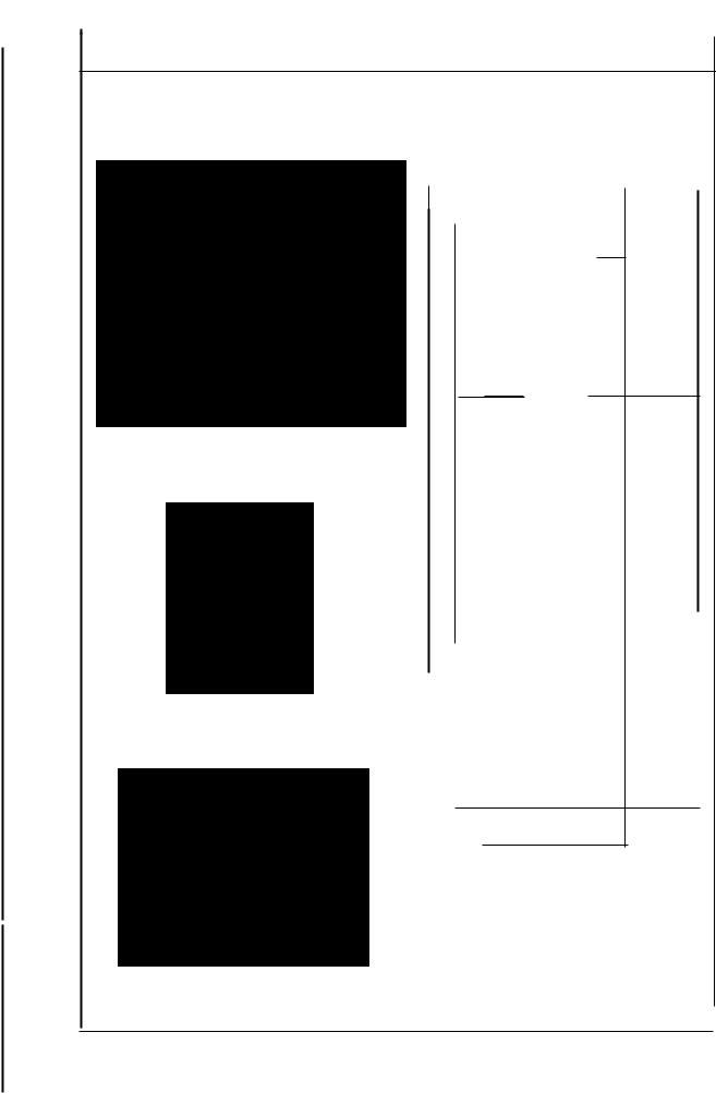
Standard Adjustment
(7) Positioning the upper looper holder
The distance between the bottom surface of the frame and the upper end of the upper looper holder pin 8 should be as shown below when the upper looper holder O is at the highest point of its stroke.
53mm t
0
l llt(tllfl(llltltl((l/1
Bottom surface of frame
•
|
|
|
|
|
|
|
|
|
|
|
|
|
|
|
|
|
(Unit: mm) |
|||
|
|
|
|
|
|
Model |
|
|
|
|
|
|
|
|||||||
|
|
|
|
|
|
|
|
|
Dimension& |
|||||||||||
-~ |
|
|
|
|
|
|
|
|
|
OAS |
156 |
45.0 |
|
|
||||||
|
|
|
|
|
|
|
|
|
|
|||||||||||
|
|
MOSLl.04S(R) |
-OA4 to OE4 |
·210 |
|
|
|
|
||||||||||||
|
|
|
|
6Ll.05S |
|
|
|
|
|
|
|
|
|
|||||||
|
|
|
|
|
|
|
|
|
|
|
|
|
|
|
|
|||||
|
|
|
|
|
|
|
|
|
006 |
|
|
|
3All. |
|
|
|
|
|||
1 |
|
|
|
|
|
|
|
|
OF4 |
|
3ll.O |
-- |
||||||||
8 |
|
|
|
|
|
|
|
|
|
|
|
|
|
|
|
|
462 |
|
|
|
'C |
MO- M04S(A)· OF6 |
-500 |
|
|
|
|
||||||||||||||
CS) |
|
|
|
|
||||||||||||||||
{:; |
|
|
|
|
|
|
|
|
|
OH4 |
|
SOM |
|
|
|
|
||||
~ |
|
|
|
|
|
|
|
|
|
|
|
|
|
|
||||||
m |
|
|
|
|
|
|
|
004 toOE4 |
|
46H |
482 |
|
|
|||||||
|
|
|
|
|
|
|
|
|
|
|
|
|
|
|
|
|||||
J |
MO- 6.!i.04S • |
OF6 |
|
|
|
|
|
|
|
|||||||||||
|
|
|
|
|
|
|
|
|
|
|
|
|
|
|
50H |
|
|
|
|
|
CS) |
|
|
|
|
|
|
|
B04 loBE4 |
|
|
|
|
|
|
|
|||||
~ |
|
|
MO· 6614S(R)· |
|
·3ll.7 |
47.3 |
|
|
||||||||||||
u |
|
|
|
|
|
|
|
B06toBE6 |
|
|
|
|
|
|
|
|||||
~BO~ to BFLi. 20H
|
.g |
MO· 6614S(R)· BE7 |
|
|
• 4.ll.H |
48.4 |
|
|
|
|||||||||||||||||||||
|
~ |
|
|
|
|
|
|
|
|
|
|
|
|
|
|
|
|
|
|
|
|
|
|
|
|
|
|
|
|
|
|
a, |
|
|
|
|
|
|
|
|
|
|
|
|
|
|
|
|
|
|
|
|
|
|
|
|
|
|
|
||
|
MO- |
6.ll.125 |
|
|
-CE4 |
|
|
|
·40H |
|
|
|
|
|
||||||||||||||||
|
> |
|
|
|
|
|
|
|
46.8 |
|
|
|||||||||||||||||||
|
0 |
|
|
|
|
|
|
|
|
|
|
|
|
|
|
|
|
|
|
|
|
|
|
|
|
|
|
|||
|
Cl> |
|
|
|
|
|
|
|
|
|
|
|
|
|
|
|
|
|
|
|
|
|
|
|
|
|
|
|
||
|
=a |
|
|
|
|
|
|
|
|
|
|
|
|
|
|
|
|
|
|
|
|
|
|
|
|
|
|
|
||
|
G) |
|
|
|
|
|
|
|
|
|
|
|
|
|
|
|
|
|
|
|
|
|
|
|
|
|
|
|
||
|
|
|
|
|
|
|
|
|
|
|
|
|
-507 |
|
|
|
|
|
|
|
|
|||||||||
|
Cl> |
MO- |
6ll.12S |
|
|
-DFG |
|
|
|
46.9 |
|
|
||||||||||||||||||
|
~ |
|
|
|
|
|
|
|
|
|
||||||||||||||||||||
|
(\I |
|
|
|
|
|
|
|
|
|
|
|
|
|
|
|
|
SOF |
|
|
|
|
|
|||||||
|
|
|
|
|
|
|
|
|
|
|
|
|
|
|
|
|
|
|
|
|
|
|
|
|
||||||
|
|
|
|
MO- |
66.16S(R)-6/\l\ |
|
|
|
|
3l:.O |
|
|
|
|
|
|||||||||||||||
|
|
|
|
|
|
|
|
|
|
|
|
|
|
46.2 |
|
|
|
|||||||||||||
|
|
|
|
|
|
|
|
|
|
|
|
|
|
|
|
500 |
|
|
|
|
|
|
||||||||
|
|
|
|
|
|
|
|
|
|
|
|
|
|
|
|
|
|
|
|
|
|
|
|
|||||||
|
|
|
|
|
|
|
|
|
|
|
|
|
|
|
|
|
|
|
|
|
|
|
|
|
|
|
|
|
|
|
|
GI |
|
|
|
|
|
|
|
|
|
|
BE4 |
|
|
|
|
|
|
|
|
|
|
|
|
|
|
|
|||
|
C |
|
|
|
|
|
|
|
|
|
|
|
|
|
|
|
|
4.ll.H |
|
|
|
|
|
|||||||
|
:c |
MO- |
6Ll.16S(R)- 006 |
|
|
|
|
48.2 |
|
|
||||||||||||||||||||
|
u |
|
|
|
|
|
|
|
|
|
|
|
|
|
|
|
|
5Ll.H |
|
|
|
|
|
|||||||
|
as |
|
|
|
|
|
|
|
|
|
|
|
|
|
|
|
|
|
|
|
|
|
||||||||
|
E |
|
|
|
|
|
|
|
|
|
|
Fll.D. |
|
|
|
|
|
|
|
|
|
|
|
|
|
|
|
|||
|
.c |
|
|
|
|
|
|
6616S{R) ·FD.6 |
|
|
|
|
|
|
|
|
|
|
|
|
|
|
|
|||||||
|
.B |
MO- |
|
|
-60H |
4B.4 |
||||||||||||||||||||||||
|
",ID |
|
|
|
|
|
|
|
|
|
|
|
|
|
|
|
|
|
|
|
|
|
|
|||||||
|
en |
|
|
|
|
|
|
|
|
|
|
|
|
|
|
|
|
|
|
|
|
|
|
|
|
|
|
|
||
|
2:- |
|
|
|
|
|
|
|
|
|
|
|
|
|
|
|
|
|
|
|
|
|
|
|
|
|
|
|
|
|
|
.S! |
|
|
MO- |
6943R |
|
|
-D.bD. |
|
|
·6.D.7 |
47.3 |
|
|
||||||||||||||||
|
a, |
|
|
|
|
|
|
|||||||||||||||||||||||
|
(/) |
|
|
|
|
|
|
|
|
|
|
. - |
|
|
|
|
|
|
|
|
|
|
|
|
|
|
|
|||
|
|
|
|
|
|
|
|
|
|
|
|
|
|
|
|
|
|
|
|
|
|
|
|
|
|
|
||||
|
|
|
|
|
|
|
|
|
|
|
|
|
|
|
|
|
|
|
|
|
|
|
|
|
|
|
||||
|
|
|
|
MO- |
6643S |
|
|
-D.66 |
|
|
-6.ti.H |
48.4 |
|
|
|
|||||||||||||||
|
|
|
|
|
|
|
|
|
|
|
|
|
|
|
|
|
|
|
|
|
|
|
|
|
|
|
|
|
||
|
|
|
|
|
|
|
|
|
|
|
|
|
|
|
|
|
|
|
|
|
|
|
|
|
|
- |
|
|||
|
|
|
|
|
|
|
|
|
|
|
|
|
|
|
|
|
|
|
|
|
|
|
|
|
|
|
||||
|
|
|
|
MO- |
|
|
|
|
|
-ON6 |
-301 |
|
|
|
|
|
|
|
|
|||||||||||
|
|
|
|
|
6903G |
|
|
|
|
512 |
|
|
||||||||||||||||||
|
|
|
|
|
|
|
|
|
|
|
|
|
|
|
|
|
|
|
|
|
|
|
|
|
|
|
|
|||
|
Cl> |
|
|
|
|
|
|
|
|
|
|
|
|
|
|
|
|
|
|
|
|
|
|
|
|
|
|
|
|
|
|
-~ |
|
|
|
|
|
|
|
|
|
|
|
|
|
|
|
|
|
|
|||||||||||
|
|
|
|
|
|
|
|
|
|
|
|
|
|
|
|
|
|
|
|
|
|
|
|
|
|
|
|
|
|
|
|
|
|
MO- |
6904G(J)-OF6 |
-700 |
|
|
|
50.7 |
|
|
|||||||||||||||||||
|
GI |
|
|
|
|
|
|
|
|
|
|
|
|
|
|
|
|
|
|
|
|
|
|
|
|
|
|
|||
|
Ill |
|
|
|
|
|
|
|
|
|
|
|
|
|
|
|
|
|
|
|
|
|
|
|
|
|
|
|
|
|
|
-,_ |
|
|
|
|
|
|
|
|
|
|
|
|
|
|
|
|
|
|
|
|
|
|
|
|
|
|
|
|
|
|
(!J |
|
|
|
|
|
|
|
|
|
|
|
|
|
|
|
|
|
|
|
|
|
|
|
|
|
|
|
|
|
|
|
|
MO- |
6905G |
|
-OM6 |
|
|
|
·1/:J.O |
|
|
|
|
|
|||||||||||||||
|
0 |
|
|
|
|
|
|
51.7 |
|
|
||||||||||||||||||||
|
0 |
|
|
|
|
|
|
|
|
|
|
|
|
|
|
|
|
|
|
|
|
|
|
|
|
|
|
|||
|
en |
|
|
|
|
|
|
|
|
|
|
|
|
|
|
|
|
|
|
|
|
|
|
|
|
|
|
|
|
|
|
C0 |
|
|
|
|
|
|
|
|
|
|
|
|
|
|
|
|
|
|
|
|
|
|
|
|
|
|
|
|
|
|
6 |
|
|
MO- |
6914G(J)-CH6 |
-700 |
|
|
|
|
|
|
|
|
||||||||||||||||
|
:E |
|
|
|
|
|
49.3 |
|
|
|
||||||||||||||||||||
|
|
|
|
,-. |
|
|
|
|
|
|
|
|
|
|
|
|
|
|
|
|
|
|
|
|
|
|
|
|
|
|
|
|
|
|
MO- |
6916G(J)·FD.6 |
-700 |
|
|
|
48.B |
||||||||||||||||||||
|
|
|
|
|
|
|
|
|
|
|
|
|
|
|
|
|
|
|
|
|
|
|
|
|
|
|||||
|
|
|
|
|
|
|
|
|
|
|
|
|
|
|
|
|
|
|
|
|
|
|
|
|
|
|
|
|
|
|
-16-
From the Library of Superior Sewing Machine & Supply LLC
|
|
|
|
|
|
Adjustment Procedures |
Results of Improper Adjustment |
|
|||
|
|||||
|
|
|
|||
1) Loosen the setscrew of upper looper ball arm O and setscrew |
o Inaccurately positioned upper |
|
|||
0 of the upper looper holder. |
looper |
holder will cause |
|
||
2) Adjust the clearances between upper looper bracket 8 and |
excessive projection of the |
|
|||
upper looper holder Oto approximately 0.2 mm respectively, |
upper looper, resulting in stitch |
|
|||
and tighten setscrew O of the upper looper holder. |
skipping, or other troubles. |
|
|||
(Make sure that the upper looper holder smoothly moves |
(Caution) To adiust the upper |
|
|||
together with upper looper shaft O.) |
|
||||
looper |
ball arm, take |
|
|||
3) Then determine dimension O from the bottom surface of the |
|
||||
dimension O as standard. |
|
||||
frame to the top surface of upper looper holder pin 8 before |
|
||||
Remember that the projecting |
|
||||
tightening the setscrew of upper looper ball arm 8. |
|
||||
amount and the height of the |
|
||||
(Caution) Replace upper looper holder 8 according to the |
|
||||
upper |
looper |
should |
|
||
needle gauge size. |
eventually be |
properly |
|
||
|
adjusted. So, confirm the |
|
|||
|
dimensions related to the |
|
|||
|
upper looper. |
|
|
|
|
|
|
|
|
|
|
|
|
|
|
|
|
-17-
l'I
:1
!I
II
I
l'
11
I
From the Library of Superior Sewing Machine & Supply LLC
I
II;.
~'
F
II
I
I
I
I!
ii
II
i
j
I
j
II
'1·ii
!
t
l
Standard Adjustment
(8)Positioning the upper looper
1)Height of the upper looper
The distance between the throat plate surface and the blade point of the looper should be as follows when the upper looper is at the extreme left of its travel.
|
|
|
|
|
|
|
|
|
|
|
|
|
|
|
|
|
|
|
|
|
|
|
|
|
|
|
|
{Unit: mm) |
|||||||
|
|
|
|
|
|
|
|
|
|
Model |
|
|
|
|
|
|
|
|
|
Dimension |
Ci) |
||||||||||||||
|
|
|
|
|
|
|
|
|
|
|
|
|
|
|
|
|
|
|
|
|
|
|
|||||||||||||
|
|
|
"g |
|
|
|
MO- |
|
|
|
|
|
|
|
|
|
660 |
|
|
|
|
|
|
|
|
|
|
|
|||||||
|
|
|
|
|
|
6804S(R)-L\L\L\ |
-6.66 |
|
|
|
|
|
|
|
|
|
|
|
|||||||||||||||||
|
|
|
"im |
|
|
11.0 |
|
|
|
||||||||||||||||||||||||||
|
|
|
is |
|
|
|
|
|
|
|
|
|
|
|
|
SOM |
|
|
|
|
|
|
|
|
|
|
|||||||||
|
|
|
a> |
ti |
|
|
|
|
|
|
|
|
|
|
|
|
|
|
|
|
|
|
|
|
|
|
|
|
|
|
|
|
|
||
|
|
|
MO- |
6604S |
-L\l::.l::. |
-l::.l::.H |
|
11.3 |
|
|
|
||||||||||||||||||||||||
|
|
|
'g~ |
|
|
|
|
|
|||||||||||||||||||||||||||
|
|
|
Q) |
|
|
|
|
|
|
|
|
|
|
|
|
|
|
|
|
|
|
|
|
|
|
|
|
|
|
|
|
|
|
|
|
|
|
|
:r |
|
|
|
|
|
|
|
|
|
|
|
|
|
|
|
|
|
|
|
|
|
|
|
|
|
|
|
|
|
|
|
|
|
|
|
|
|
|
MO- |
6/\05S |
-!:l.66 |
-6illi |
|
11.3 |
|
|
|
|||||||||||||||||||||
|
|
|
|
|
|
|
|
|
|
|
|
|
|
|
|
|
|
|
|
|
|
|
|
|
|
|
|
|
|
|
|
|
|||
|
|
|
|
|
|
|
|
MO- |
|
|
|
B04 to8E4 |
|
|
|
|
|
|
|
|
10.3 |
|
|
|
|||||||||||
|
|
|
~ |
|
|
|
Bli145lR)·sosto BES |
·307 |
|
|
|
|
|
|
|
|
|
|
|
|
|||||||||||||||
|
|
|
u |
|
|
|
|
|
|
|
|
|
|
|
|
|
|
|
|
|
|
|
|
|
|
|
|
|
|
|
|
|
|
|
|
|
|
|
0 |
|
|
|
|
|
|
|
|
|
|
|
|
|
|
|
|
|
|
|
|
|
|
|
|
|
|
|
|
|
|
|
|
|
|
|
|
|
|
|
|
|
|
|
BO6 to BF.6. 20H |
|
|
|
|
|
|
|
|
|
|
||||||||||||||
|
|
|
"C |
|
|
|
|
|
|
|
|
|
11.0 |
|
|
|
|||||||||||||||||||
|
|
|
Q) |
11) |
|
MO6614S(R)- E |
|
|
|
|
|
|
|
|
|
|
|
||||||||||||||||||
|
|
|
l> ~ |
|
|
|
|
|
|
|
|
|
|
|
|
|
|
|
|
|
|||||||||||||||
|
|
|
|
|
|
|
8 7 |
|
|
|
|
|
4!::.H |
|
|
|
|
|
|
|
|
|
|
||||||||||||
|
|
|
Q) |
u |
|
|
|
|
|
|
|
|
|
|
|
|
|
|
|
|
|
|
|
|
|
|
|
|
|
|
|
|
|
|
|
|
|
|
- |
|
co |
|
MO- |
6612S |
|
-CE4 |
|
-40H |
|
|
|
|
|
|
|
|
|
|
|||||||||||||
|
|
|
alE |
|
|
|
|
|
|
|
11.B |
||||||||||||||||||||||||
|
|
|
Q) |
|
|
|
|
|
|
|
|
|
|
|
|
|
|
|
|
|
|
|
|
|
|
|
|
|
|
|
|
|
|
|
|
|
|
|
C |
|
|
|
|
|
|
|
|
|
|
|
|
|
|
|
|
|
|
|
|
|
|
|
|
|
|
|
|
|
|
|
|
|
|
|
|
|
|
|
|
|
|
|
|
|
|
|
|
|
|
|
|
|
|
|
|
|
|
|
|
|
|
|
|
|
|
||
|
|
|
"' |
|
|
|
MO- |
6L\12S |
|
-DF6 |
507 |
|
|
|
11.0 |
|
|
|
|||||||||||||||||
|
|
|
|
|
|
|
|
|
|
|
|
|
|
|
|
|
|
||||||||||||||||||
|
|
|
-- |
|
|
|
|
|
|
|
|
|
|
|
|
|
50F |
|
|
|
|
|
|
|
|
|
|
||||||||
|
|
|
|
Cl> |
|
MO- |
6616S(R) |
-666 |
|
|
|
|
-L\60 |
|
11.0 |
|
|
|
|||||||||||||||||
|
|
|
|
|
|
|
|
|
|
|
|
|
|
|
|
|
|
|
|
|
|
|
|
|
|
|
|
|
|
|
|
||||
|
|
|
|
C |
|
|
|
|
|
|
|
|
|
|
|
|
|
|
|
|
|
|
|
|
|
|
|
|
|
|
|
|
|
|
|
|
|
|
:E |
|
|
|
|
|
BE4 |
|
4/\H |
|
|
|
|
|
|
|
|
|
|
||||||||||||||
|
|
|
|
u |
MO- |
~16S(A) - D06 |
|
|
11.3 |
|
|
|
|||||||||||||||||||||||
|
|
|
|
t'O |
|
|
5~H |
|
|
|
|
||||||||||||||||||||||||
|
|
|
|
E |
|
|
|
|
|
F6A |
|
|
|
|
|
|
|||||||||||||||||||
|
|
|
|
|
|
|
|
|
|
|
|
|
|
|
|
|
|
|
|
|
|||||||||||||||
|
|
|
|
|
|
|
|
|
|
|
|
|
|
|
|
|
|
|
|
|
|
|
|
|
|||||||||||
|
|
|
.c |
|
|
|
|
|
|
|
|
|
|
|
|
|
|
|
|
|
|
|
|
|
|
|
|
|
|
|
|
||||
|
|
|
|
j:1 |
MO· |
6616S(R) -Fb.6 |
|
-60H |
|
12.8 |
|
|
|
||||||||||||||||||||||
|
|
|
--C/l= |
|
|
|
|
|
|||||||||||||||||||||||||||
|
|
|
|
|
|
|
|
|
|
|
|
|
|
|
|
|
|
|
|
|
|
|
|
|
|
|
|
|
|
|
|||||
|
|
|
~~ |
|
|
MO- |
6943R |
-/\~6 |
|
|
|
|
·L\L\7 |
|
10.3 |
|
|
|
|||||||||||||||||
|
|
|
|
tU |
|
|
|
|
|
|
|
|
|
|
|
|
|
|
|
|
|
|
|
|
|
|
|
|
|
|
|
|
|||
|
|
|
Cl) |
MO- |
6643S |
·L\L\6 |
|
|
|
|
|
|
|
|
|
|
|
|
|
|
|
|
|
||||||||||||
|
|
|
|
·L\L\H |
|
11.0 |
|
|
|
||||||||||||||||||||||||||
|
|
|
|
|
|
|
|
|
|
|
|
|
|||||||||||||||||||||||
|
|
|
|
|
|
|
|
|
|
|
|
|
|
|
|
|
|
|
|
|
|
|
|
||||||||||||
|
|
|
0 |
|
|
|
MO- |
6903G |
-ON6 |
|
-3D1 |
|
13.6 |
|
|
|
|||||||||||||||||||
|
|
|
|
|
|
|
|
|
|
|
|||||||||||||||||||||||||
|
|
|
|
|
|
|
|
|
|
|
|
|
|
|
|
|
|
|
|
|
|
|
|
|
|
|
|
|
|
|
|
|
|
||
|
|
|
|
c:J |
|
|
|
|
|
|
|
|
|
|
|
|
|
|
|
|
|
|
|
|
|
|
|
|
|
|
|
|
|||
|
|
|
·c: |
MO- |
|
|
|
|
|
|
|
|
|
|
|
|
|
|
|
|
|
|
|
|
|
|
|
|
|
|
|||||
|
|
|
|
CD |
6904G{J) |
-OF6 |
|
•700 |
|
13.7 |
|
|
|
||||||||||||||||||||||
|
|
|
|
VJ |
|
|
|
|
|
||||||||||||||||||||||||||
|
|
|
~ |
|
|
|
|
|
|
|
|
|
|
|
|
|
|
|
|
|
|
|
|
|
|
|
|
|
|
|
|
|
|
||
|
|
|
|
|
|
|
|
|
|
|
|
|
|
|
|
|
|
|
|
|
|
|
|
|
|
|
|
|
|
|
|
|
|||
|
|
|
0 |
|
|
|
MO· |
6905G |
-OM6 |
·760 |
|
|
|
12.0 |
|
|
|
||||||||||||||||||
|
|
|
0 |
|
|
|
|
|
|
|
|
|
|||||||||||||||||||||||
|
|
|
0 |
|
|
|
|
|
|
|
|
|
|
|
|
|
|
|
|
|
|
|
|
|
|
|
|
|
|
|
|
|
|
|
|
|
|
|
O> |
|
|
|
|
|
|
|
|
|
|
|
|
|
|
|
|
|
|
|
|
|
|
|
|
|
|
|
|
||||
2) Longitudinal position of the upper looper |
|
co |
MO· |
6914G(J) |
-CHS |
-700 |
|
|
|
|
12.9 |
|
|
|
|||||||||||||||||||||
6 |
|
|
|
|
|
|
|
|
|
||||||||||||||||||||||||||
G) The clearance between the upper |
|
~ |
|
|
MO- |
6916G(J} |
-FL\6 |
-700 |
|
|
|
|
13.7 |
|
|
|
|||||||||||||||||||
|
|
|
|
|
|
|
|
|
|
|
|
|
|||||||||||||||||||||||
and lower loopers should be 0.1 to 0.2 mm |
|
|
|
|
|
|
|
|
|
|
|
|
|
|
|
|
|
|
|
|
|
|
|
|
|
|
|
|
|
|
|
|
|
|
|
|
|
|
|
|
|
|
|
|
|
|
|
|
|
|
|
|
|
|
|
|
|
|
|
|
|
|
|
|
|
|
|
|
|
||
when they cross with each other. |
|
|
|
|
|
|
|
|
|
|
|
|
|
|
|
|
|
|
|
|
|
|
|
|
|
|
|
|
|
|
|
|
|
||
®The clearance between the upper looper 8 and the needle should be oto 0.2 mm.
0.1 to 0.2mm ~--- l
7 __:s:
Lower looper
•
-18-
From the Library of Superior Sewing Machine & Supply LLC

Adjustment Procedures |
Results of Improper Adjustment |
||
|
|
|
|
1) Height of the upper looper |
o |
If the upper looper has been |
|
CD Set a hexagon screwdriver onto setscrew 8 at the end of upper |
|
positioned too high, an |
|
looper bracket O to adjust height f). |
|
excessive clearance will be |
|
@ When adjusting the height, pay attention also to the clearance |
|
produced between the upper |
|
produced between the upper looper and the lower looper at |
|
looper and the needle. As the |
|
the time of their crossing. |
|
result, the upper looper thread |
|
|
|
will fail to catch the needle |
|
|
|
thread, and stitch skipping |
|
|
|
occurs. |
|
|
o |
On the contrary, if the upper |
|
|
|
looper has been positioned too |
|
|
|
low, the needle point will hit the |
|
|
|
looper, causing needle |
|
|
|
breakage. Also the looper will |
|
|
|
touch other component when |
|
|
|
the presser foot goes up. |
|
...... ··
2) Longitudinal position of the upper looper |
o Excessive clearance will cause |
CD Loosen setscrew 8 at the top end of upper looper bracket O |
stitch skipping. |
to move upper looper O back or forth for positioning the |
o Insufficient clearance will cause |
clearance of 0.1 to 0.2 mm between the upper looper and the |
.the upper looper to come in |
lower looper at the time of their. crossing or the clearance of O |
contact with the lower looper. |
to 0.2 mm between upper looper O and the needle. |
|
-19-
From the Library of Superior Sewing Machine & Supply LLC
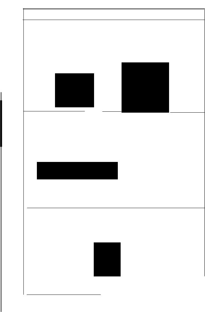
Standard Adjustment
(9) Adjusting the double chain looper
(Applicable only to M0-6.616S/6916R, G, J series)
1) Returning amount of the double chain looper
The distance between the needle center and the blade point of the double chain looper should be 1.5 to 2 mm when the_ looper is at the extreme left of its travel.
M0-691 SG, J series |
M0-661651 R series |
•
(63.4mm)
2) Longitudinal motion (Avoid motion)
The standard minor axis of the elliptical motion should be :
3.0 mm (M0-6~16S, R).
3.5 mm (M0-691 BG, J).
Note : The avoid motion should be adjusted in accordance with Needle No.
__,.,---------\
Marller (\. I
l-~ ~j
Marker Hole 8
3) Clearance between the double chain looper and the needle
The clearance should be 0.05 to 0.1 mm.
o.os to o.1 mm
-20-
From the Library of Superior Sewing Machine & Supply LLC

Adjustment Procedures |
Results of Improper Adjustment |
|
|
|
|
1) Returning amount of the double chain looper |
o |
Excessive return of the double |
(D Loosen setscrew 8 of double chain lopper driving arm O to |
|
chain looper will cause frequent |
make this adjustment. |
|
stitch skipping when filament |
@ Radius (I of the double chain looper driving arm 8 will be |
|
thread is used. |
63.4 mm when it is lowered until it comes in contact with stopper |
o |
Insufficient return of the double |
pint,. |
|
chain looper will cause frequent |
@ For M0-6916G,J type machines, radius® will be 63.2 mm. |
|
thread stitch skipping when a |
© Adjust the tilt of double chain looper with setscrew 8. Adjust |
|
spun thread is used. |
the tilt to 1.6 mm. |
|
|
2) Longitudinal motion (Avoid motion) |
|
o If the avoid motion is too large, |
|
(i) Open the cover of the adjusting hole on the rear of the frame. |
triangle stitch skipping will often |
||
loosen setscrew 0, and put a 02 rod in the hole. Now, make |
occur. |
||
the adjustment by turning the rod back and forth. |
|
|
|
Marker: This side |
|
|
Bad needle |
|
|
|
|
..... Minimum (for standard to thin needle) e } |
As observed |
----- ~entry |
|
. |
|
|
|
Marker : Far side |
. |
from this side |
Good needle |
· . |
|||
..... Maxunum (for ttuck needles) C) |
|
entry |
|
|
|
|
o Insufficient avoid motion will |
|
|
|
cause the needle point to hit the |
|
|
|
looper, producing scratches on |
|
|
|
the needle point or looper. |
3) Clearance between the double chain looper and the needle |
o Excessive clearance will cause |
|
(i) Temporarily tighten setscrew fJ in the double chain looper, |
frequent needle thread stitch |
|
and finely adjust the longitudinal position of the double chain |
skipping. |
|
looper. Adjust the clearance to 0.05 to 0.1 mm. |
'.:> Insufficient clearance will cause |
|
M0-6916S,R series only |
to looper to hit the needle, |
|
leading to needle breakage or |
||
® Turn fine adjustment screw O clockwise to move the double |
||
scratches on the looper blade |
||
chain looper away from the needle. |
||
point with consequent thread |
||
Turn it counterclockwise to move the double chain looper closer |
||
breakage. |
||
to it. |
||
|
-21 -
From the Library of Superior Sewing Machine & Supply LLC

Standard Adjustment
(1 O) Adjusting the height and clearance of the needle guard
1) For 1-needle or 2-needle overlock machine
Make needle guard e lightly come in contact with the top end of needle (bend needle by o to 0.05 mm) when the blade point of the lower looper reaches the needle center.
The clearance between needle guard Ci) and the needle is 0.1 mm when the needle is at the lowest point of its stroke.
The height of needle guard CD is 1 mm from the throat plate bottom surface.
Needle guard Q |
Needle guard @) |
(Traveling needle guard) |
Throat plate |
|
1 mm
•
2) For safely stitch machine
The safely stitch machine has four needle guards, e, CD, (9 and {i). The needle guards e and 6) are positioned in the same manner as those for the overlock machine.
The needle guard Cl should be positioned 5 mm below the throat plate bottom surface.
Throat plate
==-~--===~_;r-~;=::_J_
5mm
-22 -
From the Library of Superior Sewing Machine & Supply LLC

Adjustment Procedures
1) For 1-needle or 2-needle overlock machine
CD Adjust needle guard e with setscrews O in the needle guard so that it lightly comes in contact with the needle (bend needle by Oto 0.05 mm) when the blade point of the lower looper reaches the needle center.
®To adjust the clearance provided between needle guard CD and the
needle when the needle bar is at the IONest point of its stroke, loosen setscrews 8 in the needle guard support and tum needle guard CD to adjust the clearance to 0.1 mm.
@Adjust the height of needle guard CD to 1 mm from the throat plate bottom surface w~h setscrew 8 in the needle guard.
2)For safety stitch machine
©Loosen setscrews 8 in the needle guard, and adjust the clearance provided between needle guard Ci and the needle
so that it lightly comes in contact with the needle (bend needle by oto 0.05 mm).
®Adjust the installing height of needle guard (9 to 5 mm with setscrew 8 in the needle guard.
@Adjust the clearance provided between needle guard (!) and the needle to 0.1 mm with setscrews O.
(Caution) Check again the clearance provided between needle guard CD and the needle after adjusting the height of needle guard&.
Results of Improper Adjustment
oExcessively dose contact between the needle guard e and the needles will lead to needle bend or stitch skipping.
oA clearance left between the needle guard 6'and the needles will cause the looperblade point to come in contact with the needles, leading to needle or blade point breakage, or other troubles.
oIf the needle guard CD is too high, thread loops will be damaged with resultant stitch skipping. Also, doublechain loops will be affected, causing double chain stitch skipping.
oIf the needle guard t) is too low, the needle cooling felt will be lowered, resulting in deteriorated
effect of the cooling and needle guard.
oExcessive clearance between the needleguard@)and the needJe will cause stitch skipping due to needleshake. On the contrmy, insufficient clearance will cause the needle guards to catch the needles between them, leading to wear on the needle guards and scratches on the needles.
oIf the needle guard (tis too high, the needle thread loops will be damaged, and stitch skipping occur. If it is too low, the needle points will be crushed.
oIf the clearance between the needle guard 8 and the needles is too large, the doublechain boper blade pcint will come In contact with the needles, causing the breakage of the needles, causing the breakage of the needles or looper blade point.
Noclearance left between them will cause them tooome in excessively close contact with each other, and wear on the needle guard and
scratches on the needles will occur.
oExcessive clearance left between the needle guard CD and the needles will cause stitch skipping due to needle shake, and insufficient clearance wiU cause the needle guardsto catch the needles between them, leading to wear on the needle guards and scratches on the needles.
-23-
From the Library of Superior Sewing Machine & Supply LLC
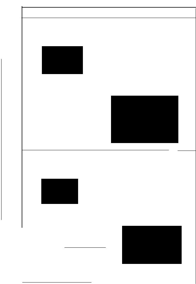
Standard Adjustment
(11) Adjusting the height of the feed dog
The height of main feed dog O from the top surface of the throat plate O should be as follows when
it is at its highest posion.
Needle A
8 entry
I
I
'
•
|
|
|
|
|
|
|
(Unit: mm) |
Model |
|
|
Dimension A |
||||
MO-6.600S Series |
|
- |
|
||||
|
1.0 |
||||||
MO-6904G Series |
|
1.3 |
|||||
MO-6914G Series |
|
|
|
1.2 |
|||
MO-6916G Series |
|
|
1.1 |
||||
|
|
|
|
|
|
|
|
Auxiliary feed dog 8 is 0.5 mm lower than main feed dog &.
-05mm
••
(12)Adjusting the tillt of the feed dog
Tilt of the feed dogs when the feed dogs |
When the feed dog iuts out the top surface of |
|||||||||||
have come up most. |
• |
|
|
the throat plate |
|
|||||||
|
|
|
|
|
|
Top surface of |
Feed dog is |
|||||
|
|
|
|
|
|
|
|
|
|
|
leveled. |
|
|
|
|
|
|
|
|
|
|
|
|
thethr\pla~ |
|
|
|
|
|
|
Front up |
|
|
|||||
|
|
|
|
|
|
|
|
|
|
|
|
N\MI\ |
|
|
|
|
|
|
|
|
|
(Unit: mm) |
|
|
|
Model |
Dimension A |
|
DimensionB |
|
|
|||||||
MO-6.t!:.0OS Series |
1.0 |
|
|
|
(1.2) |
|
|
|
||||
M0-6904G Series |
1.3 |
|
|
|
(1.5) |
|
|
|
||||
|
|
|
|
|
|
|
|
|
|
|
|
|
MO-6914G Series |
- 1.2 |
|
|
|
(1.4) |
|
|
|
||||
|
|
|
|
|
|
|
|
|
|
|||
MO-6916G Series |
|
|
|
|
|
|
|
|||||
1.1 |
|
|
|
(1.3) |
|
|
|
|||||
-24-
From the Library of Superior Sewing Machine & Supply LLC

|
AdJustment Procedures |
Results of Improper Adjustment |
|
|
|
|
|
|
|
|
1) Adjust the height of main feed dog 8 to dimension A with |
o |
If the feed dogs are too high, the |
|
|
setscrew 0. |
|
needles will be deflected and |
|
|
2) Adjust the height of differential feed dog 8 with setscrew O so |
|
broken when sewing heavy- |
|
|
|
|
||
|
that there is no difference in level between main feed dog 8 |
|
weight materials. The feed dogs |
|
|
and differential feed dog 8. |
|
will tend to suffer scratches |
|
|
|
|
||
|
3) Adjust the height of auxiliary feed dog 8 with setscrew O so |
|
when sewing light-weight |
|
|
that it is 0.5 mm lower than main feed dog 8. |
|
materials. Puckering will |
|
|
|
|
frequently occur. |
|
|
|
o |
If the feed dogs are too low, |
|
|
|
|
insufficient feed power will |
|
|
|
|
result |
|
|
|
o |
If the auxiliary feed dog is too |
|
|
|
|
||
|
|
|
high, chain-off thread will be |
|
|
|
|
often jammed. |
|
|
|
o If the main feed dog and |
|
|
|
|
|
differential feed dog are set at |
|
|
|
|
|
|
|
|
|
different heights, proper |
|
|
|
|
differential feeding action will be |
|
|
|
|
|
|
|
|
|
|
|
|
|
|
hindered. |
|
|
|
|
|
|
|
|
|
|
|
1)Use the tilt of the feed dog when it is in its highest position as a reference and adjust so that the feed dog is flush with the throat plate when the feed dog juts out the throat plate.
2)Feed bar shaft O consists of an eccentric shaft. Loosen setscrew t) to perform adjustment.
When the marker line is set at middle
.....The feed dog will be flat.
When the marker line is set at bottom
.....The feed dog will be tilted with its front up (in the arrowed direction).
When the marker line is set at top
.....The feed dog will be tilted with its front down.
(Caution) The marker line should be used just as the reference since it slightly differs with that of each machine due to the disparity of the components.
Confirm the accurate tilt of the feed dog by observing the
feed dog itself.
cWhen tilted with the front up Good material catching will be obtained.
oWhen tilted with the front down Uneven feed and puckering will be effectively prevented.
-25-
From the Library of Superior Sewing Machine & Supply LLC
 Loading...