


 Loading...
MB-1800 Series
INSTRUCTION MANUAL
|
CONTENTS |
|
!. SPECIFICATIONS ............................................................................................. |
1 |
|
@. NAME OF EACH COMPONENT ....................................................................... |
2 |
|
1. |
Name of the main unit ....................................................................................................................... |
2 |
#. INSTALLATION ................................................................................................. |
3 |
|
$. PREPARATION OF THE SEWING MACHINE .................................................. |
7 |
|
1. |
Attaching the needle ......................................................................................................................... |
7 |
2. |
Threading the machine ..................................................................................................................... |
7 |
%. OPERATION OF THE SEWING MACHINE....................................................... |
8 |
|
1. |
Names of the operation panel switches .......................................................................................... |
8 |
2. |
Pattern table....................................................................................................................................... |
9 |
3. |
Operating procedure of the operation panel (basic volume) ...................................................... |
10 |
4. |
Stitching without the crossover thread......................................................................................... |
11 |
5. |
Operating procedure of the operation panel (applied volume)................................................... |
11 |
6. |
How to use the memory switch...................................................................................................... |
13 |
^. ADJUSTMENT OF THE SEWING MACHINE ................................................. |
14 |
|
1. |
Thread tension adjustment ............................................................................................................ |
14 |
2. |
Adjustment of thread hauling amount .......................................................................................... |
14 |
3. |
Timing of thread tension release ................................................................................................... |
14 |
4. |
Adjustment of the thread tension guide on the face plate .......................................................... |
15 |
5. |
Adjustment of needle-to-looper relation ....................................................................................... |
15 |
6. |
Adjustment of the needle guide ..................................................................................................... |
16 |
7. |
Adjustment of the thread trimming mechanism........................................................................... |
16 |
8. |
Adjusting the height of the button clamp unit.............................................................................. |
17 |
9. |
Adjusting the work pressing force ................................................................................................ |
17 |
10. |
Adjustment of the button clamp stop lever .................................................................................. |
17 |
11. |
How to adjust the position of the feed origin ............................................................................... |
18 |
12. |
Installing the save button bar (accessory part) (MB-1800, MB-1800B) ...................................... |
19 |
13. |
Adjusting the wiper (Optional for MB-1800) ................................................................................. |
19 |
&. ATTACHMENTS .............................................................................................. |
20 |
|
1. |
Attachment for shank buttons (pearl buttons) (14617658, 14617757)........................................ |
21 |
2. |
Attachment for the first process of wrapped-around buttons (B24473720A0) ......................... |
21 |
3. |
Attachment for the second process of wrapped-around buttons (MAZ046010A0) .................. |
22 |
4. |
Attachment for snap (14617955) .................................................................................................... |
22 |
5. |
Attachment for metal buttons (14618052) ..................................................................................... |
23 |
*. ERROR LIST .................................................................................................... |
24 |
|
(. TROUBLES AND CORRECTIVE MEASURES ............................................... |
25 |
|
). OPTIONAL ....................................................................................................... |
26 |
|
1. |
Installing the without-crossover-thread device (Part No. : M85126300A0)................................ |
26 |
_. DRAWING OF THE TABLE ............................................................................. |
27 |

!. SPECIFICATIONS
1) |
Sewing area : |
X (lateral) direction 10 mm |
|
|
|
Y (longitudinal) direction 6.5 mm (0.2 mm pitch) |
|
2) |
Max. sewing speed : |
1,800 sti/min |
|
3) |
Feed motion of button clamp : |
Intermittent feed (2-shaft drive by stepping motor) |
|
4) |
Needle bar stroke : |
48.6 mm |
|
5) |
Needle : |
TQx7, TQx1 (TQx7 #16 at the time of delivery) |
|
6) |
Button size : |
10 to 28 mm |
|
7) |
Lift of button clamp : |
Standard 10 mm |
Max. 14 mm |
8) |
Memory of pattern data : |
EEP-ROM (32K byte) |
|
9)Enlargement/reduction system : Increase/decrease of stitch length system
10)Limitation of sewing speed : Sewing speed can be optionally limited to 400 to 1,800 sti/min
|
|
with the up/down key. (Adjustable in 100 sti/min unit) |
|||
11) |
Pattern selection function : |
1 to 99 patterns can be specified by selecting the pattern Nos. |
|||
12) |
Memory back-up : |
In case of a power interruption, the pattern being used will be |
|||
|
|
automatically stored in memory. |
|
||
13) |
Sewing machine motor : |
100W servo motor (direct-drive) |
|
||
14) |
Dimensions of machine head : |
W : 240 mm |
L : 550 mm |
H : 360 mm |
|
15) |
Mass : |
25 kg |
|
|
|
16) |
Power consumption : |
150 W |
|
|
|
17) |
Operating temperature range : |
5 to 35˚C |
|
|
|
18) |
Operating humidity range : |
35 to 85% (no dew condensation) |
|||
19) |
Line voltage : |
Rated voltage ±10% |
50/60 Hz |
||
20) |
Noise : |
- Equivalent continuous emission sound pressure level (LpA) at |
|||
|
|
the workstation :A-weighted value of 79.5 dB; (Includes KpA = |
|||
|
|
2.5 dB); according to ISO 10821- C.6.3 -ISO 11204 GR2 at |
|||
|
|
1,800 sti/min. |
|
|
|
Reduce the max. sewing speed in accordance with the sewing conditions.
SPECIFICATIONS 1
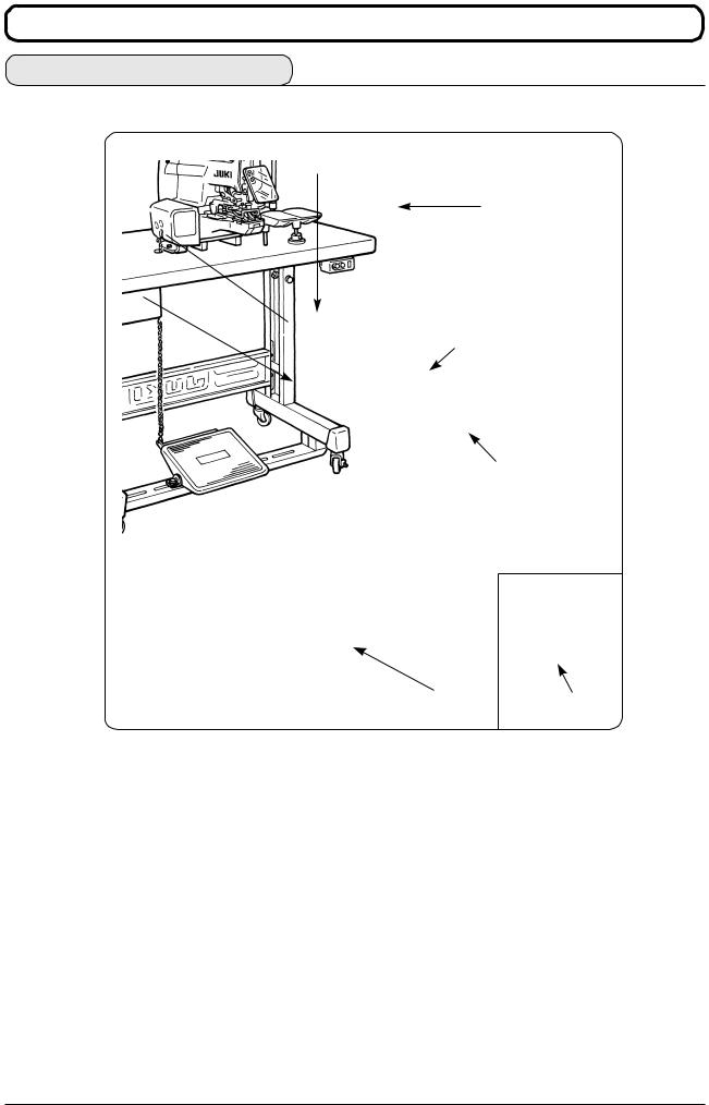
@. NAME OF EACH COMPONENT
1. Name of the main unit
1
4
2
3
5
6
8 7
The MB-1800 type machine consists of the sections listed in the following table.
1 |
Machine head |
|
|
2 |
Electrical components |
|
|
3 |
Operation panel switch |
|
|
4 |
Thread stand |
|
|
5 |
Button tray |
|
|
6 |
Power switch |
|
|
7 |
Power switch ( EU type) |
|
|
8 |
Starting pedal |
|
|
2NAME OF EACH COMPONENT

#. INSTALLATION
WARNING :
Be sure to perform the work with both hands when transporting the sewing machine.
(1) Installation of machine head
4
6
5
3
2
1
1)Place the machine head on the table and adjust the hole position of the table to the hole position of bed installing base 4. Pass spring washer 2 , and large washer 3 to bolt 1 supplied with the machine from the installing hole located at the bottom face of the table and set the bolt so that it comes out from the hole of bed installing base 4.
2)Put small washer 5 and nut 6 in order and tighten bolt 1 and nut 6.
(2)Attaching the bed cover and the rubber base
Tilt the machine head and fix bed cover 1 with screw 2. Next, insert rubber bases 3 into the pin protruding from the bottom face of the machine bed.
|
When tilting/raising the sewing machine |
1 |
head, hold the machine arm section by |
2 |
3 |
hand and slowly tilt it until it stops. |
|
||
|
|
INSTALLATION 3
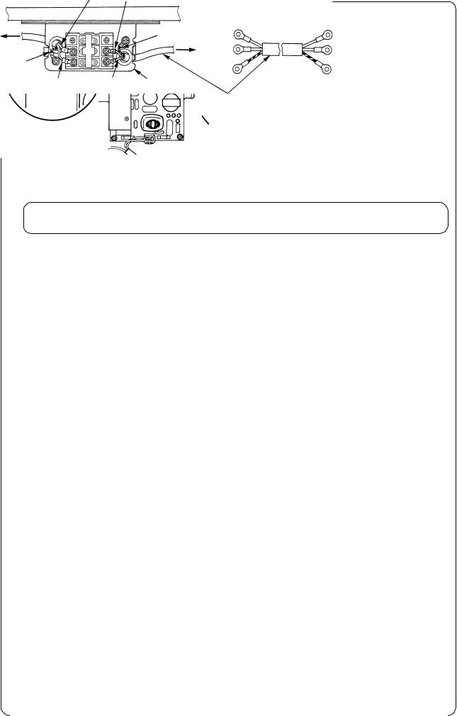
(3) Connection of power cord
1
2
1A
1)Tilt the sewing machine and put out cord 1 coming out from the sewing machine to the lower side from hole A in the table.
When tilting/raising the sewing machine head, hold the machine arm section by hand and slowly tilt it until it stops.
2)Install power switch box 2 on the bottom face of the table and fix cord 1 on the bottom face of the table with the staple supplied with the machine so that the cord can be connected to power switch box 2.
3)When using the sewing machine with the single phase 100 to 120V. (200 to 240V at the time of delivery)
It is necessary to change over the connector on the circuit board mounted on the sewing machine.
3 5
1
200V
4
2 |
100V |
|
4
1Remove electrical components cover guide 1
(This cover is required only for transportation or the like. It is not necessary to install it again.)
Next, remove electrical component cover 3 using setscrew 4.
2 Change over connector 5 located on PWR circuit board to the side of 100V.
• Connection of single phase 100 to 120V
Light blue Light blue |
|
|
|
|
||
Table |
|
|
|
|
|
|
Sewing |
|
|
|
|
AC 100V |
|
machine |
|
Green/yellow |
Brown |
|
||
head |
|
|
Light blue |
|
|
to |
|
|
|
|
|||
|
|
Plug |
|
AC 120V |
||
|
|
|
||||
|
|
|
|
|||
Green/yellow |
|
|
|
|
|
|
|
|
Green/yellow – GND |
||||
|
|
|
||||
Brown |
Brown |
Power switch |
|
|
|
|
|
|
|
Power cable |
|
|
|
|
|
|
|
|
|
|
|
|
|
|
|
|
|
4INSTALLATION
• Connection of single phase 200 to 240V
Light blue |
Light blue |
|
|
|
|
|
|
|
Table |
|
|
|
|
|
|
|
|
Sewing |
|
Green/yellow |
Brown |
|
AC 200V |
|||
machine |
|
|
||||||
head |
|
|
Light blue |
|
|
to |
||
|
|
|
|
|||||
|
|
|
AC240V |
|||||
|
|
Plug |
|
|||||
|
|
|
|
|
|
|||
Green/yellow |
|
|
|
|
|
|
|
|
|
|
Green/yellow - GND |
||||||
|
|
|
||||||
Brown |
Brown Power switch |
|
|
|
|
|
|
|
|
|
|
Power cable |
|
|
|||
• Connection of 3-phase 200 to 240V |
|
|
|
|
|
|
||
Light blue |
Red |
|
|
|
|
|
|
|
Table |
|
|
|
|
|
|
|
|
Sewing |
|
Green |
Red |
|
|
AC 200V |
||
|
|
|
|
|||||
machine |
|
|
|
|
|
|||
|
|
White |
|
|
|
|
to |
|
head |
|
|
|
|
|
|||
|
|
|
|
|
|
|||
|
|
|
|
|
|
AC 240V |
||
|
|
Plug |
Black |
|
|
|
||
Green/yellow |
|
|
|
|
|
|||
|
|
|
|
|
||||
|
|
|
|
|
|
|
|
|
Brown |
White |
Black |
Green |
|
GND |
|||
|
||||||||
|
|
|
|
|
|
|||
|
|
Power switch |
Power cable |
|
|
|||
|
|
|
|
|
||||
When voltage of 100 to 120V is used, connect the input change-over connector of CN32 mounted on the PWR circuit board to 100V side.
When voltage of 200 to 240V is used, connect the input change-over connector to 200V side. If the setting of CN32 connector is mistaken, the control box is likely to be broken.
Never use under the wrong voltage and phase.
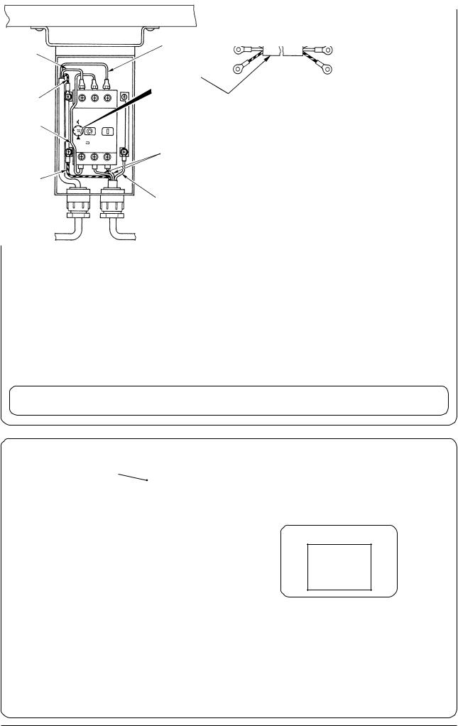
(4) Power switch
Table
Light blue |
Brown |
|
|
|
|
|
|
|
Ampere set value |
||
|
|
200 V |
|
|
|
|
|
Green/Yellow |
|
220 V |
2.0 A |
|
230 V |
||
|
|
|
|
|
|
|
|
Black |
|
240 V |
|
Black
Green/Yellow
Light blue
Sewing machine head |
Plug |
INSTALLATION 5
(5) Attaching the needle bar cover
1
2
(6) Installing the eye protection cover
1
WARNING :
Turn OFF the power before starting the work so as to prevent accidents caused by abrupt start of the sewing machine.
Loosen setscrew 2 and fix needle bar cover 1 supplied with the machine as shown in the figure.
WARNING :
Be sure to attach this cover to protect the eyes from the dispersion of needle breakage.
Turn OFF the power before starting the work so as to prevent accidents caused by abrupt start of the sewing machine.
Be sure to install eye protection cover 1 and use the sewing machine.
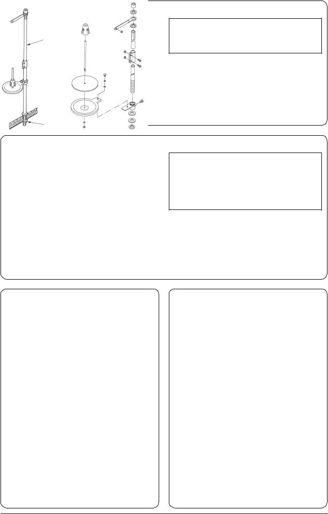
(7) Installing the thread stand |
(8) Attaching the button tray |
2
1
1)Assemble the thread stand unit, and set it in the hole located at the upper right of the table.
2)Tighten locknut 1 to fix the thread stand.
3)For ceiling wiring, pass the power cord through spool rest rod 2.
4
1
2
3
1)Fix base 1 on the table with wood screw 2.
2)Insert the button tray 4 in the hole of base 1 and fix with setscrew 3.
6INSTALLATION

$. PREPARATION OF THE SEWING MACHINE
1. Attaching the needle
WARNING :
Turn OFF the power before starting the work so as to prevent accidents caused by abrupt start of the sewing machine.
The needle of TQx7 #16 is attached to the sewing machine.
|
1 |
Loosen setscrew 1 and hold needle 2 with its |
|
|
|
|
|
long groove facing to this side. Insert needle 2 up |
|
|
into the needle hole in the needle bar until it comes |
2 |
|
in contact with the deepest end of the needle hole |
|
|
|
|
|
and tighten setscrew 1. |
2. Threading the machine
WARNING :
Turn OFF the power before starting the work so as to prevent accidente caused by adrupt start of the sewing machine.
Thread the machine in the order as illustrated.
Finally, pass the thread through the needle eye by approximately 60 to 70 mm.
|
|
|
|
5 |
3 |
2 |
|
|
|
|
|
||
|
|
|
|
|
|
|
|
|
9 |
|
|
|
1 |
|
|
|
|
|
|
|
!1 |
|
|
|
|
|
|
!3 |
!2 |
8 |
6 |
4 |
|
|
|
|
|
|
|||
|
|
!0 |
7 |
|
|
|
|
|
|
|
|
|
|
|
|
|
|
|
|
1 |
|
|
|
|
|
|
2 |
!5 |
|
!4 |
5 |
4 |
|
|
|
|
6 |
|
|
|
|
!6 |
|
|
|
|
|
|
3
7
PREPARATION OF THE SEWING MACHINE 7
Loading...