


 Loading...
JUKI MF-7900D/UT55, MF-7900D/UT57, MF-7900D/UT56, MF-7900/UT55, MF-7900/UT57 Instruction Manual
...MF-7900(D)/UT55,56,57 INSTRUCTION MANUAL
|
|
No.01 |
|
|
|
2 |
|
70002031 |
|
|
|
CONTENTS
!. SPECIFICATIONS........................................................................................................... |
1 |
|
@. AT THE BEGINNING....................................................................................................... |
1 |
|
#. Installing the accessories................................................................................ |
2 |
|
1. |
Installing the presser lifting cylinder............................................................................................. |
2 |
2. |
Installing the air regulator............................................................................................................... |
2 |
3. |
Installation and setting SC-921...................................................................................................... |
3 |
|
(1) Installing the SC-921 on the table ( Table-mount type )............................................................................. |
3 |
|
(2) Installing the SC-921 on the table ( Semi-submerged type )..................................................................... |
3 |
|
(3) Connecting the cords................................................................................................................................... |
4 |
|
(4) Setting procedure of the machine head...................................................................................................... |
5 |
|
(5) Setting the lower stop position of the needle bar...................................................................................... |
6 |
$. AIR PIPING DRAWING................................................................................................... |
7 |
|
1. |
Piping of the thread trimmer device (UT57).................................................................................. |
7 |
2. |
Piping of the thread trimmer device (UT55).................................................................................. |
8 |
3. |
Piping drawing for air blow (UT56)................................................................................................ |
9 |
4. |
Adjusting the air regulator.............................................................................................................. |
9 |
%. THREADING THE MACHINE HEAD............................................................................ |
10 |
|
^. Adjusting the looper thread trimmer mechanism................................. |
11 |
|
1. |
Adjusting the thread trimmer air cylinder.................................................................................... |
11 |
2. |
Adjusting the Lower knife............................................................................................................. |
12 |
3. |
Adjusting the position of clamp pressure adjusting spring...................................................... |
12 |
4. |
Adjusting the knife engagement and the knife pressure adjusting spring.............................. |
12 |
5. |
Adjusting the pressure of clamp spring...................................................................................... |
12 |
6. |
Initial position of the looper thread trimmer mechanism.......................................................... |
13 |
7. |
Adjusting the stopper.................................................................................................................... |
13 |
8. |
Adjusting the height of the lower knife....................................................................................... |
13 |
9. |
Adjusting the lower knife holder guide....................................................................................... |
13 |
10. |
Adjusting the longitudinal position of the blade point of lower knife...................................... |
14 |
11. |
Adjusting the thread trimmer sensor........................................................................................... |
14 |
12. |
Adjusting the speed of looper thread trimmer............................................................................ |
14 |
&. Adjusting the thread release mechanism................................................. |
15 |
|
1. |
Adjusting the disk-rise.................................................................................................................. |
15 |
2. |
Adjusting the thread release hook............................................................................................... |
15 |
*. Adjusting the top covering thread trimmer mechanism.................... |
16 |
|
1. |
Adjusting the engagement of knives........................................................................................... |
16 |
2. |
Adjusting the pressure of clamp spring...................................................................................... |
16 |
3. |
Adjusting the position of the blade point of moving knife........................................................ |
16 |
4. |
Adjusting the speed of moving knife........................................................................................... |
17 |
(. Adjusting the air-blow wiper (UT56)............................................................. |
18 |
|
1. |
Installing the air-blow wiper......................................................................................................... |
18 |
2. |
Adjusting the air-blow wiper......................................................................................................... |
18 |
). Adjusting the needle thread wiper (UT55)................................................. |
19 |
|
1. |
Adjusting the clamp spring.......................................................................................................... |
19 |
2. |
Installing the needle thread wiper................................................................................................ |
19 |
_. MAINTENANCE............................................................................................................ |
20 |
|
1. |
Cleaning the motor fan.................................................................................................................. |
20 |

!. SPECIFICATIONS
Model name |
High-speed, cylinder-bed coverstitch machine |
Semi-dry head, high-speed, cylinder-bed |
|
|
coverstitch machine |
Model |
MF-7900 series |
MF-7900D series |
Stitch type |
ISO standard 406, |
407, 602, and 605 |
Example of application |
Hemming and covering for knits and general knitted fabrics |
|
Sewing speed |
Max. 6,500 sti/min (at the time of intermittent operation) |
Max. 5,000 sti/min (at the time of intermittent operation) |
|
V-belt type |
V-belt type |
|
Max. 6,000 sti/min (at the time of intermittent operation) |
Max. 5,000 sti/min (at the time of intermittent operation) |
|
Direct-drive type |
Direct-drive type |
|
Speed of stitch at the delivery: |
Speed of stitch at the delivery: |
|
4,500 sti/min (at the time of intermittent operation) |
4,000 sti/min (at the time of intermittent operation) |
Needle gauge |
3-needle...... 5.6 mm and 6.4 mm |
|
|
2-needle...... 3.2 mm, 4.0 mm and 4.8 mm |
|
Differential feed ratio |
1 : 0.9 to 1 : 1.8 (stitch length : less than 2.5 mm) |
|
|
(1 : 0.6 to 1 :1 .1, when the differential link hinge screw is changed) |
|
|
Micro-differential feed adjustment mechanism is provided. (Micro-adjustment) |
|
Stitch length |
0.9 mm to 3.6 mm (can be adjusted up to 4.5 mm) |
|
Needle |
UY128GAS #9S to #14S (standard #10S) |
UY128GAS #9S to #12S (standard #10S) |
Needle bar stroke |
31mm (33 mm when the eccentric pin is changed over) |
|
Dimensions |
(Height) 450 x (Width) 456 x (Length) 299 |
|
Weight |
45 kg (With pneumatic type thread trimmer) , 42 kg |
|
Lift of presser foot |
8 mm (needle gauge : 5.6 mm without top covering), and 5 mm (with top covering) |
|
|
Micro-lifter mechanism is provided. |
|
Feed adjustment |
Main feed............... dial type stitch pitch adjustment method |
|
method |
Differential feed...... lever adjustment method (micro-adjustment mechanism is provided.) |
|
Looper mechanism |
Spherical rod drive method |
|
Lubricating system |
Forced lubrication method by gear pump |
|
Lubricating oil |
JUKI GENUINE OIL 18 |
|
Oil reservoir capacity |
Oil gauge lower line : 600 cc to upper line : 900 cc |
|
Installation |
Table-mount type, Semi-submerged type |
|
Noise |
- Equivalent continuous emission sound pressure level |
- Equivalent continuous emission sound pressure level |
|
(LpA) at the workstation: |
(LpA) at the workstation: |
|
A-weighted value of 79.5 dB; (Includes KpA = 2.5 dB); |
A-weighted value of 76.5 dB; (Includes KpA = 2.5 dB); |
|
according to ISO 10821- C.6.2 -ISO 11204 GR2 at |
according to ISO 10821- C.6.2 -ISO 11204 GR2 at |
|
4,500 sti/min. |
4,000 sti/min. |
@. AT THE BEGINNING
Remove fixed band 1 for transportation before setting up the sewing machine.
1

– –
#. Installing the accessories
WARNING :
To protect against possible personal injury due to abrupt start of the machine, be sure to start the following work after turning the power off and ascertaining that the motor is at rest.
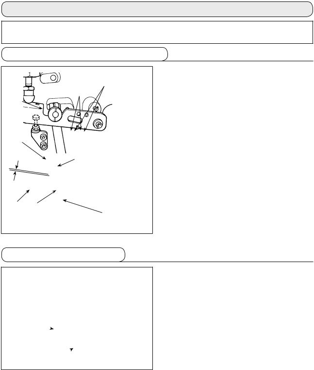
1. Installing the presser lifting cylinder
4,7
3
1
8 |
|
1 to 2mm |
9 |
2 5
6
1)Install presser lifting cylinder asm. 1 to the sewing machine with screws 3, washers 4 and spring washers 7.
2)Tighten screw 3 in such manner that a clearance of 1 to 2 mm is provided between cap 9 at the top end of presser lifting cylinder asm. 1 and presser lifting lever 2.
If the clearance cannot be adjusted to 1 to 2 mm, adjust the height of nut 8 and cap 9 to obtain the correct clearance between the cap and lever.
3)Adjust the height of screw 5 referring to the Instruction Manual for MF-7900 (^-14. Adjusting the presser foot lift), and tighten nut 6.
4)Stroke of cylinder asm. 1 is 30 mm. Make sure that presser lifting lever 2 comes in contact with screw 5 within the range of cylinder stroke.
2. Installing the air regulator
1) Install air regulator asm. 1 under the table with wood screws 2.
2
1
––
3.Installation and setting SC-921
(1)Installing the SC-921 on the table ( Table-mount type )
*The instructions apply to the case the control box is installed on the table of the MF-7900(D).
To use any other machine head, install the control box on the table referring to the Instruction Manual for the main body of the relevant sewing machine.
1
|
1 |
Fig. A |
|
Convex |
6 |
washer |
|
Spring |
|
washer Hexagonal nut |
5 |
6
Fig. B
4
2
1)Install control box 2 on the table with mounting bolt asm. 1 supplied with the unit.
At this time, insert the nuts and washers supplied with the unit as illustrated in Figure A so that the support plates and the control box 2 are securely fixed.
2)Install the control box 2 (or the one equipped with a small sized motor unit) on the table. Then, install the sewing machine head on the table. (Refer to the Instruction Manual for the sewing machine.)
3)Install the mounting plate on the CP-18 panel 5 with four tapping screws 4 supplied with the unit. At this time, take care not to allow the cable to be caught under the mounting bracket.
(Install the CP-18 on the table as illustrated in Fig. B.)
4)Install CP-18 panel 5 on the table with wood screw 6.
(2) Installing the SC-921 on the table ( Semi-submerged type )
1
!0
8
7
 !1
!1
9
1)Install right and left support plates 7 and two rubber seats 8 of the respective support plates.
2)Install control box mounting plate 9 on the control box with four screws !0.
3)Install the parts assembled in Step 2) on the underside of support plates 7 with four screws
!1.
4)Install support plates 7 and the control box 2 on the table with mounting bolts asm. 1 supplied with the unit. At this time, insert the nuts and washers supplied with the unit as
illustrated in Figure A so that the support plates and the control box 2 are securely fixed.
*The steps of procedure from the next one and beyond are same with those for the table-fixed type machine head.
2
––

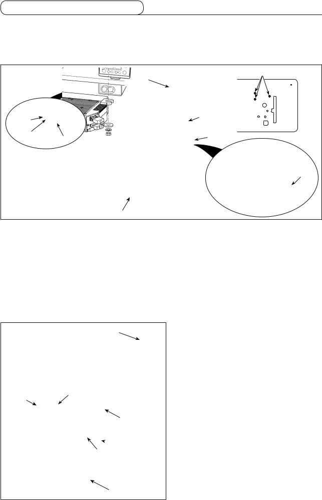
(3) Connecting the cords
B
2
2) Loosen screw B in cover 2 with a screwdriver to open the cover.
1
 A
A
1)Pass cords 1 of the thread trimming solenoid, reverse-stitching solenoid, etc. and the cord from the motor through hole A in the table to route them down under the machine table.
|
|
|
3) |
Connect 14P code 3 coming |
!0 8 |
!2 6 7 !4 |
|||
|
|
|
|
from the machine head to |
|
|
|
4) |
connector 6 (CN36). |
|
|
|
Insert 3P cord 9 coming |
|
|
|
|
|
from the machine head into |
|
|
|
5) |
connector !0(CN42). |
|
|
|
Insert presser foot lifter cord 2P |
|
|
!3 |
6) |
4 into connector 7 (CN37). |
|
|
|
|
Connect connector 5 coming |
|
|
|
|
|
from the motor to connector 8 |
9 |
|
4 |
|
(CN30) on the circuit board. |
|
|
|||
5 |
|
|
|
|
!13 |
|
|
||
|
|
|
||
|
|
|
|
|
7)Insert pedal sensor cable !1into connector !2(CN34).
8)Insert motor fan cord !3into connector !4.
Be sure to securely insert the respective connectors after checking the inserting directions since all connectors have the inserting directions. (When using a type with lock, insert the connectors until they go to the lock.) The sewing machine is not actuated unless the connectors are inserted properly. In addition, not only the problem of error warning or the like occurs, but also the sewing machine and the control box are damaged.
[Connecting the connector for the operation panel]
!6
!5
The connector for the operation panel is provided. Paying attention to the orientation of the connector !5, connect it to connector (CN38) !6located on the circuit board. After the insertion, securely lock the connectors to prevent them from coming off easily.
Be sure to turn OFF the power before connecting the connector.
––

(4) Setting procedure of the machine head
For the operation panel other than CP-18, refer to the Instruction Manual for the operation panel to be used for the setting procedure of the machine head.
1 2 3 4
1 2 3 4
1)Call function setting No. 95.
2)The type of machine head can be selected by pressing  switch 3 (
 switch 4).
*Refer to the "MACHINE HEAD LIST" on the separate sheet or the Instruction Manual for the machine head of your sewing machine for the type of the machine head.
Type of machine head |
Model name |
|
|
|
MF-7900/UT55 |
|
|
F79 |
MF-7900/UT56 |
|
|
|
MF-7900/UT57 |
|
|
|
MF-7900D/UT55 |
|
|
F79d |
MF-7900D/UT56 |
|
|
|
MF-7900D/UT57 |
|
|
3) After selecting the type of machine head, by pressing  switch 1 (
 switch 2), the step proceeds to
96 or 94, and the display automatically changes to the contents of the
setting corresponding with the type of machine head.
1 2 3 4
––
Loading...