


 Loading...
ENGLISH
INSTRUCTION MANUAL
i

|
CONTENTS |
|
. EXPLANATION OF LK-1900A, COMPUTER-CONTROLLED |
|
|
HIGH-SPEED BARTACKING MACHINE .................................................................... |
1 |
|
[1] SPECIFICATIONS .................................................................................................................................. |
1 |
|
[2] CONFIGURATION .................................................................................................................................. |
2 |
|
1. |
Names of main unit .......................................................................................................................................... |
2 |
2. |
Names and explanation of switches on the operation panel ....................................................................... |
3 |
[3] INSTALLATION ...................................................................................................................................... |
4 |
|
1. |
Installing the electrical box ............................................................................................................................. |
4 |
2. |
Attaching the connecting rod ......................................................................................................................... |
4 |
3. |
Installing the head support rod ...................................................................................................................... |
4 |
4. |
Installing and connecting the power switch.................................................................................................. |
5 |
5. |
Installation of the sewing machine head ....................................................................................................... |
6 |
6. |
Installing the drain receiver and the head support rubber .......................................................................... |
6 |
7. |
Safety switch .................................................................................................................................................... |
7 |
8. |
Tilting the sewing machine head .................................................................................................................... |
7 |
9. |
Installing the operation panel ......................................................................................................................... |
8 |
10. |
Connecting the cord ........................................................................................................................................ |
9 |
11. |
Installing the motor cover ............................................................................................................................. |
10 |
12. |
Managing the cord ......................................................................................................................................... |
11 |
13. |
Installing the eye protection cover ............................................................................................................... |
11 |
14. |
Installing the thread stand ............................................................................................................................ |
12 |
[4] OPERATION OF THE SEWING MACHINE .......................................................................................... |
13 |
|
1. |
Lubrication ..................................................................................................................................................... |
13 |
2. |
Attaching the needle ...................................................................................................................................... |
13 |
3. |
Threading the machine head ........................................................................................................................ |
14 |
4. |
Installing and removing the bobbin case .................................................................................................... |
14 |
5. |
Installing the bobbin ...................................................................................................................................... |
15 |
6. |
Adjusting the thread tension ........................................................................................................................ |
15 |
7. |
Adjusting the thread take-up spring ............................................................................................................ |
16 |
8. |
Example of the thread tension ...................................................................................................................... |
17 |
[5] OPERATION OF THE SEWING MACHINE (BASIC) ........................................................................... |
16 |
|
1. |
Item data setting ............................................................................................................................................ |
16 |
2. |
Checking the contour of a sewing pattern .................................................................................................. |
19 |
3. |
Sewing ............................................................................................................................................................ |
20 |
4. |
Change to the other sewing pattern ............................................................................................................. |
20 |
5. |
Winding a bobbin ........................................................................................................................................... |
21 |
6. |
Thread clamp device ..................................................................................................................................... |
22 |
[6] OPERATION OF THE SEWING MACHINE (ADVANCED) .................................................................. |
24 |
|
1. |
Performing sewing using the pattern keys ( , , , and ) ....................................................... |
24 |
2. |
Performing sewing using the combination function .................................................................................. |
27 |
3. |
Performing sewing using the “bobbin thread counter” ............................................................................. |
29 |
4. |
How to use the temporary stop .................................................................................................................... |
29 |
5. |
Setting the pattern thread tension ............................................................................................................... |
30 |
6. |
Cautions in operation .................................................................................................................................... |
31 |
[7] MAINTENANCE ................................................................................................................................... |
31 |
|
1. |
Adjusting the height of the needle bar ........................................................................................................ |
31 |
2. |
Adjusting the needle-to-shuttle relation ...................................................................................................... |
32 |
3. |
Adjusting the lift of the work clamp foot ..................................................................................................... |
33 |
4. |
The moving knife and counter knife............................................................................................................. |
33 |
5. |
Needle thread clamp device .......................................................................................................................... |
34 |
6. |
Adjustment of the wiper ................................................................................................................................ |
34 |
7. |
Draining waste oil .......................................................................................................................................... |
35 |
8. |
Amount of oil supplied to the hook .............................................................................................................. |
35 |
9. |
Replacing the fuse ......................................................................................................................................... |
35 |
10. |
Changing the voltage of 100/200V ................................................................................................................ |
36 |
11. |
Replenishing the designated places with grease ....................................................................................... |
37 |
[8] HOW TO USE THE MEMORY SWITCH ............................................................................................... |
38 |
|
1. |
Start and change of the memory switch ...................................................................................................... |
38 |
2. |
Example of the memory switch setting ....................................................................................................... |
38 |
3. |
Table of functions of the memory switch .................................................................................................... |
42 |
iii
[9] OTHERS ............................................................................................................................................... |
45 |
|
1. |
Setting the DIP switch ................................................................................................................................... |
45 |
2. |
Table of the standard pattern specifications ............................................................................................... |
46 |
3. |
Table of the standard patterns ...................................................................................................................... |
47 |
4. |
Table of the work clamp foot ......................................................................................................................... |
49 |
5. |
LK-1900 data ROM ......................................................................................................................................... |
51 |
6. |
Connection of the optional pedal ................................................................................................................. |
51 |
7. |
Error list .......................................................................................................................................................... |
52 |
8. |
Troubles and corrective measures (sewing conditions) ............................................................................ |
55 |
9. |
Table of the optional parts ............................................................................................................................ |
57 |
2. EXPLANATION OF THE LK-1901A, COMPUTER-CONTROLLED HIGH-SPEED |
|
|
EYELET BUTTONHOLE BARTACKING MACHINE ................................................. |
59 |
|
1. |
Specifications ................................................................................................................................................. |
59 |
2. |
Installation of the sewing machine and preparation of the operation ...................................................... |
59 |
3. |
Adjustment of the material closing amount ................................................................................................ |
60 |
4. |
Adjustment of the lift of the work clamp foot .............................................................................................. |
60 |
5. |
Adjustment of the pressure of the work clamp unit ................................................................................... |
61 |
6. |
Setting of the material closing operation .................................................................................................... |
61 |
7. |
Selection and confirmation of the sewing patterns .................................................................................... |
62 |
3. EXPLANATION OF THE LK-1902A, COMPUTER-CONTROLLED HIGH-SPEED |
|
|
BELT-LOOP ATTACHING MACHINE........................................................................ |
63 |
|
1. |
Specifications ................................................................................................................................................. |
63 |
2. |
Installation of the sewing machine and preparation of the operation ...................................................... |
63 |
3. |
Threading the machine .................................................................................................................................. |
63 |
4. |
Selection and confirmation of the sewing patterns .................................................................................... |
64 |
5. |
Combination of the work clamp foot and the feed plate ............................................................................ |
64 |
4. EXPLANATION OF THE LK-1903A, COMPUTER-CONTROLLED |
|
|
HIGH-SPEED LOCKSTITCH BUTTON SEWING MACHINE ................................... |
65 |
|
1. |
Specifications ................................................................................................................................................. |
65 |
2. |
Installation of the sewing machine and preparation of the operation ...................................................... |
65 |
3. |
Needle and thread .......................................................................................................................................... |
65 |
4. |
Various sewing modes .................................................................................................................................. |
66 |
5. |
Position of the button clamp jaw lever ......................................................................................................... |
67 |
6. |
Adjusting the feed plate ................................................................................................................................ |
68 |
7. |
Adjusting the button clamp jaw lever .......................................................................................................... |
68 |
8. |
Adjusting the lifting amount of the button clamp ....................................................................................... |
69 |
9. |
Adjustment of the pressure of the work clamp unit ................................................................................... |
69 |
10. |
Adjustment of the wiper spring .................................................................................................................... |
70 |
11. |
Installing the save button bar (accessory part) .......................................................................................... |
70 |
12. |
Model classification according to the button size ...................................................................................... |
71 |
13. |
Attaching the shank botton (optional) ......................................................................................................... |
72 |
5. DRAWING OF THE TABLE ...................................................................................... |
76 |
|
iv

. EXPLANATION OF LK-1900A, COMPUTER-CONTROLLED HIGH-
SPEED BARTACKING MACHINE
[1] SPECIFICATIONS
1) |
Sewing area ................................................. |
X (lateral) direction 40 mm Y (longitudinal) direction 30 mm |
2) |
Max. sewing speed ...................................... |
* 3,000 rpm |
|
|
(When sewing pitches are less than 5 mm in X-direction |
|
|
and 3.5 mm in Y -direction.) |
3) |
Stitch length ................................................. |
0.1 to 10.0 mm (adjustable in 0.1 mm step) |
4) |
Feed motion of work clamp foot ................... |
Intermittent feed (2-shaft drive by stepping motor) |
5) |
Needle bar stroke ........................................ |
41.2 mm |
6) |
Needle.......................................................... |
DP x 5, DPx17 |
7) |
Lift of work clamp foot .................................. |
13 mm (standard) Max. 17 mm |
8) |
Shuttle .......................................................... |
Standard semi-rotary hook (oil wick lubrication) |
9) |
Lubricating oil ............................................... |
New Defrix Oil No. 2 (supplied by oiler) |
10) |
Data recording ............................................. |
EE-PROM (128Kbyte) E-PROM (32kbyte) |
11) |
Enlarging / Reducing facility ........................ |
20% to 200% (1% step) in X direction and Y direction |
|
|
respectively |
12) |
Enlarging / Reducing method ...................... |
Pattern enlargement / reduction can be done by increasing/ |
|
|
decreasing the stitch length |
13) |
Max. sewing speed limitation ....................... |
400 to * 3,000 rpm (100 rpm steps) |
14) |
Pattern selection .......................................... |
Specifying pattern No. type (1 to 200) |
15) |
Bobbin thread counter ................................. |
UP/DOWN type (0 to 9999) |
16) |
Sewing machine motor ................................ |
Servo motor |
17) |
Dimensions .................................................. |
W : 1,200 mm L : 660 mm H : 1,100 mm |
|
|
(Use the standard table and stand.) |
18) |
Weight .......................................................... |
Machine head 42 kg, Control box 16.5 kg |
19) |
Power consumption ..................................... |
320 W |
20) |
Operating temperature range ...................... |
5 ˚C to 35 ˚C |
21) |
Operating humidity range ............................ |
35% to 85% (No dew condensation) |
22) |
Line voltage ................................................. |
Rated voltage ± 10% 50/60 HZ |
23) |
Noise ............................................................ |
Workplace-related noise at sewing speed |
|
|
n = 3,000 min–1 : LPA 84 dB(A) |
|
|
Noise measurement according to DIN 45635-48-A-1. |
*Reduce the max. sewing speed in accordance with the sewing conditions.
*Max. sewing speed of LK-1900AWS (double capacity hook) is 2,700 rpm.
1
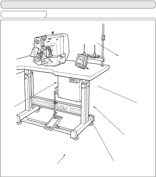
[2] CONFIGURATION
1. Names of main unit
r
w
q Machine head w Work clamp feet e Thread stand r Operation panel t Power switch y Control box
u Pedal switch
2
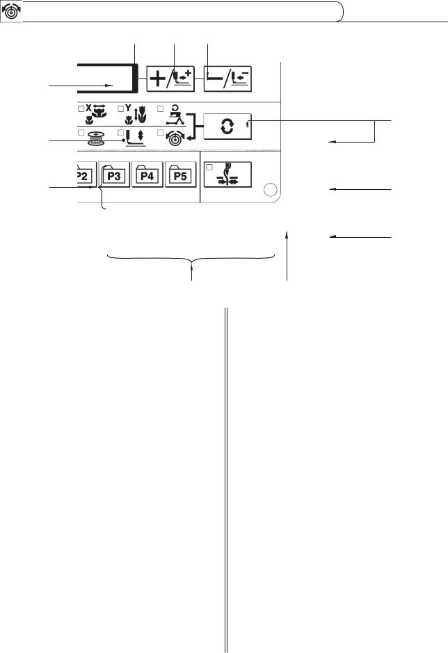
2. Names and explanation of switches on the operation panel
q e r
w
u
i
!1
q“Ready” key
This key changes over the setting state from the panel to the sewing state where the sewing machine actually operates.
wSewing LED
This LED goes off at the time of setting state and lights up at the time of sewing state. Changeover can be performed with “Ready” key.
e“Reset” key
This key is used for canceling error or returning the set value to the initial value.
r“Mode” key
This key makes the setting mode of the memory switch.
t“+/Feed forward” key and “-/Feed backward” key
This key is used for changing pattern No. and X/Y scale, and feed forward/feed backward.
y“Selection” key
This key selects the item to be set. Item selection LED of the selected item and the set value are displayed.
uData indication LED
This LED indicates the set values of the selected items such as pattern No., X/Y scale, etc.
t
y
o
!0
iItem selection LED
LEDs of the selected items light up.
Pattern No. |
X scale |
Y scale |
Max. speed |
Sewing |
Bobbin |
limitation |
counter |
winder |
Work clamp |
Thread |
foot lowering |
tension |
oNeedle thread clamp ON/OFF key
This key selects effective/ineffective of needle thread clamp. When it is effective, needle thread clamp display LED lights up. (Note 1)
!0Needle thread clamp display LED
When this LED lights up, needle thread clamp operates.
!1Needle thread clamp display LED
This key registers the pattern. When this key is pressed, the pattern registered here can sew immediately.
X/Y scale, sewing position, etc. can be changed and registered.
(Note 1) LK-1903A is set to needle thread clamp prohibited (no motion) with memory switch No. 35 at the time of standard delivery.
3

[3] INSTALLATION
1. Installing the electrical box
t |
Install the electrical box on the underside of the table |
|
at the location illustrated using round-head bolt q, plain |
|
washer w, spring washer e and nut r supplied with |
|
the machine, and using bolt having hexagonal |
|
indentation on the head t, spring washer y and plain |
|
washer u supplied with the machine. |
|
|
2. Attaching the connecting rod
1) Fix connecting rod q to installing hole B of pedal lever w with nut e.
2) when connecting rod q is installed in installing hole A, the depressing stroke of the pedal is increased.
w
3. Installing the head support rod
Drive head support rod q in hole w in the machine table.
q
w
4

4.Installing and connecting the power switch
(1)Installing the power switch
|
Fix power switch under the machine table with wood |
|
screws . |
||
|
||
|
Fix the cable with staples supplied with the machine |
|
|
as accessories in accordance with the forms of use. |
|
|
* Five staples including the staple for fixing the |
|
|
operation panel cable are supplied as accessories. |
(2) Connecting the power source cord
Voltage specifications at the time of delivery from the factry are indicated on the voltage indication seal. Connect the cord in accordance with the specifications.
1. Never use under the wrong voltage and phase.
2. When changing the voltage, refer to
Voltage caution seal
the item of "Changing the voltage of 100 / 200V" (P.36).
seal (3-phase type only)
Rating label
• Connecting single phase 200V, 220V, 230V and 240V
Light blue Light blue |
|
|
|
|
|
|
|
|
|
|
|
||
Table |
|
|
|
|
|
|
|
|
|
|
|
AC200 V |
|
|
|
Green/Yellow |
Brown |
|
|
|
|
|
|
||||
|
|
|
|
|
|
|
|
AC220 V |
|||||
|
|
|
|
|
|
|
|
||||||
|
|
|
|
|
|
|
|
|
|
||||
Control box |
|
|
|
Light |
|
|
|
|
|
|
AC230 V |
||
|
|
|
|
|
|
|
|
|
|||||
|
|
|
|
|
|
|
|
|
|
|
AC240 V |
||
|
Plug |
|
blue |
|
|
|
|
|
|
||||
Green/Yellow |
|
|
|
|
|
|
|
|
|||||
|
|
|
|
|
|
|
|
||||||
|
|
|
Green/ |
|
|
GND |
|||||||
|
|
|
|
|
|||||||||
Brown |
Brown |
Power switch |
|
Yellow |
|
||||||||
|
|
|
|
||||||||||
|
|
|
Power source cord |
|
|
|
|
|
|
|
|
|
|
• Connecting three phase 200V, 220V and 240V |
|
|
|
|
|
|
|
|
|
|
|
||
White |
|
White |
|
|
|
|
|
|
|
|
|
|
|
|
|
|
|
White |
|
|
|
|
AC200 V |
||||
|
|
|
|
|
|
|
|
||||||
|
|
|
|
|
|
|
|
|
|
|
|
|
|
Control |
|
|
|
Black |
|
|
|
|
AC220 V |
||||
|
|
|
|
|
|
|
|||||||
|
|
|
|
|
|
|
|
|
|
|
|
AC240 V |
|
|
|
|
|
Red |
|
|
|
|
|
|
|||
|
|
|
|
|
|
|
|
|
|
||||
|
|
|
|
|
|
|
|
|
|
||||
|
|
|
|
Green/ |
|
|
|
GND |
|||||
Black Red |
|
|
|
Yellow |
|
|
|||||||
|
|
|
|
|
|
||||||||
|
|
|
|
|
|
|
|
|
|
|
|
|
|
|
|
Power switch |
Power source cord |
|
|
|
|
|
|
|
|
|
|
5

5. Installation of the sewing machine head
 WARNING :
 To prevent possible accidents caused by the full of the sewing machine, perform the work by two persons
  or more when the machine is moved.
1) Fit hinge rubber q to the hinge shaft ,and fix the sewing machine main unit.
2) When tightening nut e to hinge rubber q, tighten nut e until spring washer w becomes as B in the illustration, and fix it with nut r.
If tightening hinge rubber q excessively, it will not work properly. So, be careful.
Hold section Awhen moving the sewing machine.
|
w |
|
w |
A |
|
|
|
||
|
e |
|
|
|
|
r |
w |
|
|
|
w |
e |
w |
B |
e |
|
r |
||
r |
|
|
||
|
|
|
|
|
|
|
|
|
|
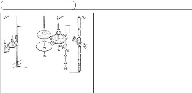
6.Installing the drain receiver and the head support rubber
1)Fix drain receiver w in the installing hole of table q with four setscrews e.
2)Screw in drain bin r to drain receiver w.
3)Insert sewing machine drain pipe t into drain bin r.
4)Insert head support rubber y into table q.
1.Insert drain pipe t until it will go no further so that it does not come off drain bin r when tilting the machine head.
2.Remove the tape fixing drain pipe t.
y
y
6
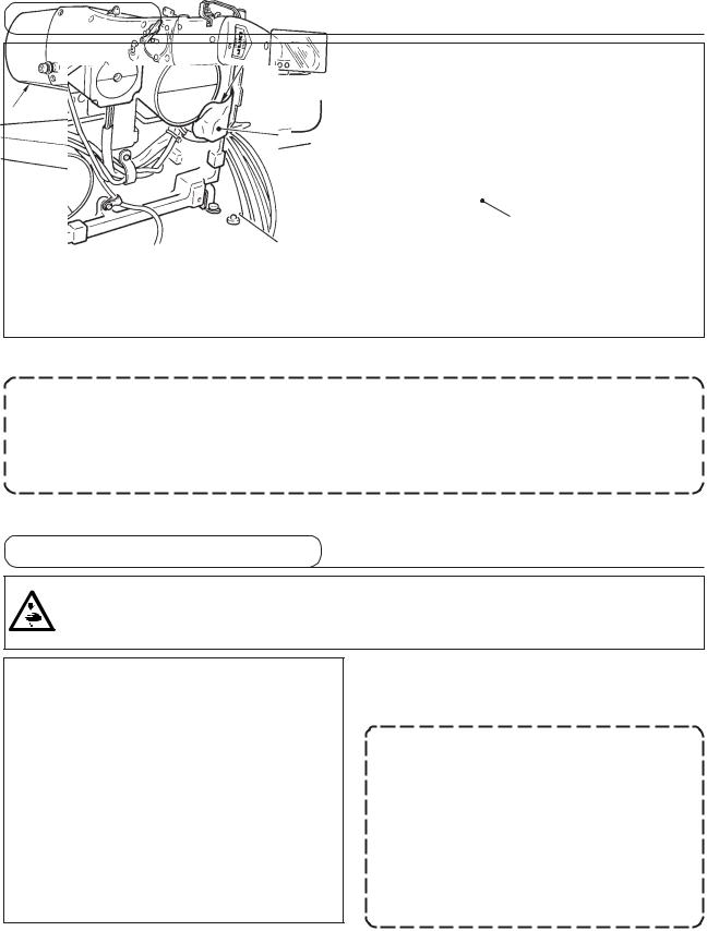
7. Safety switch
w
Remove tape q fixing the lever section of safety switch w.
1.When using the safety switch without removing tape q, it is very dangerous since the sewing machine works even in the state that it is tillted.
Impor tant
2.In case error 302 occurs when the sewing machine works after setup, loosen the safety switch fitting screw with a screwdriver, and lower the switchto the downside of the sewing machine.
8.Tilting the sewing machine head
WARNING :
Tilt/raise the sewing machine head with both hands taking care not to allow your fingers to be caught in the head. Turn OFF the power before starting the work so as to prevent accidents caused by abrupt start of the sewing machine.
When tilting the sewing machine head, tilt the head gently until it comes in contact with head support rod q.
1. Before tilting the sewing machine head, make sure that head support rod qis attached to the machine table.
w q 2. When raising the sewing machine head, do not raise it while holding motor cover w. It will be the cause of breakage of motor cover w.
3. Be sure to tilt the sewing machine head on a flat place to prevent it from falling.
7
9. Installing the operation panel
w q
e
r
Fix operation panel installing plate q on the machine table with wood screws w and pass the cable through hole r in the machine table.
Fix the operation panel on panel installing plate q with screws e supplied as accessories.
Fix the cable on the bottom surface of the table with the staples supplied with the machine as accessories.
Refer to the figure on the left side when installing the panel under the table.
8

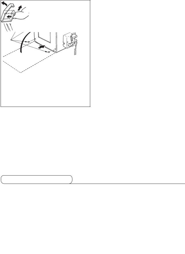
10. Connecting the cord
Remove four screws E fixing the rear cover of the electrical box. When opening the rear cover, pressing it with your hands, slowly open it by approximately 90˚ until it stops as illustrated.
Be sure to lend your hand to the rear cover in order not to let the rear cover fall. In
Slowly
addition, do not apply force to the rear cover opened.
CN16 |
4P |
White |
|
|
White |
|
|||
CN14 |
9P |
Sewing machine head |
||
|
|
|||
CN39 |
2P |
Yellow |
|
|
|
|
|||
CN42 |
6P |
White |
|
|
|
|
|||
CN43 |
6P |
Blue |
|
|
|
|
|||
CN44 |
6P |
Red |
Operation panel |
|
Yellow |
||||
CN45 |
6P |
|
||
|
|
|||
CN40 |
4P |
White |
|
|
|
|
|||
CN47 |
2P |
White |
|
|
|
|
|||
(LK-1901A) |
|
|||
CN38 |
16P |
Gray |
|
|
|
|
|||
CN34 |
26P |
Gray |
|
|
|
|
|||
CN16 White |
|
|
|
|
CN14 White |
|
|
||
Earth cord |
|
|
|
|
CN44 Red |
|
|
|
|
CN34 Gray |
|
|
|
|
CN45 |
CN39 Yellow |
|
||
|
|
|
||
Yellow |
|
|
|
|
CN47 |
|
|
|
|
White |
|
|
|
|
CN40 |
|
|
|
|
White |
|
|
|
|
|
CN43 Blue |
|
||
CN42 White |
|
|
|
|
9 |
|
|
||
w |
1) |
Take care so that the cord is not caught between |
|
|
the rear cover and the electrical box main body, |
|
|
close the rear cover while pressing section A on |
|
|
the lower side of the rear cover, and tighten four |
C |
|
screws q. |
|
2) |
Lower downward the cord located on the side of |
|
|
the control box and cord presser plate C in the push |
B |
|
hole B, press the cord and tighten screws w. |
|
|
q
A
How to lock the cord clamp |
|
How to remove the cord clamp |
|||
|
|||||
|
|
|
q Lightly pressing |
||
|
|
|
w Pull down the clamp. |
||
|
|
|
e The clamp goes up. |
||
|
|
q |
|
|
w |
|
|
|
|
|
|
|
Clamp |
|
|
|
|
|
|
|
|
|
|
q Lightly press the corner of clamp. |
|
|
|
q |
|
(Cord clamp is locked with a click.) |
|
|
|
|
|
|
|
|
|
|
|
|
|
|
|
|
|
11. Installing the motor cover
|
Install motor cover q on the machine main unit with |
q |
screws supplied with the machine as accessories. |
|
|
|
|
10

12. Managing the cord
w
q
Slack
1)In the state that the sewing machine is tilted, connect the cords, and bundle them with clip band q as shown in the figure.
2)Fix the cords with cords setting plate w in the state that the cords slacken as shown in the figure.
When you tilt the sewing machine, make sure that the sewing machine head support bar is placed on the table.
13. Installing the eye protection cover
WARNING :
Be sure to attach this cover to protect the eyes from the disperse of needle breakage.
Be sure to install and use eye protection cover q.
q
11
14. Installing the thread stand
1) |
Assemble the thread stand unit, and insert it in the |
|
hole in the machine table. |
2) |
Tighten locknut q to fix the thread stand. |
3) |
For ceiling wiring, pass the power cord through |
w |
spool rest rod w. |
|
q
12
[4] OPERATION OF THE SEWING MACHINE
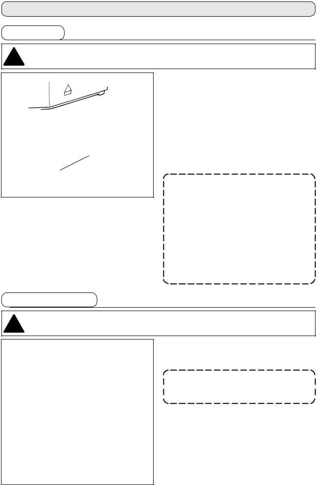
1. Lubrication
 WARNING :
 Turn OFF the power before starting the work so as to prevent accidents caused by abrupt start of the
  sewing machine.
Check that the place between lower line B and upper line A is filled with oil. Fill there with oil using the oiler supplied with the machine as accessories when oil is short.
* The oil tank which is filled with oil is only for lubricating to the hook portion. It is possible to reduce the oil amount when the number of rotation used is low and the oil amount in the hook portion
A  is excessive. (Refer to 8. Amount of oil supplied to
the hook of [7] MAINTENANCE.)
B
1. Do not lubricate to the places other than the oil tank and the hook of C a u t i o n 2 b e l o w . T r o u b l e o f components will be caused.
2. When using the sewing machine for the first time or after an extended period of disuse, use the machine after lubricating a small amount of oil to the hook portion. (Refer to 2. Adjusting the needle-to-shuttle relation of [7] MAINTENANCE.)
2. Attaching the needle
 WARNING :
 Turn OFF the power before starting the work so as to prevent accidents caused by abrupt start of the
  sewing machine.
Loosen setscrew and hold needle with the long groove facing toward you. Then fully insert it into the hole in the needle bar, and tighten setscrew .
If the stitches are made as shown in , attach the needle facing to the directionto a small extent.
13

3. Threading the machine head
 WARNING :
 Turn OFF the power before starting the work so as to prevent accidents caused by abrupt start of the
  sewing machine.
q
w
Thin synthetic thread or the like
Pull out the thread by approximately 4 cm from the needle after threading through the needle.
1.When the silicon oil is used, thread through thread guide for silicon q (Optional)
2.For thick thread, pass the thread through one hole only of needle bar thread guide w.
4.Installing and removing the bobbin case
 WARNING :
 Turn OFF the power before starting the work so as to prevent accidents caused by abrupt start of the
  sewing machine.
1) Open hook cover q.
e2) Raise latch e of bobbin case w, and remove the bobbin case.
3)When installing the bobbin case, fully insert it into the shuttle shaft, and close the latch.
w |
If it is not fully inserted, bobbin case w |
q |
may slip off during sewing. |
|
14

5. Installing the bobbin
 WARNING :
 Turn OFF the power before starting the work so as to prevent accidents caused by abrupt start of the
  sewing machine.
|
|
1) Set the bobbin qinto bobbin case win the direction |
|
2.5 cm |
|
shown in the figure. |
|
r |
|
2) |
Pass the thread through thread slit e of bobbin |
|
t |
|
case w, and pull the thread as it is. By so doing, |
|
|
|
|
|
|
|
the thread will pass under the tension spring and |
|
|
|
be pulled out from thread hole r. |
|
|
3) |
Pass the thread through thread hole t of the horn |
|
|
|
section, and pull out the thread by 2.5 cm from the |
e |
|
|
thread hole. |
|
|
|
|
q |
w |
|
If the bobbin is installed in the bobbin |
|
case orienting the reverse direction, the |
||
|
|
|
|
|
|
|
bobbin thread pulling out will result in an |
|
|
|
inconsistent state. |
6. Adjusting the thread tension
q
Long
w
Short
Adjusting the needle thread tension
h
If thread tension controller No. 1 qis turned clockwise, the length of remaining thread on the needle after thread trimming will be shorter. If it is turned counterclockwise, the length will be longer.
Shorten the length to an extent that the thread is not slipped off.
Adjust needle thread tension from the operation panel and bobbin thread tension with w.
1)Select thread tension  with
with  key.
key.
2)Set needle thread tension with  key or
  key. There is a setting range of 0 to 200. When the
set value is increased, the tension becomes higher.
*The tension is set so that 1.5 N (spun thread #50) is obtained at the set value 50 at the time of standard delivery. (When thread tension No. 1 is released)
15

7. Adjusting the thread take-up spring
|
|
|
|
The standard stroke of thread take-up spring is 8 to |
|
|
|
|
|
10 mm, and the pressure at the start is 0.1 to 0.3N. |
|
|
|
|
|
1) |
Adjusting the stroke |
|
|
|
Loosen setscrew , and turn thread tension asm. |
||
|
|
|
|
|
. |
|
|
|
|
|
Turning it clockwise will increase the moving |
|
|
|
|
|
|
|
|
|
|
|
amount and the thread drawing amount will |
|
|
|
|
|
increase. |
|
|
|
|
2) |
Adjusting the pressure |
|
|
|
|
|
To change the pressure of the thread take-up |
|
|
|
|
||
|
|
|
|
|
|
|
|
|
|
|
spring, insert a thin screwdriver into the slot of |
|
|
|
|
|
thread tension post while screw is tightened, |
|
|
|
|
|
and turn it. Turning it clockwise will increase the |
|
|
|
|
|
|
|
|
|
|
|
pressure of the thread take-up spring. Turning it |
|
|
|
|
|
counterclockwise will decrease the pressure. |
8. Example of the thread tension
When using the sewing machine for the first time, adjust the thread tension referring to the table below.
Thread |
Material |
Needle thread |
Thread take-up spring moving |
|
Strength |
|
|||||
|
|||||
|
|
tension setting |
amount [Thread drawing amount] |
|
|
|
|
|
|
||
|
|
|
|
||
|
|
|
|
||
|
|
|
|
|
|
Polyester filament thread #50 |
Wool |
30 to 35 |
10mm [13mm] |
|
0.1N |
|
|||||
Polyester spun thread #50 |
Wool |
50 to 55 |
10mm [13mm] |
|
0.2N |
|
|||||
|
|
|
|
|
|
Polyester spun thread #60 |
T/C broad |
30 to 35 |
8 to 10mm [11 to 13mm] |
|
0.1N |
(Thread clamp OFF) |
|
|
|
|
|
|
|
|
|
|
|
|
|
|
|
|
|
Cotton thread #50 |
Denim |
35 to 45 |
10mm [13mm] |
|
0.1N |
|
|||||
|
|
|
|
|
|
Cotton thread #20 |
Denim |
35 to 45 |
8 to 10mm [11 to 13mm] |
|
0.1N |
|
16

[5] OPERATION OF THE SEWING MACHINE (BASIC)
1. Item data setting
Set each item following the procedure described below.
Setting of the |
e |
Setting of the |
e |
Setting of the |
e |
Setting of the |
e |
Setting the |
|
speedmax.limitationsewing |
|||||||||
pattern No. |
X scale |
Y scale |
thread tension |
||||||
|
|
|
|
|
|
|
|
|
(1) Turn ON the power switch.
Pattern No. of the item selection lights up, and the pattern No. is indicated on the data display.
(2) Setting of the pattern No.
h
(3) Setting of the X scale
h
(4) Setting of the Y scale
h
1)Press the  key to indicate the item “Pattern NO”
 .
.
2)Press the  or
or  key to indicate “ 14 ”on the display. (Pattern No. is set to 14.)
Refer the pattern No. to the separate table.
1)Press the  key to indicate the item “X Scale”
 .
.
2)Press the  or
or  key to indicate “100”. (Set X scale to 100%.)
The setting exceeding 100% is dangerous since needle and the cloth presser interferes with each other and needle breakage or the like will occur.
1)Press the  key to indicate the item “Y Scale”
 .
.
2)Press the  or
or  key to indicate “100”. (Set Y scale to 100%.)
The setting exceeding 100% is dangerous since needle and the cloth presser interferes with each other and needle breakage or the like will occur.
17
(5)Setting of the max. sewing speed limitation
1)Press the  key to indicate the item “Speed”
 .
.
2)Press  or
or  key to indicate “400”. (Setting of 400 rpm)
h
(6) Setting the thread tension
1) Press  key to indicate the item “THREAD TENSION”
  .
.
2) Press  or
or  key to indicate “50”. (0 to
200 can be set.)
h
(7) Finish of setting
e 
1)Press the  key.
key.
2)After the work clamp feet have moved and gone up, the sewing LED lights up, and the sewing is ready.
When the presser is raised, be careful that fingers are not caught in the presser since the presser moves after having lowered.
* |
When |
key is pressed, the set values of pattern No., X/Y scale, etc. are memorized. |
* |
If |
key is pressed, you can make sure of the respective setting items again. However, the items can |
|
not be changed in the state that the SEWING LED is lit up. |
|
*When  key is pressed, the READY LED goes off. Set values of the respective items can be changed.
*Thread tension can be changed even when the sewing LED lights up. Thread tension can be momorized with the start switch as well.
*Use the machine after confirming the pattern No. When  key is pressed while pattern No. is indicated "0" (state at the time of delivery), error display E-10 appears. At this time, re-set the pattern No.
Impor tant When turning OFF the power without pressing  key, the set values of pattern No., X/Y scale, number of max. rotation, and thread tension are not memorized.
18
2. Checking the contour of a sewing pattern
WARNING :
1. Make sure without fail of the contour of the sewing pattern after selection of the sewing pattern. If
the sewing pattern extends outside the work clamp feet, the needle will interfere with the work clamp feet during sewing, causing dangerous troubles including needle breakage.
2.When making sure of the contour of the sewing pattern, press + / - key with the needle bar lowered, and the work clamp feet move after automatically making the needle bar return to the upper position.
1)Press  key to make the READY LED light up.
2)Select the work clamp foot lowering  with
with 
key.
3) Lower the work clamp feet with the foot switch.
h
The sewing machine does not start even when the foot switch is
Reference
depressed under this mode.
4)Press  key in the state that the work clamp feet are lowered.
d
h
|
The work clamp feet do not go up even |
Reference |
when the foot switch is detached. |
5) Confirm the contour of the pattern with  key or
  key.
key.
6) The work clamp feet will go up when key is pressed.
The work clamp feet do not come down immediately after turning ON the power.

 10mm
10mm
|
|
|
(Caution) |
When using a sewing pattern which is |
|
|
|
|
full in lengthwise direction (+10 mm), |
|
|
|
|
|
|
|
|
Clearance |
make sure of the clearance between |
|
|
|
||
|
|
|
||
|
|
|
|
cloth feed base and wiper base . If |
|
|
|
|
|
|
|
there is no clearance, loosen setscrew |
||
|
Needle |
and move the wiper to the needle |
||
|
side. Especially when the needle |
|||
|
|
|
|
|
|
|
|
|
position comes to the rear on the right |
|
|
|
|
side, the clearance is decreased. |
Clearance
19

3. Sewing
/
/
a
/ /
1)Set a workpiece on the work clamp foot section.
2)Depress the pedal switch to the first step, and the work clamp feet will come down. If you detach your foot from the pedal switch, the work clamp feet will go up.
3)Depress the pedal switch to the second step after descending the work clamp feet at the first step, and the sewing machine will start sewing.
4)After the sewing machine completes sewing, the work clamp feet will go up, and return to the sewing start position.
4. Change to the other sewing pattern
h
1)Make the Sewing LED go off with  key.
key.
2)Press  key and select the item of pattern No
 .
.
3)Set the pattern No. with  key or
  key
key
4)Similarly, setting of X/Y scale, speed, etc. is performed.
5)When  key is pressed, the Sewing LED lights up and the sewing machine is in the sewing ready
state.
h
WARNING :
Make sure without fail of the contour of the sewing pattern after selection of the sewing pattern.
 If the sewing pattern extends outside the work clamp feet, the needle will interfere with the work clamp
  feet during sewing, causing dangerous troubles including needle breakage.
20

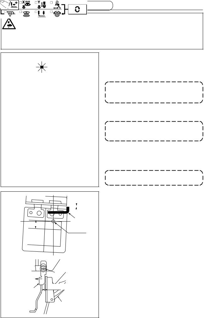
5. Winding a bobbin
5-1. To wind a bobbin while the sewing machine is performing sewing
Thread the bobbin winder and wind the bobbin thread onto the bobbin as illustrated in the figure.
5-2. To wind a bobbin independently
h
h
d
1)Press  key to make the SEWING LED go off.
2)Select the bobbin winder  with
with  key.
key.
Selection cannot be performed when the Sewing LED is lit up.
3)Press  key. The work clamp feet come down and the Sewing LED lights up.
4)When the pedal switch is depressed, the sewing machine rotates.
5)When the pedal is depressed again, or  key or
 key is pressed, the sewing machine stops.
6)When  key is pressed, the Sewing LED goes off, the work clamp feet go up and
  key becomes effective.
Bobbin winder does not work immediately after turning ON the power. Perform the bobbin winding after setting pattern No. or the like once, pressing the  key, and making the sewing LED light up.
h
21
Loading...