


 Loading...
LK-1900BN Series
INSTRUCTION MANUAL
1
CONTENTS
I.EXPLANATION OF THE LK-1900BN, COMPUTER-CONTROLLED HIGH-
SPEED BARTACKING MACHINE......... |
1 |
|
1. SPECIFICATIONS.............................................. |
1 |
|
2. CONFIGURATION.............................................. |
2 |
|
2-1. |
Names of main unit............................................ |
2 |
2-2. |
Names and explanation of switches on the |
|
|
operation panel.................................................. |
3 |
3. INSTALLATION.................................................. |
4 |
|
3-1. |
Installing the electrical box............................... |
4 |
3-2. |
Installing the pedal sensor................................ |
4 |
3-3. Attaching the connecting rod........................... |
5 |
|
3-4. |
Installing the head support rod........................ |
5 |
3-5. |
Installing and connecting the power switch.... |
6 |
3-6. |
How to carry the sewing machine.................... |
7 |
3-7. |
Installation of the sewing machine head......... |
7 |
3-8. |
Installing the drain receiver and the head |
|
|
support rubber................................................... |
8 |
3-9. |
Safety switch...................................................... |
8 |
3-10. Tilting the sewing machine head...................... |
9 |
|
3-11. Installing the operation panel........................... |
9 |
|
3-12. Connecting the cords...................................... |
10 |
|
3-13. Handling the cords.......................................... |
11 |
|
3-14. Installing the eye protection cover................ |
12 |
|
3-15. Installing the thread stand.............................. |
13 |
|
3-16. In the case the machine is transported |
|
|
|
after factory-completed at the time of |
|
|
shipment........................................................... |
13 |
4. OPERATION OF THE SEWING MACHINE..... |
14 |
|
4-1. Lubrication........................................................ |
14 |
|
4-2. Attaching the needle........................................ |
14 |
|
4-3. Threading the machine head.......................... |
15 |
|
4-4. Installing and removing the bobbin case...... |
15 |
|
4-5. Installing the bobbin........................................ |
16 |
|
4-6. Adjusting the thread tension.......................... |
16 |
|
4-7. Adjusting the thread take-up spring.............. |
17 |
|
4-8. Example of the thread tension........................ |
17 |
|
5. OPERATION OF THE SEWING MACHINE |
|
|
(BASIC)............................................................ |
17 |
|
5-1. Selection of language...................................... |
17 |
|
5-2. Setting the pattern number............................. |
18 |
|
5-3. Setting the item data........................................ |
18 |
|
5-4. Checking the contour of a sewing pattern.... |
21 |
|
5-5. Sewing............................................................... |
22 |
|
5-6. Changing the pattern to a different one......... |
22 |
|
5-7. Winding a bobbin............................................. |
23 |
|
5-8. Thread clamp device........................................ |
24 |
|
5-9. LED hand light.................................................. |
26 |
|
6. OPERATION OF THE SEWING MACHINE |
|
|
(ADVANCED).................................................... |
27 |
|
6-1. Performing sewing using the pattern keys ... |
27 |
|
6-2. Sewing using the combination function |
|
|
|
(cycle sewing).................................................. |
32 |
6-3. Sewing through the use of the counter......... |
35 |
|
6-4. How to use the temporary stop...................... |
38 |
|
6-5. Setting the pattern thread tension.................. |
39 |
|
6-6. Copying or deleting various kinds of |
|
|
|
pattern data...................................................... |
40 |
6-7. Communication................................................ |
42 |
|
6-8. Cautions in operation...................................... |
45 |
6-9. Setting enable/disable of standard pattern |
|
invoking............................................................ |
46 |
6-10. Setting the irregular work.............................. |
47 |
7. MAINTENANCE................................................ |
49 |
7-1. Adjusting the height of the needle bar........... |
49 |
7-2. Adjusting the needle-to-shuttle relation........ |
50 |
7-3. Adjusting the lift of the work clamp foot....... |
51 |
7-4. The moving knife and counter knife............... |
51 |
7-5. Needle thread clamp device............................ |
52 |
7-6. Adjustment of the wiper.................................. |
52 |
7-7. Draining waste oil............................................ |
53 |
7-8. Amount of oil supplied to the hook................ |
53 |
7-9. Replacing the fuse........................................... |
53 |
7-10. Replenishing the designated places with |
|
grease............................................................... |
54 |
8. HOW TO USE THE MEMORY SWITCH.......... |
56 |
8-1. Method of changing memory switch data..... |
56 |
8-2. List of the memory switch functions.............. |
57 |
9. OTHERS........................................................... |
61 |
9-1. Table of the standard pattern specifications.61 |
|
9-2. Table of the standard patterns........................ |
62 |
9-3. Table of the work clamp foot........................... |
64 |
9-4. Installing the foot pedal switch (optional)..... |
66 |
9-5. Error list............................................................ |
67 |
9-6. Message list...................................................... |
72 |
9-7. Troubles and corrective measures (sewing |
|
conditions)........................................................ |
74 |
9-8. Table of the optional parts.............................. |
76 |
II.EXPLANATION OF THE LK-1901BN, COMPUTER-CONTROLLED HIGHSPEED EYELET BUTTONHOLE
BARTACKING MACHINE...................... |
78 |
1. SPECIFICATIONS............................................ |
78 |
2.INSTALLATION OF THE SEWING MACHINE AND PREPARATION OF THE
OPERATION..................................................... |
78 |
3.PREPARATION OF THE SEWING MACHINE.79
3-1. Adjustment of the material closing amount.. 79 3-2. Adjustment of the lift of the work clamp foot.79 3-3. Adjustment of the pressure of the work
|
clamp unit......................................................... |
80 |
3-4. |
Setting of the material closing operation...... |
80 |
4. OPERATION OF THE SEWING MACHINE..... |
81 |
|
4-1. |
Selection and confirmation of the sewing |
|
|
patterns............................................................. |
81 |
i
III.EXPLANATION OF THE LK-1902B, COMPUTER-CONTROLLED HIGHSPEED BELT-LOOP ATTACHING
MACHINE............................................. |
82 |
|
1. SPECIFICATIONS............................................ |
82 |
|
2. PREPARATION OF THE SEWING MACHINE.82 |
||
2-1. |
Threading the machine.................................... |
82 |
3. OPERATION OF THE SEWING MACHINE..... |
83 |
|
3-1. |
Selection and confirmation of the sewing |
|
|
patterns............................................................. |
83 |
3-2. |
Combination of the work clamp foot and |
|
|
the feed plate.................................................... |
83 |
IV.EXPLANATION OF THE LK-1903BN, |
|
|
COMPUTER-CONTROLLED HIGH- |
|
|
SPEED LOCKSTITCH BUTTON |
|
|
SEWING MACHINE.............................. |
84 |
|
1. SPECIFICATIONS............................................ |
84 |
|
2.PREPARATION OF THE SEWING MACHINE.84
2-1. Installation of the sewing machine and
|
preparation of the operation........................... |
84 |
2-2. Needle and thread............................................ |
84 |
|
2-3. |
Various sewing modes.................................... |
85 |
3. ADJUSTMENT OF THE SEWING MACHINE..86 |
||
3-1. |
Position of the button clamp jaw lever.......... |
86 |
3-2. Adjusting the feed plate.................................. |
87 |
|
3-3. Adjusting the button clamp jaw lever............ |
88 |
|
3-4. Adjusting the lifting amount of the button |
|
|
|
clamp................................................................. |
88 |
3-5. Adjustment of the pressure of the work |
|
|
|
clamp unit......................................................... |
89 |
3-6. Adjustment of the wiper spring...................... |
89 |
|
4. OTHERS........................................................... |
90 |
|
4-1. |
Installing the save button bar (accessory |
|
|
part)................................................................... |
90 |
4-2. |
Model classification according to the |
|
|
button size........................................................ |
90 |
4-3. Attaching the shank button (optional)........... |
91 |
|
V.EXPLANATION OF THE LK1903BBN HIGH-SPEED COMPUT- ER-CONTROLLED FLAT BUTTON SEWING MACHINE (WITH THE BIRD'S NEST PREVENTING AND SHORTER-THREAD REMAINING
TYPE THREAD TRIMMER).................. |
95 |
1. SPECIFICATIONS............................................ |
95 |
2.PREPARATION OF THE SEWING MACHINE.95
2-1. Installation of the sewing machine and
|
preparation of the operation........................... |
95 |
2-2. Installing the regulator and solenoid valve |
|
|
|
asm.................................................................... |
96 |
2-3. Connecting the air piping................................ |
96 |
|
2-4. Connecting the cords...................................... |
99 |
|
2-5. Installing the air hose.................................... |
100 |
|
2-6. |
Installing the cloth chip bag.......................... |
100 |
2-7. |
Fixing the finger guard.................................. |
100 |
2-8. |
Needle and thread.......................................... |
101 |
2-9. |
Various sewing modes.................................. |
101 |
3.ADJUSTMENT OF THE SEWING MACHINE.102
3-1. Adjusting the knife for the shorter thread
remaining thread trimmer............................. |
102 |
3-2. Adjusting the suction pipe for the shorter- |
|
thread remaining type thread trimmer......... |
103 |
3-3. Replacing the knife of the shorter-thread |
|
remaining type thread trimmer..................... |
104 |
3-4. Adjusting the work clamp rod (For |
|
1903BBNS only)............................................. |
105 |
3-5. Replacing the non-slip sheet (For |
|
1903BBNS only)............................................. |
105 |
4. MAINTENANCE.............................................. |
106 |
4-1. Cleaning the inside of the hook cover......... |
106 |
4-2. Cleaning the thread clamp............................ |
106 |
VI. ............................................................ |
|
EXPLANATION OF THE LK- |
|
1900BBN COMPUTER-CON- |
|
TROLLED, HIGH-SPEED BARTACK- |
|
ING MACHINE (WITH THE BIRD'S |
|
NEST PREVENTING AND SHORT- |
|
ER-THREAD REMAINING TYPE |
|
THREAD TRIMMER)............................. |
107 |
1. SPECIFICATIONS.......................................... |
107 |
2. PREPARATION OF THE SEWING |
|
MACHINE....................................................... |
108 |
2-1. Table of the sewing patterns......................... |
108 |
3.ADJUSTMENT OF THE SEWING MACHINE.110
3-1. Replacing the bird's nest preventing knife.. 110
VII. DRAWING OF THE TABLE............. |
111 |
ii

I.EXPLANATION OF THE LK-1900BN, COMPUTERCONTROLLED HIGH-SPEED BARTACKING MACHINE
1.SPECIFICATIONS
1 |
Sewing area |
X (lateral) direction 40 mm Y (longitudinal) direction 30 mm |
|
|
|
|
|
2 |
Max. sewing speed |
3,200 sti/min* (When sewing pitches are less than 5 mm in X-direction |
|
and 3.5 mm in Y -direction.) |
|||
|
|
||
3 |
Stitch length |
0.1 to 10.0 mm (adjustable in 0.1 mm step) |
|
|
|
|
|
4 |
Feed motion of work clamp foot |
Intermittent feed (2-shaft drive by stepping motor) |
|
|
|
|
|
5 |
Needle bar stroke |
41.2 mm |
|
|
|
|
|
6 |
Needle |
DP × 5, DP × 17 |
|
|
|
|
|
7 |
Lift of work clamp foot |
13 mm (standard) Max. 17 mm |
|
|
|
|
|
8 |
Shuttle |
Standard semi-rotary hook (oil wick lubrication) |
|
|
|
|
|
9 |
Lubricating oil |
New Defrix Oil No. 2 (supplied by oiler) |
|
|
|
|
|
10 |
Data recording |
Memory in MAIN PCB (80 Kbite) |
|
|
|
|
|
11 |
Enlarging / Reducing facility |
20% to 200% (1% step) in X direction and Y direction respectively |
|
|
|
|
|
12 |
Enlarging / Reducing method |
Pattern enlargement / reduction can be done by increasing/decreasing |
|
the stitch length |
|||
|
|
||
13 |
Max. sewing speed limitation |
400 to 3,200 sti/min* (100 sti/min steps) |
|
|
|
|
|
|
|
Standard patterns: 51 |
|
14 |
Pattern selection |
User patterns: 1 - 200 |
|
|
|
Media patterns: 1 - 999 |
|
15 |
Bobbin thread counter |
UP/DOWN type (0 to 9999) |
|
|
|
|
|
16 |
Sewing machine motor |
Servo motor |
|
|
|
|
|
17 |
Dimensions |
W : 1,200 mm L : 660 mm H : 1,100 mm |
|
(Use the standard table and stand.) |
|||
|
|
||
18 |
Mass |
Machine head 42 kg, Control box 5.1 kg |
|
|
|
|
|
19 |
Power consumption |
250 VA (Pattern No. 1, 3,200 sti/min, 2-sec pause time) |
|
|
|
|
|
20 |
Operating temperature range |
5 ˚C to 35 ˚C |
|
|
|
|
|
21 |
Operating humidity range |
35% to 85% (No dew condensation) |
|
|
|
|
|
22 |
Line voltage |
Rated voltage ± 10% 50/60 HZ |
|
|
|
|
|
23 |
Noise |
- Equivalent continuous emission sound pressure level (LpA) at the |
|
|
|
workstation : |
|
|
|
A-weighted value of 82 dB; (Includes KpA = 2.5 dB); according to ISO |
|
|
|
10821- C.6.3 -ISO 11204 GR2 at 3,200 sti/min for the sewing cycle, |
|
|
|
1.0s ON (Pattern : No.1). |
|
|
|
- Sound power level (LWA) ; |
|
|
|
A-weighted value of 89 dB; (Includes KWA = 2.5 dB); according to ISO |
|
|
|
10821- C.6.3 -ISO 3744 GR2 at 3,200 sti/min for the sewing cycle, 1.0s |
|
|
|
ON (Pattern : No.1). |
*Reduce the max. sewing speed in accordance with the sewing conditions. Max. sewing speed of LK-1900BNWS (double capacity hook) is 2,700 sti/min.
1
2. CONFIGURATION
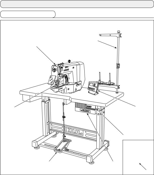
2-1. Names of main unit
|
|
|
|
|
|
|
|
|
|
|
|
Machine headWork clamp feetThread standOperation panelPower switchControl box
Pedal
Power switch (EU type)
2

2-2. Names and explanation of switches on the operation panel
|
|
|
|
|
|
No. |
NAME |
FUNCTION |
|
LCD display |
Various data such as pattern |
|
|
No., shape, etc. are displayed. |
|
READY key |
Press this key when starting |
|
|
sewing. |
|
|
Every time this key is pressed, |
|
|
change-over of sewing ready |
|
|
set state and data set state |
|
|
can be performed. |
|
RESET key |
Press this key when releasing |
|
|
error, traveling the feed mech- |
|
|
anism to its initial position, |
|
|
counter resetting, etc. |
|
MODE key |
This key is used for displaying |
|
|
the mode screen. |
|
|
|
|
PRESSER and |
This key lifts or lowers the |
|
WINDER key |
presser. When the presser |
|
goes up, the needle bar trav- |
|
|
|
|
|
|
els to the origin and when it |
|
|
comes down, the needle bar |
|
|
travels to the right. |
|
|
This key is pressed when |
|
|
performing bobbin winding. |
|
ITEM SELECT key |
This key is used to select the |
|
|
data No. and other kinds of |
|
|
data. |
|
|
|
|
DATA CHANGE key |
This key is used to change the |
|
|
pattern No. and other kinds of |
|
|
data. |
|
|
This key is used to move the |
|
|
feed forward on a stitch-by- |
|
|
stitch basis. |
No. |
NAME |
FUNCTION |
|
EDIT key |
This key is used to display the |
|
|
edit screen, to select the item |
|
|
or to display the detail screen. |
|
|
|
|
RETURN key |
This key is used to return the |
|
|
screen to the previous one. |
|
|
|
|
DIRECT PATTERN |
This key registers the pattern. |
|
|
When this key is pressed, the |
|
|
pattern registered here can |
|
|
sew immediately. |
|
|
X/Y scale, sewing position, |
|
|
etc. can be changed and reg- |
|
|
istered. |
|
THREAD TENSION key |
The thread tension screen is |
|
|
displayed. |
|
|
|
|
THREAD CLAMP |
This key selects effective/ |
|
key |
ineffective of needle thread |
|
|
clamp. When it is effective, |
|
|
needle thread clamp display |
|
|
LED lights up. (Note) |
|
THREAD CLAMP |
When this LED lights up, nee- |
|
LED |
dle thread clamp operates. |
|
SET READY LED |
The LED lights up under the |
|
|
sewing mode. |
|
NFC mark |
Bring the tablet or smartphone |
|
|
close to the NFC mark when |
|
|
carrying out communication. |
|
|
|
(Note ) 1. LK-1903BN is set to needle thread clamp prohibited (no motion) with memory switch U035 at the time of standard delivery.
2.For the LK-1903BBNS, the thread clamp key is disabled.
3
3. INSTALLATION
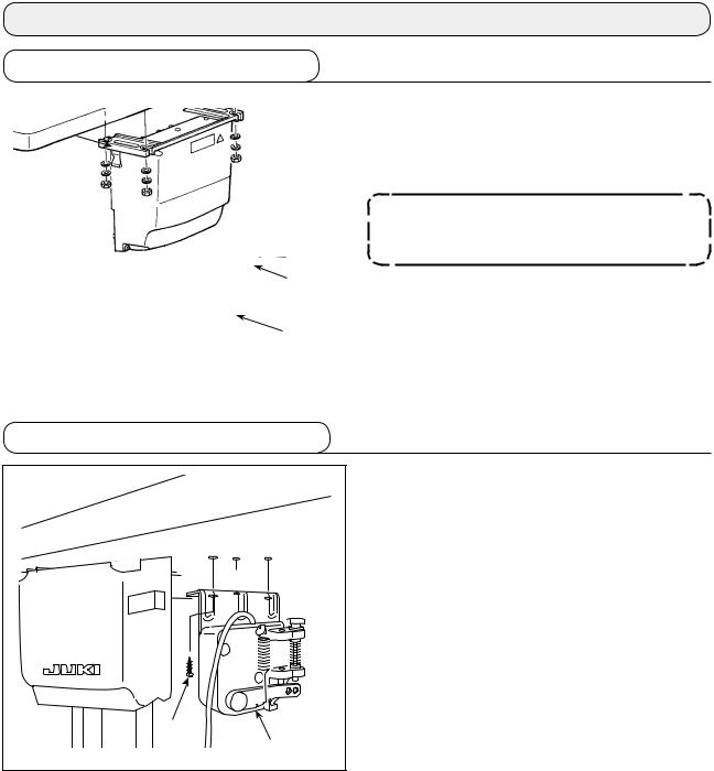
3-1. Installing the electrical box
|
Install control box to the location illustrated in the |
|
|
|
figure using four bolts , four plain washers and |
|
four spring washers and four hexagonal nuts |
|
supplied with the unit. |
|
Bolt is a cup head square neck bolt (M8; |
|
Length: 70 mm) and nut is a hexagonal |
|
nut (M8). |
|
|
3-2. Installing the pedal sensor
|
|
Install the pedal sensor to the table with mounting screws supplied with the unit.
4
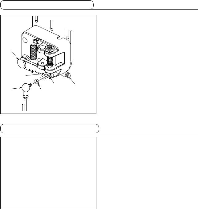
3-3. Attaching the connecting rod
1) Fix connecting rod to installing hole B of pedal lever with nut .
2) The pedal depressing stroke is decreased by fitting connecting rod in mounting hole A.
|
A |
|
|
B |
|
|
|
|
|
|
3-4. Installing the head support rod
Drive head support rod in hole in the machine table.
5
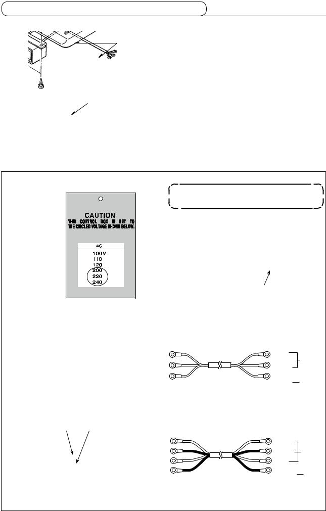
3-5. Installing and connecting the power switch
|
(1) Installing the power switch |
|
|
||
|
Fix power switch |
under the machine table with |
wood screws . |
|
|
|
|
|
|
Fix the cable with staples supplied with the ma- |
|
|
chine as accessories in accordance with the forms of |
|
|
use. |
|
|
|
|
|
|
|
|
|
|
(2) Connecting the power source cord
Voltage specifications at the time of delivery from the factry are indicated on the voltage indication seal. Connect the cord in accordance with the specifications.
Power indication tag
(For example: In the case of 200V)
• Connecting single phase 200V, 220V, 230V and 240V
Never use under the wrong voltage and phase.
Rating plate
|
Brown |
Brown |
|
|
|
|
|
Light |
AC |
|
|
|
blue |
200 V |
Control |
|
|
Brown |
-240 V |
|
|
Power source cord |
Green/ |
GND |
|
|
Yellow |
||
Light blue |
Light blue Power switch |
|
|
|
• Connecting three phase 200V, 220V, 230V and 240V |
|
|
||
White |
Black |
White |
|
|
|
|
|
White |
AC |
|
|
|
|
|
|
|
|
Black |
200 V |
Control |
|
|
Red |
-240 V |
|
|
|
||
Green/Yellow |
|
|
Green/ |
GND |
|
Power source cord |
Yellow |
||
|
|
|||
|
|
|
|
|
Power switch
6
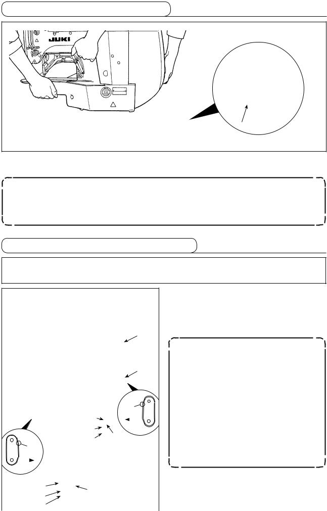
3-6. How to carry the sewing machine
A
To carry the sewing machine, it is necessary to hold A section and support the side faces of the sewing machine by hand as illustrated in the figure.
1.Carefully prevent slippage of your hand that holds the cover.
2.The sewing machine weighs over 42 kg. Be sure to carry the sewing machine with two or more people without exceptions.
3.The LED light is installed to the undersurface of the frame. Do not hold the LED light when moving the frame.
3-7. Installation of the sewing machine head
WARNING :
To prevent possible accidents caused by the full of the sewing machine, perform the work by two persons or more when the machine is moved.
1) Fit hinge rubber cushion over the hinge shaft. 2) Install the main body of the sewing machine on
the table with four bolts , four plain washers , four spring washers , four hexagonal nuts
and four hexagonal nuts .
|
|
|
|
|
|
|
A |
|
|
|
|
|
1. Tighten nut until spring washer |
|
|
|
|
|
|
|
|
|
|
|
|
is brought to the state as illustrated |
|
|
|
|
|
|
|
|
|
|
|
|
in Fig. B and fix the spring washer on |
||
|
|
|
|
|
|
|
|
|
|
hinge rubber with nut . |
|||
|
|
|
|
|
|
|
|
|
|
|
|
|
|
|
|
|
|
|
|
|
|
|
|
|
|
|
2. Mount hinge rubber while orient- |
|
A |
|
|
|
|
|
|
|
|
ing its corner section C toward the |
|||
|
|
|
|
|
|
|
C |
|
machine head side. Be aware that the |
||||
|
|
|
|
|
|
|
|
|
|||||
|
|
|
|
|
|
|
|
|
hinge rubber fails to function properly |
||||
|
|
|
|
|
|
|
|
|
|
|
|
|
|
|
|
|
|
|
|
|
|
|
|
|
|
if nuts and are excessively tight- |
|
|
|
|
|
|
|
|
|
|
|
|
|
|
|
|
|
|
|
|
|
|
|
Machine |
|
|
|||
|
|
|
|
|
|
|
|
|
ened. |
||||
|
|
|
|
|
|
|
head side |
|
|
||||
|
|
C |
|
|
|
|
|
|
|
3. When carrying the sewing machine, |
|||
|
|
|
|
|
|
|
|
|
|
||||
|
|
|
|
|
|
|
|
|
|
hold sections A with hands to support |
|||
|
|
|
|
|
|
|
|
|
|
|
|
|
|
|
|
|
|
|
|
|
|
|
|
|
|
|
the side faces of the sewing machine. |
|
|
|
|
|
|
|
|
|
|
|
|
||
|
Machine |
|
|
|
|
A |
|||||||
|
|
|
|
|
|
|
|||||||
|
head side |
|
|
|
|
|
|
||||||
|
|
|
|
|
|
|
|
|
|
|
|
|
|
|
|
|
|
|
|
B |
|
|
|||||
|
|
|
|
|
|
|
|
||||||
|
|
|
|
|
|
|
|
|
|
|
|
|
|
|
|
|
|
|
|
|
|
|
|
|
|
|
|
|
|
|
|
|
|
|
|
|
|
|
|
7 |
|
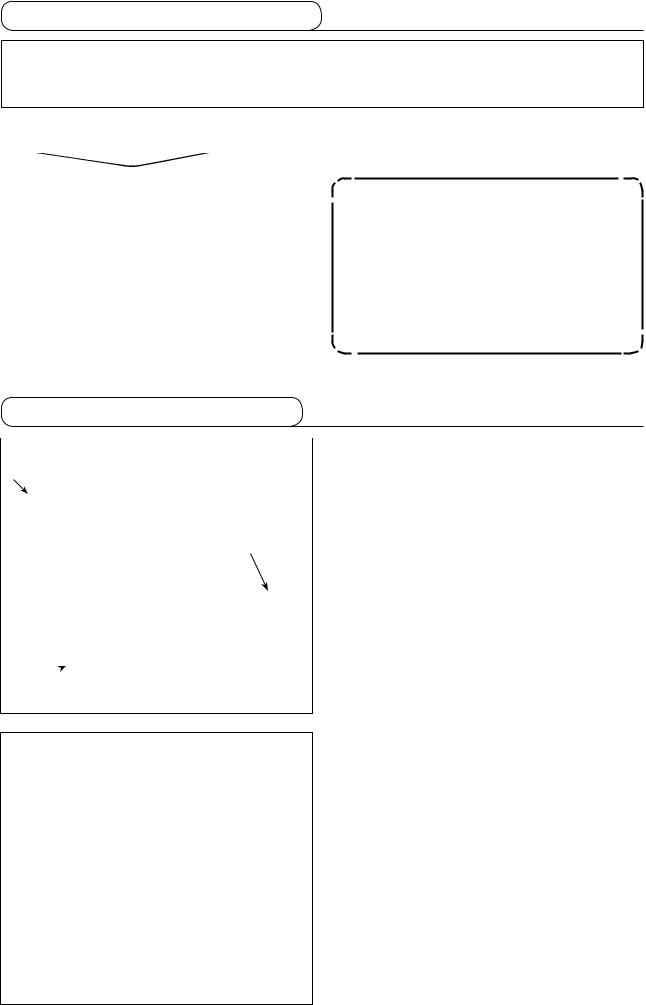
3-8. Installing the drain receiver and the head support rubber
1) Fix drain receiver in the installing hole of tablewith two setscrews .
2) Screw poly-oiler in waste oil reservoir .
3) Insert sewing-machine waste oil pipe into po- ly-oiler .
4) Insert head support rubber into table .
5) Pass bundle of cords through slotted hole
|
in the table. |
|
|
1. Insert drain pipe until it will go no fur- |
|
|
ther so that it does not come off drain |
|
bin when tilting the machine head. |
||
|
2. Remove the tape fixing drain pipe .
3-9. Safety switch
DANGER:
When using the safety switch without removing tape , it is very dangerous since the sewing machine works even in the state that it is tilted.
Remove tape fixing the lever section of safety switch .
In case error 302 occurs when the sewing machine works after setup, loosen the safety switch fitting screw with a screwdriver, and lower the switch to the downside of the sewing machine.
8
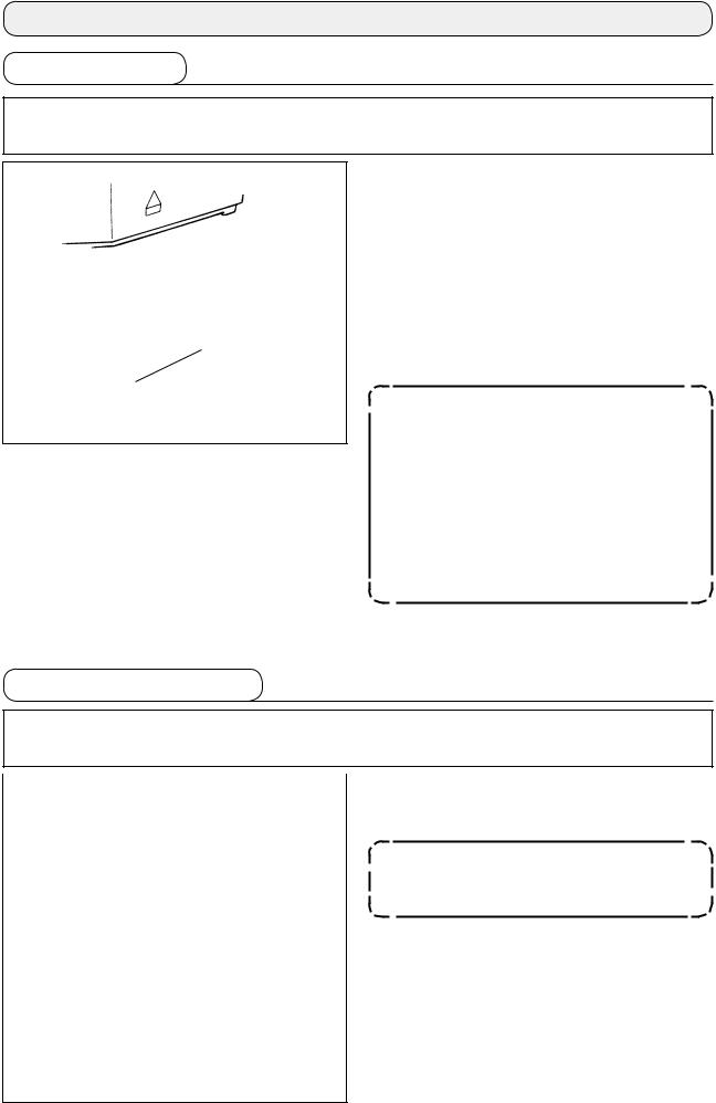
3-10. Tilting the sewing machine head
WARNING :
Tilt/raise the sewing machine head with both hands taking care not to allow your fingers to be caught in the head. Turn OFF the power before starting the work so as to prevent accidents caused by abrupt start of the sewing machine.
|
|
When tilting the sewing machine head, tilt the head |
|
|
|
||
|
|
gently until it comes in contact with head support rod |
|
|
|
. |
|
|
|
1. |
Before tilting the sewing machine head, |
|
|
|
make sure that head support rod is |
|
|
|
attached to the machine table. |
|
|
2. |
When raising the sewing machine |
|
|
head, do not raise it while holding |
|
|
|
|
|
|
|
|
motor cover . It will be the cause of |
|
|
|
breakage of motor cover . |
|
|
3. |
Be sure to tilt the sewing machine head |
|
|
|
on a flat place to prevent it from falling. |
|
|
|
|
3-11. Installing the operation panel
|
|
Fix operation panel mounting plate on the table |
|
|
|
|
|
with four wood screws . Then, pass the cable |
|
through hole in the table. |
|
|
|
|
|
|
|

In the case of installing the operation panel on the undersurface of the table, install the operation panel on panel mounting plate by tightening screws in four mounting holes. Then, fix the panel mounting plate at a desired position on the undersurface of the table with four wood screws .
9

3-12. Connecting the cords
DANGER :
To prevent personal injuries caused by electric shock hazards or abrupt start of the sewing machine, carry out the work after turning OFF the power switch and a lapse of 5 minutes or more. To prevent accidents caused by unaccustomed work or electric shock, request the electric expert or engineer of our dealers when adjusting the electrical components.
1) Loosen four setscrews of control box cover . Remove control box cover .
2) Connect the cords to the respective connectors on MAIN PWB, SDC PWB. (Fig. 1)
3) Fix the ground wire on position A of the control box with a screw. (Fig. 2)
|
|
CN17 |
4P White |
Sewing |
|
|
|
SDC PWB |
9P White |
machine head |
|
|
|
CN15 |
|||
|
|
|
|||
|
|
CN39 |
2P |
White |
|
|
|
CN42 |
6P |
White |
|
|
|
MAIN PWB CN43 |
6P |
Blue |
|
|
|
CN44 |
4P |
Black |
|
|
|
CN45 |
4P |
Red |
|
|
|
CN47 |
2P |
White |
|
|
|
(LK-1901BN) |
|
||
|
|
CN30 |
30P Gray |
Operation panel |
|
|
|
CN34 |
26P Gray |
||
|
|
|
|||
|
|
CN40 |
3P |
White |
Pedal sensor |
|
|
|
|||
CN47 White CN39 |
CN45 |
CN44 Black |
|
|
|
White |
Red |
|
|
|
|
CN43 Blue CN42 White |
|
MAIN PWB |
|
||
|
|
|
|
|
|
CN40 White
CN30 Gray

 A
A
SDC PWB
Shielded ground wire
CN34 Gray |
CN17 White CN15 White |
(Fig. 1) |
(Fig. 2) |
10

3-13. Handling the cords
DANGER :
To prevent personal injuries caused by electric shock hazards or abrupt start of the sewing machine, carry out the work after turning OFF the power switch and a lapse of 5 minutes or more. To prevent accidents caused by unaccustomed work or electric shock, request the electric expert or engineer of our dealers when adjusting the electrical components.


1)Bring the cords under the table into the control box.
2)Put the cord brought into the control box through
cord exit plate and fix cable clip band .
Arrange the cord so that it is not tensed or hitched even when the machine head is  tilted. (See A section)
A
3) Install control box lid with four setscrews .
11

3-14. Installing the eye protection cover
WARNING :
Be sure to attach this cover to protect the eyes from the disperse of needle breakage.
Be sure to use eye protection cover after installing it on installing section with screws .


Pass LED cord through accessory cord clamp supplied with the unit as shown in the figure. Fix the
LED cord with screw located at the lower section of eye protection cover .
12

3-15. Installing the thread stand
1) |
Assemble the thread stand unit, and insert it in |
|
the hole in the machine table. |
2) |
Tighten locknut to fix the thread stand. |
3) |
For ceiling wiring, pass the power cord through |
|
spool rest rod . |
3-16. In the case the machine is transported after factory-completed at the time of shipment


Pass bed fixing bolt , plain washer and nut through hole in the table and hole in the sewing machine bed to fix the bed on the table.
13
4. OPERATION OF THE SEWING MACHINE
4-1. Lubrication
WARNING :
Turn OFF the power before starting the work so as to prevent accidents caused by abrupt start of the sewing machine.
Check that the place between lower line B and upper line A is filled with oil. Fill there with oil using the oiler supplied with the machine as accessories when oil is short.
* The oil tank which is filled with oil is only for lubricating to the hook portion. It is possible to reduce the oil amount when the number of rotation used is low and the oil amount in the hook portion is
A  excessive. (Refer to "I.7-8. Amount of oil sup-
plied to the hook" p.53.)
B
1. Do not lubricate to the places other than the oil tank and the hook of Caution 2 below. Trouble of components will be caused.
2. When using the sewing machine for the first time or after an extended period of disuse, use the machine after lubricating a small amount of oil to the hook portion. (Refer to "I.7-2. Adjusting the needle-to-shuttle relation" p.50.)
4-2. Attaching the needle
WARNING :
Turn OFF the power before starting the work so as to prevent accidents caused by abrupt start of the sewing machine.
|
Loosen setscrew and hold needle with the long |
|
|
|
groove facing toward you. Then fully insert it into |
|
the hole in the needle bar, and tighten setscrew . |
|
If the stitches are made as shown in A, |
|
attach the needle facing to the direction B |
|
to a small extent. |
BA
14

4-3. Threading the machine head
WARNING :
Turn OFF the power before starting the work so as to prevent accidents caused by abrupt start of the sewing machine.

Thin filament thread or the like
1903BBNS sewing machine with the bird's nest preventing and shorter-thread remaining type thread trimmer (Polyester spun thread #80)
Pull out the thread by approximately 40 mm from the needle after threading through the needle.
1.When the silicon oil is used, thread through thread guide for silicon (Optional).
2.For thick thread, pass the thread through one hole only of needle bar thread guide .
4-4. Installing and removing the bobbin case
WARNING :
Turn OFF the power before starting the work so as to prevent accidents caused by abrupt start of the sewing machine.
1) Open hook cover .
2) Raise latch of bobbin case , and remove the bobbin case.
3)When installing the bobbin case, fully insert it into the shuttle shaft, and close the latch.
|
If it is not fully inserted, bobbin case |
|
may slip off during sewing. |
|
15
4-5. Installing the bobbin
WARNING :
Turn OFF the power before starting the work so as to prevent accidents caused by abrupt start of the sewing machine.
|
1) Set the bobbin into bobbin case in the di- |
|
25mm |
||
rection shown in the figure. |
||
|
2) Pass the thread through thread slit of bobbin |
|
|
case , and pull the thread as it is. By so doing, |
|
|
the thread will pass under the tension spring and |
|
|
be pulled out from thread hole . |
|
|
3) Pass the thread through thread hole of the |
|
|
horn section, and pull out the thread by 25mm |
|
|
from the thread hole. |
|
If the bobbin is installed in the bobbin |
||
|
||
case orienting the reverse direction, the |
||
|
||
|
bobbin thread pulling out will result in an |
|
|
inconsistent state. |
4-6. Adjusting the thread tension
|
|
|
If thread tension controller No. 1 is turned clock- |
|
|
|
|
|
|
||
|
|
wise, the length of remaining thread on the needle |
|
|
|
|
|
|
|
|
after thread trimming will be shorter. If it is turned |
|
Long |
|
counterclockwise, the length will be longer. |
|
|
Shorten the length to an extent that the thread is not |
|
|
|
||
|
|
slipped off. |
|
Short |
|
|
|
|
|
|
|
|
|
|
Adjust needle thread tension from the operation pan- |
|
|
|
el and bobbin thread tension with . |
|
|
|
|
|
|
|
|
Adjusting the needle thread tension
1) Press THREAD TENSION key to dis-
play the thread tension input screen.
2) Set a needle thread tension with DATA CHANGE
key  The setting range is 0 to 200. Increasing the value increases the thread tension.
* The sewing machine with standard specifications has been factory-set at 50 (the tension: 1.5 N when using spun thread #50) at the time of ship-
ment. (When the thread tension No. 1 is opened.)
16

4-7. Adjusting the thread take-up spring
|
|
|
|
The standard stroke of thread take-up spring is 8 |
|
|
|
|
|
||
|
|
|
|
to 10 mm, and the pressure at the start is 0.1 to 0.3N. |
|
|
|
|
|
1) |
Adjusting the stroke |
|
|
|
Loosen setscrew , and turn thread tension |
||
|
|
|
|
|
asm. . |
|
|
|
|
|
Turning it clockwise will increase the moving |
|
|
|
|
amount and the thread drawing amount will in- |
|
|
|
|
|
|
|
|
|
|
|
|
crease. |
|
|
|
|
2) |
Adjusting the pressure |
|
|
|
|
|
To change the pressure of the thread take-up |
|
|
|
|
|
|
|
|
|
|
spring, insert a thin screwdriver into the slot of |
|
|
|
|
|
||
|
|
|
|
|
thread tension post while screw is tightened, |
|
|
|
|
|
and turn it. Turning it clockwise will increase the |
|
|
|
|
|
pressure of the thread take-up spring. Turning it |
|
|
|
|
|
|
|
|
|
|
|
counterclockwise will decrease the pressure. |
4-8. Example of the thread tension
When using the sewing machine for the first time, adjust the thread tension referring to the table below.
Thread |
Material |
Needle thread tension |
Thread take-up spring moving |
Strength |
|
|
setting |
amount [Thread drawing amount] |
|
Polyester filament thread #50 |
Wool |
30 to 35 |
10mm [13mm] |
0.1N |
Polyester spun thread #50 |
Wool |
50 to 55 |
10mm [13mm] |
0.2N |
Polyester spun thread #60 |
T/C broad |
30 to 35 |
8 to 10mm [11 to 13mm] |
0.1N |
(Thread clamp OFF) |
|
|
|
|
|
|
|
|
|
Cotton thread #50 |
Denim |
35 to 45 |
10mm [13mm] |
0.1N |
Cotton thread #20 |
Denim |
35 to 45 |
8 to 10mm [11 to 13mm] |
0.1N |
5. OPERATION OF THE SEWING MACHINE (BASIC)
Set each item following the procedure described below.
5-1. Selection of language
When you turn ON the power to the sewing machine for the first time after the purchase, the language
selection screen is displayed. Select the language to be displayed, then press RETURN key  .
.
The language to be displayed on the screen can be changed by means of the memory switch U239 "Language selection". Refer to "I.8. HOW TO USE THE MEMORY SWITCH" p.56 for the details of the memory switch.
If you terminate the language selection by pressing RETURN key  without se-
lecting the language, the language selection screen will be displayed every time you turn ON the power to the sewing machine.
17
5-2. Setting the pattern number
Turn ON the power switch.
Pattern number is displayed on the upper left section
of the screen to indicate the pattern shape, X/Y enlargement/reduction ratios, thread tension value and
sewing speed.
When you press DATA CHANGE key  , the pattern number can be changed.
 Refer the pattern No. to the separate table.
5-3. Setting the item data
When you press EDIT key  , the item data input screen is displayed.
The items that can be edited are displayed on the left section of the screen and the set contents are displayed on the right section of the screen.
Select an item with ITEM SELECT key . Then, change the set content with DATA CHANGE key
 .
.
(1) Inputting the X size
Press ITEM SELECT key |
to display the |
C001 X size. |
|
Press DATA CHANGE key |
to display the |
value you desire. |
|
One of the input method for the X/Y sizes can be selected; i.e., by inputting a percentage (%) with memory switch U064 or by inputting an actual value. (Initial value: Input in terms of percentage (%))
The setting exceeding 100% is dangerous since needle and the cloth presser interferes with each other and needle breakage or the like will occur.
18

(2) Inputting the Y size
Press ITEM SELECT key |
to display the |
C002 Y size. |
|
Press DATA CHANGE key value you desire.
One of the input methods for the X/Y sizes can be selected; i.e., by inputting a percentage (%) with memory switch U064 or by inputting an actual value. (Initial value: Input in terms of percentage (%))
The setting exceeding 100% is dangerous since needle and the cloth presser interferes with each other and needle breakage or the like will occur.
(3) Inputting the sewing speed
Press ITEM SELECT key |
to display the |
C004 sewing speed. |
|
Press DATA CHANGE key value you desire.
The maximum input range is the maximum sewing speed of the memory switch U001.
(4) Setting the comment
Press ITEM SELECT key |
to display the |
C005 comment.
Press EDIT key  to display the comment input screen.
19

|
|
|
|
On the comment input screen, as many as 14 char- |
||||||||||||||||
|
|
|
|
|
|
|||||||||||||||
|
|
|
|
|
|
|
|
|
|
|
|
|
|
|
|
|
acters can be input. The characters that can be input |
|||
|
|
|
|
|
|
|
|
|
|
|
|
|
|
|
|
|
are alphabets, numbers and symbols. |
|
||
|
|
|
|
|
|
|
|
|
|
|
|
|
|
|
|
|
Press ITEM SELECT key |
to specify the |
|
|
|
|
|
|
|
|
|
|
|
|
|
|
|
|
|
|
|
||||
|
|
|
|
|
|
|
|
|
|
|
|
|
|
|
|
|
||||
|
|
|
|
|
|
|
|
|
|
|
|
|
|
|
|
|
||||
|
|
|
|
|
|
|
|
|
|
|
|
|
|
|
|
|
input position. Press DATA CHANGE key |
|||
|
|
|
|
|
|
|
|
|
|
|
|
|
|
|
|
|
to select the characters to be entered. |
|
||
|
|
|
|
|
|
|
|
|
|
|
|
|
|
|
|
|
When you press RESET key |
, the charac- |
||
|
|
|
|
|
|
|
|
|
|
|
|
|
|
|
|
|
||||
|
|
|
|
|
|
|
|
|
|
|
|
|
|
|
|
|
||||
|
|
|
|
|
|
|
|
|
|
|
|
|
|
|
|
|
||||
|
|
|
|
|
|
|
|
|
|
|
|
|
|
|
|
|
ter at the current input position is erased. When you |
|||
|
|
|
|
|
|
|
|
|
|
|
|
|
|
|
|
|
||||
|
|
|
|
|
|
|
|
|
|
|
|
|
|
|
|
|
||||
|
|
|
|
|
|
|
|
|
|
|
|
|
|
|
|
|
keep RESET key |
held pressed, all charac- |
||
|
|
|
|
|
|
|
|
|
|
|
|
|
|
|
|
|
||||
|
|
|
|
|
|
|
|
|
|
|
|
|
|
|
|
|
||||
|
|
|
|
|
|
|
|
|
|
|
|
|
|
|
|
|
ters which have been input are erased. |
|
||
|
|
|
||||||||||||||||||
|
|
|
|
|
||||||||||||||||
After the completion of input of a comment, the screen is returned to the previous screen by pressing RETURN key  .
.
(5) Setting the thread tension
Press THREAD TENSION key  to display
the C003 thread tension.
Press DATA CHANGE key  to display the
value you desire. (Input range: 0 - 200)
After setting the sewing data, press RETURN key  to return to the input screen.
(6) Completing the setting
Press READY key  .
.
The work clamp moves. Then, SET READY LED
lights up after the work clamp has gone up to enable
sewing.
When the presser is raised, be careful that fingers are not caught in the presser since  the presser moves after having lowered.
*When READY key  is pressed, the set values of pattern No., X/Y scale, etc. are memorized.
*When READY key  is pressed, SET READY LED goes out. Setting of each item can be changed.
*The thread tension can be changed even when the SET READY LED lights up. The thread tension is stored in memory with the start switch.
*Check the pattern number before use. If you press READY key  with pattern number 0 displayed, error display E010 will be shown on the screen. At this time, re-set the pattern number.
When turning OFF the power without pressing READY key , the set values of pattern
No., X/Y scale, number of max. rotation, and thread tension are not memorized.
20

5-4. Checking the contour of a sewing pattern
WARNING :
1.Make sure without fail of the contour of the sewing pattern after selection of the sewing pattern. If the sewing pattern extends outside the work clamp feet, the needle will interfere with the work clamp feet during sewing, causing dangerous troubles including needle breakage.
2.When making sure of the contour of the sewing pattern, press + / - key with the needle bar lowered, and the work clamp feet move after automatically making the needle bar return to the upper position.
|
|
|
|
|
|
|
|
|
|
|
|
|
to light up the SET |
|||||||||
|
|
|
|
|
|
|
|
|
|
|
|
1) |
Press READY key |
|||||||||
|
|
|
|
|
|
|
|
|
|
|
|
|
|
|
|
|
|
|
|
READY LED . |
|
|
|
|
|
|
|
|
|
|
|
|
|
|
|
|
|
|
|
|
|
|
|||
|
|
|
|
|
|
|
|
|
|
|
|
|
2) |
Press work PRESSER and WINDER key |
||||||||
|
|
|
|
|
||||||||||||||||||
|
|
|
|
|
|
|
|
|
|
|
|
|
|
|
|
|
|
|
|
to display "work clamp lowering screen". |
||
|
|
|
3) |
Display the shape check screen with + key |
||||||||||||||||||
|
|
|
|
|
|
|
|
|
|
|
|
|
|
|
|
|
|
|
|
. |
|
|
|
|
|
|
|
|
|
|
|
|
|
|
|
|
|
|
|
|
|
|
Under this mode, the sewing machine will |
||
|
|
|
|
|
|
|
|
|
|
|
|
|
|
|
|
|
|
|
|
|||
|
|
|
|
|
|
|
|
|
|
|
|
|
|
|
|
|
|
|
|
|||
|
|
|
|
|
|
|
|
|
|
|
|
|
|
|
|
|
|
|
|
|||
|
|
|
|
|
|
|
|
|
|
|
|
|
|
|
|
|
|
|
|
not start running even if you depress the |
||
|
|
|
|
|
|
|
|
|
|
|
|
|
|
|
|
|
|
|
|
|||
|
|
|
|
pedal. |
|
|
||||||||||||||||
|
|
|
|
|
||||||||||||||||||
|
|
|
|
|
|
|
|
|
|
|
|
|
|
|
||||||||
|
|
|
|
|
4) |
Check the shape with DATA CHANGE key |
||||||||||||||||
|
|
|
|
|
|
|
|
|
|
|
|
|
|
|
|
|
|
|
|
. |
|
|
|
|
|
|
|
|
|
|
|
|
|
|
|
|
|
|
|
|
|
|
|
|
|
|
|
|
|
|
|
|
|
|
|
|
|
|
5) |
Press RESET key |
to return to the |
|||||||
|
|
|
|
|
|
|
|
|||||||||||||||
|
|
|
|
|
|
|
|
|
|
|
|
|
|
|||||||||
|
|
|
|
|
|
|
|
|
|
|
|
|
|
|
|
|
|
|
|
sewing starting position and lift the work clamp. |
||
|
|
|
|
|
|
|
|
|
|
|
|
|
|
|
|
|
|
|
|
When you press RETURN key |
, the |
|
|
|
|
|
|
|
|
|
|
|
|
|
|
|
|
|
|
|
|
|
sewing screen is displayed at the current posi- |
||
|
|
|
|
|
|
|
|
|
|
|
|
|
|
|
|
|
|
|
|
tion. |
|
|
|
|
|
|
|
|
|
|
|
|
|
|
|
|
|
|
|
|
|
|
|
|
|
|
|
|
|
|
|
|
|
|
|
|
|
|
|
|
|
|
|
|
|
|
|
|
|
|
|
|
|
|
|
|
|
|
|
|
|
|
|
|
|
|
|
|
When you depress the pedal in the aforemen- |
||
|
|
|
|
|
|
|
|
|
|
|
|
|
|
|
|
|
|
|
|
|||
|
|
|
|
|
|
|
|
|
|
|
|
|
|
|
|
|
|
|
|
|||
|
|
|
|
|
|
|
|
|
|
|
|
|
|
|
|
|
|
|
|
tioned state, the sewing machine starts sewing |
||
|
|
|
|
|
|
|
|
|
|
|
|
|
|
|
|
|
|
|
|
|||
|
|
|
|
|
|
|
|
|
|
|
|
|
|
|
|
|
|
|
|
from the current position. |
|
|
|
|
|
|
|
|
|
||||||||||||||||
10mm
Clearance |
|
|
|
|
|
|
|
|
Clearance |
Needle |
|
|
|
|
When using a sewing pattern which is full in lengthwise direction (+10 mm), make sure of the clearance between cloth feed base and wiper base . If there is no clearance, loosen setscrewand move the wiper to the needle side. Especially when the needle position comes to the rear on the right side, the clearance is decreased.
21

5-5. Sewing
→
→
→ →
1)Set a workpiece on the work clamp foot section.
2)When you depress the pedal to the first step, the work clamp comes down. When you release the pedal, the work clamp goes up.
3)Depress the pedal switch to the second step after descending the work clamp feet at the first step, and the sewing machine will start sewing.
4)After the sewing machine completes sewing, the work clamp feet will go up, and return to the sewing start position.
5-6. Changing the pattern to a different one
Press READY key  to turn off SET READY
LED .
Set a pattern number with DATA CHANGE key
 .
.
Set the XY enlargement/reduction scale and speed as with "I.5-3. Setting the item data" p.18.
Press READY key  to light up SET READY LED to enable sewing.
WARNING :
Make sure without fail of the contour of the sewing pattern after selection of the sewing pattern.
If the sewing pattern extends outside the work clamp feet, the needle will interfere with the work clamp feet during sewing, causing dangerous troubles including needle breakage.
22
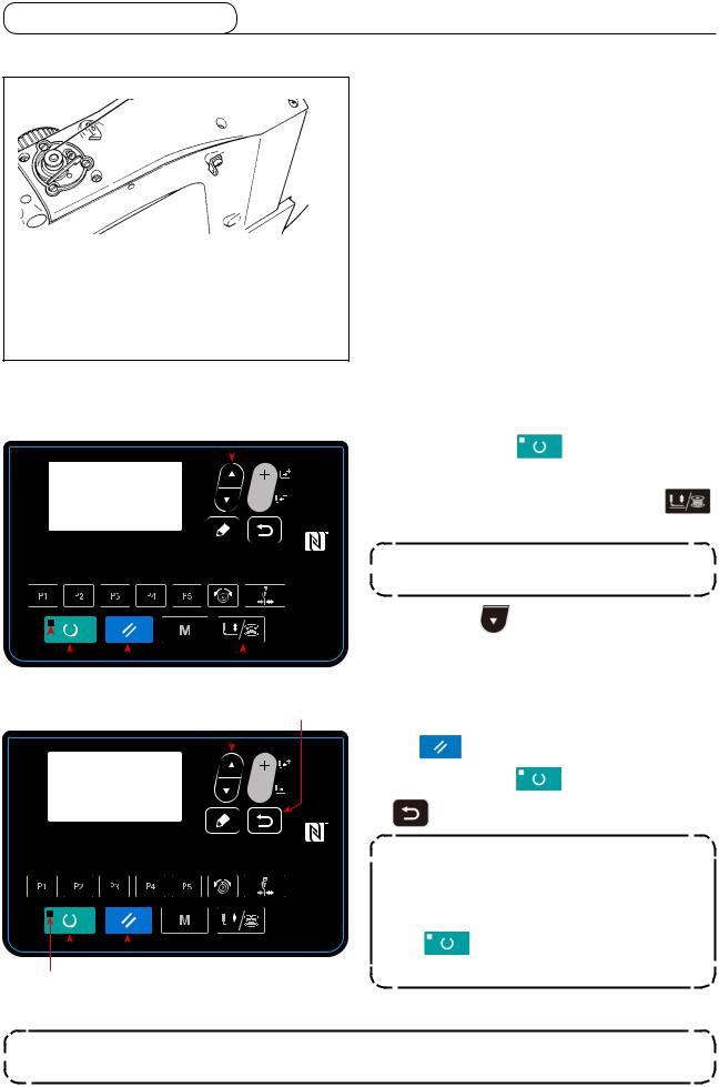
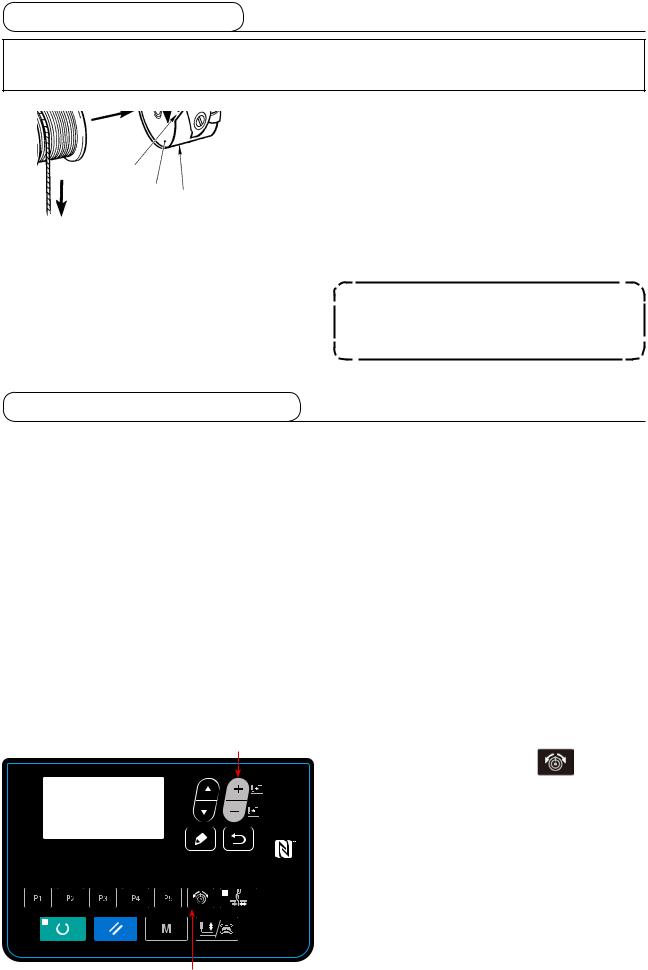
5-7. Winding a bobbin
(1) To wind a bobbin while the sewing machine is performing sewing
Thread the bobbin winder and wind the bobbin thread onto the bobbin as illustrated in the figure.
(2) For winding a bobbin only
|
|
|
|
|
|
|
|
|
|
|
|
|
|
to turn off SET |
|||||||||||
|
|
|
|
|
|
|
|
|
|
|
|
|
|
|
|
|
|
|
|
|
|
1) |
Press READY key |
||
|
|
|
|
|
|
|
|
|
|
|
|
|
|
|
|
|
|
|
|
|
|
|
READY LED . |
|
|
|
|
|
|
|
|
|
|
|
|
|
|
|
|
|
|
|
|
|
|
|
|
2) |
Press work PRESSER and WINDER key |
||
|
|
|
|
|
|
|
|
|
|
|
|
|
|
|
|
|
|
|
|
|
|
||||
|
|
|
|
|
|
|
|
|
|
|
|
|
|
|
|
|
|
|
|
|
|
||||
|
|
|
|
|
|
|
|
|
|
|
|
|
|
|
|
|
|
|
|
|
|
||||
|
|
|
|
|
|
|
|
|
|
|
|
|
|
|
|
|
|
|
|
|
|
|
and select lowering of the work clamp. |
||
|
|
|
|
|
|
|
|
|
|
|
|
|
|
|
|
|
|
|
|
|
|
|
|
Selection cannot be performed when the |
|
|
|
|
|
|
|
|
|
|
|
|
|
|
|
|
|
|
|
|
|
|
|
|
|
SET READY LED is lit up. |
|
|
|
|
|
|
|
|
|
|
|
|
|
|
|
|
|
|
|
|
|
|
|
3) |
Press ▼ key |
. The bobbin winding |
|
|
|
|
|
|
|
|
|
|
|
|
|
|
|
|
|
|
|
|
|
|
|
||||
|
|
|
|
|
|
|
|
|
|
|
|
|
|
|
|
|
|
|
|
|
|
||||
|
|
|
|
|
|
|
|
|
|
|
|
|
|
|
|
|
|
|
|
|
|
||||
|
|
|
|
|
|
|
|
|
|
|
|
|
|
|
|
|
|
|
|
|
|
||||
|
|
|
|
|
|
|
|
|
|
|
|
|
|
|
|
|
|
|
|
|
|
|
screen is displayed. |
||
|
|
|
|
|
|
|
|
|
|
|
|
|
|
|
|
|
|
|
|
|
|
|
|||
|
|
|
|
|
|
|
|
|
|
|
|
|
|
|
|
|
|
|
|
|
|
|
|||
|
|
|
|
|
|
|
|
|
|
|
|
|
|
|
|
|
|
|
|
|
|
4) |
When you depress the pedal, the sewing ma- |
||
|
|
|
|
|
|
|
|||||||||||||||||||
|
|
|
|
|
chine starts rotating. |
||||||||||||||||||||
|
|
|
|
|
|
|
|
|
|
|
|
||||||||||||||
|
|
|
|
|
|
|
|
|
5) |
Depress the pedal switch again or press RESET |
|||||||||||||||
|
|
|
|
|
|
|
|
|
|
|
|
|
|
|
|
|
|
|
|
|
|
||||
|
|
|
|
|
|
|
|
|
|
|
|
|
|
|
|
|
|
|
|
|
|
|
key |
to stop the sewing machine. |
|
|
|
|
|
|
|
|
|
|
|
|
|
|
|
|
|
|
|
|
|
|
|
|
|||
|
|
|
|
|
|
|
|
|
|
|
|
|
|
|
|
|
|
|
|
|
|
6) |
Press READY key |
and RETURN key |
|
|
|
|
|
|
|
|
|
|
|
|
|
|
|
|
|
|
|
|
|
|
|
||||
|
|
|
|
|
|
|
|
|
|
|
|
|
|
|
|
|
|
|
|
|
|
||||
|
|
|
|
|
|
|
|
|
|
|
|
|
|
|
|
|
|
|
|
|
|
|
|
to exit from the bobbin winding screen. |
|
|
|
|
|
|
|
|
|
|
|
|
|
|
|
|
|
|
|
|
|
|
|
|
|
||
|
|
|
|
|
|
|
|
|
|
|
|
|
|
|
|
|
|
|
|
|
|
|
|
Bobbin winder does not work immediately |
|
|
|
|
|
|
|
|
|
|
|
|
|
|
|
|
|
|
|
|
|
|
|
|
|
after turning ON the power. Perform the |
|
|
|
|
|
|
|
|
|
|
|
|
|
|
|
|
|
|
|
|
|
|
|
|
|
bobbin winding after setting pattern No. |
|
|
|
|
|
|
|
|
|
|
|
|
|
|
|
|
|
|
|
|
|
|
|
|
|
||
|
|
|
|
|
|
|
|
|
|
|
|
|
|
|
|
|
|
|
|
|
|
|
|
||
|
|
|
|
|
|
|
|
|
|
|
|
|
|
|
|
|
|
|
|
|
|
|
|
or the like once, pressing the READY key |
|
|
|
|
|
|
|
|
|
|
|
|
|
|
|
|
|
|
|
|
|
|
|
|
|
||
|
|
|
|
|
|
|
|
|
|
|
|
|
|
|
|
|
|
|
|
|
|
|
|
||
|
|
|
|
|
|
|
|
|
|
|
|
|
|
|
|
|
|
|
|
|
|
|
|
, and making the SET READY |
|
|
|
|
|
|
|
|
|
|
|
|
|
|
|
|
|
|
|
|
|
|
|
|
|
||
|
|
|
|
|
|
|
|
|
|
|
|
|
|
|
|
|
|
|
|
|
|
|
|
||
|
|
|
|
|
|
|
|
|
|
|
|
|
|
|
|
|
|
|
|
|
|
|
LED light up. |
||
|
|
|
|
|
|
|
|
|
|
|
|
|
|
|
|
|
|
|
|||||||
 For the LK-1903BN and LK-1903BN/BR35, wind the bobbin after removing the button and needle.
23

5-8. Thread clamp device
Trouble of sewing (slip-off of needle thread, stitch skipping, or stain of needle thread) at the time of highspeed start can be prevented with the thread clamp device. The thread clamp device works in the state that the thread clamp indication LED lights up and does not work when the LED goes off. Changeover of ON/OFF
motion is performed with THREAD CLAMP key  . When the thread clamp device is OFF, the start automatically becomes the slow start.
1. When memory switch No. 35 is "1" (prohibited), the thread clamp does not work. In addition, THREAD CLAMP key  is ineffective.
2.Memory switch, refer to "I.8. HOW TO USE THE MEMORY SWITCH" p.56.
*Matters that demand special attention when using the needle thread clamp device
(1)In case of with the needle thread clamp (motion), make shorter the length of needle thread remaining on the needle at the sewing start for use. When the length of needle thread is lengthened, needle thread on the wrong side of material is apt to protrude. In addition, when the length is excessively lengthened, the end of needle thread held by the needle thread clamp may be rolled in the seams.
1)
33 to 36mm
3)
1)In case of with the needle thread clamp, the standard of the length of needle thread is 33 to 36 mm.
2)When needle thread is long after replacing thread or the like or sewing while holding needle thread by hand, turn OFF the THREAD CLAMP key  .
.
3)When the needle thread held with the thread clamp is rolled in the seams, do not draw the material forcibly and cut the connecting needle thread with the scissors or the like. The seams are not damaged since it is the needle thread at the sewing start.
(Right side)
10mm
(Wrong side)
Needle thread
(2)It is possible to adjust needle thread shorter by making the needle thread clamp work while holding the stabilized sewing at the start of sewing and the gathering (bird's nest) of needle thread on the wrong side of material can be lessened. However, for the pattern which the stitch length for neatly rolling in needle thread is short, needle thread may protrude from the wrong side of material. Select with/without thread clamp referring to the item below.
1)When the sewing length is short (less than approximately 10 mm), the end of needle thread may protrude like beard even when adjusting needle thread shorter.
24

(3)In the case feed plate which prevents the material from coming in close contact with throat plate is used, the needle thread which appears on the wrong side of the material can run off the seam regardless of the sewing length.
(Wrong side)
Needle thread
(4)For LK-1903BN (button sewing), the thread clamp is set to the motion prohibited in the state of standard
delivery due to the aforementioned (2) and (3). For (memory switch No. 35) with cross-over stitch (  ,
,
etc.) or X shape (  , etc.), needle thread on the wrong side of material becomes easy to be rolled in. In this case, it is recommended to use the thread clamp.
(5)When the thread clamp is used, and bobbin thread at the sewing start appears on the right side of material, reduce thread tension at the sewing start (2 to 3 stitches) and bobbin thread becomes less conspicuous.
[Example of setting] Tension of 1 to 2 stiitches at the sewing start is “20” when sewing tension setting is “35”.
*For the setting of tension at the sewing start, refer to "I.6-5. Setting the pattern thread tension" p.39.
25

5-9. LED hand light
WARNING :
In order to protect against personal injury due to unexpected start of the sewing machine, never bring hands near the needle entry area or place foot on the pedal during the adjustment of intensity of the LED.
This LED is intended to improve operability of the sewing machine and is not intended for maintenance.
If the LED light is too bright when sewing a narrow sewing material or changing over the sewing material on the sewing machine, the LED light should be dimmed or turned OFF.
The sewing machine is provided as standard with an LED light which illuminates the needle entry area. Intensity adjustment and turn-off of the light is carried out by pressing switch . Every time the switch is pressed, the light is adjusted in intensity in five steps and is turned off in turn.
[Change of intensity]
|
1 ...... |
4 5 |
1 |
|
Bright ...... |
Dim Off |
Bright |
In this way, every time the switch is pressed, the hand lamp status is changed in repetition.
26

6. OPERATION OF THE SEWING MACHINE (ADVANCED)
6-1. Performing sewing using the pattern keys
Patterns (No.1 to 200) which have been already registered can be registered to P1 to P50. It is possible to change and register the scale, max. speed limitation, thread tension and sewing position. Same as the patterns (No.1 to 200), P1 to P25 are used by the selection by scrolling the pattern Nos. The pattern calling from P1 to P25 can be made by one-touch as well.
*When selecting P6 to P25, perform the selection by combination (simultaneous pressing) of 


 and
and  keys as shown in the table below.
P-No. |
Selection key |
P-No. |
Selection key |
P-No. |
Selection key |
P-No. |
Selection key |
P1 |
P1 |
P8 |
P1+P4 |
P15 |
P4+P5 |
P22 |
P2+P3+P4 |
P2 |
P2 |
P9 |
P1+P5 |
P16 |
P1+P2+P3 |
P23 |
P2+P3+P5 |
P3 |
P3 |
P10 |
P2+P3 |
P17 |
P1+P2+P4 |
P24 |
P2+P4+P5 |
P4 |
P4 |
P11 |
P2+P4 |
P18 |
P1+P2+P5 |
P25 |
P3+P4+P5 |
P5 |
P5 |
P12 |
P2+P5 |
P19 |
P1+P3+P4 |
|
|
P6 |
P1+P2 |
P13 |
P3+P4 |
P20 |
P1+P3+P5 |
|
|
P7 |
P1+P3 |
P14 |
P3+P5 |
P21 |
P1+P4+P5 |
|
|
(1) Register to the pattern key
Setting example : Register following setting to the P2., Pattern No. 3, X scale rate : 50%, Y Scale rate : 80%, Max. speed limitation : 2,000 sti/min, Thread tension : "50", Pattern position : 0.5 mm to the right and 1 mm to the front
1)Turn ON the power switch and press MODE key
 to enter mode setting (memory switch setting). (SET READY LED should be put out.)
Press ITEM SELECT key |
to select "04 |
Direct pattern regist".
Press EDIT key  to display the pattern registration mode.
2) Press ITEM SELECT key |
to set the |
standard pattern to No. 3. Press DATA CHANGE
key  to set P-No. to 2.
When you press the READY key  , P2 is registered and the mode screen is displayed. Press MODE key
  or RETURN key
 .
.
*When the select key is held pressed for one second in the state where the standard pattern or user pattern is selected on the data input screen, this screen can be displayed.
27
Loading...