


 Loading...
LK-1903BN/BR35
INSTRUCTION MANUAL
|
CONTENTS |
|
I. SPECIFICATIONS...................................................................................................................... |
1 |
|
1. |
Specifications................................................................................................................................................. |
1 |
2. |
Model classification according to the button size...................................................................................... |
2 |
3. |
Shape of buttons............................................................................................................................................ |
2 |
II. NAME OF EACH COMPONENT............................................................................................... |
3 |
|
III. INSTALLATION OF THE SEWING MACHINE AND PREPARATION OF THE OPERATION.4 |
||
1. |
Installation of the table and stand................................................................................................................ |
4 |
2. |
Needle and thread.......................................................................................................................................... |
4 |
3. |
Attaching the needle...................................................................................................................................... |
4 |
4. |
Threading the machine.................................................................................................................................. |
5 |
IV. OPERATION............................................................................................................................. |
6 |
|
1. |
Operation of the sewing machine................................................................................................................. |
6 |
2. |
Various sewing modes.................................................................................................................................. |
6 |
3. |
Operation of the button feeder unit.............................................................................................................. |
8 |
4. |
Operation...................................................................................................................................................... |
10 |
5. |
How to set the DIP switches and the digital switches.............................................................................. |
10 |
V. MAINTENANCE...................................................................................................................... |
16 |
|
1. |
Tilting the sewing machine head................................................................................................................ |
16 |
2. |
Position of the button clamp jaw lever...................................................................................................... |
17 |
3. |
Adjusting the feed plate.............................................................................................................................. |
18 |
4. |
Adjusting the button clamp jaw lever........................................................................................................ |
18 |
5. |
Adjusting the lifting amount of the button clamp..................................................................................... |
19 |
6. |
Adjustment of the pressure of the work clamp unit................................................................................. |
20 |
7. |
Adjustment of the wiper.............................................................................................................................. |
20 |
8. |
Adjustment of the wiper spring.................................................................................................................. |
20 |
9. |
Installing the save button bar (accessory part)........................................................................................ |
21 |
10. Adjustment of the button feeder unit control box..................................................................................... |
21 |
|
11. |
Detecting mechanism of the button feeder components and the adjustment....................................... |
22 |
12. Adjusting the feed plate of the index unit.................................................................................................. |
23 |
|
13. Replacing the button feeder components and positioning them............................................................ |
24 |
|
14. Adjusting the vibration of the button feeder............................................................................................. |
25 |
|
15. Adjusting the feeder bowl components..................................................................................................... |
25 |
|
16. How to replace the buttons (on the button feeder side)........................................................................... |
28 |
|
VI. ALARM NO. INDICATION (on the button feeder unit (BR) side)....................................... |
30 |
|
VII. TROUBLES AND CORRECTIVE MEASURES IN BR......................................................... |
31 |
|
VIII. OPTIONAL PARTS.............................................................................................................. |
32 |
|
1. |
Kinds of the button carrier.......................................................................................................................... |
32 |
2. |
Attachment................................................................................................................................................... |
33 |
3. |
Others............................................................................................................................................................ |
34 |
i
I. SPECIFICATIONS
Different specifications from those of the LK-1900BN only are described.
1. Specifications
1 |
Sewing speed |
Max. 2,700 sti/min (Normal speed : 2,500 sti/min) |
|
|
|
|
|
2 |
Needle bar stroke |
45.7 mm |
|
3 |
Needle |
DPX17 #14 |
|
|
|
|
|
4 |
Lifting lever method |
Joint use of stepping motor and cam (BR side) |
|
|
|
|
|
5 |
Lifting amount of button clamp |
Max. 11 mm |
|
6 |
Number of standard patterns |
50 kinds |
|
|
|
|
|
7 |
Sewing speed limit |
Can be limited freely to 400 to 2,700 sti/min. |
|
|
|
(adjustable in a unit of 100 sti/min) |
|
|
|
|
|
8 |
Buttons used |
Type |
: Round-shaped flat buttons (4-holed, 2-holed) |
|
|
Size |
: ø10 mm to ø18 mm |
|
|
(Note) 1. For buttons of which diameter is ø16 mm or more, the stan- |
|
|
|
|
dard feed plate is required to be replaced with the feed plate |
|
|
|
22B asm. |
|
|
2. For buttons of which diameter is ø16 mm or more, use the |
|
|
|
|
button clamp jaw lever for large buttons. |
|
|
Thickness : 1.8 to 3.5 mm |
|
9 |
Selection of buttons to be fed |
By vibration system using a piezoelectric feeder |
|
|
|
|
|
10 |
Button setting |
Buttons are loaded from the rear. (Manual loading possible) |
|
|
|
|
|
11 |
Button feeding method |
Horizontal forced feed mechanism |
|
12 |
Detection of a failure of feeding buttons |
Provided with two detectors |
|
|
|
• One detector detects a button at the section where the button is cor- |
|
|
|
rectly positioned. |
|
|
|
• Another detector checks whether the button is correctly inserted into |
|
|
|
the carrier pin. |
|
|
|
|
|
13 |
Driving source for the feeder |
DC motor (24 Vdc) |
|
|
|
|
|
14 |
Automatic button discharging function |
Provided |
|
15 |
Independent operation |
Possible |
|
|
of the sewing machine |
|
|
|
|
|
|
16 |
Small-lot sewing function |
Provided |
|
|
|
|
|
17 |
Time required to feed a button |
0.5 sec/pc. |
|
18 |
Outer dimension |
W : 1,200 mm L : 660 mm H : 1,155 mm |
|
|
|
(Standard table and stand used) |
|
|
|
|
|
19 |
Mass |
135 kg (including optional table/stand) |
|
|
|
|
|
20 |
Power fluctuation |
Rated value ±10 % 50/60 Hz |
|
21 |
Power consumption |
350 W |
|
|
|
|
|
22 |
Noise |
- Equivalent continuous emission sound pressure level (LpA) at the workstation : |
|
|
|
A-weighted value of 81.0 dB; (Includes KpA = 2.5 dB); according to ISO |
|
|
|
10821- C.6.3 -ISO 11204 GR2 at 2,700 sti/min for the sewing cycle, 1.8s |
|
|
|
ON (Pattern : No.4). |
|
|
|
- Sound power level (LWA) ; |
|
|
|
A-weighted value of 83.5 dB; (Includes KWA = 2.5 dB); according to ISO |
|
|
|
10821- C.6.3 -ISO 3744 GR2 at 2,700 sti/min for the sewing cycle, 1.8s |
|
|
|
ON (Pattern : No.4). |
|
|
|
|
|
− 1 −
2. Model classification according to the button size
|
|
Model |
|
|
LK-1903BN-311 |
|
|
LK-1903BN-312 |
|
|
|
|
|
|
|
|
|
|
|
|
|
Button size classification |
|
|
|
|
For small-sized buttons |
|
|
For medium-sized buttons |
|
|
|
|
|
|
|
|
|
|
|
|
|
Outside diameter of applicable buttons (mm) |
|
|
ø10 - ø15 |
|
|
ø12 - ø18 |
|
|||
|
|
|
|
|
|
|
|
|
|
|
Sewing size (mm) |
|
Length |
|
|
0 - 3.5 |
|
|
0 - 4.5 |
|
|
|
|
|
|
|
|
|
|
|
|
|
|
Width |
|
|
0 - 3.5 |
|
|
0 - 4.5 |
|
||
|
|
|
|
|
|
|
||||
|
|
|
|
|
|
|
|
|
|
|
Button clamp jaw |
|
Thickness (mm) |
|
2.2 |
Engraved mark |
2.7 |
Engraved mark |
|||
|
|
|
|
|
|
|
|
|
|
|
|
Part No. |
|
Right |
|
MAZ165070B0 |
H |
|
MAZ166070B0 |
J |
|
lever |
|
|
|
|
||||||
|
|
Left |
|
MAZ165080B0 |
H |
|
MAZ166080B0 |
J |
||
|
|
|
|
|
|
|||||
Needle hole guide |
|
|
|
|
MAZ15501000 |
|
|
MAZ15601000 |
|
|
|
|
|
|
|
|
|
|
|
|
|
Feed plate |
|
|
|
|
MAZ15502000 |
|
|
MAZ15602000 |
|
|
|
|
|
|
|
|
|
|
|
|
|
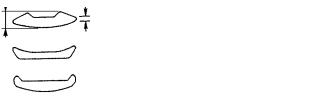
3. Shape of buttons
|
|
Applicable buttons |
Non-applicable buttons |
|
|
|
|
|
1.8 – |
1.2 mm or more |
Less than 1.2 mm |
|
|
||
Shape of buttons |
3.5 mm |
|
|
|
|
||
|
|
|
|
|
|
|
Button without recess on the surface |
|
|
|
|
Remarks |
Thickness of button : 1.8 to 3.5 mm |
Button of which edge is thin is likely not to be fed smoothly. |
|
|
|
|
|
− 2 −

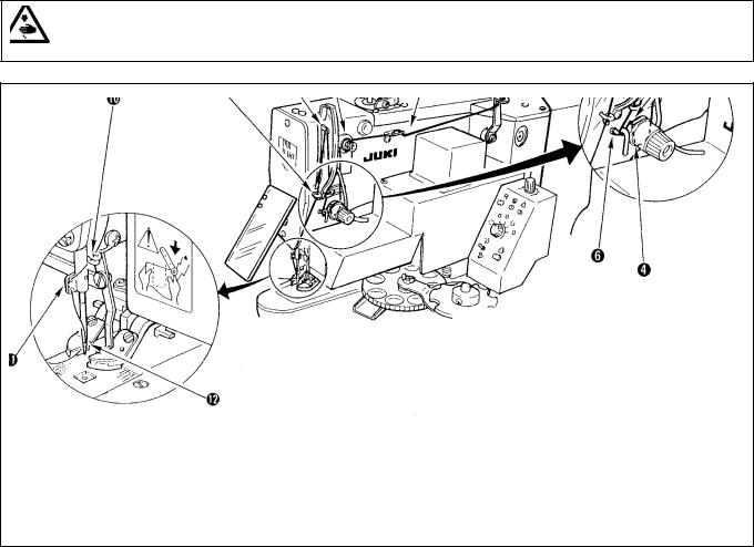
II. NAME OF EACH COMPONENT
This machine is composed of the following components.
Button clamp
Table
Button loader
Spinner
arm
Thread stand
Buton feeder
Sewing machine
feeder controller Europe)
Foot pedal |
Power switch |
Power switch ( EU type)
− 3 −

III. INSTALLATION OF THE SEWING MACHINE AND PREPARATION OF THE OPERATION
As for the descriptions other than those described in the following items, refer to the Instruction Manual for the LK-1900BN.
1. Installation of the table and stand
WARNING :
Turn OFF the power before starting the work so as to prevent accidents caused by abrupt start of the sewing machine.
(Caution) 1. Be sure to install the table and stand on a flat place.
2.After the installation, be sure to fix the table and stand by locking the casters or adjusting the adjuster.
3.When adjusting the height of the table, perform the work by two persons or more so as not to drop the table.
2.Needle and thread
Needle |
Needle thread |
Bobbin thread |
|
|
#60 |
#80 |
|
DP x 17 #14 |
#50 |
#60 |
|
#40 |
#60 |
||
|
|||
|
#60 |
#60 |
|
|
|
|
Needle and thread will vary in accordance with the sewing conditions. When using the needle and the thread, select them referring to the left table. Cotton thread and spun thread are recommended.
3. Attaching the needle
WARNING :
Turn OFF the power before starting the work so as to prevent accidents caused by abrupt start of the sewing machine.
To attach the needle, loosen screw , insert needle fully into the needle bar hole with the long groove facing toward you, then tighten screw .
− 4 −
4. Threading the machine
WARNING :
Turn OFF the power before starting the work so as to prevent accidents caused by abrupt start of the sewing machine.
− 5 −

IV. OPERATION
1. Operation of the sewing machine
As for the operation of the sewing machine, refer to the Instruction Manual for the LK-1900BN.
WARNING :
•When performing the selection of the pattern or enlargement/reduction of the sewing width, make sure of the needle entry point. If the needle extends outside the button hole or the sewing pattern extends outside the button clamp unit, the needle interferes with the button hole or the button clamp unit during sewing, resulting in the danger of the needle breakage or the like.
•While checking the shape of the pattern, do not depress the pedal upto the second step. Sewing will start by so depressing the pedal. So, be careful.
2.Various sewing modes
(1)Selection of the sewing pattern and the sewing width
•Selection of the sewing pattern is the same as that of the LK-1900BN.
•When the distance between holes of the button used does not fit the standard sewing width of the sewing pattern No., adjust the sewing width by enlarging/reducing the sewing width.
The way of enlarging/reducing is the same as that of the LK-1900BN. Refer to the table given below for the scale for enlargement/reduction in terms of the sewing width.
•As for the way of confirmation of the needle entry, refer to the confirmation of the shape of sewing pattern in the Instruction Manual for the LK-1900BN.
(Caution) |
When ascertaing the needle entry point of the sewing pattern, there is a section of jump feed of one |
|||||||||||||||
|
|
stitch before the needle mouse from the origin (center of the button) to the first stitch. |
|
|
||||||||||||
Table of XY scales in terms of the sewing width |
|
|
|
|
|
|
|
|
|
|
||||||
|
|
|
|
|
|
|
|
|
|
|
|
|
|
|
|
|
X, Y |
2.4 |
2.6 |
2.8 |
3.0 |
3.2 |
3.4 |
3.6 |
4.0 |
4.3 |
4.5 |
4.7 |
5.2 |
5.6 |
6.0 |
6.2 |
6.4 |
(mm) |
||||||||||||||||
|
|
|
|
|
|
|
|
|
|
|
|
|
|
|
|
|
% |
71 |
76 |
82 |
88 |
94 |
100 |
106 |
118 |
126 |
132 |
138 |
153 |
165 |
176 |
182 |
188 |
|
|
|
|
|
|
|
|
|
|
|
|
|
|
|
|
|
(2) Soft-start
Setting of the soft-start speed at the start of sewing of this machine is “1st stitch : 400 sti/min, and 2nd stitch : 900 sti/min” only at the time of standard delivery.
When slip-off of thread at the start of sewing or the like occurs, increase the number of stitches of the soft-start in accordance with the thread used and sewing products for use.
For the setting procedure of the soft-start, refer to “I.8-1. Method of changing memory switch data” of the Instruction Manual for LK-1900BN.
(3) Thread clamp
Thread clamp device of this machine is set to thread clamp motion prohibited (memory switch) at the time of standard delivery.
When the thread clamp device is actuated, high-speed start or prevention of slip-off of needle thread at the start of sewing can be performed. However, there are some matters that demand special attention. When using the machine, refer to “I.5-8. Thread clamp device” of the Instruction Manual for LK-1900BN.
− 6 −

(2) Sewing patterns
Number of threads and standard sewing size of X and Y are as shown in the following list.
<Sewing program list>
Pattern No. Stitch |
Number |
Standard |
Standard |
Pattern No. Stitch |
Number |
Standard |
Standard |
shape |
of threads |
sewing size |
sewing size |
shape |
of threads |
sewing size |
sewing size |
|
(thread) |
X (mm) |
Y (mm) |
|
(thread) |
X (mm) |
Y (mm) |
1-34 |
6-6 |
|
|
18-44 |
6 |
|
|
|
|
|
|
|
|
|
|
2-35 |
8-8 |
|
|
19-45 |
8 |
|
|
|
|
|
|
|
|
|
|
3 |
10-10 |
|
|
20 |
10 |
3.4 |
0 |
|
|
|
|
|
|
|
|
4 |
12-12 |
|
|
21 |
12 |
|
|
|
|
|
|
|
|
|
|
5-36 |
6-6 |
|
|
22 |
16 |
|
|
|
|
|
|
|
|
|
|
6-37 |
8-8 |
|
|
23-46 |
6 |
|
|
|
|
3.4 |
3.4 |
|
|
|
|
7 |
10-10 |
24 |
10 |
0 |
3.4 |
||
|
|
|
|
|
|
|
|
8 |
12-12 |
|
|
25 |
12 |
|
|
|
|
|
|
|
|
|
|
9-38 |
6-6 |
|
|
26-47 |
6-6 |
|
|
|
|
|
|
|
|
3.4 |
3.4 |
10-39 |
8-8 |
|
|
27 |
10-10 |
||
|
|
|
|
|
|
|
|
11 |
10-10 |
|
|
28-48 |
6-6 |
|
|
|
|
|
|
|
|
|
|
12-40 |
6-6 |
|
|
29 |
10-10 |
|
|
|
|
|
|
|
|
|
|
13-41 |
8-8 |
|
|
30-49 |
5-5-5 |
|
|
|
|
|
|
|
|
2.9 |
2.5 |
14 |
10-10 |
|
|
31 |
8-8-8 |
||
|
|
|
|
|
|
|
|
15-42 |
6-6 |
|
|
32-50 |
5-5-5 |
|
|
|
|
|
|
|
|
|
|
16-43 |
8-8 |
|
|
33 |
8-8-8 |
|
|
17 10-10
*The standard sewing sizes of X and Y are when the enlargement/reduction rate is 100%. Use pattern No. 34 to No. 50 when the button hole is small (ø 1.5 mm or less).
− 7 −
3. Operation of the button feeder unit
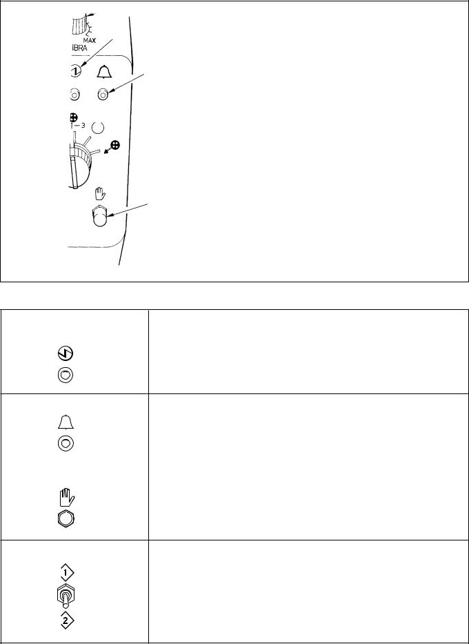
(1) Explanation of the button feeder unit control panel
Parts feeder controller (For Europe)
Symbol and name of switch |
Function |
|
|
Power indicator lamp (green) |
Lights up when the power switch is turned ON. If it fails to light up, check the power plug for |
|
secure connection and re-turn ON the power switch. |
Alarm indicator lamp (red) |
It slowly flashes on and off |
: When a failure of operation occurs. (Refer to “Alarm No. |
|
|
|
indication”.) |
|
|
(Note) It flashes on and off even in a state that the sewing LED on the sewing machine |
||
|
operation box goes out. |
||
|
It quickly flashes on and off |
: When the button sensor on the index unit continuously detects |
|
|
|
button feeding failure over 10 times. |
|
|
|
||
MANUAL operation switch |
Used to manually actuate the series of operations under respective operation modes (“2. |
||
Independent sewing mode” is excluded.) which can be selected using mode selector switch . |
|||
|
|||
Inspection switch |
Normally, this switch does not function. |
|
It is used to inspect the drive source and the sensors. |
− 8 −
Symbol and name of switch |
Function |
|
|
Mode selector switch |
1. Automatic sewing mode |
|
The sewing machine and the button feeder operate with interlocked. Under this operation |
|
mode, depressing the foot pedal lowers the button clamp and makes the sewing machine |
|
start sewing a button. When the machine completes sewing of the button, the thread trimmer |
|
actuates, then the button feeder actuates to feed next button to be sewn. This series of |
|
operations is repeated under the automatic sewing mode. |
2. Independent sewing mode 
This mode allows the sewing machine to independently operate. Under this mode, the operator sets the button to be sewn in the button clamp on the machine by hand. Then, depressing the foot pedal lowers the button clamp and makes the machine start sewing the button. When the machine completes sewing of the button, the thread trimmer actuates then the button clamp goes up.
3. Small-lot sewing mode 
Basically, series of operations performed under this mode is the same as that under the automatic sewing mode. The parts feeder, however, does not operate under this mode. The operator manually feeds buttons by the number desired to be sewn to the gear of index unit and let the machine perform button sewing.
|
4. Prospective button feeding mode |
||||||||||
|
Under this mode, the fine positioning completion sensor function is stopped and the machine |
||||||||||
|
performs fine positioning of a button in a predetermined period of time (set by DEG-SW-2.). |
||||||||||
|
|
|
|
|
|
|
|
|
|
|
a |
|
|
|
|
|
|
|
|
|
|
|
a = Suited to buttons of which is 1 mm or more. |
|
|
|
|
|
|
|
|
||||
|
|
|
|
|
|
|
|
|
|
|
|
|
5. Button discharging mode |
||||||||||
|
Under this mode, buttons in the index unit are automatically discharged by pressing manual |
||||||||||
|
opration switch . In this case, the button is discharged to the discharging chute located |
||||||||||
|
at the lower section of the button positioner. So, place a pan or the like to receive the |
||||||||||
|
discharged buttons at the exit area. At this time, do not place your fingers around the button |
||||||||||
|
clamp unit until the operation completes since the button carrier actuates. |
||||||||||
|
|
|
|
|
|
|
|
|
|
|
|
Reset switch |
Press this switch to reset the machine from its error stop state to its normal operative state. |
||||||||||
R |
(Note that alarm Nos. 4 and 5 cannot be reset using the reset switch. Turn OFF the power |
||||||||||
|
once, eliminate the cause of the trouble and re-turn ON the power to the machine.) |
||||||||||
|
|
|
|
|
|
|
|
|
|
|
|
Parts feeder (P/F) adjusting variable |
Used to adjust the flow of buttons in the feeder bowl. |
||||||||||
resistordell’alimentatore parti (P/F) |
(Note) For the European specifications only, adjustment is performed with a separate |
||||||||||
|
control box. |
||||||||||
MIN MAX
− 9 −
4. Operation
(Caution) Move the button clamp jaw levers near to the position of the needle center in advance.
1)Turn ON the power to the main unit of the sewing machine.
At this time, the alarm indication on the button feeder unit control panel flashes on and off, and the alarm indication on the button feeder unit control box indicates “0” (flashing).
2)Press the [Ready] key on the sewing machine operation box, and the sewing LED lights up to release the alarm indication on the unit. Then the button clamp jaw levers move to the origin and go up. (A state that the sewing is possible.)
3)Press the manual operation switch on the button feeder unit control panel, and supply the button clamp jaw levers with a button. If the button is not supplied to the button clamp jaw levers, press the manual operation switch again.
4)When depressing the pedal to the first step, the button clamp jaw levers come down. At this time, make sur of the sewing position. (If you release your foot from the pedal, the button clamp jaw levers go up.)
5)Furthermore depressing the pedal makes the sewing machine perform sewing the button in accordance with the pattern No.
6)When the sewing is completed, the button clamp jaw levers go up, the button carrier of button supply unit turns, and a button is supplied.
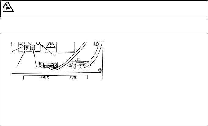
5.How to set the DIP switches and the digital switches
WARNING :
Turn OFF the power before starting the work so as to prevent accidents caused by abrupt start of the sewing machine.
Loosen two screws , and open panel as illustrated in the following figure to change the setting of the respective switches.
Button feeder unit control box
BR35
DIP switch (DIP-SW)
Digital switch (DEG-SW-1)Digital switch (DEG-SW-2)
|
|
− 10 −
Loading...