


 Loading...
LU-2828-7, 2828-6
INSTRUCTION MANUAL
CONTENTS |
|
1. SPECIFICATIONS...................................................................................................... |
1 |
2. INSTALLATION.......................................................................................................... |
2 |
2-1. Installation of the sewing machine.................................................................................... |
2 |
2-2. Installing the belt cover and the belt (LU-2828-6)............................................................ |
5 |
2-3. Adjusting the belt tension (LU-2828-6).............................................................................. |
6 |
2-4. Installing the synchronizer (LU-2828-6)............................................................................ |
6 |
2-5. Adjusting the synchronizer (LU-2828-6)............................................................................ |
7 |
2-6. Installing the oil shield........................................................................................................ |
8 |
2-7. Pneumatic components...................................................................................................... |
8 |
2-8. Wiring the machine head (LU-2828-6)............................................................................. |
10 |
2-9. Installing the thread stand................................................................................................ |
14 |
2-10. Installing the thread guide pin....................................................................................... |
14 |
3. PREPARATION OF THE SEWING MACHINE......................................................... |
15 |
3-1. Lubrication......................................................................................................................... |
15 |
3-2. Attaching the needle......................................................................................................... |
17 |
3-3. Attaching and removing the bobbin................................................................................ |
17 |
3-4. Threading the hook........................................................................................................... |
18 |
3-5. Winding a bobbin.............................................................................................................. |
18 |
3-6. Threading the machine head............................................................................................ |
19 |
3-7. How to set the model of the machine head (LU-2828-7)................................................ |
20 |
3-8. Adjusting the machine head (LU-2828-7).......................................................................... |
22 |
4. ADJUSTING THE SEWING MACHINE.................................................................... |
24 |
4-1. Adjusting the stitch length............................................................................................... |
24 |
4-2. Thread tension................................................................................................................... |
25 |
4-3. Thread take-up spring....................................................................................................... |
26 |
4-4. Adjusting the pressure of the presser foot..................................................................... |
27 |
4-5. Needle-to-hook relation.................................................................................................... |
28 |
4-6. Adjusting the hook needle guard..................................................................................... |
29 |
4-7. Adjusting the bobbin case opening lever....................................................................... |
29 |
4-8. Adjusting the moving knife, the counter knife and the bobbin thread clamp............. |
30 |
4-9. Adjusting the thread trimming cam timing..................................................................... |
32 |
4-10. Adjusting the condensation stitch................................................................................. |
33 |
4-11. Adjusting the amount of the alternating vertical movement of the walking foot and |
|
the presser foot................................................................................................................ |
34 |
5. OPERATION OF THE SEWING MACHINE............................................................. |
34 |
5-1. Hand lifter........................................................................................................................... |
34 |
5-2. Resetting the safety clutch............................................................................................... |
34 |
5-3. Adjusting the automatic presser foot lifter..................................................................... |
35 |
5-4. Fixing the feed adjusting dial........................................................................................... |
36 |
5-5. Normal-/reverse-feed stitch needle entry points alignment at the time of automatic |
|
reverse feed stitching...................................................................................................... |
37 |
5-6. Operation switches........................................................................................................... |
38 |
5-7. Knee switch....................................................................................................................... |
40 |
5-8. Function setting for the SC-922 (LU-2828-7).................................................................. |
43 |
6. SEWING SPEED TABLE.......................................................................................... |
46 |
7. TROUBLES IN SEWING AND CORRECTIVE MEASURES................................... |
47 |
i

1. SPECIFICATIONS
No. |
Item |
|
Application |
|
|
|
|
|
|
1 |
Model |
|
LU-2828-7 |
LU-2828-6 |
|
|
|
|
|
2 |
Model name |
|
1-needle, unison-feed, lockstitch |
1-needle, unison-feed, lockstitch |
|
|
|
machine with automatic thread trimmer |
machine with automatic thread trimmer |
|
|
|
(with 2.7-fold vertical axis hook/needle |
(with 2.7-fold vertical axis hook/needle |
|
|
|
thread clamp function/direct drive type) |
thread clamp function/V belt type) |
|
|
|
|
|
3 |
Application |
|
Mediumto heavy-weight materials, car seat, furniture |
|
|
|
|
|
|
4 |
Sewing speed |
|
Max. 3,000 sti/min |
|
|
|
|
(See "6. SEWING SPEED TABLE" p.46.) *1 |
|
|
|
|
|
|
5 |
Needle |
|
SCHMETZ 134-35 (Nm 125 to Nm 180) (Standard : Nm 140) |
|
|
|
|
|
|
6 |
Applicable thread size for sewing |
|
#30 to #5 |
|
|
|
|
|
|
7 |
Applicable thread size to be cut |
|
#30 to #5 |
|
|
|
|
|
|
8 |
Stitch length |
|
Max. 9 mm (forward/reverse feed) |
|
|
|
|
|
|
9 |
Stitch length dial |
|
2-pitch dial |
|
|
|
|
|
|
10 |
Presser foot lift |
|
Hand lifter : 10 mm |
|
|
|
|
Automatic presser foot lifter : 20 mm |
|
|
|
|
|
|
11 |
Stitch length adjusting |
|
By dial |
|
|
mechanism |
|
|
|
|
|
|
|
|
12 |
Reverse stitch adjusting method |
|
Air cylinder type (with touch-back switch) |
|
|
|
|
|
|
13 |
Thread take-up |
|
Link thread take-up |
|
|
|
|
|
|
14 |
Needle bar stroke |
|
40 mm |
|
|
|
|
|
|
15 |
Amount of the alternate vertical |
|
1 mm to 9 mm (Alternate vertical dial adjustment type) |
|
|
movement |
|
|
|
|
|
|
|
|
16 |
Hook |
|
Full-rotary vertical-axis 2.7-fold hook (Latch type) |
|
|
|
|
|
|
17 |
Feed mechanism |
|
Box feed |
|
|
|
|
|
|
18 |
Top and bottom feed actuation |
|
Timing belt |
|
|
mechanism |
|
|
|
|
|
|
|
|
19 |
Thread trimming method |
|
Cam-driven scissors type |
|
|
|
|
|
|
20 |
Lubrication |
|
Automatic lubrication by oil tank (with oil gauge) |
|
|
|
|
|
|
21 |
Lubricating oil |
|
JUKI New Defrix Oil No. 1 (equivalent to ISO standard VG7) |
|
|
|
|
or JUKI MACHINE OIL No. 7 |
|
|
|
|
|
|
22 |
Bed size |
|
643 mm × 178 mm |
|
|
|
|
|
|
23 |
Space under the arm |
|
347 mm × 127 mm |
|
|
|
|
|
|
24 |
Hand wheel size |
|
Outer diameter : ø123 mm |
|
|
|
|
|
|
25 |
Motor/Control box |
|
SC-922B |
- |
|
|
|
|
|
26 |
Machine head weight |
|
62 kg |
|
|
|
|
|
|
27 |
Rated power consumption |
|
180VA |
|
|
|
|
|
|
28 |
Noise *2 |
- |
Equivalent continuous emission sound pressure level (LpA) at the workstation: |
|
|
|
|
A-weighted value of 81.0 dB; (Includes KpA = 2.5 dB); according to ISO |
|
|
|
|
10821- C.6.2 - ISO 11204 GR2 at 3,000 sti/min. |
|
|
|
- |
Sound power level (LWA); |
|
|
|
|
A-weighted value of 85.5 dB; (Includes KWA = 2.5 dB); according to ISO |
|
|
|
|
10821- C.6.2 - ISO 3744 GR2 at 3,000 sti/min. |
|
|
|
|
|
|
*1 The speed setting according to the amount of the alternating vertical movement of the walking foot and presser foot is automatically carried out.
*2 The noise level show in the table is the level generated in the case JUKI's control box (SC-922) is used.
– 1 –
2. INSTALLATION
2-1. Installation of the sewing machine
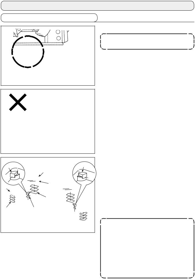
1) Carry the sewing machine with two persons.
Do not hold the pulley and the reverse feed lever.
2) Do not put protruding articles such as the screwdriver and the like at the location where the sewing machine is placed.
|
|
|
3) Attaching the hinge seats and the support rub- |
|
|
|
bers of the machine head |
|
|
Place sheets A and B (standard: three pieces) |
|
|
|
|
and C (standard: one piece) between hinge seat |
|
|
|
and machine head support rubbers and . |
|
|
Then, fix them on the table with nail . |
|
|
Sheet A |
|
There are two different machine head support |
|
|
rubbers ; i.e., the rubber for the right and that |
|
Sheet B |
Sheet C |
|
for the left. Be sure to check the types of the |
|
support rubbers before fixing them. |
||
|
|
|
Sheets A and B (eight pieces each) and sheets C (four pieces) are supplied with the machine as accessories.
For the sheets A and B, three sheets are to be used as standard for each mounting position. For the sheet C, one sheet is to be used as standard. (The state shown in the left figure)
The sheets A, B and C are used for adjusting the height of the top surface of the bed. Use one more sheet to increase the height, or use only one sheet to decrease it.
– 2 –

Operator’s side |
Align |
Table |
Align
Multi-layered part
Top surface

4)Attaching the oil pan
Fix the oil pan supplied with the machine on the table by tightening ten wood screws.
5)Attach a filter to the oil pan as shown in
the figure.
Install filter so that its multi-layered part is brought to the right side as observed from you.
6)Install hinge on the bed with screw . Engage the hinge with the rubber hinge of the table. Then, place the machine head on the machine head support rubber.
– 3 –


A

7)Securely attach head support rod until its rib is closely pressed against the table.
8)Put reflux pipe in the oil reservoir A of oil pan . Secure the pipe in groove .
9)Fix filter and filter clamp with fitting .
10)Mount spacers supplied with the machine head on the frame.
11)Install bracket on CP panel with screws supplied with the panel.
12)Install bracket on spacer with screws supplied with the machine head and washers supplied with the panel.
Do not use the screws supplied the panel instead of screws supplied with the ma-  chine head.
– 4 –

2-2. Installing the belt cover and the belt (LU-2828-6)
WARNING :
To protect against possible personal injury due to abrupt start of the machine, be sure to start the following work after turning the power off and ascertaining that the motor is at rest.
V-belt
Slotted hole in the table
|
|
(Installation procedure) |
|
|
|
1) |
Remove belt cover A . |
|
|
2) |
Pass the 14P connector which puts cables |
|
|
together and the air tube through the slotted |
|
|
|
|
|
|
|
|
hole in the table. |
3)Put the V-belt on the sewing machine pulley.
4)Adjust the belt tension.
5)Pass synchronizer support shaft and washer
through mounting hole in belt cover A and fix the synchronizer support shaft with washer
and nut .
6)Mount belt cover A .
7)Install belt cover B on the table.
Be sure to use the sewing machine with safety devices and installed.
|
|
|
|
|
– 5 –

2-3. Adjusting the belt tension (LU-2828-6)
WARNING :
To protect against possible personal injury due to abrupt start of the machine, be sure to start the following work after turning the power off and ascertaining that the motor is at rest.
15mm .8N 9
Handwheel
Motor pulley
Adjust the belt tension with the height of the motor so that the belt sags 15 mm when the center of V belt is applied with a 9.8 N load.
2-4. Installing the synchronizer (LU-2828-6)
WARNING :
To protect against possible personal injury due to abrupt start of the machine, be sure to start the following work after turning the power off and ascertaining that the motor is at rest.

(Installation procedure)
1) |
Fix synchronizer flange on the end of the |
Synchronizer |
main shaft. |
2) |
Fix the synchronizer on synchronizer flange . |
3) |
Fix synchronizer support plate with setscrew |
|
so as to prevent the synchronizer from |
|
rotating. |
|
Be sure to remove the connector for the |
|
sewing machine for the sake of safety |
|
before checking the upper and lower |
|
positions of the synchronizer. |
– 6 –

2-5. Adjusting the synchronizer (LU-2828-6)
WARNING :
To protect against possible personal injury due to abrupt start of the machine, be sure to start the following work after turning the power off and ascertaining that the motor is at rest.
Marker line Marker dot
Marker dot on the handwheel
Upper stop position (one marker dot) 70 ° 
Adjust the upper stop position (needle-up stop posi-
Ction) so that the marker line on belt cover A aligns with the marker dot (one) on handwheel (70 °position).
Adjust the lower stop position (needle-down stop position) so that the needle bar stops at the position where the needle bar goes up from the lower dead point (180 °) by approximately 13 mm (120 °position). (The position which is reached by turning the handwheel from the lower end of the needle bar in the reverse direction of rotation of the main shaft (direction C))
Thread trimming  cam alignment
(two marker dots) 275 °
 Opener timing adjustment (three marker dots)
314 °
– 7 –

2-6. Installing the oil shield
WARNING :
To protect against possible personal injury due to abrupt start of the machine, be sure to start the following work after turning the power off and ascertaining that the motor is at rest.
|
|
Install oil shield |
, supplied with the unit, on the |
|
|
||
|
frame with screws . |
||
|
|
||
|
|
|
|

2-7. Pneumatic components
WARNING :
To protect against possible personal injury due to abrupt start of the machine, be sure to start the following work after turning the power off and ascertaining that the motor is at rest.

|
|
|
|

Decrease Increase

 A
A

(1) Installing the regulator
1)Install regulator (asm.) on mounting platewith screw , spring washer and nut which are supplied with the unit.
2)Install couplings and on regulator .
3)Install mounting plate on the underside of the table.
4)Connect ø6 air tube and ø4 air tube coming from the sewing machine to coupling .
(2) Adjusting the air pressure
1)The operating air pressure is 0.5 to 0.55 MPa.
Adjust the air pressure using air pressure regulating knob of the filter regulator.
2)In the case fluid accumulation is observed in A section of the filter regulator, turn drain cock to drain the fluid.
– 8 –

|
|
|
|
|
|
|
|
|
|
|
|
|
|
|
|
|
|
|
ø8 air tube |
ø6 air tube |
A B |
|
|||||||||||
|
|
|
|
|
|
|
||||||||||
|
|
|
|
|
|
|
||||||||||
|
|
|
|
|
|
|
|
|
|
|
|
|
|
|
|
|
|
|
|
|
|
|
|
|
|
|
|
|
|
||||
|
|
|
|
|
|
|
|
|
|
|
|
|
|
|
|
|
|
|
|
|
|
|
|
|
|||||||||
|
|
|
|
|
|
|
|
|
|
|
|
|
|
|||
|
|
|
|
|
|
|
|
|||||||||
|
|
|
|
|
|
|
|
|
|
|
|
|||||
|
|
|
|
|
|
|
|
|
|
|||||||
|
Solenoid |
|
|
|
|
|
|
|
|
|
|
|
|
|
|
|
|
|
|
|
|
|
|
|
|
|
|
|
|
|
|||
|
valve |
|
|
|
|
|
|
|
||||||||
|
cable |
|
|
|
|
|
|
|
|
|
|
|
|
|
|
|
|
|
|
|
|
|
|
|
|
|
|
|
|
|
|||
|
|
|
|
|
|
|
|
|
|
|
|
|
|
|
|
|

(3)Installing the solenoid valve mounting plate (LU-2828-6)
Install solenoid valve mounting plate asm. to the undersurface of the table with screw and washer supplied with the unit.
(4)Connecting the air tube and the solenoid valve cable (LU-2828-6)
Connect the air tubes and the solenoid valve cable to the locations shown below.
Solenoid valve |
Tube number |
Cable number |
|
|
|
|
|
|
4 |
CN151 |
|
|
|
|
|
|
8 |
CN152 |
|
|
|
|
|
|
6 |
CN153 |
|
|
|
|
|
- A |
10 |
CN154 |
|
|
|
||
- B |
9 |
||
|
|||
|
|
|
|
- A |
2 |
CN155 |
|
|
|
||
- B |
1 |
||
|
|||
|
|
|
(5) Exhaust tube
Pass ø8 exhaust air tube through hole in the table stand and other relevant hole. Then, route the air tube downward. If the humidity is high, water may come out of the air tube.
– 9 –

2-8. Wiring the machine head (LU-2828-6)
WARNING :
Junction cord preparation and wiring to the control box must be carried out by an electrical engineer without exceptions. Be sure to turn off the power to the sewing machine and wait for five minutes before starting the wiring work.
If the pin numbers of the connectors are not correctly connected, errors and breakage of parts and control box can result. Carefully connect the machine-head connectors and the control-box connectors.
(1) Wiring diagram
Details of the connectors wired to the machine head are as described below.
Refer to "(2) Details of connectors" on the next page for details of connectors to , -1 and layout of the pins.
Thread clamp solenoid
Tension release solenoid (upper side)
Tension release solenoid (lower side)
Reverse feed switch Alternate up/down limit switch
6-gang switch
-1: CN37A / 2P connector
Thread clamp solenoid junction cord
Knee switch
Thread trimming solenoid |
FG (earth cord) |
|
Presser bar lifting cylinder solenoid valve: CN151 Reverse feed cylinder solenoid valve: CN152 Alternate up/down cylinder solenoid valve: CN153 Condensation stitch cylinder solenoid valve: CN154 2-pitch cylinder solenoid valve: CN155 2.5-pitch cylinder solenoid valve: CN156
: CN158 / 4P connector
Alternate up/down limit switch (lower side)
Alternate up/down limit switch (upper side)
: CN37 / 2P connector
Thread clamp solenoid
: CN36 / 14P connector
Tension release solenoid (lower side) Tension release solenoid (upper side) Thread trimming solenoid
Reverse feed switch FG (earth cord) Knee switch
: CN144 / 16P connector
6-gang switch
: CN102 / 12P connector
Solenoid valve
– 10 –

(2) Details of connectors
This clause explains details of connectors to , -1 and layout of the pins shown in the wiring diagram. Identify the connector pin number as described below.
Connector
 The numeric character indicated on the connector, as viewed from the direction of the arrow, is the connector pin number.
10 |
9 |
7 |
6 |
5 |
4 |
3 |
2 |
1 |
You may find the numeric characters indicated on the connector when viewing from the direction of the arrow.
CN158: 4P connector (alternate up/down switch)
4 |
3 |
|
|
|
2 |
1 |
|
|
|
|
|
|
|
|
Pin No. |
Part name |
Color of cable |
Remarks |
|
1 |
|
Alternate up/down limit switch (lower side) |
White |
|
2 |
|
Alternate up/down limit switch (upper side) |
Red |
|
3 |
|
Alternate up/down limit switch (lower side) |
Black |
GND |
4 |
|
Alternate up/down limit switch (upper side) |
Green |
GND |
* When connecting the connectors to the control box, prepare a junction cord using the below-stated connector pin terminal.
Part number of the target connector: HK034620040 |
(MOLEX: 5559-04P) |
Part number of the target pin terminal: HK034630000 |
(MOLEX: 5558TL) |
– 11 –

CN36: 14P connector (solenoid, switch)
14 |
13 |
12 |
11 |
10 |
9 |
8 |
|
|
7 |
6 |
5 |
4 |
3 |
2 |
1 |
|
|
|
|
|
|
|
|
|
||
Pin No. |
|
|
|
Part name |
Color of cable |
Remarks |
||
1 |
|
Tension release solenoid (lower side) |
Black |
|
||||
2 |
|
Tension release solenoid (upper side) |
Black |
|
||||
3 |
|
|
|
|
|
|
|
|
4 |
|
Knee switch |
|
|
White |
|
||
5 |
|
Reverse feed switch |
|
Black |
|
|||
6 |
|
|
|
|
|
|
|
|
7 |
|
Thread trimming solenoid |
Black |
|
||||
8 |
|
Tension release solenoid (lower side) |
White |
Power supply (+27 V) |
||||
9 |
|
Tension release solenoid (upper side) |
White |
Power supply (+27 V) |
||||
10 |
FG (earth cord) |
|
|
Green / Yellow |
FG |
|||
11 |
|
Knee switch |
|
|
Black |
GND |
||
12 |
Reverse feed switch |
|
White |
GND |
||||
13 |
|
|
|
|
|
|
|
|
14 |
Thread trimming solenoid |
White |
Power supply (+27 V) |
|||||
* When connecting the connectors to the control box, prepare a junction cord using the below-stated connector pin terminal.
Part number of the target connector: HK034620140 |
(MOLEX: 5559-14P) |
Part number of the target pin terminal: HK034630000 |
(MOLEX: 5558TL) |
CN144: 16P connector (6-gang switch)
16 |
15 |
14 |
13 |
12 |
11 |
10 |
9 |
|
|
8 |
7 |
6 |
5 |
4 |
3 |
2 |
1 |
|
|
|
|
|
|
|
|
|
|
||
Pin No. |
|
|
Part name |
|
|
Color of cable |
Remarks |
||
|
|
|
|
|
|
|
|
|
+5V * Do not connect the +24V connector. If the +24V |
|
1 |
|
6-gang switch |
|
Orange (red dot 1) |
connector is connected to this switch, the LED |
|||
|
|
|
|
|
|
|
|
|
burnout can occur. |
|
2 |
|
6-gang switch |
|
Orange (black dot 1) |
SW1 (DLSW) |
|||
|
3 |
|
6-gang switch |
|
Gray (red dot 1) |
SW2 (Automatic reverse feed prohibition switch) |
|||
|
4 |
|
6-gang switch |
|
Gray (black dot 1) |
SW3 (One-stitch correction switch) |
|||
|
5 |
|
6-gang switch |
|
White (red dot 1) |
SW4 (Pitch changeover switch) |
|||
|
6 |
|
6-gang switch |
|
White (black dot 1) |
SW5 (Thread tension changeover switch) |
|||
|
7 |
|
6-gang switch |
|
Yellow (red dot 1) |
SW6 (Thread clamp switch) |
|||
|
8 |
|
6-gang switch |
|
Yellow (black dot 1) |
GND |
|||
|
9 |
|
6-gang switch |
|
|
Pink (red dot 1) |
LED1 (DLSW LED) |
||
10 |
|
6-gang switch |
|
Pink (black dot 1) |
LED2 (Automatic reverse feed prohibition switch LED) |
||||
|
11 |
|
6-gang switch |
|
Orange (red dot 2) |
LED3 (One-stitch correction switch LED) |
|||
12 |
|
6-gang switch |
|
Orange (black dot 2) |
LED4 (Pitch changeover switch LED) |
||||
13 |
|
6-gang switch |
|
Gray (red dot 2) |
LED5 (Thread tension changeover switch LED) |
||||
14 |
|
6-gang switch |
|
Gray (black dot 2) |
LED6 (Thread clamp switch LED) |
||||
15 |
|
6-gang switch |
|
White (red dot 2) |
SW7 (Machine head fall sensor) |
||||
16 |
|
|
|
|
|
|
|
|
|
* When connecting the connectors to the control box, prepare a junction cord using the below-stated connector pin terminal.
Part number of the target connector: HK034620160 |
(MOLEX: 5559-16P) |
Part number of the target pin terminal: HK034630000 |
(MOLEX: 5558TL) |
– 12 –

CN102: 12P connector (Solenoid valve)
12 |
11 |
10 |
9 |
8 |
7 |
|
|
6 |
5 |
4 |
3 |
2 |
1 |
|
|
|
|
|
|
|
|
||
Pin No. |
|
|
Part name |
Color of cable |
Remarks |
||
1 |
|
Solenoid valve (CN151) |
Black |
Presser bar lifting cylinder |
|||
2 |
|
Solenoid valve (CN152) |
Black |
Reverse feed cylinder |
|||
3 |
|
Solenoid valve (CN153) |
Black |
Alternate up/down cylinder |
|||
4 |
|
Solenoid valve (CN154) |
Black |
Condensation stitch cylinder |
|||
5 |
|
Solenoid valve (CN155) |
Black |
2-pitch cylinder |
|||
6 |
|
Solenoid valve (CN156) |
Black |
2.5-pitch cylinder |
|||
7 |
|
Solenoid valve (CN151) |
Red |
+24V |
|||
8 |
|
Solenoid valve (CN152) |
Red |
+24V |
|||
9 |
|
Solenoid valve (CN153) |
Red |
+24V |
|||
10 |
|
Solenoid valve (CN154) |
Red |
+24V |
|||
11 |
|
Solenoid valve (CN155) |
Red |
+24V |
|||
12 |
|
Solenoid valve (CN156) |
Red |
+24V |
|||
* When connecting the connectors to the control box, prepare a junction cord using the below-stated connector pin terminal.
Part number of the target connector: HK034620120 |
(MOLEX: 5559-12P) |
Part number of the target pin terminal: HK034630000 |
(MOLEX: 5558TL) |
CN37: 2P connector (Thread clamp solenoid)
2
1
Pin No. |
Part name |
Color of cable |
Remarks |
1 |
Thread clamp solenoid |
Blue |
|
2 |
Thread clamp solenoid |
Blue |
Power supply (+27 V) |
* When connecting the connectors to the control box, prepare a junction cord using the below-stated connector pin terminal.
Part number of the target connector: HK034620020 |
(MOLEX: 5559-02P) |
Part number of the target pin terminal: HK034630000 |
(MOLEX: 5558TL) |
-1 CN37A: 2P connector (Thread clamp solenoid junction cord)
Pin No. |
Part name |
Color of cable |
Remarks |
1 |
Thread clamp solenoid |
Blue |
|
2 |
Thread clamp solenoid |
Blue |
Power supply (+27 V) |
* Thread clamp solenoid junction cord is shipped with assembled in the machine head.
– 13 –

2-9. Installing the thread stand
Assemble the thread stand, set it up on the machine table using the installation hole in the table and tighten nut gently.

2-10. Installing the thread guide pin
Insert needle thread guide pin into the corre-
sponding hole in top cover .
– 14 –
Loading...