

Page 1
Service & Maintenance Manual
Model(s)
DVL &
DVSP
Series
P/N - 3121136
September 27, 2005
Page 2

Page 3
INTRODUCTION - MAINTENANCE SAFETY PRECAUTIONS
MAINTENANCE SAFETY PRECAUTIONS
A. GENERAL
This section contains the general safet y precautions
which must b e o bs erved d uri ng mai nt ena nce o f th e a er ial
platform. It is of utmost importance that maintenance personnel pay strict attention to these warnings and precautions to avoid possible i njury to them selves or ot hers or
damage to the equipment. A maintenance program must
be established by a qualified person and must be followed
to ensure that the machine is safe to operate.
MODIFICATION OF THE MACHINE WITHOUT CERTIFICATION BY
A RESPONSIBLE AUTHORITY THAT THE MACHINE IS AT LEAST
AS SAFE AS ORIGINALLY MANUFACTURED IS A SAFETY VIOLATION.
The specific precautions to be observed during machine
maintenance are inserted at the appropriate point in the
manual. These precautions are, for the most part, those
that apply when servicing hydraulic and larger machine
component parts.
Your safety, and that of others, is the first consideration
when engaging in the maintenance of equipment. Always
be conscious of component weight and never attempt to
move heavy parts without the aid of a mechanical device.
Do not allow heavy objects to rest in an unstable position.
When raising a portion of the equipment, ensure that adequate support is provided.
SINCE THE MACHINE MANUFACTURER HAS NO DIRECT CONTROL OVER THE FIE LD INSPECTION AND MAINTENANC E,
SAFETY IN THIS AREA IS THE RESPONSIBILITY OF THE OWNER/
OPERATOR.
C. MAINTENANCE
FAILURE TO COMPLY WITH SAFETY PRECAUTIONS LISTED IN
THIS SECTION COULD RESULT IN MACHINE DAMAGE, PERSONNEL INJURY OR DEATH AND IS A SAFETY VIOLATION.
• REMOVE ALL RINGS, WATCHES, AND JEWELRY
WHEN PERFORMING ANY MAINTENANCE.
• DO NOT WEAR LONG HAIR UNRESTRAINED, OR
LOOSE FITTING CLOTHING AND NECKTIES WHICH
ARE APT TO BECOME CAUGHT ON OR ENTANGLED
IN EQUIPMENT.
• OBSERVE AND OBEY ALL DANGER, WARNING, CAUTION AND OTHER INSTRUCTIONS ON MACHINE
AND IN SERVICE MANUAL.
• KEEP STANDING SURFACES AND HAND HOLDS
FREE OF OIL, GREASE, WATER, ETC.
• NEVER WORK UNDER AN ELEVATED PLATFORM
UNTIL PLATFORM HAS BEEN SAFELY RESTRAINED
FROM ANY MOVEMENT BY BLOCKING OR OVERHEAD SLING.
• BEFORE MAKING ADJUSTMENTS, LUBRICATING OR
PERFORMING ANY OTHER MAINTENANCE, SHUT
OFF ALL POWER CONTROLS.
•BATTERY SHOULD ALWAYS BE DISCONNECTED
DURING REPLACEMENT OF ELECTRICAL COMPONENTS.
• KEEP ALL SUPPORT EQUIPMENT AND ATTACHMENTS STOWED IN THEIR PROPER PLACE.
• USE ONLY APPROVED, NONFLAMMABLE CLEANING
SOLVENTS.
B. HYDRAULIC SYSTEM SAFETY
1. It should be particularly noted that the machines
hydraulic systems operate at extremely high and
potentially dangerous pressures. Every effort should
be made to relieve any system pressure prior to disconnecting or removing any portion of the system.
2. Relieve system pressure by activating the lift DOWN
control with the platform completely lowered to
direct any line pressure back into the return line to
the reservoir. Pressure feed lines to system components can then be disconnected with minimal fluid
loss.
3121136 – JLG Lift – a
Page 4

INTRODUCTION - REVISION LOG
October 4, 2001 – Original Issue of Manual
October 25, 2001 – Manual Revised
November 12, 2001 – Manual Revised
December 13, 2001 – Manual Revised
February 22, 2002 – Manual Revised
October 29, 2002 – Manual Revised
January 22, 2003 – Manual Revised
Feburary 18, 2003 – Manual Revised
July 18, 2003 – Manual Revised
October 1, 2003 – Manual Revised
August 16, 2004 – Manual Revised
September 27, 2005 – Manual Revised
REVISION LOG
b – JLG Lift – 3121136
Page 5

TABLE OF CONTENTS
TABLE OF CONTENTS
SUBJECT - SECTION, PARAGRAPH PAGE NO.
MAINTENANCE SAFETY PRECAUTIONS . . . . . . . . . . . . . . . . . . . . . . . . . . . . . . . . . . . . . . . . . . . . . . . . . A
A GENERAL . . . . . . . . . . . . . . . . . . . . . . . . . . . . . . . . . . . . . . . . . . . . . . . . . . . . . . . . . . . . . . . . . . . . . . A
B HYDRAUL IC SYSTEM SAFETY . . . . . . . . . . . . . . . . . . . . . . . . . . . . . . . . . . . . . . . . . . . . . . . . . . . . . A
C MAINTENANCE . . . . . . . . . . . . . . . . . . . . . . . . . . . . . . . . . . . . . . . . . . . . . . . . . . . . . . . . . . . . . . . . . A
REVISION LOG . . . . . . . . . . . . . . . . . . . . . . . . . . . . . . . . . . . . . . . . . . . . . . . . . . . . . . . . . . . . . . . . . . . . . . B
SECTION 1 - MACHINE SPECIFICATIONS
1.1 CAPACITIES. . . . . . . . . . . . . . . . . . . . . . . . . . . . . . . . . . . . . . . . . . . . . . . . . . . . . . . . . . . . . . . . . . .1-2
System Voltage . . . . . . . . . . . . . . . . . . . . . . . . . . . . . . . . . . . . . . . . . . . . . . . . . . . . . . . . . . . .1-2
Hydraulic System. . . . . . . . . . . . . . . . . . . . . . . . . . . . . . . . . . . . . . . . . . . . . . . . . . . . . . . . . . .1-2
Drive Motor GearBox (gear oil) . . . . . . . . . . . . . . . . . . . . . . . . . . . . . . . . . . . . . . . . . . . . . . . .1-2
1.2 COMPONENT DATA . . . . . . . . . . . . . . . . . . . . . . . . . . . . . . . . . . . . . . . . . . . . . . . . . . . . . . . . . . . .1-2
Hydraulic Pump/ Pump Motor Assembl y. . . . . . . . . . . . . . . . . . . . . . . . . . . . . . . . . . . . . . . . .1-2
Rear Wheel Drive Mot ors. . . . . . . . . . . . . . . . . . . . . . . . . . . . . . . . . . . . . . . . . . . . . . . . . . . . .1-2
Batteries/Batt e ry Charger . . . . . . . . . . . . . . . . . . . . . . . . . . . . . . . . . . . . . . . . . . . . . . . . . . . .1-2
1.3 PERFORMANCE DATA . . . . . . . . . . . . . . . . . . . . . . . . . . . . . . . . . . . . . . . . . . . . . . . . . . . . . . . . . .1-2
Platform Capacit ies . . . . . . . . . . . . . . . . . . . . . . . . . . . . . . . . . . . . . . . . . . . . . . . . . . . . . . . . .1-2
Platform Size . . . . . . . . . . . . . . . . . . . . . . . . . . . . . . . . . . . . . . . . . . . . . . . . . . . . . . . . . . . . . .1-2
Machine Height (platform stowed) . . . . . . . . . . . . . . . . . . . . . . . . . . . . . . . . . . . . . . . . . . . . .1-2
Base Footprint . . . . . . . . . . . . . . . . . . . . . . . . . . . . . . . . . . . . . . . . . . . . . . . . . . . . . . . . . . . . .1-2
1.4 TORQUE REQUIREMENTS . . . . . . . . . . . . . . . . . . . . . . . . . . . . . . . . . . . . . . . . . . . . . . . . . . . . . . .1-2
1.5 LUBRICATION . . . . . . . . . . . . . . . . . . . . . . . . . . . . . . . . . . . . . . . . . . . . . . . . . . . . . . . . . . . . . . . . .1-3
Hydraulic Oil . . . . . . . . . . . . . . . . . . . . . . . . . . . . . . . . . . . . . . . . . . . . . . . . . . . . . . . . . . . . . .1-3
Lubrication Spec ifications . . . . . . . . . . . . . . . . . . . . . . . . . . . . . . . . . . . . . . . . . . . . . . . . . . . .1-3
1.6 HYDRAULIC PR ESSURE SETTINGS AND ADJU STMENT . . . . . . . . . . . . . . . . . . . . . . . . . . . . . . .1-3
Hydraulic Pressure Gauge Connection. . . . . . . . . . . . . . . . . . . . . . . . . . . . . . . . . . . . . . . . . .1-4
After Filter Pre s su re Che c k . . . . . . . . . . . . . . . . . . . . . . . . . . . . . . . . . . . . . . . . . . . . . . . . . . .1-4
1.7 CYLINDER SPECI FI CATIONS . . . . . . . . . . . . . . . . . . . . . . . . . . . . . . . . . . . . . . . . . . . . . . . . . . . . .1-4
1.8 SERIAL NUMBER LOCA TI ON S . . . . . . . . . . . . . . . . . . . . . . . . . . . . . . . . . . . . . . . . . . . . . . . . . . . .1-4
SECTION 2 - GENERAL
2.1 MACHINE PREPARATION, INSPECTION, AND MAINTENANCE . . . . . . . . . . . . . . . . . . . . . . . . . .2-1
General. . . . . . . . . . . . . . . . . . . . . . . . . . . . . . . . . . . . . . . . . . . . . . . . . . . . . . . . . . . . . . . . . . .2-1
Preparation, Inspection, and Maintenance . . . . . . . . . . . . . . . . . . . . . . . . . . . . . . . . . . . . . . .2-1
Pre-Start Inspection . . . . . . . . . . . . . . . . . . . . . . . . . . . . . . . . . . . . . . . . . . . . . . . . . . . . . . . . .2-1
Pre-Delivery Inspection and Frequent Inspection. . . . . . . . . . . . . . . . . . . . . . . . . . . . . . . . . .2-1
Annual Machine Ins pection . . . . . . . . . . . . . . . . . . . . . . . . . . . . . . . . . . . . . . . . . . . . . . . . . . .2-1
Preventative Ma intenance . . . . . . . . . . . . . . . . . . . . . . . . . . . . . . . . . . . . . . . . . . . . . . . . . . . .2-1
2.2 PREVENTIVE MAINTENANCE AND INSPECTION SCHEDULE . . . . . . . . . . . . . . . . . . . . . . . . . . .2-3
Inspection and M a intenance Codes: . . . . . . . . . . . . . . . . . . . . . . . . . . . . . . . . . . . . . . . . . . .2-5
Footnotes: . . . . . . . . . . . . . . . . . . . . . . . . . . . . . . . . . . . . . . . . . . . . . . . . . . . . . . . . . . . . . . . .2-5
2.3 SERVICING AND MAINTEN ANCE GUIDELINES. . . . . . . . . . . . . . . . . . . . . . . . . . . . . . . . . . . . . . .2-6
General. . . . . . . . . . . . . . . . . . . . . . . . . . . . . . . . . . . . . . . . . . . . . . . . . . . . . . . . . . . . . . . . . . .2-6
Safety and Workma ns hip . . . . . . . . . . . . . . . . . . . . . . . . . . . . . . . . . . . . . . . . . . . . . . . . . . . .2-6
Cleanliness. . . . . . . . . . . . . . . . . . . . . . . . . . . . . . . . . . . . . . . . . . . . . . . . . . . . . . . . . . . . . . . .2-6
3121136 – JLG Lift – i
Page 6

TABLE OF CONTENTS
Components Remov al and Installation . . . . . . . . . . . . . . . . . . . . . . . . . . . . . . . . . . . . . . . . . .2-6
Component Disas s e mbly and Reassembly . . . . . . . . . . . . . . . . . . . . . . . . . . . . . . . . . . . . . .2-6
Pressure-Fit Parts . . . . . . . . . . . . . . . . . . . . . . . . . . . . . . . . . . . . . . . . . . . . . . . . . . . . . . . . . .2-6
Bearings. . . . . . . . . . . . . . . . . . . . . . . . . . . . . . . . . . . . . . . . . . . . . . . . . . . . . . . . . . . . . . . . . .2 -6
Gaskets . . . . . . . . . . . . . . . . . . . . . . . . . . . . . . . . . . . . . . . . . . . . . . . . . . . . . . . . . . . . . . . . . .2-6
Bolt Usage and Torque Application . . . . . . . . . . . . . . . . . . . . . . . . . . . . . . . . . . . . . . . . . . . .2-6
Hydraulic Line s and Electrical Wiring . . . . . . . . . . . . . . . . . . . . . . . . . . . . . . . . . . . . . . . . . . .2-7
Hydraulic System. . . . . . . . . . . . . . . . . . . . . . . . . . . . . . . . . . . . . . . . . . . . . . . . . . . . . . . . . . .2-7
Lubricatio n and Servicing . . . . . . . . . . . . . . . . . . . . . . . . . . . . . . . . . . . . . . . . . . . . . . . . . . . .2-7
Batteries. . . . . . . . . . . . . . . . . . . . . . . . . . . . . . . . . . . . . . . . . . . . . . . . . . . . . . . . . . . . . . . . . .2 -7
Mast Chain Inspection Proc edure. . . . . . . . . . . . . . . . . . . . . . . . . . . . . . . . . . . . . . . . . . . . . .2-7
2.4 LUBRICATION INFORMATION . . . . . . . . . . . . . . . . . . . . . . . . . . . . . . . . . . . . . . . . . . . . . . . . . . . .2-8
Hydraulic System. . . . . . . . . . . . . . . . . . . . . . . . . . . . . . . . . . . . . . . . . . . . . . . . . . . . . . . . . . .2-8
Hydraulic Oil . . . . . . . . . . . . . . . . . . . . . . . . . . . . . . . . . . . . . . . . . . . . . . . . . . . . . . . . . . . . . .2-8
Changing Hyd ra u lic Oil . . . . . . . . . . . . . . . . . . . . . . . . . . . . . . . . . . . . . . . . . . . . . . . . . . . . . .2-8
Lubricatio n Specifications . . . . . . . . . . . . . . . . . . . . . . . . . . . . . . . . . . . . . . . . . . . . . . . . . . . .2-8
2.5 POSITIONING LIFT FOR ACCESS TO COMPONENTS LOCATED UNDER THE BASE FRAME. .2-9
SECTION 3 - BASE COMPONENTS
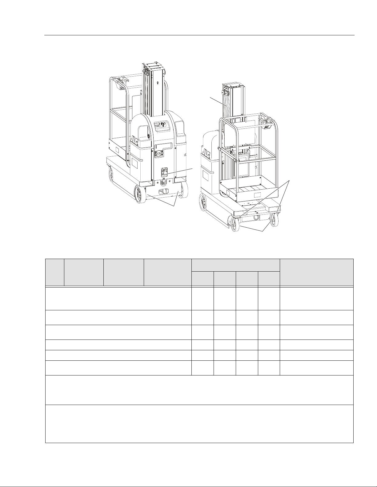
3.1 BASE ASSEMBLY COMPON EN TS . . . . . . . . . . . . . . . . . . . . . . . . . . . . . . . . . . . . . . . . . . . . . . . .3-1
3.2 BASE FR A M E COVERS . . . . . . . . . . . . . . . . . . . . . . . . . . . . . . . . . . . . . . . . . . . . . . . . . . . . . . . . . .3-2
Drive Motor Cover - Installation . . . . . . . . . . . . . . . . . . . . . . . . . . . . . . . . . . . . . . . . . . . . . . .3-2
Battery Charger Cover - Installation . . . . . . . . . . . . . . . . . . . . . . . . . . . . . . . . . . . . . . . . . . .3-2
3.3 DRIVE AN D CASTER WHEELS . . . . . . . . . . . . . . . . . . . . . . . . . . . . . . . . . . . . . . . . . . . . . . . . . . . .3-2
Drive Motor Wheel (Std.) - Installation . . . . . . . . . . . . . . . . . . . . . . . . . . . . . . . . . . . . . . . . . .3-2
Caster Wheels - Installation . . . . . . . . . . . . . . . . . . . . . . . . . . . . . . . . . . . . . . . . . . . . . . . . . .3-2
Wheel Retention for Rough Terrain Drive Wheel (Option) . . . . . . . . . . . . . . . . . . . . . . . . . . .3-3
3.4 DRIVE M O TOR COMPONENT - SERVICING . . . . . . . . . . . . . . . . . . . . . . . . . . . . . . . . . . . . . . . . . .3-3
Torque Limiting Clutch Maintenance . . . . . . . . . . . . . . . . . . . . . . . . . . . . . . . . . . . . . . . . . . .3-3
Diagnostics . . . . . . . . . . . . . . . . . . . . . . . . . . . . . . . . . . . . . . . . . . . . . . . . . . . . . . . . . . . . . . .3-3
Visual Inspection and Limiting Torque Checking Procedure . . . . . . . . . . . . . . . . . . . . . . . . .3-4
Check Clutch Torque Setting . . . . . . . . . . . . . . . . . . . . . . . . . . . . . . . . . . . . . . . . . . . . . . . . .3-4
Torque Limiting Clutch Adjustment. . . . . . . . . . . . . . . . . . . . . . . . . . . . . . . . . . . . . . . . . . . . .3-5
Drive Wheel Alignment - (Machines built prior to S/N-0130005271) . . . . . . . . . . . . . . . . . . .3-5
3.5 DRIVE MOTOR ASSEMBLY - SERVICING. . . . . . . . . . . . . . . . . . . . . . . . . . . . . . . . . . . . . . . . . . . .3-6
Drive Motor Assembly - Removal . . . . . . . . . . . . . . . . . . . . . . . . . . . . . . . . . . . . . . . . . . . . . .3-6
Drive Motor Bra k e Removal and Adjustment . . . . . . . . . . . . . . . . . . . . . . . . . . . . . . . . . . . .3-11
Brake Operation. . . . . . . . . . . . . . . . . . . . . . . . . . . . . . . . . . . . . . . . . . . . . . . . . . . . . . . . . . .3-12
Brake Assembly Removal . . . . . . . . . . . . . . . . . . . . . . . . . . . . . . . . . . . . . . . . . . . . . . . . . . .3-1 2
Checking/Adjusting Armature Plate Gap Se t t ing . . . . . . . . . . . . . . . . . . . . . . . . . . . . . . . . . 3 -12
Brake Assembly Installation . . . . . . . . . . . . . . . . . . . . . . . . . . . . . . . . . . . . . . . . . . . . . . . . .3-13
Drive Motor Boo t As sembly Installation . . . . . . . . . . . . . . . . . . . . . . . . . . . . . . . . . . . . . .3-14
Drive Motor Brush Replacement . . . . . . . . . . . . . . . . . . . . . . . . . . . . . . . . . . . . . . . . . . . . . .3-15
Brush Cleaning and Inspection. . . . . . . . . . . . . . . . . . . . . . . . . . . . . . . . . . . . . . . . . . . . . . .3-15
Brush Removal. . . . . . . . . . . . . . . . . . . . . . . . . . . . . . . . . . . . . . . . . . . . . . . . . . . . . . . . . . . .3-15
Brush Reassembly. . . . . . . . . . . . . . . . . . . . . . . . . . . . . . . . . . . . . . . . . . . . . . . . . . . . . . . . .3-16
Gear Box Disassembly/Assembly. . . . . . . . . . . . . . . . . . . . . . . . . . . . . . . . . . . . . . . . . . . . .3-17
Gear/Pinion Shaft Assembly . . . . . . . . . . . . . . . . . . . . . . . . . . . . . . . . . . . . . . . . . . . . . . . . .3-18
Drive Shaft As s e mbly. . . . . . . . . . . . . . . . . . . . . . . . . . . . . . . . . . . . . . . . . . . . . . . . . . . . . . .3-18
Final Gear Box Assembly . . . . . . . . . . . . . . . . . . . . . . . . . . . . . . . . . . . . . . . . . . . . . . . . . . .3-19
3.6 POT HOLE PROTECTION SYSTEM. . . . . . . . . . . . . . . . . . . . . . . . . . . . . . . . . . . . . . . . . . . . . . . .3-20
3.7 BATTER Y /BATTERY CHARGER - SERVICE PROC E D U RES. . . . . . . . . . . . . . . . . . . . . . . . . . . . 3 -22
Battery Low Volt age Warning Indicators . . . . . . . . . . . . . . . . . . . . . . . . . . . . . . . . . . . . . . . .3-22
Diagnostics . . . . . . . . . . . . . . . . . . . . . . . . . . . . . . . . . . . . . . . . . . . . . . . . . . . . . . . . . . . . . .3-2 2
Battery Condi t i on Testing . . . . . . . . . . . . . . . . . . . . . . . . . . . . . . . . . . . . . . . . . . . . . . . . . . .3-22
ii – JLG Lift – 3121136
Page 7

Battery Replacem e nt . . . . . . . . . . . . . . . . . . . . . . . . . . . . . . . . . . . . . . . . . . . . . . . . . . . . . . .3-23
Battery Charger Ge neral Information . . . . . . . . . . . . . . . . . . . . . . . . . . . . . . . . . . . . . . . . . .3-23
Battery Charger Troubleshooting . . . . . . . . . . . . . . . . . . . . . . . . . . . . . . . . . . . . . . . . . . . . .3-23
Battery Charge/ Fl ash Code LED Indicator on Pla t form Control Console . . . . . . . . . . . . . .3-24
Battery Charging Stat us Indicators Mounted on Ground Control St ation Cover . . . . . . . . .3-24
Wet/VRLA Battery - Charging Profile Switch. . . . . . . . . . . . . . . . . . . . . . . . . . . . . . . . . . . . .3-24
General Component Installation Notes. . . . . . . . . . . . . . . . . . . . . . . . . . . . . . . . . . . . . . . . .3-25
Battery Charger Installation. . . . . . . . . . . . . . . . . . . . . . . . . . . . . . . . . . . . . . . . . . . . . . . . . .3-25
Cover Installa t ion . . . . . . . . . . . . . . . . . . . . . . . . . . . . . . . . . . . . . . . . . . . . . . . . . . . . . . . .3-25
AC Line Fuse Install ation . . . . . . . . . . . . . . . . . . . . . . . . . . . . . . . . . . . . . . . . . . . . . . . . .3-25
Interlock Relay Installation . . . . . . . . . . . . . . . . . . . . . . . . . . . . . . . . . . . . . . . . . . . . . . . .3-26
Wet/VRLA Switch Installation . . . . . . . . . . . . . . . . . . . . . . . . . . . . . . . . . . . . . . . . . . . . . .3-26
Shunt Assembly Installation . . . . . . . . . . . . . . . . . . . . . . . . . . . . . . . . . . . . . . . . . . . . . . .3-26
SCR Rectifier Ins t al la t ion (Either Side) . . . . . . . . . . . . . . . . . . . . . . . . . . . . . . . . . . . . . . . .3-26
Transformer Installation . . . . . . . . . . . . . . . . . . . . . . . . . . . . . . . . . . . . . . . . . . . . . . . . . .3-27
Printed Circuit Board Installation . . . . . . . . . . . . . . . . . . . . . . . . . . . . . . . . . . . . . . . . . . . .3-27
DC Circuit Breaker/Voltage Select Switch Installation . . . . . . . . . . . . . . . . . . . . . . . . . . .3-27
SECTION 4- CONTROL COMPONENTS
4.1 CONTROL COMPONENTS OVERVIEW . . . . . . . . . . . . . . . . . . . . . . . . . . . . . . . . . . . . . . . . . . . .4-1
4.2 CONTROLS COVER INSTALLATION. . . . . . . . . . . . . . . . . . . . . . . . . . . . . . . . . . . . . . . . . . . . . . . .4-2
Battery Cover Doors . . . . . . . . . . . . . . . . . . . . . . . . . . . . . . . . . . . . . . . . . . . . . . . . . . . . . . .4- 2
Center, Left and Rig ht Lo we r Cove rs . . . . . . . . . . . . . . . . . . . . . . . . . . . . . . . . . . . . . . . . . . .4-2
4.3 CONTROL COMPONENTS - INS TAL L A TION . . . . . . . . . . . . . . . . . . . . . . . . . . . . . . . . . . . . . . . . .4-3
Ground Control Module. . . . . . . . . . . . . . . . . . . . . . . . . . . . . . . . . . . . . . . . . . . . . . . . . . . . . .4-3
Traction Control Module . . . . . . . . . . . . . . . . . . . . . . . . . . . . . . . . . . . . . . . . . . . . . . . . . . . . .4-3
Platform Control Console Installati o n . . . . . . . . . . . . . . . . . . . . . . . . . . . . . . . . . . . . . . . . .4-3
Battery Instal l at ion . . . . . . . . . . . . . . . . . . . . . . . . . . . . . . . . . . . . . . . . . . . . . . . . . . . . . . . .4-4
Horn Installation . . . . . . . . . . . . . . . . . . . . . . . . . . . . . . . . . . . . . . . . . . . . . . . . . . . . . . . . . .4-4
Alarm Installation . . . . . . . . . . . . . . . . . . . . . . . . . . . . . . . . . . . . . . . . . . . . . . . . . . . . . . . . .4-4
Battery Instal la t ion (EE Spec Machines Onl y ). . . . . . . . . . . . . . . . . . . . . . . . . . . . . . . . . . . . .4-5
Fuse Box - (EE Spec Machines Only) . . . . . . . . . . . . . . . . . . . . . . . . . . . . . . . . . . . . . . . . .4-5
Master Disconnect Switch - (EE Spec Machines Only) . . . . . . . . . . . . . . . . . . . . . . . . . . . .4-5
4.4 GROUND CONTROL MO DU L E - SERVICE PROCEDURE . . . . . . . . . . . . . . . . . . . . . . . . . . . . . . .4-7
Cover Removal/In s t allation . . . . . . . . . . . . . . . . . . . . . . . . . . . . . . . . . . . . . . . . . . . . . . . . . . .4-8
Power Selector /EStop Switch Installation . . . . . . . . . . . . . . . . . . . . . . . . . . . . . . . . . . . . . .4-9
4.5 GROUND CONTROL MO DU L E - PROGR AM M IN G. . . . . . . . . . . . . . . . . . . . . . . . . . . . . . . . . . . .4-10
General. . . . . . . . . . . . . . . . . . . . . . . . . . . . . . . . . . . . . . . . . . . . . . . . . . . . . . . . . . . . . . . . . .4-10
Programming Le v e l s . . . . . . . . . . . . . . . . . . . . . . . . . . . . . . . . . . . . . . . . . . . . . . . . . . . . . . .4-10
Activating Programming Mode . . . . . . . . . . . . . . . . . . . . . . . . . . . . . . . . . . . . . . . . . . . . . .4-10
Entering Password . . . . . . . . . . . . . . . . . . . . . . . . . . . . . . . . . . . . . . . . . . . . . . . . . . . . . . .4-11
Programming Mode Selection . . . . . . . . . . . . . . . . . . . . . . . . . . . . . . . . . . . . . . . . . . . . . .4-11
Selecting Programmable Item to Adjust . . . . . . . . . . . . . . . . . . . . . . . . . . . . . . . . . . . . . . .4-11
Adjusting Programmable Setting . . . . . . . . . . . . . . . . . . . . . . . . . . . . . . . . . . . . . . . . . . .4-11
Service Programming Mode - (Level-2 ) . . . . . . . . . . . . . . . . . . . . . . . . . . . . . . . . . . . . . . . .4-12
Operator Programming Mode - (Level-3) . . . . . . . . . . . . . . . . . . . . . . . . . . . . . . . . . . . . . . .4-12
4.6 PLATFORM CONTROL CONSOLE - SERVICE PROCEDURES -
(MACHINES S/N - 0130007616 TO PRESENT) . . . . . . . . . . . . . . . . . . . . . . . . . . . . . . . . . . . . . .4-14
General. . . . . . . . . . . . . . . . . . . . . . . . . . . . . . . . . . . . . . . . . . . . . . . . . . . . . . . . . . . . . . . . . .4-14
Remove Platform Control Console . . . . . . . . . . . . . . . . . . . . . . . . . . . . . . . . . . . . . . . . . . . .4-14
Display/Controller Module Electrical Connectio ns . . . . . . . . . . . . . . . . . . . . . . . . . . . . . . . .4-15
Mounting Bracke t - Inst all/Remove . . . . . . . . . . . . . . . . . . . . . . . . . . . . . . . . . . . . . . . . . .4-15
Rear Cover - Install/Remove . . . . . . . . . . . . . . . . . . . . . . . . . . . . . . . . . . . . . . . . . . . . . . .4-15
Display/Cont roller Module - Inst al l /Remove . . . . . . . . . . . . . . . . . . . . . . . . . . . . . . . . . . . . .4-16
Drive/Lift Mod e Switch - Install/R e move . . . . . . . . . . . . . . . . . . . . . . . . . . . . . . . . . . . . . . .4-16
Horn Button Switc h - Install/Remove . . . . . . . . . . . . . . . . . . . . . . . . . . . . . . . . . . . . . . . . . .4-16
TABLE OF CONTENTS
3121136 – JLG Lift – iii
Page 8

TABLE OF CONTENTS
Key Switch - Install/Remove . . . . . . . . . . . . . . . . . . . . . . . . . . . . . . . . . . . . . . . . . . . . . . . .4-16
E-Stop/Shut D own Switch - Install/Remove . . . . . . . . . . . . . . . . . . . . . . . . . . . . . . . . . . . 4 -17
Joystick Assembly - Install/Remove . . . . . . . . . . . . . . . . . . . . . . . . . . . . . . . . . . . . . . . . . .4- 1 7
4.7 PLATFORM CONTROL CONSOLE - SERVICE PROCEDURES -
(MACHINES PRIOR TO S/N - 0130007616) . . . . . . . . . . . . . . . . . . . . . . . . . . . . . . . . . . . . . . . . .4-18
General . . . . . . . . . . . . . . . . . . . . . . . . . . . . . . . . . . . . . . . . . . . . . . . . . . . . . . . . . . . . . . . . .4-18
Remove Platform Control Console . . . . . . . . . . . . . . . . . . . . . . . . . . . . . . . . . . . . . . . . . . . .4-18
Upper/Lower Shell Attach Screws . . . . . . . . . . . . . . . . . . . . . . . . . . . . . . . . . . . . . . . . . . .4-19
Emergency Sto p Switch Installation . . . . . . . . . . . . . . . . . . . . . . . . . . . . . . . . . . . . . . . . . . 4 -19
Upper/Lower Sh ell Component Connections . . . . . . . . . . . . . . . . . . . . . . . . . . . . . . . . . . . .4-19
Button Pad Installation . . . . . . . . . . . . . . . . . . . . . . . . . . . . . . . . . . . . . . . . . . . . . . . . . . . . .4-19
Joystick Assembly Installation . . . . . . . . . . . . . . . . . . . . . . . . . . . . . . . . . . . . . . . . . . . . . . .4-20
Joystick Calibration Procedure . . . . . . . . . . . . . . . . . . . . . . . . . . . . . . . . . . . . . . . . . . . . . . .4-20
4.8 PUMP-M OT O R ASSEMBLY - SERVICE PROCEDURE . . . . . . . . . . . . . . . . . . . . . . . . . . . . . . . . .4-21
General . . . . . . . . . . . . . . . . . . . . . . . . . . . . . . . . . . . . . . . . . . . . . . . . . . . . . . . . . . . . . . . . .4-21
Inline Hydraulic Filter Installation . . . . . . . . . . . . . . . . . . . . . . . . . . . . . . . . . . . . . . . . . . . .4-21
Pump/Motor/Tank Installation . . . . . . . . . . . . . . . . . . . . . . . . . . . . . . . . . . . . . . . . . . . . . . . .4-21
Motor Cap/Motor I nstallation . . . . . . . . . . . . . . . . . . . . . . . . . . . . . . . . . . . . . . . . . . . . . . .4-22
Motor Brush Ins t allation . . . . . . . . . . . . . . . . . . . . . . . . . . . . . . . . . . . . . . . . . . . . . . . . . . .4-22
Brush Housin g F inal Assembly Tips . . . . . . . . . . . . . . . . . . . . . . . . . . . . . . . . . . . . . . . . . . .4- 2 3
Tank Installation . . . . . . . . . . . . . . . . . . . . . . . . . . . . . . . . . . . . . . . . . . . . . . . . . . . . . . . .4-24
Pump Installati on . . . . . . . . . . . . . . . . . . . . . . . . . . . . . . . . . . . . . . . . . . . . . . . . . . . . . . .4- 2 4
Filter Screen Installation . . . . . . . . . . . . . . . . . . . . . . . . . . . . . . . . . . . . . . . . . . . . . . . . . .4-24
Pressure Adjust V al v e Installation . . . . . . . . . . . . . . . . . . . . . . . . . . . . . . . . . . . . . . . . . . .4-25
Pressure Check Valve Installation . . . . . . . . . . . . . . . . . . . . . . . . . . . . . . . . . . . . . . . . . . .4-25
4.9 OBSTRU CTION SENSOR SYSTEM - SERVICE P RO CEDURE (DVSP - OPTION) . . . . . . . . . . . .4-2 6
General . . . . . . . . . . . . . . . . . . . . . . . . . . . . . . . . . . . . . . . . . . . . . . . . . . . . . . . . . . . . . . . . .4-26
Transducer Sensor Check. . . . . . . . . . . . . . . . . . . . . . . . . . . . . . . . . . . . . . . . . . . . . . . . . . .4-27
OSS Component Installation. . . . . . . . . . . . . . . . . . . . . . . . . . . . . . . . . . . . . . . . . . . . . . . . .4-28
SECTION 5 - MAST COMPONENTS
5.1 MAST COMPONENTS OVER VI EW . . . . . . . . . . . . . . . . . . . . . . . . . . . . . . . . . . . . . . . . . . . . . . . .5-1
5.2 MAST CHAINS AND SEQUENCING CABLES ADJUSTMENT . . . . . . . . . . . . . . . . . . . . . . . . . . . . 5-2
Mast Chain/Cable Adjustment . . . . . . . . . . . . . . . . . . . . . . . . . . . . . . . . . . . . . . . . . . . . . . . . .5-2
Sequencing Cab l e Adj us t ment . . . . . . . . . . . . . . . . . . . . . . . . . . . . . . . . . . . . . . . . . . . . . . . .5-2
5.3 SEQUENCE CABLE REPLACEMENT KIT . . . . . . . . . . . . . . . . . . . . . . . . . . . . . . . . . . . . . . . . . . . .5-4
Remove Old Cable. . . . . . . . . . . . . . . . . . . . . . . . . . . . . . . . . . . . . . . . . . . . . . . . . . . . . . . . . .5-4
Replacement Ca bl e Installation. . . . . . . . . . . . . . . . . . . . . . . . . . . . . . . . . . . . . . . . . . . . . . . .5-4
Clamp Installat i on (Drum/Socket Type) . . . . . . . . . . . . . . . . . . . . . . . . . . . . . . . . . . . . . . . . .5-4
5.4 HYDRAUL IC LIFT CYLINDER - REMOVAL , IN SPECTION AND REBUILD . . . . . . . . . . . . . . . . . . .5-7
Lift Cylinder Re moval. . . . . . . . . . . . . . . . . . . . . . . . . . . . . . . . . . . . . . . . . . . . . . . . . . . . . . . .5-7
Cylinder Disa s s e mbly . . . . . . . . . . . . . . . . . . . . . . . . . . . . . . . . . . . . . . . . . . . . . . . . . . . . . . .5-9
Lift Cylinder Component Inspection . . . . . . . . . . . . . . . . . . . . . . . . . . . . . . . . . . . . . . . . . . . .5-9
Cylinder Assembly. . . . . . . . . . . . . . . . . . . . . . . . . . . . . . . . . . . . . . . . . . . . . . . . . . . . . . . . .5-10
Cylinder Insta l lation. . . . . . . . . . . . . . . . . . . . . . . . . . . . . . . . . . . . . . . . . . . . . . . . . . . . . . . .5-11
5.5 MAST ASSEMBLY INSTALLATION . . . . . . . . . . . . . . . . . . . . . . . . . . . . . . . . . . . . . . . . . . . . . . . .5-12
Mast Removal . . . . . . . . . . . . . . . . . . . . . . . . . . . . . . . . . . . . . . . . . . . . . . . . . . . . . . . . . . . .5-12
Mast Installation. . . . . . . . . . . . . . . . . . . . . . . . . . . . . . . . . . . . . . . . . . . . . . . . . . . . . . . . . . .5-12
5.6 MAST A SSE M BLY AND DISASSEMBLY PROC ED URES . . . . . . . . . . . . . . . . . . . . . . . . . . . . . . .5-13
Mast Disassembly Procedure . . . . . . . . . . . . . . . . . . . . . . . . . . . . . . . . . . . . . . . . . . . . . . . .5-13
Mast Assembly - DVL/DVSP . . . . . . . . . . . . . . . . . . . . . . . . . . . . . . . . . . . . . . . . . . . . . . . . .5-16
5.7 DVSP - STOCKPICKER PLATFORM - INSTALL A TION . . . . . . . . . . . . . . . . . . . . . . . . . . . . . . . . . 5 -24
5.8 DVSP - STOCKPICKER PLATFORM - MID-GATE I N T ER L O CK INSTALLATION. . . . . . . . . . . . . .5-25
5.9 MAST BEACON - INSTALLATION . . . . . . . . . . . . . . . . . . . . . . . . . . . . . . . . . . . . . . . . . . . . . . . .5-25
iv – JLG Lift – 3121136
Page 9

SECTION 6- TROUBLESHOOTING
6.1 GENER AL. . . . . . . . . . . . . . . . . . . . . . . . . . . . . . . . . . . . . . . . . . . . . . . . . . . . . . . . . . . . . . . . . . . . .6-1
6.2 TROUBLESHOOTING INFORMATION. . . . . . . . . . . . . . . . . . . . . . . . . . . . . . . . . . . . . . . . . . . . . . .6-1
6.3 HYDRAULIC CIRCUIT CHECKS. . . . . . . . . . . . . . . . . . . . . . . . . . . . . . . . . . . . . . . . . . . . . . . . . . . .6-1
6.4 ELECTRICAL CIRCUIT CHECKS. . . . . . . . . . . . . . . . . . . . . . . . . . . . . . . . . . . . . . . . . . . . . . . . . . .6-1
General. . . . . . . . . . . . . . . . . . . . . . . . . . . . . . . . . . . . . . . . . . . . . . . . . . . . . . . . . . . . . . . . . . .6-1
Ground Control Module LCD Display . . . . . . . . . . . . . . . . . . . . . . . . . . . . . . . . . . . . . . . . . . .6-2
6.5 TROUBLESHOOTING TABLES INDEX . . . . . . . . . . . . . . . . . . . . . . . . . . . . . . . . . . . . . . . . . . . . . .6-8
Specifications For Various Components. . . . . . . . . . . . . . . . . . . . . . . . . . . . . . . . . . . . . . . . .6-8
Special Pin Extract or Tools F or Ele c t r ic al Connectors. . . . . . . . . . . . . . . . . . . . . . . . . . . . . .6-8
Fault Code Troub le s hooting Tables . . . . . . . . . . . . . . . . . . . . . . . . . . . . . . . . . . . . . . . . . . . .6-8
Main Power Circuit Troubleshooting. . . . . . . . . . . . . . . . . . . . . . . . . . . . . . . . . . . . . . . . . . . .6-9
Mast Troubleshooting . . . . . . . . . . . . . . . . . . . . . . . . . . . . . . . . . . . . . . . . . . . . . . . . . . . . . . .6-9
Hydraulic Leak Troubleshooting . . . . . . . . . . . . . . . . . . . . . . . . . . . . . . . . . . . . . . . . . . . . . . .6-9
Base Frame Components Troubleshooting . . . . . . . . . . . . . . . . . . . . . . . . . . . . . . . . . . . . . .6-9
Drive System Troubleshooting . . . . . . . . . . . . . . . . . . . . . . . . . . . . . . . . . . . . . . . . . . . . . . . .6-9
6.6 SPECIFICATION S FOR VARIOUS COM PONENTS. . . . . . . . . . . . . . . . . . . . . . . . . . . . . . . . . . . .6-10
6.7 SPECIAL PIN EXTRACTOR TOOL S FOR ELECTRICAL CONNECTORS . . . . . . . . . . . . . . . . . . .6-10
6.8 FAULT CODE TROUBLESH OOTI N G TABL ES . . . . . . . . . . . . . . . . . . . . . . . . . . . . . . . . . . . . . . .6-11
Machine in Drive Spee d Cut- Back (Turtle) Mode All The Tim e . . . . . . . . . . . . . . . . . . . . . .6-11
Obstruction Sensor System - Detectio n . . . . . . . . . . . . . . . . . . . . . . . . . . . . . . . . . . . . . . . .6-12
Battery Voltage Low - Warning Level 3 - Three (3) LED/LCDs lit. . . . . . . . . . . . . . . . . . . . .6-12
Code 02 - Left PHP Bar - UP. . . . . . . . . . . . . . . . . . . . . . . . . . . . . . . . . . . . . . . . . . . . . . . . .6-13
Code 03 - Right PHP Bar - UP . . . . . . . . . . . . . . . . . . . . . . . . . . . . . . . . . . . . . . . . . . . . . . .6-13
Code 04 - Tilt Condit ion . . . . . . . . . . . . . . . . . . . . . . . . . . . . . . . . . . . . . . . . . . . . . . . . . . . .6-14
Code 05 - Reserved . . . . . . . . . . . . . . . . . . . . . . . . . . . . . . . . . . . . . . . . . . . . . . . . . . . . . . .6-14
Code 06 - Reserved . . . . . . . . . . . . . . . . . . . . . . . . . . . . . . . . . . . . . . . . . . . . . . . . . . . . . . .6-14
Code 07- Left Drive Mo t or - D is c onnected. . . . . . . . . . . . . . . . . . . . . . . . . . . . . . . . . . . . . .6-14
Code 08 - Right Drive Mot o r - D is connected . . . . . . . . . . . . . . . . . . . . . . . . . . . . . . . . . . . .6-15
Code 09 - Left Brake - Dis co n nected. . . . . . . . . . . . . . . . . . . . . . . . . . . . . . . . . . . . . . . . . .6-15
Code 10 - Right Brake - Dis connected. . . . . . . . . . . . . . . . . . . . . . . . . . . . . . . . . . . . . . . . .6-15
Code 11 - Left Drive Motor - Shor t Circ uit . . . . . . . . . . . . . . . . . . . . . . . . . . . . . . . . . . . . . .6-16
Code 12 - Right Drive Motor - Sh ort Circuit . . . . . . . . . . . . . . . . . . . . . . . . . . . . . . . . . . . . .6-16
Code 13 - Traction Mod ul e - In Fol d Back . . . . . . . . . . . . . . . . . . . . . . . . . . . . . . . . . . . . . .6-16
Code 14 - Pump Motor - Dis connected . . . . . . . . . . . . . . . . . . . . . . . . . . . . . . . . . . . . . . . .6-17
Code 15 - Lift Down Val v e - Disc onnected. . . . . . . . . . . . . . . . . . . . . . . . . . . . . . . . . . . . . .6-17
Code 16 - Lift Down Val v e - Sho r t Circ uit. . . . . . . . . . . . . . . . . . . . . . . . . . . . . . . . . . . . . . .6-18
Code 17 - Ground Cont rol M odule - In Fold Back. . . . . . . . . . . . . . . . . . . . . . . . . . . . . . . .6-18
Code 18 - Alarm - Short Circuit. . . . . . . . . . . . . . . . . . . . . . . . . . . . . . . . . . . . . . . . . . . . . . .6-18
Code 19 - Alarm - Disconnected . . . . . . . . . . . . . . . . . . . . . . . . . . . . . . . . . . . . . . . . . . . . .6-19
Code 20 - Beacon - Short Circuit . . . . . . . . . . . . . . . . . . . . . . . . . . . . . . . . . . . . . . . . . . . . .6-19
Code 21 - Beacon - Disc onnected. . . . . . . . . . . . . . . . . . . . . . . . . . . . . . . . . . . . . . . . . . . .6-20
Code 22 - Horn - Short Circuit . . . . . . . . . . . . . . . . . . . . . . . . . . . . . . . . . . . . . . . . . . . . . . .6-20
Code 23 - Horn - Disconnected . . . . . . . . . . . . . . . . . . . . . . . . . . . . . . . . . . . . . . . . . . . . . .6-21
Code 24 - Auxiliary #1 Circui t - Sh ort Circuit. . . . . . . . . . . . . . . . . . . . . . . . . . . . . . . . . . . .6-21
Code 25 - Auxiliary #1 Circu it - Di s co n nected. . . . . . . . . . . . . . . . . . . . . . . . . . . . . . . . . . .6-22
Code 26 - Auxiliary #2 - Sh ort Circuit. . . . . . . . . . . . . . . . . . . . . . . . . . . . . . . . . . . . . . . . . .6-22
Code 27 - Auxiliary #2 - Dis connected . . . . . . . . . . . . . . . . . . . . . . . . . . . . . . . . . . . . . . . .6-23
Code 28 - Reserved . . . . . . . . . . . . . . . . . . . . . . . . . . . . . . . . . . . . . . . . . . . . . . . . . . . . . . .6-23
Code 29 - Reserved . . . . . . . . . . . . . . . . . . . . . . . . . . . . . . . . . . . . . . . . . . . . . . . . . . . . . . .6-23
Code 30 - Traction Mod ul e - No Com m unication with Ground Control Module. . . . . . . . .6-24
Code 31 - Platform Control Con sol e - No Communication with Ground Control Module .6-25
Code 32 - Pump Motor - Over Current . . . . . . . . . . . . . . . . . . . . . . . . . . . . . . . . . . . . . . . . .6-25
Code 33 - Both PHP Bars - UP. . . . . . . . . . . . . . . . . . . . . . . . . . . . . . . . . . . . . . . . . . . . . . .6-26
Code 38 - Battery Volt age Low - Warning Level 2 - Two (2 ) LED/LCDs lit . . . . . . . . . . . . .6-26
TABLE OF CONTENTS
3121136 – JLG Lift – v
Page 10

TABLE OF CONTENTS
Code 39 - Battery Vo l t age Low - Warning Level 3 - One (1) LED/LCDs lit . . . . . . . . . . . . .6-26
Code 40 - Obstruction Sensor System - No Communication with Ground Control Module6-27
Codes 41 thru 46 - OSS - Se nsor 1 through 6 - Fault Conditi on . . . . . . . . . . . . . . . . . . . . .6-28
Codes (100 - 199) Ground Control Module - Fault Condition . . . . . . . . . . . . . . . . . . . . . . .6-29
Codes (200 - 299) Platform Control Console - Fault Condition. . . . . . . . . . . . . . . . . . . . . .6-30
Codes (300 - 399) Traction Control Module - Fault Condition. . . . . . . . . . . . . . . . . . . . . . .6-31
6.9 MAIN POW E R CIRCUIT TROUBLESHOOTING. . . . . . . . . . . . . . . . . . . . . . . . . . . . . . . . . . . . . . .6-32
Machine Will Not Power Up. . . . . . . . . . . . . . . . . . . . . . . . . . . . . . . . . . . . . . . . . . . . . . . . . .6-32
6.10 M AST TROUBLESHOOTING . . . . . . . . . . . . . . . . . . . . . . . . . . . . . . . . . . . . . . . . . . . . . . . . . . . . .6-33
Platform Will Not Lower Manually . . . . . . . . . . . . . . . . . . . . . . . . . . . . . . . . . . . . . . . . . . . . .6-33
Platform Lift Up And Down Jerky . . . . . . . . . . . . . . . . . . . . . . . . . . . . . . . . . . . . . . . . . . . . .6-33
Mast Noisy When L if t ing And Lowering . . . . . . . . . . . . . . . . . . . . . . . . . . . . . . . . . . . . . . . .6-34
Platform (Mast ) Wo n’t Stay Elevated. . . . . . . . . . . . . . . . . . . . . . . . . . . . . . . . . . . . . . . . . . .6-35
Platform (Mast ) Descends Too Slowly . . . . . . . . . . . . . . . . . . . . . . . . . . . . . . . . . . . . . . . . .6-35
6.11 H Y D RAULIC LEAK TROUBLESHOO TING. . . . . . . . . . . . . . . . . . . . . . . . . . . . . . . . . . . . . . . . . . .6-36
Miscellaneous Hydraulic Leak Troubles hooting. . . . . . . . . . . . . . . . . . . . . . . . . . . . . . . . . .6-36
6.12 B A SE FRAME COMPONENTS TROUBL ESHOOTING . . . . . . . . . . . . . . . . . . . . . . . . . . . . . . . . .6-37
Caster Wheels No t Operating Freely. . . . . . . . . . . . . . . . . . . . . . . . . . . . . . . . . . . . . . . . . . .6-37
Pot Hole Protecti on (PHP) Bars will not Lower . . . . . . . . . . . . . . . . . . . . . . . . . . . . . . . . . . .6-37
6.13 DRIVE SYSTEM TROUBLESHOOTING. . . . . . . . . . . . . . . . . . . . . . . . . . . . . . . . . . . . . . . . . . . . .6-38
Won’t Climb Grade . . . . . . . . . . . . . . . . . . . . . . . . . . . . . . . . . . . . . . . . . . . . . . . . . . . . . . . .6-38
Machine Drive s in Opposite Direction. . . . . . . . . . . . . . . . . . . . . . . . . . . . . . . . . . . . . . . . . .6-3 9
Machine Won’t Drive Straight . . . . . . . . . . . . . . . . . . . . . . . . . . . . . . . . . . . . . . . . . . . . . . . .6-40
Noise From Drive Assembly . . . . . . . . . . . . . . . . . . . . . . . . . . . . . . . . . . . . . . . . . . . . . . . . .6-41
vi – JLG Lift – 3121136
Page 11

TABLE OF CONTENTS
LIST OF FIGURES
FIGURE NO. TITLE PAGE NO.
1-1. Hydraulic Pressure Adjustment Screw . (M achine Rear Covers Removed) . . . . . . . . . . . . . . . . . .1-3
1-2. Typical Hydraulic Pres s ure Gaug e In stallation (Hydraulic Filter Removed).. . . . . . . . . . . . . . . . .1-4
1-3. Typical Hydraulic Pre s s ure Gaug e Installation (After Hydraulic Filter).. . . . . . . . . . . . . . . . . . . . .1-4
1-4. Torque Chart. (ANSI Spec.) . . . . . . . . . . . . . . . . . . . . . . . . . . . . . . . . . . . . . . . . . . . . . . . . . . . . . .1-6
1-5. Torque Chart. (ANSI t o M E TRI C Conversion) . . . . . . . . . . . . . . . . . . . . . . . . . . . . . . . . . . . . . . . .1-7
1-6. Torque Chart (Metric Class Fasteners) . . . . . . . . . . . . . . . . . . . . . . . . . . . . . . . . . . . . . . . . . . . . . .1-8
2-1. Accessing Machin e Un de rs id e Components by Liftin g wit h a Fork Truc k.. . . . . . . . . . . . . . . . . .2-9
3-1. Base Components . . . . . . . . . . . . . . . . . . . . . . . . . . . . . . . . . . . . . . . . . . . . . . . . . . . . . . . . . . . . . .3-1
3-2. Drive Motor Assembly Components. (Mach ines built prior to S/N-0130005271). . . . . . . . . . . . .3-7
3-3. Drive Motor Assembly Components. (Mach ines built since S/N-0130005271) . . . . . . . . . . . . . .3-7
3-4. Drive Motor Component Assembly (Mach i nes bui lt prior to S/N-0130005271) . . . . . . . . . . . . . .3-9
3-5. Drive Motor Component Assembly (Mach i nes bui lt since S/N-0130005271). . . . . . . . . . . . . . . .3-10
3-6. Torque Limiting Clutch Assembly. . . . . . . . . . . . . . . . . . . . . . . . . . . . . . . . . . . . . . . . . . . . . . . . . .3-11
3-7. Brake Assembly Com ponents . . . . . . . . . . . . . . . . . . . . . . . . . . . . . . . . . . . . . . . . . . . . . . . . . . . .3-12
3-8. Drive Motor Gear Box Assem bly - DV L /D VSP. . . . . . . . . . . . . . . . . . . . . . . . . . . . . . . . . . . . . . . . .3-17
3-9. Pot-Hole-Prote c t ion Sys t e m Com ponents.. . . . . . . . . . . . . . . . . . . . . . . . . . . . . . . . . . . . . . . . . . .3-20
3-10. DVL/DVSP - SCR Dual Voltage - Battery Charger Wiring Diagram.. . . . . . . . . . . . . . . . . . . . . . . .3-28
4-1. Control Components Location - DVL/DVSP. . . . . . . . . . . . . . . . . . . . . . . . . . . . . . . . . . . . . . . . . .4-1
4-2. Component Electrical Connections.. . . . . . . . . . . . . . . . . . . . . . . . . . . . . . . . . . . . . . . . . . . . . . . .4-6
4-3. Ground Control Module Components.. . . . . . . . . . . . . . . . . . . . . . . . . . . . . . . . . . . . . . . . . . . . . .4-7
4-4. Platform Control Console Component s.. . . . . . . . . . . . . . . . . . . . . . . . . . . . . . . . . . . . . . . . . . . . .4-14
4-5. Platform Control Console Component s.. . . . . . . . . . . . . . . . . . . . . . . . . . . . . . . . . . . . . . . . . . . . .4-18
5-1. Mast Component s . (D VL/DVSP) . . . . . . . . . . . . . . . . . . . . . . . . . . . . . . . . . . . . . . . . . . . . . . . . . . .5-1
5-2. DVL/DVSP - Mast Chain and Sequence Cable Adjustment Com ponents. . . . . . . . . . . . . . . . . . .5-3
5-3. Machine Positio ne d fo r Cy l inder Re m ov al.. . . . . . . . . . . . . . . . . . . . . . . . . . . . . . . . . . . . . . . . . . .5-7
5-4. Lift Cylinder Component Cross-Section (DVL/DVSP ) . . . . . . . . . . . . . . . . . . . . . . . . . . . . . . . . . . .5-10
5-5. Mast Section - Assembly Reference. . . . . . . . . . . . . . . . . . . . . . . . . . . . . . . . . . . . . . . . . . . . . . . .5-13
5-6. Mast Chain Routin g D iagram. - DVL/DVSP. . . . . . . . . . . . . . . . . . . . . . . . . . . . . . . . . . . . . . . . . . .5-15
5-7. Mast Bottom End - Slid e Pa d Installation (Typical) . . . . . . . . . . . . . . . . . . . . . . . . . . . . . . . . . . . .5-16
5-8. Mast Top End - Slide Pa d Installation (Typical) . . . . . . . . . . . . . . . . . . . . . . . . . . . . . . . . . . . . . . .5-17
5-9. DVSP - StockPicker Plat form Ins t all ation.. . . . . . . . . . . . . . . . . . . . . . . . . . . . . . . . . . . . . . . . . . . .5-24
6-1. Component Electrical Connections.. . . . . . . . . . . . . . . . . . . . . . . . . . . . . . . . . . . . . . . . . . . . . . . .6-3
6-2. Overview of Electr ic al Sys t e m Components. (DVL /D VSP) (Sheet 1 of 2) . . . . . . . . . . . . . . . . . . .6-42
6-3. Electrical Diagram . (DVL/DVSP) (Sheet 1) . . . . . . . . . . . . . . . . . . . . . . . . . . . . . . . . . . . . . . . . . . . 6 -44
6-4. Electrical Diagram - (with Load Sensing System) (DVL/DVSP ) (S hee t 2 ) . . . . . . . . . . . . . . . . . . .6-46
6-5. Hydraulic Diagram . ( D VL /DVSP). . . . . . . . . . . . . . . . . . . . . . . . . . . . . . . . . . . . . . . . . . . . . . . . . . .6-48
LIST OF TABLES
TABLE NO. TITLE PAGE NO.
1-1 DVL and DVSP - Machine Specifications . . . . . . . . . . . . . . . . . . . . . . . . . . . . . . . . . . . . . . . . . . . .1-1
1-2 Hydraulic Oil Operat ing Rang e. . . . . . . . . . . . . . . . . . . . . . . . . . . . . . . . . . . . . . . . . . . . . . . . . . . .1-3
1-3. Lubrication Specifications. . . . . . . . . . . . . . . . . . . . . . . . . . . . . . . . . . . . . . . . . . . . . . . . . . . . . . . .1-3
1-4. Cylinder Speci f ic at ions . . . . . . . . . . . . . . . . . . . . . . . . . . . . . . . . . . . . . . . . . . . . . . . . . . . . . . . . . .1-4
1-5 Lubrication Interv al s for Vario us Components . . . . . . . . . . . . . . . . . . . . . . . . . . . . . . . . . . . . . . . .1-5
2-1 Inspection and Mai nt e nance. . . . . . . . . . . . . . . . . . . . . . . . . . . . . . . . . . . . . . . . . . . . . . . . . . . . . .2-2
2-2 DVL/DVSP - Preventive Maintenance & Inspection Schedule.. . . . . . . . . . . . . . . . . . . . . . . . . . . .2-4
2-3 Chain Stretch Tolera nce . . . . . . . . . . . . . . . . . . . . . . . . . . . . . . . . . . . . . . . . . . . . . . . . . . . . . . . . .2-7
3-1 Battery Low Voltage Warning Indicators. . . . . . . . . . . . . . . . . . . . . . . . . . . . . . . . . . . . . . . . . . . . .3-22
4-1 DVL/DVSP Ground Control Module - Field Programmable Settings and Factory Preset.. . . . . . .4-13
4-2 Obstruction Se ns or Sys tem Components (Platform Cutawa y ) . . . . . . . . . . . . . . . . . . . . . . . . . . .4-26
5-1 DVL/DVSP Mast Component Features. . . . . . . . . . . . . . . . . . . . . . . . . . . . . . . . . . . . . . . . . . . . . .5-13
6-1 LCD Display - Service Fault Code Conditions. . . . . . . . . . . . . . . . . . . . . . . . . . . . . . . . . . . . . . . .6-4
3121136 – JLG Lift – vii
Page 12

TABLE OF CONTENTS
6-2 Ohm Ratings for Various Components. . . . . . . . . . . . . . . . . . . . . . . . . . . . . . . . . . . . . . . . . . . . . .6-10
6-3 Amper age Draw for Various Components . . . . . . . . . . . . . . . . . . . . . . . . . . . . . . . . . . . . . . . . . . .6-10
6-4 Speci a l Pin Extractor Tools for Elect rical Connectors . . . . . . . . . . . . . . . . . . . . . . . . . . . . . . . . . .6-10
6-5 Machine In Drive Speed Cut-Back (Turtle) Mode All The Time . . . . . . . . . . . . . . . . . . . . . . . . . . .6-11
6-6 Obstr uction Sensor System - Detection. . . . . . . . . . . . . . . . . . . . . . . . . . . . . . . . . . . . . . . . . . . . .6-12
6-7 Code 02 - L e f t PH P Bar - UP . . . . . . . . . . . . . . . . . . . . . . . . . . . . . . . . . . . . . . . . . . . . . . . . . . . . . .6-13
6-8 Code 03 - Right PHP Bar - UP. . . . . . . . . . . . . . . . . . . . . . . . . . . . . . . . . . . . . . . . . . . . . . . . . . . . .6-13
6-9 Code 04 - T il t Condition . . . . . . . . . . . . . . . . . . . . . . . . . . . . . . . . . . . . . . . . . . . . . . . . . . . . . . . . .6-14
6-10 Code 07 - Left Dri v e Mo t or - Disconnected . . . . . . . . . . . . . . . . . . . . . . . . . . . . . . . . . . . . . . . . . .6-14
6-11 Code 08 - Right Dr iv e M otor Disconnected . . . . . . . . . . . . . . . . . . . . . . . . . . . . . . . . . . . . . . . . . .6-15
6-12 Code 0 9 - Left Brake - Disconnected . . . . . . . . . . . . . . . . . . . . . . . . . . . . . . . . . . . . . . . . . . . . . . .6-15
6-13 Code 10 - Right Brake - Disconnected. . . . . . . . . . . . . . . . . . . . . . . . . . . . . . . . . . . . . . . . . . . . . .6-15
6-14 Code 11 - Left Dri v e Mot or - Short Circuit. . . . . . . . . . . . . . . . . . . . . . . . . . . . . . . . . . . . . . . . . . . .6-16
6-15 Code 12 - Right Dr iv e M otor - Short Circuit . . . . . . . . . . . . . . . . . . . . . . . . . . . . . . . . . . . . . . . . . .6-16
6-16 Code 13 - Tractio n M odule - In Fold Back . . . . . . . . . . . . . . . . . . . . . . . . . . . . . . . . . . . . . . . . . . .6-16
6-17 Code 14 - Pump Motor - Disconnected . . . . . . . . . . . . . . . . . . . . . . . . . . . . . . . . . . . . . . . . . . . . .6-17
6-18 Code 15 - Lift Dow n V al v e - D is connected. . . . . . . . . . . . . . . . . . . . . . . . . . . . . . . . . . . . . . . . . . .6-17
6-19 Code 16 - Lift Down Valve - Short Circuit . . . . . . . . . . . . . . . . . . . . . . . . . . . . . . . . . . . . . . . . . . . .6-18
6-20 Code 17 - Ground Co nt r ol Module - In Fold Back . . . . . . . . . . . . . . . . . . . . . . . . . . . . . . . . . . . . .6-18
6-21 Code 18 - Alarm - Short Circuit. . . . . . . . . . . . . . . . . . . . . . . . . . . . . . . . . . . . . . . . . . . . . . . . . . . .6-18
6-22 Code 19 - Alarm - Disconnected. . . . . . . . . . . . . . . . . . . . . . . . . . . . . . . . . . . . . . . . . . . . . . . . . . .6-19
6-23 Code 20 - Beacon - Short Circuit . . . . . . . . . . . . . . . . . . . . . . . . . . . . . . . . . . . . . . . . . . . . . . . . . .6-19
6-24 Code 21 - Beacon - Sh or t D isconnected . . . . . . . . . . . . . . . . . . . . . . . . . . . . . . . . . . . . . . . . . . . .6 -20
6-25 Code 2 2 - Horn - Short Circuit . . . . . . . . . . . . . . . . . . . . . . . . . . . . . . . . . . . . . . . . . . . . . . . . . . . .6- 20
6-26 Code 23 - Horn - Disconnected . . . . . . . . . . . . . . . . . . . . . . . . . . . . . . . . . . . . . . . . . . . . . . . . . . .6-21
6-27 Code 24 - Auxil iary #1 Circuit - Short Circuit . . . . . . . . . . . . . . . . . . . . . . . . . . . . . . . . . . . . . . . . .6-21
6-28 Code 25 - Auxil ia ry #1 Circuit - Disconnected . . . . . . . . . . . . . . . . . . . . . . . . . . . . . . . . . . . . . . . .6-22
6-29 Code 2 6 - Auxil iary #2 - Short Circuit. . . . . . . . . . . . . . . . . . . . . . . . . . . . . . . . . . . . . . . . . . . . . . . 6-22
6-30 Code 2 7 - Auxil iary #2 - Disconnected. . . . . . . . . . . . . . . . . . . . . . . . . . . . . . . . . . . . . . . . . . . . . .6-23
6-31 Code 30 - Tractio n Module - No Communication with Grou nd Control Module . . . . . . . . . . . . . .6-24
6-32 Code 31 - Platfor m Control Console - No Communica t ion with Ground Control Modu le. . . . . . .6-25
6-33 Code 32 - Pump Motor - Over Current . . . . . . . . . . . . . . . . . . . . . . . . . . . . . . . . . . . . . . . . . . . . . .6-25
6-34 Code 33 - Both PHP Bars - UP . . . . . . . . . . . . . . . . . . . . . . . . . . . . . . . . . . . . . . . . . . . . . . . . . . . .6-26
6-35 Code 40 - OSS - No Communication with Ground Control Module . . . . . . . . . . . . . . . . . . . . . . .6-27
6-36 Codes 4 1 th ru 46 - OSS - Sensor 1 through 6 - Faul tCondition . . . . . . . . . . . . . . . . . . . . . . . . . .6-28
6-37 Codes (100 - 199) Ground Cont rol Mo dule - Fa ult Condition . . . . . . . . . . . . . . . . . . . . . . . . . . . .6-29
6-38 Code (200 - 299) Platform Control Console - Fault Condition. . . . . . . . . . . . . . . . . . . . . . . . . . . .6-30
6-39 Codes ( 30 0 - 3 9 9) Traction Control Module - Fault Conditio n. . . . . . . . . . . . . . . . . . . . . . . . . . . .6-31
6-40 Machine Will Not Power UP.. . . . . . . . . . . . . . . . . . . . . . . . . . . . . . . . . . . . . . . . . . . . . . . . . . . . . .6-32
6-41 Platform Will Not Lower Manually. . . . . . . . . . . . . . . . . . . . . . . . . . . . . . . . . . . . . . . . . . . . . . . . . .6-33
6-42 Platform Lift Up and Down Jerky . . . . . . . . . . . . . . . . . . . . . . . . . . . . . . . . . . . . . . . . . . . . . . . . . .6-33
6-43 Mast Noisy when Lifting and Lowering. . . . . . . . . . . . . . . . . . . . . . . . . . . . . . . . . . . . . . . . . . . . . .6-34
6-44 Platform (Mast) Won’t Stay Elevated.. . . . . . . . . . . . . . . . . . . . . . . . . . . . . . . . . . . . . . . . . . . . . . .6-35
6-45 Platform (Mast) Descends Too Slowly.. . . . . . . . . . . . . . . . . . . . . . . . . . . . . . . . . . . . . . . . . . . . . .6-35
6-46 Hydra ul ic Leak Troubleshooting. . . . . . . . . . . . . . . . . . . . . . . . . . . . . . . . . . . . . . . . . . . . . . . . . . .6-36
6-47 Caster Wheels Not Operating Freely.. . . . . . . . . . . . . . . . . . . . . . . . . . . . . . . . . . . . . . . . . . . . . . .6-37
6-48 Pot Hole Protect ion (PHP) Bars will not Lower. . . . . . . . . . . . . . . . . . . . . . . . . . . . . . . . . . . . . . . .6-37
6-49 Won’t Climb Grade . . . . . . . . . . . . . . . . . . . . . . . . . . . . . . . . . . . . . . . . . . . . . . . . . . . . . . . . . . . . .6-38
6-50 Machine Dri v e in Opp os i t e D ire ction . . . . . . . . . . . . . . . . . . . . . . . . . . . . . . . . . . . . . . . . . . . . . . .6-39
6-51 Machine Won’t Drive Straight.. . . . . . . . . . . . . . . . . . . . . . . . . . . . . . . . . . . . . . . . . . . . . . . . . . . . .6-4 0
6-52 Noise from Drive Assembly. . . . . . . . . . . . . . . . . . . . . . . . . . . . . . . . . . . . . . . . . . . . . . . . . . . . . . .6-41
viii – JLG Lift – 3121136
Page 13
SECTION 1 - MA CHINE SPECIFICATIONS
SECTION 1. MACHINE SPECIFICATIONS
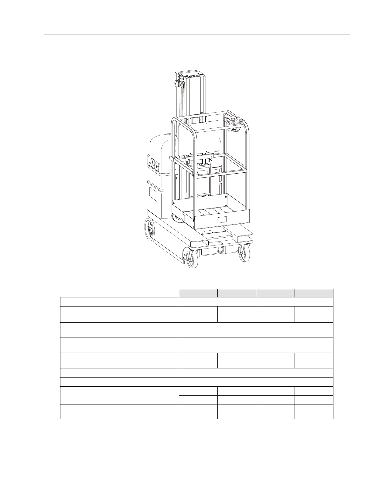
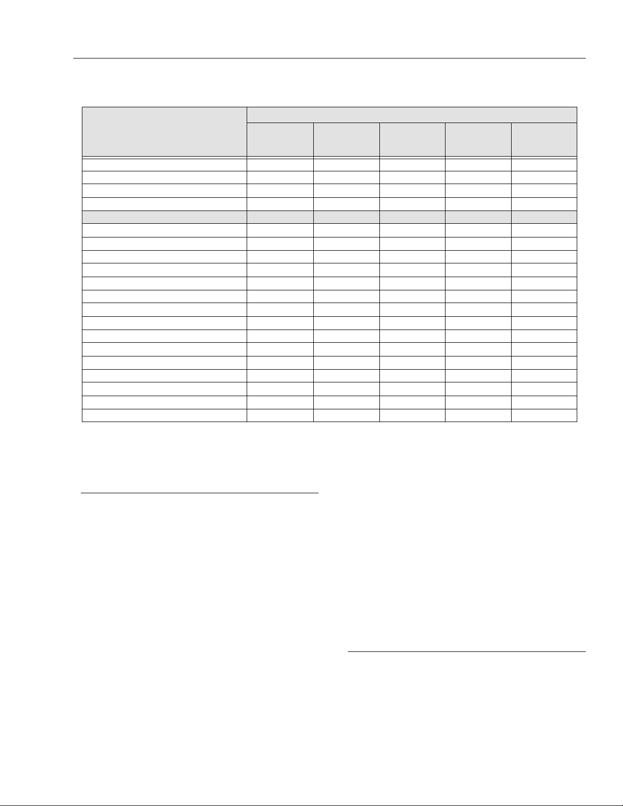
Table 1-1. DVL and DVSP - Machin e Spec i fications
15DVL 20DVL 15DVSP 20DVSP
Maximum Occupants: 1
Maximum W ork Load (Capacity) :
(DVL-Std. Platform / DVSP - Stockpicker Platform)
Maximum T r avel Grade (Gradeabilit y):
(Platform STOWED ONL Y)
Maximum T ravel Grade (Side Slope):
(Platform STOWED ONL Y)
Maximum Vertical Platform Height:
500 lb.
(230 kg)
15 ft.
(4.57 m)
350 lb.
(160 kg)
19.5 ft.
(5.94 m)
500 lb.
(230 kg)
20%
5°
15 ft.
(4.57 m)
Maximum Wheel Load (Per Wheel): 800 lb. (360 kg)
Maximum Drive Speeds (Operator Variabl e): 0.5 - 2 mph (0.8 - 3.2 kph)
Max. Platform Speeds (w/Max. Load): Platform Up:
Platform Down:
Gross Machine Weight (Platform Empty):
20 sec. 22.5 sec. 20 sec.
15 - 21 sec. 21 - 26 sec. 15 - 21 sec. 21 - 26 sec.
2,105 lb.
(955 kg)
2,105 lb.
(955 kg)
2,150 lb.
(975 kg)
400 lb.
(180 kg)
19.5 ft.
(5.94m)
22.5 sec.
2,150 lb.
(975kg)
3121136 – JLG Lift – 1-1
Page 14

SECTION 1 - MACHINE SPECIFICATIONS
1.1 CAPACITIES
System Voltage
All Models – 24 Volt DC
Hydraulic System
All Models – 5 qts. U.S. (4.7 L)
Drive Motor GearBox (gear oil)
All Models – 6 oz. (175cc)
1.2 COMPONENT DATA
Hydraulic Pump/Pump Motor Assembly
Pump Motor - 24 Volt DC motor, Standard Duty
Pump Displacement –
DVL/DVSP – .098 cu. in./rev. (1.6cc/rev.)
Pump Output (Max.) –
DVL/DVSP - 1.20 gpm @ 2200 psi @ 23.5 volts and 105
amps @ 45 centistrokes (200 SSU)
Reservoir Capacity –
DVL/DVSP - 1 Gallon (3.78 L)
Rear Wheel Drive Motors
Drive Motors -
1/2 HP, 24 Volt DC, Variable
Right Angle, Sealed Gear Box, 40:1 ratio
Brake Shaft and Drive Shaft - Integral to Moto r
Parking Brake ( m ust be released for pushing)
Batteries/ Battery Charger
Batteries (2) – 12 Volt / 100 Amp Hour –
Deep Cycle Marine - RV
Weight – 65.7 lb. (29.8 Kg) - Per Battery
1.3 PERFORMANCE DATA
Platform Cap a cities
Standard - 15DVL - 500 lb. (230kg)
20DVL - 350 lb. (160kg)
StockPicker - 15DVSP - 500 lb. (230kg)
20DVSP - 400 lb. (180kg)
Extendible - 15DVL/ 15DVSP - 500 lb. (230kg )
20DVL Series - 350 lb. (160kg)
Molded - 15DVL/15DVSP - 500 lb. (230kg)
20DVL Series - 350 lb. (160kg)
NOTE: Distribute weight evenly in platform when loading.
Reference the c apa city de cal on th e machi nes’ de cal
billboard mounted on mast.
Platform Size
Standard - 26in.-W x 26 in.-L (66cm) x (66cm)
Stockpicker - 28in.-W x 48in.-L (71cm x 122cm)
Extendible - 26in.-W x 49in.-L (66cm x 124cm)
Moulded - 25in.-W x 26in.-L (64cm x 66cm)
Machine Height (platform stowed)
DVL/DVSP - 78 in. (198cm) height
Base Footprin t
DVL/DVSP - 29.25in.-W x 52in.-L (74cm) x (132cm)
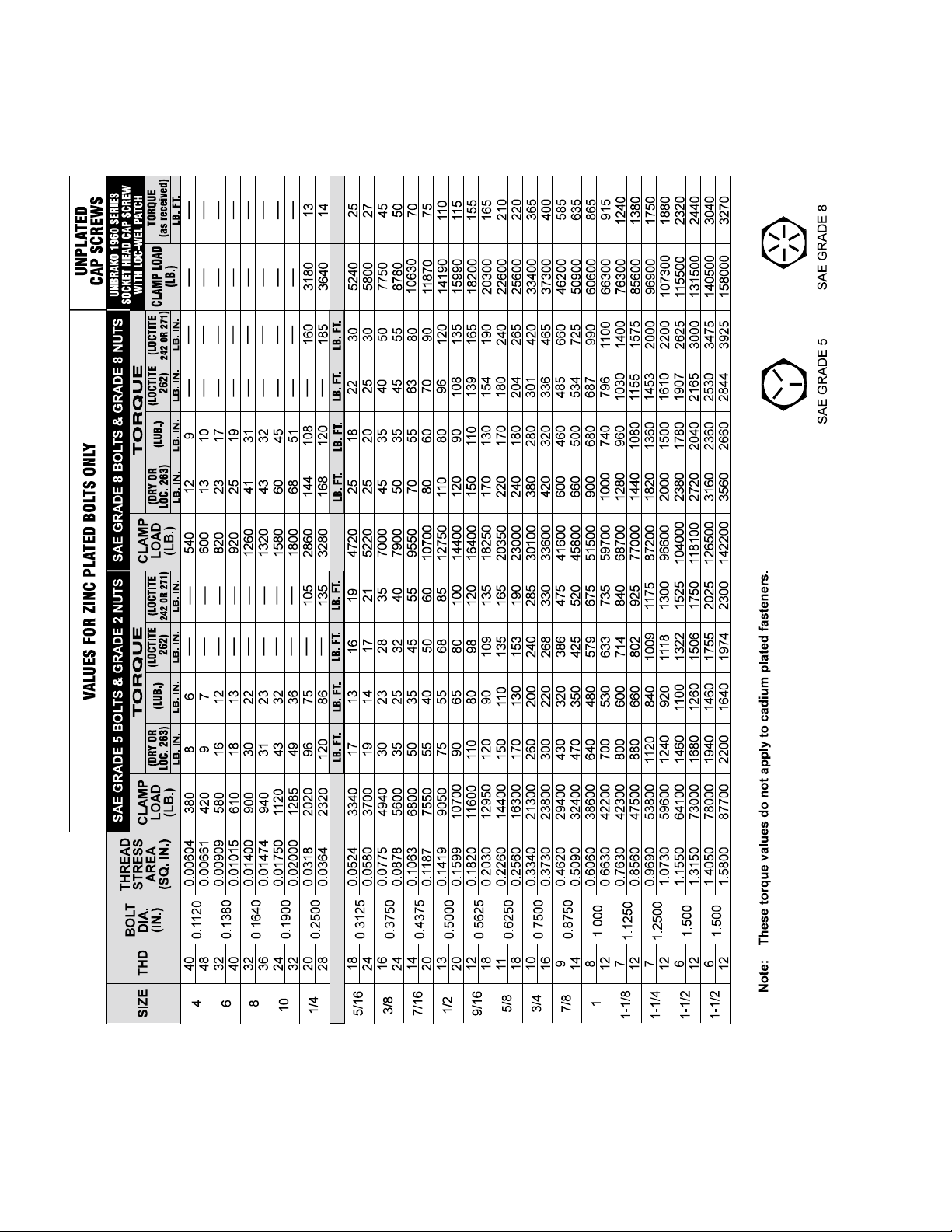
1.4 TORQUE REQUIREMENTS
When maintenance becomes necessary or a fastener has
loosened, refer to the applicable Torque Chart in this section
of the manual, to determine proper torque values.
Battery Charger –
Microprocessor Controlled/SCR Circuit Monitor
120/240 Volt A.C. Selectable / 50/60 Hz input
24 volt, 20 amp output - with 2 amp finish
Reset Circuit Breaker
Automatic Charge Circuit
Plug Interlock Circuit
Wet/VRLA Battery Switch
NOTE: The batteries on DVL/DVSP machines require
approximately five (5) hours to fully charge when
drained to LOW BATTERY VOLTAGE warning on the
Ground Control Module LCD display.
1-2 – JLG Lift – 3121136
Page 15

SECTION 1 - MA CHINE SPECIFICATIONS
1.5 LUBRICATION
Hydraulic Oil
Hydraulic oils must have anti-wear qualities at least to API
Service Classification GL-3, and sufficient chemical stability for mobile hydraulic system service. JLG Industries,
recommends Mob ilfluid 424 hydr aulic oil, which has an
SAE viscosity of 10W-30 and a viscosity index of 152.
For cold weather applications, i.e. when temperatures
remain consistently below +20°F (–7°C) JLG recommends using Mobil DTE 13 hydraulic oil.
Aside from JLG recommendations, it is not advisable to
mix oils of different brands or types, as they may not contain the same required add itives o r be of comp arable vis cosities. If use of hydraulic oil other than Mobilfluid 424 is
desired, contact JLG Industr ies for pr oper recommen dations.
Table 1-2. Hydraulic Oil Operating Range
HYDRAULIC SYSTEM OPERATING
TEMPERATURE RANGE
+0˚ F to +180˚ F
(-18˚ C to +83˚ C)
+0˚ F to +210˚ F
(-18˚ C to +99˚ C)
+50˚ F to +210˚ F
(+10˚ C to +99˚ C)
SAE VISCOSITY
GRADE
10W
10W-20, 10W-30
20W-20
1.6 HYDRAULIC PRESSURE SETTINGS AND ADJUSTMENT
Adjust system pressure so that p latform will rai se with ma ximum rated capacity in platform.
The following pressure setting are factory recommended
(initial) settings;
MODEL PRESSURE SETTING
15DVL/15DVSP 2600 PSI
20DVL 1800 PSI
20DVSP 2800 PSI
Turning adjustment screw clockwise increases sy stem
pressure, turning screw counterclockwise decreases system pressure. (See Figure 1-1., Hydraulic Press ure Adjust-
ment Screw. (Machine Rear Covers Removed))
Perform pressure ad justment with oil at normal operat ing
temperature. If pressure is set when oil is cold, platform may
not raise rated load after soil has warmed.
Lubrication Specifications
Table 1-3. Lubrication Specifications
KEY SPECIFICATIONS
MPG - Multipurpose Grease having a minimum dripping point
of 350° F . Excellent water resistance and adhesive qualities, and being of extreme pressure type. (Timken OK
40 pounds minimum.)
EPGL - Extreme Pressure Gear Lu be (oil) meeting AP I service
classification GL-5 or MIL -Spec MIL -L-2105.
HO - Hydraulic Oil. ISO- Vg grade 32, 46.
CL - Chain Lube. Use a good quality chain lubricant.
2
1
1. Remove Adjust Screw Cap 2. P ressure Ad justment Screw
Note: Machine rear covers must be removed to access pump motor.
Figure 1-1. Hydraulic Pressure Adjustment Screw.
(Machine Rear Covers Removed)
3121136 – JLG Lift – 1-3
Page 16
SECTION 1 - MACHINE SPECIFICATIONS
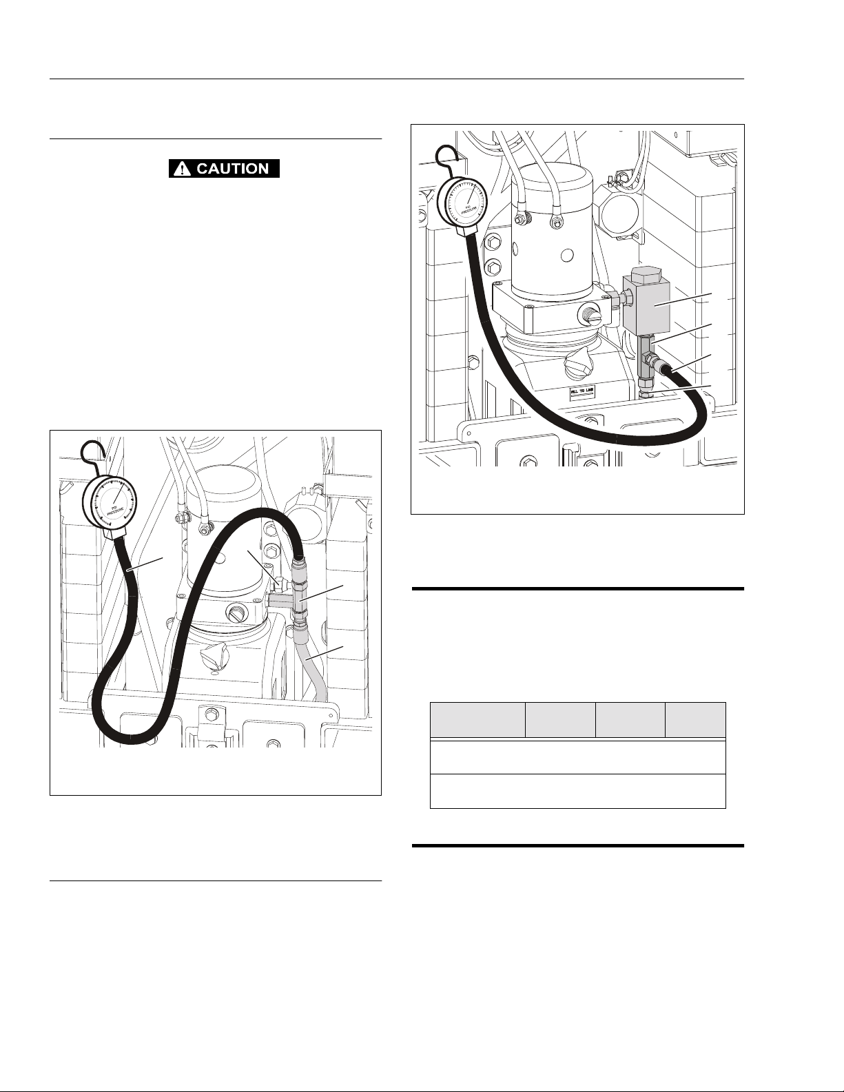
Hydraulic Press u r e Gaug e Connection
ONLY OPEN HYDRAULIC SYSTEM LINES WITH THE MAST FULLY
LOWERED TO RELIEVE PRESSURE IN THE SYSTEM. CAREFULLY
LOOSEN REQUIRED FITTINGS, WEAR SAFETY PROTECTION
EQUIPMENT WHEN WORKING WITH HYDRAULIC SYSTEMS.
Remove the hydraulic oil filter and ins tall a t-fitting between
the pump and the extend line to connect a hydraulic pressure gauge as shown in Figure 1-2., Typical Hydraulic Pressure Gauge Installation (Hydraulic Filter Removed).
CHECK, and if necessary, ADJUST the hydraulic pressure to
initial settings shown in table at the beginning of this section.
Cycle the hydraulic system several times with the maximum
load capacity in the platform, then recheck pressure setting.
When pressure has stabilized continue to "After Filter Pressure Check" following.
1
2
3
4
1
4
3
2
1. Pressure Gauge Assembly 3. T- Fitting
2. Extend Line 4. Return Line
Figure 1-2. Typical Hydrauli c P re s s ure Gauge
Installation (Hydraulic Filter Removed).
After Filter Pressure Check
Reinstall the hydraulic oil filter and install the t-fitting
between the hydraulic filter and the extend line to the cylinder. Recheck the hydraulic pressure and compare with the
previous r eadings when filter wa s removed. If a signi ficant
drop in pressure reading has occurred, replace the hydraulic filter and recheck the "after filter" pressure reading.
1. Hydraulic Oil Filter 3. Pressure Gauge Assembly
2. T- Fitting 4. Extend Line
Figure 1-3. Typical Hydraulic Pressure Gauge
Installation (After Hydraulic Filter).
1.7 CYLINDER SPECIFICATIONS
NOTE: All dimensions are given in inches (in), with the met-
ric equivalent, centimeters (cm), given in parentheses.
Table 1-4. Cylinder Specifications
DESCRIPTION
15DVL/15DVSP Lift Cylinder
20DVL/20DVSP Lift Cylinder
BORE
in./(cm)
1.63
(4.10)
1.63
(4.10)
STROKE
in./(cm)
41.50
(105.4)
54.0
(137.1)
ROD DIA.
in./(cm)
1.375
(3.49)
1.375
(3.49)
1.8 SERIAL NUMBER LOCATIONS
For machine identification, a serial number plate is affixed to
the machine. The plate is located on the back of the mast,
just above the mast support column.
1-4 – JLG Lift – 3121136
Page 17
SECTION 1 - MA CHINE SPECIFICATIONS
4
3
5
1
Table 1-5.Lubrication Intervals for Various Components
ITEM COMPONENT
1Hydraulic Oil
Drive Wheel
2
Bearings
Drive Wheel
3
Gear Box
4 Cas ter Axles 2 - Grease Fittings MPG - Pressure Gun
5 Swivel Raceways 2 - Front Casters MPG - Pressure Gun
6Mast Chains 2 - Per Section
Key to Lubr icants: MPG - Multipurpose Grease
HO - Hydraulic Oil - ISO-Vg grade 32, 46.
GEAR OIL - Good Quality Worm Gear Oil - SAE 90 - AGMA# 5 - EP Compounded
CL - Chain Lube. Use a good quality chain lubricant
NO/TYPE
LUBE POINTS
Fill T o Line on
Reservoir
5 Qt. Rese rvoir
2 - Gear Boxe s G ear Oil
(a)
LUBE/METHOD
HO - Check Hyd. Oil
Level
HO - Change Hyd. Oil
— — Permanently Sealed.
Chain Lube - Brush or
Spray
2
INTERVAL
3
MONTHS6MONTHS1YEAR2YEARS
(b)
COMMENTS
Check fluid level every day .
✔
Change hydraulic oil every 2
years.
Change only when serviced
requires 6 oz. (175 cc’s) to fill.
(c)
✔
✔
✔
Inspect, lubricate if dry or rusting.
Notes: (a) Be certain to lubricate like items on each side of the machine.
such as a high number of cycles, location, corrosive/dirty environment, etc., user must adjust lubricating requirements accordingly.
(b) Recommended lubricating intervals are based on normal use. If machine is subjected to severe operating conditions,
(c) Prior to checking hydraulic oil level, operate machine through one complete cycle of lift function (full up and down). F ailure to do so
will result in incorrect o il level readi ng on the hydrau lic reservoir .
3121136 – JLG Lift – 1-5
Page 18
SECTION 1 - MACHINE SPECIFICATIONS
Figure 1-4. Torque Chart. (ANSI Spec.)
1-6 – JLG Lift – 3121136
Page 19
UNPLATED
CAP SCREWS
SECTION 1 - MA CHINE SPECIFICATIONS
SAE GRADE 5 SAE GRADE 8
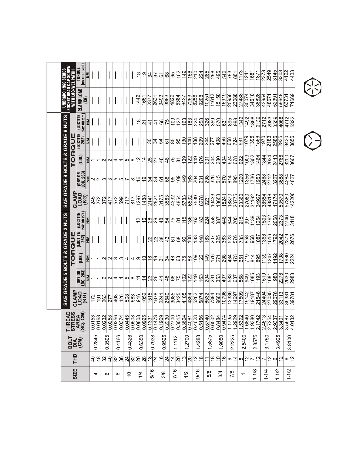
VALUES FOR ZINC PLATED BOLTS ONLY
Note: These torque values do not apply to cadium plated fasteners.
Figure 1-5. T orque Chart. (ANSI to METRIC Conversion)
3121136 – JLG Lift – 1-7
Page 20
SECTION 1 - MACHINE SPECIFICATIONS
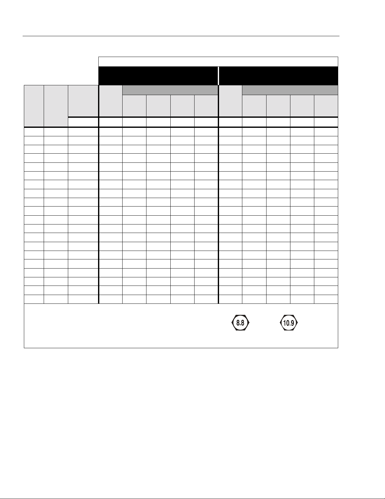
VALUES FOR ZINC PLATED / YELLOW CHROMATE FASTENERS ONLY
CLASS 8.8 ME TRIC BOLTS &
CLASS 8 METRIC NUTS
TORQUE
LUB
LOCTITE
262
LOCTITE
242 OR
271
CLAMP
SIZE PITCH
TENSILE
STRESS
AREA
CLAMP
LOAD
DRY OR
LOCTITE
263
sq. mm KN N, m N, m N, m N, m KN N, m N, m N, m N, m
3 .5 5.03 2.19 1.3 1.0 1.2 1.4 3.13 1.9 1.4 1.5 2.1
3.5 .6 6.78 2.95 2.1 1.6 1.9 2.3 4.22 3.0 2.2 2.4 3.3
4 .7 8.78 3.82 3.1 2.3 2.8 3.4 5.47 4.4 3.3 3.5 4.8
5 .8 14.2 6.18 6.2 4.6 5.6 6.8 8.85 8.9 6.6 7.1 9.7
6 1 20.1 8.74 11 7.9 9.4 12 12.5 15 11 12 17
7 1 28.9 12.6 18 13 16 19 18 25 19 20 28
81.2536.615.92519232822.837272940
10 1.5 58.0 25.2 50 38 45 55 36.1 72 54 58 79
12 1.75 84.3 36.7 88 66 79 97 52.5 126 95 101 139
14 2 115 50.0 140 105 126 154 71.6 200 150 160 220
16 2 157 68.3 219 164 197 241 97.8 313 235 250 344
18 2.5 192 83.5 301 226 271 331 119.5 430 323 344 473
20 2.5 245 106.5 426 320 383 469 152.5 610 458 488 671
22 2.5 303 132.0 581 436 523 639 189.0 832 624 665 915
24 3 353 153.5 737 553 663 811 220.0 1060 792 845 1170
27 3 459 199.5 1080 810 970 1130 286.0 1540 1160 1240 1690
30 3.5 561 244.0 1460 1100 1320 1530 349.5 2100 1570 1680 2310
33 3.5 694 302.0 1990 1490 1790 2090 432.5 2600 2140 2280 2860
36 4 817 355.0 2560 1920 2300 2690 509.0 3660 2750 2930 4020
42 4.5 1120 487.0 4090 3070 3680 4290 698.0 5860 4400 4690 6440
CLASS 10.9 METRIC BOLTS &
CLASS 10 METRIC NUTS
LOAD
DRY OR
LOCTITE
263
LUB
TORQUE
LOCTITE
262
LOCTITE
242 OR
271
Note: These torque value s do not apply to cadmium plated fa steners.
METRIC CLASS 8.8 METRIC CLASS 10.9
Figure 1-6. Torque Chart (Metric Class Fasteners)
1-8 – JLG Lift – 3121136
Page 21

SECTION 2. GENERAL
SECTION 2 - GENERAL
2.1 MACHINE PREPARATION, INSPECTION, AND MAINTENANCE
General
This section provides the necessary information needed
by those personnel that are responsible to place the
machine in operation readiness and maintain its safe
operating condition. For maximum service life and safe
operation, ensure that all the necessary inspections and
maintenance have been completed before placing the
machine into service.
Preparation, Inspection, and Maintenance
It is important to establish and conform to a comprehensive inspection and preventive maintenance program. The
following table outlines the periodic machine inspections
and maintenance recommended by JLG Industries, Inc.
Consult your national, regional, or local regu lat io ns for further requirements for aerial work platforms. The frequenc y
of inspections and maintenance must be increased as
environment, severity and frequency of usage requires.
Pre-Start Inspection
It is the User’s or Operator’s primary responsibility to perform a Pre-Start Inspection of the machine prior to use
daily or at each change of operator. Reference the Operator’s and Safety Manual for completion procedures for the
Pre-Start Inspection. The Operator and Safety Manual
must be read in its entirety and understood prior to performing the Pre-Start Inspection.
Pre-Delivery Inspection and Frequent Inspection
The Pre-Delivery Inspection and Frequent Inspection shall
be performed by a qualified JLG equipment mechanic.
JLG Industries, Inc. recognizes a qualified JLG equipment
mechanic as a person who, by possession of a recognized degree, certificate, extensive knowledge, tra ini ng, or
experience, has successfully demonstrated the ability and
proficiency to service, repair, and maintain the subject
JLG product model.
The Pre-Delivery Inspection and Frequent Inspection procedures are performed in the same manner, but at different times. The Pre-Delivery Inspection shall be performed
prior to each sale, lease, or rental delivery. The Frequent
Inspection shall be accomplished for each machine in service for 3 months; out of service for a period of more than
3 months; or when purchased used. The frequency of this
inspection must be increased as environment, severity
and frequency of usage requires.
Reference the JLG Pre-Delivery and Frequent Inspection
Form and the Inspection and Preventative Maintenance
Schedule for items requirin g inspection during the performance of these inspections. Reference the appropriate
areas of this manual for servicing and maintenance procedures.
Annual Machine Inspection
The Annual Machine Inspection must be performed by a
qualified JLG equipment m echan ic on an annual b asis, n o
later than thirteen (13) months from the date of the prior
Annual Machine Inspection. JLG Industries, Inc. recognizes a qualified JLG equipment mechanic as a person
who has successfully completed the JLG Servic e Training
School for the subject JLG product model. Reference the
machine Service and Maintenance Manual and appropriate JLG inspection form for performance of this inspection.
Reference the JLG Annual Machine Inspection Form and
the Inspection and Preventative Maintenance Schedule for
items requiring inspection during the performance of this
inspection. Reference the appropriate areas of this manual for servicing and maintenance procedures.
For the purpose of receiving safety-related bulletins, it is
important that JLG Industries, Inc. has updated ownership
information for each machine. When performing each
Annual Machine Inspection, notify JLG Industries, Inc. of
the current machine ownership.
Preventative Maintenance
In conjunction with the specified inspections, maintenance shall be p erformed by a qualifie d JLG equipment
mechanic. JLG Industries, Inc. recognizes a qualified JLG
equipment mechan ic as a pe rson who, by p osse ssio n of a
recognized degree, certificate, extensive knowledge, training, or experience, has successfully demonstrated the
ability an d profici ency to service , repair, and mainta in the
subject JLG product model .
Reference Table 2-2, DVL/DVSP - Preventive Maintenance
& Inspection Schedule., and the approp riate areas of this
manual for servicing and maintenance procedures. The
frequency of service and maintenance must be increased
as environment, severity and frequency of usage requires.
3121136 – JLG Lift – 2-1
Page 22

SECTION 2 - GENERAL
Table 2-1. Inspection and Maintenance
Type Frequency
Pre-Start
Inspection
Pre-Delivery
Inspection
Frequent
Inspection
Annual
Machine
Inspection
Preventative
Maintenance
Prior to use each day; or
At each Operator change.
Prior to each sale, lease, or
rental delivery.
In service for 3 months; or Out of service
for a period of more than 3 months; or Purchased used.
Annuall y, no lat er than 13 months from the
date of the prior inspecti on.
At intervals as specified in the Service and
Maintenance Manual.
Primary
Responsibility
User or Operator User or Operator Operator and Safety Manual
Owner , Dealer , or User Qualified JLG
Owner , Dealer , or User Qualified JLG
Owner , Dealer , or User Qualified JLG
Owner , Dealer , or User Qualified JLG
Service
Qualification
Mechanic
Mechanic
Mechanic
Mechanic
Reference
Service and Maintenance Manual and applicable JLG ins pection form.
Service and Maintenance Manual and applicable JLG ins pection form.
Service and Maintenance Manual and applicable JLG ins pection form.
Service and Maintenance Manual
2-2 – JLG Lift – 3121136
Page 23

2.2 PREVENTIVE MAINTENANCE AND INSPECTION SCHEDULE
(See T able 2-2.)
The preventive maintenance and inspection checks are
listed and defined in the following table. This table is
divided into t wo basic parts, the “AREA” to be inspected
and the “INTERVAL” at which the inspection is to take
place. Under the “AREA” portion of the table, the various
systems along with the components that make up that
system are listed. The “INTERVAL” portion of the table is
divided into five col umn s repr ese ntin g t he vari ous i nspe ction time periods. The numbers listed within the interval
column represent the applicable inspection code for
which that component is to be checked.
The checks and services listed in this schedule are not
intended to replace any local or regional regulations that
may pertain to this type of equipment nor should the lists
be considered as all inclusive. Variances in interval times
may occur due to climate and/or c ondition s and de pending on the location and use of the machine.
SECTION 2 - GENERAL
3121136 – JLG Lift – 2-3
Page 24

SECTION 2 - GENERAL
a
Table 2-2. DVL/DVSP - Preventive Maintena nce & Inspection Schedule.
INTERVAL
AREA ON MACHINE
PRE-START (a)
INSPECTION
3 MONTH
PREVENTATIVE
MAINTENANCE
MAST ASSEMBL Y 7
Mast Sections 2, 5 2, 5
Chain Systems 14 3, 14 14, 25
Sequence Cable Systems 31, 2, 3
Covers or Shields 1
Sheave Systems 1, 2 1, 2
Bearings 1, 2
Slide Pads 1, 2
PLATFORM ASSEMBLY 7
Platform 11
Guard Rails 1, 2, 4 1, 2, 4
Gate 1, 5 1, 5
Floor 1, 2 1, 2
Extension Deck Assembly 1, 5 1, 5
Lanyard Anch orage Point 1, 4 1, 4
CHASSIS ASSEMBL Y 7
Pot Hole Protection System 55
Battery and Valve Covers or Doors 1, 7 1, 7
Static Strap
Caster Wheels 1, 2 14 1, 2 1, 2
Drive Wheels/Axle Assembly 22
Gear Box Assembly *
Drive Motor Brushes 2, 20
T orque Limit Clutch ** 1, 7 3
Brake Release 55
FUNCTIONS/CONTROLS 7
Platform Controls 5, 6, 7 5, 6, 7
Ground Controls 5, 6 5, 6, 14
Functi on Control Lo cks, Guards, o r Detents 55
Function Enable System
Emergency Stop Switches (Ground & Platform) 5
Functi on Limit or Cuto ut Switch Syste ms 5
Drive Brakes 5
Manual Descent or Auxiliary Power 55
POWER SYSTEM
Batteries 19 9 18
Battery Charger 5
HYDRAULIC/ELECTRIC SYSTEM 9
Hydraulic Pump 1, 2, 9 1, 2, 5, 9
Hydraulic Cylinder 2, 7, 9 2, 9
Cylinder Attachment Pins and Pin Retainers 1, 2 1, 2
Hydraulic Hoses, Lines, and Fittings 1, 9 1, 9
Hydraulic R eservoir , Cap, and Breather 5, 7 5, 7
6 MONTH
PREVENTATI VE
MAINTENANCE
PRE-DELIVERY (b)
OR FREQUENT (c )
INSPECTION
ANNUAL (d)
(YEARLY)
INSPECTION
2-4 – JLG Lift – 3121136
Page 25
SECTION 2 - GENERAL
Table 2-2. DVL/DVSP - Preventive Maintenance & Inspection Schedule. (Continued)
INTERVAL
AREA ON MACHINE
PRE-START (a)
INSPECTION
3 MONTH
PREVENTATIVE
MAINTENANCE
Hydraulic Filter
Hydraulic Fluid *** 11 11 11
Electrical Connections 20 20
Instruments, Gauges, Switches, Lights, Ho rn 5
GENERAL
Operator and Safety Manuals in Storage Box 21 21 21
ANSI and EMI M anuals/Handbooks I nstalled 21 21 21
Capacity Decals Ins talled, Secure, Legible 21 21 21
All Decals/Placards In stalled, Secure, Legible 21 21 21
"Walk-Around" Inspection Performed 22
Annual Machine Inspection Due 21
No Unauthorized Modifications or Additions 21 21
All Relevant Saf ety Publications Incorporat ed 21 21, 22
General Structural Condition and Welds 2, 4 2, 4
All Fasteners, Pins , Shields, and Covers 1, 2
Grease and Lubricate to Specifications 22 22
Function Test of All Systems 22 22
Paint and Appearance 77
Stamp Inspec tion Date on Fra me 22
Notify JLG of Machine Ownership 22
* Change only when serviced, requires 6 oz. (175cc’s) to fill.
** If the lift is moved via fork truck on a regular or frequent basis, then the torque set ting should be checked every 3 months per Section 3 (of this
manual) - Drive Motor Component Servicing.
*** Drain and refill with fresh hydraulic fluid every two years.
6 MONTH
PREVENTATI VE
MAINTENANCE
PRE-DELIVERY (b)
OR FREQUENT (c )
INSPECTION
ANNUAL (d)
(YEARLY)
INSPECTION
Inspection and Maintenance Codes:
1. Check for proper and secure installation.
2. V isual inspection for damage, cracks, disto rtion, or
excessive wear.
3. Check for proper adjustment.
4. Check for cracked or broken welds.
5. Operates properly.
6. Returns to neutral or "off" position when released.
7. Clean and free of debris.
8. Interlocks function properl y.
9. Ch eck for signs of leakage.
16. No gouges, excessive wear, or cords showing.
17. Properly inflated and seated around rim .
18. Proper and authorized components.
19. Fully charged.
20. No loose connections, corrosion, or abrasions.
21. Verify.
22. Perform.
23. Sealed properly.
24. Overrides Platform controls.
25. Inspected per Ser vice and Maintenance Manual.
Footnotes:
10. Decals installed and legible.
11. Check for proper fluid level.
12. Check for chafing and proper routing.
13. Check for proper tolerances.
14. Properly lubricated.
15. Torqued to proper specification.
(a) Prior to use each day; or at each Operator change
(b) Prior to each sale, lease, or deliv ery
(c) In service for 3 months; or Out of service for 3 months
or more; or Purchased used
(d) Annually, no later than 13 months from the date of the
prior inspection
3121136 – JLG Lift – 2-5
Page 26
SECTION 2 - GENERAL
2.3 SERVI CING AND MAINTENANCE GUIDELINES
General
The following information is provided to assist you in the
use and application of servicing and maintenance procedures contained in this chapter.
Safety and Workmanship
Your safety, and that of others, is the first consideration
when engaging in the maintenance of equipment. Always
be conscious of component weight. Never attempt to
move heavy parts without the aid of a mechanical device.
Do not allow heavy objects to rest in an unstable position.
When raising a portion of the equipment, ensure that adequate support is provided.
NEVER WORK UNDER AN ELEVATED PLATFORM UNTIL PLATFORM HAS BEEN SAFELY RESTRAINED FROM ANY MOVEMENT
BY BLOCKING OR OVERHEAD SLING.
Cleanliness
The most important single item in preserving the long service life of a machine is to keep dirt and foreign materials
out of the vital components. Precautions have been taken
to safeguard against this. Shields, covers, seals, and filters are provided to keep the wheel bearings, mast sections and oil supply clean; however, these items must be
maintained on a scheduled basis in order to function
properly.
At any time when oil lines are disconnected, clear adjacent areas as well as the openings and fittings themselves. As soon as a line or component is disconnected,
cap or cover all openings to prevent entry of foreign matter.
Clean and inspect all parts during servicing or maintenance, and assure that all passages and openings are
unobstructed. Cover all parts to keep them clean. Be sure
all parts are clean before they are installed. New parts
should remain in their containers unt il they are ready to be
used.
Components Removal and Installation
Use adjustable lifting devices, whenever possible, if
mechanical assistance is required. All slings (chains,
cables, etc.) should be parallel to each other and as near
perpendicul ar as pos s ible to top of part being lifted.
Should it be necessary to remove a component on an
angle, keep in mind that the capacity of an eyebolt or similar bracket lessens, as the angle between the supporting
structure and the component becomes less than 90
degrees.
If a part resists removal, check to see whether all nuts,
bolts, cables, brackets, wiring, etc., have been removed
and that no adjacent parts are interfering.
Component Disassembly and Reassembly
When disassembling or reassembling a component, complete the procedural steps in sequence. Do not partially
disassemble or assemble one part, th en start on anothe r.
Always recheck your work to assure that nothing has been
overlooked. Do not make any adjustments, other than
those recommended, without obtaining proper approval.
Pressure-Fit Parts
When assembling pressure-fit parts, use an “anti-seize” or
molybdenum disulfide base compound to lubricate the
mating surface.
Bearings
When a bearing is removed, cover it to keep out dirt and
abrasives. Clean bearings in nonflammable cleaning solvent and allow to drip dry. Compressed air can be used
but do not spin the bearing.
Discard bearings if the races and balls (or rollers) are pitted, scored, or burned.
If bearing is found to be serviceable, apply a light coat of
oil and wrap it in clean (waxed) paper. Do not unwrap
reusable or new bearings until they are ready to install.
Lubricate new or used serviceable bearings before installation. When pressing a bearing into a retainer or bore,
apply pressure to the outer race. If the bearing is to be
installed on a shaft, apply pressure to the inner race.
Gaskets
Check that holes in gaskets align with openings in the
mating parts. If it becomes necessary to hand-f abricate a
gasket, use gasket material or stock of equivalent material
and thickness. Be sure to cut holes in the right location, as
blank gaskets can cause serious system damage.
Bolt Usage and Torque Application
Use bolts of proper length. A bolt which is too long will
bottom before the head is tight against its related part. If a
bolt is too short, there will not be enough thread area to
engage and hold the part properly. When replacing bolts,
use only those having the same specifications of the original, or one wh ich is equivalent.
Unless specific torque requirements are given within the
text, standard torque values should be used on heattreated bolts, studs, and steel nuts, in accordance with
recommended shop practices or Torque Chart in Section
1.
2-6 – JLG Lift – 3121136
Page 27

SECTION 2 - GENERAL
Hydraulic Lines and Electrical Wiring
Clearly mark or tag hydraulic li nes a nd electrical wirin g, as
well as their receptacles, when disconnecting or removing
them from the unit. This will assure that they are correctly
reinstalled.
Hydraulic System
Keep the system clean. If evidence of metal or rubber particles is found in the hydraulic system, drain and flush the
entire system.
Disassemble and reassemble p arts on clean work surface. Clean all metal parts with non-flammable cleaning
solvent. Lubricate components, as required, to aid assembly.
Lubrication and Servicing
Componen ts and as sembli es requ iring l ubricat ion and
servicing are shown in the Lubrication Chart , (See Sec-
tion-1). Servi ce applicabl e components wit h the amount,
type, and grade of lubricant recommended in this manual,
at the specified intervals . When recom mended lubric ants
are not available, consult your local supplier for an equivalent that meets or exceeds the specifications listed.
Batteries
Clean batteries, using a non-metallic brush and a solution
of baking soda and water. Rinse with clean water. After
cleaning, thoroughly dry batteries and coat terminals with
an anti-corrosion compound.
Mast Chain Inspection Procedure
Inspect mast chains for the follow ing condi t io ns :
Wear: Always inspect that segment of chain that operates
over a sheave. As the chain flexes over the sheaves, joints
and plate edges very gradually wear. Chain “stretch” can
be measured using a manufacturers wear scale or steel
tape. When chains have elongated 3% they must be
removed and replaced. Refer to Table 2-3 for proper chain
specifications and allowable stretch tolerances. Peening
and wear of chain plate edges are caused by sliding over
a chain worn contact face of a sheave , or unusually heavy
loads. All of the above require replacement of the chain
and correction of the cause. Chain side wear, noticeable
when pin heads and outside plates show a definite wear
pattern, is caused by misalignment of the s heave/chain
anchors and must be corrected promptly. Do not repair
chains; if a section of chain is damaged, replace the entire
chain set.
Rust and Corrosion: Rust and corrosion will cause a
major reduction in the load carrying capacity of the chain,
because these are primary reasons for side plate cracking. The initial lubric ation at the factory is applied in a hot
dip tank to assure full penetration into the joint. Do not
steam clean or degrease chains. At time of chain installation, factory lube must be supplemented by a maintenance program to provide a film of oil on the chain s at all
times. If chains are corroded, they must be inspected,
especially the outside plates, for cracks in-line with the
pins. If cracks are found, replace the chain; if no cracks
are discovered, lubricate the chains by dipping in heated
oil, and reinstall on the machine. Keep chains lubricated.
Table 2-3. Chain Stretch Tolerance
Chain Size
.50" pitch 12" or 24 pitches .24 in./12 in. span
.625 pitch 15" or 24 pitches .30 in./15 in. span
Fatigue Cracks: Fatigue is a phenomenon that affects
most metals, and is the most common cause of chain
plate failures. Fatigue cracks are found through the link
holes, perpendicular (90 degrees) from the pin in-line
position. Inspect chains carefully after long time use and
heavy loading for this type of crack. If any cracks are discovered, replace all chains, as seemingly sound plates
are on the verge of cracking. Fatigue and ultimate
strength failures on JLG Lifts are incurred as a result of
severe abuse as design specs are well within the rated lifting capacity of these chains.
Tight Joints: All joints in the leaf chain should flex freely.
On leaf chain, tight joints are usually caused by rust/corrosion, or the inside plates “walking” off the bushing. Limber
up rusty/corroded chains (after inspecting care fully) with
a heavy application of oil (preferably a hot oil dip). Tap
inside “walking” plates inward; if “walking” persists,
replace the chain. This type of problem is accelerated by
poor lubrication maintenance practice, and most tight
joint chains have been operated with little or no lubrication. Tight joints on leaf chain are generally caused by:
a. Bent pins or plates .
b. Rusty joints.
c. Peened plate edges.
Oil rusty chains, and repl ace chai ns with b ent or pee ned
chain components. Keep chains lubricated.
Protruding or Turned Pins: Chains operating with inadequate lube generate tremendous friction between the pin
and plates (pin and bushing on leaf chain). In extreme
cases, this frictional torque ca n actually turn the pins in
the outside press-fit plates. Inspect for turned pins, which
can be easily spotted as the “V” flats on the pin heads are
no longer in line. Replace all chains showing evidence of
turned or protruding pins. Keep chains lubricated.
Chain Anchors and Sheaves: An inspection of the cha in
must include a close examination of chain anchors and
sheaves. Check chain anchors for wear breakage and
misalignment. Anchors with worn or broken fingers should
Pin to Pin
Measurement
Allowable Stretch
3121136 – JLG Lift – 2-7
Page 28

SECTION 2 - GENERAL
be replaced. They should also be adjusted to eliminate
twisting the chain for an even load distribution.
Inspect the sheaves, sheave bearings, sheave grooves
and pins for extreme wear, replace as necessary. A worn
sheave can mean several problems, as follows:
a. Chains too tight.
b. Sheav e be arings/pin bad.
c. Bent/misaligned chains.
2.4 LUBRICATION INFORMATION
Hydraulic System
The primary enemy of a hydraulic system is contamination. Contaminants enter the system by various means,
e.g., using inadequate hydraulic oil, allowing moisture,
grease, filings, sealing components, sand, etc., to enter
when performing maintenance, or by permitting the pump
to cavitate du e to ins ufficie nt sys tem wa rm-up o r leaks in
the pump supply.
The design and manufacturing toler ances of the component working parts are very close, therefore, even the
smallest amount of dirt or foreign matter entering a system
can cause wear or damage to the components and generally results in faulty operation. Every precaution must be
taken to keep hydraulic oil clean, including reserve oil in
storage.
Cloudy oils indicate a high moisture content which permits organic growth, resulting in oxidation or corrosion. If
this condition occurs , the system mus t be drained,
flushed, and refilled with clean oil.
It is not advisable to mix oils of different brands or types,
as they may not contain the same required additives or be
of comparable vi scosities. Good g rade min eral oils, w ith
viscosities suited to the ambient temperatures in which
the machine is operating, are recommended for use.
NOTE: Metal particles may appear in the oil of new
machines due to the wear-in of meshing components.
Hydraulic Oil
For best performance, JLG recommends the use of ISOVg grade 32, 46 oil with a viscosity range between 15-250
SUS at 100 degrees F (32-54 cST at 40 degrees C). Refer
to Section 1-5 of this Service Manua l for recommended
hydraulic oils.
Changing Hydraulic Oil
Use of any of the recommended hydraulic oils eliminates
the need for changing the oil on a regular basis. If it is necessary to change the oil, use only those oils meeting or
exceeding the specifica tions app earing i n this manua l. If
unable to obtain the same type of oil supplied with the
machine, consult local supplier for assistance in selecting
the proper equivalent. Avoid mixing petroleum and synthetic base oil s. JLG I ndus tri es rec omme nds c ha nging th e
hydraulic oil annually.
Use every precaution to keep the hydraulic oil clean. If the
oil must be pou red from the origi nal container into
another, be sure to clean all possible contaminants from
the service container.
While the unit is shut down, a good preventive maintenance measure is to make a thorough inspection of all
hydraulic components, lines, fittings, etc., as well as a
functional check of each system, before placing the
machine back in service.
Lubrication Specifications
Specified lubricants, as recommended by the component
manufacturers, are always the be st choice, however,
multi-purpose greases usually have the qualities which
meet a variety of single purpose grease r equirements.
Should any question arise regarding the use of greases in
maintenance s t ock, cons ul t yo ur lo cal su ppl ier f o r e valu a tion. Refer to Section-1 in this Service Manual for an explanation of the lu bricant key de signatio ns appe aring in the
Lubrication Chart.
2-8 – JLG Lift – 3121136
Page 29
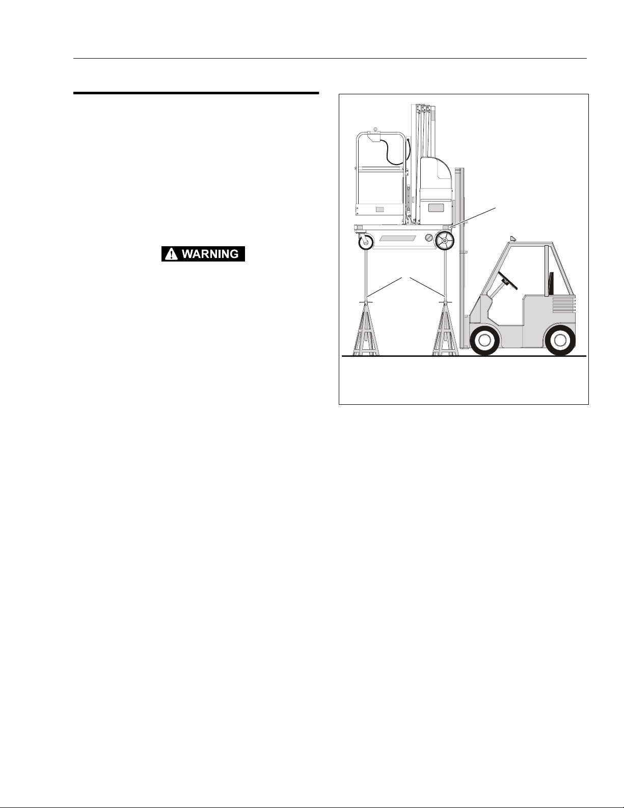
2.5 POSITIONING LIFT FOR ACCESS TO COMPONENTS LOCATED UNDER THE BASE FRAME
Access to the underside of the VP lift can be obtained by
lifting the machine with a fork lift truck, using the fork lift
pockets in the base frame.
Lifting with a Fork Truck (See Figure 2-1.)
1. Choose a fork lift truck capable of safely handling
the full weight of the machine.
2. Locate work area on a firm, level surface.
SECTION 2 - GENERAL
1
KEEP MACHINE LEVEL OR SLIGHTLY TILTED TOWARD FORKLIFT TRUCK WHEN LIFTING TO PREVENT MACH INE FROM SLIDING OFF LIFTING TINES.
3. When lifting with a fork truck, lift only using the fork
lift-truck pockets running the length of the machine’s
base frame from rear to front.
4. After lifting machine to desired work height, place
support stands under the machine. The support
stands must reach from the floor to the bottom of the
machine and be capable of safely handling the
weight of the machine.
2
1. Lift using only the fork lift pockets in the base frame.
2. Place support stands between machine and floor.
Figure 2-1. Accessing Machine Underside
Components by Lifting with a Fork Truck.
3121136 – JLG Lift – 2-9
Page 30

SECTION 2 - GENERAL
This page intentionally left blank.
2-10 – JLG Lift – 3121136
Page 31

SECTION 3. BASE COMPONENTS
3.1 BASE ASSEMBLY COMPONENTS
1
2
3
4
SECTION 3 - BASE COMPONENTS
11
5
6
7
9
8
10
1. Base Mounted Beacon 4. Base Frame 7. Pot Hole Protection System 10. Drive Motor Cover
2. Battery Charger Cover 5. Front Caster Wheels 8. Drive Motor Mount Assy.- (To S/N-0130005270) 11. Rear Tie Down Lug
3. Battery Charger Assembly 6. Front Tie Down Lug 9. Drive Motor Mou n t Assy.- (Since S/N-0130005271)
Figure 3-1. Base Components.
3121136 – JLG Lift – 3-1
Page 32

SECTION 3 - BASE COMPONENTS
3.2 BASE FRAME COVERS Drive Motor Cover - Installation
3
2
1. Hex Head Screws/Washers - 3. Drive Motor Mount
(Apply Loctite 242) 4. Motor Mount Interlo ck Slots
2. Front Support Tab 5. Static Strap
4
4
5
Battery Charger Cover - Installation
3.3 DRIVE AND CASTER WHEELS Drive Motor Wheel (Std.) - Installation
1
6
5
4
3
2
1
1. Wheel Retaining Screw (a) 4. Drive Wheel
2. Retaining Washer 5. Drive Shaft Key
3. 2mm x 10mm Dia. Washer (b) 6. Drive Shaft Key Slot
Note: (a) On assembly, apply Loctite 242, torque to 35 ft. lb.
(b) Install as require d ; Must be .005" minimum distance
between retaining washer (item 2) and wheel hub face
(item 4) with retaining screw torqued.
1
4
2
3
1. Battery Charger Cover 3. Hex Head Screws/Washers
2. Cap Screws/Washers 4. Base Mounted Beacon (a)
Note: (a) Standard on DVSP; Option on DVL Series
Caster Wheels - Installation
3
2
1
1. Caster Wheel Assembly 3. Caster Shim (b)
2. Hex Head Screw/Flat Washer (a)
Note: (a) On assembly, apply Loctite 242 to threads.
(b) As required; Place unit on a flat surface, shim a caster
wheel that is more than .015" off of flat surface.
3-2 – JLG Lift – 3121136
Page 33

SECTION 3 - BASE COMPONENTS
Wheel Retention for Rough Terrain Drive Wheel (Option)
1. The rought terrain drive wheel is installed same as
the regular drive wheel except - place the wheel onto
drive motor shaft ensuring that the deepest point of
the rim, 5/8" as shown below, is facing out.
Failure to do so will resul t in the drive wh eel rubbin g
the drive motor cover.
5/8”
Note* Do not forget to replace
shim(s), .005”min. Gap is
critical be tween retaining
washer and wheel hub.
3.4 DRIVE MOTOR COMPONENT SERVICING
Torque Limiting C lutch Maintenance
DVL Series and DVSP machines are equipped with a torque
limiting clutch coupling on each drive axle. The clutch is
mounted in line on a split drive axle between the drive wheel
and the drive motor gear box. The clutch is designed to slip
at a preset torque (220 ft. lb.) if the machines rear wheels are
over-driven while the machine is being towed, pushed or
forklifted, thus preventing damage to the drive gear box.
Although factory pre-set, the clutch assembly torque setting
should be checked;
• Annually - during Annual In s pec t ion
However, if the lift is being moved via a fork truck on a regular or frequent basis, then the torque clutch may be forced
into a slipping mode, as intended to protect the drive train.
In that case, and if slippage occurs during ma chine operation, then the torque setting should be checked;
• Every 3 Months
And the torque specification reset per the following instructions.
2. Replace shims and the retaining was her.
3. Apply Loctite #242 onto retaining screw and install
with a torque rating of 35 ft lb.
IMPORTANT
FAILURE TO APPLY LOCTITE #242 TO THE RETAINING SCREW
AND TORQUING THE RE TAINING SCREW TO 35 FT LB MA Y
RESULT IN THE WHEEL COMING LOOSE AND FALLING OFF
Diagnostics
A torque clutch with INCORRECT torque setting may
develop the following symptoms;
• Machine does not drive straight .
NOTE: Machine pu lling to one side can also be the result of
low battery voltage. Be sure and check battery voltage before clutch main t ena nce begins.
•There is gray dust accumulating around the drive
motor(s) due to excessive clutch wear.
3121136 – JLG Lift – 3-3
Page 34

SECTION 3 - BASE COMPONENTS
Visual Inspection and Limiting Torque Checking Procedure
Special tools required:
• Torque Wrench (capable of setting torque in the range
of 220 ft. lb.
• Special tool part # 0080229
• 2-3/8" open end wrench
• Loctite #242
1. Locate the machine on a firm level surface.
2. Before clutch torquing can begin, you must remove
the wheels using the following procedure:
NOTE: Machines equipped with Rough Terrain Wheels,
make a visible mark on the wheel so the wheel does
not get inverted when reinstalled.
a. Using a fork truck, raise unit approximately 12"
off the floor and support in a safe manner.
NOTE: (See Section 3.3, D rive And Caster Wheels, illustra-
tion)
b. Remove the wheel retaining screw (1) from axle
assembly. Clean threads of screw.
c. Remove retaining washer (2), and shim(s) (3).
d. Slide wheel (4) from axle.
3. Remove the Drive Motor Cover from under machine,
see instructions previously outlined in this section of
the manual.
4. Carefully raise the lift to gain access to the underside of the base frame. Refer to "Positioning Lift For
Access to Components Located Under the Base
Frame" in Section 2.
Check Clutch Torque Setting
1. Selec t a torque wrench capable of setting a torque
of 220 ft. lb. Insert special tool (P/N- 0080229) into a
1-3/4" socket on the torque wrench.
2. Slide the tool onto the end of the drive axle aligning
the key on the axle shaft (install key on axle, if necessary), with key sl ot i n t he to ol.
2
1
3
Checking Clutch - Torque Setting
1. Torque Limiting Clutch (a) 3. Clutch Torque Setting -
2. Socket Tool Insert 220 ft. lb.
Notes: (a) DO NOT lubricate chain, lubricant could drip onto the
torque clutch friction disk surfaces and cause the
clutch to slip.
5. Locate the clutch assembly on eac h rear drive axle
and check for the following;
a. Check the coupling chains for any loose or miss -
ing parts, i.e. pins, links, etc., replace if necessary.
b. Check that at least three (3) of the lock tabs on
the clutch adjusting nut - lock washer are properly bent and the nut is se cure.
c. Check for any debris wedged in or wrapped
around the clutch coupling chains and axle
shafts. Remov e de bris an d cle an area if ne cessary.
3. Set the torque wrench to the proper torque setting 220 ft. lb.
4. Turn the torque wrench and note the torque setting
when the torque limiting clutch slips. Check both
rear drive axles.
5. If torque setting is OK, re-install the drive motor
cover and drive motor wheels and lower machine.
IF NOT, continue with Torque Limiting Clutch Adjustment following.
3-4 – JLG Lift – 3121136
Page 35

SECTION 3 - BASE COMPONENTS
Torque Limiting Clutch Adjustment
NOTE: The large adjusting nut on the side of the clutch
assembly is a standard type thread.
If the torque (slip) setting of the clutch assembly is
off spec 220 ft. lb., the large adjusting nut must be
(tightened) turned cl ockwise to increase the torque
setting or (loosened) counter-clockwise to decrease
the torque setting.
1. Bend lock tabs away from the adjusting nut.
2. Ho ld the drive axle steady using service tool (P/N-
0080229) and the torque wrench used to check the
torque setting.
3. Depending on how far off the original torque setting
was (see note at beginning of this procedure),
tighten or loosen the adjusting nut accordingly, then
recheck the (slip) torque setting. Repeat this until
the proper (slip) torque setting is achieved.
4. When proper torque setting is achieved, bend three
(3) of the lock washer - lock tabs down against the
adjust nut.
5. Re-install the drive wheels per instructions Section
3.3, Drive And Caster Wheels.
2
Drive Wheel Alignment (Machines built prior to S/N-0130005271)
The following procedure corrects DVL/DVSP machine drive
wheel alignment, if required. A drive w heel must be aligned i f
the wheel is more than 1/16" (2mm) off of vertical alignment
with machine resting on a level surface.
1
2
Checking Drive Wheel Alignment
1. Drive Wheel Vertical Alignment - Maximum 1/16" (2mm)
Gap Between Top and Bottom Edge of Wheel.
2. Use a Steel Carpenter’s Square or equivalent to Check.
Note: Check with machine resting on a smooth level surface.
4
1
2
1
3
Torque Clutch Adjust Nut and Nut Lock Tabs
1. Clutch Adjust Nut 2. Lock Tab Washer (Bend 3 Tabs Over)
1. Hex Head Screws 3. 16Ga. (.0598"/1.5mm) Shim(s)
2. Bearing Mounting Plate 4. Drive Assembly Mount
Note: Lift Machine, Remove Drive Motor Cover and Drive Wheel.
Adding Shims To Correct Alignment
3121136 – JLG Lift – 3-5
Page 36

SECTION 3 - BASE COMPONENTS
3.5 DRIVE MOTOR ASSEMBLY - SERVICING
NOTE: The following drive motor servicing instructions refer
to machines built to both the original design (Machines built prior to Serial Number -
0130005271) and a new design - (Machines built
since Serial Number - 0130005271). The major difference between the two designs is the drive motor
mounting frame, the original is two separate mounting frames the new design is a one piece frame
mount.
Components on the drive motor assemblies may be serviced without removing the motor mounting frame assembly(s) from the machine, if necessary.
The component parts of the left and right drive motor assemblies are identical except for the drive motor mounting frame
assembly.
Drive Motor Assembly - Removal
(See Figure 3-2. or Figure 3-3.)
The DVL/DVSP drive motor assemblies are mounted independently of each other on a completely removable drive
assembly mounting frame(s) at the rear of the machine. The
drive assembly mounting frame is fastened to the base
frame at the top and interlocks with slots in the drive mo tor
cover at the bottom.
1. Di sconnect the positive battery terminal from the left
side battery.
2. Remove the drive motor assembly cover and set
aside, see Section 3.2, Base Frame Covers.
3. Disconnect the drive motor harness connector(s)
from the traction module mounted just above the
hydraulic pump motor, located under the rear
machine covers. Guide motor harness down
through base frame.
4. Ca refully raise the lift to gain access to the underside of the base frame. Re fer to Section 2-5, "Positioning Lift For Access to Components Located
Under the Base Frame".
5. Remove the hex head cap screw and washer from
the front of the drive assembly mounting frame.
6. While holding the drive motor assembly in place,
remove the nut and washer from the remaining hex
head cap screw holding the drive assembly mounting frame to the base frame.
7. Lo wer the drive motor assembly from the machine
and place on a suitable work bench for disassembly.
3-6 – JLG Lift – 3121136
Page 37

SECTION 3 - BASE COMPONENTS
2
1
3
1. Left Drive Motor Assembly 2. Right Drive Motor Assembly 3. Drive Motor Cover
Figure 3-2. Drive Moto r As sembly Components. (Machines built prio r to S / N-0130005271)
2
1
3
1. Left and Right Drive Motor Assemblies 2. Drive Motor Mount ing Frame Assembly 3. Drive Motor Cover
Figure 3-3. Drive Motor Assembly Components. (Machines built since S/N-0130005271)
3121136 – JLG Lift – 3-7
Page 38

SECTION 3 - BASE COMPONENTS
1
Drive Motor Mount - Mounting Screw Locations
(Machines built prior to S/N-0130005271)
1. Drive Motor Mount Attach - Hex Head Screws (Same Both Sides) (a)
Notes: (a) Apply Loctite #242 to th reads of screw/nut fastener on final assembly. Stud uses a lock nut.
1
2
Drive Motor Mount - Mounting Screw Locations
(Machines built since S/N-0130005271)
1. Drive Motor Mount Frame 2. Drive Motor Mount Attach Screws (Same Both Sides) (a)
Notes: (a) Apply Loctite #242 to threads of screw/nut fastener on final assembly. Stud uses a lock nut.
3-8 – JLG Lift – 3121136
Page 39

SECTION 3 - BASE COMPONENTS
13
9
2
14
5
7
4
3
6
8
9
10
11
12
1
1. Drive Shaft 5. Shaft - Outer Roll Pin (b) 9. Clu tch - Set Screws (c) 13. Drive Assembly Mount
2. Shaft - Outer Bearing (a) 6. Shaft - Inside Roll Pin (b) 10. Motor Mou n t Plate (c) 14. Wheel Alignment Shims (d)
3. Shaft/Bearing Mounting Plate 7. Drive Shaft/Clutch - Key 11. Clutch/Motor Shaft - Key
4. Shaft - Inner Bearing (a) 8. Torque Limiting Clutch 12. Drive Motor Assembly
Installation sho wn ap plies to b oth lef t o r ri ght dri ve mot or, (left side shown abov e). Drive moto rs are mount ed wi th the p ower cable outl et/
nipple towards th e outboard side of the base frame.
Notes: (a) Tighten bearing collar set screws on bearing, into the drive shaft when assembling.
(b) Install with item #6 inside of item #5 before driving into shaft.
(c) Apply Loctite 242 to the thr eads of item 8 and to the threads of the countersunk screws mounting the drive motor to item 9.
(d) Required only if drive wheel vertical alignment is not within specification. (See Drive Wheel Alignment, this section of manual.)
Figure 3-4. Drive Motor Component Assembly (Machines built prior to S/N-0130005271)
3121136 – JLG Lift – 3-9
Page 40

SECTION 3 - BASE COMPONENTS
5
4
3
13
12
11
12
67 8 9 10
1. Wheel Drive Shaft 5. Roll Pin 9. Drive Motor Attach Screws (d) 13. Motor Mount Plate Screws
2. Drive Shaft Bearings (a) 6. Drive Shaft/Clutch - Key 10. Drive Motor Assembly
3. Bearing Collar - Set Scr e ws 7. To rque L imiting Clutch (b) 11. Clutch/Motor Shaft - Set Screws (c)(d)
4. Drive Motor Mount Frame 8. Clutch/Motor Shaft - Key 12. Motor Mount Plate
Installation s hown ap plies to b oth lef t o r ri ght dri ve mot or, (left side shown abov e). Drive moto rs are mount ed wit h the p ower cable outl et/
nipple towards th e outboard side of the base frame.
Notes: (a) Align the inn er and outer bearing collar set screws, item 3, inline with each other on the same side of the drive shaft before
tightening into t he drive shaft. This will push the shaft equally to the same side of both bear ings, preventing drive shaft
misalignment and undue stress on these compo nents.
(b) Apply a light film of Loctite Moly Paste Lubricant to the motor and drive shafts in the area of contact with the torque clutch
and to the inside diameter of the torque clutch bore, before assembling.
(c) There are two (2) clutch to motor shaft - set screws, one is tightened on the flat of motor shaft, the other is tightened on
the motor shaft key.
(d) When asse mbling, apply Loctite 242 to the threads of item 9 - motor mounting screws, and item 11 - clutch set screws.
Figure 3-5. Drive Motor Component Assembly (Machines built since S/N-0130005271)
3-10 – JLG Lift – 3121136
Page 41

SECTION 3 - BASE COMPONENTS
10 11
13
3
2
1
1. Adjusting Nut (a) 4. Pressure Plate (b) 7. Friction Disk (b) 10. Dual Sprocket Chain (c) 13. Drive Hub Sprocket
2. Lock Tab Washer 5. Friction Disk (b) 8. Bushing 11. Cotter Pin
3. Spring Washers 6. Outer Chain Sprocket (b) 9. Torque Limiting Hub (b) 12. Joining Pin
Notes: (a) Adjust on machine, see adjustment procedure this section of manual. (c) DO NOT lubricate chain.
(b) When assembling check that disk mating surfaces are free of oil, dirt, and moisture.
4
Figure 3-6. Torque Limiting Clutch Assembly
6
5
7
9
8
12
Drive Motor Brake Removal and Adjustment
A brake assembly is mounted to the front of each drive
motor housing. The brakes are ENGAGED (brakes on) when
the machine is parked and are RELEASED electrically
(brakes off) when the joystick is enabled and pushed in any
direction. The brakes can also be RELEASED electrically
using the manual brake release button on the ground control station.
NOTE: The brakes are intended only as parking brakes to
keep the machine from moving while at rest. The
brakes are not us ed to stop the machine durin g driving operations, t hi s bra k ing is controlled by the drive
motors themselves. Under normal driving conditions,
once released the brakes are not engaged again
until the machine comes to a complete stop.
1
2
3
Drive Motor Br ak e Location
1. Drive Motor Brake
2. Motor/Brake Power Cable from Traction Control Module
3. Boot Assembly (Shown Cutaway)
3121136 – JLG Lift – 3-11
Page 42

SECTION 3 - BASE COMPONENTS
8
Brake Operation
(See Figure 3-7.)
When the magnetic coil is not energized (brake on), the
armature plate is pushed away from the magnetic coil surface by heavy springs internally mounted in the magnetic
coil housing. This pressure forces the armature plate against
the friction brake disk holding it tight between the armature
plate and the mounting plate. The friction brake pad is
mated to the drive motor armature shaft. The brake is not
released until the magnetic coil is energized pulling the
armature plate away from the friction brake disk.
A correctly adjusted brake will ideally have a measurement
of approximately .006" (but will operate normally at .004" to
.010") between the armature plate and magnetic coil housing surface when the brakes are ENGAGED (brakes on).
Never allow any t y pe of lubr icant (oil, grea se , hy draulic fluid,
etc.) to come in contact with the brake friction disk or it’s
contacting surfaces. Also if the brake becomes clogged with
debris or dirt the brake may not release properly.
Brake Assembly Removal
1.
Lift the machine to gain access to the underside
(See Section 2-5.).
2.
Remove the drive motor cover (See Section 3.2).
3.
Disconnect the drive motor power connector from
it’s wiring harness connector.
4.
Loosen the boot clamp, and slide the protective rubber boot off the end of the drive motor housing
exposing the brake assembly.
5.
Remove the four (4) hex cap screws securing the
brake assembly to the end of the drive motor housing and remove the brake assembly from the end of
the drive motor.
Checking/Adjusting Armature Plate Gap Setting
1.
First inspect that all parts of the brake assembly are
tight and secure. Tighten as necessary.
2.
Inspect the brake for any debris which may be
lodged in the air gap between the armature plate
and magn etic coil when t he brakes are E NGAGED
(brakes on); on either side of the friction disk when
the brake is RELEASED (brakes off). Clean and
remove debris as necessary.
3.
With the brakes ENGAGED measure the air gap
between the armature plate and the magnetic coil
housing. The correct setting should be .006", however the brakes will operate properly if the measurement is a minimum of .004" and a maximum of .010".
(See "Gap Setting" Illustration this Section)
4.
If the air gap falls outside the maximum allowable
setting of .010" the friction disk has worn. To correct
this replace the disk with a new one.
5.
If the air gap is below the minimum allowable setting
of .004", recheck the areas between the magnetic
coil housing, armature plate, friction disk and
mounting plate for debris. Clean as necessary.
2
3
4
2
1
3
5
6
7
1. Magnetic Coil Housing 5. Plate Springs
2. Armature Plate 6. Shim Washers
3. Frict i on Brake D isk 7. Spacer
Boot and Brake Removal
1. Protective Rubber Boot 2. Boot Clamp 3. Brake Assembly
4. Mounting Plate 8. Mounting Plate Screws
Figure 3-7. Brake Assembly Components
3-12 – JLG Lift – 3121136
Page 43

SECTION 3 - BASE COMPONENTS
3
4
2
1
Gap Setting - Bra ke Enga ged
(magnet not energized- springs engage plate against disk)
1. Magnetic Coil 3. Brake Disk(Engaged) 5. .006" Gap
2. Armature Plate 4. Mounting Plate
Brake Assembly Installation
3
4
2
1
5
Gap Setting - Brake Disengaged
(magnet energized-plate compresses springs, disk rotates freely)
1. Magnetic Coil 3. Brake Disk (Free) 5. Plate Engaged -
2. Armature Plate 4. Mounting Plate Springs Compressed
5
1.
Secure the brake assembly to the drive motor housing using four (4) hex cap screws with washers.
Torque evenly to 44 in. lbs.
2.
Reinstall the protective rubber boot over the drive
motor housing, secure the boot with the boot clamp.
3.
Reconnect the drive motor/brake power wiring connector to wiring harness connector.
4.
Install the drive motor cover.
3121136 – JLG Lift – 3-13
Page 44

SECTION 3 - BASE COMPONENTS
OTO
S
Drive Motor Boot Assemb ly Installation
4
3
1
WIRING HARNESS
NIPPLE
2
Drive Motor Boot Assembly Installation
1. Boot Assembly (Left Drive Motor Boot Shown Cutaway)
2. Drain Hole (Always Locate on Bottom of Boot) (a)
3. Wiring Harness Nipple
4. Boot Clamp
Note: (a) If replacing th e boot assembl y, cut a hole approximately 3/16 inch (4mm) size on the
BOTTOM of the new boot. This will allow any accumulated condensatio n to drain out.
The Left and Right Drive Mot or use the same replacement boot, however th e wiring harness nipple on the boot always points towards the outside of the machine. The drain hole must always be
located on the BOTTOM of the boot, see illustration below.
BOOT ASSEMBLY
WIRING HARNES
NIPPLE
DRAIN HOLE
RIGHT DRIVE MOTOR BOOT
LEFT DRIVE M
R BOOT
3-14 – JLG Lift – 3121136
Page 45

SECTION 3 - BASE COMPONENTS
1
Drive Motor Brush Replac ement
Each drive motor contai ns two (2) b rushes, the brus hes are
located under the two (2) large round slotted brush caps on
the front end of each drive motor.
2
1
2
3
Brush Removal
Removal of the brushes also requires the removal of the
drive motor(s) from the machine, see procedure described
earlier in this section for instructions to remove the drive
motors. If not already done, disconnect the positive (+) battery cable from the left side battery before proceding.
1.
Remove the cl amp and p rotective r ubber bo ot from
the drive motor.
2.
Unscrew the large round brush caps from each side
of the drive motor, use as large a screw driver as
possible.
3.
The brushes are retained by constant-fo rce, roll-type
springs. To remove the springs, press inward on the
end of the spring retaining bracket using the tip of a
pair of long nose pliers or other appropriate tool.
The brushes should pop out, if not, they can be
removed by pulling outward on the spring brackets
with a pair of long nose pliers after the inside ends
are unhooked.
4.
Now pull the brush out of the brush box by it’s wire
(pig-tail).
NOTE: If only inspec ting the brushes, it is not ne cessary to
remove the pig-tail terminal from it’s connection to
the brush bo x.
Drive Motor Brush Location
1. Brush Loca tion 3. Protective Rubber Boot
2. Brush Caps (shown removed)
DISCONNECT THE POWER LEADS FROM THE POWER SOURCE
BEFORE INSPECTING OR REPLACING BRUSHES.
Brush Cleaning and Inspection
Brush wear rate varies depending on the individual machine
application du ty cycle. The dri ve motor brushe s should be
inspected every 600 hrs or 1 year of operation. Brushes
should be replaced before they are less than .375 in.
(9.5mm) in length. Carbon dust accumulation should be
removed periodically. If the end shield has been removed
from the drive, a clean, dry, non-linting cloth can be used for
cleaning. DO NOT use solvents as they my damage nonmetallic parts and adversely affect subsequent brush commutation.
5.
Loosen the screw securing the pig-tail terminal end
to the brush box and slide the terminal end out from
under the screw completely removing the brush
from the drive motor.
3
2
5
6
Brush Component Installation
1. Roll Spring 4. Brush Box Insulator
2. Roll Spring Hooks 5. Brush
3. Brush Box 6. Pigtail Wire
2
4
3121136 – JLG Lift – 3-15
Page 46

SECTION 3 - BASE COMPONENTS
Brush Reassembly
MAKE CERTAIN THAT THE GROUND WIRE IS SECURELY RECONNECTED TO THE GROUND TERMINAL IF REMOVED. LEADS,
INTERNAL TO THE SHIELD, MUST BE ROUTED AWAY FROM THE
ARMATURE, (E.G.: BE C LOSE TO THE INSIDE WALL OF THE ALUMINUM SHIELD ) TO PREVEN T A SAFETY HAZARD AND /OR DAMAGE TO THE MOTOR.
1.
Install the brush (pig-tail) terminal end under the
screw on the brush box in the same manner as the
old brush that was removed and tighten the s cre w.
2.
Slide the body of the brush into the brush box, be
certain that the wire (pig-tail) is aligned with the slot
in the base of the brush box so that it can "feed" into
the brush box slot as the brush wears down.
NOTE: The pig-tail wire should be formed to rest against the
nonmetallic insulator. It must be spaced from any
metallic surfaces other than the brush box by a minimum of .125 in. (3mm).
3.
Now install the brush retainin g spring brack et. Grasp
the tip of the spring bracket such that the roll-type
spring will be on the "brush side" of the brush box,
and resting on top of the brush when the brush
spring is completely installed.
4.
Push the spring bracket slowly into it’s slot while letting it’s two attaching hooks slide on the wall of the
brush box.
5.
Stop, but do not release the spring bracket when it’s
hooks slip around the edge of the b rus h box.
6.
While still grasping the spring bracket with the pliers,
slowly bring the spring back out of the brush box
until the hooks latch around the edge of the brush
box.
7.
Now release the spring bracket and check that it is
lying flat against the brush box wall. If it is "cocked" it
is improperly seated and will have to be reinstalled.
1
2
Correct/Incorrect Brush Installation
1. Correct 2. Incorrect
IMPORTANT
THE SPRING BRACKET MUST BE ALSO LIE COMPLETELY INSIDE
THE BRUSH BOX AND NOT OUT OVER THE EDGE. THE ROLL END OF
THE SPRING MUST BE CENTERED ON THE TOP OF THE BRUSH.
(SEE CORRECT/INCORRECT BRUSH INSTALLATION ILLUSTRATION)
8.
Also apply slight pressure by pulling up on the
spring bracket to be certain it is hooked securely
around the brush box wall at the bottom of the brush
box.
9.
Screw the brush caps back into the end shield using
the largest possible screwdriver.
10.
Reinstall the drive motor(s) to the machine and
reconnect the power source.
IMPORTANT
NEW BRUSHES MAY BE SEATED BY RUNNING THE DRIVE MOTOR
AT NO LOAD. PROPER SEATING IS REQUIRED FOR LOWEST BRUSH
NOISE LEVEL.
3-16 – JLG Lift – 3121136
Page 47

SECTION 3 - BASE COMPONENTS
1. Gear Box Cover 5. Spacer 9. Drive Shaft 13. Shaft Key
2. Cover Screws 6. Gear 10. Shaft Seal 14. Bearing (32 x 12 x 10mm)
3. Wave Washer 7. Bearing (47 x 25 x 12mm) 11. Shaft Key 15. Wave Washer
4. Bearing (47 x 20 x 14mm) 8. Lip Seal, Bearing, Retaining Ring 12. Gear & Pinion 16. O-Ring
Figure 3-8. Drive Motor Gear Box Assembly - DVL/DVSP.
Gear Box Disassembly/Assembly
(See Figure 3-8.)
The drive motor gear box is mounted on the rear of each
drive motor. Transferring power from the electric drive motor
to the rear drive wheels, the gear box is a right angle worm
gear type with a 40:1 r edu ction dri ve rat io. T he int ernal g ears
and bearings of the gear box are lubricated by 6 oz. (176cc)
of gear oil in an unvented aluminum alloy housing. The following procedures disassemble and a ssemble the g ear bo x
housing internal components.
Gear Box Disassembly
1.
Remove the drive motor/gear box/brake assembly
from the machine using the procedure outlined previously in this section of the manual.
NOTE: The gear oil can be drained out when the sid e cover
is removed in the next step. Remove the side cover
from the gear box with the drive shaft side pointing
down, then tilt drive motor/gear box assembly to
drain the oil into a suitable cont ainer.
2.
Remove the four (4) hex cap screws securing the
side cover to the ge ar box ho using, and remo ve the
side cover and ru bber seal ring . (Note: Early model
machines did not have the rubber seal ring and were
sealed with sealant only.) Be careful not to scratch or
gouge the mating surfaces between the cover and
the gear box housing. This area is sealed by the rubber ring/sealant and may leak oil if damaged.
3.
Remove the wave washers from atop the large and
small bearings and lay inside their respective holes
in the side cover.
3121136 – JLG Lift – 3-17
Page 48

SECTION 3 - BASE COMPONENTS
5
4
4.
Using a suitable catch container, drain the gear oil
from the gear box housing.
5.
Remove the drive shaft assembly from the housing.
Place the drive motor/gear box assembly on a
hydraulic press with the open side of the gear box
housing facing down. Support the gear box housing
surface but do not block the free travel of the drive
gear and bearings, on the drive shaft or the pinion
gear assembly.
6.
With the open surface of the housing properly supported, carefully press the drive shaft down through
until it is free of the housing. When the drive shaft
assembly is free, slide it completely out of the housing.
7.
To remove the large (47mm) (cover side) bearing
and (h ousing side) bearing from the drive shaft, use
a suitable hydraulic press and press the bearing(s)
off the shaft. Keep the spacer from between the
cover side bearing and the drive shaft gear for reuse
during assembly.
8.
To remove the small (32mm) bearing(s) from the
gear (brass) and pinion assembly, use a suitable
hydraulic press and press the bearing(s) off the
gear and pinion shaft.
9.
To remo ve th e (brass) worm gear from the pinion
assembly, use a suitable hydraulic press and press
the gear off the pinion shaft. Keep the (brass) gear
key for reuse during assembly.
10.
Inspect the drive shaft seal for cuts, cracks and
wear, or if showing signs of leakage. Replace if necessary.
Gear/Pinion Shaft Assembly
13.
Press the small (32mm) bearings onto the ends of
the pinion shaft. The inner race of the bearing on the
pinion gear side can be bottomed out against the
pinion gear. Do not press the bearing on the (brass)
worm gear side of the shaft in tight against the
(brass) worm gear. This bearing must be flush with
the end of the shaft on the outside, yet have clearance from the (brass) worm gear on the inside, so it
can rotate freely.
2
1
6
Gear/Pinion Shaft Assembly
1. 32mm Bearing 4. Gap
2. Pinion Gear Shaft 5. 32mm Bearing
3. Worm Gear (brass) 6. Worm Gear Key
Drive Shaft Assembly
3
1.
11.
Locate the pinion gear/shaft, place the key for the
(brass) worm gear into the slot on the gear shaft.
12.
Press the (brass) worm gear onto the pinion shaft
and align the keyway in the (brass) worm gear with
the key on the pinion shaft. Press the (brass) worm
gear onto the shaft until it bottoms out against the
pinion gear teeth.
NOTE: Press bearings onto the shaft pressing only against
the bearing inner race. Do not press against the
outer race or damage could occur to the bearin g.
Slide the (housing side), 42mm x 25mm x 12mm
(thinner) bearing onto the long end of the drive shaft.
Press the bearing inner race until it bottoms against
the shaft shoulder between the drive gear and the
bearing.
2.
Slide the narrow spacer onto the drive gear end of
the shaft and press the (cover side) 42mm x 20mm x
14mm (wider) bearing onto the drive shaft until it
bottoms against the spacer. This bearin g should be
flush with the end of the drive shaft.
3-18 – JLG Lift – 3121136
Page 49

SECTION 3 - BASE COMPONENTS
2
Final Gear Box Assembly
1.
If necessary, install a new drive shaft lip seal into the
drive shaft hole in the gear box housing before
assembling the drive shaft gear set into the gear
box. Install the seal so it is even with the bottom of
the chamfer in the drive shaft hole on the outside of
the housing and flush with the bearing seat on the
inside of the ho using.
2.
Lube the drive shaft seal with a thin film of oil before
sliding the drive shaft over the seal.
3.
Position the gear box with open cover side up, allow
space under the gear box for the drive shaft to
extend through without obstruction.
4.
Hold the gear and pinion, and drive shaf t assemblies
together with the pinion gear and the ring gear on
the drive shaft meshing. Now carefully slide these
assemblies into the gear box housing sliding the
drive shaft through the drive shaft lip seal.
NOTE: While assembling the gear assemblies into the gear
box housing, be careful with the drive shaft seal and
the softer brass worm gear and brass drive worm
gear from the drive motor.
5.
Continue to drop the gear assemblies into the gear
box, align the bearings with the bearing seats in the
housing on both assemblies. Drop the gear and pinion (smaller) bearing into it’s seat fi rst, w hile w igglin g
that gear set align the drive shaft bearing and wiggle
it into it’s seat. When both are seated continue to
next step.
6.
With the gear box still positioned with the open
cover side up, fill the gear box with six (6) ounces
(U.S.) (175cc’s) of good quality worm gear oil (Spec-
ification - SAE 90 weight - AGMA#5 - EP Compounded). When pouring the gear oil, wet the gears
and bearings with the oil.
7.
Wet with gear oil and place the large wave washer
on the end of the drive shaft bearing and the small
wave washer on the end of the gea r and pinion bearing.
8.
Clean the mating surfaces of the side cover and the
gear box and check that the cover dow guide pins
are properly installed in the cover.
9.
Insert the rubber seal into the groove in the cover.
10.
Using the cover dow guide pins, place the cover
onto the gear box housing.
11.
Secure using the four (4) hex cap screws, torque
screws evenly to 90 in. lbs.
12.
Install the drive motor back onto the machine.
3
1
4
5
6
Drive Shaft Assembly
1. Spacer 3. Pinion Gear Key 5. Drive Shaft
2. Pinion Gear 4. 42 x 25 x 12m Bearing 6. 42 x 20 x 14mm Bearing
3121136 – JLG Lift – 3-19
Page 50

SECTION 3 - BASE COMPONENTS
3.6 POT HOLE PROTECTION SYSTEM
6
2
1
2
4
7
Pot-Hole-Protection Components
1. Actuator Assembly 3. Rear Hinge Hardware 5. Lef t S ide PHP Bar 7. Machine Front
2. Actuator Cables 4. Front Hinge Hardware 6. Right Side PHP Bar
Figure 3-9. Pot-Hole-Protection System Components.
5
5
4
4
6
3
3
1
2
Front Hinge Assembly Installation
1. Flat Head Pin (a) 3. Torsion Spring 5. Cotter Pin
2. Limit Switch Cam 4. Flat Washer
Notes: (a) Apply White Lithium Grease to shaft.
2
Rear Hinge Assembly Installation
1. Flat Head Pin (a) 3. Torsion Spring 5. Cotter Pin
2. Cable Attach Pin 4. Flat Washer 6. Actuator Cable
Notes: (a) Apply White Lithium Grease to shaft.
1
3-20 – JLG Lift – 3121136
Page 51

SECTION 3 - BASE COMPONENTS
1
2
3
4
5
Actuator Cable Adjustment
(Bars DOWN - Engaged)
1. Actuator Cabl e Assembly 4. No Tension On Cable
2. Cable Attach Bracket 5. Bar Resting Against Frame
3. Adjusting Nut s
Notes: Adjust so cable is just released of tension (item 4).
Replace cable if excessively frayed in this area
1
2
3
4
PHP Limit Switch Adjustment
1. Limit Switch 3. Set Screws (b)
2. Cam w/Countersunk Hole (a) 4. Bar in DOWN Position
Notes: (a) Loosen set screws and adjust cam till limit switch
roller rests in countersunk ho le in cam when the
pothole bar is DOWN - Sw itch Closed.
(b) Apply Loctite 242 to set s crews on final tightening.
1
2
3
4
5
Actuator Cable Adjustment
(Bars UP - Disengaged)
1. Actuator Cabl e Assembly 4. Cable Retracted
2. Cable Attach Bracket 5. Bar Above Base Frame
3. Adjusting Nut s
Notes: Adjust until pothole bar is above bottom of base frame.
3121136 – JLG Lift – 3-21
Page 52

SECTION 3 - BASE COMPONENTS
3.7 BATTERY/BATTERY CHARGER - SERVICE PROCEDURES
Battery Low Voltage Warning Indicators
The Platform Control Console and Ground Control Station indicate battery low voltage at three (3) Warning Levels.
Table 3-1. Battery Low Vol t a ge Warning Indicators.
IMPORTANT: The 3 L evels of Battery Low Voltage Warning indication will only activate on DVL/DVSP machines with version 29 or later Ground Control Module software (implemented 8/2004). However , machines with earlier versions of software must follow the same LED/BAR indicator guidelines and battery charging cycles to maximize battery life.
WARNING
LEVEL
LEVEL-1
PLATFORM CONTROL LED GROUND CONTROL LCD
INDICATOR LOCATION
00000.0
RESULT
• 3 LEDs/BARS Flashing with
an audible beep.
• Machine will Operate - No
Control Functions Locked
Out.
ACTION REQUIRED TO
CLEAR FAULT
Charge batteries to a leve l of four
(4) LEDs/BARS or more before
operating.
• 2 LEDs/BARS Flashing with
LEVEL-2
LEVEL-3
NOTE: (a) To maximize battery life, it is recommended that the factory supplied batteries be charged continuously for a minimum of 4 hours or
until 8 bars are lit on the ground station LCD Display be fore operating the machine. When drain ed to Warning Level 2 or 3, batteries
must be charged until 8 ba rs are lit on the ground station LCD display to c lear the fault code.
00000.0
00000.0
38
38
39
39
Diagnostics
Continued operation of the machine in a low voltage state
will damage (sulfate) the batteries. Eventually this will
cause shorter cycle times before recharge is needed as
well as progressively shorter charging time before 100%
charge complete light illuminates.
1.
If the cycle time of your machine becomes drastically reduced try the following solutions:
a.
Cycling the battery charger several times after
the green light comes on will break through
most sulfated batteries. Do this by plugging the
charger into the proper receptacle and charging
until a full c harge is indica ted . After a full char ge
is indicated unplug the battery charger and plug
it in again. Repeat this proc edure severa l times.
b.
Remove the batteries and place them, individually, on a 12 volt automotive type charger that
an audible beep.
• Platform Lift-UP Function is
Locked Out.
•1 LED/BAR Flashing with an
audible beep.
• Drive and Platform Lift-UP
Functions Locked Out.
supplies a constant high current. This should
overcome any sulfated batteries.
NOTE: When battery voltage becomes too low the machine
will begin to pull to the left when driven.
Battery Condition Testing
NOTE: Batteries in storage should be kept at 12.5V or
higher.
Clean batteries terminals, using a non-metallic brush and
a solution of baking soda and water. RInse with clean
water. After cleaning, thoroughly dry batteries and coat
battery terminals with an anti-corrosion compound.
Before testing for battery condition, the open circuit voltage
should be taken from each battery. If the voltage of the batteries differs by 0.3 volts or more, the lower voltage battery
should be replaced.
Charge batteries for a minimum
of four (4) continuous hours or
eight (8) LEDs/BARS lit before
operatin g. (a)
Charge batteries for a minimum
of four (4) continuous hours or
eight (8) LEDs/BARS lit before
operatin g. (a)
3-22 – JLG Lift – 3121136
Page 53

SECTION 3 - BASE COMPONENTS
Battery Testing Can Be Performed In Two Ways:
1.
The batteries can be tested using a battery tester
capable of testing 12V 100Ah AGM VRLA (Valve
Regulated Lead Acid) batteries, using the instructions of the battery tester manufacturer.
2.
If an appropriate battery tester is unavailable, the
batteries can be tested by fully charging them with
the charger that is installed in the machine. Then
check the battery voltage of each battery - 4 hours after charging is complete. Batteries less than 12.72
volts should be replaced.
NOTE: If a faulty charger is suspected, the batteries can be
charged using a charger that supplies 2.45 volts/
cell. Charging should be terminated when the
charge current drops below 1 amp.
Battery Replacement
Replacement battery(s) must be of equivalent voltage and
amperage output as the OEM bat tery(s) in order for t he
machine to operate to as manufactured specifications.
Battery replacement part weight must also be 65 lb.
(30Kg) in order to maintain machine stability as manufactured.
DO NOT REPLACE ITEMS CRITICAL TO STABILITY, SUCH AS BATTERIES, WITH ITEMS OF DIFFERENT WEIGHT OR SPECIFICATION.
DO NOT MODIFY UNIT IN ANY WAY TO AFFECT STABILITY.
Battery Charger General Information
IMPORTANT
DO NOT ATTEMPT TO DISASSEMBLE THE BATTERY CHARGER IF
MACHINE IS STILL UNDER WARRANTY. OPENING THE BAT TERY
CHARGER WHILE THE MACHINE IS UNDER WARRANTY WILL VOID
THE CHARGER WARRANTY. IF UNDER WARRANTY REQUEST A
REPLACEMENT CHARGER FROM THE FACTORY.
ALSO BEFORE REPLACING ANY COMPONENT, USE THE CHARGER
MANUFACTURERS TROUBLESHOOTING GUIDE SHIPPED WITH THE
MACHINE TO CHECK THE INTERNAL AC AND DC CIRCUITS AND
DETERMINE WHICH COMPONENT HAS FAILED. A WIRING DIAGRAM
FOR THIS MODEL DUAL VOLTAGE-SCR CHARGER IS INCLUDED AT
THE END OF THIS SECTION OF THE MANUAL, SEE FIGURE 3-10.
The DVL and DVSP battery charger allows for replacement
of the following internal components. Consult your Illustrated Parts Manual for part numbers of these components
which are available from the JLG Parts Department:
• Transformer
• Printed Circuit Board
• Shunt Assembly
• Interlock Relay
• SCR Rectifier
• AC Circuit Brea ke r
• DC Circuit Breaker
• AC Voltage Selector Switch
• Wet/VRLA Charging Profile Selector Switch
Replacement and troubleshooting of these components
requires removal of the battery charger from it’s mounting
position on the machine.
Battery Charger Troubleshooting
If batteries are not charging properly use the following
steps to assist in resolving the problem.
1. Be sure the charger is plugged into the proper
receptacle and there is power to that receptacle.
2. Be sure all battery connections are tight.
3. If charger does not come on , check connections a t
the charger . Make sure all connections are tight.
4. If charging over night, ensure there is power to the
receptacle at all times and not being turned off at the
end of the shift.
3121136 – JLG Lift – 3-23
Page 54

SECTION 3 - BASE COMPONENTS
Battery Charge/Flash Code LED Indicator on Platform Control Console
–+
NOTE: Normal battery charging will occur with a voltage
reading as low as .24V.
On normal power-up and operation this series of LEDs visually indicates the amount of charge left in the batteries.
• (+) GREEN LEDs lit indicate maximum charge.
• (–) RED LED’s lit indicate minimum charge remaining.
• The number of LEDs lit will change depending on the
level of charge in the batteries.
If battery voltage falls below 16.8 volts a fault condition will
occur and the machine will stop operating. The batteries will
need recharged.
Battery Charging Status Indicators Mounted on Ground Control Station Cover
The battery charging status indicators are mounted just
above the Charger AC input receptacle on the center cover
section at the rear of the machine.
When first plugged in, the charger runs through a self-diagnostic test, lig ht ing the LEDs in sequence, then cha r ging will
begin. The following descriptions indicate charging status
after diagnostic test is complete.
NOTE: Be sure batteries are fully charged before discon-
necting the battery charger. Failure to do so will
result in reduced battery life.
Wet/VRLA Battery - Charging Profile Switch
The DVL and DVSP battery charger is equipped with a manually selectable charge profile switch, located on the rear
panel. This switch must be s et properly to select the charg-
WET
ing profile required for either
ies or
VRLA
- Valve Regulated Lead Acid, gelled/agm type
gassing lead acid batter-
lead acid batteries.
The machine is equipped from the factory with VRLA - valve
regulated lead acid batteries, and the switch is set from the
factory to
gassing batteries, set this switch to
VRLA
. If the factory batteries are replaced with wet
WET
.
IMPORTANT
AN IMPROPER PROFILE SETTING MAY DAMAGE THE BATTERIES
AND SHORTEN THE BATTERY’S LIFE.
1
2
3
WET/VRLA Battery Selector Switch Location
1. WET/VRLA Batt ery Selector Switch
2. Batter y Charger Rear Panel
3. AC Voltage Input Receptacle
+
-
+
-
+
-
CHARGE COMPLETE
GREEN (TOP) LED ON
100% Complete
CHARGING
+
-
+
-
AMBER (MIDDLE) LED ON
Charge Incomplete
CHARGING PROBLEM
RED (BOTTOM) LED ON
+
-
Consult Troubleshooting Section
of the Ser vice Manual or the Charger
SCR Manual in Manual Storage Box.
3-24 – JLG Lift – 3121136
Page 55

SECTION 3 - BASE COMPONENTS
General Component Installation Notes
When removing components make note of the wiring connections before disconnecting the wiring between the components within the charger assembly. Only disconnect
enough wiring to remove a component.
The battery charger manual supplied with the machine contains a wiring diagram for the charger as well as Figure 3-10.
at the end of this section of the manual.
Battery Charger Installation
1.
Disconnect the positive (+) battery cable from the
left side battery.
2.
Carefully raise the lift to gain access to the underside of the base frame. Refer to "Positioning Lift For
Access to Components Located Under the Base
Frame" in Section 2.
3.
Disconnect the wiring connectors from the back of
the charger assembly.
4.
Remove the four (4) capscrews and washers securing the charger to the base frame on the front of the
charger.
5.
Swing the front tie down lug up and remove the
charger from the machine and place on a suitable
work bench for disassembly.
Cover Installation
1
3
2
Battery Charger Cover - Remove/Install
1. Charger Cover 3. Screws - Same on Both Sides
2. Bottom Tray Screws (Removal Optional)
2
1
AC Line Fuse Installation
3
3
2
1
Battery Charger - Remove/Install
1. Battery Charger Assembly
2. Charger Capscrews/Washers (4)
3. Front Tie Down Lug (Swing Up)
AC Line Fuse - Remove/Install
1. AC Line Fuse 3. Back of Charger
2. Cap Screw/Lock Washer/Nut
3121136 – JLG Lift – 3-25
Page 56

SECTION 3 - BASE COMPONENTS
Interlock Relay Installation
Interlock Relay - Remove/Install
1. Interlock Relay 3. Back of Charger
2. Attach Screws (2)
Shunt Assembly Installation
1
1
2
3
2
3
Shunt Assembly - Remove / I ns tall
1. Shunt Assembly 3. Spacers (2)
2. Cap Screws (2)
Wet/VRLA Switch Installation
2
Wet/VRLA Switch - Remove/Install
1. Wet/VRLA Switch 2. Back of Charger
SCR Rectifier Installation (Either Side)
1
1
2
3
SCR Rectifier - Remove/In stall
(Same Mounting on Both Sides)
1. SCR Rectifier 3. Aluminum Mount Plate
2. Nut/Lock Washer
3-26 – JLG Lift – 3121136
Page 57

SECTION 3 - BASE COMPONENTS
3
Transformer Installation
1
2
Transformer Remove/Install
1. Transformer 2. Capscrews, Nuts/Washers (4)
DC Circuit Breaker/Voltage Select Switch Installation
2
1
DC Circuit Breaker/Voltage Select Switch - Remove/Install
1. DC Circuit Breaker 3. DC Circuit Breaker
2. 120/240 Voltage Selector Switch
Printed Circuit Board Installa tion
1
4
Circuit Board - Remove/Install
1. Circuit Board 3. Board Screws/Nuts/Washers (2)
2. Spacer (2) 4. Charger Face Plate
2
3
3121136 – JLG Lift – 3-27
Page 58

SECTION 3 - BASE COMPONENTS
VARISTOR
AC BROWN
GROUND
SCREW
AC
YLW/GRN
AC
INLET
120V 240V
AC BLUE
NOTE: VARISTOR LEADS MUST BE
COVERED WITH VARFLEX.
RELAY
COM
NO.NC.
WHT
BLUE
CIRCUIT
BREAKER
120/240
SWITCH
WHT/ORG
REMOTE LIGHTS
CONNECTOR
BLACK PIN 1
1
WHITE PIN 2
2
GREEN PIN 3
3
RED PIN 4
4
BLK
WHT
BLK
SPLICE
CIRCUIT
BREAKER
SPLICE
2 POS. CONNECTOR
HEAT SINK
TX PRI
A
SCR
B
C
2
D
3
4
SCR
HEAT SINK
YEL
10
8
7
7
9
13
12
12
14 4 3 2 1
WHT
GRN
WHT
WHT
BLK
WHT
8
7
9
13
12
14
RED
GREEN
WHITE
BLACK
W
ORG
11
H
T
T
H
W
ORG
15 6 16
CIRCUIT
BOARD
HARNESS
SOLDER CONNECTION
SCREW CONNECTION
W/VARFLEX
DC FUSE OR
WHITE
BLK
YEL
17
CIRCUIT
BREAKER
BLUE
1
GRN
5
4
3
2
.001
OHM
SHUNT
DC NEG
BLACK
DC POS
RED
WET/SEALED
SWITCH
Figure 3-10. DVL/DVSP - SCR Dual Voltage - Battery Charger Wiring Diagram.
3-28 – JLG Lift – 3121136
Page 59

SECTION 4. CONTROL COMPONENTS
4.1 CONTROL COMPONENTS OVERVIEW
1
SECTION 4 - CONTROL COMPONENTS
8
2
3
4
5
6
7
1. Platform Control Console 4. 12 Volt Sealed Batteries 7. Pump/Motor/Tank Assembly
2. Ground Control Module 5. Horn 8. Obstruction Sensor System (DVSP - Option)
3. Tract i on Co ntrol Modu le 6. Al arm
Figure 4-1. Control Components Location - DVL/DVSP.
3121136 – JLG Lift – 4-1
Page 60

SECTION 4 - CONTROL COMPONENTS
4.2 CONTROLS COVER INSTALLATION Battery Cover Doors
2
1
1. Left Side Cover 2. Mast Support Column
Center, Left and Right Lower Covers
2
1
1. Right Sid e C o ver 2. Mast Support Column
Center Cover, L ower Left and Right Covers (Rear View)
Lower Left Cover (Front View)
Note: Center Cover requires unplugging the Charger AC Receptacle
Lower Right Cover (Front View)
and LED Indicator wires when removing.
4-2 – JLG Lift – 3121136
Page 61

SECTION 4 - CONTROL COMPONENTS
4.3 CONTROL COMPONENTS INSTALLATION
IMPORTANT
BEFORE REMOVING ANY COMPONENT FROM THE ELECTRICAL
SYSTEM, DISCONNECT THE POSITIVE TERMINAL FROM THE LEFT
SIDE BATTERY.
Ground Control Module
The Ground Control Module is located under the center
cover at the rear of the machine and is mounted on the mast
support column. All electrical components on the machine
operate directly or indirectly through the Ground Control
Module. The module is currently programmed at the factory
with the machines operating profile. If replacing a Ground
Control Module the new module may require some programming to enable any optional equipment. See Section
4.5, Ground Control Module - Programming.
1
Traction Control Module
The Traction Control Module is mounted below the Ground
Control Module on the mast support column.
This module controls the voltage to the drive motors as regulated by the Ground Control Module from signals received
from the Joystick Controller located on the Platform Control
Module.
There are no internal parts serviced on this module.
1
2
2
2
Ground Control Module In stallation
1. Ground Control Module 2. Attach Screws/Washers
Note: See Figure 4-2. for wiring connection instructions.
Traction Control Module Installation
2
1. Traction Control M odule 2. Attach Screws/Washers
Note: See Figure 4-2. for wiring connection instructions.
Platform Control Console Installation
34
1
2
Platform Control Console Installation
1. Platform Contr o l Console 3. Cabl e Quick Disconnect
2. Console Cable 4. Platform Junction Box
3121136 – JLG Lift – 4-3
Page 62

SECTION 4 - CONTROL COMPONENTS
Battery Installation
2
3
1
2
4
5
Battery Installation
1. Battery 4. J-Hook - Hold Down Rod
2. Wing Nut/Washer 5. Battery Tray
3. Cross Bar
Note: See Figure 4-2. for wiring connection instructions.
Installation same for either side battery.
Alarm Installation
1
2
Alarm Installation
1. Alarm Assembly 2. Attach Screws/Washers
Note: See Figure 4-2. for wiring connection instructions.
Horn Installation
1
2
Horn Installation
1. Horn Assembly 2. Attach Screw s/Washers
Note: See Figure 4-2. for wiring connection instructions.
4-4 – JLG Lift – 3121136
Page 63

SECTION 4 - CONTROL COMPONENTS
Battery Installation (EE Spec Machines Only)
5
4
Battery Installation - (UL-EE - Only)
1. Box Cover 4. Hold-Down Bolt/Washer/Nut
2. Battery 5. Hold-Down Bar
3. Box Assembly
Note: See Figure 4-2. for wiring connection instructions.
Installation same for either side battery .
1
2
3
Master Disconnect Switch (EE Spec Machines Only)
1
2
3
4
5
6
7
Master Disconnect Switch Installation - (UL-EE - Only)
1. Switch Lever 5. Switch
2. Mounting Nut 6. + (Pos) Battery Cable
3. Mounting Bracket 7. Cable Nuts
4. Mounting Nut
Note: See Figure 4-2. for wiring connection instructions.
Fuse Box - (EE Spec Machines Only)
1
2
3
4
Fuse/Box - Installation - (UL-EE - Only)
1. Fuse Box 3. Fuse Box Cover
2. Fuse 4. Cover Mounting Screws
Note: See Figure 4-2. fo r wiring connection instructions .
3121136 – JLG Lift – 4-5
Page 64

SECTION 4 - CONTROL COMPONENTS
10
1
(–)
(+)
2
3
(–)
P1
P2
P5
P4
P3
4
(+)
5
(+)
M1 M2
(+)
(–)
(–)
6
8
(–)
(+)
7
9
1. Ground Control Module (a) 5. Traction Cont ro l Module (a ) 9. Pump/Motor/Tank Assembly (b)
2. Left Side Battery (b) 6. Left Drive Motor Harness Reverser (a) 10. Master Disconnect Switch (c)
3. 175 Amp Fuse 7. Power Cable To Left Drive Motor/Brake (a)
4. Right Side Battery (b) 8. Power Cable To Right Drive Motor/Brake (a)
Ground Control P1 - Horn, Alarm, Beacons, Lift Down Valve Harness (a) P4 - Platform Junction Box Harness (a)
Module Plugs: P2 - PHP, Elevation/Speed, Charger Limit Switch Harness (a) P5 - Joystick Protocol Harness (a)
P3 - Programmable Security Lock Harness (Option) (a)
Notes: (a) Apply di-el ectric grease JLG Part Number 3020038 to wiring harness terminals, to prevent moisture from entering module.
(b) Seal NEG (–) and POS (+) posts with battery grease to prevent corrosion.
(c) Machines equipped with the UL-EE specificatio n ( option) only.
Figure 4-2. Component Electrical Connections.
4-6 – JLG Lift – 3121136
Page 65

SECTION 4 - CONTROL COMPONENTS
4.4 GROUND CONTROL MODULE SERVICE PROCEDURE
IMPORTANT
DO NOT ATTEMPT TO DISASSEMBLE THE GROUND CONTROL MODULE IF MACHINE IS STILL UNDER WARRANTY. OPENING THE
GROUND CONTROL MODULE WHILE THE MACHINE IS UNDER WARRANTY WILL VOID THE WARRANTY. IF UNDER WARRANTY
REQUEST A REPLACEMENT MODULE FROM THE FACTORY.
8
The DVL Series and DVSP Ground Control Module allows
for field replacement of two (2) components internal to the
module.
• Emergency Stop Switch
• Power Sele c t or Switch (Key)
IMPORTANT
ELECTROSTATIC DISCHARGE CAN DAMAGE COMPONENTS ON THE
INTEGRATED CIRCUIT BOARD. PLACE THE GROUND CONTROL
MODULE ON A NON-CONDUCTIVE SURFACE WHEN OPENING.
6
5
4
7
2
1
1. Cover/LCD Assembly 4. Emergency Stop Switch 7. Heat Sink Base/Main Board Assembly
2. Power Selector Switch Nut 5. Power Selector Switch 8. Cover Attach Screws
3. Emergency Stop Button 6. Main Board to LCD Ribbon Ca bl e Connector
Figure 4-3. Ground Control Module Components.
3121136 – JLG Lift – 4-7
Page 66

SECTION 4 - CONTROL COMPONENTS
Cover Removal/Installation
IMPORTANT
THE MAIN CIRCUIT BOARD AND THE SMALLER LCD CIRCUIT
BOARD MOUNTED TO THE COVER ASSEMBLY, ARE CONNECTED BY
A RIBBON CABLE. REMOVE THE COVER CAREFULLY ONCE THE
COVER SCREWS ARE REMOVED FROM THE BACK OF THE MODULE.
1
Cover Installation
1. Remove the (6) Hex Socket Screws from the Heat Sink/
Base. One screw is under the Warranty/Tamper Label.
1
1
Release Ribbon Cable
1. Ribbon Cable Connector Tabs
(Push tabs away from connector to release
cable then slide cable out of connector)
Note: Connector works same at both ends of the ribbon cable.
1
3
2
1
Disconnect the Ribbon Cable
1. Ribbon Cable Connector 3. Support for Cover
2. Ribbon Cable
1
Reconnecting Ribbon Cable
1. Ribbon Cable Connector Release Tabs
(Slide cable into connector then push tabs
back into connector)
Note: Connector same at both ends of the ribbon cable.
4-8 – JLG Lift – 3121136
Page 67

Power Selector/EStop Switch Installation
6
SECTION 4 - CONTROL COMPONENTS
5
4
2
1
Emergency Stop Switch Installation
1. Emergency Stop Button 4. Nut
2. Button Seal 5. Emergency Stop Switch
3. Square Lock Washer 6. Swit ch Lock/Release Lever
Note: Tighten nut eno ugh to keep button from turning.
Reattach wires to same terminals on new switch.
3
2
1
Power Selector/EStop Switch - Connectors Location
1. LCD and Button Circui t Board
2. Emergency Stop Switch Connector
3. Main Power Selector Switch Connector
Note: To release switch connectors, push tab on top of connector.
2
3
1
Power Selector Switch Installation
1. Nut
2. Power Selector Switch
3. Align and insert tab on switch into slot on cover.
Note: Reattach wires to the same terminals on new switch.
3121136 – JLG Lift – 4-9
Page 68

SECTION 4 - CONTROL COMPONENTS
4.5 GROUND CONTROL MODULE PROGRAMMING
General
The DVL/DVSP machine Ground Control Module allows onboard programming of various component and control function personality settings.
Programming may be required under circumstances such
as:
• Replacement of th e G r ou nd Control or Traction Control
Module some components or optional equipment may
not be enabled under the standard default settings of
the replacement unit.
• Optional equipment has been added to the machine in
the field and that function must be enabled before
operation.
• Customizing the machine to fit a specific application,
such as changing the LCD display language, programming operating speeds such as braking, turn ing or lifting speeds.
Programming Levels
There are three (3)
els, from highest to lowest, the levels are:
Level-1:
•
Level-2:
•
Level-2 Password: 91101
•
Level-3:
Level-3 Password: 33271
password protected
JLG Engineering Settings
Service and Maintenance Settings -
Operator Settings -
programming lev-
IMPORTANT
THE LEVEL 1: JLG ENGINEERING SETTINGS ARE NOT DISPLAYED IN
THE PROGRAMMABLE SETTINGS UNDER PASSWORD LEVEL-2 OR
LEVEL-3. LEVEL-1 SETTINGS MUST NOT BE MODIFIED UNLESS
DIRECTED BY JLG ENGINEERING DEPARTMENT PERSONNEL.
Activating Programming Mode
2
1
Activating Programming Mode
1.
With machine power off, press and hold the Brake
Release Button (1) on the Ground Control Module.
2.
While holding the Brake Release Button in, power
machine up by turning the Main Power Selector
Switch (2), to either the Ground Control or Platform
Control Mode.
3.
Release the Brake Release Button (1) after machine is
powered up. T h e L CD display should now display five
zeros, one with a bo x around. Continue to nex t step
Entering Password.
NOTE: If machine did not power up, check that both the
Ground Control Module - Emergency Stop Button,
and the Platform Control Consol e - Emer gency Stop
Button, are in the RESET position.
Also, if machine is equipped with the (PSL) Programmable Security Lock option, see Section 3.10 of y o ur
Operators Manual for additional machine power-up
steps.
Level-1: JLG Engineering Settings
age, and ohm output settings that are within the operating
parameters of various machine components. This Level can
adjust all programmable settings.
Level-2: Service and Maintenance Settings
cation to machine personality settings such as lift speeds,
drive speeds, as well as various switch polarity settings, also
enable various optional equipment if installed. This level can
also adjust Level-3 settings.
Level-3: Operator Settings
few settings such as the language setting of text output to
the Ground Control Module LCD screen, setting machine
sleep time, and enabling the detection of the horn and beacon components.
allow the direct user to modify a
include voltage, amper-
allow modifi-
4-10 – JLG Lift – 3121136
Page 69

SECTION 4 - CONTROL COMPONENTS
Entering Password
4
00000
1
1.
The Brake Release button (1) moves the box (around
digit) from left to right to select which digit to change.
2.
Platform UP button (2) increases the numerical digit.
3.
Platform DOWN button (3) decreases the numerical
digit.
4.
Change all five digits (4) to match password level,
then press the Brake Release button (1) again.
23
Entering Password
Selecting Programmable Item to Adjust
2
Selecting Programmable Item to Adjust
1.
Use the Platform UP/DOWN buttons (1) to scroll
through the list of programmable items available to
your programming level.
2.
Once a programmable item to be adjusted is selected,
press the Brake Release button (2) to enter that settings’ adjustment mode.
1
Adjusting Programmable Setting
Programming Mode Selection
2
3
Programming Mode Selection
1.
Use Platform UP/DOWN buttons (1) to move the
selection box (2) up or down to select item to program.
2.
Press the Brake Release button (3) to enter selected
mode then move on to Selecting Programmab le Item
to Adjust.
1
2
Adjusting Programmable Setting
1.
Adjust the programmable setting using the Platform
UP/DOWN buttons (1), see Table 4-1 for range of settings for the item selected.
2.
Once parameter is set for the programmable item,
press the Brake Release button (2), this will enter the
parameter and return you to the Programmable Settings Menu.
TO EXIT Programming Mode after entering programmable settings, power machine off with either the Main
Power Selector Switch or Emergency Stop Button.
1
3121136 – JLG Lift – 4-11
Page 70

SECTION 4 - CONTROL COMPONENTS
4
Service Programming Mode - (Level-2)
In the Service Programming Mode the following items are
shown on the main menu :
•Reset Timers
•Program
•Tilt Sensor
• OSS Sensor
NOTE: There are two production modules available at this
time, one for North/South American and European
languages, and one for Asian languages. All programmable items between these modules are identical with the exception of language selection.
Reset Timers
This setting displays f ive (5) timers as described following:
•
Tri p Ti m e:
since last trip timer reset. This is the hour meter reading displayed on the Ground Control Module LCD Display during normal machine operat io n.
Tra ct ion T ime:
•
DRIVE hours on the mac hine’ s curr ent drive components.
•
Lift UP Time:
time the machine has operated the Lift UP function.
•
Lift DOWN Time:
time machine has operated the Lift DOWN function.
•
Tot al Time:
lated by the Traction, Lift UP and Lift DOWN Timers.
Of these five (5) timers, only the Trip Timer can be RESET
back to zero (00000.0).
Program
Allows service personnel to program the Level-2 and Level-3
items shown in Table 4-1.
Tilt Sensor
Allows service personnel to reset the Ground Control Module’s internal digital Tilt Sensor to zero (0.0) degrees in both
the X and Y axis.
This timer shows total accumulated hours
Displays the amount of accumulated
Displays the amount of accumulated
Displays the amount of ac c um ul ated
Displays the total amount of time accumu-
1.
Position the machine on a level surface verified level
in both the X and Y axis with a digital level.
2.
Select "Zero Tilt Sensor" from the menu and press
the Brake Release button.
3.
The current tilt sensor readings are displayed. To
zero both the X and Y direction sensor setting to the
machines’ present resting surface, press the Brake
Release button.
4.
Select "Back to Main Menu" and press the Brake
Release Button.
5.
Power machi ne off and begin operation.
OSS Sensor
Displays current Obstruction Sensor System status (Detection - YES/NO). Also if an object is detected, the sensor(s)
detecting the object and distance the object is from the sensor is displayed.
1
2
3
OSS Sensor LCD Display Mode
1. Detection Indicator - Yes/No 3. Object distance from sensor
2. Sensor numbers 4. Signal strength
Note: This screen ca n be viewed while another person pe rforms
the transducer sensor check, see Section 4.9.
Operator Programming Mode - (Level-3)
In the Operator Programming Mode the following items are
shown on the main menu (Also See Table 4-1):
•Tilt Sensor
•Program
NOTE: There are two production modules available at this
time, one for North/South American and European
languages, and one for Asian languages. All programmable items between these modules are identical with the exception of language sele ct ion.
ZEROING THE TILT SENSOR REQUIRES THE MACHINE TO BE
RESTING ON A SURFACE CHECKED WITH A DIGITAL LEVEL
MEASURING WITHIN 0.0 DEGREES LEVEL IN BOTH THE X AND Y
AXIS DIRECTIONS.
NOTE: When entering this mode the LCD will display in real
time the current X and Y degree readings of the tilt
sensor. The reading being displayed is based on the
previous zero setting and may not reflect level of the
machines current resting surfa ce.
Tilt Sensor
Allows viewing curren t t ilt sensor individual X and Y d irection
degree reading.
Program
Allows the Operator to program Level-3 items shown in
Table 4-1.
4-12 – JLG Lift – 3121136
Page 71

SECTION 4 - CONTROL COMPONENTS
Table 4-1. DVL/DVSP Ground Control Module - Field Programmable Settings and Factory Preset.
Level-2: Service Level Settings On LCD Display: YES =
Level-3: Operator Level Settings NO =
LEVEL PROGRAMMABLE ITEM
2 Back to Main – Return to Programming Menu
Set Language
3
2 Set Maximum Lift Up Speed 100% 0 - 100%
2 Set Maximum Lift Down Speed 100% 0 - 100%
2 Zero the On-Boa rd Tilt Sensor NO YES/NO
2, 3 Set Sleep Time 5 MINS 0 - 60 MINS
2 Set Polarity Of Left Pot Hole Input 1 2 0 - Disabled / 1 - L OW / 2 - HIGH
2 Set Polarity Of Right P ot Hole Inpu t 2 2 0 - Dis abled / 1 - L OW / 2 - HIGH
2 Set Polarity Of Up L imit/elevatio n Input HIGH HIGH/L OW
2 Set Polarity Of Charg er Inhibit HIGH HIGH/L OW
2, 3 Set Polar ity Of The Keyp ad Code LOW HIGH/LOW
2 Set P olarity Of Ancillary Input 1 L OW (a) HIGH/LOW
2 Set P olarity Of Ancillary Input 2 L OW (b) HIGH/LOW
2, 3 Enable Detection Of Horn Open Circuit NO (c) YES/NO
2, 3 Enable Detection Of Beacon Open Circuit NO (c) YES/NO
2 Enable Obstruction Sensor System (OSS) NO YES/NO
2 Enable Det ection Of Aux. #1 Open Circuit NO (d) YES/NO
2 Enable Det ection Of Aux #2 Open Circuit NO (d) YES/NO
2 Acceleration (Platform Lowered) 40 1 - 100
2 Deceleration (Platform Lowered) 45 1 - 100
2 Turn Acceleration (Platform Lowered) 30 1 - 100
2 Turn Deceleration (Platform Lowered) 30 1 - 100
2 Maximum Forward Speed (Platform Lowered) 100 1 - 100
2 Minimum F orward Speed (Platform Lowered) 30 1 - 100
2 Maximum Reverse Speed (Platform Lowered) 100 1 - 100
2 Minimum R everse Speed (Platform Lowered) 20 1 - 100
2 Maximum T urn Speed (Platform Lowered) 30 1 - 100
2 Minimum T urn Speed (Platform Lowered) 10 1 - 100
2 Minimum F orward Speed (Platform Elevated) 20 1 - 100
2 Minimum R everse Speed (Platform Elevated) 20 1 - 100
2 Maximum T urn Speed (Platform Elevated) 5 1 - 100
2 Motor Compensation 90 mOhms 0 - 500 mOhms
3 Forward Alarm Disable NO YES/NO
3 OSS Diagnostic NO YES/NO
2 Mode Select Delay (Drive/Lift Mode active before timeout) 5 Sec. 0 - 60 Seconds
2 Invert Lift Direction X YES/NO
2 Lift Lock Delay 5 Sec. 0 - 60 Seconds
Notes: (a) DVSP Models equipped with stock-picker platform and mid-gate interlock (drive inhibit) switch are factory preset to HIGH.
NOTE: There are two production modules available at this
time, one for North/South American and European
Languages, and one for Asian Languages.
(b) DVSP Models equipped with 12 ft. lift-limit-switch option are factory preset to HIGH.
(c) DVSP Models this feature is standard equipment and are factory preset to YES.
(d) This circuit is currently unused on both DVL/DVSP Models.
FACTORY
PRESET
1
2
1 - English 6 - Italian
2 - German 7 - Swedish
3 - Dutch 8 - Brazilian Portuguese
4 - French 9 - Finnish
5 - Spanish
1 - English 3 - Japanese
2 - Chinese
!
✕
SETTING RANGE
HIGH =
LOW =
↑
↓
3121136 – JLG Lift – 4-13
Page 72

SECTION 4 - CONTROL COMPONENTS
4.6 PLATFORM CONTROL CONSOLE SERVICE PROCEDURES
(MACHINES S/N - 0130007616 TO
PRESENT)
General
IMPORTANT
DO NOT ATTEMPT TO DISASSEMBLE THE PLATFORM CONTROL
BOX IF MACHINE IS STILL UNDER WARRANTY. OPENING THE
PLATFORM CONTROL BOX WHILE THE MACHINE IS UNDER
WARRANTY WILL VOID THE WARRANTY. IF UNDER WARRANTY
REQUEST A REPLACEMENT BOX FROM THE FACTORY.
The platform control console allows for replacement of
nine (9) components.
• Emergency Stop Switch
•Key Switch
• Joystick Assembly
•Display/Controller Module
• Drive/Lift Mode Selector Switch
•Horn Button Switch
•Rear Cover
• Wiring Harness Connector Socket
•Mounting Bracket
Remove Platform Control Console
First remove the platform control console completely from
the platform assembly, See Section 4.3, Control Components - Installation, Platform Control Console Installation.
Figure 4-4. Platform Control Console Components.
1. E-Stop/Shut Down Switch 5. Drive/Lift Mode Selector Switch
2. ON/OFF Key Switch 6. Horn Button Switch
3. Joystick Assembly 7. Rear Cover
4. Display/Controller Mod ul e 8. Wiring Harness Connector
4-14 – JLG Lift – 3121136
Page 73

SECTION 4 - CONTROL COMPONENTS
6
Display/Controller Module Electrical Connections
The internal switches and joystick controller of the platform console, plug directly into the Display/Controller
Module. This module then relays the signals fro m these
switches to the Ground Control Box through the communications cabl e running to the plat form junction box
mounted to the mast under the platform.
1
2
3
4
Mounting Bracket - Install/Remove
5
Platform Console - Mounting Bracket
1. Mounting Bracket 2. Bracket Screws (a)
Platform Console - Circuit Board Connections
1. Horn Switch - (C5)
2. Communications Cab le to
Platform Junction Box (C6)
3. ON/OFF Key Switch (C3)
4. E-Stop/ShutDown Switch -
(C4)
5. Drive/Lift ModeSelect
Switch - (C7)
6. Joyst ick - (C8)
Note: The (C) numbers shown after the description above repre-
sent the corresponding identification of the plug on the
module’s circuit board.
Note: (a) Apply Loctite #242 to screw threads on final assembly.
Rear Cover - Install / Remove
2
1. Re ar Cover 2. Cover Mounting Screws
1
Platform Console - Rear Cover Installation
3121136 – JLG Lift – 4-15
Page 74

SECTION 4 - CONTROL COMPONENTS
Display/Controller Module - Install/Remove
Platform Con sole - Display Mod ule
1. Display/Controller
Module (a)
Note: (a) Unplug all connections on the back of the module
before removing from console.
2. Mounting Screws
Horn Button Switch - Install/Remove
1
3
2
Platform Console - Horn Switch Installation
1. Horn Button Switch (a)
2. Lock Washer
Note: (a) Re move rear cover, unplug wire, remove nut and lock
washer then slide switch out of console.
3. Nut
Key Switch - Install/Remove
Drive/Lift Mode Switch - Install/Remove
1
2
Platform Cons ole - Drive/Lift Mode Select Switch
1. Switch Assembly (a) 2. Locking Tabs
Note: (a) Remove rear cover, unplug switch wire, press tabs to
remove.
Platform Console - Key Switch Installaiton
1. Ke y Switch (a)
2. Notch
Note: (a) Remove mounting bracket on bottom of console to
gain access to the key switch assembly.
3. Attach Nut
4. Key
4-16 – JLG Lift – 3121136
Page 75

SECTION 4 - CONTROL COMPONENTS
E-Stop/ShutDown Switch - Install/Remove Joystick Assembly - Install/Remove
2
1
2
3
3
5
1
6
7
4
Platform Console - E-Stop Switch Installation
1. Loosen Switch Set Screw
2. Turn Switch 90°
3. Pull Spring-Loaded
Rele ase Lever Out
5. Barrel Seal
6. Switch to Body Retainer
Hooks (a)
7. Switch Retainer Slots
4. Rem ove Barrel Assembly
Note: (a) Use a small straight blade screwdriver to extend the
spring-loaded retainer hooks (6) out and release the
switch from the body.
4
5
Platform Console - Joystick Installation
1. Joystick Assembly
2. Attac h Scr e ws (Qty.-4)
3. Nylon Washers (Qty.-4)
4. Rubber Boot/Gasket
5. Install/Re move through the
Access Hole in Bottom of
Housing. (a) (b)
Note: (a) Remove the console mounting bracket.
(b) Remove the key switch and e-stop swi tch to remove
joystick assembly throu gh access hole in bo ttom of console.
3121136 – JLG Lift – 4-17
Page 76

SECTION 4 - CONTROL COMPONENTS
4.7 PLATFORM CONTROL CONSOLE SERVICE PROCEDURES
(MACHINES PRIOR TO S/N -
0130007616)
General
IMPORTANT
DO NOT ATTEMPT TO DISASSEMBLE THE PLATFORM CONTROL
BOX IF MACHINE IS STILL UNDER WARRANTY. OPENING THE
PLATFORM CONTROL BOX WHILE THE MA CHINE IS UNDER WARRANTY WILL VOID THE WARRANTY. IF UNDER WARRANTY
REQUEST A REPLACEMENT BOX FROM THE FACTORY.
The DVL Series and DVSP platform control console allows
for replacement of four (4) components internal to the box.
• Joystick Assembly
• Emergency Stop Switch
• Upper/Lower Shell Gasket
• Button Pad Switch
ELECTROSTATIC DISCHARGE CAN DAMAGE COMPONENTS ON THE
INTEGRATED CIRCUIT BOARD. BE CERTAIN TO DISSIPATE ANY
ELECTROSTATIC ENERGY FROM YOURSELF BEFORE DIRECTLY
TOUCHING THE CIRCUIT BOARD INSIDE THE CONTROL UNIT. PLACE
THE PLATFORM CONTROL BOX ON A NON-CONDUCTIVE SURFACE
WHEN OPENING THE BOX AND WORKING DIRECTLY WITH THE CIRCUIT BOARD.
9
8
7
6
5
3
Remove Platform Control Console
First remove the platform control console completely from
the platform assembly, See Section 4.3, Control Components - Installation, Platform Control Console Installation.
4
2
1
1. Cover Attach S crews (4) 6. Emergency Stop Switch
2. Lower Console Shell 7. Upper Console Shell
3. Circuit Board 8. Joystick Knob/Switch
4. Lower/Upper Shell Seal 9. Button Pad Switch
5. Joystick Assembly
Figure 4-5. Platform Control Console Components.
4-18 – JLG Lift – 3121136
Page 77

SECTION 4 - CONTROL COMPONENTS
Upper/Lower Shell Attach Screws
1
Upper/Lower Shell Installation
1. Remove the (4) Phillips Head Screws from the
Lower Shell Housing.
Upper/Lower Shell Component Connections
4
3
2
1
IMPORTANT
CAREFULLY SLIDE THE UPPER SHELL HALF FROM THE LOWER
SHELL HALF. THE COMPONENTS MOUNTED IN THE UPPER SHELL
HALF CONNECT TO THE CIRCUIT BOARD IN THE LOWER SHELL
HALF.
Emergency Stop Switch Installation
6
1
2
3
4
Emergency Stop Switch Installation
1. Emergency Stop Bu tton 4. Button Assembly Nut
2. Seal 5. Emergency Stop Switch
3. Square Lock Washer 6. Switch Release/Lock Lever
5
Platform Control Console Circuit Board Connections
1. Connection to Ground Control Module
2. Emergency Stop Wiring Connector
3. External Programming Socket Connector
4. Joystick Ribbon Cable Connector
Button Pad Installation
1
Button Pad Installation
1. Button Pad Assembly
(Attached by adhesive backing)
3121136 – JLG Lift – 4-19
Page 78

SECTION 4 - CONTROL COMPONENTS
Joystick Assembly Installation Joystick Calibration Procedure
1.
Turn off all power to the platform control module.
2.
Plug jumper tool JLG Part Number 7024361 into the
1
programming socket under the front of the platform
control console. This will short pins two (2) and three
(3) in the socket.
2
3
Joystick Installation
1. Knob Set Screw (a) 3. Joystick Attach Screws
2. Emergency Stop Switch (Release/Lock Lever)
Notes: (a) Apply Loctite #222 to threads on final assembly.
Joystick replacement requires Joystick Calibration
when complete.
2
3
Programming Socket
(On Front of Platform Control Module)
1. Pin-1 2. Pin-2 3. Pin-3
3.
Turn the machine power on while holding down the
turtle button on the platform control module button
pad.
4.
The platform control LED’s will indicate calibration
mode selected - 10 (ALL) LED’s flashing.
5.
Release the turtle button.
6.
Run the joystick shaft around the gate of the of the
joystick two (2) to three (3) times. Release the joystick to center.
POINT G
1
Run Joystick Shaft Around Joystick Gate 2 to 3 Times
Before Returni n g It To Center
7.
Disconnect the jumper tool from the socket under
the front of the platform control module.
8.
Turn off system power.
The joystick calibration is now complete.
4-20 – JLG Lift – 3121136
Page 79

SECTION 4 - CONTROL COMPONENTS
4.8 PUMP-MOTOR ASSEMBLY SERVICE PROCEDURE
General
The following is a complete disassembly/assembly of the
DVL/DVSP machines’ pump/motor assembly. No internal
parts to the hydraulic pump are serviced by JLG except for a
pump installation seal kit. Also the only parts serviceable
internal to the pump electric motor is the motor brush kit.
NOTE: During reassembly of the pump/motor assembly,
apply a liberal coat of JLG recommended hydr aulic
fluid to all seals and o -rings.
Also keep all internal meta l parts clean and coated
with hydraulic fluid to prevent surface corrosion.
JLG recommends replacing all seals and o-rings
when disassembling and reassembling the pump/
motor unit.
The motor and motor brushes can be serviced without
removing the complete pump/motor unit. H owever components on the bottom end of the unit will require removal of
the complete pump/motor unit. See Pump/Motor/Tank
Installation instructions following.
Inline Hydraulic Filter Instal lation
Pump/Motor/Tank Installation
IMPORTANT
BE CERTAIN THE MAST IS FULLY LOWERED BEFORE REMOVING
ANY HYDRAULIC LINES FROM THE PUMP UNIT. WEAR PROTECTIVE
GEAR WHEN WORKING AROUND PRESSURIZED HYDRAULIC LINES.
REMOVE CONNECTIONS CAREFULLY AND CAP ALL LINES.
1
2
2
3
12
3
Pump/Motor/Tank Assembly Installation
1. Valve Body Extend Line Fit ting 3. Extend Line to Lift Cylinder
2. Inline Hydraulic Filter
Pump/Motor/Ta nk Assembly Installation
1. Pump/Motor/Tank Assembly 3. Detach and Cap Extend
2. Attach Screws/Washers and Return Lines
Note: See Figure 4-2. for wiring connection instructions.
3121136 – JLG Lift – 4-21
Page 80

SECTION 4 - CONTROL COMPONENTS
2
Motor Cap/Motor Installation Motor Brush Installation
1
Motor Cap In s t al l ation
1. Cap Assembly Screws 2. Cap Assembly
2
3
1
2
Brush Housing Installation
1. Brush Housing
2. Brush Housing Scre ws
3. Mark Front of Motor and Brush Housing For Reference
when reassembling.
4
1
3
Motor Inst allation
1. Motor Assembly 3. Pump End Head
2. Motor Assembly Screws 4. Motor to Pump Coupler
1
2
3
4
3
Brush Assembly Connections
1. Negative (–) Post 3. Brush Assemblies
2. Positive (+) Pos t 4. Spring Washer
Note: Length of wires to brush assemblies shown exaggerated for
illustrative purpos es.
4-22 – JLG Lift – 3121136
Page 81

SECTION 4 - CONTROL COMPONENTS
2
Once brush housing has been removed, inspect the rotor
commutator for excessive wear before insta lling a new br ush
set.
The rotor commutator surface when new, is approximately
1/8 in. (3mm) in thickness.
1
3
4
5
Brush Housing Final Assembly Tips
It is easier to install the brush housing assembly by sliding
the rotor assembly completely out of the other end of the
motor housing, then attach the brush housing first. After the
brush housing is installed look into the motor housing from
the opposite end to check that the positive (+) post wires
and static winding wires are positioned not to block the
holes for the motor mounting bolts, and are properly positioned around the motor housing.
After final assembly of the brush housing check that all
brush terminal screws are tight and the brush springs are
positioned properly before mounting the motor to the pump/
motor end head.
New Brush Installation
1. Brush Terminal Screw 4. Brush Spring
2. Brush 5. (See Installation Note Below)
3. Brush Holder
Installation the same for all four (4) brush assemblies.
Note: Using a cle an towel, push each brush (2) up into it’s holder
(3), slide the spring (4) o ver the side of the br ush. This will hold
each brush in place and allo w th em to cle ar t he rot or commu tator
during reassembly.
Clean the rotor commutator with a non-conductive electrical
cleaner before assembli ng the brush housing to the moto r housing.
Brush Final Positioning
IMPORTANT
ONCE THE ROTOR ASSEMBLY IS IN PLACE, REMEMBER TO
PUSH EACH BRUSH DOWN UNTIL THE BRUSH FACE IS IN CONTACT WITH THE COMMUTATOR ON THE ROTOR SHAFT AND THE
BRUSH SPRING IS PUSHING DOWN ON TOP OF THE BRUSH.
3121136 – JLG Lift – 4-23
Page 82

SECTION 4 - CONTROL COMPONENTS
Tank Installation
4
3
2
1
Tank Inst allation
1. Ta nk Assembly 3. O-Ring Seal
2. Tank Screws (4) 4. Use Screwdriver to pry tank
away from pump head.
Pump Installation
2
3
2
1
Pump O-Ring Installation
1. Pump Assembly 2. O-Ring Seal 3. O-Ring Seal
Filter Screen Installation
4
2
3
2
1
1
Pump Installation
1. Pump Assembly 3. Pump Shaft Seal
2. Pump Assembly Screws 4. Pump End Head
2
Filter Screen Installation
1. Filter Screen 2. Pump Pick-Up Tube
4-24 – JLG Lift – 3121136
Page 83

SECTION 4 - CONTROL COMPONENTS
Pressure Adjust Valve Installation Pressure Check Valve Installation
7
6
4
3
2
1
5
Pressure Adjust Valve Installation
1. Adjust V alve Cap 4. Valve Ball
2. Adjustment Screw 5. Adjust Valve Port
3. Valve Spring 6. Extend (Pressure) Port
(Shown Plugged)
Note: Adjust pressure per specification shown in Section-1 of this
Service Manual.
5
6
4
1
Pressure Check Valve Installation
1. Check Valve Assembly 5. Check Valve Port
2. O-Ring Seal 6. Extend (Pressure) Port
3. O-Ring Seal 7. Return Port
4. Backing Ring
Note: Extend (Pressure) and Return Ports Shown Plugged
3
2
3121136 – JLG Lift – 4-25
Page 84

SECTION 4 - CONTROL COMPONENTS
4.9 OBSTRUCTION SENSOR SYSTEM SERVICE PROCEDURE (DVSP - OPTION)
General
The Obstruction Sensor System (OSS) Control Module is
mounted between the rails of the mast platform header section under the platform decal billboard at the rear of the
DVSP model platform, see illustration below.
The OSS Control Module communicates with the Ground
Control Module through the platform electrical junction box
also mounted on the mast behind the platform decal billboard.
The OSS Control Module circuit board monitors six (6) chan nels each channel is wired to an individual transducer sensor mounted under the DVSP model platform. The sensors
are mounted in a manner to provide a detection zone
beneath the platform and detec t if an obje ct has ente red that
zone when the platform is being lowered.
NOTE: The OSS only operates normally when the Ground
Control Module - Power Selector Switch (Key) is set
to PLATFORM CONTROL MOD E.
When the Power Selector Switch (Key) is set to
GROUND CONTROL MO DE the OSS will detect an
obstruction but will not stop platform downward
movement or sound the horn. However, the OSS
Control Module LED will flash if a sensor detects the
presence of an object.
An OSS Sensor replacement kit is available from the JLG
Parts Department for individual sensors. The kit provides
instructions and everything necessary to connect the new
sensor to the existing soldered wire ends.
If the OSS Control Module has failed it is recommended to
replace the complete OSS system. See Section 6 of this
manual for further OSS Tro ub leshooting instructions.
1
2
3
4
1. Mast Platform Header Section 3. Obstr uction Sensor Control Module
2. Platform Electrical Junction Box 4. Transducer Sensor Arrangement
Table 4-2. Obstruction Sensor System Components (Platform Cutaway)
4-26 – JLG Lift – 3121136
Page 85

SECTION 4 - CONTROL COMPONENTS
4
Transducer Sensor Check
Perform the following daily Pre-Start Inspection to check if
each transducer sensor is working properly.
1.
Power up machine by setting the Power Selector
(Key) Switch to Ground Control Mode.
2.
Raise the platform approximately four (4) to five (5)
feet.
3.
Hold an object about the size of 8-1/2 x 11 inches
directly under one of the sensors. The OSS Control
Module (RED) LED will f las h if t he sensor is working
properly.
4.
Remove object, allow the LED to stop flashing and
check the ne xt sens or, repeat this fo r all si x (6) sensors.
The Ground Control Module can also display the following
sensor detection inform ation when in Level 2 password Service and Maintenance Settings mode.
OSS Sensor
Displays current Obstruction Sensor System status (Detection - YES/NO). Also if an object is detected, the sensor(s)
detecting the object and distance the object is from the sensor is displayed.
1
2
3
OSS Sensor LCD Display Mode
1. Detection Indicator - Yes/No 3. Object distance from sensor
2. Sensor numbers 4. Signal strength
Note: This screen ca n be viewed while another person pe rforms
the transducer sensor check, see Section 4.9.
1
2
Transducer Sensor Check
1. Electronic Module LED Indicator (a)
2. Detection Zone
3. Place a pad of paper or similar size object, 6 to
12 in. (15 to 30cm) individually beneath each
transducer to check detection.
Note: (a) The LED Indicator will flash when an object is
detected at each sensor. Remove object and allow
the LED to stop flashing before testing next sensor.
1
#6
3
#4
#2
#5
#3
#1
2
Transducer Sensor Locations
1. Transducer Sensors #1 through #6
2. Underside of DVSP Platform
3121136 – JLG Lift – 4-27
Page 86

SECTION 4 - CONTROL COMPONENTS
3
1
OSS Component Installa tion
IMPORTANT
THE FOLLOWING ILLUSTRATIONS PROVIDE KEY INSTALLATION
INSTRUCTIONS FOR THE OSS TO OPERATE PROPERLY.
• The OSS Control Module must be electrically isolated
from the mast, see installation instructions.
• The sensor shield tubes attached to the platform’s
under sides must be properly installed and undamaged to prevent sensor detection of objects outside the
platform paramete r.
• The area under the platform floor must be free of any
objects or debri s dangl ing fro m beneat h the plat form
to avoid false det e ction by the sensors.
• DO NOT allow high pressure spray to directly contact
the transducer sensor (circular) membrane, this will
damage the sensor.
4
3
5
2
1
3
OSS Control Module Connections
1. RED LED Detection Indicator 3. Junction Box Harness
2. Sensor Harness
2
1
OSS Control Module Installation
1. OSS Control Module 4. Insulating Bushing
2. Mounting Screw (a) 5. Decal Billboard (b)
3. Nylon Washer
Notes: (a) Apply Loctite 222 to threads.
(b) Drill out pop rivets to remove.
2
Internal View of OSS Control Module
1. Sensor Comm Channels (a) 3. Wires to Platform Junction Box
2. Sensor Cables 4. LED Indicator Light
Notes: (a) Channel 1-S e ns or 1, Channel 2-Sensor 2, etc.
4
4-28 – JLG Lift – 3121136
Page 87

SECTION 4 - CONTROL COMPONENTS
3
2
1
4
2
5
T ra nsducer Sensor Installa tion (Typic al)
1. Mounting Screws (a) 4. DO NOT Pressure Wash Decal
2. Bushings 5. Sensor Side Deflector
3. Transducer Sensor (b)
Notes: (a) App l y Loctite 222 to screw threads and torque to
15 in. lb.
(b) Mount sensor with ( circular) membrane
facing down.
3
2
1
Sensor Side Deflectors
1. Sensor Side Deflector (a) 3. Platform Side Frame
2. Pop Rivet
Note: (a) One deflector required on ea ch side of platform.
Deflector must be even with, and not extend inside
of the platform side frame.
1
2
Secure Transducer Sens o r Wi r i ng
1. Nylon Tie Wraps (a) 2. Platform Floor Supports
Note: (a) Secure ALL sensor wire cables to platform side
frame.
3121136 – JLG Lift – 4-29
Page 88

SECTION 4 - CONTROL COMPONENTS
This page intentionally le ft blank.
4-30 – JLG Lift – 3121136
Page 89

SECTION 5. MAST COMPONENTS
5.1 MAST COMPONENTS OVERVIEW
12
11
SECTION 5 - MAST COMPONENTS
14
13
10
1
2
3
4
5
6
7
8
9
1. Mast Section - 1 4. Mast Section - 4 7. Lift Cylinder Mount 10. Lanyard Attach 13. Chain/Equalizer -
2. Mast Section - 2 5. Mast Section - 5 8. Slide Pa ds 11. Chain Guard Plate Assemblies
3. Mast Section - 3 6. Lift Cylinder 9. Chain Anchor Plates 12. Sheave Assemblies 14. Mast Mini Co v e rs
Figure 5-1. Mast Components. (DVL/DVSP)
3121136 – JLG Lift – 5-1
Page 90

SECTION 5 - MAST COMPONENTS
5.2 MAST CHAINS AND SEQUENCING CABLES ADJUSTMENT
Mast Chain/Cable Adjustment
The intention of this procedure is to assure equal load distribution between the individual chains of a mast section chain
sets. Also to step each front m ast section up ap proximately
7/16 in. (12mm) from the section behind it to allow clearance
for the individual mast section covers.
Adjust using the following procedure;
1.
With mast retracted, step into the platform and
bounce your wei ght up an d down a few times to be
certain platform is at the bottom of travel. Be certain
all chain/cable sets are seated in their sheaves properly at the top of each mast section.
2.
Then with no load in the platform check the side profile of the top of the mast for the amount of adjustment necessary to obtain the 7/16 in. (12mm ) step
for mast sections-3 and up. (See Illustration)
NOTE: Mast section-1 is fixed to the base and mast section-
2 is attached to the lift cylinder, these sections
require no adjustment.
3.
Adjust one mast section at a time starting from th e
back (section-3, section-4, etc.) of the mast and
work forward. (i.e. if three is OK , then jump to four,
etc.)
4.
To adjust, elevate the platform until the chain/cable
anchor adjust nuts are accessible at the front and
bottom of each mast section.
6. Tighten
mast section)
plate on each chain/cable. Adjust the nut the
amount required to raise or lower the top of the mast
section to match the side profile shown in Figure 5-
2. when the mast is retracted.
NOTE: It is more important that the (threaded ends) studs
protruding on the adjustments are equal side to side
on a mast section, than it is that the tension in the
chains is equal. The chain equalizers will always
assure equal tension, but if the adjustment isn’t
equal as described, the chains may tend to pull to
one side or the other.
The threaded end of the chain/cable may need to be
restrained while tightening the adjust nut to keep the
chain/cable from twisting.
7.
Retract the mast all the way and check if the top of
the mast sections appear as shown in Figure 5-2.
8.
Repeat steps (1) through (7) for remaining mast sections.
9.
Once mast section adjustment is completed, apply
loctite #242 to the threads under the (jam) nuts that
were loosened. Then re-tighten the loosened (jam)
nuts until tight against the top (adjust) nut. Chain/
cable should have slight tension but should not be
taut.
10. (DVSP Only)
plete, if necessary adjust the bumpers on the underside of the stock-picker platform so the platform
rests slightly above the base frame when it is lowered and empty.
(to raise mast section),
the adjusting nut
After all mast adjustments are com-
or loosen
against the anchor
(to lower
Sequencing Cable Adjustment
NEVER WORK UNDER AN ELEVATED PLATFORM UNTIL PLATFORM
HAS BEEN SAFELY RESTRAINED FROM ANY MOVEMENT BY BLOCKING OR OVERHEAD SLING.
5.
Start with the mast section which needs adjustment
and loosen the bottom (jam) nut on each chain/
cable.
5-2 – JLG Lift – 3121136
1.
Retract mast completely, and check each sequencing cable on outside of masts for excessive slack.
Adjust only to remove slack from cable.
2.
Tighten nylock-nut just enough to remove excessive
slack from sequencing cable. The springs should
not be compressed more than 25% after adjusting.
3.
Run mast through several cycles to verify cable/
chain adjustments and ensure no interference exists
between chain anchor brackets and ma st.
Page 91

7/16 in. (12mm)
SECTION 5 - MAST COMPONENTS
1
7
2
3
4
5
6
8
9
10
11
1. Sequence Cable Adjust Nut 4. Mast Section - 3 7. Check Mast Stowed Height 10. Chain Loc k Nut
2. Mast Section - 1 5. Mast Section - 4 8. Chain Anchor Plate 11. Threaded Chain End
3. Mast Section - 2 6. Mast Section - 5 9. Chain Adjust Nut
Figure 5-2. DVL/DVSP - Mast Chain and Sequence Cable Adjustment Components.
3121136 – JLG Lift – 5-3
Page 92

SECTION 5 - MAST COMPONENTS
5.3 SEQUENCE CABLE REPLACEMENT KIT
A sequence cable replacement kit is available from the JLG
Parts Department to service broken or worn sequence
cables. This kit consists of a replacement sequence cable
with the threaded (top) end attached same as the top end of
the factory cable. Also included is a clamp (drum/socket
type) to secure the bottom end of the cable. Use the following procedure to install the replacement cable and clamp ki t.
Remove Old Cable
1.
Remove the locking nut from the threaded end of
the cable at the top of the mast and then remove the
spring cap, spring, and spacer washers if installed.
2.
Slide the threaded top end out of the upper anchor
bracket, then at the bottom end pull the cable out
though the sheave pulley/anchor bracket until it is
completely clear of the machine.
Replacement Cable Installation
1.
Be certain the mast is completely retracted and at
the bottom of travel. Check the mast "Side Profile" at
the top of the mast as shown in Figure 5-2., adju st
mast sections to proper height if neces s ary.
Clamp Installation (Drum/Sock et Type)
IMPORTANT
THE MANUFACTURER OF THE DRUM/SOCKET CLAMP RECOMMENDS THE USE OF THEIR CABLE CLAMP ASSEMBLY KIT (JLG P/N
- 7023275) TO ASSEMBLE THE CLAMP TO THE WIRE ROPE. THE KIT
CONSISTS OF VISE JAWS TO HOLD THE WIRE ROPE IN A VISE
PROPERLY WITHOUT DAMAGING ANY ROPE STRANDS AND A PLUG
DRIVER TO DRIVE THE PLUG INTO THE CENTER OF THE WIRE ROPE
AND IS ALSO USED TO FORM THE STRANDS OF THE ROPE DURING
ASSEMBLY.
NOTE: The tools in the clamp assembly kit may be frabra-
cated if necessary. The vise clamp consists of vise
jaws with a hole drilled 1/32 in. smaller than the
diameter of the wire rope you are working with (i.e.
1/8 in. rope - 3/32 in. hole.)
The plug driver is a me tal t ube with a hole in the bottom to allow the strands of the wire rope to be
shaped after the plug has been tapped into the center of the wire rope.
1.
Using t he recommend ed vise jaws , clamp the wi re
rope into a vise with the bottom edge of the black
mark made on the wire rope resting just above the
vise jaws.
2.
To determine where the clamp will be installed at the
bottom of the replacement cable, temporarily
assemble the new replacement cable to the top
cable anchor bracket on the mast using the washers, spring, spring cap and lock nut previously disassembled. Thread the lock nut on until
approximately 1/8 in. (3mm) of threads are exposed.
3.
At the bottom of the mast, thread the loose end of
the replacement cable through the proper sheave
pulley and through the hole in the sheave pulley/
anchor bracket on the mast section ahead of the
sheave pulley.
4.
Grasp the cable and pull on the cable until the
spring at the top of the cable is slightly compressed.
Use a black marker to mark the cable on the top
side of the sheave pulley/anchor bracket. This will
determine where the clamp (drum/socket) sleeve
will be positioned on t he ca bl e .
IMPORTANT
DO NOT CUT THE CABLE AT THE MARKED POINT ON THE CABLE
THIS IS ONLY USED AS A REFERENCE FOR POSITIONING THE
CABLE SLEEVE WHICH WILL REST AGAINST THE ANCHOR
BRACKET ONCE INSTALLED.
1. Cable 3. Recommended Vise Jaws
2. Mark on Cable
5-4 – JLG Lift – 3121136
Page 93

SECTION 5 - MAST COMPONENTS
2.
Twist the sleeve from the clamp kit onto the rope
until it is flat against the vise jaws at the mark made
made on the wire rope .
1. Sleeve Installed on Cable
3.
Use a suitable tool and c ut the ca ble as sh own in the
illustration following. For 1/8 in. cable the recommended length is 5/8 in. past the end of the sleeve.
1. Cable Stra n ds Unlayed
5.
Install the plug supplied with the kit by placing the
plug in the center of the strands starting with the
small tapered end of the plug. Use a metal tube
(plug driver) and hammer to drive the plug into the
sleeve while assuring that the strands are spaced
somewhat equally around the plug. Drive the plug
until it is firmly seated and no more than 1/3 of the
plug is visible from above the sleeve.
1. Cut To This Length 2. Sleeve
1. Plug Dri ver 3. Insert Plug in this Position
2. Plug
4.
Unlay the cable strands by gently forcing a screwdriver between the outer strands to unlay the cable.
When done properly the outer strands will form a
symmetrical basket. Do not straighten out the spiral
lay of the strands, unlay any wires that make up the
strand, or allow the strands to cross each other
inside the sleeve.
3121136 – JLG Lift – 5-5
Page 94

SECTION 5 - MAST COMPONENTS
6.
Reclamp the assembly in the vise on the flats of the
sleeve. Using the plug driver, a m etal tube or pliers,
bend the outer strands toward the center strands
enough that the socket can be slipped over all the
strands.
1. Use Plug Driver, Met al Tube or Pliers
2. Shape Strands Around Plug
NOTE: When assembling stainless steel parts all threads
must be coated wit h a dry lubricant or an anti-seize
lubricant to prevent seizing.
7.
Coat the threads of the socket and sleeve with lubricant and install the socket by twisting it over the
strands of the cable and engage the threads of the
sleeve with the socket. Tighten until four threads or
fewer are visible. If more than four threads are visible, proof load the cable and retighten the socket fitting. (There is no specific requirement for torque.)
1. Inspection Hole 3. Four Threads or Less Showing
2. Install Socket and Tighten
8.
Inspect for proper assembly prior to loading the
cable. Strands visible through the inspection hole
are your assurance of a proper assembly.
NOTE: The end of the rope may not be visible in the inspec-
tion hole after loading.
9.
Install cable on machine and adjust per instru ctions
shown previously in Section 5.2, MAST CHAINS
AND SEQUENCING CABLES ADJUSTMENT.
5-6 – JLG Lift – 3121136
Page 95

5.4 HYDRAULIC LIFT CYLINDER REMOVAL, INSPECTION AND REBUILD
SECTION 5 - MAST COMPONENTS
4.
At the base end, remove and cap the extend and
return hydraulic lines.
HYDRAULIC CYLINDERS ARE DESIGNED TO HOLD HYDRAULIC
FLUID UNDER HIGH PRESSURE. ENSURE ALL APPROPRIATE MEASURES ARE TAKEN TO RELIEVE RE SIDUAL PRESSURE IN THE CY LINDER BEFORE DISCONNECTING LINES.
Lift Cylinder Removal
Removal of the hydraulic lift cylinder without removing the
mast from the machine requires laying the machine on it’s
back (hood side) with the platform en d on t op.
1.
Remove the following components from the
machine before laying machine on it’s back:
• Rear Covers (See Section 4)
• Batteries (See Section 4)
• Drive Motor Cover (See Section 3)
2.
Seal the vented cap on the hydraulic fluid reservoir
by removing the cap, covering the hole with a few
layers of plastic wrap or equivalent. Then install and
tighten the cap over the plastic wrap to prevent leakage of hydraulic oil from the reservoir while machine
is in a layed back position.
3.
Use a forklift truck or overhead crane and carefully
lay the machine on it’s back, place a support under
the mast end, keeping mast close to level. (See Fig-
ure 5-3.)
3
2
1
4
Hydraulic Extend and Return Lines
1. Cylinder Return Line 3. Cylinder Valve Block
2. Cylinder Extend Line 4. Drive Motor Assemblies
5.
Remove the mini covers from the tops of the mast
sections.
6.
Manually extend the mast assembly until the top of
mast section-2 is extended approximately one (1)
foot (31cm), to allow access to the sheave wheelanchor block at the top of mast section-2 and the lift
cylinder.
1
2
1
1. Be Careful of Control Components in this Area
2. Support Mast Here - Keep Mast Approximately Level
Figure 5-3. Machine Posi tioned for Cylinder
Removal.
2
Extending Mast Sections
1. Mast Section-2 2. 1 ft. (31cm) E x tend ed
3121136 – JLG Lift – 5-7
Page 96

SECTION 5 - MAST COMPONENTS
1
3
7.
Remove the adjust and lock nuts from the chain
studs at the bottom of mast section-3.
9.
Remove the cylinder/anchor block attach pin - snap
ring from the back of the top of mast section-2.
1
2
3
4
5
Chain Assembly - Bottom of Mast Section-3
1. Mast Section -4 4. Adjust Nut
2. Mast Sectio n-3 5. Lock Nut (b)
3. Chain Assembly Stud (a)
Note: (a) Remove nuts and push studs through anchor plate.
8.
Push mast sections-3, 4 and 5 back towards the
base assembly allowing the top of mast section -2 to
be completely expo se d.
Snap Ring Installation
1. Back of Mast Section-2 3. Pin and Snap Ring
2. Cyl./Chain Anchor Block 4. Cylinder Rod
10.
Remove the cylinder rod pin from the cylinder/chain
anchor block.
1
2
4
1
2
3
2
Cylinder Rod Pin Installat ion
1. Cylinder Rod Pin 3. Cyl./Chain Anchor Block
2. Cylinder Rod
Exposing Top of Mast Section-2
1. Sections-3, 4 an d 5 Pu shed Bac k
2. Top of Mast Section-2 Exposed
5-8 – JLG Lift – 3121136
Page 97

11.
At the bottom of mast section-1, remove the cylinder
mount bolts, and mount reinforcement plates.
1
2
3
4
SECTION 5 - MAST COMPONENTS
Cylinder Disassembly
(See Figure 5-4.)
1.
Before disassembling the cylinder, clean away all
dirt and foreign substances from openings, part icularly the head area.
NOTE: Always protect the chrome surface of the cylinder
rod during assembly and disassembly. Any damage
to this surface will require replacement of the rod.
2.
Extend the rod until the piston bottoms out against
the cylinder head.
3.
Compress the head retraining ring enough to allow
the cylinder head to be removed.
4.
Carefully slide the head/rod/piston assembly out of
the cylinder tube. A gentle tap on the head assembly
may be required to remove the head from the cylinder tube.
5.
Place the head/rod/piston assembly on a surface
that will not damage the chrome.
Lift Cylinder Mount Installation
1. Cylinder/Mount Assembly 3. Washers
2. Reinforcement Plate 4. Mount Mounting Screws (a)
Notes: (a) Apply Loctite #242 to threads at final assembly.
12.
Slide the cylinder and mount assembly out of the
bottom of mast sectio n-1 and -2 and place on a suitable work surface.
2
1
Cylinder Installation
1. Lift Cylinder and Cyl i nd er Mo unt Assembly
2. Mount Shims (Mark Shim Packs for Reinstallation)
6.
Remove the piston locknut and separate the piston
from the rod.
7.
Slide the head off the rod from the piston end.
NOTE: When removing the old seals use only blunt tools , b e
sure there are no sharp edges that may damage the
seal grooves during removal. Scratching the groove
may cause by-pass.
8.
Remove and discard all old seals.
Lift Cylinder Component Inspection
Cylinder Rod
There should be no scratches or pits deep enough to catch
the fingernail. Pits that go to the base metal are unacceptable. Scratches that catch the fingernail but are not to the
base metal, less than 0.5 inch long and primarily in the circumferential direction a re acceptable provided they cannot
cut the rod seal. Chrome should be present over the entire
surface of the rod and the lack thereof is unacceptable. In
the event that an unacceptable condition occurs, the rod
should be repaire d or replaced.
Cylinder Head
Visually inspect the inside bore for scratches or p olishing.
Deep scratches are unacceptable. Polishing indicates
uneven loading and when this occurs, the bore should be
checked for out-of-roundness. If out-of-roundness exceed
0.007", this is unacceptable. Check the condition of the
dynamic seals (wiper, rod seals) looking particularly for
metallic particles embedded in the seal surface. It is normal
to cut the static seal on the retaining ring groove upon disassembly. Remove the rod seal, static o-r ing and back up and
3121136 – JLG Lift – 5-9
Page 98

SECTION 5 - MAST COMPONENTS
rod wiper. Damage to the seal grooves, particularly on the
sealing surfaces, is unacceptable. In the event that an unacceptable condition occurs, the head should be replaced.
Piston
Visually inspect the outside surface for scratches or polishing. Deep scratches are unacceptable. Polishing indicates
uneven loading and when this occurs, the diameter should
be checked for out-of-roundness. If out-of-roundness
exceeds 0.007", this is unacceptable. Check the condition of
the dynamic seals and bearings looking particularly for
metallic particles embedded in the bearing and in the piston
seal surface. Remove the seals and bearings. Damage to
the seal grooves, particularly on the sealing surfaces, is
unacceptable. In the event that an unacceptable condition
occurs, the piston should be replaced.
Tube Assembly
Visually inspect the inside bore for scratches and pits. There
should be no scratches or pits deep enough to catch the fingernail. Scratches that catch the fingernail but are less than
0.5 inch long and primarily in the circumferential direction
are acceptable provided they cannot cut the piston seal. The
roughness of the bore should be between 10 and 20 µ
inches RMS. Significant variation (greater than 8 µ inches
difference) are unacceptable. In the event that an unacceptable condition occurs, the tube assembly should be
repaired or replaced.
1
3
2
4
5
6
7
Cylinder Assembly
(See Figure 5-4.)
1.
Rinse the inside of the tube with hydraulic fluid and
allow to drain. A high-pressure rinse followed by a
wipe with a lint-free rag is preferable. Clean all internal components of any foreign material.
2.
Lubricate the head and all seals with hydraulic fluid
prior to installation. Install the seal, wiper, o-ring,
back-up ring, and retraining ring to the cylinder
head.
3.
Lubricate the piston and all components with
hydraulic f luid. Instal l the seal an d wear ring to the
piston.
NOTE: Re-check that seals are not twisted or pinched and
are properly seated.
4.
Place the rod on a clean table. Install the static piston o-ring seal into the groove on the piston end of
the rod.
5.
Install the head followed by the piston onto the rod
noting the proper orientation of each component.
Torque the piston nut to 100-120 ft. lbs.
8
9
10
12
11
13
1. Cylinder Rod 6. Apply Anti-Seize 10. Piston
2. Cylinder Head 7. Cylinder Tube 11. Wear Ring
3. Rod Wiper 8. Spacer 12. Piston O-Ring
4. Rod Seal 9. Piston Seal 13. Piston Lock Nut (a)
5. O-Ring
Note: (a) - Torque 100 - 120 ft. lbs.
Figure 5-4. Lift Cylinder Component Cross-Section
(DVL/DVSP).
5-10 – JLG Lift – 3121136
Page 99

SECTION 5 - MAST COMPONENTS
2
3
5
6
1
7
Lift Down Valve and Manual Release Installation (DVL/DVSP )
1. Lift Down Valve (a) 3. Solenoid Retaining Nut 5. O-Ring with Backing Rings (a) 7. Solenoid O-Ring (a)
2. Valve Solenoi d (b) 4. Manual Release Assembly 6. Valve O-Ring (a)
Notes: (a) Coat all o-rings with clean hydraulic fluid before assembling.
(b) Mount with ele ctrical terminals pointing down.
6.
When the rod assembly is ready to be installed into
the tube, liberally apply an anti-seize lubricant to the
cylinder head surface which slides into the cylinder
tube.
7.
Next dip the entire rod assembly into hydraulic fluid
and stuff this assembly into the tube. Watch the
seals as they pass over the rod port (if visibl e) to be
sure they are not nicked or cut.
8.
Install the head until the retaining ring seats i n it’s
groove.
4
Cylinder Installation
To install the lift cylinder reverse the Lift Cylinder Removal
instructions at the start of this section, however perform the
following additional steps during re-assembly.
1.
Apply Loctite #222 (purple) and torque to 85 ft. lbs.
the cylinder mount shoulder screws securing the lift
cylinder mount halves together at the bottom of the
mast.
2.
Check that the platform electrical control cables and
the sequence cables are seated in their sheave
wheel assemblies when extending mast sections for
reassembly.
3.
After assembly, readjust the chain at the bottom of
mast section-3 and apply Loctite #242 to the lock
nuts before final tightening.
4.
Remove the plastic from under the hydraulic reservoir tank cap.
3121136 – JLG Lift – 5-11
Page 100

SECTION 5 - MAST COMPONENTS
5.5 MAST ASSEMBLY INSTALLATION
Mast Removal
5.
The following components must be removed from
the machine before removing the mast assembly:
• Rear Covers
• Drive Motor Cover
• Disconnect the Platform Control Console from the
Mast mounted junction box
• Platform Assembly
6.
Disconnect the positive battery cable from the left
side battery.
7.
Unplug the platform control cable connector at the
ground control module.
8.
Remove the clamp attaching the platform control
cable from inside the ma st mou nt i ng column.
9.
Disconnect the spring and clamp attaching the AC
receptacle cable in side the mast mounting column.
1
2
2
10.
Under the machine, disconnect and cap t he hydraulic extend and return lines from the hydraulic cylinder .
11.
Using an overhead crane or suitable lifting device
capable of supporting the weight of the mast assembly, attach a sling strap to the mast. (If installed, use
the optional crane lifting lug on the back of the mast.)
12.
Remove the six (6) mast attach bolts with wash ers
and nuts securing the mast to the mounting column.
13.
Lift the mast off the base frame and place on a suitable work surface.
Mast Installation
To install the mast assembly reverse the Mast Assembly
Removal instructions, however perform the following additional steps during re-assembly.
1.
Install machine covers per instructions Secti on 3.
2.
Once assembly is complete cycle the mast up and
down several times, then check the oil level in the
hydraulic reservoir.
Mast Assembly Installation
1. Mast Mounting Column
2. Mounting Bolt/Washer/Nut Locations (a)
Notes: (a) Apply Loctite #271 to bolt threads on final assembly.
5-12 – JLG Lift – 3121136
 Loading...