

Page 1

Illustrated Parts Manual
Models
100HX
110HX
100HX+10
3120801
July 29, 2011
Page 2

Page 3

REVISION LOG
January 1991 - Original Issue Of Manual
February 1997 - Revised (New Format)
September 1997 - Change 1
October 29, 1999 - Revised (Manual edited to 0010375 Revision 41)
March 1, 2000 - Revised (Manual edited to 0010375 Revision 41)
October 1, 2000 - Revised (Manual edited to 0010375 Revision 42)
February 12, 2004 - Revised
January 2, 2008 - Revised
July 29, 2011 - Revised
3120801 A
Page 4

REVISION LOG
B 3120801
Page 5

TABLE OF CONTENTS
FIGURE NO. TITLE PAGE NO.
SECTION 1 - FRAME . . . . . . . . . . . . . . . . . . . . . . . . . . . . . . . . . . . . . . . . . . . . . . . . . . . . . .1-1
1-1 STEERING AND AXLE/WHEEL DRIVE INSTALLATIONS . . . . . . . . . . . . . . . . . . . . . . . .1-2
1-2 DRIVE HUB ASSEMBLY . . . . . . . . . . . . . . . . . . . . . . . . . . . . . . . . . . . . . . . . . . . . . . . . .1-6
1-3 DRIVE BRAKE ASSEMBLY - AUSCO . . . . . . . . . . . . . . . . . . . . . . . . . . . . . . . . . . . . . . .1-10
1-4 DRIVE BRAKE ASSEMBLY - MICO . . . . . . . . . . . . . . . . . . . . . . . . . . . . . . . . . . . . . . . . .1-12
1-5 DRIVE MOTOR ASSEMBLY - VICKERS. . . . . . . . . . . . . . . . . . . . . . . . . . . . . . . . . . . . . .1-16
1-6 DRIVE MOTOR ASSEMBLY - SAUER-DANFOSS . . . . . . . . . . . . . . . . . . . . . . . . . . . . . .1-20
1-7 VALVES AND SWITCHES INSTALLATIONS (FRAME MOUNTED). . . . . . . . . . . . . . . . .1-22
1-8 TOW PACKAGE INSTALLATIONS . . . . . . . . . . . . . . . . . . . . . . . . . . . . . . . . . . . . . . . . . .1-26
SECTION 2 - TURNTABLE . . . . . . . . . . . . . . . . . . . . . . . . . . . . . . . . . . . . . . . . . . . . . . . . . .2-1
2-1 TURNTABLE, BOOM AND CUTOUT SWITCH INSTALLATIONS (4620044 TURNTABLE
MACHINES) . . . . . . . . . . . . . . . . . . . . . . . . . . . . . . . . . . . . . . . . . . . . . . . . . . . . . . . . . . .2-2
2-2 TURNTABLE, BOOM AND CUTOUT SWITCH INSTALLATIONS (4620078 TURNTABLE
MACHINES) . . . . . . . . . . . . . . . . . . . . . . . . . . . . . . . . . . . . . . . . . . . . . . . . . . . . . . . . . . .2-6
2-3 CONTROL VALVES AND TILT INDICATOR INSTALLATIONS . . . . . . . . . . . . . . . . . . . .2-10
2-4 CONTROL VALVES ASSEMBLY (VICKERS) (PRIOR TO OCTOBER 1994) . . . . . . . . . .2-14
2-5 CONTROL VALVES ASSEMBLY (VICKERS) (OCTOBER 1994 TO PRESENT) . . . . . . .2-18
2-6 CONTROL VALVE ASSEMBLY - BANG-BANG WITH DUMP SECTION (PRIOR TO
JUNE 1995) . . . . . . . . . . . . . . . . . . . . . . . . . . . . . . . . . . . . . . . . . . . . . . . . . . . . . . . . . . .2-22
2-7 CONTROL VALVE ASSEMBLY - BANG-BANG WITH DUMP SECTION (JUNE 1995 TO
PRESENT) . . . . . . . . . . . . . . . . . . . . . . . . . . . . . . . . . . . . . . . . . . . . . . . . . . . . . . . . . . . .2-26
2-8 ACCESSORY VALVE ASSEMBLY (MILLER) (MACHINES BUILT THROUGH 1989) . . .2-30
2-9 ACCESSORY VALVE ASSEMBLY (MACHINES BUILT 1990 TO PRESENT) . . . . . . . . .2-32
2-10 CONTROL VALVE ASSEMBLY - 1 SECTION BANG-BANG (100HX+10/110HXER
MACHINES) . . . . . . . . . . . . . . . . . . . . . . . . . . . . . . . . . . . . . . . . . . . . . . . . . . . . . . . . . . .2-34
2-11 SWING DRIVE, BEARING AND LOCK INSTALLATIONS. . . . . . . . . . . . . . . . . . . . . . . . .2-36
2-12 SWING MOTOR ASSEMBLY - NICHOLS . . . . . . . . . . . . . . . . . . . . . . . . . . . . . . . . . . . .2-38
2-13 SWING BRAKE ASSEMBLY (PRIOR TO APRIL 1992). . . . . . . . . . . . . . . . . . . . . . . . . . .2-40
2-14 SWING BRAKE ASSEMBLY (APRIL 1992 to PRESENT). . . . . . . . . . . . . . . . . . . . . . . . .2-44
2-15 SWING HUB ASSEMBLY. . . . . . . . . . . . . . . . . . . . . . . . . . . . . . . . . . . . . . . . . . . . . . . . .2-48
2-16 ROTARY COUPLING AND COLLECTOR RING ASSEMBLY AND INSTALLATION . . . .2-50
2-17 DEUTZ ENGINE INSTALLATION WITHOUT NOISE REDUCTION (BUILT PRIOR TO
OCTOBER 1992) . . . . . . . . . . . . . . . . . . . . . . . . . . . . . . . . . . . . . . . . . . . . . . . . . . . . . . .2-54
2-18 DEUTZ ENGINE INSTALLATION WITH NOISE REDUCTION (BUILT OCTOBER 1992
TO PRESENT) . . . . . . . . . . . . . . . . . . . . . . . . . . . . . . . . . . . . . . . . . . . . . . . . . . . . . . . . .2-60
2-19 ADECO THROTTLE COMPONENTS INSTALLATION - DEUTZ ENGINE MACHINES . .2-68
2-20 GENERATOR INSTALLATIONS - DEUTZ ENGINE MACHINES . . . . . . . . . . . . . . . . . . .2-70
2-21 PUMP COUPLING INSTALLATION . . . . . . . . . . . . . . . . . . . . . . . . . . . . . . . . . . . . . . . . .2-72
2-22 MAIN PUMP ASSEMBLY . . . . . . . . . . . . . . . . . . . . . . . . . . . . . . . . . . . . . . . . . . . . . . . . .2-74
2-23 TANKS INSTALLATION . . . . . . . . . . . . . . . . . . . . . . . . . . . . . . . . . . . . . . . . . . . . . . . . . .2-76
2-24 GROUND CONTROLS INSTALLATION . . . . . . . . . . . . . . . . . . . . . . . . . . . . . . . . . . . . . .2-80
2-25 LOAD MANAGEMENT INSTALLATION . . . . . . . . . . . . . . . . . . . . . . . . . . . . . . . . . . . . . .2-86
2-26 HOODS AND ALARM INSTALLATION (MACHINES WITH 4620044 TURNTABLE) . . . .2-88
2-27 HOODS AND ALARM INSTALLATION (MACHINES WITH 4620078 TURNTABLE) . . . .2-92
SECTION 3 - BOOM . . . . . . . . . . . . . . . . . . . . . . . . . . . . . . . . . . . . . . . . . . . . . . . . . . . . . . .3-1
3-1 BOOM ASSEMBLY COMPONENTS INSTALLATION . . . . . . . . . . . . . . . . . . . . . . . . . . .3-2
3-1 BOOM ASSEMBLY COMPONENTS INSTALLATION (SHEET 2 OF 2). . . . . . . . . . . . . .3-3
3-2 CHAIN ADJUSTER ASSEMBLIES . . . . . . . . . . . . . . . . . . . . . . . . . . . . . . . . . . . . . . . . . .3-14
3120801 i
Page 6

TABLE OF CONTENTS
FIGURE NO. TITLE PAGE NO.
3-3 EXTEND-A-REACH INSTALLATIONS (PRIOR TO MAY 1992) (100HX+10 &
110HXER ONLY) . . . . . . . . . . . . . . . . . . . . . . . . . . . . . . . . . . . . . . . . . . . . . . . . . . . . . . .3-18
3-4 EXTEND-A-REACH INSTALLATIONS (MAY 1992 TO PRESENT) (100HX+10 &
110HXER ONLY) . . . . . . . . . . . . . . . . . . . . . . . . . . . . . . . . . . . . . . . . . . . . . . . . . . . . . . .3-22
3-5 BOOM LENGTH INDICATOR AND LIMIT SWITCHES INSTALLATION . . . . . . . . . . . . .3-24
3-6 BROKEN CHAIN LIMIT SWITCH INSTALLATION (GERMAN/AUSTRIAN SPECS
BUILT PRIOR TO S/N 28224) . . . . . . . . . . . . . . . . . . . . . . . . . . . . . . . . . . . . . . . . . . . . .3-28
3-7 BOOM WIPERS INSTALLATION . . . . . . . . . . . . . . . . . . . . . . . . . . . . . . . . . . . . . . . . . . .3-30
SECTION 4 - PLATFORMS . . . . . . . . . . . . . . . . . . . . . . . . . . . . . . . . . . . . . . . . . . . . . . . . . 4-1
4-1 PLATFORM COMPONENTS INSTALLATION - 100HX/110HX . . . . . . . . . . . . . . . . . . . .4-2
4-2 PLATFORM COMPONENTS INSTALLATION - 100HX+10/110HXER (PRIOR TO
MAY 1992) . . . . . . . . . . . . . . . . . . . . . . . . . . . . . . . . . . . . . . . . . . . . . . . . . . . . . . . . . . . .4-6
4-3 PLATFORM COMPONENTS INSTALLATION - 100HX+10/110HXER (MAY 1992 TO
PRESENT) . . . . . . . . . . . . . . . . . . . . . . . . . . . . . . . . . . . . . . . . . . . . . . . . . . . . . . . . . . . .4-10
4-4 ROTATOR MOTOR ASSEMBLY . . . . . . . . . . . . . . . . . . . . . . . . . . . . . . . . . . . . . . . . . . . 4-14
4-5 CONSOLE BOX ASSEMBLY (PRIOR TO SEPTEMBER 1991) . . . . . . . . . . . . . . . . . . . . 4-16
4-6 CONSOLE BOX ASSEMBLY (SEPTEMBER 1991 TO PRESENT) . . . . . . . . . . . . . . . . .4-20
4-7 CONTROLLER ASSEMBLIES - OEM. . . . . . . . . . . . . . . . . . . . . . . . . . . . . . . . . . . . . . . .4-26
4-8 OPTIONAL COMMON PLATFORM MOUNTED COMPONENTS . . . . . . . . . . . . . . . . . .4-28
SECTION 5 - CYLINDER . . . . . . . . . . . . . . . . . . . . . . . . . . . . . . . . . . . . . . . . . . . . . . . . . . . 5-1
5-1 AXLE EXTENSION CYLINDER ASSEMBLY. . . . . . . . . . . . . . . . . . . . . . . . . . . . . . . . . . .5-2
5-2 AXLE LIFT CYLINDER ASSEMBLY . . . . . . . . . . . . . . . . . . . . . . . . . . . . . . . . . . . . . . . . . 5-4
5-3 LEVEL CYLINDER ASSEMBLY (100HX & 110HX BUILT PRIOR TO MAY 1992) . . . . . . 5-6
5-4 LEVEL CYLINDER ASSEMBLY (100HX & 110HX) . . . . . . . . . . . . . . . . . . . . . . . . . . . . . 5-8
5-5 LEVEL CYLINDER ASSEMBLY (100HX+10 & 110HXER BUILT PRIOR TO MAY 1992) 5-10
5-6 LEVEL CYLINDER ASSEMBLY (100HX+10 & 110HXER) . . . . . . . . . . . . . . . . . . . . . . .5-12
5-7 LIFT CYLINDER ASSEMBLY - BOOM (PRIOR TO MAY 1992) . . . . . . . . . . . . . . . . . . . . 5-14
5-8 LIFT CYLINDER ASSEMBLY - BOOM (MAY 1992 TO PRESENT) . . . . . . . . . . . . . . . . .5-16
5-9 LIFT CYLINDER ASSEMBLY - BOOM (GERMAN TUV STYLE). . . . . . . . . . . . . . . . . . . .5-18
5-10 LIFT CYLINDER ASSEMBLY - EXTEND-A-REACH (100HX+10 & 110HXER ONLY) . . .5-20
5-11 MASTER CYLINDER ASSEMBLY . . . . . . . . . . . . . . . . . . . . . . . . . . . . . . . . . . . . . . . . . .5-22
5-12 STEER CYLINDER ASSEMBLY . . . . . . . . . . . . . . . . . . . . . . . . . . . . . . . . . . . . . . . . . . . .5-24
5-13 TELESCOPE CYLINDER ASSEMBLIES . . . . . . . . . . . . . . . . . . . . . . . . . . . . . . . . . . . . .5-26
5-14 CYLINDER BELLOWS INSTALLATION . . . . . . . . . . . . . . . . . . . . . . . . . . . . . . . . . . . . . .5-30
SECTION 6 - HYDRAULICS. . . . . . . . . . . . . . . . . . . . . . . . . . . . . . . . . . . . . . . . . . . . . . . . . 6-1
6-1 HYDRAULIC DIAGRAM LIST . . . . . . . . . . . . . . . . . . . . . . . . . . . . . . . . . . . . . . . . . . . . . .6-2
6-2 HYDRAULIC DIAGRAM - AXLE EXTENSION & STEER (WITHOUT TOW PACKAGE
& WITH DUAL FRAME JACKS) . . . . . . . . . . . . . . . . . . . . . . . . . . . . . . . . . . . . . . . . . . . . 6-4
6-3 HYDRAULIC DIAGRAM - BRAKE WITH PRESSURE REDUCING VALVE (USED WITH
AUSCO DRIVE BRAKES). . . . . . . . . . . . . . . . . . . . . . . . . . . . . . . . . . . . . . . . . . . . . . . . .6-6
6-4 HYDRAULIC DIAGRAM - DRIVE . . . . . . . . . . . . . . . . . . . . . . . . . . . . . . . . . . . . . . . . . . .6-8
6-5 HYDRAULIC DIAGRAM - EXTEND-A-REACH (100HX+10 AND 110HXER). . . . . . . . . .6-12
6-6 HYDRAULIC DIAGRAM - LEVEL . . . . . . . . . . . . . . . . . . . . . . . . . . . . . . . . . . . . . . . . . . .6-14
6-7 HYDRAULIC DIAGRAM - LIFT . . . . . . . . . . . . . . . . . . . . . . . . . . . . . . . . . . . . . . . . . . . . .6-16
6-8 HYDRAULIC DIAGRAM - PUMP . . . . . . . . . . . . . . . . . . . . . . . . . . . . . . . . . . . . . . . . . . . 6-18
6-9 HYDRAULIC DIAGRAM - ROTATE . . . . . . . . . . . . . . . . . . . . . . . . . . . . . . . . . . . . . . . . .6-22
6-10 HYDRAULIC DIAGRAM - SEQUENCE LINE . . . . . . . . . . . . . . . . . . . . . . . . . . . . . . . . . .6-24
6-11 HYDRAULIC DIAGRAM - SWING . . . . . . . . . . . . . . . . . . . . . . . . . . . . . . . . . . . . . . . . . .6-26
ii 3120801
Page 7

TABLE OF CONTENTS
FIGURE NO. TITLE PAGE NO.
6-12 HYDRAULIC DIAGRAM - TELESCOPE . . . . . . . . . . . . . . . . . . . . . . . . . . . . . . . . . . . . . .6-28
SECTION 7 - ELECTRICAL . . . . . . . . . . . . . . . . . . . . . . . . . . . . . . . . . . . . . . . . . . . . . . . . .7-1
7-1 ELECTRICAL DIAGRAM LIST . . . . . . . . . . . . . . . . . . . . . . . . . . . . . . . . . . . . . . . . . . . . .7-2
7-2 WIRING SCHEMATIC - PLATFORM. . . . . . . . . . . . . . . . . . . . . . . . . . . . . . . . . . . . . . . . .7-8
7-3 WIRING SCHEMATIC - STANDARD. . . . . . . . . . . . . . . . . . . . . . . . . . . . . . . . . . . . . . . . .7-10
SECTION 8 - DECALS . . . . . . . . . . . . . . . . . . . . . . . . . . . . . . . . . . . . . . . . . . . . . . . . . . . . .8-1
8-1 DECALS INSTALLATION - BROWN DECALS . . . . . . . . . . . . . . . . . . . . . . . . . . . . . . . . .8-2
8-2 DECALS INSTALLATION - BLACK DECALS . . . . . . . . . . . . . . . . . . . . . . . . . . . . . . . . . .8-8
SECTION 9 - RECOMMENDED SERVICE PARTS STOCK . . . . . . . . . . . . . . . . . . . . . . . . .9-1
SECTION 10 - SPECIAL OPTIONS . . . . . . . . . . . . . . . . . . . . . . . . . . . . . . . . . . . . . . . . . . .10-1
3120801 iii
Page 8

TABLE OF CONTENTS
FIGURE NO. TITLE PAGE NO.
iv 3120801
Page 9

SECTION 1 FRAME
S
E
TABLE OF CONTENTS
FIGURE DESCRIPTION
1-1 STEERING AND AXLE/WHEEL INSTALLATIONS . . . . . . . . . . . . . . . . . . . . . . . . . . . . . . . . . . . 1-2
1-2 DRIVE HUB ASSEMBLY. . . . . . . . . . . . . . . . . . . . . . . . . . . . . . . . . . . . . . . . . . . . . . . . . . . . . . . 1-6
1-3 BRAKE ASSEMBLY - AUSCO . . . . . . . . . . . . . . . . . . . . . . . . . . . . . . . . . . . . . . . . . . . . . . . . . . 1-10
1-4 BRAKE ASSEMBLY - MICO . . . . . . . . . . . . . . . . . . . . . . . . . . . . . . . . . . . . . . . . . . . . . . . . . . . . 1-12
1-5 DRIVE MOTOR ASSEMBLY - VICKERS . . . . . . . . . . . . . . . . . . . . . . . . . . . . . . . . . . . . . . . . . . 1-16
1-6 DRIVE MOTOR ASSEMBLY - SAUER-DANFOSS . . . . . . . . . . . . . . . . . . . . . . . . . . . . . . . . . . . 1-20
1-7 VALVES AND SWITCHES INSTALLATIONS (FRAME MOUNTED). . . . . . . . . . . . . . . . . . . . . . 1-21
1-8 TOW PACKAGE INSTALLATION . . . . . . . . . . . . . . . . . . . . . . . . . . . . . . . . . . . . . . . . . . . . . . . . 1-28
C
T
I
O
N
1
F
R
A
M
E
3120801 1-1
Page 10
S
SECTION 1 FRAME
E
C
T
I
O
N
1
F
R
A
M
E
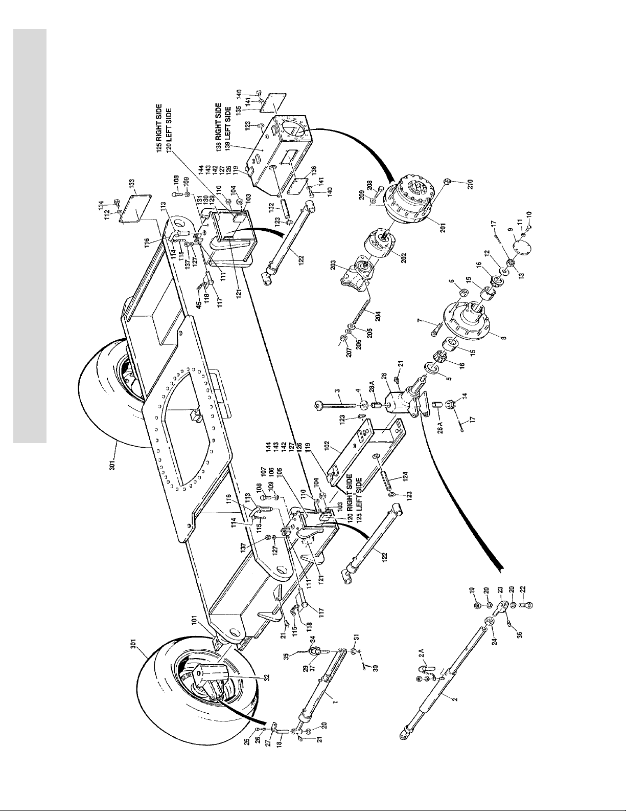
FIGURE 1-1. STEERING AND AXLE/WHEEL DRIVE INSTALLATIONS
1-2 3120801
Page 11

SECTION 1 FRAME
S
FIGURE 1-1. STEERING AND AXLE/WHEEL DRIVE INSTALLATIONS
FIG & ITEM # PART NUMBER DESCRIPTION QTY. REV.
2360280 FRAME WELDMENT Ref.
1281982 STEERING INSTALLATION Ref. F
0239122 Standard Ref. 5
0259555
1 1681934
2 4843050 Tie-Rod Assembly 1
2A 3420620 Pin, Quick Release 1
3 3421553 Kingpin 2
4 4740314 Washer, Thrust 2
5 3960243 Seal, Hub 2
6 3300007 Nut, Wheel 24
7 0630078 Stud, Wheel 24
8 2780159 Hub Assembly (Includes Item 7) 2
9 1120347 Cap, Hub 2
10 0721003 Bolt #10-24NC x 3/8” 8
11 4761000 Lockwasher #10 8
12 4740347 Washer, Hardened 2
13 3323803 Nut, Slotted 1 3/4”-12NF 2
14 3324203 Nut, Slotted 2"-12NF 2
15 0440190 Cup, Bearing 4
16 0440191 Cone, Bearing 4
17 3451012 Pin, Cotter 5/16” x 3" 4
18 3421524 Pin, Steer Cylinder 1
19 3312602 Nut, Jam 1"- 8NC 2
20 4740111 Washer, Thrust 5
21 2160002 Fitting, Grease 3
22 0642644 Bolt 1"-8NCx 5 1/2” 2
23 0560605 Block 2
24 3323002 Nut, Jam 1 1/4” - 12 NF 2
25 0641507 Bolt 5/16”-18NC x 7/8” 2
26 4761500 Lockwasher 5/16” 2
27 3532561 Plate, Retainer 1
28 Spindle (Left Side) Options: 1
4130206 Standard
4130370 Standard (Machines With Tow Bar Package)
28A 0960821 Bushing, Bronze 2
29 3421330 Pin, Clevis (Prior to S/N 33256) 1
3422635 Pin, Clevis (S/N 33256 to Present) 1
See Note
30 3420158 Hairpin 1
31 4712600 Flatwasher 1" 1
32 4130205 Spindle (Right Side) 1
0960821 Bushing, Bronze 2
33 0100011 Loctite #242 (Not Shown) A/R
Standard (Machines with Tow Bar Package) (S/N
47309 to Present)
Steer Cylinder Assembly (See Section 5 for Breakdown)
3421330 Pin (Prior to S/N 33256) (Note Recommend
using 3422635 in place of original 3421330)
Ref. 1
1
E
C
T
I
O
N
1
F
R
A
M
E
3120801 1-3
Page 12

S
SECTION 1 FRAME
E
C
T
I
O
N
1
F
R
A
M
E
FIGURE 1-1. STEERING AND AXLE/WHEEL DRIVE INSTALLATIONS (CONTINUED)
FIG & ITEM # PART NUMBER DESCRIPTION QTY. REV.
34 3760170 Ring, Quick Release 2
35 1260017 Chain 8in/20cm
36 2160001 Fitting, Grease - 90° 2
37 2160003 Fitting, Grease - 45° 1
0239089 AXLES INSTALLATION Ref. 9
101 4843031 Inner Axle Weldment (Front Right Side) 1
102 4843030 Inner Axle Weldment (Front Left Side) 1
103 3972218 Setscrew 3/4”-10NC x 2 1/4” 16
104 3312202 Nut, Jam 3/4”-10NC 16
105 0361632 Bar 2
106 4070576 Shim 1/32” 2
107 4070577 Shim 1/16” 2
108 0642008 Bolt 5/8”-11NC x 1" 8
109 4712000 Flatwasher 5/8” 8
110 3311505 Locknut 5/16”-18NC 12
111 4300032 Stud (Welded on Part) 4
112 4761400 Lockwasher 1/4” 8
113 4843032 Bushing Weldment 4
114 3760106 D-Ring 4
115 1260017 Chain #3 64in/1.6m
116 3421546 Pin, Axle Lock 4
117 3421565 Snap-Pin 4
118 3760170 Ring, Quick Release 4
119 3340527 Wear Pad 4
120 0560674 Block, Axle Shim 8
121 0560673 Block, Axle Shim 2
122 1681964
123 3760140 Ring, Retaining 8
124 3421549 Pin, Attaching (Front Axle Cylinder) 2
125 0560675 Block, Axle Shim 2
126 0641406 Bolt 1/4”-20NC x 3/4” 8
127 4751400 Flatwasher 1/4” 12
128 0100011 Loctite #242 (Not Shown) A/R
129 0361631 Bar, Wear 2
130 4070574 Shim 1/16” 2
131 4070575 Shim 1/32” 2
132 3421548 Pin, Attaching (Rear Axle Cylinder) 2
133 3532592 Plate, Cover 1
134 0641403 Bolt 1/4”-20NC x 5/8” 4
135 3532590 Plate, Cover 2
136 3532591 Plate, Cover 2
137 3300151 Nut, Acorn 4
138 4843028 Inner Axle Weldment (Rear Right Side) 1
139 4843023 Inner Axle Weldment (Rear Left Side) 1
140 0641505 Bolt 5/16”-18NC x 5/8” 16
141 4761500 Lockwasher 5/16” 16
142 4070670 Shim 1/8” A/R
Axle Extension Cylinder Assembly Options (See Section 5 for Breakdown)
2
1-4 3120801
Page 13

SECTION 1 FRAME
S
FIGURE 1-1. STEERING AND AXLE/WHEEL DRIVE INSTALLATIONS (CONTINUED)
FIG & ITEM # PART NUMBER DESCRIPTION QTY. REV.
143 4070672 Shim 1/32” A/R
144 4070674 Shim 1/16” A/R
0239152 WHEEL DRIVE INSTALLATION Ref. 3/B
201 2780155 Hub Assembly (See Figure 1-2 for Breakdown) 2
202 Brake Assembly Options: 2
0920072 Prior to March 1992 (See Figure 1-3 for
Breakdown)
0920084 March 1992 to S/N 33476 (See Figure 1-4 for
Breakdown)
0920110 S/N 33476 to Present (See Figure 1-4 for
Breakdown)
0920119 Optional Replacement (Note: Can be used as
suitable replacement. Requires P/N 4300097
5-1/8” long Stud) (was p/n 0920117)
Note: Repair Kit p/n 7018612 & Mounting Face
Gasket p/n 7000731 are only Service Parts
available for Brake p/ns 0920119 & 0920117.
203 Motor Assembly Options: 2
Use 1001096405 Original Equipment (was p/n 3160132 - See Figure
1-5 for Breakdown)
1001096405 Service Replacement Kit (See Figure 1-6 for
Breakdown)
204 4300092 Stud 1/2”-13NC x 5 1/2” 4
205 4751800 Flatwasher 1/2” 4
206 4761800 Lockwasher 1/2” 4
207 3311801 Nut 1/2”-13NC 4
208 0642216 Bolt 3/4”-10NC x 2" 24
209 4762200 Lockwasher 3/4” Narrow 24
210 3300007 Lugnut 3/4”-16NF 24
E
C
T
I
O
N
1
F
R
A
M
E
TIRE AND WHEEL INSTALLATIONS Ref.
Note: Assemblies may require ballast/foam filling to
manufacturer’s specifications prior to installing on
a machine. Refer to Operation & Safety or Service &
Maintenance Manuals. Purchase individual tire and/
or rim only if able to foam fill tire & wheel assembly,
otherwise, purchase complete assembly.
301 0239344
0253929
0259456
0259442
3120801 1-5
Tire and Wheel Assembly - 15 x 22.5 Foam-Filled (Prior
to April 1993)
Tire and Wheel Assembly - 385/65R22.5 Foam-Filled
(April 1993 to S/N 44997)
Tire and Wheel Assembly - 385/65R22.5 Foam-Filled
L.H. (S/N 44997 to Present)
Tire and Wheel Assembly - 385/65R22.5 Foam-Filled
R.H. (S/N 44997 to Present)
A/R
A/R
2
2
Page 14

S
SECTION 1 FRAME
E
C
T
I
O
N
1
F
R
A
M
E
FIGURE 1-2. DRIVE HUB ASSEMBLY
1-6 3120801
Page 15

SECTION 1 FRAME
S
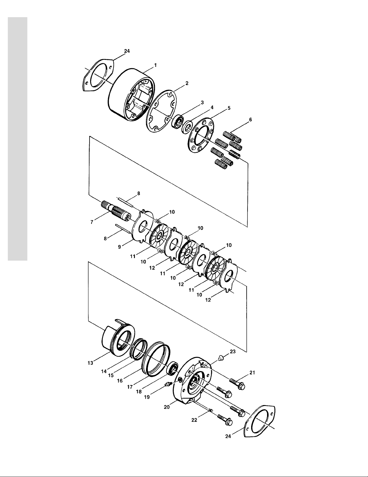
FIGURE 1-2. DRIVE HUB ASSEMBLY
FIG & ITEM # PART NUMBER DESCRIPTION QTY. REV.
2780155 DRIVE HUB ASSEMBLY Ref.
1 7001974 Bolt, Hex Head 16
2 7001975 Bolt, Hex Head Shoulder 4
3 7001976 Lockwasher 20
— — — — — — — — — —
7001965 Cover Assembly 1
4 7001966 Cover 1
5 7001928 Plug, Pipe 1
6 7000243 Plug, Pipe 1
7 7001967 Cap, Cover 1
8 Kit O-Ring 1
9 7001968 Rod, Disconnect 1
10 Kit O-Ring 1
11 7000231 Cap, Disconnect 1
12 7000220 Bolt 4
13 7001963 Gear, Ring 1
14 Kit O-Ring 2
15 7001972 Thrustwasher 4
16 7001973 Bearing, Thrust 2
17 7001971 Gear, Input (Sun Gear) 1
18 7001970 Spacer, Thrust 1
19 7000285 Ring, Retaining 1
20 7001919 Shaft, Input 1
21 7007657 Gear, Internal 1
— — — — — — — — — —
7001910 Carrier Assembly 1
22 7001955 Carrier 1
23 7001959 Shaft, Planet 3
24 7001956 Pin, Roll 3
25 7001962 Ring, Retaining 3
26 7001961 Spacer 3
27 7017003 Gear, Cluster 3
28 7001957 Cup, Bearing 6
29 7001958 Cone, Bearing 6
7007698 Hub and Spindle Assembly 1
30 7007699 Spindle 1
31 Kit Seal 1
32 7001948 Cup, Bearing 2
33 7001947 Cone, Bearing 2
34 7001949 Shim, Bearing 1
35 7001950 Ring, Retaining 1
36 7001951 Hub 1
37 7001928 Plug, Pipe 2
38 7001952 Plug, Magnetic 1
39 7000265 Stud 12
40 7001977 Ring, Keeper 1
41 7000284 Ring, Retaining 1
42 7000282 Washer 2
E
C
T
I
O
N
1
F
R
A
M
E
3120801 1-7
Page 16

S
SECTION 1 FRAME
E
C
T
I
O
N
1
F
R
A
M
E
FIGURE 1-2. DRIVE HUB ASSEMBLY (CONTINUED)
FIG & ITEM # PART NUMBER DESCRIPTION QTY. REV.
43 7000283 Spring 1
44 Not Used
45 7000290 Coupling, Input 1
— — — — — — — — — —
2900560 Seal Kit (Includes Items 8, 10, 14 and 31)
1-8 3120801
Page 17

SECTION 1 FRAME
S
FIGURE 1-2. DRIVE HUB ASSEMBLY (CONTINUED)
FIG & ITEM # PART NUMBER DESCRIPTION QTY. REV.
E
C
T
I
O
N
1
F
R
A
M
E
3120801 1-9
Page 18
S
SECTION 1 FRAME
E
C
T
I
O
N
1
F
R
A
M
E
FIGURE 1-3. DRIVE BRAKE ASSEMBLY - AUSCO
1-10 3120801
Page 19

SECTION 1 FRAME
S
FIGURE 1-3. DRIVE BRAKE ASSEMBLY - AUSCO
FIG & ITEM # PART NUMBER DESCRIPTION QTY. REV.
0920072 DRIVE BRAKE ASSEMBLY - AUSCO Ref. D
1 7003047 Housing 1
2 Kit Gasket 1
3 7003049 Bearing 1
4 Kit Seal, Oil 1
5 7003051 Retainer, Spring 1
6 7003052 Spring, Compression 8
7 7003070 Shaft, Splined 1
8 7000717 Pin, Torque 2
9 7003054 Disc, Primary 1
10 7003006 Spring, Separator 6
11 7003055 Disc, Rotating 3
12 7003056 Disc, Stationary 3
13 7003057 Piston 1
14 Kit Ring, Backup 1
15 Kit O-Ring 1
16 Kit Ring, Backup 1
17 Kit O-Ring 1
18 7000760 Bearing 1
19 7000796 Screw, Bleeder 1
20 7003071 Plate, Power 1
21 7003007 Screw 4
22 7003059 Valve, Pressure 1
23 7000728 Plug 1
24 Kit Gasket 2
— — — — — — — — — —
2900662 Seal Kit (Includes Items 2,4,14,15,16, 17 and 24) 1
7003069 Gasket Kit (Includes Item 24) 1
E
C
T
I
O
N
1
F
R
A
M
E
3120801 1-11
Page 20
S
SECTION 1 FRAME
E
C
T
I
O
N
1
F
R
A
M
E
FIGURE 1-4. DRIVE BRAKE ASSEMBLY - MICO
1-12 3120801
Page 21

SECTION 1 FRAME
S
FIGURE 1-4. DRIVE BRAKE ASSEMBLY - MICO
FIG & ITEM # PART NUMBER DESCRIPTION QTY. REV.
1 Kit Seal, Oil 1
2 Kit Bearing 1
3 7007977 Ring, Retaining 1
4Not Used
5Not Used
6Not Used
7Not Used
8Not Used
9Not Used
10 Not Used
11 Kit Seal, Case 1
12 Not Used
13 7007986 Cover 1
14 Not Used
15 7011716 Ring, Retainer 1
16 Not Used
17 7007987 Pin, Dowel 2
18 Kit Ring, Back-up 1
19 Kit O-Ring 1
20 Kit Ring, Back-up 1
21 Kit O-Ring 1
22 Kit Rotor 2
23 Kit Stator 2
24 Not Used
25 7007924 Plug, Pipe 1
26 and 27 Not Used
28 Kit O-Ring 2
29 7007933 Gasket 2
— — — — — — — — — —
2900766 Seal Kit (Includes Items 1,11,18,19,20,21,28 and 29) 1
2900768 Bearing Kit (Includes Items 1,2,11,28 and 29) 1
E
C
T
I
O
N
1
F
R
A
M
E
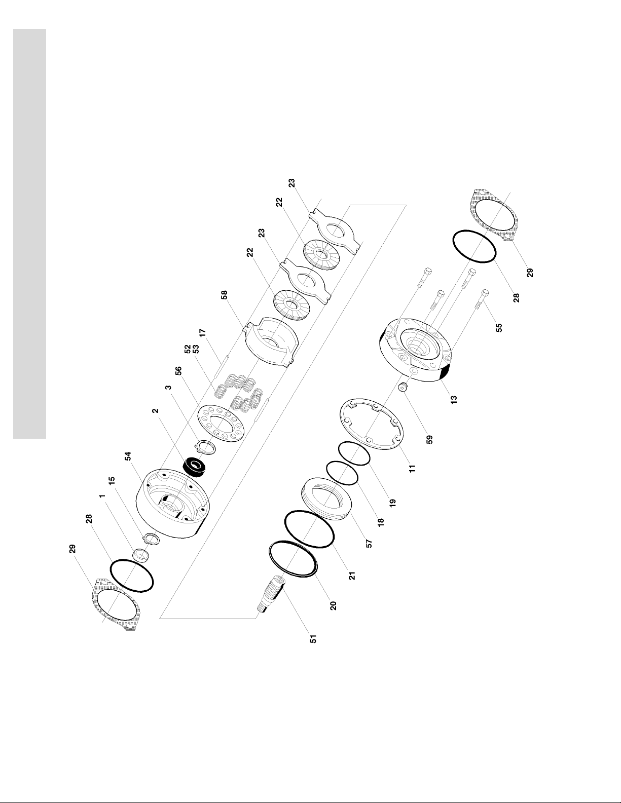
DRIVE BRAKE ASSY - MICO (VARIABLE PARTS)
0920084 Prior To S/N 33476 Ref. A
0920110 S/N 33476 To Present Ref. B
51 7011712 Shaft 1
52 Spring Options: A/R
7007979 Inner Spring - Prior To S/N 33476 6
7007980 Outer Spring - Prior To S/N 33476 6
Not Required S/N 33476 To Present 0
53 Spring Options: A/R
Not Required Prior To S/N 33476 0
7007970 Spring (Red) - S/N 33476 To Present 6
7018602 Spring (Blue) - S/N 33476 To Present 3
54 Housing Options: 1
7011713 Prior To S/N 33476
7018605 S/N 33476 To Present
3120801 1-13
Page 22

S
SECTION 1 FRAME
E
C
T
I
O
N
1
F
R
A
M
E
FIGURE 1-4. DRIVE BRAKE ASSEMBLY - MICO (CONTINUED)
FIG & ITEM # PART NUMBER DESCRIPTION QTY. REV.
55 Bolt, Washer Head Options: 4
7007985 Prior To S/N 33476
7018607 S/N 33476 To Present
56 Guide, Spring Options: 1
7011717 Prior To S/N 33476
7018606 S/N 33476 To Present
57 Piston Options: 1
7007923 Prior To S/N 33476
7018603 S/N 33476 To Present
58 Plate, Return/Separator Assembly Options: 1
7007923 Prior To S/N 33476 Components:
Kit Plate, Return 1
7011715 Separator Assembly 2
7011714 Pin 4
7007983 Separator 2
7018603 S/N 33476 To Present Components:
Kit Plate, Return 1
59 Plug Options: 1
7007914 Bleeder Screw - Prior To S/N 33476
7018609 Plug - S/N 33476 To Present
Lining Kit Options (Includes Items 58, 11, 22, 23, 28
and 29):
2900767 Prior To S/N 33476
7018608 S/N 33476 To Present
1
1-14 3120801
Page 23

SECTION 1 FRAME
S
FIGURE 1-4. DRIVE BRAKE ASSEMBLY - MICO (CONTINUED)
FIG & ITEM # PART NUMBER DESCRIPTION QTY. REV.
E
C
T
I
O
N
1
F
R
A
M
E
3120801 1-15
Page 24

S
SECTION 1 FRAME
E
C
T
I
O
N
1
F
R
A
M
E
FIGURE 1-5. DRIVE MOTOR ASSEMBLY - VICKERS
1-16 3120801
Page 25

SECTION 1 FRAME
S
FIGURE 1-5. DRIVE MOTOR ASSEMBLY - VICKERS
FIG & ITEM # PART NUMBER DESCRIPTION QTY. REV.
3160132 DRIVE MOTOR ASSEMBLY - VICKERS Ref. B
1 7006766 Yoke 1
2 7006767 Roll Pin 1
3 7006768 Spherical Seat 1
4 7006769 Spring Seat 1
5 7006774 Yoke Spring 1
6 7006776 Yoke Stop 1
7 Kit Gasket 1
8 7006786 Housing 1
9 7006787 Washer 6
10 7006788 Screw 6
11 7006789 Screw 4
12 Shim (Included with Item 18) 1
13 7006721 Retaining Ring 1
14 7006796 Shaft 1
15 7006791 Bearing 2
16 7006792 Pintle Bearing 2
17 Kit O-Ring 2
18 7006794 Shim Kit (Includes Item 12) 1
19 7006795 Cover 2
20 7006719 Bearing 1
21 7006797 Piston 1
22 7006798 Piston Rod 1
23 7006703 Plug 1
24 Kit O-Ring 1
25 7009300 Screw 4
26 7009301 Control Block 1
27 Kit Gasket 1
28 Kit O-Ring 1
29 Kit Back-up Ring 1
30 7009305 Retaining Ring 1
31 7009306 Valve Block 1
32 7006706 Pin 1
33 7009307 Pin 2
34 7009308 Shaft 1
35 7006717 Piston and Shoes 9
36 7006716 Shoe Plate 1
37 7006715 Spherical Washer 1
38 7006714 Pin, Retainer 1
39 7006713 Pin 3
40 7006712 Cylinder, Block 1
41 7006711 Spring Washer 1
42 7006710 Spring 1
43 7006709 Spring Washer 1
44 7009309 Retaining Ring 1
45 7006707 Bearing Spacer Kit 1
46 7009310 Wafer Plate 1
47 7006704 Bearing S/A 1
E
C
T
I
O
N
1
F
R
A
M
E
3120801 1-17
Page 26

S
SECTION 1 FRAME
E
C
T
I
O
N
1
F
R
A
M
E
FIGURE 1-5. DRIVE MOTOR ASSEMBLY - VICKERS (CONTINUED)
FIG & ITEM # PART NUMBER DESCRIPTION QTY. REV.
— — — — — — — — — —
2900659 Seal Kit (Includes 7,14,17,24,27,28 and 29) 1
1-18 3120801
Page 27

SECTION 1 FRAME
S
FIGURE 1-5. DRIVE MOTOR ASSEMBLY - VICKERS (CONTINUED)
FIG & ITEM # PART NUMBER DESCRIPTION QTY. REV.
E
C
T
I
O
N
1
F
R
A
M
E
3120801 1-19
Page 28
S
3
41
3
401938
303433
32
313231
18
1
1
4
121310
119161517
14
7
8
6
2
5
5
22
20
21
23
24
25
26
28
27
37
36
35
39
29
100
SECTION 1 FRAME
E
C
T
I
O
N
1
F
R
A
M
E
FIGURE 1-6. DRIVE MOTOR ASSEMBLY - SAUER-DANFOSS
1-20 3120801
Page 29

SECTION 1 FRAME
S
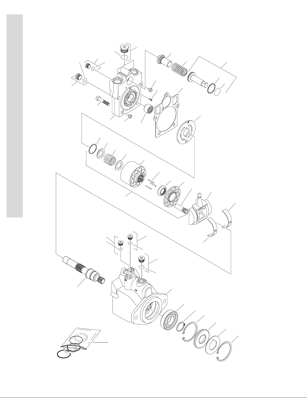
FIGURE 1-6. DRIVE MOTOR ASSEMBLY - SAUER-DANFOSS
FIG & ITEM # PART NUMBER DESCRIPTION QTY. REV.
1001096405 DRIVE MOTOR ASSEMBLY KIT - SAUER-DANFOSS Ref. 2
1001096406 Drive Motor Assembly - Sauer-Danfoss Ref. A
1 7022302 Bearing, Journal 2
2 7007446 Pin 1
3 7007438 Ring, Retaining 2
4 70000794 Swashplate 1
5 Not Available Pin 2
6 Use Item 100 Gasket 1
7 7027740 Cylinder Block Kit (Includes Items 9-17) 1
8 7024862 Plate, Valve 1
9 Use Item 7 Block, Cylinder 1
10 70000856 Guide, Slipper Retainer 1
11 7021275 Pin, Slipper Hold Down 3
12 7024865 Piston Assembly 9
13 70000857 Retainer, Slipper 1
14 7022311 Ring, Retaining 1
15 7024867 Spring 1
16 7024868 Washer 1
17 7022314 Retainer, Spring 1
18 7023910 Shaft 1
19 7007439 Ring, Retaining 1
20 70000795 Cap, End - Axial 1
21 7022368 Screw 5
22 7021249 Bearing, Needle 1
23 7022321 Plug (Includes Item 24) 1
24 7022322 O-Ring 1
25 7007420 Plug (Includes Item 26) 1
26 7021256 O-Ring 1
27 7007419 Plug (Includes Item 28) 2
28 7007418 O-Ring 2
29 Not Available Seat, Spring 1
30 Not Available Housing 1
31 7007420 Plug (Items Item 32) 2
32 7021256 O-Ring 2
33 7022321 Plug (Items Item 34) 1
34 7022322 O-Ring 1
35 7022324 O-Ring 1
36 7022325 Ring, Seal 1
37 7024871 Piston, Servo 1
38 7007437 Bearing 1
39 7022326 Spring 1
40 7007459 Seal, Lip 1
41 7022371 Washer, Support 1
100 7022328 Seal Kit (Includes Items 6,24,26,28,32,34,35,36 and
40)
Adapter Options: Ref.
201 70001098 Adapter 12x16 (Not Shown) 1
202 70001099 Adapter 8x10 (Not Shown) 1
1
E
C
T
I
O
N
1
F
R
A
M
E
3120801 1-21
Page 30

S
SECTION 1 FRAME
E
C
T
I
O
N
1
F
R
A
M
E
FIGURE 1-7. VALVES AND SWITCHES INSTALLATIONS (FRAME MOUNTED)
1-22 3120801
Page 31

SECTION 1 FRAME
S
FIGURE 1-7. VALVES AND SWITCHES INSTALLATIONS (FRAME MOUNTED)
FIG & ITEM # PART NUMBER DESCRIPTION QTY. REV.
0239072
1 4640039 Valve, Selector 1
7006851 O-Ring (Valve Seals) 2
2 0641626 Bolt 3/8”-16NC x 3 1/4" 2
3 4751600 Flatwasher 3/8" 2
4761600 Lockwasher 3/8" 2
4 3311601 Nut 3/8"-16NC 2
5 to 6 Not Used
7 2980089 Lever 1
8 4751400 Flatwasher 1/4" 6
0256611
51 4640986 Valve, Selector 1
51A 7012995 Cartridge Less Coil 2
7012518 Seal Kit - 7012995 Cartridge (1 Per Cartridge) 2
51B 7000645 Coil 2
51C 7017409 Cartridge, Directional 2
7012518 Seal Kit - 7017409 Cartridge (1 Per Cartridge) 2
51D 7011336 Cartridge (Sun) 2
2900770 Seal Kit - 7011336 Cartridge (1 Per Cartridge) 2
52 0641506 Bolt 5/16"-18NC x 3/4" 2
53 4751500 Flatwasher 5/16" 2
54 0100011 Loctite (Not Shown) A/R
55 3539843 Plate, Mounting 1
SELECTOR VALVE INSTALLATION (USED WITHOUT
AXLE JACK OR WITH SINGLE AXLE JACK)
SELECTOR VALVE INSTALLATION (USED WITH DUAL
JACKS)
Ref. B
Ref. 2
E
C
T
I
O
N
1
F
R
A
M
E
0239046 VALVES INSTALLATION Ref. 5
101 4640451 Valve, Counterbalance 1
7010630 Cartridge 2
7011317 Seal Kit - 7010630 Cartridge 2
102 4640260 Valve, Flow Divider 1
Not Available Cartridge (Vickers/Modular Controls Version) 1
7009379 Seal Kit (Vickers/Modular Controls Version) 1
7007321 Cartridge (Fluid Controls Version) 1
7007323 Seal Kit (Fluid Controls Version) 1
103 2220061 Fitting, Adapter 1
104 2180134 Fitting, Straight 1
105 0641626 Bolt 3/8"-16NC x 3 1/4" 2
106 4761600 Lockwasher 3/8" 2
107 3311601 Nut 3/8"-16NC 2
108 4640123 Valve, 2 Speed 1
7012518 Seal Kit (Hydraforce Version) 1
7000558 Seal Kit (FPS Version) 1
7004368 Coil (Hydraforce Version) 1
7006075 Coil (FPS Version) 1
3120801 1-23
Page 32

S
SECTION 1 FRAME
E
C
T
I
O
N
1
F
R
A
M
E
FIGURE 1-7. VALVES AND SWITCHES INSTALLATIONS (FRAME MOUNTED) (CONTINUED)
FIG & ITEM # PART NUMBER DESCRIPTION QTY. REV.
109 0641518 Bolt 5/16"-18NC x 2 1/4" 2
110 4761500 Lockwasher 5/16" 2
111 3311501 Nut 5/16"-18NC 2
0250993 AXLE LIMIT SWITCHES INSTALLATION Ref. 3
201 Not Used
202 3534395 Plate, Switch Mounting 4
203 4360277 Switch, Limit 4
204 4360236 Head, Switch Actuator 4
205 3900168 Bolt, Drilled Head #10-24NC x 1 3/4" 8
206 4920140 Lockwire 4
207 4360237 Arm and Roller 2
208 4360278 Arm and Roller 2
209 4460049 Connector, Strain Relief 4
210 0860037 Box, Electrical 1
3500812 Cover, Electrical Box 1
4460023 Connector, Strain Relief 5
3311401 Nut 1/4"-20NC 2
4761400 Lockwasher 1/4" 2
211 to 215 Not Used
216 1100049 Cam 4
217 4564974 Tube, Cable Carrier 2
0239126 FRAME SHIELDS INSTALLATION Ref. C
301 4060681 Shield (Front) 1
302 4060682 Shield (Rear) 1
303 Not Used
304 4761400 Lockwasher 1/4" 8
305 3300151 Nut, Acorn 1/4"-20NC 8
306 0100011 Loctite #242 (Not Shown) A/R
0256602
401 4843122 Bracket Weldment 2
402 Axle Lift Cylinder Assembly Options: 2
1681991 Prior to S/N 34133 (See Section 5 for Breakdown)
1683596 S/N 34133 to Present (See Section 5 for Breakdown)
403 3421584 Pin 2
404 3450508 Pin, Cotter 4
405 Bolt Options: 4
0641809 Bolt 1/2"-13NC x 1 1/8" (Prior to S/N 34133)
0641844 Bolt 1/2"-13NC x 5 1/8" (S/N 34133 to Present)
406 Hardware Options: 4
4761800 Lockwasher 1/2" (Prior to S/N 34133)
3311805 Locknut 1/2"-13NC (S/N 34133 to Present)
AXLE LIFT CYLINDER INSTALLATION (WITH DUAL
AXLE JACK)
Ref. 6
1-24 3120801
Page 33

SECTION 1 FRAME
S
FIGURE 1-7. VALVES AND SWITCHES INSTALLATIONS (FRAME MOUNTED) (CONTINUED)
FIG & ITEM # PART NUMBER DESCRIPTION QTY. REV.
407 Options: 2
3532839 Plate, Base (Prior to S/N 34133)
3340831 Weldment, Jack Pad (S/N 34133 to Present)
408 Use 4713400 Washer, Spacer (Was P/N 4740243) 4
409 0100011 Loctite #242 (Not Shown) (Prior to S/N 34133) A/R
410 3539843 Plate, Valve Mounting 1
411 to 417 Not used
418 4640987 Valve, Select 1
418A 7012995 Cartridge Less Coil 2
7012518 Seal Kit (1 Per Assembly) 2
418B 7000645 Coil (1 Per Assembly) 2
418C 7017408 Cartridge Less Coil 2
7012967 Seal Kit (1 Per Assembly) 2
418D 7012539 Coil (1 Per Assembly) 2
418E 7012912 Cartridge, Relief 2
7012998 Seal Kit (1 Per Assembly) 2
419 4640967 Valve, 3 Way 2
419A 7012995 Cartridge Less Coil 2
7012518 Seal Kit (1 Per Assembly) 2
419B 7000645 Coil (1 Per Assembly) 2
420 0641414 Bolt 1/4"-20NC x 1 3/4" 4
421 4711400 Flatwasher 1/4" Narrow 4
422 3311405 Locknut 1/4"-20NC 4
423 0641506 Bolt 5/16"-18NC x 3/4" 2
424 4751500 Flatwasher 5/16" 2
425 3539631 Plate, Switch Mounting 2
426 4360314 Switch, Toggle 4
427 0641409 Bolt 1/4"-20NC x 1 1/8" 4
428 4761400 Lockwasher 1/4" 4
429 3311401 Nut 1/4"-20NC 4
430 1703083 Decal 2
E
C
T
I
O
N
1
F
R
A
M
E
0239291
501 4843122 Bracket Weldment 1
502 1681991 Axle Lift Cylinder Assembly (See Section 5 for
503 3421584 Pin 1
504 3450508 Pin, Cotter 2
505 0641809 Bolt 1/2"-13NC x 1 1/8" 4
506 4761800 Lockwasher 1/2" 4
507 3532839 Plate, Base 1
508 4740243 Washer, Spacer 2
509 0100011 Loctite #242 (Not Shown) A/R
510 4640039 Valve, Control 1
7006851 O-Ring (Valve Seals) 2
511 0641632 Bolt 3/8"-16NC x 4" 2
512 4761600 Lockwasher 3/8" 2
513 3311601 Nut 3/8"-16NC 2
3120801 1-25
AXLE LIFT CYLINDER INSTALLATION (WITH SINGLE
AXLE JACK)
Breakdown)
Ref. 9
1
Page 34

S
SECTION 1 FRAME
E
C
T
I
O
N
1
F
R
A
M
E
FIGURE 1-7. VALVES AND SWITCHES INSTALLATIONS (FRAME MOUNTED) (CONTINUED)
FIG & ITEM # PART NUMBER DESCRIPTION QTY. REV.
514 3252453 Nameplate 1
515 2980089 Lever 1
4751400 Flatwasher 1/4" 6
516 4565166 Tube, Spacer 2
1-26 3120801
Page 35

SECTION 1 FRAME
S
FIGURE 1-7. VALVES AND SWITCHES INSTALLATIONS (FRAME MOUNTED) (CONTINUED)
FIG & ITEM # PART NUMBER DESCRIPTION QTY. REV.
E
C
T
I
O
N
1
F
R
A
M
E
3120801 1-27
Page 36

S
SECTION 1 FRAME
E
C
T
I
O
N
1
F
R
A
M
E
FIGURE 1-8. TOW PACKAGE INSTALLATIONS
1-28 3120801
Page 37

SECTION 1 FRAME
S
FIGURE 1-8. TOW PACKAGE INSTALLATIONS
FIG & ITEM # PART NUMBER DESCRIPTION QTY. REV.
0252787 TOW PACKAGE INSTALLATION Ref. 9/G
1 0252788 Steering Link Assembly (Includes Items 201-212) 1
2 3536023 Lug, Steering - Plain (Prior to S/N 47309) 1
3 3536028 Lug, Steering - Tapped (Prior to S/N 47309) 1
4 3536024 Plate, Stop 4
5 3536025 Gusset - Right 1
6 3536026 Gusset - Left 1
7 3536027 Lug - Center 2
8 0251221 Tow Bar Assembly (Includes Items 101-103) 1
9Not Used
10 Hitch Options: 1
2620022 Prior to S/N 31729
2620043 S/N 31729 to Present
11 0630439 Bolt 1"- 8NC x 5" (Grade 8) 1
12 4712600 Flatwasher 1" 2
13 Nut 1"- 8NC Options: 2
3312601 Prior to S/N 33983
3312602 S/N 33983 to Present
14 3420860 Pin 1
15 2880410 Key 1
16 4753000 Flatwasher 1 1/4" 2
17 3323002 Nut, Jam 1 1/4"- 12NF 2
18 0961668 Bushing (Prior to S/N 47309) 3
19 0561022 Block, Stop 2
20 4841055 Mount, Tow Bar 2
21 3420292 Pin, Quick Release 2
22 1260017 Chain
23 Decal - Caution Options: 1
3250840 Prior to May 1994
1702305 May 1994 to Present
24 3250872 Nameplate - Tow Select 1
25 3820001 Rivet 4
26 4640261 Valve, Select 1
27 0900479 Bracket 1
28 0641507 Bolt 5/16"-18NC x 7/8" 2
29 4751500 Flatwasher 5/16" 2
30 4761500 Lockwasher 5/16" 2
31 3421892 Pin, Clevis 1
32 0642644 Bolt 1"- 8NC x 5 1/2" (Prior to S/N 33983) 1
0630439 Bolt 1"- 8NC x 5 (S/N 33983 to S/N 44508) 1
3900146 Bolt 1"- 8NC x 5 (S/N 44508 to Present) 1
16in/41cm
E
C
T
I
O
N
1
F
R
A
M
E
0232121 TOW BAR ASSEMBLY Ref.
101 3420447 Pin, Tow 1
102 4740036 Flatwasher, Special 1
103 3420372 Pin, Cotter 1
3120801 1-29
Page 38

S
SECTION 1 FRAME
E
C
T
I
O
N
1
F
R
A
M
E
FIGURE 1-8. TOW PACKAGE INSTALLATIONS (CONTINUED)
FIG & ITEM # PART NUMBER DESCRIPTION QTY. REV.
0252788 STEERING LINK ASSEMBLY Ref. A
201 4844277 Tube, Steer Link - Outer 1
202 4844276 Tube, Steer Link - Inner 1
203 Not Used
204 Not Used
205 3323002 Nut, Jam 1 1/4"-12NF 2
206 0560605 Block, Tie Rod 2
207 3420620 Pin 1
208 Not Used
209 4761400 Lockwasher 1/4" 1
210 1260017 Chain 6in/15cm
211 3311401 Nut 1/4"-20NC 1
212 2160003 Fitting, Grease - 45° 2
1-30 3120801
Page 39

SECTION 2 TURNTABLE
S
E
TABLE OF CONTENTS
FIGURE DESCRIPTION PAGE
2-1 TURNTABLE, BOOM AND CUTOUT SWITCH INSTALLATIONS
(4620044 Turntable Machines) . . . . . . . . . . . . . . . . . . . . . . . . . . . . . . . . . . . . . . . . . . . . . . . 2-2
2-2 TURNTABLE, BOOM AND CUTOUT SWITCH INSTALLATIONS
(4620078 Turntable Machines) . . . . . . . . . . . . . . . . . . . . . . . . . . . . . . . . . . . . . . . . . . . . . . . 2-6
2-3 CONTROL VALVES AND TILT INDICATOR INSTALLATIONS . . . . . . . . . . . . . . . . . . . . . . . . . 2-10
2-4 CONTROL VALVE ASSEMBLY - VICKERS (Prior to October 1994) . . . . . . . . . . . . . . . . . . . . . 2-14
2-5 CONTROL VALVE ASSEMBLY - VICKERS (October 1994 to Present) . . . . . . . . . . . . . . . . . . . 2-18
2-6 CONTROL VALVE ASSEMBLY - BANG-BANG WITH DUMP SECTION
(Prior to June 1995) . . . . . . . . . . . . . . . . . . . . . . . . . . . . . . . . . . . . . . . . . . . . . . . . . . . . . . . 2-22
2-7 CONTROL VALVE ASSEMBLY - BANG-BANG WITH DUMP SECTION
(June 1995to Present). . . . . . . . . . . . . . . . . . . . . . . . . . . . . . . . . . . . . . . . . . . . . . . . . . . . . . 2-26
2-8 ACCESSORY VALVE ASSEMBLY (Miller) (Machines Built Through 1989) . . . . . . . . . . . . . . . . 2-30
2-9 ACCESSORY VALVE ASSEMBLY (Machines Built 1990 to Present) . . . . . . . . . . . . . . . . . . . . . 2-32
2-10 CONTROL VALVE ASSEMBLY - 1 SECTION BANG-BANG
(100HX+10/110HXER Machines) . . . . . . . . . . . . . . . . . . . . . . . . . . . . . . . . . . . . . . . . . . . . . 2-34
2-11 SWING DRIVE, BEARING AND LOCK INSTALLATIONS . . . . . . . . . . . . . . . . . . . . . . . . . . . . . 2-36
2-12 SWING MOTOR ASSEMBLY - Nichols. . . . . . . . . . . . . . . . . . . . . . . . . . . . . . . . . . . . . . . . . . . . 2-38
2-13 SWING BRAKE ASSEMBLY (Prior to April 1992). . . . . . . . . . . . . . . . . . . . . . . . . . . . . . . . . . . . 2-40
2-14 SWING BRAKE ASSEMBLY (April 1992 to Present) . . . . . . . . . . . . . . . . . . . . . . . . . . . . . . . . . 2-44
2-15 SWING HUB ASSEMBLY . . . . . . . . . . . . . . . . . . . . . . . . . . . . . . . . . . . . . . . . . . . . . . . . . . . . . . 2-48
2-16 ROTARY COUPLING AND COLLECTOR RING ASSEMBLY AND INSTALLATION . . . . . . . . . 2-50
2-17 DEUTZ ENGINE INSTALLATION WITHOUT NOISE REDUCTION
(Built Prior to February 1992) . . . . . . . . . . . . . . . . . . . . . . . . . . . . . . . . . . . . . . . . . . . . . . . . 2-54
2-18 DEUTZ ENGINE INSTALLATION WITH NOISE REDUCTION
(Built February 1992 to Present). . . . . . . . . . . . . . . . . . . . . . . . . . . . . . . . . . . . . . . . . . . . . . 2-60
2-19 ADECO THROTTLE COMPONENTS INSTALLATION - DEUTZ ENGINE MACHINES . . . . . . . 2-68
2-20 GENERATOR INSTALLATION - DEUTZ ENGINE MACHINES . . . . . . . . . . . . . . . . . . . . . . . . . 2-70
2-21 PUMP COUPLING INSTALLATION . . . . . . . . . . . . . . . . . . . . . . . . . . . . . . . . . . . . . . . . . . . . . . 2-72
2-22 MAIN PUMP ASSEMBLY . . . . . . . . . . . . . . . . . . . . . . . . . . . . . . . . . . . . . . . . . . . . . . . . . . . . . . 2-74
2-23 TANKS INSTALLATION. . . . . . . . . . . . . . . . . . . . . . . . . . . . . . . . . . . . . . . . . . . . . . . . . . . . . . . . 2-76
2-24 GROUND CONTROLS INSTALLATION . . . . . . . . . . . . . . . . . . . . . . . . . . . . . . . . . . . . . . . . . . . 2-80
2-25 LOAD MANAGEMENT INSTALLATION . . . . . . . . . . . . . . . . . . . . . . . . . . . . . . . . . . . . . . . . . . . 2-86
2-26 HOODS AND ALARM INSTALLATION (Machines with 4620044 Turntable) . . . . . . . . . . . . . . . 2-88
2-27 HOODS AND ALARM INSTALLATION (Machines with 4620078 Turntable) . . . . . . . . . . . . . . . 2-92
C
T
I
O
N
2
T
U
R
N
T
A
B
L
E
3120801 2-1
Page 40

S
SECTION 2 TURNTABLE
E
C
T
I
O
N
2
T
U
R
N
T
A
B
L
FIGURE 2-1. TURNTABLE, BOOM AND CUTOUT SWITCH INSTALLATIONS (4620044 TURNTABLE MACHINES)
E
2-2 3120801
Page 41

SECTION 2 TURNTABLE
S
FIGURE 2-1. TURNTABLE, BOOM AND CUTOUT SWITCH INSTALLATIONS (4620044 TURNTABLE
MACHINES)
FIG & ITEM # PART NUMBER DESCRIPTION QTY. REV.
4620044 TURNTABLE 1
Note: Used on machines built through May 1992
1 0252852 Boom Pivot Assembly 2
0960594 Bushing, Self-Aligning (1 Per Assembly) 2
2 0961392 Bushing, Bronze (Base Pivot) 2
BOOM AND CYLINDERS INSTALLATION Ref.
101 Boom Assembly (See Section 3 for Breakdown) 1
102 1682034 Lift Cylinder Assembly (See Section 5 for Breakdown)
(Prior to May 1992)
1682587 Lift Cylinder Assembly (See Section 5 for Breakdown)
(May 1992 to Present)
103 Not Used
104 3951814 Setscrew 1/2"-13NC x 1 3/4" 2
105 3311802 Nut, Jam 1/2"-13NC 2
106 2160002 Fitting, Grease 3
107 0681812 Bolt 1/2"-13NC 4
108 4740171 Washer, Special Hardened 4
109 0100019 Loctite #271 (Not Shown) A/R
110 1120368 Cap, Boom Pivot 2
111 Not Used
112 3421555 Pin, Boom Pivot 1
113 to 116 Not Used
117 4300038 Stud (Welded on Part) 1
118 4751500 Flatwasher 5/16" 1
119 4761500 Lockwasher 5/16" 1
120 3311501 Nut 5/16"-18NC 1
121 Not Used
122 Not Used
123 3421676 Pin, Bottom Lift Cylinder 1
124 4712200 Flatwasher 3/4" 2
125 4762200 Lockwasher 3/4" 2
126 0682213 Bolt 3/4"-10NC x 1 5/8" (Grade 8) 2
127 3421678 Pin, Top Lift Cylinder 1
128 4740361 Washer, Special 2
129 3900159 Screw, Countersunk 1/2"-13NC x 3/4" 4
130 0641840 Bolt 1/2"-13NC x 5" 1
131 3311805 Locknut 1/2"-13NC 1
132 2160001 Fitting, Grease - 90° 1
133 4740040 Flatwasher, Special 2
1
1
E
C
T
I
O
N
2
T
U
R
N
T
A
B
L
E
3120801 2-3
Page 42

S
SECTION 2 TURNTABLE
E
C
T
I
O
N
2
T
U
R
N
T
A
B
L
E
FIGURE 2-1. TURNTABLE, BOOM AND CUTOUT SWITCH INSTALLATIONS (4620044 TURNTABLE
MACHINES) (CONTINUED)
FIG & ITEM # PART NUMBER DESCRIPTION QTY. REV.
BOOM INSTALLATION (VARIABLE PARTS) Ref.
0250612 110HX Prior To Early 1990 Ref. —
0251019 110HX Early 1990 To May 1992 Ref. D
0239863 110HXER Prior To Early 1990 Ref. D
0251018 110HXER Early1990 To May 1992 Ref. C
151 Master Cylinder Assembly Options (See Section 5 for
Breakdown):
1681978 110HX
1681580 110HXER
152 Pin Options: 1
3421586 110HX
0236548 110HXER
153 Flatwasher, Special Options: A/R
Not Required 110HX 0
4740006 110HXER 1
154 Bolt 3/8"-16NC x 1" Options: 1
Not Required 110HX
0641608 110HXER
155 Lockwasher 3/8" Options: 3
Not Required 110HX
4761600 110HXER
156 Pin Options: 1
3421561 110HX
3420085 110HXER
157 Pin, Cotter 3/16" x 2 1/2" Options: 2
Not Required 110HX
3450610 110HXER
1
0251007 HORIZONTAL CUTOUT LIMIT SWITCH INSTALLA-
TION (RIGHT SIDE)
201 4360277 Switch, Limit 1
202 4360236 Head, Actuator 1
203 4360278 Roller and Arm 1
204 0560984 Block, Switch Mounting 1
205 3900168 Bolt, Socket Head #10-24NC Special 2
206 4920140 Lockwire 1
207 4460052 Connector, Strain Relief 1
208 1100048 Cam 1
209 1120372 Cap 1
210 0681812 Bolt 1/2"-13NC x 1 1/2" (Grade 8) 2
211 4740171 Washer, Special Hardened 2
212 Not Used
213 0641408 Bolt 1/4"-20NC x 1" 2
214 4761400 Lockwasher 1/4" 2
— — — — — — — — — —
0100019 Loctite #271 A/R
2-4 3120801
Ref. 2/B
Page 43

SECTION 2 TURNTABLE
S
FIGURE 2-1. TURNTABLE, BOOM AND CUTOUT SWITCH INSTALLATIONS (4620044 TURNTABLE
MACHINES) (CONTINUED)
FIG & ITEM # PART NUMBER DESCRIPTION QTY. REV.
0251006 8 METER CUTOUT LIMIT SWITCH INSTALLATION
(DUTCH AND GERMAN SPECS PRIOR TO S/N 28224)
(LEFT SIDE)
301 4360277 Switch, Limit 1
302 4360236 Head, Actuator 1
303 4360278 Roller and Arm 1
304 0560984 Block, Switch Mounting 1
305 3900168 Bolt, Socket Head #10-24NC Special 2
306 4920140 Lockwire 1
307 4460052 Connector, Strain Relief 1
308 1100047 Cam 1
309 1120372 Cap 1
310 0681812 Bolt 1/2"-13NC x 1 1/2" (Grade 8) 2
311 4740171 Washer, Special Hardened 2
312 Not Used
313 0641408 Bolt 1/4"-20NC x 1" 2
314 4761400 Lockwasher 1/4" 2
— — — — — — — — — —
0100019 Loctite #271 A/R
Ref. B
E
C
T
I
O
N
2
T
U
R
N
T
A
B
L
LUBE LINES INSTALLATION Ref.
0239843 110HX & 100HX Ref. A
0239844 110HXER Ref. 3
401 2160002 Fitting, Grease 3
402 2220001 Fitting 3
403 to 404 Not Used
405 2750807 Hose 1
406 2200261 Fitting, Nipple 2
407 2750527 Hose 2
408 2220063 Fitting 3
409 4300031 Stud (Welded on Part) 1
410 4761400 Lockwasher 1/4" 1
411 3311401 Nut 1/4"-20NC 1
412 1320040 Clamp, Insulated 1
413 to 450 Not Used
451 Hose Options: 1
2750528 110HX & 100HX
2751032 110HXER
452 Hose Options: 1
2750529 110HX & 100HX
2750528 110HXER
E
3120801 2-5
Page 44

S
SECTION 2 TURNTABLE
E
C
T
I
O
N
2
T
U
R
N
T
A
B
L
FIGURE 2-2. TURNTABLE, BOOM AND CUTOUT SWITCH INSTALLATIONS (4620078 TURNTABLE MACHINES)
E
2-6 3120801
Page 45

SECTION 2 TURNTABLE
S
FIGURE 2-2. TURNTABLE, BOOM AND CUTOUT SWITCH INSTALLATIONS (4620078 TURNTABLE
MACHINES)
FIG & ITEM # PART NUMBER DESCRIPTION QTY. REV.
4620078 TURNTABLE 1
Note: Used on machines built May 1992 to Present.
1 0252852 Boom Pivot Assembly 2
0960594 Bushing, Self-Aligning (1 Per Assembly) 2
2 0961392 Bushing, Bronze (Base Pivot) 2
BOOM AND CYLINDERS INSTALLATIONS Ref.
0252921 100HX Standard Machine Ref. 5
0252923 100HX Machine with Chip Covers Ref. 5
0252916 110HX Standard Machine Ref. 4
0252919 110HX Machine with Chip Covers Ref. 4
0252855/0252857
0252934/0252930
101 Boom Assembly (See Section 3 for Breakdown) 1
102 1682630 Lift Cylinder Assembly (See Section 5 for Break-
103 Not Used
104 3952014 Setscrew 5/8"-11NC x 1 3/4" 2
105 3312002 Nut, Jam 5/8"-11NC 2
106 2160002 Fitting, Grease 3
107 0681812 Bolt 1/2"-13NC 4
108 4740171 Washer, Special Hardened 4
109 0100019 Loctite #271 (Not Shown) A/R
110 1120368 Cap, Boom Pivot 2
111 Not Used
112 3421555 Pin, Boom Pivot 1
113 to 116 Not Used
117 4300034 Stud (Welded on Part) 1
118 4751600 Flatwasher 3/8" 1
119 4761600 Lockwasher 3/8" 1
120 3311601 Nut 3/8"-16NC 1
121 to 122 Not Used
123 3421676 Pin, Bottom Lift Cylinder 1
124 4712200 Flatwasher 3/4" 2
125 4762200 Lockwasher 3/4" 2
126 0682213 Bolt 3/4"-10NC x 1 5/8" (Grade 8) 2
127 3421678 Pin, Top Lift Cylinder 1
128 4740361 Washer, Special 2
129 3900159 Screw, Countersunk 1/2"-13NC x 3/4" 4
130 0641840 Bolt 1/2"-13NC x 5" 1
131 3311805 Locknut 1/2"-13NC 1
132 2160001 Fitting, Grease - 90° 1
133 4740040 Flatwasher, Special 2
134 to 150 Not Used
110HXER & 110HX+10 Standard Machine Ref. 2/C
110HXER & 110HX+10 Machine withChip Covers Ref. 2/C
1
down)
E
C
T
I
O
N
2
T
U
R
N
T
A
B
L
E
3120801 2-7
Page 46

S
SECTION 2 TURNTABLE
E
C
T
I
O
N
2
T
U
R
N
T
A
B
L
E
FIGURE 2-2. TURNTABLE, BOOM AND CUTOUT SWITCH INSTALLATIONS (4620078 TURNTABLE
MACHINES) (CONTINUED)
FIG & ITEM # PART NUMBER DESCRIPTION QTY. REV.
151 Master Cylinder Assembly Options (See Section 5 for
Breakdown):
1681978 100HX & 110HX
1681580 110HX+10 & 110HXER
152 Pin Options: 1
3421586 100HX & 110HX
0236548 110HX+10 & 110HXER
153 Flatwasher, Special Options: A/R
Not Required 100HX & 110HX 0
4740006 110HX+10 & 110HXER 1
154 Bolt 3/8"-16NC x 1" Options: 1
Not Required 100HX & 110HX
0641608 110HX+10 & 110HXER
155 Lockwasher 3/8" Options: 3
Not Required 100HX & 110HX
4761600 110HX+10 & 110HXER
156 Pin Options: 1
3422068 100HX & 110HX
3420085 110HX+10 & 110HXER
157 Pin, Cotter 3/16" x 2 1/2" Options: 2
Not Required 100HX & 110HX
3450610 110HX+10 & 110HXER
1
0251007 HORIZONTAL CUTOUT LIMIT SWITCH
INSTALLATION (RIGHT SIDE)
201 4360277 Switch, Limit 1
202 4360236 Head, Actuator 1
203 4360278 Roller and Arm 1
204 0560984 Block, Switch Mounting 1
205 3900168 Bolt, Socket Head #10-24NC Special 2
206 4920140 Lockwire 1
207 4460052 Connector, Strain Relief 1
208 1100048 Cam 1
209 1120372 Cap 1
210 0681812 Bolt 1/2"-13NC x 1 1/2" (Grade 8) 2
211 4740171 Washer, Special Hardened 2
212 Not Used
213 0641408 Bolt 1/4"-20NC x 1" 2
214 4761400 Lockwasher 1/4" 2
— — — — — — — — — —
0100019 Loctite #271 A/R
Ref. 2
2-8 3120801
Page 47

SECTION 2 TURNTABLE
S
FIGURE 2-2. TURNTABLE, BOOM AND CUTOUT SWITCH INSTALLATIONS (4620078 TURNTABLE
MACHINES) (CONTINUED)
FIG & ITEM # PART NUMBER DESCRIPTION QTY. REV.
0251006 8 METER CUTOUT LIMIT SWITCH INSTALLATION
(DUTCH AND GERMAN SPECS PRIOR TO S/N 28224)
(LEFT SIDE)
301 4360277 Switch, Limit 1
302 4360236 Head, Actuator 1
303 4360278 Roller and Arm 1
304 0560984 Block, Switch Mounting 1
305 3900168 Bolt, Socket Head #10-24NC Special 2
306 4920140 Lockwire 1
307 4460052 Connector, Strain Relief 1
308 1100047 Cam 1
309 1120372 Cap 1
310 0681812 Bolt 1/2"-13NC x 1 1/2" (Grade 8) 2
311 4740171 Washer, Special Hardened 2
312 Not Used
313 0641408 Bolt 1/4"-20NC x 1" 2
314 4761400 Lockwasher 1/4" 2
— — — — — — — — — —
0100019 Loctite #271 A/R
Ref.
E
C
T
I
O
N
2
T
U
R
N
T
A
B
L
LUBE LINES INSTALLATION Ref.
0239843 110HX & 100HX Ref. A
0239844 110HXER Ref. 3
401 2160002 Fitting, Grease 3
402 2220001 Fitting 3
403 to 404 Not Used
405 2750807 Hose 1
406 2200261 Fitting, Nipple 2
407 2750527 Hose 2
408 2220063 Fitting 3
409 4300031 Stud (Welded on Part) 1
410 4761400 Lockwasher 1/4" 1
411 3311401 Nut 1/4"-20NC 1
412 1320040 Clamp, Insulated 1
413 to 450 Not Used
451 Hose Options: 1
2750528 110HX & 100HX
2751032 110HXER
452 Hose Options: 1
2750529 110HX & 100HX
2750528 110HXER
E
3120801 2-9
Page 48

S
SECTION 2 TURNTABLE
E
C
T
I
O
N
2
T
U
R
N
T
A
B
L
FIGURE 2-3. CONTROL VALVES AND TILT INDICATOR INSTALLATIONS
E
2-10 3120801
Page 49

SECTION 2 TURNTABLE
S
FIGURE 2-3. CONTROL VALVES AND TILT INDICATOR INSTALLATIONS
FIG & ITEM # PART NUMBER DESCRIPTION QTY. REV.
CONTROL VALVES INSTALLATION Ref.
0239913 4620044 Turntable Machines Built Prior To May
1990
0251093 4620044 Turntable Machines Built May 1990 To May
1992
0254061 4620078 Turntable Machines Ref. 6
1 Control Valve Assembly (Vickers) Options: 1
4640524 Prior to October 1994 (See Figure 2-4 for
Breakdown)
4640914 October 1994 to Present (See Figure 2-5 for
Breakdown)
2 Accessory Valve Options:
2A 4640535 Accessory Valve Assembly (Machines Built
Through 1989) (See Figure 2-8 for Breakdown)
Note: 4640535 Accessory Valve is no longer
available as a complete assembly. See Figure
2-8 for Individual parts.
2B 4640580 Accessory Valve Assembly (Machines built 1990
to
September 1991) (See Figure 2-9 for Breakdown)
Note: 4640580 Accessory Valve is no longer
available as a complete assembly. See Figure
2-9 for Individual parts.
2B 4640716 Accessory Valve Assembly (Machines Built Sep-
tember 1991 to Present) (See Figure 2-9 for
Breakdown)
Note: Complete 4640716 Valves are available.
See Figure 2-9 for Individual parts.
3 4640360 Dump Valve Assembly 1
7009745 Coil (Vickers/Modular Controls Version) 1
7004289 Solenoid Cartridge Less Coil (Vickers/Modular
Controls Version)
7003635 Check Valve Cartridge (Vickers/Modular Controls
Vers ion)
7004368 Coil (Hydraforce Version) 1
7012910 Solenoid Cartridge Less Coil (1989 to Present)
(Hydraforce Version)
7010635 Solenoid Cartridge Less Coil (Prior to 1989)
(Hydraforce Version)
7009798 Check Valve Cartridge (Hydraforce Version) 1
4 Control Valve Assembly (Bang-Bang) Options: 1
4640246 Prior to June 1995 (See Figure 2-6 for Breakdown)
4640941 June 1995 to Present (See Figure 2-7 for
Breakdown)
5Not Used
6 0641708 Bolt 7/16"-14NC x 1" 3
7 4761700 Lockwasher 7/16" 3
8 4300033 Stud (Welded on Part) 2
9 4751400 Flatwasher 1/4" A/R
10 4761400 Lockwasher 1/4" A/R
11 3311401 Nut 1/4"-20NC A/R
Ref. E
Ref. C
1
1
1
1
1
1
1
E
C
T
I
O
N
2
T
U
R
N
T
A
B
L
E
3120801 2-11
Page 50

S
SECTION 2 TURNTABLE
E
C
T
I
O
N
2
T
U
R
N
T
A
B
L
E
FIGURE 2-3. CONTROL VALVES AND TILT INDICATOR INSTALLATIONS (CONTINUED)
FIG & ITEM # PART NUMBER DESCRIPTION QTY. REV.
12 0641526 Bolt 5/16"-18NC x 3 1/4" 2
13 4300038 Stud (Welded on Part) 5
14 4751500 Flatwasher 5/16" 9
15 3311501 Nut 5/16"-18NC 11
16 0901399 Bracket 1
17 4761500 Lockwasher 5/16" 9
18 0641616 Bolt 3/8"-16NC x 2" 4
19 4751600 Flatwasher 3/8" 4
20 4761600 Lockwasher 3/8" 4
21 3311601 Nut 3/8"-16NC 4
22 0140001 Horn 1
23 0641418 Bolt 1/4"-20NC x 2 1/4" 2
24 4751600 Flatwasher 3/8" 3
25 1320041 Clamp 1
26 0641408 Bolt 1/4"-20NC x 1" 1
27 4060808 Flex-Guard 7.5ft/2.3m
28 Not Used
29 4300042 Stud (Welded on Part) A/R
30 to 50 Not Used
51 Dump Valve Assembly Options: 1
4620044 Turntable Machine Built Prior to May
1990 Components:
4640513 Dump Valve Assembly 1
7003640 Coil (Modular Controls Version) A/R
7004289 Cartridge Less Coil (Modular Controls Ver-
sion)
2900503 Seal Kit (Modular Controls Version) A/R
7000645 Coil (Hydraforce Version) A/R
7012910 Cartridge Less Coil (Hydraforce Version) A/R
2900756 Seal Kit (Hydraforce Version) A/R
7022390 Nut (Attachs Coil to Cartridge) 1
4620044 Turntable Machine Built May 1990 to May
1992 Components:
4640543 Dump Valve Assembly 1
7009745 Coil (Modular Controls Version) A/R
7004368 Coil (Hydraforce Version) A/R
4620078 Turntable Machine Components:
4640543 Dump Valve Assembly 1
7009745 Coil (Modular Controls Version) A/R
7004368 Coil (Hydraforce Version) A/R
52 Relief Valve Assembly Options: 1
Not Required 4620044 Turntable Machines
4640839 4620078 Turntable Machines
7012945 Cartridge, Replacement 2
A/R
2-12 3120801
Page 51

SECTION 2 TURNTABLE
S
FIGURE 2-3. CONTROL VALVES AND TILT INDICATOR INSTALLATIONS (CONTINUED)
FIG & ITEM # PART NUMBER DESCRIPTION QTY. REV.
EXTEND-A-REACH VALVE INSTALLATION (110HXER
& 100HX+10 ONLY)
0239155 Prior To December 1989 Ref. —
0250618 December 1989 To Present Ref. 3
101 4640519 Control Valve Assembly (See Figure 2-10 for
Breakdown)
102 4300038 Stud (Welded on Part) 2
103 4761500 Lockwasher 5/16" 4
104 3311501 Nut 5/16"-18NC 6
105 4300070 Stud (Welded on Part) 2
106 4751500 Flatwasher 5/16" 6
0251088 TILT INDICATOR INSTALLATION Ref. 4
201 4360280 Sensor, Level (3°) 1
202 2820022 Tubing, Vinyl (Not Shown) A/R
203 4360171 Sensor, Level (5°) 1
204 4300106 Stud, Grooved (Not Shown) 2
Ref.
1
E
C
T
I
O
N
2
T
U
R
N
T
A
B
L
E
3120801 2-13
Page 52

S
SECTION 2 TURNTABLE
E
C
T
I
O
N
2
T
U
R
N
T
A
B
L
FIGURE 2-4. CONTROL VALVES ASSEMBLY (VICKERS) (PRIOR TO OCTOBER
1994)
E
2-14 3120801
Page 53

SECTION 2 TURNTABLE
S
FIGURE 2-4. CONTROL VALVES ASSEMBLY (VICKERS) (PRIOR TO OCTOBER 1994)
FIG & ITEM # PART NUMBER DESCRIPTION QTY. REV.
1 7006747 Inlet Body 1
2 7006725 Setscrew 1
3 7006733 Plug 1
4 Kit O-Ring 5
5 Kit O-Ring 5
6 Kit O-Ring 5
7 7009350 Working Section - Complete (Drive) (4 Section) 1
8 7006762 Working Section - Complete (Lift) 1
9 7009351 Working Section - Complete (Telescope) 1
10 7006763 Working Section - Complete (Swing) 1
11 Use 7012325 Nut, Retaining (was p/n 7009317) 2
12 Kit O-Ring 2
13 7009316 Core Tube (Includes O-Ring) 2
14 7009315 Coil and Frame 2
15 7009319 Pin 2
16 Kit O-Ring 2
17 7006744 Spool 2
18 7006726 Plug, Torque 2
19 Kit O-Ring 2
20 7006728 Shim Kit 2
21 7006729 Spring 2
22 7006730 Poppet 2
23 7006731 Ball 2
24 7006745 Screw 8
25 Cap, End (Not Sold Separately) 2
26 7006746 Ball 2
27 Kit O-Ring 2
28 7009323 Plug 2
29 Kit Gasket 2
30 7009324 Spring 2
31 7009325 Retainer 2
32 Spool (Not Sold Separately) 1
33 7006757 Seat 2
34 Kit Ring, Back-Up 2
35 Kit O-Ring 2
36 7006732 Servo Stem Assembly 2
37 7006737 Poppet 2
38 7009321 Retainer (13/16"-2.1cm Length) (Design A) 1
7009363 Retainer (1 3/16"-3cm Length) (Design B) 1
Not Required Retainer (Design C)
Kit O-Ring 1
39 7006752 Retainer 2
40 Kit Ring, Back-Up 2
41 Kit O-Ring 2
42 7006773 Spring 2
43 7006756 Poppet 2
44 7006771 Plug, Torque 1
45 Kit O-Ring 1
E
C
T
I
O
N
2
T
U
R
N
T
A
B
L
E
3120801 2-15
Page 54

S
SECTION 2 TURNTABLE
E
C
T
I
O
N
2
T
U
R
N
T
A
B
L
FIGURE 2-4. CONTROL VALVES ASSEMBLY (VICKERS) (PRIOR TO OCTOBER 1994)
(CONTINUED)
FIG & ITEM # PART NUMBER DESCRIPTION QTY. REV.
46 7006761 Ball (Design A - All Sections Except Swing) 2
7006761 Ball (Design A - Swing Section) 1
7006761 Ball (Design B - All Sections) 2
7009369 Poppet (Design C - All Sections) 2
7009368 Spring (Design C - All Sections) 1
47 7006777 Pin, Solid (Design A - Swing Section Only) 1
Not Required Pin, Solid (Design B and Design C)
48 7006780 Cover End 1
49 7006778 Plug, Torque 1
50 Kit O-Ring 1
51 7009329 Rod, Tie 3
52 7006782 Nut 6
7009330 Seal Kit (Includes Items 4, 5, 6, 12, 16, 27, 34, 35, 38,
40,41,45, 50 and Servo Stem O-Rings)
7009395 Seal Kit - Valve Face (Includes Items 4,5 and 6) 5
4
E
2-16 3120801
Page 55

SECTION 2 TURNTABLE
S
FIGURE 2-4. CONTROL VALVES ASSEMBLY (VICKERS) (PRIOR TO OCTOBER 1994)
(CONTINUED)
FIG & ITEM # PART NUMBER DESCRIPTION QTY. REV.
E
C
T
I
O
N
2
T
U
R
N
T
A
B
L
E
3120801 2-17
Page 56

S
SECTION 2 TURNTABLE
E
C
T
I
O
N
2
T
U
R
N
T
A
B
L
FIGURE 2-5. CONTROL VALVES ASSEMBLY (VICKERS) (OCTOBER 1994 TO PRESENT)
E
2-18 3120801
Page 57

SECTION 2 TURNTABLE
S
FIGURE 2-5. CONTROL VALVES ASSEMBLY (VICKERS) (OCTOBER 1994 TO PRESENT)
FIG & ITEM # PART NUMBER DESCRIPTION QTY. REV.
4640914 VICKERS VALVE ASSEMBLY - 4 SECTION Ref. —
Inlet Section Ref.
1 7006724 Inlet Body 1
2 7006733 Plug 1
3 Kit O-Ring 1
4 Kit O-Ring 1
5 Kit O-Ring 1
6 7006725 Setscrew 1
Working Sections (Standard Parts) Ref.
100 Kit Cap (2 Per Section) A/R
101 7012319 Screw (2 Per Section) A/R
102 Kit Nut (2 Per Section) A/R
103 Kit Plug (2 Per Section) A/R
104 Kit Packing (2 Per Section) A/R
105 7012322 Packing (2 Per Section) A/R
106 Kit Piston (2 Per Section) A/R
107 Kit Spring (2 Per Section) A/R
108 7006730 Poppet (2 Per Section) A/R
109 7012325 Nut, Retaining (2 Per Section) A/R
110 7012339 Coil (2 Per Section) A/R
111 7009319 Pin (2 Per Section) A/R
112 7012326 Core Tube Sub Assembly (2 Per Section) A/R
113 7012327 Spool A/R
114 7006745 Screw (8 Per Section) A/R
115 7006731 Ball A/R
116 7006748 Gasket A/R
117 7006746 Ball A/R
118 7009323 Plug (2 Per Section) A/R
119 7012330 Shim (A/R Per Section) A/R
120 7012329 Retainer (2 Per Section) A/R
121 7012328 Shim (A/R Per Section) A/R
122 7009324 Spring (2 Per Section) A/R
123 7009320 Stem Servo Sub Assembly (2 Per Section) A/R
124 7006737 Poppet (2 Per Section) A/R
125 7006757 Seat (2 Per Section) A/R
126 Not Used
127 7006773 Spring (2 Per Section) A/R
128 Kit O-Ring (2 Per Section) A/R
129 Kit Back-up (2 Per Section) A/R
130 7009398 Retainer (2 Per Section) A/R
131 Kit Back-up Ring (2 Per Section) A/R
132 Kit O-Ring (2 per Section) A/R
133 7012333 Load Sense (2 Per Section) A/R
134 Kit O-Ring (2 Per Section) A/R
135 Kit O-Ring (2 Per Section) A/R
136 Kit O-Ring (5 Per Section) A/R
137 Kit O-Ring (2 Per Section) A/R
138 Not Serviced Cap, End (2 Per Section) A/R
E
C
T
I
O
N
2
T
U
R
N
T
A
B
L
E
3120801 2-19
Page 58

S
SECTION 2 TURNTABLE
E
C
T
I
O
N
2
T
U
R
N
T
A
B
L
E
FIGURE 2-5. CONTROL VALVES ASSEMBLY (VICKERS) (OCTOBER 1994 TO PRESENT)
FIG & ITEM # PART NUMBER DESCRIPTION QTY. REV.
— — — — — — — — — —
7009330 Seal Kit (1 Per Section) A/R
7012383 Piston/Spring Kit (Includes 1 each of 100, 102, 103,
106 and 107) (2 per Section)
150 WORKING SECTION (VARIABLE PARTS)
7012332 Drive Section Ref.
7012334 Lift & Telescope Section Ref.
7012335 Swing Section Ref.
151 Spool Options: 1
7012331 Drive Section
7012331 Lift & Telescope Section
7012335 Swing Section
152 Poppet Options: A/R
7009399 Drive Section 2
7009397 Lift & Telescope Section (2 Per Spool) A/R
7009399 Swing Section 2
153 Piston Options: A/R
Not Required Drive Section 2
Not Required Lift & Telescope Section (2 Per Spool) A/R
7012300 Swing Section 2
A/R
OUTLET SECTION Ref.
201 7006782 Nut 6
202 7009361 Rod, Tie 3
203 7012337 Cover End 1
204 Kit O-Ring 2
205 7006778 Plug 2
206 7012338 Setscrew Orifice Sub-Assembly 1
207 Kit O-Ring 1
208 7012336 Plug 1
209 7006770 O-Ring 1
2-20 3120801
Page 59

SECTION 2 TURNTABLE
S
FIGURE 2-5. CONTROL VALVES ASSEMBLY (VICKERS) (OCTOBER 1994 TO PRESENT)
FIG & ITEM # PART NUMBER DESCRIPTION QTY. REV.
E
C
T
I
O
N
2
T
U
R
N
T
A
B
L
E
3120801 2-21
Page 60

S
SECTION 2 TURNTABLE
E
C
T
I
O
N
2
T
U
R
N
T
A
B
L
FIGURE 2-6. CONTROL VALVE ASSEMBLY - BANG-BANG WITH DUMP SECTION (PRIOR TO JUNE 1995)
E
2-22 3120801
Page 61

SECTION 2 TURNTABLE
S
FIGURE 2-6. CONTROL VALVE ASSEMBLY - BANG-BANG WITH DUMP SECTION (PRIOR TO JUNE
1995)
FIG & ITEM # PART NUMBER DESCRIPTION QTY. REV.
4640246 VALVE ASSEMBLY - 3 SECTION Ref. A
1 7002304 DUMP SECTION Ref.
Solenoid Assembly
2 7004823 Seat 1
7002378 O-Ring 1
3 7002229 Ball 1
Guide Tube Assembly 1
4 7004822 Cone, Female 1
7004840 O-Ring 1
5 7002346 Pin, Push 1
6 7004839 Plunger 1
7 7004838 Tube, Guide 1
8 7004841 Pin, Push 1
7002342 O-Ring 1
9 7002340 Guide, External Push Pin 1
7002337 O-Ring 1
10 7004834 Sleeve, Inner Flux 1
11 7002334 Spring 1
12 7004835 Sleeve, Outer Flux 1
13 7000417 Coil 1
14 7004836 Case, Solenoid 1
15 7002338 Plate, End 1
7002327 Nameplate 1
16 7004837 Screw 4
17 7002322 Seat 1
7004826 O-Ring 1
Main Relief (Poppet) Valve 1
18 7002321 Case, Poppet 1
19 7002328 Spring 1
20 7002294 Poppet 1
21 7002320 Seat, Adjustable 1
7004842 O-Ring 1
22 7002329 Spring 1
23 7002323 Plug 1
7000102 O-Ring 1
24 7002326 Orifice 1
25 7002324 Plug 1
E
C
T
I
O
N
2
T
U
R
N
T
A
B
L
E
WORKING SECTIONS (STANDARD PARTS) Ref.
40 7004859 Solenoid Assembly (2 Per Section) (Includes Items
43-56)
41 7002274 Washer (7002315,7002316,7002317 Sections)
(2 Per Section)
7003825 Washer (7003855 Sections) (2 Per Section) A/R
42 7002348 Spring (2 Per Section) A/R
3120801 2-23
A/R
A/R
Page 62

S
SECTION 2 TURNTABLE
E
C
T
I
O
N
2
T
U
R
N
T
A
B
L
FIGURE 2-6. CONTROL VALVE ASSEMBLY - BANG-BANG WITH DUMP SECTION (PRIOR TO JUNE
1995) (CONTINUED)
FIG & ITEM # PART NUMBER DESCRIPTION QTY. REV.
43 7002305 Guide Tube Assembly (1 Per Solenoid Assem-
bly)
44 7002345 Cone, Female (1 Per Solenoid Assembly) A/R
Kit O-Ring (1 Per Solenoid Assembly) A/R
Kit O-Ring (1 Per Solenoid Assembly) A/R
45 7002346 Pin, Push (1 Per Solenoid Assembly) A/R
46 7002344 Plunger (1 Per Solenoid Assembly) A/R
47 7000470 Tube, Guide (1 Per Solenoid Assembly) A/R
48 7002341 Pin, Actuator (1 Per Solenoid Assembly) A/R
Kit Ring, Quad (1 Per Solenoid Assembly) A/R
49 7002340 Guide, External Push Pin (1 Per Solenoid
Assembly)
Kit O-Ring (1 Per Solenoid Assembly) A/R
50 7002333 Sleeve, Inner Flux (1 Per Solenoid Assembly) A/R
51 7002334 Spring (1 Per Solenoid Assembly) A/R
52 7002336 Sleeve, Outer Flux (1 Per Solenoid Assembly) A/R
53 7000418 Coil (1 Per Solenoid Assembly) A/R
54 7002335 Case, Solenoid (1 Per Solenoid Assembly) A/R
55 7002338 Plate, End (1 Per Solenoid Assembly) A/R
56 7002339 Screw (4 Per Solenoid Assembly) A/R
A/R
A/R
E
WORKING SECTION (VARIABLE PARTS) Ref.
Note: Complete Sections listed below include
items 40-56 and relief valve assembly when
equipped
101 7002315 Section #1 - Steer/Tele 1
102 7002316 Section #2 - Level 1
103 7002315 Section #3 - Steer/Tele 1
104 Not Required Section #4 0
105 Relief Valve Options: A/R
7000468 Crossover Relief Valve Assembly (Due to vari-
ous suppliers, internal components are no
longer field serviceable)
7002262 Dual Pilot Check Valve Assembly (Due to vari-
ous suppliers, internal components are no
longer field serviceable)
— — — — — — — — — —
7000414 Seal Kit - Working Section 4
7000413 Seal Kit - Dump Section 1
A/R
2-24 3120801
Page 63

SECTION 2 TURNTABLE
S
FIGURE 2-6. CONTROL VALVE ASSEMBLY - BANG-BANG WITH DUMP SECTION (PRIOR TO JUNE
1995) (CONTINUED)
FIG & ITEM # PART NUMBER DESCRIPTION QTY. REV.
E
C
T
I
O
N
2
T
U
R
N
T
A
B
L
E
3120801 2-25
Page 64

S
SECTION 2 TURNTABLE
E
C
T
I
O
N
2
T
U
R
N
T
A
B
L
FIGURE 2-7. CONTROL VALVE ASSEMBLY - BANG-BANG WITH DUMP SECTION (JUNE 1995 TO PRESENT)
E
2-26 3120801
Page 65

SECTION 2 TURNTABLE
S
FIGURE 2-7. CONTROL VALVE ASSEMBLY - BANG-BANG WITH DUMP SECTION (JUNE 1995 TO
PRESENT)
FIG & ITEM # PART NUMBER DESCRIPTION QTY. REV.
4640941 VALVE ASSEMBLY - 3 SECTION Ref. B
DUMP SECTION ASSEMBLY Ref.
1 7002447 Dump Section - Complete 1
2 7002448 Cartridge 1
7002449 Seal Kit - 7002448 Cartridge 1
3 7002450 Coil 1
4 7002451 Cartridge Without Coil 1
7011118 Seal Kit - 7002451 Cartridge 1
— — — — — — — — — —
7000448 O-Ring (Between Sections) 2
WORKING SECTIONS (STANDARD PARTS) Ref.
101 7004859 Solenoid Assembly 2
102 7003825 Washer 1
103 7002348 Spring 1
104 7002305 Guide Tube Assembly 1
105 7002345 Cone, Female 1
Kit O-Ring 1
Kit O-Ring 1
106 7002346 Pin, Push 1
107 7002344 Plunger 1
108 7000470 Tube, Guide 1
109 7002341 Pin Actuator 1
Kit Ring, Quad 1
110 7002340 Guide, External Push Pin 1
Kit O-Ring 1
111 7002333 Sleeve, Inner Flux 1
112 7002334 Spring 1
113 7002336 Sleeve, Outer Flux 1
114 7000418 Coil 1
115 7002335 Case, Solenoid 1
116 7002338 Plate, End 1
7002327 Nameplate 1
117 7002339 Screw 4
— — — — — — — — — —
7000414 Seal Kit - Working Section (1 Per Section) 2
E
C
T
I
O
N
2
T
U
R
N
T
A
B
L
E
WORKING SECTIONS - COMPLETE (INCLUDES
ITEMS 101-117 AND RELIEF VALVE ASSEMBLY
WHEN EQUIPPED)
151 7002315 Section #1 - Steer 1
152 Section #2 Options: 1
7002316 Level Section (4640941 Valve) (Prior to S/N 27357)
7011183 Level Section (4640941 Valve) (S/N 27357 to
Present)
153 7002315 Section #3 - Tele 1
3120801 2-27
Ref.
Page 66

S
SECTION 2 TURNTABLE
E
C
T
I
O
N
2
T
U
R
N
T
A
B
L
FIGURE 2-7. CONTROL VALVE ASSEMBLY - BANG-BANG WITH DUMP SECTION (JUNE 1995 TO
PRESENT) (CONTINUED)
FIG & ITEM # PART NUMBER DESCRIPTION QTY. REV.
154 Not Required Section #4 Options: 0
155 Relief Valve Options: A/R
7000468 Crossover Relief Valve Assembly (Due to various
suppliers, internal components are no longer field
serviceable)
7002262 Dual Pilot Check Valve Assembly (Due to various
suppliers, internal components are no longer field
serviceable) (Prior to S/N 27357)
7011183 Dual Pilot Check Valve Assembly (Due to various
suppliers, internal components are no longer field
serviceable) (S/N 27357 to Present)
E
2-28 3120801
Page 67

SECTION 2 TURNTABLE
S
FIGURE 2-7. CONTROL VALVE ASSEMBLY - BANG-BANG WITH DUMP SECTION (JUNE 1995 TO
PRESENT) (CONTINUED)
FIG & ITEM # PART NUMBER DESCRIPTION QTY. REV.
E
C
T
I
O
N
2
T
U
R
N
T
A
B
L
E
3120801 2-29
Page 68

S
SECTION 2 TURNTABLE
E
C
T
I
O
N
2
T
U
R
N
T
A
B
L
FIGURE 2-8. ACCESSORY VALVE ASSEMBLY (MILLER) (MACHINES BUILT THROUGH 1989)
E
2-30 3120801
Page 69

SECTION 2 TURNTABLE
S
FIGURE 2-8. ACCESSORY VALVE ASSEMBLY (MILLER) (MACHINES BUILT THROUGH 1989)
FIG & ITEM # PART NUMBER DESCRIPTION QTY. REV.
4640535 ACCESSORY VALVE ASSEMBLY Ref. A
Note: Not sold as a complete assembly.
1 Body (Not Sold Separately) 1
2 7009755 Cartridge, Pressure Reducing/Relieving 1
3 7009759 O-Ring 1
4 7007760 Ring, Back-Up 2
5 3790015 O-Ring 1
6 7009761 Ring, Back-Up 2
7 3790014 O-Ring 1
8 7009756 Cartridge, Sequence 1
9 3790118 O-Ring 1
10 3790211 O-Ring 2
11 3790016 O-Ring 2
12 7009762 Ring, Back-Up 2
13 7009757 Cartridge, 2-Position 1
14 7009758 Coil (Includes Nut and Washer) 1
E
C
T
I
O
N
2
T
U
R
N
T
A
B
L
E
3120801 2-31
Page 70

S
SECTION 2 TURNTABLE
E
C
T
I
O
N
2
T
U
R
N
T
A
B
L
FIGURE 2-9. ACCESSORY VALVE ASSEMBLY (MACHINES BUILT 1990 TO PRESENT)
E
2-32 3120801
Page 71

SECTION 2 TURNTABLE
S
FIGURE 2-9. ACCESSORY VALVE ASSEMBLY (MACHINES BUILT 1990 TO PRESENT)
FIG & ITEM # PART NUMBER DESCRIPTION QTY. REV.
4640580 ACCESSORY VALVE ASSEMBLY (MACHINES
BUILT 1990 TO SEPTEMBER 1991)
Note: Not
1 7004365 Cartridge - Sequence 1
2 7004366 Cartridge - Pressure Reducing 1
3 7004367 Cartridge - Main Relief 1
4 7004369 Cartridge Less Coil - Dump 1
5 7004368 Coil 1
2900707 Seal Kit (Sequence and Pressure Reducing) 2
2900708 Seal Kit (Main Relief) 1
2900709 Seal Kit (Dump) 1
4640716 ACCESSORY VALVE ASSEMBLY (MACHINES
BUILT SEPTEMBER 1991 TO PRESENT)
Note: Refer to P/N stamped on cartridge hex nut for
identification.
101 7012506 Cartridge - Sequence (Hydraforce PS10-34A) 1
7010552 Cartridge - Sequence (Vickers/Modular Controls
PSV7-10V)
102 7012505 Cartridge - Pressure Reducing (Hydraforce PR10-
32A)
7010553 Cartridge - Pressure Reducing (Vickers/Modular
Controls PRV1-10V)
103 7012507 Cartridge - Main Relief (Hydraforce RV50-26A) 1
7010554 Cartridge - Main Relief (Vickers/Modular Controls
RV5-10V)
104 7004369 Cartridge Less Coil - Dump (Hydraforce SV16-21) 1
105 7004368 Coil (Hydraforce 6352012) 1
104 7010556 Cartridge w/Coil - Dump (Vickers/Modular Controls
SV3-16V)
105 7010555 Coil (Vickers/Modular Controls 565966) 1
sold as a complete assembly.
Ref. —
Ref. —
1
1
1
1
1
E
C
T
I
O
N
2
T
U
R
N
T
A
B
L
E
7012509 Seal Kit (Sequence) (Hydraforce Version) 1
7010557 Seal Kit (Sequence) (Vickers/Modular Controls Ver-
sion)
7012510 Seal Kit (Pressure Reducing) (Hydraforce Version) 1
7010558 Seal Kit (Pressure Reducing) (Vickers/Modular Con-
trols Version)
7012511 Seal Kit (Main Relief) (Hydraforce Version) 1
7010559 Seal Kit (Main Relief) (Vickers/Modular Controls Ver-
sion)
2900709 Seal Kit (Dump) (Hydraforce Version) 1
7010560 Seal Kit (Dump) (Vickers/Modular Controls Version) 1
3120801 2-33
1
1
1
Page 72

S
SECTION 2 TURNTABLE
E
C
T
I
O
N
2
T
U
R
N
T
A
B
L
FIGURE 2-10. CONTROL VALVE ASSEMBLY - 1 SECTION BANG-BANG (100HX+10/110HXER MACHINES)
E
2-34 3120801
Page 73

SECTION 2 TURNTABLE
S
FIGURE 2-10. CONTROL VALVE ASSEMBLY - 1 SECTION BANG-BANG (100HX+10/110HXER
MACHINES)
FIG & ITEM # PART NUMBER DESCRIPTION QTY. REV.
1 7002315 Telescope Section - Complete 1
2 7004859 Solenoid Assembly 2
3 7002274 Washer 1
4 7002348 Spring 1
5 7002305 Guide Tube Assembly 1
6 7002345 Cone, Female 1
Kit O-Ring 1
Kit O-Ring 1
7 7002346 Pin, Push 1
8 7002344 Plunger 1
9 7000470 Tube, Guide 1
10 7002341 Pin, Actuator 1
Kit Ring, Quad 1
11 7002340 Tuide, External Push Pin 1
Kit O-Ring 1
12 7002333 Sleeve, Inner Flux 1
13 7002334 Spring 1
14 7002336 Sleeve, Outer Flux 1
15 7000418 Coil 1
16 7002335 Case, Solenoid 1
17 7002338 Plate, End 1
7002327 Nameplate 1
18 7002339 Screw 4
19 7000468 Crossover Relief Valve Assembly (Due to various sup-
pliers, internal components are no longer field serviceable)
— — — — — — — — — —
7000414 Seal Kit - Working Section 1
1
E
C
T
I
O
N
2
T
U
R
N
T
A
B
L
E
3120801 2-35
Page 74

S
SECTION 2 TURNTABLE
E
C
T
I
O
N
2
T
U
R
N
T
A
B
L
FIGURE 2-11. SWING DRIVE, BEARING AND LOCK INSTALLATIONS
E
2-36 3120801
Page 75

SECTION 2 TURNTABLE
S
FIGURE 2-11. SWING DRIVE, BEARING AND LOCK INSTALLATIONS
FIG & ITEM # PART NUMBER DESCRIPTION QTY. REV.
0239786 SWING DRIVE INSTALLATION Ref. 6/E
1 3160127 Swing Motor Assembly (See Figure 2-12 for
Breakdown)
2 Swing Brake Options: 1
0920032 Brake - Prior to April 1992 (See Figure 2-13 for
Breakdown)
0920083 Brake - April 1992 to S/N 33476 (See FIgure 2-14 for
Breakdown)
0920109 Brake - S/N 33476 to Present (See FIgure 2-14 for
Breakdown)
3 2780116 Swing Hub Assembly (See Figure 2-15 for Breakdown) 1
4 Mounting Plate Options: 1
4843302 Prior to June 1992
4844109 June 1992 to Present
5 2440058 Gear, Pinion 1
6 3533337 Plate, Retaining 1
7 0100019 Loctite #271 (Not Shown) A/R
8 3900164 Screw, Countersunk 1/2"-20NF x 1" 2
9 0642216 Bolt 3/4"-10NC x 1 1/4" 8
10 0641810 Bolt 1/2"-13NC x 1 1/4" 2
11 4761800 Lockwasher 1/2" 2
12 3931864 Bolt, Socket 1/2"-13NC x 4" (Grade 8) 2
13 4740189 Washer, Special 2
14 0100009 Sealant, RTV #738 (Not Shown) A/R
15 4740171 Washer, Hardened A/R
1
E
C
T
I
O
N
2
T
U
R
N
T
A
B
L
E
0250348 TURNTABLE BEARING INSTALLATION Ref. 7
101 0440193 Bearing, Turntable 1
102 0682016 Bolt 5/8”-11NC x 2” (Grade 8) 40
0682026 Bolt 5/8” -11NC x 3 1/4” (Grade 8) 40
103 4740004 Washer, Special 80
104 0100019 Loctite #271 (Not Shown) A/R
105 Bolt Options: 40
0682016 Bolt 5/8”-11NC x 2” (Grade 8)
0682018 Bolt 5/8”-11NC x 2 1/4” (Grade 8)(Use with item 106)
106 0100004 Devcon (Required Prior to December 1992) (Not
Shown)
0239842 TURNTABLE LOCK INSTALLATION Ref. 2
201 4843318 Bushing Weldment 1
202 3421565 Pin, Snap 1
203 1260017 Chain 9in/23cm
204 3760170 Ring, Quick Release 2
205 3421563 Pin, Locking 1
A/R
3120801 2-37
Page 76

S
SECTION 2 TURNTABLE
E
C
T
I
O
N
2
T
U
R
N
T
A
B
L
FIGURE 2-12. SWING MOTOR ASSEMBLY - NICHOLS
E
2-38 3120801
Page 77

SECTION 2 TURNTABLE
S
FIGURE 2-12. SWING MOTOR ASSEMBLY - NICHOLS
FIG & ITEM # PART NUMBER DESCRIPTION QTY. REV.
3160127 SWING MOTOR ASSEMBLY D
1 Kit Seal Dust 1
2 Kit Ring, Back-up 1
3 Kit Seal, Quad Ring 1
4 7004196 Valve, Rotary 1
5 7004167 Ball, Check Valve 2
6 IGR Assembly Options: 1
7004179 Prior to S/N 38344
7010791 S/N 38344 to Present
7 7004191 Ring, Retaining 1
8 Kit Seal, Ring 2
9 7004171 Plug, Vent (Includes O-Ring) 1
10 Bolt Options: 8
7004197 Prior to S/N 38344
7010792 S/N 38344 to Present
11 Shaft, Spline Options: 1
7010700 Prior to S/N 46431
7010793 S/N 46431 to Present
12 Body/Bearing Assembly Options: 1
7004198 Prior to S/N 38344
7010794 S/N 38344 to Present
13 7004192 Cover/Bearing Assembly 1
E
C
T
I
O
N
2
T
U
R
N
T
A
B
L
E
7004177 Seal Kit (Includes of items 1, 2, 3, 8, and O-Ring on #9)
(Prior to S/N 38344)
7010790 Seal Kit (Includes of items 1, 2, 3, 8, and O-Ring on #9)
(S/N 38344 to Present)
1
1
3120801 2-39
Page 78

S
SECTION 2 TURNTABLE
E
C
T
I
O
N
2
T
U
R
N
T
A
B
L
FIGURE 2-13. SWING BRAKE ASSEMBLY (PRIOR TO APRIL 1992)
E
2-40 3120801
Page 79

SECTION 2 TURNTABLE
S
FIGURE 2-13. SWING BRAKE ASSEMBLY (PRIOR TO APRIL 1992)
FIG & ITEM # PART NUMBER DESCRIPTION QTY. REV.
0920032 SWING BRAKE ASSEMBLY - AUSCO (MODEL 28653) Ref. —
0920032 SWING BRAKE ASSEMBLY - AUSCO (MODEL
37265V)
Note: Refer to Model Number stamped on the front of
the Housing item 23
1 Kit Gasket 1
2 7000730 Bolt (Model 38653) 4
7003007 Bolt, Flanged (Model 37265V) 4
3 7000729 Lockwasher (Model 28653 Only) 4
4 7003012 Plate, Power (Model 38653) 1
7003091 Plate, Power (Model 37265V) 1
5 7000796 Bleeder 1
6 7000760 Bearing, Ball (Model 37265V Only) 1
7 Kit O-Ring 1
8 Kit Ring, Back-up 1
9 Kit O-Ring 1
10 Kit Ring, Back-up 1
11 7000721 Piston (Model 28653) 1
7003057 Piston (Model 37265V) 1
12 7000720 Disc, Stationary (Model 28653) 3
7003056 Disc, Stationary (Model 37265V) 3
13 7003006 Spring, Compression 6
14 7000732 Disc, Rotating (Model 28653) 3
7003055 Disc, Rotating (Model 37265V) 3
15 7000718 Disc, Primary (Model 28653) 1
7003054 Disc, Primary (Model 37265V) 1
16 7000717 Pin, Torque 2
17 7003013 Shaft, Splined (Model 28653) 1
7003053 Shaft, Splined (Model 37265V) 1
18 7000798 Spring, Compression (Model 28653) 8
7003052 Spring, Compression (Model 37265V) 8
19 7003051 Retainer, Spring (Model 37265V Only) 1
20 Kit Seal, Oil 1
21 7000713 Bearing, Ball (Model 28653) 1
7003049 Bearing, Ball (Model 37265V) 1
22 Kit Gasket (Model 37265V Only) 1
23 7000714 Housing (Model 28653) 1
7003090 Housing (Model 37265V) 1
24 7000712 Ring, Retaining (Model 28653 Only) 1
25 7000711 Ring, Retaining (Model 28653 Only) 1
26 Kit Gasket 1
27 7003059 Valve, Pressure Relief (Model 37265V Only) 1
28 Not Used
29 Not Used
30 Not Used
2900131 Seal Kit (Includes Items 1,7,8,9,10,20,22 and 26)
Ref. C
E
C
T
I
O
N
2
T
U
R
N
T
A
B
L
E
3120801 2-41
Page 80

S
SECTION 2 TURNTABLE
E
C
T
I
O
N
2
T
U
R
N
T
A
B
L
E
FIGURE 2-13. SWING BRAKE ASSEMBLY (PRIOR TO APRIL 1992) (CONTINUED)
FIG & ITEM # PART NUMBER DESCRIPTION QTY. REV.
0920032 SWING BRAKE ASSEMBLY - MICO Ref. B
31 7007913 Capscrew 4
32 7007912 Lockwasher 4
33 7007924 Plug 1
34 7007928 Cover 1
35 Kit Ring, Square 1
36 Kit O-Ring 1
37 Kit Bearing 1
38 Kit O-Ring 1
39 Kit Ring, Back-Up 1
40 7007923 Piston 1
41 Kit O-Ring 1
42 Kit Ring, Back-Up 1
43 7007914 Bleeder 1
44 Kit Ring, Retaining 1
45 7007926 Shaft 1
46 7007908 Disc 3
47 7007916 Spring 6
48 7007909 Disc, Friction 3
49 7007902 Separator 2
50 7007907 Disc 1
51 7007906 Spring 8
52 7007905 Spring 8
53 7007915 Pin, Dowel 2
54 Kit Bearing 1
55 Kit O-Ring 1
56 7007930 Housing 1
57 7007901 Pin, Spiral 4
58 7007933 Gasket 1
7007934 Gasket 1
2900642 Seal Kit (Includes Items 35,36,38,39,41,42,55 and 58
Gaskets)
7007927 Bearing Kit (Includes Items 36,37,44,54,55 and 58
Gasket)
2-42 3120801
1
1
Page 81

SECTION 2 TURNTABLE
S
FIGURE 2-13. SWING BRAKE ASSEMBLY (PRIOR TO APRIL 1992) (CONTINUED)
FIG & ITEM # PART NUMBER DESCRIPTION QTY. REV.
E
C
T
I
O
N
2
T
U
R
N
T
A
B
L
E
3120801 2-43
Page 82

S
SECTION 2 TURNTABLE
E
C
T
I
O
N
2
T
U
R
N
T
A
B
L
FIGURE 2-14. SWING BRAKE ASSEMBLY (APRIL 1992 to PRESENT)
E
2-44 3120801
Page 83

SECTION 2 TURNTABLE
S
FIGURE 2-14. SWING BRAKE ASSEMBLY (APRIL 1992 TO PRESENT)
FIG & ITEM # PART NUMBER DESCRIPTION QTY. REV.
SWING BRAKE ASSEMBLIES (STANDARD PARTS) Ref.
1 Kit Seal, Oil 1
2 Kit Bearing 1
3 7007977 Ring, Retaining 1
4 to 10 Not Used
11 Kit Seal, Case 1
12 Not Used
13 7011719 Cover 1
14 Not Used
15 Not Used
16 Not Used
17 7007987 Pin, Dowel 2
18 Kit Ring, Back-up (Inner) 1
19 Kit O-Ring (Inner) 1
20 Kit Ring, Back-up (Outer) 2
21 Kit O-Ring (Outer) 2
22 Kit Rotor
23 Kit Stator
24 Not Used
25 Not Used
26 Kit O-Ring 2
27 7007934 Gasket 2
E
C
T
I
O
N
2
T
U
R
N
T
A
B
L
E
2900766 Seal Kit (Includes Items 1,11,16,17,18,19,26 and 27) 1
2900768 Bearing Kit (Includes Items 1,2,11,26 and 27) 1
SWING BRAKE ASSEMBLY (VARIABLE PARTS)
0920083 Machines Built Through 1992 Ref. —
0920083 Machines Built 1993 to S/N 33476 Ref. A
0920109 Machines Built S/N 33476 to Present Ref. B
51 Shaft Options: 1
7011718 Machines Built Through 1992
7011720 Machines Built Through 1993 to Present
52 Spring Options: A/R
0920083 Brake Components:
7007979 Spring (Small) 6
7007980 Spring (Large) 6
Not Required 0920109 Brake 0
53 Spring Options: A/R
Not Required 0920083 Brake 0
0920109 Brake Components:
7007970 Spring (Red) 6
7018602 Spring (Blue) 3
54 Housing Options: 1
7007981 Machines Built Through 1992
7011713 Machines Built Through 1993 to S/N 33476
7018605 Machines Built S/N 33476 to Present
3120801 2-45
Page 84

S
SECTION 2 TURNTABLE
E
C
T
I
O
N
2
T
U
R
N
T
A
B
L
E
FIGURE 2-14. SWING BRAKE ASSEMBLY (APRIL 1992 TO PRESENT) (CONTINUED)
FIG & ITEM # PART NUMBER DESCRIPTION QTY. REV.
55 Bolt, Washer Head 4
7007985 0920083 Brake
7018607 0920109 Brake
56 Guide, Spring 1
Not Required Machines Built Through 1992
7011717 Machines Built Through 1993 to S/N 33476
7018606 Machines Built S/N 33476 to Present
57 7007923 Piston 1
7007923 0920083 Brake
7018603 0920109 Brake
58 Return Plate/Separator Assembly Options: A/R
0920083 Brake Components:
Kit Plate, Return 1
7011715 Separator Assembly 2
7011714 Pin 4
7007983 Separator 2
7018604 0920109 Brake (1 Welded Component) 1
59 Screw, Bleeder/Plug Options: 1
7007914 0920083 Brake (Screw, Bleeder)
7018609 0920109 Brake (Plug)
60 Ring, Retaining Options: A/R
Not Required Machines Built Through 1992
7011716 Machines Built Through 1993 to Present
— — — — — — — — — —
Lining Kit Options (Includes Items 11,20,21,26, 27 &
58):
2900767 0920083 Brake
7018608 0920109 Brake
1
2-46 3120801
Page 85

SECTION 2 TURNTABLE
S
FIGURE 2-14. SWING BRAKE ASSEMBLY (APRIL 1992 TO PRESENT) (CONTINUED)
FIG & ITEM # PART NUMBER DESCRIPTION QTY. REV.
E
C
T
I
O
N
2
T
U
R
N
T
A
B
L
E
3120801 2-47
Page 86

S
SECTION 2 TURNTABLE
E
C
T
I
O
N
2
T
U
R
N
T
A
B
L
FIGURE 2-15. SWING HUB ASSEMBLY
E
2-48 3120801
Page 87

SECTION 2 TURNTABLE
S
FIGURE 2-15. SWING HUB ASSEMBLY
FIG & ITEM # PART NUMBER DESCRIPTION QTY. REV.
2780116 SWING HUB ASSEMBLY Ref. —
1 7001916 Hub and Spindle Assembly (See Items 101-111 for
Breakdown)
2 7001917 Gear, Internal 1
3 7001918 Carrier Assembly (See items 201-207 for Breakdown) 1
4 7000279 Gear, Ring 1
5 Kit O-Ring 2
6 7001920 Cover 1
7Not Used
8 7001922 Washer, Thrust 1
9 to 12 Not Used
13 7001921 Gear, Input 1
14 Not Used
15 7000287 Washer, Thrust 4
16 7000288 Bearing, Thrust 2
17 7001923 Bolt 8
18 7001924 Bolt, Shoulder 4
19 7001929 Lockwasher 4
20 7001926 Plug, Pipe 1
1
E
C
T
I
O
N
2
T
U
R
N
T
A
B
L
7001916 HUB AND SPINDLE ASSEMBLY Ref.
101 7001982 Shaft, Output 1
102 Kit Seal, Lip 1
103 7000272 Cup, Bearing 1
104 7000273 Cone, Bearing 1
105 7000274 Cup, Bearing 1
106 7000275 Cone, Bearing 1
107 Not Available Hub 1
108 Kit Spacer 1
109 Kit Ring, Retaining 1
110 7001928 Plug, Pipe 1
111 7001926 Plug, Pipe 2
7001918 CARRIER ASSEMBLY Ref.
201 Not Available Housing, Carrier 1
202 Kit Washer, Thrust 6
203 7001902 Bearing, Needle 84
204 Kit Spacer 3
205 7001904 Shaft, Planet 3
206 Kit Gear, Cluster 3
207 Kit Rollpin 3
E
2900202 Seal Kit (Includes Items 5, 102, 108 and 109) 1
7001927 Cluster Gear Kit (Includes Items 202, 204,206 and 207) 1
3120801 2-49
Page 88

S
SECTION 2 TURNTABLE
E
C
T
I
O
N
2
T
U
R
N
T
A
B
L
FIGURE 2-16. ROTARY COUPLING AND COLLECTOR RING ASSEMBLY AND INSTALLATION
E
2-50 3120801
Page 89

SECTION 2 TURNTABLE
S
FIGURE 2-16. ROTARY COUPLING AND COLLECTOR RING ASSEMBLY AND INSTALLATION
FIG & ITEM # PART NUMBER DESCRIPTION QTY. REV.
ROTARY OIL COUPLING INSTALLATION (STANDARD
PARTS)
1Not Used
2 3530403 Plate, Retaining 1
3 3951820 Setscrew 1/2"-13NC x 2 1/2" 2
4 0641807 Bolt 1/2"-13NC x 7/8" 2
5 4761800 Lockwasher 1/2" 2
6 1440154 Collar 1
7 0641514 Bolt 5/16"-18NC x 1 3/4" 4
8 4761500 Lockwasher 5/16" 4
9 0100011 Loctite #242 (Not Shown) A/R
10 0100019 Loctite #271 (Not Shown) A/R
ROTARY OIL COUPLING INSTALLATION (VARIABLE
PARTS)
0238032 Prior To April 1991 Ref. —
0251852 April 1991 To September 1994 Ref. A
0254882 September 1994 To Present Ref. 3
51 Rotary Oil Coupling Assembly (6 Port) (See Items
101-105 for Breakdown)
1660160 Prior to September 1994
1660213 September 1994 to Present
52 2200222
Plug, Pipe Option:
Ref.
1
A/R
E
C
T
I
O
N
2
T
U
R
N
T
A
B
L
E
2200222 Prior to September 1994 1
Not Required September 1994 to Present 0
Not Required With Collector Ring 0
ROTARY OIL COUPLING ASSEMBLIES Ref.
101 Swivel Body Options: 1
0620058 Body for 1660160 Coupling
Not Available Body for 1660213 Coupling
102 Swivel Housing Options: 1
2760091 Housing for 1660160 Coupling
Not Available Housing for 1660213 Coupling
103 Kit T-Seal 7
104 3760004 Ring, Retaining (1660160 Coupling Only) 1
105 Kit O-Ring 1
— — — — — — — — — —
Seal Kit Options: 1
2901146 1660154, 1660160 & 1660185 Couplings (Includes
Items 103 & 105)
Use 1660213EX 1660213 Couplings (was p/n 7013175)
Note: Due to complexity of repair, seal kit no longer
available. Use rebuilt unit as replacement.
3120801 2-51
Page 90

S
SECTION 2 TURNTABLE
E
C
T
I
O
N
2
T
U
R
N
T
A
B
L
E
FIGURE 2-16. ROTARY COUPLING AND COLLECTOR RING ASSEMBLY AND INSTALLATION
(CONTINUED)
FIG & ITEM # PART NUMBER DESCRIPTION QTY. REV.
OPTIONAL COLLECTOR RING INSTALLATION
(STANDARD PARTS)
201 Not Used
202 0960224 Bushing 2
203 0641418 Bolt 1/4"-20NC x 2 1/4" 2
204 Not Used 1
205 Not Used
206 Not Used
207 3311801 Nut 1/2"-13NC 2
208 3420290 Pin, Drive 2
209 0231047 Guide, Drive 2
210 Not Used
211 0721005 Screw, Machine #10-24NC x 5/8" 4
212 4761400 Lockwasher 1/4" 2
213 1320040 Clamp, Cable 2
214 3911012 Screw, Machine 1
215 4751000 Flatwasher #10 6
216 4761000 Lockwasher #10 5
217 3311001 Nut #10-24NC 5
218 4751400 Flatwasher 1/4" 2
Ref.
COLLECTOR RING INSTALLATION - MACHINES
WITH SINGLE OR NO AXLE JACK (VARIABLE
PARTS)
0232123 Machines With Single Or No Axle Jack Ref. 7
0252284 Machines With Dual Axle Jacks Ref. 3
251 Bracket Weldment Options: 1
0230470 Machines With Single Or No Axle Jack 1
4843822 Machines With Dual Axle Jacks 1
252 Pipe Options: 1
3460065 Machines With Single Or No Axle Jack 1
2180763 Machines With Dual Axle Jacks 1
253 Bushing Options: 1
0230435 Machines With Single Or No Axle Jack 1
0961531 Machines With Dual Axle Jacks 1
254 Collector Ring Assembly Options: 1
3760036 Machines With Single Or No Axle Jack 1
3760108 Machines With Dual Axle Jacks 1
255 Cover Options: 1
1670594 Machines With Single Or No Axle Jack 1
0234721 Machines With Dual Axle Jacks 1
2-52 3120801
Page 91

SECTION 2 TURNTABLE
S
FIGURE 2-16. ROTARY COUPLING AND COLLECTOR RING ASSEMBLY AND INSTALLATION
(CONTINUED)
FIG & ITEM # PART NUMBER DESCRIPTION QTY. REV.
E
C
T
I
O
N
2
T
U
R
N
T
A
B
L
E
3120801 2-53
Page 92

S
SECTION 2 TURNTABLE
E
C
T
I
O
N
2
T
U
R
N
T
A
B
L
FIGURE 2-17. DEUTZ ENGINE INSTALLATION WITHOUT NOISE REDUCTION (BUILT PRIOR TO OCTOBER 1992)
E
2-54 3120801
Page 93

SECTION 2 TURNTABLE
S
FIGURE 2-17. DEUTZ ENGINE INSTALLATION WITHOUT NOISE REDUCTION (BUILT PRIOR TO
OCTOBER 1992)
FIG & ITEM # PART NUMBER DESCRIPTION QTY. REV.
DEUTZ ENGINE ASSEMBLY Ref.
0239865 Standard Engine Ref. I
0251167 Clean Burn Engine Ref. G
1Not Used
2 3600139 Pump Assembly (See Figure 2-22 for Breakdown) 1
3 3200229 Support, Motor (Front) 1
4 3200228 Support, Motor (Rear Side) 2
5 3200133 Mount, Engine (Front) 1
6 3200183 Mount, Engine (Rear) 2
7 3200227 Bracket, Mounting (Front) 1
8Not Used
9Not Used
10 Not Used
11 4060610 Deflector (Prior to December 1990) 1
12 1060044 Cable, Battery (Start Solenoid to Ground) 1
13 Not Used
14 Not Used
15 Throttle Shut-Off Components (See Figure 2-19 for
Breakdown)
16 0642032 Bolt 5/8"-20NC x 4" 3
17 3312005 Locknut 5/8"-20NC 3
18 4740242 Flatwasher, Special 3
19 0701427 Bolt, Metric 14mm x 100mm 4
20 4740191 Lockwasher, Metric 14mm 4
21 0701215 Bolt, Metric 12mm x 35mm 8
22 4832100 Lockwasher, Metric 12mm 8
23 Not Used
24 Not Used
25 Not Used
26 0641406 Bolt 1/4"-20NC x 3/4" 4
27 4761400 Lockwasher 1/4" 3
28 3311401 Nut 1/4"-20NC 4
29 Not Used
30 Not Used
31 4420001 Tape, Sealant (Not Shown) A/R
32 0700617 Bolt, Metric 6mm x 45mm 1
33 0237627 Electrical Panel Assembly (See Items 201-211 for
Breakdown)
34 Throttle Cable Components (See Figure 2-19 for
Breakdown)
35 0901402 Bracket, Terminal Strip Mounting 1
36 1320070 Clamp 1
37 1670414 Cover, Terminal Strip 1
38 3910812 Screw, Machine #8-32NC x 3/4" 2
39 4770800 Starwasher #8 2
40 3310801 Nut #8-32NC 2
41 1700821 Decal - Wire Identification 1
42 4843384 Tube, Air Intake 1
A/R
1
E
C
T
I
O
N
2
T
U
R
N
T
A
B
L
E
3120801 2-55
Page 94

S
SECTION 2 TURNTABLE
E
C
T
I
O
N
2
T
U
R
N
T
A
B
L
E
FIGURE 2-17. DEUTZ ENGINE INSTALLATION WITHOUT NOISE REDUCTION (BUILT PRIOR TO
OCTOBER 1992) (CONTINUED)
FIG & ITEM # PART NUMBER DESCRIPTION QTY. REV.
43 3820012 Rivet 2
44 4750600 Flatwasher #6 2
45 4921140 Harness, Wiring 1
46 2420073 Sender, Oil Pressure 1
47 Not Used
48 4751400 Flatwasher 1/4" 3
49 0641416 Bolt 1/4"-20NC x 2" 3
50 to 60 Not Used
61 Engine Assembly Options - F4L912: 1
2000083 Standard
2000115 Clean Burn
62 Bracket, Mounting (Rear) Options: 1
3200306 Standard
3200306 Clean Burn 1
DEUTZ F4L912 ENGINE INSTALLATION Ref.
0239866 Standard Engine Ref. E
0251168 Clean Burn Engine Ref. C
80 1340020 Air Cleaner Assembly 1
80A 7004214 Filter - 1340020 Air Cleaner 1
81 0340002 Band, Mounting 2
82 1120161 Bonnet 1
83 0080039 Elbow 1
84 4562928 Tube, Air Intake 1
85 2720224 Hose 1
86 1320058 Clamp 4
87 4300031 Stud (Welded on Part - Not Shown) 11
88 4761400 Lockwasher 1/4" 11
89 3311401 Nut 1/4"-20NC 11
90 0400020 Battery 1
91 0236768 Rod, Tie-Down 4
92 0361027 Strap 1
93 3980006 Seat, Battery 1
94 0400003 Battery 1
95 0400002 Tie-Down 1
96 3980003 Seat, Battery 1
97 Not Used
98 3300029 Wingnut 3/8"-16NC 4
99 1060046 Cable, Battery (- Battery to Ground) 1
100 1060109 Cable, Battery (+ Battery to Starter) 1
101 1060149 Cable, Battery (Aux. Relay to Starter) 1
102 1060132 Cable, Battery (Aux. Relay to Aux Pump) 1
103 4300034 Stud (Welded on Part) A/R
104 4921139 Battery Cable Assembly 1
105 0642022 Bolt 5/8" - 11NC x 2 3/4" 2
106 4752000 Flatwasher 5/8" 2
107 4762000 Lockwasher 5/8" 2
108 3312001 Nut 5/8"-11NC 2
2-56 3120801
Page 95

SECTION 2 TURNTABLE
S
FIGURE 2-17. DEUTZ ENGINE INSTALLATION WITHOUT NOISE REDUCTION (BUILT PRIOR TO
OCTOBER 1992) (CONTINUED)
FIG & ITEM # PART NUMBER DESCRIPTION QTY. REV.
109 0641622 Bolt 3/8" - 16NC x 2 3/4" 2
110 4751600 Flatwasher 3/8" 3
111 4761600 Lockwasher 3/8" 11
112 3311601 Nut 3/8"-16NC 12
113 3600071 Auxiliary Pump Assembly 1
7004248 Replacement Motor Only 1
7004436 Replacement Motor with Bracket 1
7012576 Replacement Mounting Bracket Only 1
7004249 Replacement Coupling 1
7004247 Replacement Pump 1
Not Available Pump Seal Kit 1
114 0641610 Bolt 3/8"-16NC x 1 1/4" 2
115 2720271 Hose, Fuel Return Line 8 ft.
116 2750532 Hose, Fuel Supply Line 10 ft.
117 2220063 Fitting, 90° 2
118 2220720 Fitting, Barbed 2
119 4751700 Flatwasher 7/16" 2
120 1320022 Clamp 4
121 3380375 Baffle 1
122 4280002 Strip, Neoprene
123 1320059 Clamp 1
124 2180536 Fitting, Coupling (Not Shown - Located in Fuel
Return Line)
125 3533407 Plate, Mounting - Air Cleaner 1
126 1060031 Cable, Battery (Battery to Ground) 1
30 in./76cm
1
E
C
T
I
O
N
2
T
U
R
N
T
A
B
L
E
0237627 ELECTRICAL PANEL ASSEMBLY Ref. F
201 3740059 Relay 1
202 3321001 Nut #10-32NF 3
203 3310801 Nut #8-32NC 1
204 3530425 Plate, Mounting 1
205 Relay Options: 1
3740030 Relay, Adlo (Used Prior to April 1991)
3740080 Relay, Sealed (Used April 1991 to October 1992)
206 3740067 Relay 2
207 3300220 Nut, Special 6
208 0641405 Bolt 1/4"-20NC x 5/8" 7
209 4761400 Lockwasher 1/4" 7
210 3311401 Nut 1/4"-20NC 7
211 4711400 Flatwasher 1/4" Narrow 6
0239915 EXHAUST INSTALLATION Ref. D
301 Muffler Options: 1
3220058 Prior to July 1990
3220077 July 1990 to October 1992
302 4564359 Pipe, Exhaust 1
303 1120169 Rain Cap 1
3120801 2-57
Page 96

S
SECTION 2 TURNTABLE
E
C
T
I
O
N
2
T
U
R
N
T
A
B
L
E
FIGURE 2-17. DEUTZ ENGINE INSTALLATION WITHOUT NOISE REDUCTION (BUILT PRIOR TO
OCTOBER 1992) (CONTINUED)
FIG & ITEM # PART NUMBER DESCRIPTION QTY. REV.
304 0960960 Tube 1
305 1320019 Clamp 4
306 0901719 Bracket, Support 2
307 0641507 Bolt 5/16"-18NC x 7/8" 2
308 4751500 Flatwasher 5/16" 2
309 4761500 Lockwasher 5/16" 2
310 3311501 Nut 5/16"-18NC 2
311 0641607 Bolt 3/8"-16NC x 7/8" 1
312 4751600 Flatwasher 3/8" 1
313 4761600 Lockwasher 3/8" 1
314 3311601 Nut 3/8"-16NC 1
315 2551030 Gusset, Lower (Not Shown) 1
316 0181504 Angle, Support - Lower (Not Shown) 1
317 Support Bracket - Upper Options (Not Shown): 1
0901636 Prior to July 1990
0901720 July 1990 to October 1992
318 0080117 Adaptor 1
SWITCH INSTALLATIONS Ref.
4931671 Engine Distress Installation Ref. B
0251683 Engine Run Light Installation Ref. B
0239119 Generator Installation Ref. J
401 2180360 Fitting, Tee 1
Switch, Oil Pressure Options: 1
4360065 Engine Distress Installation
4360037 Engine Run Light Installation
4360037 Generator Installation
4360179 Switch, Temperature (Engine Distress Installation
Only) (Not Shown- Located in Head Under Shroud)
2180730 Fitting, Adapter (Generator Installation Only) 1
ENGINE COMPONENTS (NOT SHOWN) Ref.
Head Repair Components: A/R
70002254 Piston/Cylinder Kit 4
70002252 Ring, Head Fire 4
70002258 Bolt, Cylinder Head 4
70002259 Washer, Cylinder Head 4
Engine & Maintenance Kits Components: A/R
70002253 Gasket Kit - Complete Engine 1
7020433 Gasket 1
7014686 Gasket and Filter Kit - Deutz F4L912 (Includes
3 Different Fuel Line Washers - 12 of each. 1 Oil Plug
Washer, 1 Fuel Filter, 1 Oil Filter and 1 Gasket Set)
1
1
2-58 3120801
Page 97

SECTION 2 TURNTABLE
S
FIGURE 2-17. DEUTZ ENGINE INSTALLATION WITHOUT NOISE REDUCTION (BUILT PRIOR TO
OCTOBER 1992) (CONTINUED)
FIG & ITEM # PART NUMBER DESCRIPTION QTY. REV.
Filter/Belt Components: A/R
7000649 Filter, Fuel (was p/n 7000649) 1
Use 7029274 Filter, Engine Oil (Case of 12) 1
Use 7029276 Filter, Engine Oil (1 Individual Filter) (was p/n
70006489)
7000697 Belt, Blower 1
7000698 Belt, Alternator 1
Major Components: A/R
7000663 Alternator (Bosch) (was p/n 7020410 & 7020436) 1
7000872 Alternator (Delco-Remy) 1
Use 7020413 Starter (was p/n 7000661) 1
7020420 Starter, Remanufactured 1
Electrical System Components: A/R
7019607 Solenoid, Fuel Shutdown 2nd 1
7016330 Switch, Oil Pressure 1
Use 7019607 Switch, Solenoid (was p/n 7016341) 1
7026173 Switch, Broken Belt 1
Fuel System Components: A/R
7016364 Pump, Fuel Lift 1
7020432 Repair Kit - Lift Pump 1
7020407 Gasket, Lift Pump 1
70001361 Pump, Fuel Injection 4
7020422 Injector 4
7020421 Nozzle, Injector 4
7020423 Gasket, Injector Tip 4
7016309 Washer, Copper Sealing 4
7020400 Washer, Fuel Line 1
7020401 Washer, Fuel Line 1
7020402 Washer, Fuel Line 1
7020403 Washer, Fuel Line 1
Intake/Exhaust Components: A/R
70001927 Manifold, Exhaust 1
70001928 Gasket, Exhaust Manifold 4
7000699 Gasket, Doughnut 1
7026125 Flange, Exhaust 1
Coupling Components: A/R
7020208 Ring Gear 1
Miscellaneous Components: A/R
7020405 Washer, Oil Plug 1
7020409 Dipstick 1
7020498 Fan 1
7027250 Spring, Actuator Tension 1
1
E
C
T
I
O
N
2
T
U
R
N
T
A
B
L
E
3120801 2-59
Page 98

S
SECTION 2 TURNTABLE
E
C
T
I
O
N
2
T
U
R
N
T
A
B
L
FIGURE 2-18. DEUTZ ENGINE INSTALLATION WITH NOISE REDUCTION (BUILT OCTOBER 1992 TO PRESENT)
E
2-60 3120801
Page 99

SECTION 2 TURNTABLE
S
FIGURE 2-18. DEUTZ ENGINE INSTALLATION WITH NOISE REDUCTION (BUILT OCTOBER 1992
TO PRESENT)
FIG & ITEM # PART NUMBER DESCRIPTION QTY. REV.
DEUTZ ENGINE ASSEMBLY Ref.
0253357 Standard Engine Ref. 5
0253359 Clean Burn Engine Ref. 4
0255612 EXHAUST INSTALLATION (STANDARD PARTS) (SEE
SECTION 10 FOR NON-STANDARD EXHAUST SYS-
TEMS)
1Not Used
2 3600139 Pump Assembly (See Figure 2-22 for Breakdown) 1
3 3200229 Support, Motor (Front) 1
4 3200228 Support, Motor (Rear) 2
5 3200133 Mount, Motor (Front) 1
6 3200183 Mount, Motor (Rear) 2
7 3200227 Plate, Mounting (Front) 1
8 3200306 Plate, Mounting (Rear) 1
9 4565269 Adapter, Exhaust 1
10 1320011 Clamp, Exhaust 1
11 3220082 Muffler 1
12 1060044 Cable, Battery (Engine to Ground) 1
13 0340041 Band, Muffler 1
14 0901849 Bracket, Muffler 1
15 Not Used
16 0642032 Bolt 5/8"-11NC x 4" 3
17 3312005 Locknut 5/8"-11NC 3
18 4740242 Flatwasher, Special 3
19 0701427 Bolt, Metric 14mm x 100mm 4
20 4740191 Lockwasher, Metric 14mm 4
21 0701215 Bolt, Metric 12mm x 35mm 4
22 4832100 Lockwasher 12mm 8
23 3290607 Nut, Metric 6mm 4
3311405 Nut 1/4"-20NC 2
24 0641408 Bolt 1/4"-20NC x 1" 2
25 4811700 Flatwasher 6mm 9
4751400 Flatwasher 1/4" 4
26 Not Used
27 4831700 Lockwasher 6mm 5
28 3311401 Nut 1/4"-20NC 3
29 Not Used
30 Not Used
31 4420001 Tape, Sealing A/R
32 0700617 Bolt, Metric 6mm x 45mm 5
33 0237627 Electrical Panel Assembly (See Items 201-211 for
Breakdown)
34 Throttle Cable Components (See Figure 2-19 for
Breakdown)
35 0901402 Bracket, Terminal Strip 1
36 1320070 Clamp 1
37 1670414 Cover, Terminal Strip 1
38 3910812 Screw, Machine #8-32NC x 3/4" 2
Ref. —
1
E
C
T
I
O
N
2
T
U
R
N
T
A
B
L
E
3120801 2-61
Page 100

S
SECTION 2 TURNTABLE
E
C
T
I
O
N
2
T
U
R
N
T
A
B
L
E
FIGURE 2-18. DEUTZ ENGINE INSTALLATION WITH NOISE REDUCTION (BUILT OCTOBER 1992
TO PRESENT) (CONTINUED)
FIG & ITEM # PART NUMBER DESCRIPTION QTY. REV.
39 4770800 Starwasher #8 2
40 3310801 Nut #8-32NC 2
41 1700821 Decal - Wire Identification 1
42 4843384 Air Intake Weldment 1
43 4640742 Valve, Drain 1
44 2720042 Hose, Heater
45 4921140 Engine Harness (Not Shown) 1
46 2420073 Sender, Oil Pressure 1
47 Not Used
48 0641812 Bolt 1/2"-13NC x 1 1/2" 2
49 4761800 Lockwasher 1/2" 2
50 0701217 Bolt, Metric 12mm x 45mm (S/N 36614 to Present) 4
51 1320222 Clamp (S/N 38344 to Present)
52 to 59 Not Used
60 Engine, Deutz F4L912 Options: 1
2000083 Standard Engine
2000115 Clean Burn Engine
DEUTZ ENGINE INSTALLATION Ref.
0253358 Standard Engine Installation Ref. 5
0253360 Clean Burn Engine Installation Ref. 4
0255612 EXHAUST INSTALLATION Ref. 2
6 in./15cm
77 0641408 Bolt 1/4"-20NC x 1" 4
78 4844238 Tube 1
79 1670627 Cover, Base Plate 1
80 1340020 Air Cleaner Assembly 1
7004214 Filter 1
81 0340002 Band, Mounting 2
82 0080046 Elbow 1
83 0080039 Elbow A/R
84 4565655 Tube 1
85 2720224 Hose 1
86 1320058 Clamp A/R
87 4300031 Stud (Welded on Part) 8
88 4761400 Lockwasher 1/4" 12
89 3311401 Nut 1/4"-20NC 12
90 0400020 Battery 1
91 0236768 Rod, Tie-Down 4
92 0361027 Strap, Tie-Down 1
93 3980006 Seat, Masonite 1
94 0400003 Battery 1
95 0400002 Tie-Down, Battery 1
96 3980003 Seat, Masonite 1
97 4751400 Flatwasher 1/4" A/R
98 3300029 Wingnut 3/8"-16NC 4
99 1060031 Cable, Battery (- Batt to Ground) 1
100 1060109 Cable, Battery (+ Batt to Start Solenoid) 1
101 1060149 Cable, Battery (Start Solenoid to Aux Relay) 1
2-62 3120801
 Loading...