


Illustrated Parts Manual
Model
1100SB
3121266
January 14, 2014


REVISION LOG
June 30, 2010 - Original Issue of Manual (Edited to B/M 0010582 Revision 82)
March 11, 2011 - Revised Manual (Edited to B/M 0010582 Revision 85)
June 8, 2011 - Revised Manual (Edited to B/M 0010582 Revision 91)
September 20, 2011 - Revised Manual (Edited to B/M 0010582 Revision 96)
January 20, 2012 - Revised Manual (Edited to B/M 0010582 Revision C)
June 20, 2012 - Revised Manual (Edited to B/M 0010582 Revision C)
August 15, 2012 - Revised Manual (Edited to B/M 0010582 Revision C)
December 15, 2012 - Revised Manual (Edited to B/M 0010582 Revision C)
April 10, 2013 - Revised Manual (Edited to B/M 0010582 Revision C)
July 10, 2013 - Revised Manual (Edited to B/M 0010582 Revision C)
October 7, 2013 - Revised Manual (Edited to B/M 0010582 Revision C)
January 14, 2014 - Revised Manual (Edited to B/M 0010582 Revision AF & 1001160100 Revision D)
3121266 1100SB A

REVISION LOG
B 1100SB 3121266

TABLE OF CONTENTS
FIGURE NO. TITLE PAGE NO.
SECTION 1 - FRAME . . . . . . . . . . . . . . . . . . . . . . . . . . . . . . . . . . . . . . . . . . . . . . . . . . . . . .1-1
1-1 AXLE INSTALLATIONS . . . . . . . . . . . . . . . . . . . . . . . . . . . . . . . . . . . . . . . . . . . . . . . . . 1-2
1-2 STEER INSTALLATION . . . . . . . . . . . . . . . . . . . . . . . . . . . . . . . . . . . . . . . . . . . . . . . . . 1-6
1-3 TIRE AND WHEEL DRIVE INSTALLATION . . . . . . . . . . . . . . . . . . . . . . . . . . . . . . . . . . 1-8
1-4 DRIVE HUB ASSEMBLY - BONFIGLIOLI . . . . . . . . . . . . . . . . . . . . . . . . . . . . . . . . . . . 1-10
1-5 DRIVE HUB ASSEMBLY - REGGIANA RIDUTTORI . . . . . . . . . . . . . . . . . . . . . . . . . . . 1-14
1-6 DRIVE MOTOR ASSEMBLY . . . . . . . . . . . . . . . . . . . . . . . . . . . . . . . . . . . . . . . . . . . . . 1-18
1-7 FRAME VALVES AND COVERS INSTALLATION . . . . . . . . . . . . . . . . . . . . . . . . . . . . . 1-20
1-8 TRACTION VALVE ASSEMBLY . . . . . . . . . . . . . . . . . . . . . . . . . . . . . . . . . . . . . . . . . . . 1-24
SECTION 2 - TURNTABLE . . . . . . . . . . . . . . . . . . . . . . . . . . . . . . . . . . . . . . . . . . . . . . . . . .2-1
2-1 VALVE, BATTERY, HORN & AUXILIARY PUMP INSTALLATIONS . . . . . . . . . . . . . . . . 2-2
2-2 MAIN VALVE ASSEMBLY . . . . . . . . . . . . . . . . . . . . . . . . . . . . . . . . . . . . . . . . . . . . . . . 2-6
2-3 TURNTABLE SWING DRIVE AND BEARING INSTALLATION . . . . . . . . . . . . . . . . . . . 2-10
2-4 SWING MOTOR/HUB ASSEMBLY . . . . . . . . . . . . . . . . . . . . . . . . . . . . . . . . . . . . . . . . 2-12
2-5 DEUTZ TD2011 TIER III ENGINE INSTALLATION. . . . . . . . . . . . . . . . . . . . . . . . . . . . . 2-18
2-6 DEUTZ TD2011 TIER IVi-FLEX ENGINE INSTALLATION . . . . . . . . . . . . . . . . . . . . . . . 2-26
2-7 DEUTZ TCD2.9L4 ENGINE INSTALLATION . . . . . . . . . . . . . . . . . . . . . . . . . . . . . . . . . 2-34
2-8 PUMP ASSEMBLY (REXROTH) . . . . . . . . . . . . . . . . . . . . . . . . . . . . . . . . . . . . . . . . . . 2-44
2-9 PUMP ASSEMBLY (SAUER TANDEM) . . . . . . . . . . . . . . . . . . . . . . . . . . . . . . . . . . . . . 2-50
2-10 PUMP ASSEMBLY (SAUER PISTON) . . . . . . . . . . . . . . . . . . . . . . . . . . . . . . . . . . . . . . 2-54
2-11 PUMP ASSEMBLY (SAUER GEAR). . . . . . . . . . . . . . . . . . . . . . . . . . . . . . . . . . . . . . . . 2-58
2-12 TANK INSTALLATION . . . . . . . . . . . . . . . . . . . . . . . . . . . . . . . . . . . . . . . . . . . . . . . . . . 2-60
2-13 ROTARY COUPLING AND COLLECTOR RING INSTALLATION . . . . . . . . . . . . . . . . . 2-64
2-14 HYDRAULIC OIL COOLER INSTALLATION - TD2011 ENGINES (OPTIONAL) . . . . . . 2-66
2-15 HYDRAULIC OIL COOLER INSTALLATION - DEUTZ TCD2.9L4 ENGINES
(OPTIONAL) . . . . . . . . . . . . . . . . . . . . . . . . . . . . . . . . . . . . . . . . . . . . . . . . . . . . . . . 2-68
2-16 GROUND CONTROLS INSTALLATION. . . . . . . . . . . . . . . . . . . . . . . . . . . . . . . . . . . . . 2-70
2-17 ACCESSORIES INSTALLATION . . . . . . . . . . . . . . . . . . . . . . . . . . . . . . . . . . . . . . . . . . 2-74
2-18 ENGINE TRAY JACK INSTALLATION . . . . . . . . . . . . . . . . . . . . . . . . . . . . . . . . . . . . . . 2-80
2-19 HOOD INSTALLATION (ABS) (SN 0300073745 ONLY) . . . . . . . . . . . . . . . . . . . . . . . 2-84
2-20 HOOD INSTALLATION (STEEL) . . . . . . . . . . . . . . . . . . . . . . . . . . . . . . . . . . . . . . . . . . 2-90
2-21 7500W SKYPOWER GENERATOR INSTALLATION . . . . . . . . . . . . . . . . . . . . . . . . . . . 2-96
2-22 CLEARSKY TELEMATICS INSTALLATION (OPTIONAL) . . . . . . . . . . . . . . . . . . . . . . . 2-102
SECTION 3 - BOOM . . . . . . . . . . . . . . . . . . . . . . . . . . . . . . . . . . . . . . . . . . . . . . . . . . . . . . .3-1
3-1 BOOM INSTALLATION . . . . . . . . . . . . . . . . . . . . . . . . . . . . . . . . . . . . . . . . . . . . . . . . . 3-2
3-2 BOOM ASSEMBLY . . . . . . . . . . . . . . . . . . . . . . . . . . . . . . . . . . . . . . . . . . . . . . . . . . . . 3-4
3-3 ACTUATOR ASSEMBLIES. . . . . . . . . . . . . . . . . . . . . . . . . . . . . . . . . . . . . . . . . . . . . . . 3-12
3-4 POWER TRACK INSTALLATION . . . . . . . . . . . . . . . . . . . . . . . . . . . . . . . . . . . . . . . . . . 3-16
3-5 BOOM SENSORS AND SWITCHES INSTALLATION . . . . . . . . . . . . . . . . . . . . . . . . . . 3-22
3-6 PLATFORM SUPPORT & CONTROL VALVES INSTALLATIONS . . . . . . . . . . . . . . . . . 3-26
SECTION 4 - PLATFORM. . . . . . . . . . . . . . . . . . . . . . . . . . . . . . . . . . . . . . . . . . . . . . . . . . .4-1
4-1 PLATFORM COMPONENTS INSTALLATION . . . . . . . . . . . . . . . . . . . . . . . . . . . . . . . . 4-2
4-2 PLATFORM COMPONENTS INSTALLATION (FALL ARREST PLATFORM). . . . . . . . . 4-6
4-3 PLATFORM CONSOLE ASSEMBLY . . . . . . . . . . . . . . . . . . . . . . . . . . . . . . . . . . . . . . . 4-8
4-4 CONTROLLER ASSEMBLY (LIFT & SWING) . . . . . . . . . . . . . . . . . . . . . . . . . . . . . . . . 4-12
4-5 CONTROLLER ASSEMBLY (DRIVE & STEER) . . . . . . . . . . . . . . . . . . . . . . . . . . . . . . . 4-16
4-6 SOFT TOUCH SYSTEM INSTALLATION (OPTIONAL) . . . . . . . . . . . . . . . . . . . . . . . . . 4-20
3121266 1100SB i

TABLE OF CONTENTS
FIGURE NO. TITLE PAGE NO.
SECTION 5 - CYLINDER . . . . . . . . . . . . . . . . . . . . . . . . . . . . . . . . . . . . . . . . . . . . . . . . . . . 5-1
5-1 AXLE EXTENSION CYLINDER ASSEMBLY . . . . . . . . . . . . . . . . . . . . . . . . . . . . . . . . . . 5-2
5-2 AXLE LOCKOUT CYLINDER ASSEMBLY . . . . . . . . . . . . . . . . . . . . . . . . . . . . . . . . . . . 5-4
5-3 PLATFORM LEVEL CYLINDER ASSEMBLY. . . . . . . . . . . . . . . . . . . . . . . . . . . . . . . . . . 5-6
5-4 LIFT CYLINDER ASSEMBLY . . . . . . . . . . . . . . . . . . . . . . . . . . . . . . . . . . . . . . . . . . . . . 5-8
5-5 JIB CYLINDER ASSEMBLY . . . . . . . . . . . . . . . . . . . . . . . . . . . . . . . . . . . . . . . . . . . . . . 5-10
5-6 STEER CYLINDER ASSEMBLY . . . . . . . . . . . . . . . . . . . . . . . . . . . . . . . . . . . . . . . . . . . 5-12
5-7 TELESCOPE CYLINDER ASSEMBLY . . . . . . . . . . . . . . . . . . . . . . . . . . . . . . . . . . . . . . 5-14
SECTION 6 - HYDRAULIC . . . . . . . . . . . . . . . . . . . . . . . . . . . . . . . . . . . . . . . . . . . . . . . . . .6-1
6-1 HYDRAULIC DIAGRAM - DRIVE. . . . . . . . . . . . . . . . . . . . . . . . . . . . . . . . . . . . . . . . . . . 6-2
6-2 HYDRAULIC DIAGRAM - OSCILLATING AXLE . . . . . . . . . . . . . . . . . . . . . . . . . . . . . . . 6-4
6-3 HYDRAULIC DIAGRAM - STEER . . . . . . . . . . . . . . . . . . . . . . . . . . . . . . . . . . . . . . . . . . 6-6
6-4 HYDRAULIC DIAGRAM - TURNTABLE . . . . . . . . . . . . . . . . . . . . . . . . . . . . . . . . . . . . . 6-8
6-5 HYDRAULIC DIAGRAM - BOOM . . . . . . . . . . . . . . . . . . . . . . . . . . . . . . . . . . . . . . . . . . 6-12
6-6 HYDRAULIC DIAGRAM LIST . . . . . . . . . . . . . . . . . . . . . . . . . . . . . . . . . . . . . . . . . . . . . 6-14
SECTION 7 - ELECTRICAL . . . . . . . . . . . . . . . . . . . . . . . . . . . . . . . . . . . . . . . . . . . . . . . . .7-1
7-1 ELECTRICAL DIAGRAM LIST. . . . . . . . . . . . . . . . . . . . . . . . . . . . . . . . . . . . . . . . . . . . . 7-2
7-2 HARNESS COMPONENTS INSTALLATION (TD2011 Engines) . . . . . . . . . . . . . . . . . . 7-4
7-3 HARNESS COMPONENTS INSTALLATION (TCD2.9L4 Engines) . . . . . . . . . . . . . . . . 7-20
SECTION 8 - DECALS . . . . . . . . . . . . . . . . . . . . . . . . . . . . . . . . . . . . . . . . . . . . . . . . . . . . . 8-1
8-1 DECAL INSTALLATION (ANSI SPEC) . . . . . . . . . . . . . . . . . . . . . . . . . . . . . . . . . . . . . . 8-2
SECTION 9 - RECOMMENDED SERVICE PARTS STOCK . . . . . . . . . . . . . . . . . . . . . . . . .9-1
SECTION 10 - SPECIAL OPTIONS . . . . . . . . . . . . . . . . . . . . . . . . . . . . . . . . . . . . . . . . . . .10-1
SECTION 11 - PART NUMBER INDEX . . . . . . . . . . . . . . . . . . . . . . . . . . . . . . . . . . . . . . . .11-1
ii 1100SB 3121266

SECTION 1
FRAME
3121266 1100SB 1-1
SECTION 1 FRAME
30
19
47
6
1
1
1
1
2
34
46
49
22
18
18
27
20
47
13
6
47
47
6
46
29
2817483216
225
220
220
246
246
231
231
212
212
217
226
50
4
1
1
1
1
1
1
1
1
1
1
1
1
2
2
332914
51
26
41
42
47
264142
7
47
7747
47414142422626
56394025504343
31
47
7
21
26
264142474142475639
54
53
405525
9
9
47
47
41
41
42
42
234747
8
8
8
8
11
47
37
38
24
3
2
52
53
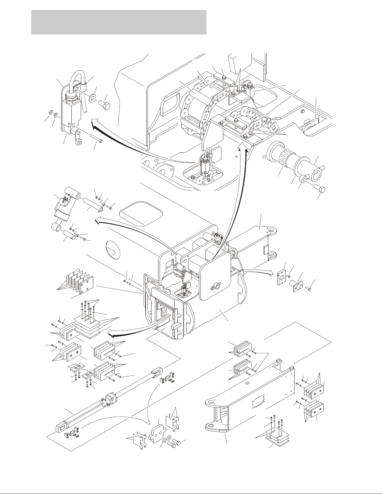
FIGURE 1-1. AXLE INSTALLATIONS
1-2 1100SB 3121266

SECTION 1 FRAME
FIGURE 1-1. AXLE INSTALLATIONS
ITEM # PART NUMBER QTY. DESCRIPTION REV.
Ref AXLE INSTALLATIONS - COMMON PARTS
0271521 Ref Oscillating Axle K
1 0100011 AR Compound, Locking
2 0100019 AR Compound, Locking
3 0100081 AR Adhesive #454
4 0363037 4 Bar, Stop
5Not Used
6 0641606 40 Bolt 3/8in-16NC x 3/4in
7 0641608 48 Bolt 3/8in-16NC x 1in
8 0641609 32 Bolt 3/8in-16NC x 1-1/8in
9 0641611 16 Bolt 3/8in-16NC x 1-3/8in
10 Not Used
11 0641613 8 Bolt 3/8in-16NC x 1-5/8in
12 Not Used
13 0641624 4 Bolt 3/8in-16NC x 3in
14 0641808 8 Bolt 1/2in-13NC x 1in
15 Not Used
16 0642214 1 Bolt 3/4in-10NC x 1-3/4in
17 0962033 2 Bushing
18 1180358 4 Carrier
7024365 AR 24 in Section Repair Kit (Includes Inner & Outer Links, Joining
Bars & Rollers, and Assembling Hardware)
7024366 1 Mounting Bracket Kit (Includes Mounting Brackets for Both
Ends, 1 Roller Assembly and Assembling Hardware)
19 1320263 4 Clamp, Cable
20 1320298 4 Clamp, Hose
21 1684102 4 Axle Extension Cylinder Assembly (See CYLINDER SECTION
for Breakdown)
22 3310805 8 Locknut #8-32NC
23 3340881 8 Pad, Wear
24 Use 1001161401 2 Pad, Axle (was p/n 3340907)
25 Use 1001161402 8 Pad, Wear (was p/n 3340946)
26 Use 1001161403 32 Pad, Wear (was p/n 3340932)
27 3340939 8 Pad, Rubber
28 3422918 1 Pin
29 3422960 4 Pin
30 3573294 4 Plate
31 3573335 8 Plate
32 3841287 1 Keeper, Pin
33 3900270 4 Bolt, Shoulder 1/2in -13NC x 1-1/2in
34 3930820 8 Capscrew #8-32NC x 1-1/4in
35 to 36 Not Used
37 4071035 2 Shim #18 Gauge
38 4071036 4 Shim #11 Gauge
39 4071054 8 Shim #18 Gauge
40 4071055 12 Shim #11 Gauge
41 4071039 24 Shim #18 Gauge
42 4071040 36 Shim #11 Gauge
3121266 1100SB 1-3

SECTION 1 FRAME
FIGURE 1-1. AXLE INSTALLATIONS (CONTINUED)
ITEM # PART NUMBER QTY. DESCRIPTION REV.
43 4071042 24 Shim #16 Gauge
44 to 45 Not Used
46 4360578 4 Switch, Limit (Note: P/N 4360578 does not include #57
Connector - Purchase Separately)
47 4711600 140 Flatwasher 3/8in Thin
48 4740461 1 Thrustwasher
49 4750800 8 Flatwasher #8 Regular
50 4846637 4 Extension, Axle
51 4846383 1 Box, Axle Pivot
52 0681813 12 Bolt 1/2in-13NC x 1-5/8in (Grade 8)
53 0681814 18 Bolt 1/2in-13NC x 1-3/4in (Grade 8)
54 0681815 12 Bolt 1/2in-13NC x 1-7/8in (Grade 8)
55 0681816 6 Bolt 1/2in-13NC x 2in (Grade 8)
56 4711800 48 Flatwasher 1/2in Thin
57 4460968 4 Connector, Strain Relief (Not Shown)
58 to 200 Not Used
Ref AXLE INSTALLATION - OPTIONAL PARTS
0271521 Ref Oscillating Axle K
201 to 211
212 0642020 4 Bolt 5/8in-11NC x 2-1/2in
213 to 216 Not Used
217 1684081 2 Oscillating Axle Cylinder Assembly (See CYLINDER SECTION
for Breakdown)
218 to 219 Not Used
220 3312005 4 Locknut 5/8in-11NC
221 to 224 Not Used
225 3422833 2 Pin
226 3422915 2 Pin
227 to 230 Not Used
231 3841258 4 Keeper, Pin
232 to 245 Not Used
246 4712000 4 Flatwasher 5/8in Thin
247 to 253 Not Used
254 3520054 4 Plug (Not Shown)
1-4 1100SB 3121266

SECTION 1 FRAME
FIGURE 1-1. AXLE INSTALLATIONS (CONTINUED)
ITEM # PART NUMBER QTY. DESCRIPTION REV.
3121266 1100SB 1-5
SECTION 1 FRAME
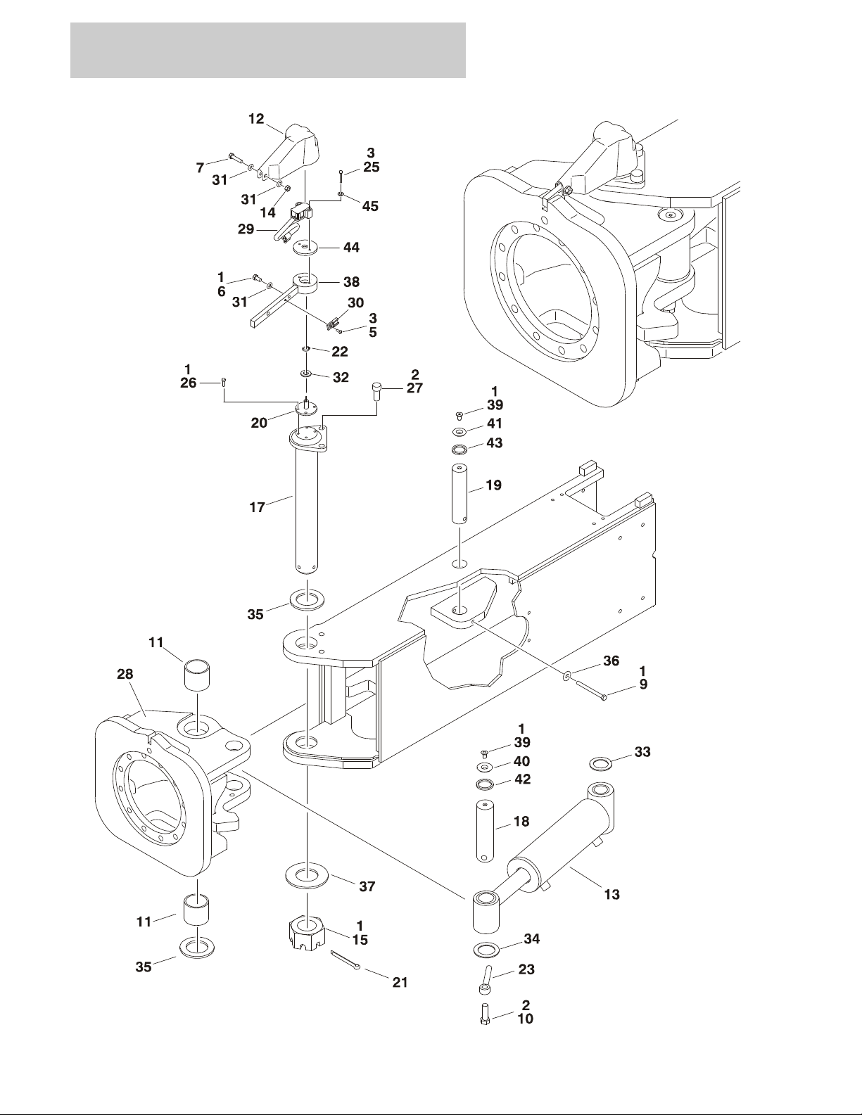
FIGURE 1-2. STEER INSTALLATION
1-6 1100SB 3121266

SECTION 1 FRAME
FIGURE 1-2. STEER INSTALLATION
ITEM # PART NUMBER QTY. DESCRIPTION REV.
0271520 Ref STEER INSTALLATION J
1 0100011 AR Compound, Locking
2 0100019 AR Compound, Locking
3 0100035 AR Compound, Locking
4Not Used
5 0630464 4 Screw, Button Head #10-24NC x 1/2in
6 0641505 4 Bolt 5/16in-18NC x 5/8in
7 0641511 4 Bolt 5/16in-18NC x 1-3/8in
8Not Used
9 0641634 4 Bolt 3/8in-16NC x 4-1/4in
10 0642016 4 Bolt 5/8in-11NC x 2in
11 0962423 8 Bushing
12 1671040 4 Cover, Sensor
13 1684314 4 Steer Cylinder Assembly (See CYLINDER SECTION for
Breakdown)
14 3311505 4 Locknut 5/16in-18NC
15 3300464 4 Nut, Slotted
16 Not Used
17 3422917 4 Kingpin
18 3422940 4 Pin, Steer Cylinder (Outer)
19 3422941 4 Pin, Steer Cylinder (Inner)
20 3423256 4 Pin, Sensor
21 3451214 4 Pin, Cotter 3/8in x 3-1/2in
22 3760383 4 Ring, Retaining
23 3841258 4 Keeper, Pin
24 Not Used
25 3931020 8 Capscrew #10-24NC x 1-1/4in
26 3931412 16 Capscrew 1/4in-20NC x 3/4in
27 3932024 8 Capscrew 5/8in-11NC x 1-1/2in
28 1001099632 4 Spindle
29 4360505 4 Switch, Rotary Angle Sensor (Steer)
30 4460914 4 Terminal
31 4711500 12 Flatwasher 5/16in Thin
32 4711800 4 Flatwasher 1/2in Thin
33 4740181 4 Thrustwasher
34 4740229 4 Thrustwasher
35 4740505 8 Thrustwasher
36 4751600 4 Flatwasher 3/8in Regular
37 4755000 4 Flatwasher 2-1/2in Regular
38 0200833 4 Arm, Steer
39 0741606 8 Screw, Countersunk 3/8in-16NC x 3/4in
40 1120549 4 Cap, Seal (Outer)
41 1120550 4 Cap, Seal (Inner)
42 3960551 4 Seal (Outer)
43 3960552 4 Seal (Inner)
44 0080277 4 Adapter, Angle Sensor Pilot
45 4750800 8 Flatwasher M8
3121266 1100SB 1-7
SECTION 1 FRAME
301
302
101
4
3
1
SPINDLE
REF.
20420
3
102
202 LH201 R
H
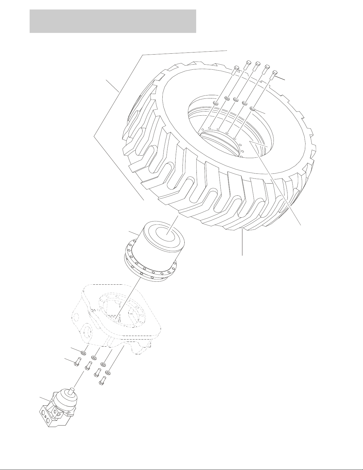
FIGURE 1-3. TIRE AND WHEEL DRIVE INSTALLATION
1-8 1100SB 3121266

SECTION 1 FRAME
FIGURE 1-3. TIRE AND WHEEL DRIVE INSTALLATION
ITEM # PART NUMBER QTY. DESCRIPTION REV.
Ref WHEEL DRIVE INSTALLATION
0275685 Ref Drive with Bonfiglioli Drive Hub B
1001104324 Ref Drive with Reggiana Riduttori Drive Hub A
1 0100019 AR Compound, Locking
2Not Used
3 0701617 48 Bolt M16 x 45mm (12 Per Wheel)
4 4892000 48 Washer Hardened 5/8in (12 Per Wheel)
Ref HUB AND MOTOR ASSEMBLY
2780286 Ref Drive with Bonfiglioli Drive Hub C
1001104315 Ref Drive with Reggiana Riduttori Drive Hub A
101 4 Drive Hub Assembly Options:
Ref Note: Various brands used on Machines Built SN 0300100131
to Present. When replacing complete hub, note that all 4 hubs
must be the same brand.
Ref Note: Various brands used on Machines Built SN 0300100131
to Present. Identify brand before ordering replacement parts.
1001093243 Bonfiglioli Hub (was p/n 2780290) (See DRIVE HUB
ASSEMBLY - BONFIGLIOLI for Breakdown)
1001104325 Reggiana Riduttori Hub (See DRIVE HUB ASSEMBLY -
REGGIANA RIDUTTORI for Breakdown)
102 3160339 4 Drive Motor Assembly (See DRIVE MOTOR ASSEMBLY for
Breakdown)
Ref TIRE AND WHEEL INSTALLATIONS
0271852 Ref Foam-Filled Tires B
Ref Note: Assemblies may require ballast/foam filling to
manufacturer’s specifications prior to installing on a
machine. Refer to Operation & Safety or Service &
Maintenance Manuals. Purchase individual tire and/or rim
only if able to foam fill tire & wheel assembly, otherwise,
purchase complete assembly.
201 0272055 2 Right Side Tire & Wheel Assembly (See Items 301-302 for
Breakdown)
202 0272056 2 Left Side Tire & Wheel Assembly (See Items 301-302 for
Breakdown)
203 0701619 64 Bolt M16 x 55mm (16 Per Wheel)
204 4892000 64 Washer Hardened 5/8in (16 Per Wheel)
Ref TIRE AND WHEEL ASSEMBLY COMPONENTS
301 4520261 4 Tire 445/50D710 (For Foam Filling)
302 4860236 4 Wheel Rim Only
3121266 1100SB 1-9
31
32
33
343536
102
373839404142434445464748101
108
105
106
104
103
23
22
21
20
19
18
17
16
141213
12
11
10
9
8
7
6
5
4
3
2
1
50
49
109
151
SECTION 1 FRAME
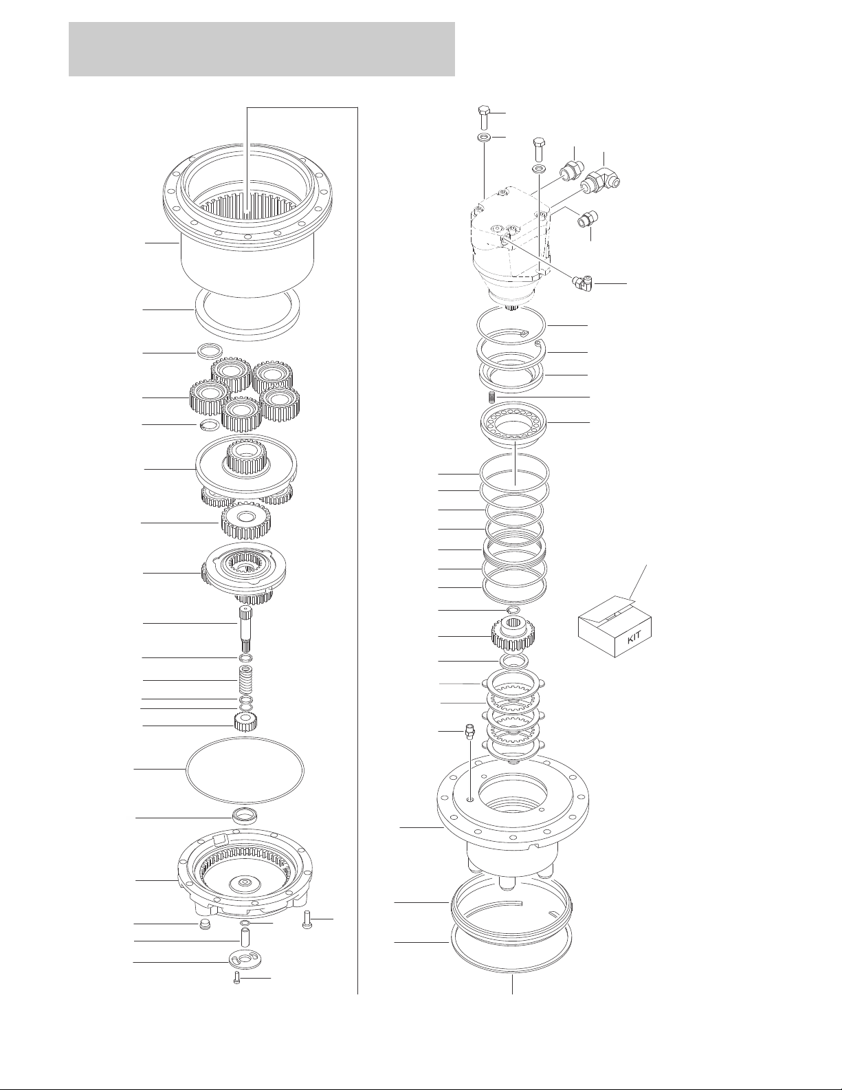
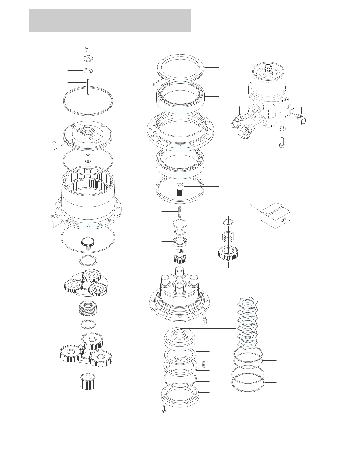
FIGURE 1-4. DRIVE HUB ASSEMBLY - BONFIGLIOLI
1-10 1100SB 3121266

SECTION 1 FRAME
FIGURE 1-4. DRIVE HUB ASSEMBLY - BONFIGLIOLI
ITEM # PART NUMBER QTY. DESCRIPTION REV.
1001093243 Ref DRIVE HUB ASSEMBLY WITH FITTINGS & HARDWARE C
Ref Note: Various brands used on Machines Built SN 0300100131
to Present. Identify brand before ordering replacement parts.
1001093242 1 Hub, Torque Less Fittings
1 70000810 10 Bolt M10 x 25
2 70000811 1 O-Ring
3 70000812 1 Pin
4 70000813 2 Bolt M8 x 16
5 70002393 1 Cap, Disconnect
6 See Note 2 Plug (Note: Not Available For Purchase)
7 70002394 1 Cover Assembly (Includes Items 2-6 & 8)
8 70000816 1 Pad
9 70000817 1 O-Ring
10 70000818 1 Gear, Primary Sun
11 Use 70000819 1 Ring, Neoprene
12 Use 70000819 2 Washer
13 Use 70000819 1 Spring
14 Use 70000819 1 Shaft
15 Not Used
16 70000820 1 Reduction Assembly, Primary
17 70000821 1 Gear, Secondary Sun
18 70000822 1 Reduction Assembly, Secondary
19 70000823 5 Snap Ring
20 70000824 5 Gear Assembly, Planetary
21 70000825 5 Spacer
22 70000826 1 Nut
23 70002395 1 Housing, Hub
24 to 30 Not Used
31 Use 1001093242 1 Spindle (Note: Not Available - Purchase Complete Drive Hub
Assembly)
32 70000834 4 Disc, Steel
33 70000835 5 Disc, Lined
34 70000836 1 Spacer
35 70002398 1 Shaft, Brake
36 70000838 1 Snap Ring
37 70000839 1 Ring, Backup
38 70000840 1 O-Ring
39 70000841 1 Spacer
40 70000842 1 Ring, Backup
41 70000843 1 O-Ring
42 70000844 1 O-Ring
43 70000845 1 Ring, Backup
44 70000846 1 Piston, Brake
45 70000847 15 Spring
46 70000848 1 Plate, Spring Retainer
47 70000849 1 Snap Ring
48 Use 3790158 O-Ring (was p/n 70002399)
49 70002396 1 Circlip
3121266 1100SB 1-11

SECTION 1 FRAME
FIGURE 1-4. DRIVE HUB ASSEMBLY - BONFIGLIOLI (CONTINUED)
ITEM # PART NUMBER QTY. DESCRIPTION REV.
50 70002397 1 Seal
51 to 100 Not Used
101 0761215 2 Bolt M12 x 35mm
102 2110404 1 Fitting, Adapter
103 2110808 1 Fitting, Adapter
104 2110812 1 Fitting, Adapter
105 2130406 1 Fitting, Elbow Adapter
106 2130812 1 Fitting, Elbow Adapter
107 Not Used
108 5241200 2 Washer, 12mm Hardened
109 0100011 AR Compound, Locking
110 to 150 Not Used
— — — — — — — — — —
151 70000819 1 Brake Shaft Kit (Includes Items 11-14)
1-12 1100SB 3121266

SECTION 1 FRAME
FIGURE 1-4. DRIVE HUB ASSEMBLY - BONFIGLIOLI (CONTINUED)
ITEM # PART NUMBER QTY. DESCRIPTION REV.
3121266 1100SB 1-13
SECTION 1 FRAME
MOTOR SHOWN HERE
FOR CLARITY
50
49
48
47
46
45
44
43
42
41
39
40
38
37
36
35
34
33
32
31
28
29
30
26
27
26
101
110
105
103
104
106
24
25
23
22
18
20
19
18
17
16
15
102
7
5
4
3
6
13
12
11
10
9
8
2
1
525351
109
FIGURE 1-5. DRIVE HUB ASSEMBLY - REGGIANA RIDUTTORI
1-14 1100SB 3121266

SECTION 1 FRAME
FIGURE 1-5. DRIVE HUB ASSEMBLY - REGGIANA RIDUTTORI
ITEM # PART NUMBER QTY. DESCRIPTION REV.
1001104325 Ref DRIVE HUB ASSEMBLY WITH FITTINGS & HARDWARE C
Ref Note: Various brands used on Machines Built SN 0300100131
to Present. Identify brand before ordering replacement parts.
1001101550 1 Hub, Torque Less Fittings
1 70002015 8 Bolt M8 x 25
2 70002016 1 Ring, Motor Support
3 Use 70002248 1 O-Ring
4 70002018 1 Snap Ring
5 70002019 1 Retainer, Spring
6 70002020 9 Spring
7 Use 70002249 1 Piston (was p/n 70002021)
8 See Note 1 Ring, Backup (Note: Use Item 51 or 53.)
9 See Note 1 O-Ring (Note: Use Item 51 or 53.)
10 See Note 1 O-Ring (Note: Use Item 51 or 53.)
11 See Note 1 Ring, Backup (Note: Use Item 51 or 53.)
12 70002026 5 Disc, Friction
13 70002027 6 Disc, Steel
14 Not Used
15 70002029 1 Spindle
16 70002030 4 Gear, Planetary
17 70002031 4 Bearing
18 70002032 5 Snap Ring
19 70002033 1 Gear, Brake/Input
20 70002034 1 Bearing
21 Not Used
22 70002035 1 Ring, Wear
23 70002036 1 Spring
24 70002037 1 Shaft, Engagement
25 Use 70002248 1 Seal
26 70002039 2 Bearing Assembly
27 70002040 1 Support, Hub
28 70002041 1 Nut, Retaining
29 Use 70002674 4 Washer (was p/n 70002042)
30 Use 70002674 4 Screw (was p/n 70002043)
31 70002044 1 Gear, Planetary Sun
32 70002045 1 Reduction Assembly, Secondary
33 70002046 1 Snap Ring
34 70002047 1 Gear, Secondary Input Sun
35 70002048 1 Reduction Assembly, Primary
36 70002049 1 Snap Ring
37 70002050 1 Gear, Primary Input Sun
38 Use 70002248 1 O-Ring
39 Use 1001101550 1 Housing, Hub (Note: Not Available - Purchase Complete
Drive Hub Assembly)
40 70002052 2 Screw, Countersunk
41 See Note 1 O-Ring (Note: Use Item 51 or 52.)
42 Use 70002247 1 Thrustwasher
43 See Note 1 O-Ring (Note: Use Item 51 or 52.)
3121266 1100SB 1-15

SECTION 1 FRAME
FIGURE 1-5. DRIVE HUB ASSEMBLY - REGGIANA RIDUTTORI (CONTINUED)
ITEM # PART NUMBER QTY. DESCRIPTION REV.
44 Use 70002247 1 Cover, Hub
45 70002057 3 Plug
46 Use 70002247 1 Snap Ring
47 Use 70002247 1 Pin, Engagement
48 See Note 1 Gasket (Note: Use Item 51 or 52.)
49 Use 70002247 1 Cover, Engagement
50 Use 70002247 2 Screw
51 70002248 1 Seal Kit (Includes Items 3, 8-11, 25, 38, 41, 43 & 48)
52 70002247 1 Cover Kit (Includes Items 41-50)
53 70002249 1 Brake Kit (Includes Items 4-13)
54 to 100 Not Used
101 0761214 2 Bolt M12 x 30mm
102 2110404 1 Fitting, Adapter
103 2110808 1 Fitting, Adapter
104 2110812 1 Fitting, Adapter
105 2130406 1 Fitting, Elbow Adapter
106 2130812 1 Fitting, Elbow Adapter
107 Not Used
108 5241200 2 Washer, 12mm Hardened
109 0100011 AR Compound, Locking
110 3790158 1 O-Ring
1-16 1100SB 3121266

SECTION 1 FRAME
FIGURE 1-5. DRIVE HUB ASSEMBLY - REGGIANA RIDUTTORI (CONTINUED)
ITEM # PART NUMBER QTY. DESCRIPTION REV.
3121266 1100SB 1-17
SECTION 1 FRAME
1
2
3
3
4
5
6
7
8
9
10
11
12
13
14
15
16
17
20
21
18
19
22
23
24
25
26
27
28
29
30
31
32
33
34
35
36
34
51
52
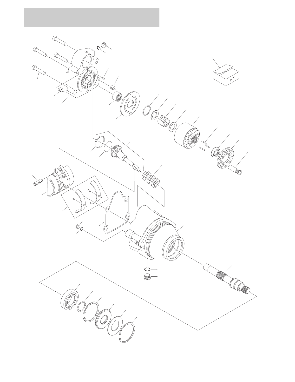
FIGURE 1-6. DRIVE MOTOR ASSEMBLY
1-18 1100SB 3121266

SECTION 1 FRAME
FIGURE 1-6. DRIVE MOTOR ASSEMBLY
ITEM # PART NUMBER QTY. DESCRIPTION REV.
3160339 Ref DRIVE MOTOR ASSEMBLY B
1 7022368 4 Bolt
2 70000859 1 End Cap, Motor
3 70003628 2 Locating Pin
4 Use 70000862 1 O-Ring
5 7007420 1 Plug (Includes Item 4)
6 7007446 1 Pin, Dowel
7 7021249 1 Bearing, Needle
8 70000854 1 Plate, Valve
9 7022311 1 Snap Ring
10 7022314 1 Retainer, Spring
11 7024867 1 Spring
12 7024868 1 Washer (was p/n 7022313)
13 70000855 1 Block, Cylinder
14 7021275 3 Pin, Slipper
15 70000856 1 Guide
16 70000857 1 Retainer, Slipper
17 7024865 9 Piston, Cylinder
18 Use 70000862 1 Ring, Piston
19 Use 70000862 1 O-Ring
20 70000860 1 Piston, Servo (Includes Items 18 & 19)
21 70000861 1 Spring
22 See Note 1 Pin (Note: Not Available For Purchase)
23 70000853 1 Swashplate
24 70000852 1 Bearing Kit
25 Use 70000862 1 Gasket
26 See Note 1 Plug (Note: Not Available For Purchase)
27 Use 70000862 1 O-Ring
28 7022321 1 Plug (Includes Item 29)
29 Use 70000862 1 O-Ring
30 Use 3160339 1 Housing (Note: Not Available - Purchase Complete Drive
Motor Assembly)
31 70000858 1 Shaft
32 7007437 1 Bearing
33 7007439 1 Snap Ring
34 7007438 2 Snap Ring
35 Use 70000862 1 Seal
36 7022371 1 Washer, Seal Support
37 to 50 Not Used
51 70000862 Motor Seal Kit (Includes Items 4,18,19,25,27,29 & 35)
52 7027740 Cylinder Block Kit (Includes Items 9 - 17)
3121266 1100SB 1-19
SECTION 1 FRAME
D
27
251
630
B
1
1
1
6
6
6
18
18
18
15
A
14
301
304
305
302
303
2
1
16
301
306
110
101
111
111
110
104
OR
A
B
C
C
D
E
E
1
103
1
0
3
106
106
109
102
105
105
102
102
102
108
108
102
223
5
17
9
8
1
02107
20
23
22
23
21
302
303
301
14
2
16
11
305
304
306
204
204
204
201
204
201
221
203
212
214
222
219
216
217
218
202
214
211
220
204
204
204
204
204
204
209
206
208
204
206
210
207
207
209
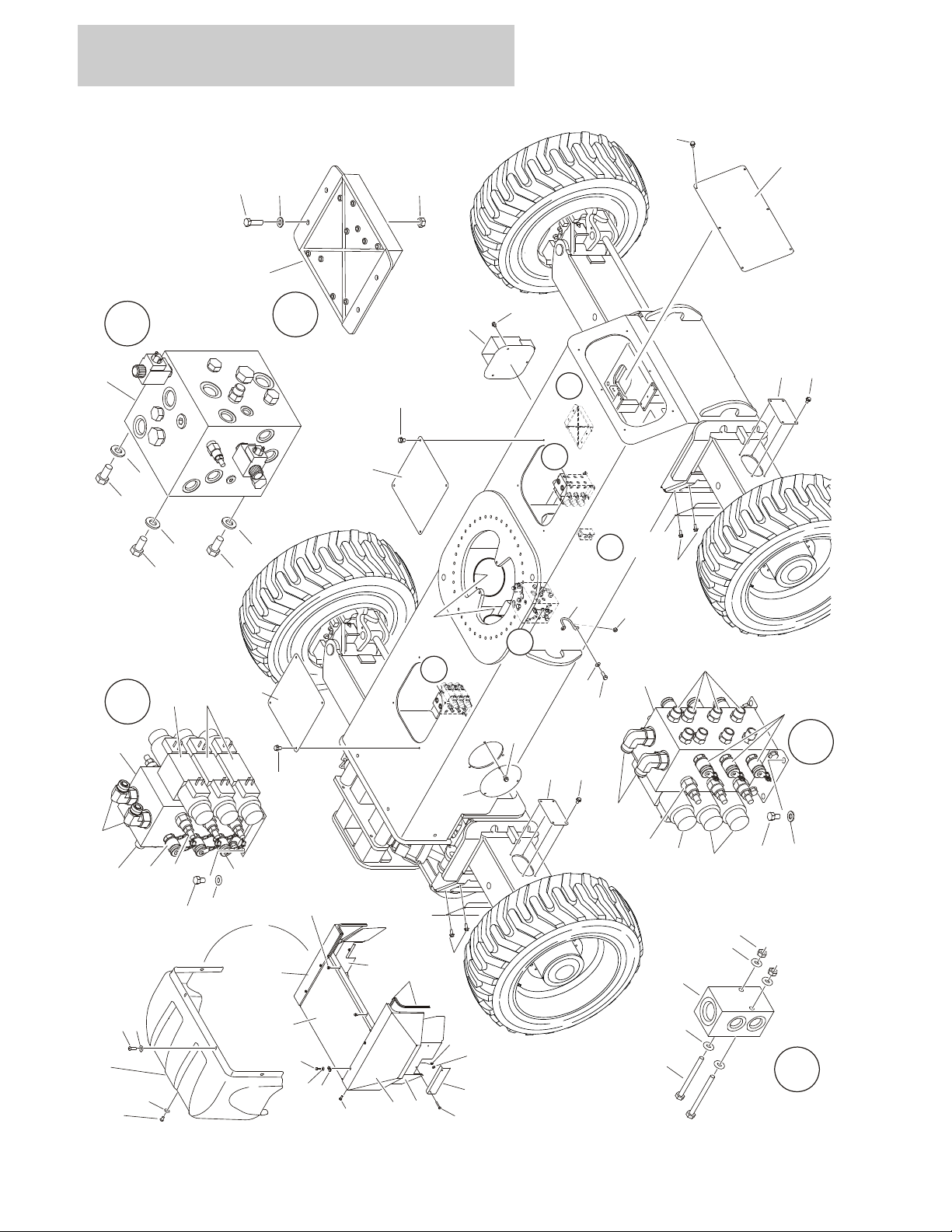
FIGURE 1-7. FRAME VALVES AND COVERS INSTALLATION
1-20 1100SB 3121266

SECTION 1 FRAME
FIGURE 1-7. FRAME VALVES AND COVERS INSTALLATION
ITEM # PART NUMBER QTY. DESCRIPTION REV.
0271802 Ref FRAME VALVES INSTALLATION K
1 0100011 AR Compound, Locking
2 0641504 8 Bolt 5/16in-18NC x 1/2in
3 to 4 Not Used
5 0641608 12 Bolt 3/8in-16NC x 1in
6 0641808 4 Bolt 1/2in-13NC x 1in
7Not Used
8 3311605 4 Locknut 3/8in16NC
9 3841340 2 Loop, Hose
10 Not Used
11 4060808
12 to 13 Not Used
14 4641268 2 Valve Assembly - Steer (See Items 301-306)
15 4641454 1 Valve Assembly - Traction (See TRACTION VALVE ASSEMBLY
16 4711500 23 Flatwasher 5/16in Thin
17 4711600 AR Flatwasher 3/8in Thin
18 4711800 4 Flatwasher 1/2in Thin
19 Not Used
20 0641424 2 Bolt 1/4in-20NC x 3in
21 3311405 AR Locknut 1/4in-20NC
22 4641155 1 Manifold, Junction
23 4711400 AR Flatwasher 1/4in Thin
24 Not Used
25 0641509 4 Bolt 5/16in-18NC x1-1/8in
26 Not Used
27 Use 1001112758 1 Module (Chassis) (Note: Control System must be recalibrated
2915024 1 Update Kit (Includes Cables, Programming Instructions & CD
28 to 29 Not Used
30 3311505 4 Locknut 5/16in-18NC
124in/3.2m
Flex-Trim
for Breakdown)
when Module is replaced) (was p/n 1600331 prior to
SN 0300141586)
Software)
0271523 Ref FRAME COVERS INSTALLATION (MACHINES WITH ABS
COVERS) (SN 0300073745 ONLY)
101 0100011 AR Compound, Locking
102 0791604 42 Screw 3/8in-16NC x 1/2in
103 0791607 16 Screw 3/8in-16NC x 7/8in
104 1670996 1 Cover, Front
105 1671045 4 Plate, Cover (Axle Side)
106 1671046 4 Plate, Cover (Axle Corner)
107 1671047 1 Plate, Cover (Rear)
108 1671048 2 Plate, Cover (Frame Top)
109 1671049 4 Plate, Cover (Frame Side)
110 3900283 7 Screw, Button Head 3/8in-16NC x 3/4in
111 4751600 7 Flatwasher 3/8in Regular
C
3121266 1100SB 1-21

SECTION 1 FRAME
FIGURE 1-7. FRAME VALVES AND COVERS INSTALLATION (CONTINUED)
ITEM # PART NUMBER QTY. DESCRIPTION REV.
1001110114 Ref FRAME COVERS INSTALLATION (MACHINES WITH STEEL
COVERS)
201 0100011 AR Compound, Locking
202 0641406 8 Screw 1/4in-20NC x 3/4in
203 0641414 4 Screw 1/4in-20NC x 1-3/4in
204 0791604 63 Screw 3/8in-16NC x 1/2in
205 Not Used
206 1671045 4 Plate, Cover (Axle Side)
207 1671046 4 Plate, Cover (Axle Corner)
208 1671047 1 Plate, Cover (Rear)
209 1671048 2 Plate, Cover (Frame Top)
210 1671049 3 Plate, Cover (Frame Side)
211 3300454 8 Nut, Retainer 1/4in-20NC
212 3311405 4 Locknut 1/4in-20NC
213 Not Used
214 4711400 12 Flatwasher 1/4in Thin
215 Not Used
216 1001110108 1 Cover - RH Side
217 1001110109 1 Cover - LH Side
218 1001110110 1 Cover - Center Side
219 1001110111 1 Shift - RH Side
220 1001110112 1 Shift - LH Side
221 1001110113 2 Plate
222 1001110513 51in/5.5m Seal
223 1001110877 1 Mount, Fire Extinguisher
C
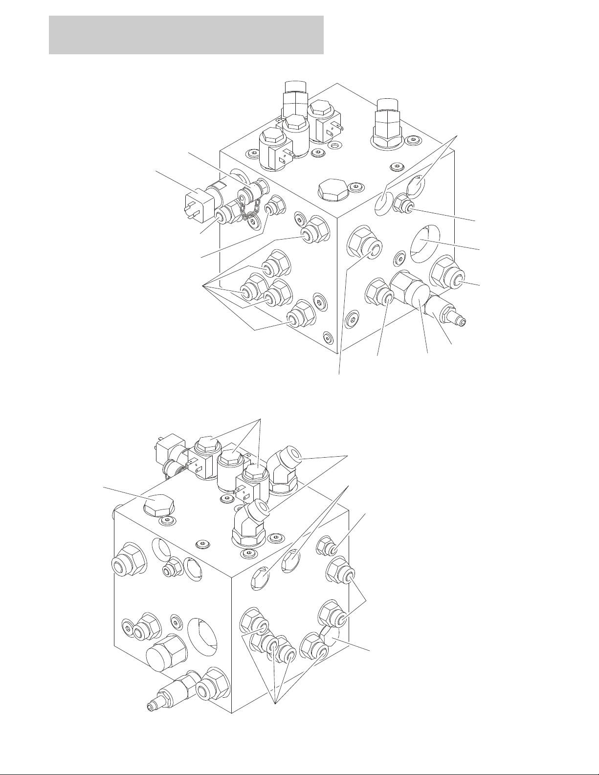
4641268 2 STEER VALVE ASSEMBLY
301 7026028 12 Cartridge (6 Per Valve)
7011346 12 Seal Kit - Cartridge (1 Per Cartridge)
302 7024927 4 Valve (2 Per Valve)
7012773 4 Seal Kit - Cartridge (1 Per Cartridge)
7018991 8 Coil (2 Per Valve)
303 Use 70001976 2 Valve (1 Per Valve) (was p/n 7012770)
7012773 2 Seal Kit - Cartridge (1 Per Cartridge)
7018991 4 Coil (2 Per Valve)
70001939 1 Orifice
304 2221086 6 Check, Pressure
305 2110606 8 Fitting, Straight
306 2130810 2 Fitting, Elbow
1-22 1100SB 3121266

SECTION 1 FRAME
FIGURE 1-7. FRAME VALVES AND COVERS INSTALLATION (CONTINUED)
ITEM # PART NUMBER QTY. DESCRIPTION REV.
3121266 1100SB 1-23
SECTION 1 FRAME
9
6
1
4
12
62883
10
10
10
10
10
11
11
11
7
7
5
FIGURE 1-8. TRACTION VALVE ASSEMBLY
1-24 1100SB 3121266

SECTION 1 FRAME
FIGURE 1-8. TRACTION VALVE ASSEMBLY
ITEM # PART NUMBER QTY. DESCRIPTION REV.
4641454 Ref TRACTION VALVE ASSEMBLY E
1 7012941 3 Cartridge, Solenoid Valve (Steer, Brake & Axle Lockout)
7010543 3 Seal Kit - 7012941 Cartridge
7012944 2 Coil
2 70000801 1 Cartridge, Valve (Relief)
7012998 1 Seal Kit - 70000801 Cartridge
3 70000802 1 Cartridge, Valve (Pilot)
7012942 1 Seal Kit - 70000802 Cartridge
4 70000803 1 Pressure Switch
5 70000804 1 Cartridge, Valve (Shuttle)
70000805 1 Seal Kit - 70000804 Cartridge
6 70000806 2 Cartridge, Valve (Flow Divider)
7017405 2 Seal Kit - 70000806 Cartridge
7 7012955 4 Cartridge, Valve (Check)
7012967 4 Seal Kit - 7012955 Cartridge
8 2111012 2 Fitting, Straight
9 2151012 2 Fitting, Elbow
10 2110810 13 Fitting, Straight
11 2110406 3 Fitting, Straight
12 2221086 1 Check, Pressure
13 2220883 1 Plug, #4 (Not Shown)
3121266 1100SB 1-25

SECTION 1 FRAME
FIGURE 1-8. TRACTION VALVE ASSEMBLY (CONTINUED)
ITEM # PART NUMBER QTY. DESCRIPTION REV.
1-26 1100SB 3121266

SECTION 2
TURNTABLE
3121266 1100SB 2-1

SECTION 2 TURNTABLE
13
7
17
5
3
16
112
112
112
105
115
113
115
101
101
101
101
108
102
118
106
109
115
115
115
117
107
107
116
116
114
114
103
119
111
24
23
28
29
1
1
1
5
17
26
110
201
202
203
206
115
101
204
205
104
FIGURE 2-1. VALVE, BATTERY, HORN & AUXILIARY PUMP INSTALLATIONS
2-2 1100SB 3121266

SECTION 2 TURNTABLE
FIGURE 2-1. VALVE, BATTERY, HORN & AUXILIARY PUMP INSTALLATIONS
ITEM # PART NUMBER QTY. DESCRIPTION REV.
0271802 Ref VALVES INSTALLATION - TURNTABLE MOUNTED K
1 0100011 AR Compound, Locking
2Not Used
3 0641506 4 Bolt 5/16in-18NC x 3/4in
4Not Used
5 0641608 12 Bolt 3/8in-16NC x 1in
6Not Used
7 0902755 1 Bracket, Valve Mounting
8 to12 Not Used
13 4641267 1 Main Valve Assembly (See MAIN VALVE ASSEMBLY for
Breakdown)
14 to 15 Not Used
16 4711500 23 Flatwasher 5 /16in Thin
17 4711600 14 Flatwasher 3/8in Thin
18 to 22 Not Used
23 4711400 8 Flatwasher 1/4in Thin
24 0641406 4 Bolt 1/4in-20NC x 3/4in
25 Not Used
26 0902800 1 Bracket, Module Mounting
27 Not Used
28 Use 1001112757 1 Module, B.L.A.M. (Note: Control System must be recalibrated
when Module is replaced) (was p/n 1600332 prior to
SN 0300141586)
2915024 1 Update Kit (Includes Cables, Programming Instructions & CD
Software)
29 3300454 4 Nut, Special
Ref BATTERY, HORN & AUXILIARY PUMP INSTALLATION
0271795 Ref With ABS Hoods (SN 0300073745 Only) E
1001110740 Ref With Steel Hoods A
101 0100011 AR Compound, Locking
102 0400020 1 Battery
103 0641408 1 Bolt 1/4in-20NC x 1in
104 0641606 2 Bolt 3/8in-16NC x 3/4in
105 0236768 4 Rod, Hold-down
106 0363062 2 Bar, Battery
107 3311405 3 Locknut 1/4in-20NC
108 3311601 4 Nut 3/8in-16NC
109 1 Tray Options:
3573259 Tray used with ABS Hoods (SN 0300073745 Only)
1001117359 Tray used with Steel Hoods (Not Shown)
110 3600424 1 Auxiliary Pump Assembly (See Items 201-206 for Breakdown)
111 3740067 1 Relay
112 3900283 7 Screw, Button Head
113 3980006 1 Seat, battery
114 4711400 4 Flatwasher 1/4in Thin
115 4711600 17 Flatwasher 3/8in Thin
116 4791400 2 Starwasher 1/4in
3121266 1100SB 2-3

SECTION 2 TURNTABLE
FIGURE 2-1. VALVE, BATTERY, HORN & AUXILIARY PUMP INSTALLATIONS (CONTINUED)
ITEM # PART NUMBER QTY. DESCRIPTION REV.
117 0140001 1 Horn
118 4420037
119 0641412 1 Bolt 1/4in-20NC x 1-1/2in
3600424 Ref AUXILIARY PUMP ASSEMBLY B
201 70001056 1 Motor Service Replacement Kit (Includes Motor, p/n 7011062
See Note 1 Brush Kit (Note: Not Available For Purchase)
202 7011062 1 Bracket, Motor/Pump (Part of Item 201)
7011016 1 Coupling (Part of Items 201 & 203)
7011044 1 Gasket (Part of Item 203)
203 7029593 1 Pump Service Replacement Kit (Includes Pump, p/n 7011016
See Note 1 Seal, Shaft (Note: Not Available For Purchase)
204 Use 7029593 1 Valve Components
205 Use 7029593 1 Valve Components
206 7011048 4 Screw
7011043 4 Flatwasher
17in/43cm
Tape, Insulation
Adapter, p/n 7011016 Coupling & qty 2 Setscrews)
Coupling, qty 2 Gaskets & qty 4 each of Screws & Washers)
2-4 1100SB 3121266

SECTION 2 TURNTABLE
FIGURE 2-1. VALVE, BATTERY, HORN & AUXILIARY PUMP INSTALLATIONS (CONTINUED)
ITEM # PART NUMBER QTY. DESCRIPTION REV.
3121266 1100SB 2-5

SECTION 2 TURNTABLE
1
4
102
106
16
108
103
111
104
105
113
1121314
115
109
107
101
114
103
103
19
3
114
7
7
114
114
114
7
7
7
2
114
121520
110
18
20
116
17
6
5
FIGURE 2-2. MAIN VALVE ASSEMBLY
2-6 1100SB 3121266

SECTION 2 TURNTABLE
FIGURE 2-2. MAIN VALVE ASSEMBLY
ITEM # PART NUMBER QTY. DESCRIPTION REV.
4641267 Ref MAIN VALVE ASSEMBLY B
1 7024573 1 Cartridge, Solenoid Valve (Dump)
7024574 1 Seal Kit - Cartridge
7011354 1 Coil
2 7021636 1 Cartridge, Solenoid Valve (Lift Flow)
7017495 1 Seal Kit - Cartridge
7017451 1 Coil
3 7021636 1 Cartridge, Solenoid Valve (Tele Flow)
7017495 1 Seal Kit - Cartridge
7017451 1 Coil
4 7024924 1 Control Valve Assembly (Swing)
7012773 1 Seal Kit - Valve
7018991 2 Coil
7021375 2 Nut, Coil
5 7024925 1 Control Valve Assembly (Lift)
7012773 1 Seal Kit - Valve
7018991 2 Coil
7021375 2 Nut, Coil
6Use 70001976 1 Control Valve Assembly (Tele) (was p/n 7012770)
7012773 1 Seal Kit - Valve
7018991 2 Coil
7021375 2 Nut, Coil
7 7026007 5 Cartridge, Relief Valve (Swing/Lift Up/Lift Down/Tele In/Tele Out)
7024574 1 Seal Kit - Cartridge
8 to 11 Not Used
12 7026000 1 Cartridge, Check Valve
7011311 1 Seal Kit - Cartridge
13 7026001 1 Cartridge, Check Valve
7011311 1 Seal Kit - Cartridge
14 7026002 1 Cartridge, Shuttle Valve
2900770 1 Seal Kit - Cartridge
15 7024570 1 Cartridge, Solenoid Valve (Aux Lift Down Select)
70001930 1 Seal Kit - Cartridge (was p/n 2900770)
7024571 1 Coil
16 7026003 1 Cartridge, Pilot Valve
7026004 1 Seal Kit - Cartridge
17 7026005 1 Cartridge, Solenoid Valve (Aux Lift Down)
7026006 1 Seal Kit - Cartridge
7024571 1 Coil
18 7026008 1 Cartridge, Check Valve
7011346 1 Seal Kit - Cartridge
19 7018942 12 Capscrew, Socket Head #10-24NC x 2in
20 7026016 1 Cartridge, Valve
7011346 1 Seal Kit - Cartridge
21 to 100 Not Used
101 2111216 1 Fitting, Straight
102 2130606 1 Fitting, Elbow
103 2110606 3 Fitting, Straight
3121266 1100SB 2-7

SECTION 2 TURNTABLE
FIGURE 2-2. MAIN VALVE ASSEMBLY (CONTINUED)
ITEM # PART NUMBER QTY. DESCRIPTION REV.
104 2110808 1 Fitting, Straight
105 2170316 1 Fitting, Tee
106 2131012 1 Fitting, Elbow
107 2110406 1 Fitting, Straight
108 2110408 1 Fitting, Straight
109 2110810 2 Fitting, Straight
110 2111010 2 Fitting, Straight
111 2110608 1 Fitting, Straight
112 2220890 1 Plug
113 Use 70002760 1 Plug (was p/n 2220888)
114 2221086 6 Check, Pressure
115 Use 70002758 2 Fitting, Plug (was p/n 2220883)
116 Use 70002759 1 Plug w/ O-Ring (was p/n 88662193 & 2220886)
2-8 1100SB 3121266

SECTION 2 TURNTABLE
FIGURE 2-2. MAIN VALVE ASSEMBLY (CONTINUED)
ITEM # PART NUMBER QTY. DESCRIPTION REV.
3121266 1100SB 2-9

SECTION 2 TURNTABLE
FIGURE 2-3. TURNTABLE SWING DRIVE AND BEARING INSTALLATION
2-10 1100SB 3121266

SECTION 2 TURNTABLE
FIGURE 2-3. TURNTABLE SWING DRIVE AND BEARING INSTALLATION
ITEM # PART NUMBER QTY. DESCRIPTION REV.
0271596 Ref SWING DRIVE INSTALLATION D
1 0100019 AR Compound, Locking
2 0682418 5 Bolt 7/8in- 9NC x 2-1/4in (Grade 8)
3 1 Swing Motor/Hub Assembly Options (See SWING MOTOR/HUB
ASSEMBLY for Breakdown)
Use 1001134098 Prior to SN 0300074374 (was p/n 3160281 & p/n 3160302)
Use 1001134098 SN 0300074374 to SN 0300152138 (was p/n 3160302)
Use 1001134098 SN 0300152138 to Present
4 3312002 1 Nut, Jam 5/8in-11NC
5 3900223 1 Screw, Shoulder
6 3952020 1 Setscrew 5/8in-11NC x 2-1/2in
7 4071041 1 Shim
8 4892400 5 Flatwasher 7/8in Hardened
0271512 Ref TURNTABLE BEARING AND LUBE INSTALLATION B
101 0100019 AR Compound, Locking
102 Use 2915072 1 Bearing Kit (was p/n 0440251) (Kit Includes Bearing & Mounting
Hardware)
103 0682026 40 Bolt 5/8in-11NC x 3-1/4in (Grade 8)
104 0682040 40 Bolt 5/8in-11NC x 5in (Grade 8)
105 2180002 2 Fitting, Grease
106 2180344 2 Fitting, Bulkhead
107 2220063 2 Fitting, Adapter
108 Not Used
109 2750528 2 Hose
110 4892000 80 Flatwasher 5/8in Hardened
0239842 Ref TURNTABLE LOCK INSTALLATION B
201 Not Used
202 3421565 1 Pin, Snap
203 1260017 9 in/23cm Chain - #3
204 3760170 2 Ring, Quick Release
205 3421563 1 Pin, Turntable Lock
Ref TURNTABLE WELDMENT OPTIONS:
4620149 Ref Machines with ABS Hoods (SN 0300073745 Only)
1001107391 Ref Machines with Steel Hoods
3121266 1100SB 2-11

SECTION 2 TURNTABLE
FIGURE 2-4. SWING MOTOR/HUB ASSEMBLY
2-12 1100SB 3121266

26
10
205
211
210
212
221
202
219
222
223
204
203
206
206
201
209
207
208
214
213
216
215
218
217
203
22
220
36
35
31
34
33
21
32
120
119
117
116
118
114
115
113
112
110
109
108
107
106
105
103
104
104
104
104
104
102
101
121
28
28
29
29
251
255
254
253
252
151
SECTION 2 TURNTABLE
3121266 1100SB 2-13

SECTION 2 TURNTABLE
FIGURE 2-4. SWING MOTOR/HUB ASSEMBLY
ITEM # PART NUMBER QTY. DESCRIPTION REV.
Ref SWING MOTOR/HUB ASSEMBLY OPTIONS:
3160281 Ref Prior to SN 0300074374
3160302 Ref SN 0300074374 to SN 0300151138
1001134098 Ref SN 0300151138 to Present
1 See Note 1 Housing/Shaft Assembly (Note: Not Available - Purchase
Complete Swing Motor/Hub Assembly)
1A 7024183 1 Shaft, Out put
1B 7000236 1 Seal, Lip
1C Use 1001091460 1 Cup, Bearing (was p/n 7000272 & p/n 90202500)
1D Use 1001091460 1 Cone, Bearing (was p/n 7000273 & p/n 90202501)
1E Use 1001091461 1 Cup, Bearing (was p/n 7000274
1F Use 1001091461 1 Cone, Bearing (was p/n 7000275 & p/n 90202503 )
1G 7024184 1 Housing
1H 7000239 1 Thrustwasher
1I 7000240 1 Ring, Retaining
1J 7017072 1 Plug, Pipe
2 7001917 1 Gear, Internal
3 7001918 1 Carrier Assembly
3A 7001900 1 Carrier
3B 7007645 6 Washer, Tanged
3C 7001902 84 Bearing, Needle
3D 7007646 3 Thrustwasher
3E 7001904 3 Shaft, Planet
3F 7001927 3 Gear, Cluster
3G 7001906 3 Rollpin
3H 7007648 6 Washer
4 7010467 1 Gear, Ring
5 7000224 2 O-Ring
6 7001920 1 Cover, Input
7 Not Used
8 7001922 1 Thrustwasher
9 Not Used
10 7024188 1 Motor Assembly (See Items 101-121 for Breakdown)
11 to 12 Not Used
13 7001921 1 Gear, Sun
14 Not Used
15 7000287 4 Thrustwasher
16 7000288 2 Bearing, Thrust
17 7001923 8 Bolt 3/8in-16NC x 3in (Grade 8)
18 7001924 4 Bolt, Shoulder 3/8in-16NC x 2-3/4in (Grade 8)
19 7001929 4 Lockwasher (Used with Item 18 Only)
20 7001928 1 Plug, Pipe
21 7001926 2 Plug, Pipe
22 7017082 1 Plug, Pipe
23 Not Used
24 See Note 1 Plate, ID (Note: Not Available for Purchase)
25 7000281 2 Screw, Drive
2-14 1100SB 3121266

SECTION 2 TURNTABLE
FIGURE 2-4. SWING MOTOR/HUB ASSEMBLY (CONTINUED)
ITEM # PART NUMBER QTY. DESCRIPTION REV.
26 1 Brake Assembly Options (See Items 201-223 for Breakdown):
7024182 Prior to SN 0300151138
70003524 SN 0300151138 to Present
27 7024763 1 O-Ring
28 See Note 2 Lug, Lifting (Note: Not Available for Purchase)
29 7024185 2 Bolt 1/2in-13NC x 5in (Grade 8)
30 Not Used
31 7000731 1 Gasket
32 AR Valve Options:
Used With Swing Motor/Hub Assembly p/n 3160281 & p/n
3160302
Use 4640741 1 Valve (was p/n 7024187)
7011320 2 Cartridge
2900770 2 Seal Kit - 7011320 Cartridge (1 Per Cartridge)
Used With Swing Motor/Hub Assembly p/n 1001134098
70003523 1 Valve
70003629 2 Cartridge
2900770 2 Seal Kit - 70003629 Cartridge (1 Per Cartridge)
33 See Note 4 Lockwasher (Note: Not Available for Purchase)
34 7024135 4 Bolt 5/16in-18NC x 2-1/2in (Grade 8)
35 7024186 1 Tube
36 7017085 2 Elbow
7024188 Ref MOTOR ASSEMBLY
101 7024391 5 Bolt
102 7004035 1 Cover, End
103 Use 7024389 1 Seal, Commutator
104 Use 7024389 5 Seal, Ring
105 Use 7024453 1 Commutator and Ring Assembly (was p/n 7004037)
106 Use 7004453 1 Ring
107 7024379 Manifold
108 7024392 1 Rotor Set
109 7024380 1 Plate, Wear
110 7024393 1 Link, Drive
111 Not Used
112 7024395 1 Shaft, Coupling
113 7024381 1 Bushing, Bronze
114 7004043 1 Thrustwasher
115 7004044 1 Bearing, Thrust
116 Use 7024389 Seal, Inner
117 Use 7024389 1 Washer, Back-up
118 7024394 1 Housing
119 7024390 1 Bearing
120 Use 7024389 1 Seal
121 7010795 1 Plug, O-Ring
122 to 150 Not Used
— — — — — — — — — —
151 Use 7024389 1 Seal Kit - 7024188 Motor (Includes Items 103, 104, 116,117 &
120) (was p/n 7024396)
3121266 1100SB 2-15

SECTION 2 TURNTABLE
FIGURE 2-4. SWING MOTOR/HUB ASSEMBLY (CONTINUED)
ITEM # PART NUMBER QTY. DESCRIPTION REV.
Ref BRAKE ASSEMBLIES
7024182 Ref Prior to SN 030015138
70003524 Ref SN 030015138 to Present
201 7024189 1 Shaft
202 Use 7024182 1 Housing (Note: Not Available For Purchase)
203 Use 7024193 2 Plate, Friction
204 Use 7024193 1 Plate, Pressure
205 7000731 1 Gasket
206 Use 7024193 2 Plate, Outer
207See Note 1Gasket (Note: Use Item 251, 254 or 255.)
208 7024191 1 Cylinder
209 7024192 1 Piston
210 Use 7024197 1 Bearing, Ball
211 Use 7024197 1 Ring, Retaining
212 Use 7024197 1 Seal, Shaft
213 See Note 6 Capscrew (Note: Not Available For Purchase)
214 See Note 6 Lockwasher (Note: Not Available For Purchase)
215 Use 7024194 1 O-Ring
216 Use 7024194 1 Ring, Back-up
217 Use 7024194 1 O-Ring
218 Use 7024194 1 Ring, Back-up
219 7024190 2 Pin, Dowel
220See Note 1Plug (Note: Not Available For Purchase)
221See Note 1Plug (Note: Not Available For Purchase)
222 Use 7024196 AR Spring (Natural)
223 Use 7024196 AR Spring, (Blue)
224 to 250 Not Used
— — — — — — — — — —
251 7024194 1 Seal Kit - Brake (Includes Items 205, 207 & 215-218)
252 Use 7024196 1 Spring Kit - Brake (Includes 12 Natural Colored Springs) (was p/
n 7024195)
Note: Spring Kit p/n 7024195 no Longer Available, Pur-
chase p/n 7024196 for Replacement.
253 7024196 1 Spring Kit - Brake (Includes 12 Natural & 2 Blue Colored
Springs)
254 7024193 1 Friction Disc Kit - Brake (Includes Items 203, 204, 206 & 207)
255 7024197 1 Bearing Kit - Brake (Includes Items 207 & 210-212)
2-16 1100SB 3121266

SECTION 2 TURNTABLE
FIGURE 2-4. SWING MOTOR/HUB ASSEMBLY (CONTINUED)
ITEM # PART NUMBER QTY. DESCRIPTION REV.
3121266 1100SB 2-17

1
1
18
48
19
4
15
16
25
14E
TO GROUND
14D
1
5
TO STARTER
2
7
11
20
382728
34
372728
34
TANK
REF.BATTE
R
Y
REF
.14
A14C14
B14A176ITEM (14
)
INCLUDE
S14
A THR
U 14E26
2
7
2
7
342827
34282
7393428
332834
2927342830
31
3
5
36
1
22
23
24
41
40
124
134
124
316
304
306
307
303
301
317
305
311
314
315
302
435
SECTION 2 TURNTABLE
FIGURE 2-5. DEUTZ TD2011 TIER III ENGINE INSTALLATION
2-18 1100SB 3121266

SECTION 2 TURNTABLE
1
5
0
1
751
0
3
168
1
2
0
146
1
6
8109129
1
5
4
1281551
0
2
1
82133103177
1
6
6
1
3
630916810310316
1
1
3
2
1
6
7
1
0
7
1
6
01951
3
1
1
1
6
R
E
X
R
O
T
H
P
U
M
P
C
O
M
P
O
N
E
N
T
S
S
A
U
E
R
P
U
M
P
C
O
M
P
O
N
E
N
T
S
1
6
9
1
3
9
A
1
7
8
1
3
9
1
7
4
1
0
3
1
1
2
1
5
6
1
1
8
130
15914
31711461461
6
8
168
1
101
091
831
0
310
6
1
8
0
1
0
3
1
1
7
1
52173
1
0
9
1
4
6
1
6
8
1
2
3
1
1
1
1
4
7
1
6
9
1
0
6
1
7
1
1
4
4
1
9
4
1
3
8
1
2
4
1
2
6
1
0
9
1
0
3
1
1
7
1
2
2
1
6
2
1
6
2
1
5
3
1
4
9
1
1
3
1
6
9
1
4
1
1
0
9
1
6
8
1
4
6
1
7
0
1
4
7
1
1
4
1
6
9
1
4
0
1
0
9
1
6
8
1
4
6
1
7
0
1
4
7
1
5
7
1
0
5
1
6
5
1
1
5
1
6
7
1
4
2
1
0
9
1
6
8
1
4
6
32614
6
2
1
1
5
1
1
1
7
1
8
9
1
5
8
1
7
1
1
0
6
1
8
4
1
4
4
1
7
2
1
9
0
1
0
8
1
0
4
1
2
7
1
6
7
1
4
5
1
9
3
1
2
5
1
2
5
1
2
3
1
1
1
1
4
7
1
6
9
1
8
1
O
R
174
174
174
103
112
103
112
188
198
199
196
197
1
3
9
B
2
0
1
2
0
2
4
3
5
1
3
9
C
1
3
9
D
3121266 1100SB 2-19

SECTION 2 TURNTABLE
FIGURE 2-5. DEUTZ TD2011 TIER III ENGINE INSTALLATION
ITEM # PART NUMBER QTY. DESCRIPTION REV.
Ref DEUTZ TD2011 DIESEL ENGINE INSTALLATION OPTIONS:
Ref Tier III Machines with Rexroth Pumps & ABS Hoods (SN
0300073745 Only)
1001098516 Ref With Skypower & Without Cold Weather Plus Package D
1001098517 Ref With Cold Weather Plus Package D
Ref Tier III Machines with Rexroth Pumps & Steel Hoods
1001117371 Ref With Skypower & Without Cold Weather Plus Package B
1001116015 Ref With Cold Weather Plus Package B
Ref Tier III Machines with Sauer Pumps & Steel Hoods
1001119053 Ref With Skypower & Without Cold Weather Plus Package B
1001119054 Ref With Cold Weather Plus Package B
1 0100011 AR Compound, Locking
2 0100079 AR Sealant, Pipe
3 1702942 1 Decal, Block Heater (Cold Weather Plus Package - Not
Shown)
4 0641610 1 Bolt 3/8in-16NC x 1-1/4in
5 0641808 1 Bolt 1/2in-13NC x 1in
6 0642010 1 Bolt 5/8in-11NC x 1-1/4in
7 1320022 3 Clamp
8 to 10 Not Used
11 2220313 1 Fitting, Elbow Barbed
12 to 13 Not Used
14 2902099 1 Battery Cable Kit C
14A 7024580 1 Cable, Red (To Aux Pump Relay, Battery Positive Terminal
& Start Relay)
14B 7024581 1 Cable, Black (To Aux Pump, Battery Negative Terminal &
Ground at Tray Pivot)
14C 7024582 1 Cable, Red (Aux Pump Relay to Aux Pump)
14D 7024583 1 Cable, Black (Tray Pivot to Engine Mount)
14E 7024584 1 Cable, Red (Start Relay to Starter)
15 3422446 1 Pin
16 3841143 1 Keeper, Pin
17 4752000 1 Flatwasher 5/8in Regular
18 AR Bolt Options:
0641406 2 Bolt 1/4in-20NC x 3/4in (Prior to SN 0300145302)
0641606 4 Bolt 3/8in-16NC x 3/4in (SN 0300145302 to Present)
19 1001108617 Pressure Filter
70002231 1 Element, Filter
20 2750532 55in/1.4m Hose
21 4711400 4 Flatwasher 1/4in Thin
22 0641511 1 Bolt 5/16in-18NC x 1-3/8in
23 1320187 1 Clamp, Twin
24 1320190 1 Cover, Clamp
25 2820170 1 Insulation, Sound Absorbing
26 4240099 AR Strap, Tie
27 0641509 18 Bolt 5/16in-18NC x 1-1/8in
28 3311505 23 Locknut 5/16in-18NC
2-20 1100SB 3121266

SECTION 2 TURNTABLE
FIGURE 2-5. DEUTZ TD2011 TIER III ENGINE INSTALLATION (CONTINUED)
ITEM # PART NUMBER QTY. DESCRIPTION REV.
29 1 Panel, Rubber Options:
3380472 Machines with ABS Hoods (SN 0300073745 Only)
1001111132 Machines with Steel Hoods
30 3573644 1 Plate, Tray Clamp
31 1 Plate, Top Clamp Options:
3573645 Machines with ABS Hoods (SN 0300073745 Only)
1001112878 Machines with Steel Hoods
32 1 Plate, Bottom Clamp Options:
3573646 Machines with ABS Hoods (SN 0300073745 Only)
1001112879 Machines with Steel Hoods
33 3900272 4 Screw, Button 5/16in-18NC x 1-3/4in
34 4711500 AR Flatwasher 5/16in Thin
35 3380473 1 Panel, Rubber
36 3573669 1 Plate, Clamp
37 1 Plate, Tray Clamp Options:
3573727 Machines with ABS Hoods (SN 0300073745 Only)
1001112880 Machines with Steel Hoods
38 3573728 1 Plate, Tray Clamp
39 0641506 1 Bolt 5/16in-18NC x 3/4in
40 2180348 1 Fitting, Barbed
41 2221176 1 Fitting, Elbow
42 0641605 3 Bolt 3/8in-16NC x 5/8in (Not Shown)
43 1671121 1 Cover, Generator (with Skypower) (Not Shown)
44 4711600 3 Flatwasher 3/8in Thin (Not Shown)
45 4240018 2 Strap, Tie (Not Shown)
46 0641410 4 Bolt 1/4in-20NC x 1-1/4in
47 2200222 1 Plug, Pipe (Used in Bottom of Fuel Tank - Not Shown)
48 AR Flatwasher Options:
4711400 2 Flatwasher 1/4in Thin (Prior to SN 0300145302)
4711600 4 Flatwasher 3/8in Thin (SN 0300145302 to Present)
Ref DEUTZ TD2011 DIESEL ENGINE ASSEMBLY
Ref Tier III Machines with Rexroth Pumps
1001098530 Ref With Skypower & Without Cold Weather Plus Package E
1001098531 Ref With Cold Weather Plus Package D
Ref Tier III Machines with Sauer Pumps
1001107973 Ref With Skypower & Without Cold Weather Plus Package D
1001107975 Ref With Cold Weather Plus Package D
101 Not Used
102 0080244 1 Spacer, Fan
103 0100011 AR Compound, Locking
104 0340003 2 Band, Air Cleaner
105 0340051 2 Band, Muffler
106 0641406 AR Bolt 1/4in-20NC x 3/4in
107 0641506 5 Bolt 5/16in-18NC x 3/4in
108 0641507 4 Bolt 5/16in-18NC x 7/8in
109 0641608 AR Bolt 3/8in-16NC x 1in
110 0641609 2 Bolt 3/8in-16NC x 1-1/8in
3121266 1100SB 2-21

SECTION 2 TURNTABLE
FIGURE 2-5. DEUTZ TD2011 TIER III ENGINE INSTALLATION (CONTINUED)
ITEM # PART NUMBER QTY. DESCRIPTION REV.
111 0641808 1 Bolt 1/2in-13NC x 1in
112 2 Bolt Options:
0641812 Bolt 1/2in-13NC x 1-1/2in
0641814 Bolt 1/2in-13NC x 1-3/4in
0761215 Bolt M12 x 35mm
113 0641818 2 Bolt 1/2in-13NC x 2-1/4in
114 0641826 2 Bolt 1/2in-13NC x 3-1/4in
115 0700810 3 Bolt M8 x 20mm
116 0711214 2 Bolt M12 x 30mm
117 AR Bolt Options:
0711414 M14 x 30mm
0711417 M14 x 45mm
118 1001112766 1 Bracket, Muffler
119 Not Used
120 0940070 1 Bumper
121 Not Used
122 0961986 2 Bushing, Flanged
123 1 Lanyard Options:
1060637 16in/40.6cm Length
1001131542 13in/33cm Length
124 1320022 AR Clamp
125 1320058 AR Clamp
126 1320223 1 J-Clip
127 1340065 1 Air Cleaner Assembly
7003655 1 Element, Air Cleaner
128 1671023 1 Shroud, Fan
129 0272060 1 Box, Air Intake
130 1703162 2 Decal - Fan Blade
131 1001098601 1 Engine, Deutz BF4M2011 Options: (See Items 301 to 327 for
Individually Serviced Components)
132 2060025 1 Fan
133 2220451 1 Fitting, Straight
134 2720058
135 Not Used
136 2720500 1 Hose, Oil Cooler (Top)
137 Not Used
138 2750532 9in/23cm Hose
139 2902065 1 Pump Coupling Kit G
139A Use 2902065 1 Plate, Pump Mounting (Note: Not Available for
139B 70000793 1 Coupling, Flex
139C Use 2902065 18 Capscrew M10 (Note: Not Available for Purchase.)
139D Use 2902065 12 Flatwasher M10 (Note: Not Available for Purchase.)
140 3200362 2 Mount, Motor (Front)
141 3200401 2 Mount, Motor (Rear)
142 3220126 1 Muffler
70003555 1 Clamp
143 3300454 10 Nut
144 3311405 AR Locknut 1/4in-20NC
145 3311505 5 Locknut 5/16in-18NC
34ft/10.3m
Hose
Purchase.)
2-22 1100SB 3121266

SECTION 2 TURNTABLE
FIGURE 2-5. DEUTZ TD2011 TIER III ENGINE INSTALLATION (CONTINUED)
ITEM # PART NUMBER QTY. DESCRIPTION REV.
146 3311605 AR Locknut 3/8in-16NC
147 3311805 5 Locknut 1/2in-13NC
148 Not Used
149 3422532 1 Pin, Hitch
150 3537416 1 Plate, Mounting (Front RIght)
151 3573529 1 Plate, Mounting (Front Left)
152 3539971 1 Bracket, Engine Mounting (Front)
153 3573142 1 Bracket, Engine Mounting (Rear)
154 4846552 1 Plate, Oil Cooler Mounting
155 1 Pulley Options:
3580320 With Skypower & Without Cold Weather Plus Package
3580320 With Cold Weather Plus Package
156 3600339 1 Pump Assembly - Rexroth (See PUMP ASSEMBLY -
REXROTH for Breakdown)
157 Use 1001145382 1 Cooler, Engine Oil (was p/n 3620041)
158 3740067 AR Relay, Start
159 3960543 1 Seal
160 3960544 1 Seal
161 4032022 4 Capscrew M10 x 90mm
162 4060805 8in/20cm Flex-Trim
163 to 164 Not Used
165 4568293 1 Pipe, Exhaust
166 4640751 1 Valve, Oil Drain
167 4711500 AR Flatwasher 5/16in Thin
168 4711600 AR Flatwasher 3/8in Thin
169 4711800 7 Flatwasher 1/2in Thin
170 4740274 4 Washer, Snubbing
171 4751400 AR Flatwasher 1/4in Regular
172 4791400 AR Starwasher 1/4in
173 4846946 1 Tray
174 AR Flatwasher, Hardened Options:
4891800 1/2in
4891600 3/8in
175 0641605 4 Bolt 3/8in16NC x 5/8in
176 0641610 4 Bolt 3/8in-16NC x 1-1/4in
177 2720501 1 Hose, Oil Cooler (Bottom)
178 3520054 2 Plug
179 3573411 2 Plate, Clamp
180 3573412 1 Gusset
181 1320060 1 Clamp
182 2220498 1 Fitting, Elbow
183 4740518 10 Washer, Nylon
184 AR Cable, Jumper Options:
4923592 1 All except Cold Weather Plus Package
1060904 1 With Cold Weather Plus Package
185 4240099 AR Tie, Wire (Not Shown)
186 4923468 AR Harness, Glow Plugs Options (Not Shown):
187 Not Used
188 3790152 1 O-Ring
189 4846945 1 Mount, Generator
3121266 1100SB 2-23

SECTION 2 TURNTABLE
FIGURE 2-5. DEUTZ TD2011 TIER III ENGINE INSTALLATION (CONTINUED)
ITEM # PART NUMBER QTY. DESCRIPTION REV.
190 3740080 2 Relay
191 2580062 1 Heater, Block (With Cold Weather Plus Package - Not Shown)
192 4460234 3 Mount, Wire Tie (Used to Secure Block Heater Cord) (With
Cold Weather Plus Package - Not Shown)
193 1001092856 1 Hose, Air Intake
194 8410013 1 Clamp, Gear
195 4060804 1ft/25cm Flex-Trim
196 1001108616 1 Pump Assembly - Sauer Tandem (See PUMP ASSEMBLY -
SAUER TANDEM for Breakdown)
197 1001108888 1 Pump Assembly - Sauer Piston (See PUMP ASSEMBLY -
SAUER PISTON for Breakdown)
198 1001112927 1 Pump Assembly - Sauer Gear (See PUMP ASSEMBLY -
SAUER GEAR for Breakdown)
199 3790155 1 O-Ring
1001098601 Ref DEUTZ TD2011 ENGINE COMPONENTS C
301 7027235 1 Dipstick
302 7020465 1 Cap, Filler
303 70001850 1 Pump, Oil
7020468 1 Seal Between Oil Pump & Engine Block (Not Shown)
304 7016331 1 Filter, Oil
305 4 Injector Pump Options:
Ref Note: Series Letter is shown on label at base of Injector
Pump.
70001128 AR “A” Series
70001129 AR “B” Series
70001130 AR “C” Series
70001131 AR “D” Series
306 7016328 1 Filter, Fuel
307 70000916 1 Pump Fuel Supply
70001435 1 Repair Kit
70000917 1 O-Seal Between Fuel Pump & Engine Block (Not Shown)
308 Not Used
309 7020414 1 V-Belt
310 7020471 4 Gasket, Exhaust Manifold to Cylinder Head (Not Shown)
7020486 1 Gasket, Exhaust Manifold to Exhaust Pipe (Not Shown)
311 70001867 1 Alternator
70001868 Regulator, Voltage (Not Shown)
312 7020479 1 Starter (Not Shown)
7026608 1 Solenoid
313 Not Used
314 7027791 1 Sender, Coolant Temperature
315 7027790 1 Sensor, Oil Pressure
316 7024565 1 Sensor, Speed
317 7027792 1 Actuator, Throttle
7027276 2 Spring
318 7020459 1 Thermostat (Not Shown)
319 to 320 Not Used
321 7024579 1 Gear, Ring
2-24 1100SB 3121266

SECTION 2 TURNTABLE
FIGURE 2-5. DEUTZ TD2011 TIER III ENGINE INSTALLATION (CONTINUED)
ITEM # PART NUMBER QTY. DESCRIPTION REV.
322 7027236 1 Sensor, Temperature (Not Shown)
323 7027239 1 Solenoid, Start (Not Shown)
324 7027240 1 Turbocharger (Not Shown)
325 Not Used
326 1600443 1 Module, EMR2 Controller
7027796 1 Harness, Controller (Not Shown)
327 70002718 1 Seal, Rear Main (Not Shown)
1283409 Ref DECALS INSTALLATION
401 to 434 Not Used
435 1001143852 1 Decal - EPA
3121266 1100SB 2-25

SECTION 2 TURNTABLE
22
BATTE
R
Y
REF
.
38
42
27
24
2
21
TANK
REF
.23C23B23
A23A4010I
TEM (23
)
INCLUDES23A THR
U 23E36
38246
383424
28
30
123
382
4 5
2
12
17
123
133
12
2
20
2
12
19
1
39
43
16
1
8
23
33
2
5
6
13
14
383224
6
383124
6
216
204
206
207
203
201
217
202
205
211
214
215
382
4
4
23E
23D
9
FIGURE 2-6. DEUTZ TD2011 TIER IVI-FLEX ENGINE INSTALLATION
2-26 1100SB 3121266

SECTION 2 TURNTABLE
1
1
3
7
B
1
1
9
1
5
5
1
3
4
2
0
9
1
3
2
1
3
5
1
3
1
2
1
8
1
0
2
1
1
8
1
8
2
1
3
6
1
2
1
1
6
4
1
6
7
1
2
6
1
1
0
1
0
2
1
0
2
1
1
8
1
0
6
1
7
3
1
7
9
1
0
7
1
2
5
1
4
4
1
6
8
2
2
8
2
3
0
1
2
8
1
3
7
A
1
1
6
1
7
0
1
3
9
1
7
1
1
4
6
1
7
0
1
1
5
1
4
0
1
7
1
1
4
6
189
190
1
5
6
1
4
9
1
0
212
0
R
E
X
R
O
T
H
P
U
M
P
C
O
M
P
O
N
E
N
T
S
S
A
U
E
R
P
U
M
P
C
O
M
P
O
N
E
N
T
S
1
0
2
1
1
8
1
1
0
1
6
9
1
4
5
1
1
0
1
6
9
1
4
5
1
5
0
1
0
9
1
0
2
1
6
9
1
5
3
1
4
2
1
7
314
5
1
6
91121
10169
14517
2
1
0
2
1
0
6
1
45169110175
1
0
2
1
6
2
1
3
0
1
6
8
1
0
2
1
0
7
1
0
3
1
6
9
1
601
61157
1
4
4
1
0
4
1
0
8
127
1
6
8
1
1
0
1
4
1
1
4
5
1
6
9
1
6
6
1
0
2
1
1
7
1
7
0
1
1
3
1
2
2
1
4
6
1
7
0
1
3
7
1
7
7
1
0
2
1
1
4
1
4
8
1
6
4
133
7
2
2
6
1
8
3
1
5
4
1
4
3
1
7
4
176
1
5
8
1
5
9
163
1
2
4
1
2
4
1
8
0
O
R
177
177
177
102
114
102
114
188
186
187
1
5
1
1
1
0
1
4
5
1
6
9
1
0
6
1
4
3
1
7
3
1
4
7
1
0
5
1
8
1
1
29152
1
3
7
C
137D
3121266 1100SB 2-27

SECTION 2 TURNTABLE
FIGURE 2-6. DEUTZ TD2011 TIER IVI-FLEX ENGINE INSTALLATION
ITEM # PART NUMBER QTY. DESCRIPTION REV.
Ref DEUTZ TD2011 DIESEL ENGINE INSTALLATION OPTIONS:
Ref Tier IVi-Flex Engines (SN 0300171079 to Present with Rexroth
Pumps & Steel Hoods)
1001137791 Ref With Skypower & Without Cold Weather Plus Package A
1001137793 Ref With Cold Weather Plus Package A
Ref Tier IVi-Flex Engines (SN 0300171079 to Present with Sauer
Pumps & Steel Hoods)
1001137799 Ref With Skypower & Without Cold Weather Plus Package A
1001137801 Ref With Cold Weather Plus Package A
1 0100011 AR Compound, Locking
2 0100079 AR Sealant, Pipe
3 0641610 4 Bolt 3/8in-16NC x 1-1/4in
4 0641506 1 Bolt 5/16in-18NC x 3/4in
5 0641509 7 Bolt 5/16in-18NC x 1-1/8in
6 0641511 13 Bolt 5/16in-18NC x 1-3/8in
7 0641605 3 Bolt 3/8in-16NC x 5/8in
8 0641410 1 Bolt 1/4in-20NC x 1-1/4in
9 0641808 1 Bolt 1/2in-13NC x 1in
10 0642010 1 Bolt 5/8in-11NC x 1-1/4in
11 Not Used
12 1320022 3 Clamp
13 1320187 1 Clamp, Twin
14 1320190 1 Cover, Clamp
15 1671121 1 Cover, Generator (with Skypower) (Not Shown)
16 1001108617 1 Filter
70002231 1 Element, Filter
17 2180348 1 Fitting, Barbed
18 2200222 1 Plug, Pipe (Used in Bottom of Fuel Tank) (Not Shown)
19 2220313 1 Fitting, Elbow Barbed
20 2221176 1 Fitting, Elbow
21 2750532 55in/1.4m Hose
22 2820170 1 Insulation, Sound Absorbing
23 2902099 1 Battery Cable Kit
23A 7024580 1 Cable, Red (To Aux Pump Relay, Battery Positive Terminal
& Start Relay)
23B 7024581 1 Cable, Black (To Aux Pump, Battery Negative Terminal &
Ground at Tray Pivot)
23C 7024582 1 Cable, Red (Aux Pump Relay to Aux Pump)
23D 7024583 1 Cable, Black (Tray Pivot to Engine Mount)
23E 7024584 1 Cable, Red (Start Relay to Starter)
24 3311505 24 Locknut 5/16in-18NC
25 3380473 1 Panel, Rubber
26 3422446 1 Pin
27 3573644 1 Plate, Tray Clamp
28 1001112878 1 Plate, Top Clamp
29 1001112879 1 Plate, Bottom Clamp
30 3573669 1 Plate, Clamp
31 1001112880 1 Plate, Tray Clamp
32 3573728 1 Plate, Tray Clamp
2-28 1100SB 3121266

SECTION 2 TURNTABLE
FIGURE 2-6. DEUTZ TD2011 TIER IVI-FLEX ENGINE INSTALLATION (CONTINUED)
ITEM # PART NUMBER QTY. DESCRIPTION REV.
33 3841143 1 Keeper, Pin
34 3900272 4 Screw, Button 5/16in-18NC x 1-3/4in
35 4240018 2 Strap, Tie (Not Shown)
36 4240099 AR Strap, Tie
37 4711400 4 Flatwasher 1/4in Thin
38 4711500 44 Flatwasher 5/16in Thin
39 4711600 7 Flatwasher 3/8in Thin (Not Shown)
40 4752000 1 Flatwasher 5/8in Wide
41 Not Used
42 1001111132 1 Panel, Rubber
43 0641606 4 Bolt 3/8in-16NC x 3/4in
44 1702942 1 Decal, Block Heater (Cold Weather Plus Package - Not
Shown)
Ref DEUTZ TD2011 DIESEL ENGINE ASSEMBLY OPTIONS:
Ref Tier IVi-Flex Engines (SN 0300171079 to Present with Rexroth
Pumps)
1001137788 Ref With Skypower & Without Cold Weather Plus Package A
1001137792 Ref With Cold Weather Plus Package A
Ref Tier IVi-Flex Engines (SN 0300171079 to Present with Sauer
Pumps)
1001137796 Ref With Skypower & Without Cold Weather Plus Package A
1001137800 Ref With Cold Weather Plus Package A
101 1001137785 1 Engine, Deutz Tier IVi-Flex (See Items 201 to 227 for
Individually Serviced Components)
102 0100011 AR Compound, Locking
103 1 Spacer, Fan Options:
0080244 With Skypower & Without Cold Weather Plus Package
0080244 With Cold Weather Plus Package
104 0340003 2 Band, Air Cleaner
105 0340051 2 Band, Muffler
106 0641406 15 Bolt 1/4in-20NC x 3/4in
107 0641506 5 Bolt 5/16in-18NC x 3/4in
108 0641507 4 Bolt 5/16in-18NC x 7/8in
109 0641605 4 Bolt 3/8in-16NC x 5/8in
110 0641608 AR Bolt 3/8in-16NC x 1in
111 0641609 2 Bolt 3/8in-16NC x 1-1/8in
112 0641610 4 Bolt 3/8in-16NC x 1-1/4in
113 0641808 1 Bolt 1/2in-13NC x 1in
114 2 Bolt Options:
0641812 Bolt 1/2in-13NC x 1-1/2in
0641814 Bolt 1/2in-13NC x 1-3/4in
0761215 Bolt M12 x 35mm
115 0641818 2 Bolt 1/2in-13NC x 2-1/4in
116 0641826 2 Bolt 1/2in-13NC x 3-1/4in
117 0711214 2 Bolt M12 x 30mm
118 AR Bolt Options:
0711414 Bolt M14 x 30mm
0711217 Bolt M14 x 45mm
3121266 1100SB 2-29

SECTION 2 TURNTABLE
FIGURE 2-6. DEUTZ TD2011 TIER IVI-FLEX ENGINE INSTALLATION (CONTINUED)
ITEM # PART NUMBER QTY. DESCRIPTION REV.
119 1001112766 1 Bracket, Muffler
120 0940070 1 Bumper
121 0961986 2 Bushing, Flanged
122 1060637 1 Lanyard
123 1320022 3 Clamp
124 1320058 2 Clamp
125 1320060 1 Clamp
126 1320223 1 J-Clip
127 1340065 1 Air Cleaner Assembly
7003655 1 Element, Air Cleaner
128 1671023 1 Shroud, Fan
129 1703162 2 Decal - Fan Blade
130 2060025 1 Fan
131 2220451 1 Fitting, Straight
132 2220498 1 Fitting, Elbow
133 2720058
134 2720500 1 Hose, Oil Cooler (Top)
135 2720501 1 Hose, Oil Cooler (Bottom)
136 2750532 9in/23cm Hose
137 2902065 1 Pump Coupling Kit G
137A Use 2902065 1 Plate, Pump Mounting (Note: Not Available for
137B 70000793 1 Coupling, Flex
137C Use 2902065 18 Capscrew M10 (Note: Not Available for Purchase.)
137D Use 2902065 12 Flatwasher M10 (Note: Not Available for Purchase.)
138 Not Used
139 3200362 2 Mount, Motor (Front)
140 3200401 2 Mount, Motor (Rear)
141 1 Muffler Options:
3220126 Standard Muffler
3220130 Optional Catalytic Muffler
70001017 1 Clamp
142 3300454 10 Nut
143 3311405 5 Locknut 1/4in-20NC
144 3311505 5 Locknut 5/16in-18NC
145 3311605 30 Locknut 3/8in-16NC
146 3311805 5 Locknut 1/2in-13NC
147 3422532 1 Pin, Hitch
148 3520054 2 Plug
149 3537416 1 Plate, Mounting (Front RIght)
150 3539971 1 Bracket, Engine Mounting (Front)
151 3573142 1 Bracket, Engine Mounting (Rear)
152 3573411 2 Plate, Clamp
153 3573412 1 Gusset
154 3573529 1 Plate, Mounting (Front Left)
155 1 Pulley Options:
3580320 With Skypower & Without Cold Weather Plus Package
3580320 With Cold Weather Plus Package
156 3600339 1 Pump Assembly - Rexroth (See PUMP ASSEMBLY -
34ft/10.3m
Hose
Purchase.)
REXROTH for Breakdown)
2-30 1100SB 3121266

SECTION 2 TURNTABLE
FIGURE 2-6. DEUTZ TD2011 TIER IVI-FLEX ENGINE INSTALLATION (CONTINUED)
ITEM # PART NUMBER QTY. DESCRIPTION REV.
157 Use 1001145382 1 Cooler, Engine Oil (was p/n 3620041)
158 3740067 AR Relay, Start
159 3740080 2 Relay
160 3960543 1 Seal
161 3960544 1 Seal
162 4032022 4 Capscrew M10 x 90mm
163 4060804 1ft/25cm Flex-Trim
164 4060805 8in/20cm Flex-Trim
165 4240099 AR Tie, Wire (Not Shown)
166 4568293 1 Pipe, Exhaust
167 4640751 1 Valve, Oil Drain
168 4711500 AR Flatwasher 5/16in Thin
169 4711600 AR Flatwasher 3/8in Thin
170 4711800 7 Flatwasher 1/2in Thin
171 4740274 4 Washer, Snubbing
172 4740518 10 Washer, Nylon
173 4751400 20 Flatwasher 1/4in Wide
174 4791400 4 Starwasher 1/4in
175 4846552 1 Plate, Oil Cooler Mounting
176 4846946 1 Tray
177 AR Flatwasher, Hardened Options:
4891800 1/2in
4891600 3/8in
178 4923468 1 Harness, Glow Plugs (Not Shown)
179 1 Cable, Jumper Options:
4923592 With Skypower & Without Cold Weather Plus Package
1060904 With Cold Weather Plus Package
180 1001092856 1 Hose, Air Intake
181 0272060 1 Box, Air Intake
182 8410013 1 Clamp, Gear
183 AR Mount, Generator Options:
4846945 1 With Skypower & Without Cold Weather Plus Package
4846945 1 With Cold Weather Plus Package
184 2580062 1 Heater, Block (With Cold Weather Plus Package - Not Shown)
185 4460234 3 Mount, Wire Tie (Used to Secure Block Heater Cord) (With
Cold Weather Plus Package - Not Shown)
186 1001108616 1 Pump Assembly - Sauer Tandem (See PUMP ASSEMBLY -
SAUER TANDEM for Breakdown)
187 1001108888 1 Pump Assembly - Sauer Piston (See PUMP ASSEMBLY -
SAUER PISTON for Breakdown)
188 1001112927 1 Pump Assembly - Sauer Gear (See PUMP ASSEMBLY -
SAUER GEAR for Breakdown)
189 3790152 1 O-Ring
190 3790155 1 O-Ring
Ref DEUTZ TD2011 ENGINE COMPONENTS OPTIONS:
1001137785 Ref Tier IVi-Flex Engines B
201 70004313 1 Dipstick
70000044 1 O-Ring
3121266 1100SB 2-31

SECTION 2 TURNTABLE
FIGURE 2-6. DEUTZ TD2011 TIER IVI-FLEX ENGINE INSTALLATION (CONTINUED)
ITEM # PART NUMBER QTY. DESCRIPTION REV.
202 7020465 1 Cap, Filler
203 70001850 1 Pump, Oil
7020468 1 Seal Between Oil Pump & Engine Block (Not Shown)
204 7016331 1 Filter, Oil
70003472 1 Bracket, Oil Filter (includes Temperature Sensor Components)
7027236 1 Sensor, Temperature
700025082 1 Ring, Sealing
70003473 1 Gasket, Bracket to Engine Block (Not Shown)
205 4 Injector Pump Options:
Ref Note: Series Letter is shown on label at base of Injector
Pump.
70001128 AR “A” Series
70001129 AR “B” Series
70001130 AR “C” Series
70001131 AR “D” Series
206 7016328 1 Filter, Fuel
70001423 1 Bracket
207 70000916 1 Pump Fuel Supply
70001435 1 Repair Kit
70000918 1 Sealing Ring (Not Shown)
70000917 1 O-Seal Between Fuel Pump & Engine Block (Not Shown)
70000919 1 Pump, Hand (Not Shown)
208 Not Used
209 7020414 1 V-Belt
210 7020471 4 Gasket, Exhaust Manifold to Cylinder Head (Not Shown)
7020486 1 Gasket, Exhaust Manifold to Exhaust Pipe (Not Shown)
211 70004292 1 Alternator
70001868 Regulator, Voltage (Not Shown)
70001866 Seal (Not Shown)
212 7020479 1 Starter (Not Shown)
70004058 1 Solenoid
70001498 1 Baffle, Cooling (Not Shown)
213 Not Used
214 7027791 1 Sender, Coolant Temperature
215 7027790 1 Sensor, Oil Pressure
216 70004272 1 Sensor, Speed
217 7027792 1 Actuator, Throttle
7027276 2 Spring
218 70003475 1 Thermostat
219 to 220 Not Used
221 70001870 1 Flywheel (Not Shown)
7024579 1 Gear, Ring (Not Shown)
222 to 223 Not Used
224 7027240 1 Turbocharger (Not Shown)
70001857 1 Flange, Turbocharger (Not Shown)
70001135 1 Gasket (Not Shown)
70002675 2 Clamp (Not Shown - Used on Sleeve rising vertically from
Tu r bo )
70002676 1 Sleeve, Rubber (Not Shown - Rises vertically from Turbo)
2-32 1100SB 3121266

SECTION 2 TURNTABLE
FIGURE 2-6. DEUTZ TD2011 TIER IVI-FLEX ENGINE INSTALLATION (CONTINUED)
ITEM # PART NUMBER QTY. DESCRIPTION REV.
225 AR Gasket Options (Not Shown):
70002677 1 Gasket, Valve Cover
1 Gasket, Cylinder Head
70002415 1 Notch
70002416 2 Notches
70002417 3 Notches
70001871 4 Gasket, Air Intake Manifold
226 7027795 1 Module, EMR2 Controller
7027796 1 Harness, Controller (Not Shown)
227 70000345 4 Plug, Glow (Not Shown)
228 70001124 1 Pipe, Breather
70000068 1 Gasket, Breather Pipe
229 70001125 1 Cap, Breather (Not Shown - Located - Cylinder Head Cover)
70001126 1 O-Ring (Not Shown)
230 70004268 2 Connector, Radiator (Tier IVi-Flex Engines Only)
70004269 2 Ring, Sealing
231 70002718 1 Seal, Rear Main (Not Shown)
3121266 1100SB 2-33

SECTION 2 TURNTABLE
256
256
280
257
257
284
279
257
257
261
334
334
209
201
247
256
256
281
256
282
256
256
256
278
260
257
257
257
257
319
276
317
202
318
207
242
242
208
242
228
277
287
242
228
266
275
255
250
210
241
205
222
653
304
206
242
286
286
243
209
283
257
335
292
241
337
241241
326
336
295
312
312
202
302
202
303
202
296
202
323
218
225
243
229
259
259
259
259
308
219
270
306
306
229
243
257
288
267
236
308
285
FIGURE 2-7. DEUTZ TCD2.9L4 ENGINE INSTALLATION
2-34 1100SB 3121266

SECTION 2 TURNTABLE
OR
SEE
VIEW-A
VIEW-A
241
249
201
233
201
234
201
238
201
215
201
214
201
212
201
207
201
215
220D
201
220A
220
298
401
201
215
221
263
500
322
(SHOWN)
321
203
226
240
201
316
201
237
290
271
274
251
310
259
329
273
253
320
252
325
330
242
301
307
310
272
253
252
254
268
244
223
4
32
32
27
475348
201
212
331
201
164
151
160
154
102
106
101
105
164
153
335
241
292
335
241
292
1
10
164
152
201
216
254
268
244
223
203
245
248
226
201
206
242
203
245
226
1
9
33
41
232
240
232
4
32
32
27
1
1354565555
57
162
158
155
156
161
159
159
30
29
217
217
235
103
220C
220B
220E
220
201
212
254
268
244
223
241
307
338
324
328
330
310
253
262
239
231
224
297
291
230
269
327
1
9
33
41
339
339
3121266 1100SB 2-35

SECTION 2 TURNTABLE
G
R
D
.
BATTERY
+
-
AUX POWER
PUMP
STARTER
GLOW PLUG
SOLENOID
ENGINE BLOCK
ENGINE TRAY
KEEPER PIN
BOLT
G
R
D
.
AUX POWER RELAY
FUEL PUMP
RELAY
PRM
ALTERNATOR
150 AMP
FUSELINK
305
300
49A
49C
49A
49A
49B
49B
49D
49
1
8
1
16
363338
1
7
33
194032
1
5
34
14
2
22
52
1
6
17
18
23
24
21
2
26
52
58C
58G
58E
58K
58J
58D
58J
58F
58H
33
12
58L3758B
33
28
58
58L
58H
58A
58G
52
2-36 1100SB 3121266

SECTION 2 TURNTABLE
FIGURE 2-7. DEUTZ TCD2.9L4 ENGINE INSTALLATION
ITEM # PART NUMBER QTY. DESCRIPTION REV.
Ref DEUTZ TCD2.9L4 DIESEL ENGINE INSTALLATION OPTIONS:
1001141811 Ref Machines With Rexroth Pumps & Without Cold Weather Plus
Package (Steel Hood)
1001141815 Ref Machines With Rexroth Pumps & With Cold Weather Plus
Package (Steel Hood)
1001134389 Ref Machines With Sauer Pumps & Without Cold Weather Plus
Package (Steel Hood)
1001141744 Ref Machines With Sauer Pumps & With Cold Weather Plus
Package (Steel Hood)
1 0100011 AR Compound, Locking
2 0100079 AR Sealant, Pipe
3Not Used
4 0641408 10 Bolt 1/4in-20NC x 1in
5 0641410 4 Bolt 1/4in-20NC x 1-1/4in
6 0641511 1 Bolt 5/16in-18NC x 1-3/8in
7 0641605 3 Bolt 3/8in-16NC x 5/8in
8 0641606 4 Bolt 3/8in-16NC x 3/4in
9 0641608 1 Bolt 3/8in-16NC x 1in
10 0641610 1 Bolt 3/8in-16NC x 1-1/4in
11 Not Used
12 0641612 2 Bolt 3/8in-16NC x 1-1/2in
13 0641808 1 Bolt 1/2in-13NC x 1in
14 0642010 1 Bolt 5/8in-11NC x 1-1/4in
15 Not Used
16 0761210 1 Bolt M12 x 20mm
17 1320187 1 Clamp
18 1320190 1 Cover, Clamp
19 1671121 1 Cover
20 2180832 1 Fitting, Barbed
21 2200222 1 Plug, Pipe
22 2220313 2 Fitting, Elbow Barbed
23 1001165035 5ft/1.5m Hose
24 1001154405 2ft/0.6m Hose
25 Not Used
26 3300220 2 Nut 5/16in-18NC
27 3311405 10 Locknut 1/4in-20NC
28 3311605 2 Locknut 3/8in-16NC
29 3422446 1 Pin, Pivot
30 3841143 1 Pin, Keeper
31 4240018 2 Strap, Tie (Not Shown)
32 4711400 AR Flatwasher 1/4in Thin
33 4711600 14 Flatwasher 3/8inThin
34 4752000 1 Flatwasher 5/8in Regular
35 Not Used
36 4812100 1 Flatwasher M12
37 8405006 2 Clamp
38 1001108617 1 Filter
70002231 1 Element, Filter
39 Not Used
F
F
F
F
3121266 1100SB 2-37

SECTION 2 TURNTABLE
FIGURE 2-7. DEUTZ TCD2.9L4 ENGINE INSTALLATION (CONTINUED)
ITEM # PART NUMBER QTY. DESCRIPTION REV.
40 1001110425 4 Spacer
41 1001116792 1 Clamp
42 Not Used
43 1001138491 1 Harness, Fuel (Not Shown - See ELECTRICAL SECTION for
Breakdown)
44 to 46 Not Used
47 1001140604 1 Panel, Rubber
48 1001145089 1 Clamp
49 1001141225 1 Battery Cable Kit E
49A 7027042 1 Cable, Battery (Red) (Battery + to Relays & Starter)
49B 7027043 1 Cable, Battery (Black) (Battery - to Tray Pivot Grd) & Aux
Pump
49C 7027044 1 Cable (Red) (Aux Relay to Aux Pump)
49D 7027045 1 Cable, Battery (Black) (Engine to Tray Pivot Grd)
50 to 51 Not Used
52 1320022 3 Clamp
53 1001145842 1 Plate, Clamping
54 1001131542 1 Lanyard
55 4711700 2 Flatwasher 7/16in Thin
56 0641708 1 Bolt 7/16in-14NC x 1in
57 3311705 1 Locknut 7/16in-14NC
58 1001165101 1 Bracket, Fuel Pump/Filter Assembly
58A 0100011 AR Compound, Locking
58B 0641611 2 Bolt 3/8in-16NC x 1-3/8in
58C 0721006 4 Screw #10-24NC x 3/4in
58D 1001154405 1.5ft/0.5m Hose
58E 3311001 4 Nut #10-24NC
58F 3311605 2 Locknut 3/8in-16NC
58G 4711000 8 Flatwasher #10 Thin
58H 4711600 4 Flatwasher 3/8in Thin
58J 8405006 2 Clamp
58K 1001140222 1 Bracket, Mounting
58L 1001141718 2 Fitting
Ref DEUTZ TCD2.9LA ENGINE SUB-ASSEMBLIES
1001141812 Ref Machines With Rexroth Pumps & Without Cold Weather Plus
Package
1001141813 Ref Machines With Rexroth Pumps & With Cold Weather Plus
Package
101 0641812 2 Bolt 1/2in-13NC x 1-1/2in
102 3020037 AR Grease, Pump Coupling
103 4740171 2 Flatwasher 1/2in Hardened
104 Not Used
105 0100011 AR Compound, Locking
106 1001152963 1 Pump Assembly - Rexroth (See PUMP ASSEMBLY -
REXROTH for Breakdown)
107 1001119456 1 Harness, Pump (Not Shown - See ELECTRICAL SECTION for
Breakdown)
F
G
2-38 1100SB 3121266

SECTION 2 TURNTABLE
FIGURE 2-7. DEUTZ TCD2.9L4 ENGINE INSTALLATION (CONTINUED)
ITEM # PART NUMBER QTY. DESCRIPTION REV.
Ref DEUTZ TCD2.9LA ENGINE SUB-ASSEMBLIES
1001134390 Ref Machines With Sauer Pumps & Without Cold Weather Plus
Package
1001141745 Ref Machines With Sauer Pumps & With Cold Weather Plus
Package
151 0641608 2 Bolt 3/8in-16NC x 1in
152 0641812 2 Bolt 1/2in-13NC x 1-1/2in
153 0761215 2 Bolt M12 x 35mm
154 3020037 AR Grease, Pump Coupling
155 3790152 1 O-Ring
156 3790155 1 O-Ring
157 Not Used
158 4891600 2 Flatwasher 3/8in Hardened
159 4891800 4 Flatwasher 1/2in Hardened
160 1001108616 1 Pump Assembly - Sauer Tandem (See PUMP ASSEMBLY -
SAUER TANDEM for Breakdown)
161 1001108888 1 Pump Assembly - Sauer Piston (See PUMP ASSEMBLY -
SAUER PISTON for Breakdown)
162 1001112927 1 Pump Assembly - Sauer Gear (See PUMP ASSEMBLY -
SAUER GEAR for Breakdown)
163 Not Used
164 0100011 AR Compound, Locking
E
E
Ref DEUTZ TCD2.9LA ENGINE ASSEMBLIES
1001134392 Ref Machines Without Cold Weather Plus Package P
1001141746 Ref Machines With Cold Weather Plus Package M
201 0100011 AR Compound, Locking
202 0100020 AR Sealant
203 0641406 5 Bolt 1/4in-20NC x 3/4in
204 Not Used
205 0641508 8 Bolt 5/16in-18NC x 1in
206 0641606 5 Bolt 3/8in-16NC x 3/4in
207 0641608 9 Bolt 3/8in-16NC x 1in
208 0641610 2 Bolt 3/8in-16NC x 1-1/4in
209 0641708 6 Bolt 7/16in-14NC x 1in
210 0700815 2 Bolt M8 x 35mm
211 Not Used
212 0682028 4 Bolt 5/8in-11NC x 3-1/2in Grade 8
213 Not Used
214 0771212 1 Bolt M12 x 25mm Grade 10.9mm
215 0771414 9 Bolt M14 x 30mm Grade 10.9
216 0940070 1 Bumper
217 0961986 2 Bushing, Flanged
218 0641706 2 Bolt 7/16in-14NC x 3/4in
219 3.2gal/
12.1L
2300004 Without Arctic Package
2300041 With Arctic Package
Anti-Freeze Options:
3121266 1100SB 2-39

SECTION 2 TURNTABLE
FIGURE 2-7. DEUTZ TCD2.9L4 ENGINE INSTALLATION (CONTINUED)
ITEM # PART NUMBER QTY. DESCRIPTION REV.
220 2902065 1 Pump Coupling Kit G
220A Use 2902065 1 Plate, Pump Mounting (Note: Not Available for Purchase.)
220B 70000793 1 Coupling, Flex
220C See Note 8 Bolt M10 x 20mm Grade 10.9 (Note: Not Available -
Purchase Locally)
220D See Note 12 Bolt M10 x 25mm Grade 10.9 (Note: Not Available -
Purchase Locally)
220E See Note 12 Flatwasher M10 (Note: Not Available - Purchase Locally)
221 2.4gal/9L Oil, Motor Options:
1001136079 Without Arctic Package
1001136172 With Arctic Package
222 3290801 2 Nut M8
223 3272001 4 Nut 5/8in-11NC Grade 8
224 3310401 3 Nut #4-40NC
225 8406302 2 Clamp
226 3311405 6 Locknut 1/4in-20NC
227 Not Used
228 3311605 9 Locknut 3/8in-16NC
229 3311705 5 Locknut 7/16in-14NC
230 3580320 1 Pulley
231 3910408 3 Screw #4-40NC x 1/2in
232 3931432 1 Capscrew 1/4in-20NC x 2in
233 3931512 4 Capscrew 5/16in-18NC x 3/4in
234 3931628 4 Capscrew 3/8in-16NC x 1-3/4in
235 3960543 1 Seal
236 3960544 1 Seal
237 4031914 4 Bolt M8 x 50mm
238 4032014 4 Bolt M10 x 50mm
239 4710400 3 Flatwasher #4 Thin
240 4711400 3 Flatwasher 1/4in Thin
241 4711500 18 Flatwasher 5/16in Thin
242 4711600 25 Flatwasher 3/8in Thin
243 4711700 10 Flatwasher 7/16n Thin
244 1001146219 4 Flatwasher Special
245 4751400 8 Flatwasher 1/4in Regular
246 Not Used
247 4751700 2 Flatwasher 7/16n Regular
248 4791400 2 Starwasher 1/4in
249 4811900 4 Flatwasher M8
250 4811902 2 Flatwasher M8
251 4812000 4 Flatwasher M10
252 4812100 4 Flatwasher M12
253 4812200 9 Flatwasher M14
254 4892000 4 Flatwasher 5/8in Hardened
255 4831900 2 Lockwasher M8
256 8405201 8 Clamp
257 8405204 10 Clamp
258 Not Used
259 8410013 5 Clamp
260 91563070 1 Coupling, Rubber
2-40 1100SB 3121266

SECTION 2 TURNTABLE
FIGURE 2-7. DEUTZ TCD2.9L4 ENGINE INSTALLATION (CONTINUED)
ITEM # PART NUMBER QTY. DESCRIPTION REV.
261 1001114495 1 Hose
262 1001117308 1 Relay
263 1001128947 1 Engine, Deutz TD2.9L4
264 to 265 Not Used
266 1001133634 1 Clamp
267 1001133651 1 Tank, Surge
268 1001155575 4 Mount, Motor
269 1001134485 1 Tray
270 1001135090 1 Radiator
271 1001135138 1 Spacer, Fan
272 1001135560 1 Support, Engine
273 1001135562 1 Support, Engine - Rear
274 1001135679 1 Spacer, Pulley
275 1001135680 1 Support, Radiator
276 1001135901 1 Pipe, Air Intake
277 1001135903 1 Pipe, Air Intake
278 1001135913 1 Pipe, Turbo to Air Cleaner
279 1001135914 1 Pipe, Air Cleaner to Intake
280 1001135924 1 Hose, Radiator (Upper)
281 1001135926 1 Hose, Radiator (Lower)
282 1001135943 1 Coupling, Rubber
283 1001135946 1 Elbow, Rubber
284 1001136292 1 Pipe, Elbow
285 1001136377 1 Sensor, Coolant Level
286 1001136626 2 Bracket
287 1001136665 1 Bracket
288 1001136834 1 Cap, Tank
289 1001142398 1 Support, Engine
290 1001137276 1 Fan
291 1001138228 1 Module, Power
292 1001138253 5 Clamp
293 Not Used
294 1001138346 1 Harness, Engine (Not Shown - See ELECTRICAL SECTION for
Breakdown)
295 1001138524 1 Hose
296 1001138559 1 Fitting, Elbow
297 1001139240 1 Bracket
298 1001153024 1 Pipe, Exhaust
299 Not Used
300 1001141304 1 Wire, Glow Plug
301 1001141717 1 Fitting, Straight
302 1001141719 1 Fitting, Elbow Barbed
303 1001140564 1 Fitting, Elbow Barbed
304 1001133633 1 Air Cleaner Assembly
70024190 1 Element, Air Filter
305 1001135779 1 Cable, Alternator Positive
306 1001138248 4ft/1.2m Tubing
307 1320022 2 Clamp
308 2720015 4.5ft/1.4m Hose
3121266 1100SB 2-41

SECTION 2 TURNTABLE
FIGURE 2-7. DEUTZ TCD2.9L4 ENGINE INSTALLATION (CONTINUED)
ITEM # PART NUMBER QTY. DESCRIPTION REV.
309 Not Used
310 1001165035 30.5ft/
9.3m
311 Not Used
312 8405007 2 Clamp
313 4240099 AR Tie-Strap (Used to Secure Block Heater Cord) (With Cold
314 4460234 3 Mount, Wire Tie (Used to Secure Block Heater Cord) (With Cold
315 1001140312 1 Heater, Block (With Cold Weather Plus Package - Not Shown)
316 0761214 3 Bolt M12 x 30mm
317 1001143341 1 Pipe, Elbow
318 1001143390 1 Indicator, Air Filter Service
319 1001142637 1 Hose, Hump
320 101142685 1 Bracket
321 8406102 1 Clip
322 8406112 1 Clip
323 1001134488 1 Fitting, Elbow Barbed
324 1001138717 1 Bracket
325 1001142501 1 Fitting, Elbow Barbed
326 1001144089 1 Grommet
327 1001145154 1 Plate, Mounting
328 1001154405 5ft/1.5m Hose
329 4640751 1 Valve, Oil Drain
330 8405006 2 Clamp
331 0760810 1 Bolt M8 x 20mm
332 1001148843 1 Harness, Fuel Filter (Not Shown - See ELECTRICAL SECTION
333 Not Used
334 1703162 2 Decal - Fan
335 0641503 3 Bolt 5/16in-18NC x 3/8in
336 1001153387 1 Plate
337 3931508 2 Capscrew 5/16in-18NC x 1/2in
338 1001155823 1 Coupling
339 0100062 AR Adhesive, Loctite #680
Hose
Weather Plus Package - Not Shown)
Weather Plus Package - Not Shown)
for Breakdown)
1001139930 Ref SPARK ARRESTER INSTALLATION (OPTIONAL)
401 1001154157 1 Stack, Spark Arrester Exhaust
500 1001128947 Ref ENGINE COMPONENTS I
Ref Note: Information not available at time of printing.
1283409 Ref DECALS INSTALLATION
601 to 652 Not Used
653 1001143852 1 Decal - EPA
2-42 1100SB 3121266

SECTION 2 TURNTABLE
FIGURE 2-7. DEUTZ TCD2.9L4 ENGINE INSTALLATION (CONTINUED)
ITEM # PART NUMBER QTY. DESCRIPTION REV.
3121266 1100SB 2-43

SECTION 2 TURNTABLE
1
FRONT
DRIVE
PUMP
2
MIDDLE
DRIVE
PUMP
3
REAR
FUNCTION
PUMP
124
201
120
115
134
110
103
102
122
109
133
131
108
105
107 117
101
112
116
121
106
127
COMPLETE REAR PUMP
B
B
VIEW
B - B
4
4
4
4
FIGURE 2-8. PUMP ASSEMBLY (REXROTH)
2-44 1100SB 3121266

SECTION 2 TURNTABLE
PORT PLATE
SECTION
FRONT & MID PUMPS
(DETAIL OF ITEM 303)
COMPLETE FRONT & MID PUMPS
ROTARY GROUP FRONT & MID
PUMPS (DETAIL OF ITEM 301)
304A
304H
304B
304G
304C
304D
304L
304F
304E
304N
304K
304M
304J
304P
304J
310
331
322
302
328
305
313
324
301
314
341
303
304
X
Y
321
320
333
327
X
Y
301L
301G
301F
301B
301E
301
301A
301J
301D
301H
301C
301K
301M
302C
302B
302A
302E
302D
HYD. CONTROL FRONT & MID
PUMPS (DETAIL OF ITEM 302)
303C 303L
303D
303E
303F 303H
303J
303B
303A
Z
303K
303G
Z
A
CONTROL MODULE FRONT & MID
PUMPS (DETAIL OF ITEM 305)
A
VIEW
A-A
305C
305K
305B
305R
305M
305P
305A
305D
305L
305J
305E
305F
305H
305G
305N
3121266 1100SB 2-45

SECTION 2 TURNTABLE
FIGURE 2-8. PUMP ASSEMBLY (REXROTH)
ITEM # PART NUMBER QTY. DESCRIPTION REV.
Ref Note: Information on p/n 1001152963 used on Machines with
Deutz TCD2.9L4 Engines Not Available at Time of Printing.
Ref PUMP ASSEMBLY
3600339 Ref Machines with Deutz BF4M2011 & TD2011 Engines D
1001152963 Ref Machines with Deutz TCD2.9L4 Engines (Note: Service Parts
Not Available)
1 1 Front Drive Pump Assembly Options (Includes Items 301- 341):
7024042 Machines with Deutz BF4M2011 & TD2011 Engines
See Note Machines with Deutz TCD2.9L4 Engines (Note: Service
Parts Not Available)
2 1 Middle Drive Pump Assembly (Includes Items 301- 341)
7024043 Machines with Deutz BF4M2011 & TD2011 Engines
See Note Machines with Deutz TCD2.9L4 Engines (Note: Service
Parts Not Available)
3 1 Rear Function Pump Assembly (Includes Items 101-201
7024044 Machines with Deutz BF4M2011 & TD2011 Engines
See Note Machines with Deutz TCD2.9L4 Engines (Note: Service
Parts Not Available)
4 70001952 1 Hydraulic Kit (Includes all Rexroth Supplied Hydraulic Fittings,
Hoses & Tubes)
A
7024044 Ref REAR FUNCTION PUMP ASSEMBLY
101 7024914 1 Rotary Section
102 See Note 1 Piston, Control (Note: Not Available - Purchase Complete
Assembly)
103 See Note 1 Rod, Piston (Note: Not Available - Purchase Complete
Assembly)
104 Not Used
105 See Note 1 Housing, Pump (Note: Not Available - Purchase Complete
Assembly)
106 See Note 1 Plate, Port (Note: Not Available - Purchase Complete
Assembly)
107 7024915 1 Plate, Swash
108 7024916 1 Driveshaft
109 See Note 1 Plug (Note: Not Available for Purchase)
110 See Note 1 Spring (Note: Not Available for Purchase)
111 Not Used
112 7012709 1 Shim
113 to 114 Not Used
115 7024038 1 Bearing, Roller
116 7012706 1 Bearing, Roller
117 7024917 2 Shell, Cradle
118 to 119 Not Used
120 7024918 1 Seal, Shaft
121 7024919 1 O-Ring
122 7024920 1 O-Ring
123 Not Used
2-46 1100SB 3121266

SECTION 2 TURNTABLE
FIGURE 2-8. PUMP ASSEMBLY (REXROTH) (CONTINUED)
ITEM # PART NUMBER QTY. DESCRIPTION REV.
124 7024921 1 Seal
125 7012715 1 V-Ring
126 Not Used
127 See Note 4 Capscrew M12 x 45mm Grade10.9 (Note: Not Available for
Purchase)
128 to 130 Not Used
131 See Note 1 Plug (Note: Not Available for Purchase)
132 Not Used
133 See Note 1 Pin, Dowel (Note: Not Available for Purchase)
134 See Note 1 Plug (Note: Not Available for Purchase)
201 7024913 Ref Pilot Valve Assembly
Ref Note: Two mounting designs of p/n 7024913 pilot valve exist.
Early design uses qty. 3 o-rings. Late design uses qty. 1
sealing plate. Seal designs cannot be interchanged. Verify
seal design before ordering.
7024922 3 O-Ring (Seals between Pilot Valve & Rear Pump)
70021867 1 Plate, Sealing (Seals between Pilot Valve & Rear Pump)
Ref FRONT DRIVE PUMP ASSEMBLIES
7024042 Ref Front Drive Pump Assembly
7024043 Ref Middle Drive Pump Assembly
301 7024064 1 Rotary Group
301A Use 7024064 1 Cradle
301B Use 7024064 1 Ring, Slide
301C Use 7024064 1 Driveshaft
301D Use 7024064 1 Wire
301E Use 7024064 1 Pin, Joint
301F Use 7024064 1 Wire
301G Use 7024064 1 Pair Liner, Bearing
301H Use 7024064 1 Bearing, Roller
301J Use 7024064 1 Set Cradle Bearing Assembly
301K Use 7024064 1 Ring, Retaining
301L 70001968 2 Ring, Retaining
301M 7024070 1 Seal, Shaft Ring
302 7024065 1 Control Group - Hydraulic
302A Use 7024065 1 Piston, Positioning - Complete
7024071 1 O-Ring, Outer Seal
7024072 1 O-Ring, Stem
302B See Note 4 Capscrew M6 x 12mm (Note: Not Available - Purchase
Locally)
302C Use 7024065 1 Nut
302D Use 7024065 2 Ring, Guide
302E Use 7024065 2 Seal, O-Ring
303 7024911 1 Port Plate Group
303A 7024073 2 Cartridge, Relief Valve (High Pressure)
7024075 1 O-Ring
7024076 1 Ring, Back-up
3121266 1100SB 2-47

SECTION 2 TURNTABLE
FIGURE 2-8. PUMP ASSEMBLY (REXROTH) (CONTINUED)
ITEM # PART NUMBER QTY. DESCRIPTION REV.
303B 1 Cartridge Options:
7024097 1 Front Pump Cartridge (Lock Valve With Orifice)
Note: Sold as an Assembly Except Outer Seal.
7024075 1 O-Ring
7023881 1 Middle Pump Cartridge (Pressure Relief Valve)
Note: Sold as an Assembly Except Outer Seal.
7024077 1 O-Ring
303C Use 7024911 1 Plate, Port
303D Use 7024911 1 Bushing, Bearing
303E See Note 4 Capscrew M12 x 70mm Grade10.9 (Note: Not Available -
Purchase Locally)
303F Use 7024911 2 Pin, Dowel
303G Use 7024911 1 Pin, Break-Off
303H See Note 1 Screw, Locking M10 x 1mm (Note: Not Available -
Purchase Locally)
303J 7024908 2 O-Ring
303K See Note 2 Screw, Locking 7/16in-20NF (Note: Not Available -
Purchase Locally)
303L Use 7024911 1 Bearing, Roller
304 7024906 1 Internal Gear Pump
304A Use 7024906 1 Flange, Intermediate
304B Use 7024906 1 IZP-Housing
304C Use 7024906 1 Bushing, Bearing
304D Use 7024906 1 Coupling, Driveshaft Through
304E Use 7024906 1 Gear Set
304F Use 7024906 1 Key, Driveshaft
304G Use 7024906 1 Ring, Retaining
304H See Note 4 Capscrew M10 x 20mm (Note: Not Available -
Purchase Locally)
304J 7024080 2 Seal
304K 7024081 1 O-Ring
304L Use 7024906 1 Ring, Retaining
304M 7024910 1 O-Ring (Purchase p/n 7024906)
304N 7024005 1 Plate, Wear
304P Use 7024906 1 Pin, Cylinder
305 7024068 1 Control Module
305A 7024084 1 Valve Body, Lever & Internal Components
305B 7024083 2 Coil, Solenoid
305C Use 7024068 2 Spacer, Coil
305D 7024085 1 Gasket
305E Use 7024068 1 Cover
305F Use 7024068 1 Spring, Draw
305G 7024086 1 Gasket
305H See Note 4 Capscrew M6 x 65mm (Note: Not Available - Purchase
Locally)
305J See Note 1 Capscrew M6 x 45mm (Note: Not Available - Purchase
Locally)
305K See Note 8 Capscrew M5 x 10mm (Note: Not Available - Purchase
Locally)
305L 7024087 1 O-Ring
305M 7024088 2 O-Ring
2-48 1100SB 3121266

SECTION 2 TURNTABLE
FIGURE 2-8. PUMP ASSEMBLY (REXROTH) (CONTINUED)
ITEM # PART NUMBER QTY. DESCRIPTION REV.
305N 7024089 2 Cup, Spring
305P Use 7024068 2 Pin, Cylinder
305Q 70002569 2 Nut, Coil
306 to30 9 Not Used
310See Note 1Housing (Note: Not Available for Purchase)
311 to3 12 Not Used
313 See Note 2 Pin, Dowel (Note: Not Available for Purchase)
314 See Note 1 Pin, Cylinder (Note: Not Available for Purchase)
315 to 319 Not Used
320 See Note 1 Screw 7/8in-14NF (Front Drive Pump Only) (Note: Not
Available - Purchase Locally)
321 See Note 1 Screw 9/16in-18NF (Note: Not Available -Purchase Locally)
322 See Note 1 Screw 7/16in-20NF (Note: Not Available - Purchase Locally)
323 Not Used
324 See Note 1 Screw M10 x 1mm (Note: Not Available - Purchase Locally)
325 to 326 Not Used
327 See Note 1 Pin, Double Break-Off (Note: Not Available for Purchase)
328 7018936 2 Orifice
329 to 330 Not Used
331 See Note 2 Pin, Clamping (Note: Not Available for Purchase)
333 to 340 Not Used
341 7024069 1 O-Ring
3121266 1100SB 2-49

SECTION 2 TURNTABLE
44
34
33
23
72
71
8
10
9
11
14
13
15
16
12
19
32
38
38
35
37
37
36
19
23
22
24
21
21
24
22
30
28
29
20
25
27
26
31
34
43
39
43
42
40
41
41
3
3
2
2
42
55
69
75
74
84
76
76
76
77
77
77
78
78
78
82
85
88
83
86
89
52
58
58
6
18A
53
17
54
46
60
59
18B
17
46
48
50
45
51
47
49
87
90
76
7778798081
51
52
4847485047497
FIGURE 2-9. PUMP ASSEMBLY (SAUER TANDEM)
2-50 1100SB 3121266

7
12
16
15
13
14
11
9
10
8
62
636465
66
67
68
1
443433
34
353838373736191932
3
3
2
2
5
5444141
40
39
4242434361
23
23
22
24
21
212422
30
28
29
20
25
27
26
31
7
12
19
20
35
63
65
72
75
91
SECTION 2 TURNTABLE
3121266 1100SB 2-51

SECTION 2 TURNTABLE
FIGURE 2-9. PUMP ASSEMBLY (SAUER TANDEM)
ITEM # PART NUMBER QTY. DESCRIPTION REV.
1001108616 Ref PUMP ASSEMBLY (SAUER TANDEM) A
1 70002132 4 Pin
2 70002133 4 Plug Assembly (Includes Item 3)
3 7007207 4 O-Ring (Part of Item 3)
4 7007419 2 Plug Assembly (Includes Item 5)
5 7007418 2 O-Ring (Part of Item 5)
6 70002600 1 Coupling
7 70002135 2 Cylinder Block Kit (Each Kit Includes Qty 1 of Items 8-10 & 12-16
& Qty 3 of Item 11)
8 70002136 2 Piston Assembly Kit (Includes Qty 9 Piston Assemblies) (Part of
Item 7)
9 70002137 2 Guide, Slipper Retainer (Part of Item 7)
10 70002138 2 Retainer, Slipper (Part of Item 7)
11 7021275 6 Pin, Slipper Retainer Holddown (Part of Item 7)
12 70002143 2 Cylinder Block Assembly (Includes Qyt 1 of Item 13-16) (Part of
Item 7)
13 70002139 2 Spring (Part of Item 12)
14 70002140 2 Washer (Part of Item 12)
15 70002141 2 Washer (Part of Item 12)
16 70002142 2 Ring, Retaining (Part of Item 12)
17 7007446 2 Pin
18 AR Plate, Valve Options:
18A 70002601 1 Plate, CW Valve
18B 70002602 1 Plate, CCW Valve
19 70002145 2 Swashplate Bearing Kit (Includes Qty 2 Bearings)
20 70002618 2 EDC Kit (Includes Items 21-31)
21 70002619 4 Solenoid Valve Assy (Includes Item 22 & 23) (Part of Item 20)
22 70002148 4 O-Ring (2 Per EDC Assembly) (Part of Item 21)
23 70002620 4 Coil, Nut & Seals Kit (2 Per EDC Assembly) (Part of Item 21)
24 70002150 12 Screw (Part of Item 20)
25 7022301 2 Nut, Seal (Part of Item 20)
26 70002151 2 Plug Assembly (Part of Item 20) (Includes Item 27)
27 7007207 2 O-Ring (Part of Item 26)
28 70002134 2 Screen (Part of Item 20)
29 70002153 2 Ring, Locking (Part of Item 20)
30 70002154 2 Gasket, Control (Part of Item 20)
31 70002156 12 Capscrew (Part of Item 20)
32 70002152 2 Swashplate
33 70002155 2 Link, Swashplate
34 70002157 4 Pin, Dowel
35 70002158 2 Servo Piston Assembly (Includes Items 36-38)
36 70002159 2 Block, Slider (Part of Item 35)
37 70002160 2 O-Ring (Part of Item 35)
38 70002161 2 Ring, Piston (Part of Item 35)
39 70002162 2 Cylinder, Servo
40 70002162 2 Cylinder, Servo
41 70002163 4 O-Ring
2-52 1100SB 3121266

SECTION 2 TURNTABLE
FIGURE 2-9. PUMP ASSEMBLY (SAUER TANDEM) (CONTINUED)
ITEM # PART NUMBER QTY. DESCRIPTION REV.
42 70002164 4 Plate, Locking
43 70002165 8 Screw
44 70002604 4 Orifice
45 70002605 1 Center Section Assembly (Includes Item 58)
46 70002168 2 Gasket, End Cap
47 70001958 2 Plug Assembly (Includes Item 48)
48 7021256 2 O-RIng (Part of Item 47)
49 70001958 2 Plug Assembly (Includes Item 50)
50 7021256 2 O-RIng (Part of Item 49)
51 70001958 2 Plug Assembly (Includes Item 52)
52 7021256 2 O-RIng (Part of Item 51)
53 70001958 2 Plug Assembly (Includes Item 54)
54 7021256 2 O-RIng (Part of Item 53)
55 70002606 4 Capscrew
56 to 57 Not Used
58 70002607 2 Bearing, Journal (Part of Item 45)
59 7022608 1 Bracket, Lifting
60 70002609 1 Screw
61 Use 1001108616 1 Housing (Note: Not Available For Purchase)
62 70002175 1 Shaft
63 70002610 1 Ball Bearing Kit
64 70007439 1 Ring, Retaining
65 70002174 1 Shaft Seal Kit (Includes Items 66-68
66 70002177 1 Seal, Lip
67 70002178 1 O-Ring
68 70002179 1 Ring, Retaining
69 Use 1001108616 1 Housing (Note: Not Available For Purchase)
70 Not Used
71 70002612 1 Shaft
72 70002610 1 Ball Bearing Kit
73 Not Used
74 70002621 1 High Pressure Relief Valve Cartridge Assy (Includes Item 75 & 76)
75 70002622 1 Seal Kit - 70002621 Valve (Part of Item 74)
76 7007415 1 O-Ring (Part of Item 79)
77 7021293 1 Ring, Back-up (Part of Item 79)
78 7022300 1 O-Ring (Part of Item 79)
79 70002616 1 SCR Valve Assembly
80 7024800 1 Spring
81 7021265 1 Plug Assembly (Includes Qty 1 of Items 76-78)
82 70002616 1 SCR Valve Assembly
83 7024800 1 Spring
84 7021265 1 Plug Assembly (Includes Qty 1 of Items 76-78)
85 70002616 1 SCR Valve Assembly
86 7024800 1 Spring
87 70002617 1 Plug Assembly (Includes Qty 1 of Items 76-78)
88 70002616 1 SCR Valve Assembly
89 7024800 1 Spring
90 7021265 1 Plug Assembly (Includes Qty 1 of Items 76-78)
91 70002623 1 Overhaul Seal Kit (Includes Items 3,5,22,27,30,37,38,41,46,48,
50,52,54,66,67,75,76,77 & 78)
3121266 1100SB 2-53

SECTION 2 TURNTABLE
56
39
21
4
26
35733
10
24
22
23
162015
14
30
29
27
28
183125
13
12
19
32
17
11
38
36
40
37
8
9
46
555447 53524849
50
51
43
44
45
42
41
57
58
1
34
6
5
2
3
59
60
1
2
10
33
46
61
FIGURE 2-10. PUMP ASSEMBLY (SAUER PISTON)
2-54 1100SB 3121266

SECTION 2 TURNTABLE
FIGURE 2-10. PUMP ASSEMBLY (SAUER PISTON)
ITEM # PART NUMBER QTY. DESCRIPTION REV.
1001108888 Ref PUMP ASSEMBLY (SAUER PISTON) A
1 70002578 1 Bearing Kit - Front (Includes Cup & Cone)
2 70002579 1 Swashplate Bearing Kit (Includes Qty 2 Bearings & Retainer Pins)
3 70002580 1 Spring, Bias
4 70002581 1 Swashplate Assembly
5 70002582 1 Shaft
6 70002583 1 Ring, Retaining
7 70002584 1 Plate, Valve
8 70001956 1 Poppet, Check Valve
9 70001955 1 Spring
10 70022286 1 Control Kit (Includes Items 21-32)
11 Use 70022286 1 Setscrew (Purchase Item 10)
12 70002133 1 Plug Assembly (Includes Item 13)
13 7007207 1 O-Ring (Part of Item 12)
14 70002133 1 Plug Assembly (Includes Item 15)
15 7007207 1 O-Ring (Part of Item 14)
16 70002133 1 Plug Assembly (Includes Item 17)
17 7007207 1 O-Ring (Part of Item 16)
18 70002133 1 Plug Assembly (Includes Item 19)
19 7007207 1 O-Ring (Part of Item 18)
20 Use 70022286 1 Spool (Note: Not Available For Purchase)
21 Use 70022286 1 Guide, Spring LS (Note: Not Available For Purchase)
22 Use 70022286 1 Spring, Outer LS (Note: Not Available For Purchase)
23 Use 70022286 1 Spring, Inner LS (Note: Not Available For Purchase)
24 See Note 1 Plug, Adjusting LS (Note: Not Available - Purchase Item 10 or
61)
25 Use 70022286 1 Spool, Control (Note: Not Available For Purchase)
26 Use 70022286 1 Guide, Spring PC (Note: Not Available For Purchase)
27 Use 70022286 1 Spring, Outer PC (Note: Not Available For Purchase)
28 Use 70022286 1 Spring, Inner PC (Note: Not Available For Purchase)
29 Use 70022286 1 Plug, Adjusting PC (Note: Not Available For Purchase)
30 See Note 1 O-Ring (Note: Not Available - Purchase Item 10 or 61)
31 See Note 4 Ring, Seal (Note: Not Available - Purchase Item 10 or 61)
32 Use 70022286 4 Capscrew (Note: Not Available For Purchase)
33 70002585 1 Bearing Kit - Rear (Includes Cup & Cone)
34 70002586 1 Shaft
35 70002587 1 Cap, End
36 70002588 4 Capscrew
37 7007446 1 Pin, Slotted
38 70002589 1 Coupling
39 7022340 1 Bracket, Lifting
40 70002590 1 Capscrew
41 7023962 1 Ring, Retaining
42 70022287 1 Seal, Lip
43 Use 1001108888 1 Housing (Note: Not Available For Purchase)
44 7023964 1 Plug Assembly (Includes Item 45)
45 7007415 1 O-Ring (Part of Item 44)
3121266 1100SB 2-55

SECTION 2 TURNTABLE
FIGURE 2-10. PUMP ASSEMBLY (SAUER PISTON) (CONTINUED)
ITEM # PART NUMBER QTY. DESCRIPTION REV.
46 70002596 1 Cylinder Block Kit (Includes Items 47-55)
47 Use 70002596 1 Cylinder (Note: Not Available For Purchase)
48 7007429 1 Seat, Spring
49 70002591 1 Spring
50 7007427 1 Seat, Spring
51 7007426 1 Ring, Retaining
52 7021275 3 Pin, Hold-down
53 70002592 1 Guide, Slipper Retainer
54 70002593 1 Retainer, Slipper
55 70002594 9 Piston Assembly
56 70002595 1 Seal, End Cap
57 7023964 1 Plug, O-Ring (Includes Item 58)
58 7007415 1 O-Ring (Part of Item 57)
59 70002597 1 Servo Piston Assembly (Includes Item 60)
60 70002598 3 Ring, Piston (Part of Item 59)
61 70002599 1 Complete Seal Kit (Includes Items 13,15,17,19,24,30,31,42,45,56,
58 & 60)
2-56 1100SB 3121266

SECTION 2 TURNTABLE
FIGURE 2-10. PUMP ASSEMBLY (SAUER PISTON) (CONTINUED)
ITEM # PART NUMBER QTY. DESCRIPTION REV.
3121266 1100SB 2-57

SECTION 2 TURNTABLE
1
3
2
10
10
15
12
5
4
6
6
7
71316
8
8
14
14
FIGURE 2-11. PUMP ASSEMBLY (SAUER GEAR)
2-58 1100SB 3121266

SECTION 2 TURNTABLE
FIGURE 2-11. PUMP ASSEMBLY (SAUER GEAR)
ITEM # PART NUMBER QTY. DESCRIPTION REV.
1001112927 Ref PUMP ASSEMBLY (SAUER GEAR) A
1 Use 1001112927 1 Body (Note: Not Available For Purchase)
2 Use 1001112927 1 Cover, Front (Note: Not Available For Purchase)
3 Use 1001112927 1 Cover, Rear (Note: Not Available For Purchase)
4 Use 1001112927 1 Shaft, Gear (Note: Not Available For Purchase)
5 Use 1001112927 1 Gear, Idler (Note: Not Available For Purchase)
6 Use 1001112927 2 Block, Bearing (Note: Not Available For Purchase)
7 Use 7007489 2 Ring, Anti-Extrusion
8 Use 7007489 2 Ring, Seal
10 See Note 4 Pin, Dowel (Note: Not Available For Purchase)
11 Not Used
12 70002576 1 Ring, Retaining
13 See Note 4 Capscrew (Note: Not Available For Purchase)
14 Use 7007489 2 O-Ring
15 Use 7007489 1 Seal, Lip (was p/n 70002577)
(Note: Lip Seal no Longer Available as an Individual Service
Part, Must Purchase p/n 7007489)
— — — — — — — — — —
16 7007489 1 Seal Kit - 1001112927 Pump (Includes Items 7,8,14 & 15)
3121266 1100SB 2-59

SECTION 2 TURNTABLE
15
11
16
133
214
4
13
5
12
12
12
1
6
130
14
14
14
1213172172212
9
201B
OPTIONAL FUEL CAP
110
129
132
203
10
201A
FIGURE 2-12. TANK INSTALLATION
2-60 1100SB 3121266

SECTION 2 TURNTABLE
FIGURE 2-12. TANK INSTALLATION
ITEM # PART NUMBER QTY. DESCRIPTION REV.
Ref TANKS INSTALLATION
0271572 Ref Machines with ABS Hoods (SN 0300073745 Only) B
1001117358 Ref Machines with Steel Hoods A
1 0100011 AR Compound, Locking
2 0641608 AR Bolt 3/8in-16NC x 1in
3 AR Fastener Options:
0641614 Bolt, Hex Head 3/8in-16NC x 1-3/4in
3900283 Screw, Button Head 3/8in-16NC x 3/4in
4 0731007 5 Screw, Machine #10-32NF x 7/8in
5 2420191 1 Gauge, Fuel
3960525 1 Gasket, Fuel Gasket Mounting Flange (Part of Item 10)
6 3311601 6 Nut 3/8in-16NC
7 3841340 9 Loop, Hose
8Not Used
9 4240139 1 Strap, Tank
10 4400439 1 Tank, Fuel
11 4400457 1 Tank, Hydraulic Oil
12 4420038 74in/1.9m Tape
13 4751000 5 Flatwasher #10 Regular
14 4751600 16 Flatwasher 3/8in Regular
15 1 Tray Options:
4846476 Tray for Machines with ABS Hoods (SN 0300073745 Only)
1001118919 Tray for Machines with Steel Hoods (Not Shown)
16 1001107359 1 Plate, Support (Machines with Steel Hoods Only)
4400457 Ref HYDRAULIC OIL TANK ASSEMBLY E
101 to 102 Not Used
103 7026571 1 Strainer, Suction
104 to 109 Not Used
110 7024439 1 Cover
7023306 1 Seal, Cover Plate (Not Shown)
7024440 1 Gasket (Not Shown)
111 Not Used
112 7024441 1 Gauge, Sight
113 Not Used
114 7024442 1 Strainer
115 to 124 Not Used
125 7024445 1 Strainer (Filler Neck) (Not Shown)
126 to 128 Not Used
129 7024444 1 Cap, Fill
130 7024446 1 Plug, Magnetic
131 Not Used
132 7024443 1 Neck, Filler
133 7024374 1 Filter, Hydraulic Oil
7024375 1 Element, Filter
7023347 1 Gasket, Filter Mounting Flange
3121266 1100SB 2-61

SECTION 2 TURNTABLE
FIGURE 2-12. TANK INSTALLATION (CONTINUED)
ITEM # PART NUMBER QTY. DESCRIPTION REV.
Ref FUEL TANK CAP INSTALLATION
201 1 Cap Options:
201A 7016314 Standard Non-Locking (Part of Item 10)
201B 1120487 Optional Lockable
2-62 1100SB 3121266

SECTION 2 TURNTABLE
FIGURE 2-12. TANK INSTALLATION (CONTINUED)
ITEM # PART NUMBER QTY. DESCRIPTION REV.
3121266 1100SB 2-63

SECTION 2 TURNTABLE
5
6
8
8
3
49821
1
101
111
103
107
106
108
104
105
109
110
FIGURE 2-13. ROTARY COUPLING AND COLLECTOR RING INSTALLATION
2-64 1100SB 3121266

SECTION 2 TURNTABLE
FIGURE 2-13. ROTARY COUPLING AND COLLECTOR RING INSTALLATION
ITEM # PART NUMBER QTY. DESCRIPTION REV.
0271688 Ref ROTARY COUPLING AND COLLECTOR RING INSTALLATION D
1 0100011 AR Compound, Locking
2 0641812 3 Bolt 1/2in-13NC x 1-1/2in
3 0641820 2 Bolt 1/2in-13NC x 2-1/2in
4 0902790 1 Bracket, Swivel
5 1660302 1 Rotary Coupling and Collector Ring Assembly (See Items 101-
111 for Breakdown)
6 3311805 2 Locknut 1/2in-13NC
7Not Used
8 4751800 7 Flatwasher 1/2in Regular
9 3322201 2 Nut 3/4in-16NC
1660302 Ref ROTARY COUPLING AND COLLECTOR RING ASSEMBLY C
101 70001102 1 Coupling, Rotary
See Note Bearing (Note: Not Available For Purchase)
70001101 1 Seal Kit - Coupling
102 7026029 1 Contactor, Rotary Circuit (Does not include connector or pins)
103 0641506 4 Bolt 5/16in-18NC x 3/4in
104 3931512 2 Capscrew 5/16in-18NC x 3/4in
105 70000780 1 Arm, Torque
106 80334251 1 Adapter
107 7026030 1 Plate, Cam
108 7026031 1 Sensor, Proximity
109 3931008 2 Capscrew #10-32 x 1/2in
110 7026032 1 Pin, Dowel
111 0100048 AR Grease, Silicone (Apply to Contactor Connector)
3121266 1100SB 2-65

SECTION 2 TURNTABLE
11
REAR VIEW OF ENGINE
13
1444
10
17
17
2
5
15
1
1693
8
18
50
FIGURE 2-14. HYDRAULIC OIL COOLER INSTALLATION - TD2011 ENGINES (OPTIONAL)
2-66 1100SB 3121266

SECTION 2 TURNTABLE
FIGURE 2-14. HYDRAULIC OIL COOLER INSTALLATION - TD2011 ENGINES (OPTIONAL)
ITEM # PART NUMBER QTY. DESCRIPTION REV.
Ref HYDRAULIC OIL COOLER INSTALLATION (OPTIONAL)
0272080 Ref Machines with Rexroth Pump B
1001118957 Ref Machines with Sauer Pump B
Ref Note: See Engine Installation for Engine Oil Cooler.
1 0641520 2 Bolt 5/16in-18NC x 2-1/2in
2 0641608 4 Bolt 3/8in-16NC x 1in
3 1320162 2 Clamp, Hose
4 2131212 2 Fitting, Elbow
5 2170712 1 Fitting, Tee
6 to 7 Not Used
8 1 Hose Options:
2753778 Machines with Rexroth Pump
2753999 Machines with Sauer Pump
9 3311505 2 Locknut 5/16in-18NC
10 3311605 4 Locknut 3/8in-16NC
11 3620034 1 Cooler, Hydraulic Oil
12 Not Used
13 4568426 1 Tube
14 4568427 1 Tube
15 1 Valve, Check Options:
4641247 Machines with Rexroth Pump
1001109677 Machines with Sauer Pump
16 4711500 4 Flatwasher 5/16in Thin
17 4751600 8 Flatwasher 3/8in Regular
18 1 Hose Options:
2753843 Machines with Rexroth Pump
2753778 Machines with Sauer Pump
19 to 49 Not Used
— — — — — — — — — —
50 1001120564 Oil Cooler Add-on Kit (Includes Items 1-18)
3121266 1100SB 2-67

SECTION 2 TURNTABLE
12
4
10
11
682
1
682
1
3
5
12
3
9
7
FIGURE 2-15. HYDRAULIC OIL COOLER INSTALLATION - DEUTZ TCD2.9L4 ENGINES
(OPTIONAL)
2-68 1100SB 3121266
 Loading...