


Operating Instructions and Parts Manual
1/2- to 3-Ton Lever Hoists
Models: JPNX-50/75/150/300
WMH TOOL GROUP |
|
2420 Vantage Drive |
Part No. M-225650 |
Elgin, Illinois 60123 |
|
Ph.: 800-274-6848 |
Revision A1 4/05 |
www.wmhtoolgroup.com |
Copyright © WMH Tool Group |
This manual has been prepared for the owner and operators of a JET JPNX Series Lever Hoist. Its purpose, aside from machine operation, is to promote safety using accepted operating and maintenance procedures. To obtain maximum life and efficiency from your puller and to aid in using it safely, please read this manual thoroughly and follow the instructions carefully.
Warranty and Service
WMH Tool Group warrants every product it sells. If one of our tools needs service or repair, one of our Authorized Repair Stations located throughout the United States can provide quick service or information.
In most cases, a WMH Tool Group Repair Station can assist in authorizing repair work, obtaining parts, or perform routine or major maintenance repair on your JET product.
For the name of an Authorized Repair Station in your area, please call 1-800-274-6848, or visit our web site at www.wmhtoolgroup.com
More Information
Remember, WMH Tool Group is consistently adding new products to the line. For complete, up-to-date product information, check with your local WMH Tool Group distributor, or visit our web site at www.wmhtoolgroup.com
WMH Tool Group Warranty
WMH Tool Group makes every effort to assure that its products meet high quality and durability standards and warrants to the original retail consumer/purchaser of our products that each product be free from defects in materials and workmanship as follows: 1 YEAR LIMITED WARRANTY ON ALL PRODUCTS UNLESS SPECIFIED OTHERWISE. This Warranty does not apply to defects due directly or indirectly to misuse, abuse, negligence or accidents, normal wear-and-tear, repair or alterations outside our facilities, or to a lack of maintenance.
WMH TOOL GROUP LIMITS ALL IMPLIED WARRANTIES TO THE PERIOD SPECIFIED ABOVE, BEGINNING FROM THE DATE THE PRODUCT WAS PURCHASED AT RETAIL. EXCEPT AS STATED HEREIN, ANY IMPLIED WARRANTIES OR MERCHANTABILITY AND FITNESS ARE EXCLUDED. SOME STATES DO NOT ALLOW LIMITATIONS ON HOW LONG THE IMPLIED WARRANTY LASTS, SO THE ABOVE LIMITATION MAY NOT APPLY TO YOU. IN NO EVENT SHALL WMH TOOL GROUP BE LIABLE FOR DEATH, INJURIES TO PERSONS OR PROPERTY, OR FOR INCIDENTAL, CONTINGENT, SPECIAL, OR CONSEQUENTIAL DAMAGES ARISING FROM THE USE OF OUR PRODUCTS. SOME STATES DO NOT ALLOW THE EXCLUSION OR LIMITATION OF INCIDENTAL OR CONSEQUENTIAL DAMAGES, SO THE ABOVE LIMITATION OR EXCLUSION MAY NOT APPLY TO YOU.
To take advantage of this warranty, the product or part must be returned for examination, postage prepaid, to an Authorized Repair Station designated by our office. Proof of purchase date and an explanation of the complaint must accompany the merchandise. If our inspection discloses a defect, we will either repair or replace the product at our discretion, or refund the purchase price if we cannot readily and quickly provide a repair or replacement. We will return the repaired product or replacement at WMH Tool Group’s expense, but if it is determined there is no defect, or that the defect resulted from causes not within the scope of WMH Tool Group’s warranty, then the user must bear the cost of storing and returning the product. This warranty gives you specific legal rights; you may also have other rights, which vary from state to state.
WMH Tool Group sells through distributors only. Members of the WMH Tool Group reserve the right to effect at any time, without prior notice, alterations to parts, fittings and accessory equipment, which they may deem necessary for any reason whatsoever.
2
Table of Contents |
|
Warranty and Service .............................................................................................................................. |
2 |
Table of Contents .................................................................................................................................... |
3 |
Warning................................................................................................................................................... |
4 |
Introduction.............................................................................................................................................. |
5 |
Specifications .......................................................................................................................................... |
5 |
Dimensions.............................................................................................................................................. |
6 |
Prior to Operation .................................................................................................................................... |
7 |
Operation................................................................................................................................................. |
8 |
Precautions.......................................................................................................................................... |
9 |
Allowable Limits for Load Chain and Hooks............................................................................................ |
10 |
Load Chain......................................................................................................................................... |
10 |
Hooks (Top and Bottom) .................................................................................................................... |
10 |
Replacement Parts ................................................................................................................................ |
11 |
JPNX-50 ............................................................................................................................................ |
12 |
Parts List: JPNX-50 ............................................................................................................................ |
13 |
JPNX-75/150/300............................................................................................................................... |
15 |
Parts List: JPNX-75 ............................................................................................................................ |
16 |
Parts List: JPNX-150 .......................................................................................................................... |
18 |
Parts List: JPNX-300 .......................................................................................................................... |
20 |
Test Certificate ...................................................................................................................................... |
23 |
3

1.Read and understand the entire owners manual before attempting operation. Failure to comply with instructions and warnings may cause serious injury.
2.This lever hoist is designed and intended for use by properly trained and experienced personnel only. If you are not familiar with the proper and safe operation of a lever hoist, do not use until proper training and knowledge have been obtained.
3.Do not use this lever hoist for other than its intended use. If used for other purposes, WMH Tool Group disclaims any real or implied warranty and holds itself harmless from any injury that may result from that use.
4.Do not use lever hoist to lift, support or transport people; or to lift or support loads over people.
5.Do not exceed the rated capacity of the hoist.
6.Do not use a “cheater pipe” to extend the length of the handle.
7.Do not strike the handle with a hammer or any other object.
8.Do not use the chain as a sling. This may cause damage to the chain.
9.Always inspect the lever hoist for damage prior to use. If hoist is damaged, do not use until it has been repaired or replaced.
10.Do not use more than one lever hoist to lift or move a load. If this is unavoidable, each hoist must have the same capacity as the load to be moved.
11.Never allow chain to “set” over sharp edges. All pulls or lifts must be made with straight chain that is free of obstacles.
12.If the lever is difficult to operate, then the load exceeds the capacity of the hoist. Select a hoist of larger capacity.
13.Do not use a hoist if the chain is twisted, kinked or damaged.
14.Do not operate hoist unless load is centered between top and bottom hooks.
15.Always take time to study the job to be performed and choose the safest method. Do not place yourself or other people in an unsafe position.
16.Leave all internal maintenance and inspections to a qualified WMH Tool Group repair station.
17.Replace chain with factory replacement chain only. Do not use any other type of chain.
18.Never use the hoist if either hook is stretched, deformed, or has a broken or missing safety latch. Always replace the safety latch and/or the hook before placing the hoist back in service.
19.Be sure supporting structures and load-attaching devices used in conjunction with this lever hoist provide an adequate safety factor to handle the rated load plus the weight of the equipment. If in doubt, consult a qualified structural engineer.
20.Understand and follow all procedures as set forth in American National Standards titled “Performance
Standard for Manually Lever Operated Chain Hoists.” ANSI/ASME HST-3M. This standard is available through the American Society of Mechanical Engineers, 345 East 47th St., NY, NY 10017.
21.Keep visitors a safe distance from the work area. Keep children away.
-- SAVE THESE INSTRUCTIONS - -
4
Introduction
This manual is provided by WMH Tool Group covering the safe operation and maintenance procedures for the JET Model JPNX Series Lever Hoists (also called “Pullers”). This manual contains instructions on safety precautions, general operating procedures, maintenance instructions, and parts breakdown. This tool has been designed and constructed to provide years of trouble free operation if used in accordance with instructions set forth in this manual. If there are any questions or comments, please contact either your local supplier or WMH Tool Group. WMH Tool Group can also be reached at our web site: www.wmhtoolgroup.com.
Specifications
|
|
|
|
Min. |
|
Load |
|
Lbs Pull |
|
|
Stock |
|
Rated |
Standard |
Distance |
Number |
Lift per |
Lever |
Shipping |
||
Description |
between |
Chain |
to Lift |
|||||||
Number* |
Capacity |
Lift |
hooks |
of falls |
Diameter |
full turn |
capacity |
Length |
Weight |
|
|
|
(ton) |
(ft.) |
(in.) |
|
(mm) |
(in.) |
|
(in.) |
(lbs) |
225650 |
JPNX-50-5 |
1/2 |
5 |
12.00 |
1 |
5 |
3.77 |
82 |
10.03 |
13.4 |
|
|
|
|
|
|
|
|
|
|
|
225652 |
JPNX-50-15 |
1/2 |
15 |
12.00 |
1 |
5 |
3.77 |
82 |
10.03 |
17.2 |
|
|
|
|
|
|
|
|
|
|
|
225675 |
JPNX-75-5 |
3/4 |
5 |
12.40 |
1 |
6 |
0.8 |
40 |
10.03 |
18.9 |
|
|
|
|
|
|
|
|
|
|
|
225676 |
JPNX-75-15 |
3/4 |
15 |
12.40 |
1 |
6 |
0.8 |
40 |
10.03 |
24.2 |
|
|
|
|
|
|
|
|
|
|
|
225615 |
JPNX-150-5 |
1 1/2 |
5 |
14.37 |
1 |
8 |
0.86 |
48 |
14.17 |
31.7 |
|
|
|
|
|
|
|
|
|
|
|
225616 |
JPNX-150-15 |
1 1/2 |
15 |
14.37 |
1 |
8 |
0.86 |
48 |
14.17 |
41 |
|
|
|
|
|
|
|
|
|
|
|
225630 |
JPNX-300-5 |
3 |
5 |
19.29 |
1 |
10 |
0.68 |
84 |
14.17 |
52.4 |
|
|
|
|
|
|
|
|
|
|
|
225631 |
JPNX-300-15 |
3 |
15 |
19.29 |
1 |
10 |
0.68 |
84 |
14.17 |
67.2 |
|
|
|
|
|
|
|
|
|
|
|
* The above stock numbers are representative; load chain is available in other lengths. Specify required chain length when ordering.
The above specifications were current at the time this manual was published, but because of our policy of continuous improvement, WMH Tool Group reserves the right to change specifications at any time and without prior notice, without incurring obligations.
5

Dimensions
|
Stock |
Description |
A |
B |
C |
D |
E |
F |
G |
H |
|
I |
|
Number |
|
||||||||||
|
|
|
|
|
|
|
|
|
|
|
|
|
|
|
|
|
|
|
|
|
|
|
|
|
|
|
225650 |
JPNX-50-5 |
4.8 |
2.55 |
2.79 |
2.55 |
7.91 |
4.32 |
1.18 |
3.14 |
0.59 |
|
|
|
|
|
|
|
|
|
|
|
|
|
|
|
225652 |
JPNX-50-15 |
4.8 |
2.55 |
2.79 |
2.55 |
7.91 |
4.32 |
1.18 |
3.14 |
0.59 |
|
|
|
|
|
|
|
|
|
|
|
|
|
|
|
225675 |
JPNX-75-5 |
4.96 |
2.75 |
3.3 |
2.67 |
8.74 |
5.86 |
2.44 |
3.42 |
0.62 |
|
|
|
|
|
|
|
|
|
|
|
|
|
|
|
225676 |
JPNX-75-15 |
4.96 |
2.75 |
3.3 |
2.67 |
8.74 |
5.86 |
2.44 |
3.42 |
0.62 |
|
|
|
|
|
|
|
|
|
|
|
|
|
|
|
225615 |
JPNX-150-5 |
5.74 |
3.5 |
3.62 |
3.03 |
10.15 |
7.08 |
2.95 |
4.13 |
0.82 |
|
|
|
|
|
|
|
|
|
|
|
|
|
|
|
225616 |
JPNX-150-15 |
5.74 |
3.5 |
3.62 |
3.03 |
10.15 |
7.08 |
2.95 |
4.13 |
0.82 |
|
|
|
|
|
|
|
|
|
|
|
|
|
|
|
225630 |
JPNX-300-5 |
7.59 |
4.13 |
4.33 |
4.01 |
12.48 |
7.49 |
3.66 |
4.33 |
1.1 |
|
|
|
|
|
|
|
|
|
|
|
|
|
|
|
225631 |
JPNX-300-15 |
7.59 |
4.13 |
4.33 |
4.01 |
12.48 |
7.49 |
3.66 |
4.33 |
1.1 |
|
|
|
|
|
|
|
|
|
|
|
|
|
|
|
|
|
|
|
|
|
|
|
|
|
|
|
|
Stock |
Description |
J |
K |
L |
M |
N |
O |
P |
Q |
|
R |
|
Number |
(min.) |
|
|||||||||
|
|
|
|
|
|
|
|
|
|
|
||
|
|
|
|
|
|
|
|
|
|
|
|
|
|
225650 |
JPNX-50-5 |
12 |
1.1 |
1.37 |
4.13 |
1.1 |
1.37 |
10.03 |
4.33 |
|
1.57 |
|
|
|
|
|
|
|
|
|
|
|
|
|
|
225652 |
JPNX-50-15 |
12 |
1.1 |
1.37 |
4.13 |
1.1 |
1.37 |
10.03 |
4.33 |
|
1.57 |
|
|
|
|
|
|
|
|
|
|
|
|
|
|
225675 |
JPNX-75-5 |
12.4 |
1.18 |
1.45 |
4.4 |
1.18 |
1.45 |
10.03 |
4.33 |
|
1.57 |
|
|
|
|
|
|
|
|
|
|
|
|
|
|
225676 |
JPNX-75-15 |
12.4 |
1.18 |
1.45 |
4.4 |
1.18 |
1.45 |
10.03 |
4.33 |
|
1.57 |
|
|
|
|
|
|
|
|
|
|
|
|
|
|
225615 |
JPNX-150-5 |
14.37 |
1.41 |
1.77 |
5.47 |
1.41 |
1.77 |
14.17 |
6.61 |
|
1.77 |
|
|
|
|
|
|
|
|
|
|
|
|
|
|
225616 |
JPNX-150-15 |
14.37 |
1.41 |
1.77 |
5.47 |
1.41 |
1.77 |
14.17 |
6.61 |
|
1.77 |
|
|
|
|
|
|
|
|
|
|
|
|
|
|
225630 |
JPNX-300-5 |
19.29 |
1.73 |
2.16 |
6.73 |
1.73 |
2.16 |
14.17 |
6.61 |
|
1.77 |
|
|
|
|
|
|
|
|
|
|
|
|
|
|
225631 |
JPNX-300-15 |
19.29 |
1.73 |
2.16 |
6.73 |
1.73 |
2.16 |
14.17 |
6.61 |
|
1.77 |
|
|
|
|
|
|
|
|
|
|
|
|
|
6
Prior to Operation
1.Support for the hoist may be hook, clevis pin, trolley, or beam clamp. Whatever method of suspension is chosen, the support components must be rated equal to, or greater than the capacity of the lever hoist.
2.With the lever in the up position, check for a clicking sound when the handle is rotated in a clockwise direction. If this sound is not present, do not use the hoist.
3.With the lever in the up position, check free play in handle rotation. Free play is measured by the distance the handle travels before resistance or gearing is felt. If free play has reached 3/4 of a turn, the friction discs are worn and should be replaced by a WMH Tool Group authorized repair station.
4.If the lever hoist has not been used for an extended period of time, check for proper operation before putting into service.
5.The brake mechanism must be kept clean and free from dirt, water, and oil. Never allow oil to penetrate the braking mechanism. Always keep your lever hoist clean and store in a clean, dry location.
6.Periodically apply a light coat of 30W oil to the chain. This will create easier operation and prolong the life of the chain.
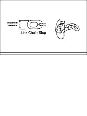
7.Check the chain for damage and elongation. Use the chain gauge on the bottom end of the chain as a guide. If the chain links do not fit inside the chain gauge, as shown in Figure 1, then the links have become elongated and the chain must be replaced.
 The load chain supplied with your JET lever hoist is designed, manufactured, and tested for proper fit and durability. Over a period of time, the chain may need to be replaced. For your own safety, use factory replacement chain only. Use of other than factory replacement chain may cause serious injury and/or damage to the lever hoist.
8.The top and bottom hooks on your JET lever hoist are designed to open to warn of an overload. It is important to check top and bottom hooks for proper opening. If the safety latch no longer contacts the hook opening, replace the hook. Another way to check the opening is by using the chain gauge. Position the gauge as in Figure 2.
7
Figure 1
Figure 2
9.If the gauge does not contact both sides of the hook, replace the hook. Never side load the top or bottom hook; this practice is dangerous and could lead to serious injury.
10.If the vertical angle at the neck of the bottom or top hook reaches 10°, replace the hook (see Figure 3).
Operation
1.Set the top hook securely.
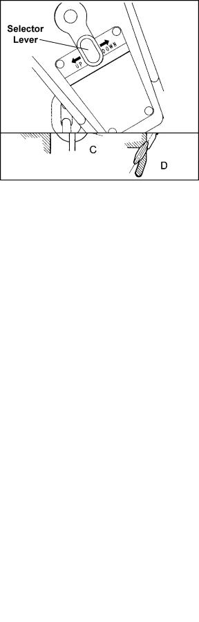
2.Center load on bottom hook correctly (Figure 4). Incorrect loading is dangerous to the operator, the lever hoist, and the load. Never load the hook in front of the safety latch (A, Figure 5). Never load the hook tip (B, Figure 5). Never load the hook off the centerline (C, Figure 5). Never load the hook sideways (D, Figure 5).
3.Place the selector lever on the handle in the center neutral position (Figure 6) so that the chain free-wheels. Note: Chain will only free-wheel when there is no load. Take up slack by pulling on loose or free end, or by turning handwheel.
4.Move selector lever to the up position (see Figure 6). Ratchet handle to raise or pull load. Do not overload the lever hoist.
5.To release or lower load, turn selector lever on handle to the down position (see Figure 6) and ratchet the handle.
Figure 3
Figure 4
Figure 5
Figure 6
8
 Loading...