


 Loading...
JET 350018, 350017, 350127, 350129, 350119 User Manual
...Operating Instructions and Parts Manual
JMD-15/18/18PFN Mill/Drill Machine
(JMD-18 shown with optional CS-18 stand)
JET |
|
427 New Sanford Road |
Part No. M-350020 |
LaVergne, Tennessee 37086 |
|
Ph.: 800-274-6848 |
Revision G 06/2015 |
www.jettools.com |
Copyright © 2015 JET |

1.0 Warranty and Service
JET warrants every product it sells against manufacturers’ defects. If one of our tools needs service or repair, please contact Technical Service by calling 1-800-274-6846, 8AM to 5PM CST, Monday through Friday.
Warranty Period
The general warranty lasts for the time period specified in the literature included with your product or on the official JET branded website.
•JET products carry a limited warranty which varies in duration based upon the product. (See chart below)
•Accessories carry a limited warranty of one year from the date of receipt.
•Consumable items are defined as expendable parts or accessories expected to become inoperable within a reasonable amount of use and are covered by a 90 day limited warranty against manufacturer’s defects.
Who is Covered
This warranty covers only the initial purchaser of the product from the date of delivery.
What is Covered
This warranty covers any defects in workmanship or materials subject to the limitations stated below. This warranty does not cover failures due directly or indirectly to misuse, abuse, negligence or accidents, normal wear-and-tear, improper repair, alterations or lack of maintenance.
Warranty Limitations
Woodworking products with a Five Year Warranty that are used for commercial or industrial purposes default to a Two Year Warranty. Please contact Technical Service at 1-800-274-6846 for further clarification.
How to Get Technical Support
Please contact Technical Service by calling 1-800-274-6846. Please note that you will be asked to provide proof of initial purchase when calling. If a product requires further inspection, the Technical Service representative will explain and assist with any additional action needed. JET has Authorized Service Centers located throughout the United States. For the name of an Authorized Service Center in your area call 1-800-274-6846 or use the Service Center Locator on the JET website.
More Information
JET is constantly adding new products. For complete, up-to-date product information, check with your local distributor or visit the JET website.
How State Law Applies
This warranty gives you specific legal rights, subject to applicable state law.
Limitations on This Warranty
JET LIMITS ALL IMPLIED WARRANTIES TO THE PERIOD OF THE LIMITED WARRANTY FOR EACH PRODUCT. EXCEPT AS STATED HEREIN, ANY IMPLIED WARRANTIES OF MERCHANTABILITY AND FITNESS FOR A PARTICULAR PURPOSE ARE EXCLUDED. SOME STATES DO NOT ALLOW LIMITATIONS ON HOW LONG AN IMPLIED WARRANTY LASTS, SO THE ABOVE LIMITATION MAY NOT APPLY TO YOU.
JET SHALL IN NO EVENT BE LIABLE FOR DEATH, INJURIES TO PERSONS OR PROPERTY, OR FOR INCIDENTAL, CONTINGENT, SPECIAL, OR CONSEQUENTIAL DAMAGES ARISING FROM THE USE OF OUR PRODUCTS. SOME STATES DO NOT ALLOW THE EXCLUSION OR LIMITATION OF INCIDENTAL OR CONSEQUENTIAL DAMAGES, SO THE ABOVE LIMITATION OR EXCLUSION MAY NOT APPLY TO YOU.
JET sells through distributors only. The specifications listed in JET printed materials and on official JET website are given as general information and are not binding. JET reserves the right to effect at any time, without prior notice, those alterations to parts, fittings, and accessory equipment which they may deem necessary for any reason whatsoever. JET® branded products are not sold in Canada by JPW Industries, Inc.
Product Listing with Warranty Period
90 Days – Parts; Consumable items
1 Year – Motors; Machine Accessories
2 Year – Metalworking Machinery; Electric Hoists, Electric Hoist Accessories; Woodworking Machinery used for industrial or commercial purposes
5 Year – Woodworking Machinery
Limited Lifetime – JET Parallel clamps; VOLT Series Electric Hoists; Manual Hoists; Manual Hoist Accessories; Shop Tools; Warehouse & Dock products; Hand Tools; Air Tools
NOTE: JET is a division of JPW Industries, Inc. References in this document to JET also apply to JPW Industries, Inc., or any of its successors in interest to the JET brand.
2
2.0 Table of contents
Section |
Page |
|||
1.0 |
Warranty and Service..................................................................................................................................... |
2 |
||
2.0 |
|
Table of contents............................................................................................................................................ |
3 |
|
3.0 |
Warnings ........................................................................................................................................................ |
4 |
||
4.0 |
|
Specifications ................................................................................................................................................. |
5 |
|
5.0 |
|
Contents of Shipping Container ..................................................................................................................... |
6 |
|
6.0 |
|
Unpacking and Clean-up................................................................................................................................ |
6 |
|
7.0 |
|
Assembly........................................................................................................................................................ |
7 |
|
8.0 |
|
Installation ...................................................................................................................................................... |
7 |
|
9.0 |
|
Lubrication...................................................................................................................................................... |
8 |
|
10.0 |
Electrical Connections.................................................................................................................................. |
8 |
||
11.0 |
Controls........................................................................................................................................................ |
9 |
||
12.0 Adjustments ............................................................................................................................................... |
10 |
|||
12.1 |
Changing Spindle Speeds...................................................................................................................... |
10 |
||
12.2 |
Arbor Replacement ................................................................................................................................ |
11 |
||
12.3 |
Gib Adjustment....................................................................................................................................... |
12 |
||
12.4 |
Power Feed Operation (JMD-18PFN only) ............................................................................................ |
12 |
||
12.5 |
Adjusting Spindle Return Spring ............................................................................................................ |
12 |
||
13.0 Replacement Parts..................................................................................................................................... |
13 |
|||
13.1.1 JMD-15 Head Assembly – Exploded View.......................................................................................... |
13 |
|||
13.1.2 JMD-15 Head Assembly – Parts List................................................................................................... |
14 |
|||
13.2.1 JMD-15 Table, Base, and Column Assembly – Exploded View.......................................................... |
17 |
|||
13.2.2 JMD-15 Table, Base, and Column Assembly – Parts List................................................................... |
17 |
|||
13.3.1 JMD-18/18PFN Head Assembly – Exploded View.............................................................................. |
19 |
|||
13.3.2 JMD-18/18PFN Head Assembly – Parts List ...................................................................................... |
20 |
|||
13.4.1 JMD-18 Table, Base, and Column Assembly – Exploded View.......................................................... |
24 |
|||
13.4.2 JMD-18 Table, Base, and Column Assembly – Parts List................................................................... |
24 |
|||
13.5.1 JMD-18PFN Power Feed Assembly – Exploded View........................................................................ |
27 |
|||
13.5.2 JMD-18PFN Power Feed Assembly – Parts List................................................................................. |
28 |
|||
14.0 |
Electrical Connections................................................................................................................................ |
30 |
||
14.1 |
Wiring Diagram: JMD-15 Only................................................................................................................ |
30 |
||
14.2 |
Wiring Diagram: JMD-18 Only................................................................................................................ |
31 |
||
3

3.0 Warnings
Read and understand the entire contents of this manual before attempting set-up or operation of this mill/drill.
1.This machine is designed and intended for use by properly trained and experienced personnel only. If you are not familiar with the proper safe use of mill/drills, do not use this machine until proper training and knowledge has been obtained.
2.Keep guards in place. Safety guards must be kept in place and in working order.
3.Remove adjusting keys and wrenches.
Before turning on machine, check to see that any adjusting wrenches are removed from the tool.
4.Reduce the risk of unintentional starting.
Make sure switch is in the OFF position before plugging in the tool.
5.Do not force tools. Always use a tool at the rate for which it was designed.
6.Use the right tool. Do not force a tool or attachment to do a job for which it was not designed.
7.Maintain tools with care. Keep tools sharp and clean for best and safest performance. Follow instructions for lubrication and changing accessories.
8.Always disconnect the tool from the power source before adjusting or servicing.
9.Check for damaged parts. Check for alignment of moving parts, breakage of parts, mounting, and any other condition that may affect the tools operation. A guard or any part that is damaged should be repaired or replaced.
10.Turn power off. Never leave a tool unattended. Do not leave a tool until it comes to a complete stop.
11.Keep work area clean. Cluttered areas and benches invite accidents.
12.Do not use in a dangerous environment.
Do not use power tools in damp or wet locations, or expose them to rain. Keep work area well lighted.
13.Keep children and visitors away. All visitors should be kept a safe distance from the work area.
14.Make the workshop child proof. Use padlocks, master switches, and remove starter keys.
15.Wear proper apparel. Loose clothing, gloves, neckties, rings, bracelets, or other jewelry may get caught in moving parts. Non-slip footwear is recommended. Wear protective hair covering to contain long hair. Do not wear any type of glove.
16.Always use safety glasses. Every day glasses only have impact resistant lenses; they are not safety glasses.
17.Do not overreach. Keep proper footing and balance at all times.
18.Do not place hands near the cutterhead while the machine is operating.
19.Do not perform any set-up work while machine is operating.
20.Read and understand all warnings posted on the machine.
21.This manual is intended to familiarize you with the technical aspects of this mill/drill.
It is not, nor was it intended to be, a training manual.
22.Failure to comply with all of these warnings may result in serious injury.
23.Some dust created by power sanding, sawing, grinding, drilling and other construction activities contains chemicals known to cause cancer, birth defects or other reproductive harm. Some examples of these chemicals are:
•Lead from lead based paint
•crystalline silica from bricks and cement and other masonry products, and
•arsenic and chromium from chemicallytreated lumber.
Your risk from those exposures varies, depending on how often you do this type of work. To reduce your exposure to these chemicals: work in a well ventilated area, and work with approved safety equipment, such as those dust masks that are specifically designed to filter out microscopic particles
4
4.0 Specifications
|
JMD-15 |
JMD-18 |
JMD-18PFN |
|
|
|
|
|
|
Stock No. |
350017 |
350018 |
350020 |
|
Drilling Capacity |
1” |
1-1/4” |
1-1/4” |
|
Face Mill Capacity |
2-1/2” |
3” |
3” |
|
End Mill Capacity |
1/2” |
3/4” |
3/4" |
|
Swing |
14-1/2” |
15-7/8” |
15-7/8” |
|
Maximum Distance Spindle to |
15” |
18” |
26” |
|
Table |
||||
|
|
|
||
Spindle Taper |
R-8 |
R-8 |
R-8 |
|
Spindle Travel |
3-1/2” |
5” |
5” |
|
Quill Diameter |
2-1/2” |
3” |
3” |
|
Head Swivel |
360° |
360° |
360° |
|
Column Diameter |
3-5/8” |
4-1/2” |
4-1/2” |
|
Number of Power Downfeeds |
---- |
---- |
3 |
|
Range of Power Downfeeds |
---- |
---- |
0.0047”, 0.007”, 0.001” |
|
Number of Spindle Speeds |
12 |
12 |
12 |
|
Range of Spindle Speeds |
110-2,580 RPM |
150-3,000 RPM |
150-3,000 RPM |
|
Maximum Table Travel |
14” |
20-1/2” |
20-1/2” |
|
Cross Travel |
6” |
7” |
7” |
|
Working Surface of Table |
7-1/2” x 23” |
9-1/2” x 31-3/4” |
9-1/2” x 31-3/4” |
|
Number of T-Slots |
4 |
4 |
4 |
|
T-Slot Size |
9/16” |
5/8” |
5/8” |
|
T-Slot Centers |
1-1/2” |
2-1/8” |
2-1/8” |
|
Overall Dimensions |
36-1/2”L x 37-1/2”W x |
42-1/2”L x 39-3/4”W x 43- |
42-1/2”L x 39-3/4”W x 51- |
|
35-1/2”H |
1/2”H |
1/2”H |
||
|
||||
Base Dimensions |
12-1/2” x 19-3/4” |
15-3/4” x 23-3/4” |
15-3/4” x 23-3/4” |
|
|
1HP, 1PH, 14/7A, 60Hz |
2HP, 1PH, 26/13A, 60Hz |
2HP, 1PH, 26/13A, 60Hz |
|
Motor (UL listed) |
115/230V |
115/230V |
115/230V |
|
|
(prewired 115V) |
(prewired 115V) |
(prewired 115V) |
|
Net Weight (approx.) |
440 lbs. |
660 lbs. |
700 lbs. |
|
Shipping Weight (approx.) |
540 lbs. |
760 lbs. |
800 lbs. |
The specifications in this manual are given as general information and are not binding. JET reserves the right to effect, at any time and without prior notice, changes or alterations to parts, fittings, and accessory equipment deemed necessary for any reason whatsoever.
5

5.0Contents of Shipping Container
1 Mill/Drill Machine
Accessory Package:
11/2” Drill Chuck w/ Chuck Key
1Adjustable Carbide Facemill
1Facemill Arbor
1Bolts, Nuts, and Washers to Attach Vise to Table
12-1/2” Angle Vise (JMD-15)
13” Angle Vise (JMD-18/18PFN)
3Handle Rods (JMD-15/18)
3Rubber Knobs (JMD-15/18)
2Rubber Knobs (JMD-18PFN)
13/8”x1” Hex Socket Cap Screw
13/8” Washer
1Crank Body (Installed)
1Crank Handle
1Spindle Guard Assembly
13mm Hex Wrench
14mm Hex Wrench
15mm Hex Wrench
123mm Wrench (JMD-18/18PFN)
3Hand Wheels w/ Handles
1 Can Touch-Up Paint
1 Owner’s Manual
1 Warranty Card
1Lifting Hook (installed 18in. model only)
6.0Unpacking and Clean-up
1.Finish removing the crate from the mill/drill. Unbolt the machine from the crate bottom. Report shipping damage, if any, to your distributor.
2.Clean all rust protected surfaces using a mild commercial solvent, kerosene or diesel fuel. Do not use paint thinner, gasoline, or lacquer thinner. These will damage painted
surfaces. Cover all cleaned surfaces with a light film of Mobil DTE® Oil Heavy Medium.
3.JMD-18/18PFN only: Open the belt cover and thread the lifting hook into the head.
4.Carefully lift the mill/drill with properly rated equipment to a sturdy stand or work bench. (Use the lifting hook on the JMD-18/18PFN. On the JMD-15, place straps beneath the head, next to the column.
5.Remove the lifting hook (JMD-18/18PFN).
6
Tools Needed for Assembly
8” Adjustable Wrench or 1/4” to 1-1/4” Combination Wrench Set
(JMD-18 shown with optional CS-18 stand)
(JMD-18/18PFN only)

7.0 Assembly
1.Screw rubber handles (A, Fig. 1) onto handle rod (B, Fig. 1). Screw handle rod into downfeed hub (C, Fig. 1) and tighten. Flat spot on rod accommodates a combination or adjustable wrench. Note: Handle shafts are already installed into hub on JMD-18PFN.
2.Repeat for other two rod assemblies.
3.Slide crank (D, Fig. 2) onto shaft and tighten set screw (E, Fig. 2). Be sure set screw seats on flat part of shaft.
4.Thread handle (F, Fig. 2) into crank and tighten.
5.Slide handwheel (G, Fig. 3) onto table handwheel shaft and tighten set screw. Insert handle (H, Fig. 3) into handwheel and tighten.
6.Repeat for two remaining table hand wheels.
7.Install spindle guard assembly (Figure 3a).
8.0 Installation
 Machine is heavy! Use an appropriate lifting device and use extreme caution when moving the machine to its final location. Failure to comply may cause serious injury.
1.The location for the mill/drill should be well lit, dry, and have room enough to allow the head to rotate 360°.
2.Before bolting the mill/drill to a bench or stand, the unit must be level in both directions. Place a level on the table in both directions.
3.If the table is not level, shim under the low corner(s) until level. Tighten the fastening bolts. Check for level again. Adjust as necessary until the mill/drill is level after the fastening hardware has been tightened.
7
9.0 Lubrication
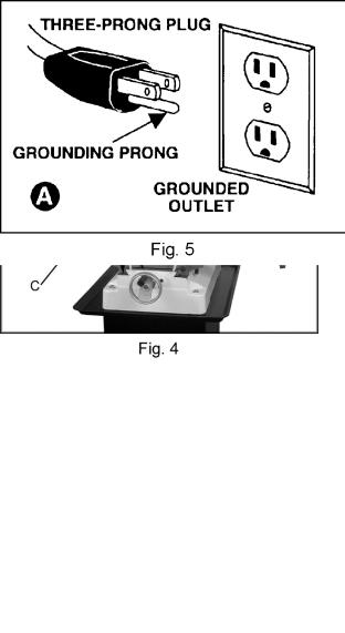
Lubricate ball oilers (A, Fig. 4) by the X/Y-axis hand wheels, the oiler at the raising/lowering crank handle, and the oiler on front of the bed once daily with Mobil DTE® Oil Heavy Medium.
Lubricate the ways (B, Fig. 4) once daily with Mobil DTE® Oil Heavy Medium.
If the head does not rise or lower smoothly, apply Mobilith AW2 to the rack, and Mobil DTE® Oil Heavy Medium to the column.
If the feed handles do not turn smoothly, apply Mobilith AW2 to the cross and longitudinal lead screws (C, Fig. 4). Access the cross lead screw by moving the table forward and removing the way cover.
The spindle bearings are permanently sealed and require no lubrication.
10.0 Electrical Connections
 A qualified electrician must make all electrical connections. Failure to comply may cause serious injury.
Before making any electrical connections, make sure the power source available is compatible with the machine. Also, turn the machine OFF using the buttons or switch at the front of the machine before connecting to the power source.
The JMD Mill/Drills are rated at 115/230V and come from the factory prewired at 115V. The mill/drill comes with a plug designed for use on a circuit with an outlet that looks like the one in Fig. 5, and has a grounding prong as illustrated in Fig. 5.
To switch the Mill/Drill to 230V operation:
1.Disconnect machine from power source.
2.Remove junction box cover on the motor.
3.Change the wires according to the diagram on the inside of the junction box cover, and reinstall junction box cover.
4.Replace thermal relay with one rated for 230V operation (see parts list).
5.Change power plug to one rated 230V, or hard wire the power cord.
Make sure the mill/drill is properly grounded.
8

11.0 Controls
Longitudinal Hand Wheels: (X-axis) (A, Fig. 6)
Located on either side of the table. Moves table side to side.
Cross Feed Hand Wheel: (Y-axis) (B, Fig. 6)
Located on the front of the base. Moves table toward, or away from the column.
Adjustable Table Stops: (C, Fig. 6)
Located on table front. Adjust to stop table at any setting along the longitudinal axis.
Table Locks: (D & E, Fig. 6)
Longitudinal table locks are located on front of the table. Cross-feed table locks are located on the right side under the table. Turn clockwise to lock.
Depth Stop:
JMD-15: (K, Fig. 8) located on the left side. Set nuts for desired depth stop.
JMD-18: (F, Fig. 7) located in the front. Push in the button on the front of the quick adjust stop and move to desired position.
JMD-18PFN: Set the depth stop on the power down feed assembly to desired depth for repetitive drilling to the same depth, see “Power Feed Operation” on page 12.
Downfeed Handles: (G, Fig. 7)
Located on the right side of the head casting. Counter-clockwise movement advances the quill toward the table. Return spring retracts the handles. Note: the knob (I, Fig. 7) must be loose for the downfeed handles to work.
Fine Feed Hand Wheel: (H, Fig. 7)
Located on the front of the head casting. To activate, tighten the knob (I Fig. 7) and turn the power feed speed range dial (J, Fig. 7) to zero.
9
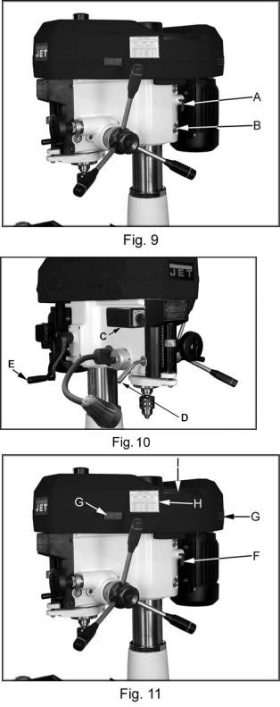
Motor Mount Lock Lever: (A, Fig. 9)
Located on the right side of the head casting. Locks and unlocks the motor mounting plate enabling the user to tension v-belts.
Head Pivot Lock: (B, Fig. 9)
Located on the right rear of the head casting. Loosen two hex nuts to rotate the head 360°. Tighten two hex nuts to lock the head in position.
On-Off Switch: (C, Fig. 10)
Turns spindle on and off, and changes spindle direction. Allow the spindle to come to a stop before reversing rotation.
Quill Lock Handle: (D, Fig. 10)
Located on the front left of the head casting. Turn clockwise to lock the quill in the desired position. Turn counter-clockwise to release.
Head Elevating Crank Handle: (E, Fig. 10)
Located at left rear of head casting. Loosen head pivot lock nuts (B, Fig. 9) and turn handle clockwise to raise head on the column and counter-clockwise to lower head.
 This machine is designed and intended for use by properly trained and experienced personnel only. If you are not familiar with the proper and safe use of mill/drills, do not use this machine until proper training and knowledge have been obtained. Failure to comply may cause serious injury.
12.0Adjustments
12.1Changing Spindle Speeds
1.Disconnect the machine from the power source, unplug.
2.Loosen the motor mount lock lever (F, Fig,
11)and pull the motor toward the head casting to release tension on the v-belts.
3.Release two latches (G, Fig. 11) on belt cover and slide pulley guard open (I, Fig. 11).
10
Loading...