


725001K
Table of contents
 Loading...
This .pdf document is bookmarked
Operating Instructions and Parts Manual
ProShop II™ 10-inch Table Saw
Model JPS2-115, JPS2-230
JET
427 New Sanford Road
LaVergne, Tennessee 37086 Part No. M-725000
Ph.: 800-274-6848 Edition 1 09/2017
www.jettools.com Copyright © 2017 JET
shown with cast wings, 52” rail set, and extension table

1.0 IMPORTANT SAFETY INSTRUCTIONS
WARNING: Read all safety warnings, instructions,
illustrations and specifications provided with this
power tool. Failure to follow all instructions listed
below may result in electric shock, fire and/or
serious injury.
Save all warnings and instructions for future
reference.
1.1 General Safety Warnings
Work area safety
•
Keep work area clean and well lit.
dark areas invite accidents.
•
Do not operate power tools in explosive
atmospheres, such as in the presence of
flammable liquids, gases or dust.
create sparks which may ignite the dust or fumes.
•
Keep children and bystanders away while
operating a power tool.
you to lose control.
Distractions can cause
Electrical safety
•
Power tool plugs must match the outlet. Never
modify the plug in any way. Do not use any
adapter plugs with earthed (grounded) power
Unmodified plugs and matching outlets will
tools.
reduce risk of electric shock.
•
Avoid body contact with earthed or grounded
surfaces, such as pipes, radiators, ranges and
refrigerators.
shock if your body is earthed or grounded.
•
Do not expose power tools to rain or wet
conditions.
increase the risk of electric shock.
•
Do not abuse the cord. Never use the cord for
carrying, pulling or unplugging the power tool.
Keep cord away from heat, oil, sharp edges or
moving parts.
increase the risk of electric shock.
•
When operating a power tool outdoors, use an
extension cord suitable for outdoor use.
cord suitable for outdoor use reduces the risk of
electric shock.
•
If operating a power tool in a damp location is
unavoidable, use a GFCI (ground fault circuit
interruptor) protected supply.
reduces the risk of electric shock.
There is an increased risk of electric
Water entering a power tool will
Damaged or entangled cords
Cluttered or
Power tools
Use of a
Use of a GFCI
Personal safety
•
Stay alert, watch what you are doing and use
common sense when operating a power tool. Do
not use a power tool while y ou are tired or under
the influence of drugs, alcohol or medication.
moment of inattention while operating power tools
may result in serious personal injury.
•
Use personal protective equipment. Always
wear eye protection.
dust mask, non-skid safety shoes, hard hat, or
hearing protection used for appropriate conditions
will reduce personal injuries.
•
Prevent unintentional starting. Ensure the
switch is in the off-position before connecting to
power source and/or battery pack, picking up or
carrying the tool.
finger on the switch or energising power tools that
have the switch on invites accidents.
•
Remove any adjusting key or wrench before
turning the powe r tool on.
attached to a rotating part of the power tool may
result in personal injury.
•
Do not overreach. Keep proper footing and
balance at all times.
the power tool in unexpected situations.
•
Dress properly. Do not wear loose clothing or
jewelry. Keep your hair, clothing and gloves
away from moving parts.
long hair can be caught in moving parts.
•
If devices are provided for the connection of
dust extraction and collection facilities, ensure
these are connected and properly used.
dust collection can reduce dust-related hazards.
•
Do not let familiarity gained from frequent use of
tools allow you to become complacent and
ignore tool safety principles.
can cause severe injury within a fraction of a
second.
Protective equipment such as
Carrying power tools with your
A wrench or a key left
This enables better control of
Loose clothes, jewelry or
A careless action
Power tool use and care
•
Do not force the power tool. Use the correct
power tool for your application.
power tool will do the job better and safer at the rate
for which it was designed.
•
Do not use the power tool if the switch does not
turn it on and off.
controlled with the switch is dangerous and must be
repaired.
•
Disconnect the plug from the power source
and/or remove the battery pack, if detachable,
from the power tool before making any
adjustments, changing accessories, or storing
power tools.
reduce the risk of starting the power tool
accidentally.
Any power tool that cannot be
Such preventive safety measures
The correct
A
Use of
2

•
Store idle power tools out of the reach of
children and do not allow persons unfamiliar
with the power tool or these instructions to
operate the power tool.
dangerous in the hands of untrained users.
•
Maintain power tools and accessories. Check
for misalignment or binding of moving parts,
breakage of parts and any other condition that
may affect the power tool’s operation. If
damaged, have the power tool repaired before
Many accidents are caused by poorly
use.
maintained power tools.
•
Keep cutting tools sharp and clean.
maintained cutting tools with sharp cutting edges
are less likely to bind and are easier to control.
•
Use the power tool, accessories and tool bits
etc. in accordance with these instructions,
taking into a ccount the worki ng conditions and
the work to be pe rformed.
for operations different from those intended could
result in a hazardous situation.
•
Keep handles and grasping surfaces dry, clean
and free from oil and grease.
and grasping surfaces do not allow for safe handling
and control of the tool in unexpected situations.
Service
•
Have your power tool serviced by a qualified
repair person using only identical replacement
This will ensure that the safety of the power
parts.
tool is maintained.
Power tools are
Properly
Use of the power tool
Slippery handles
1.2 Specific Safety Warnings for
Table Saws
Guarding related warnings
•
Keep guards in place. Guards must be in
working order an d be pro pe rl y mou nt ed.
that is loose, damaged, or is not functioning
correctly must be repaired or replaced.
•
Always use saw blade guard, riving knife and
anti-kickback pawls for every through-cutting
operation.
the saw blade cuts completely through the thickness
of the workpiece, the guard and other safety
devices help reduce the risk of injury.
•
Immediately reattach the guarding system after
completing an operation (such as rabbeting,
dadoing or resawing cuts) which requires
removal of the guard, riving knife and/or antikickback pawls.
kickback pawls help to reduce the risk of injury.
•
Make sure the saw blade is not contacting the
guard, riving knife or the workpiece before the
switch is turned on.
items with the saw blade could cause a hazardous
condition.
•
Adjust the riving knife as described in this
instruction manual.
For through-cutting operations where
The guard, riving knife, and anti-
Inadvertent contact of these
Incorrect spacing, positioning
A guard
and alignment can make the riving knife ineffective
in reducing the likelihood of kickback.
•
For the riving knife and anti-kickback pawls to
work, they must be engaged in the workpiece.
The riving knife and anti-kickback pawls are
ineffective when cutting workpieces that are too
short to be engaged with the riving knife and antikickback pawls. Under these conditions a kickback
cannot be prevented by the riving knife and antikickback pawls.
•
Use the appropriate saw blade for the riving
knife.
For the riving knife to function properly, the
saw blade diameter must match the appropriate
riving knife and the body of the saw blade must be
thinner than the thickness of the riving knife and the
cutting width of the saw blade must be wider than
the thickness of the riving knife.
Cutting proced ure s wa rni n gs
•
DANGER: Never place your fingers or hands in
the vicinity or in line with the saw blade.
moment of inattention or a slip could direct your
hand towards the saw blade and result in serious
personal injury.
•
Feed the workpiece into the saw blade or cutter
only against the direction of rotation.
the workpiece in the same direction that the saw
blade is rotating above the table may result in the
workpiece, and your hand, being pulled into the saw
blade.
•
Never use the miter gauge to feed the workpiece
when ripping and do not use the rip fe nce as a
length stop when cross cutting with the miter
Guiding the workpiece with the rip fence
gauge.
and the miter gauge at the same time increases the
likelihood of saw blade binding and kickback.
•
When ripping, always apply the workpiece
feeding force between the fence and the saw
blade. Use a push stick when the distance
between the fence and the saw blade is less
than 150 mm (6 in.), and use a push block when
this distance is less than 50 mm (2 in.).
helping” devices will keep your hand at a safe
distance from the saw blade.
•
Use only the push stick provided by the
manufacturer or constructed in accordance with
the instructions.
distance of the hand from the saw blade.
•
Never use a damaged or cut push stick.
damaged push stick may break causing your hand
to slip into the saw blade.
•
Do not perform any operation “freehand”.
Always use either the rip fence or the miter
gauge to position and guide the workpiece.
“Freehand” means using your hands to support or
guide the workpiece, in lieu of a rip fence or mitre
gauge. Freehand sawing leads to misalignment,
binding and kickback.
This push stick provides sufficient
Feeding
A
“Work
A
3

•
Never reach around or over a rotating saw
Reaching for a workpiece may lead to
blade.
accidental contact with the moving saw blade.
•
Provide auxiliary workpiece support to the rear
and/or sides of the saw table for long and/or
wide workpieces to keep them level.
and/or wide workpiece has a tendency to pivot on
the table’s edge, causing loss of control, saw blade
binding and kickback.
•
Feed workpiece at an even pace. Do not bend or
twist the workpiece. If jamming occurs, turn the
tool off imme diately, unplug the tool then clear
the jam.
can cause kickback or stall the motor.
•
Do not remove pieces of cut-off material while
the saw is running.
trapped between the fence or inside the saw blade
guard and the saw blade pulling your fingers into
the saw blade. Turn the saw off and wait until the
saw blade stops before removing material.
•
Use an auxiliary fence in contact with the table
top when ripping workpieces less than 2 mm
thick.
fence and create a kickback.
Jamming the saw blade by the workpiece
The material may become
A thin workpiece may wedge under the rip
A long
Kickback causes and related warnings
Kickback is a sudden reaction of the workpiece due to a
pinched, jammed saw blade or misaligned line of cut in
the workpiece with respect to the saw blade or when a
part of the workpiece binds between the saw blade and
the rip fence or other fixed object.
Most frequently during kickback, the workpiece is lifted
from the table by the rear portion of the saw blade and is
propelled towards the operator.
Kickback is the result of saw misuse and/or incorrect
operating procedures or conditions and can be avoided
by taking proper precautions as given below.
•
Never stand directly in line with the saw blade.
Always position your body on the same side of
the saw blade as the fence.
the workpiece at high velocity towards anyone
standing in front and in line with the saw blade.
•
Never reach over or in back of the saw blade to
pull or to support the workpiece.
contact with the saw blade may occur or kickback
may drag your fingers into the saw blade.
•
Never hold and press the workpiece that is
being cut off against the rotating saw blade.
Pressing the workpiece being cut off against the
saw blade will create a binding condition and
kickback.
•
Align the fence to be parallel with the saw blade.
A misaligned fence will pinch the workpiece against
the saw blade and create kickback.
•
Use a featherboard to guide the workpiece
against the table and fence when making nonthrough cuts such as rabbeting, dadoing or
Kickback may propel
Accidental
resawing cuts
workpiece in the event of a kickback.
•
Use extra caution when making a cut into blind
areas of assembled workpieces.
saw blade may cut objects that can cause kickback.
•
Support lar ge pa nels t o minimiz e the risk of saw
blade pinching and kickback.
to sag under their own weight. Support(s) must be
placed under all portions of the panel overhanging
the table top.
•
Use extra caution when cutting a workpiece that
is twisted, knotted, warped or does not have a
straight edge to guide it with a miter gauge or
along the fence.
workpiece is unstable and causes misalignment of
the kerf with the saw blade, binding and kickback.
•
Never cut more than one workpiece, stacked
vertically or horizontally.
pick up one or more pieces and cause kickback.
•
When restarting the saw with the saw blade in
the workpiece, center the saw blade in the kerf
so that the saw teeth are not engaged in the
material.
workpiece and cause kickback when the saw is
restarted.
•
Keep saw blades clean, sharp, and with
sufficient set. Never use warped saw blades or
saw blades with cracked or broken teeth.
and properly set saw blades minimize binding,
stalling and kickback.
. A featherboard helps to control the
The protruding
Large panels tend
A warped, knotted, or twisted
The saw blade could
If the saw blade binds, it may lift up the
Sharp
Table saw operating procedure warnings
•
Turn off the ta ble sa w and dis connec t the power
cord when removing the table insert, changing
the saw blade or making adjustments to the
riving knife, anti-kickback pawls or saw blade
guard, and when the machine is left unatte nded.
Precautionary measures will avoid accidents.
•
Never leave the table saw running unattended.
Turn it off and don’t leave the tool until it comes
to a complete stop.
an uncontrolled hazard.
•
Locate the table saw in a well-lit and level area
where you can maintain good footing and
balance. It should be installed in an area that
provides enou gh room to easi ly handle the s ize
of your workpiece.
uneven slippery floors invite accidents.
•
Frequently clean and remove sawdust from
under the saw table and/or the dust collection
Accumulated sawdust is combustible and
device.
may self-ignite.
•
The table saw must be secured.
is not properly secured may move or tip over.
•
Remove tools, wood scraps, etc. from the table
before the table saw is turned on.
potential jam can be dangerous.
An unattended running saw is
Cramped, dark areas, and
A table saw that
Distraction or a
4

•
Always use saw blades with correct size and
shape (diamond versus round) of arbor holes.
Saw blades that do not match the mounting
hardware of the saw will run off-center, causing loss
of control.
•
Never use damaged or incorrect saw blade
mounting means such as flanges, saw blade
washers, bolts or nuts.
were specially designed for your saw, for safe
operation and optimum performance.
•
Never stand on the table saw, do not use it as a
stepping stool.
tool is tipped or if the cutting tool is accidentally
contacted.
•
Make sure that the saw blade is installed to
rotate in the proper direction. Do not use
grinding wheels, wire brushes, or abrasive
wheels on a table saw.
installation or use of accessories not recommended
may cause serious injury.
Serious injury could occur if the
These mounting means
Improper saw blade
Additional safety rules
•
This table saw is designed and intended for use by
properly trained and experienced personnel only. If
you are not familiar with the proper and safe
operation of a table saw, do not use until proper
training and knowledge have been obtained.
•
Do not use this table saw for other than its intended
use. If used for other purposes, JET disclaims any
real or implied warranty and holds itself harmless
from any injury that may result from that use.
•
Do not wear gloves when operating a table saw.
•
WARNING: Drilling, sawing, sanding or machining
wood products generates wood dust and other
substances known to the State of California to
cause cancer. Avoid inhaling dust generated from
wood products or use a dust mask or other
safeguards to avoid inhaling dust generated from
wood products.
•
Wood products emit chemicals known to the State
of California to cause birth defects or other
reproductive harm. (California Health and Safety
Code Section 25249.6)
•
Blade should have minimum exposure during cuts.
Adjust blade to approximately 1/8” inch above
surface of workpiece.
Familiarize yourself with the following safety notices used in this manual:
This means that if precautions are not heeded, it may result in minor injury and/or possible
machine damage.
This means that if precautions are not heeded, it may result in serious or possibly fatal injury.
5

2.0 Table of contents
Section Page
1.0 IMPORTANT SAFETY INSTRUCTIONS ............................................................................................... 2
1.1 General Safety Warnings ................................................................................................................... 2
1.2 Specific Safety Warnings for Table Saws .......................................................................................... 3
2.0 Table of contents .................................................................................................................................... 6
3.0 About this manual .................................................................................................................................. 7
4.0 Table Saw terminology........................................................................................................................... 8
5.0 Specifications ......................................................................................................................................... 9
5.1 Kit configuratio ns .............................................................................................................................. 10
6.0 Setup and assembly ............................................................................................................................. 11
6.1 Shipping contents ............................................................................................................................. 11
6.2 Tools required for assembly ............................................................................................................. 12
6.3 Unpacking and cleanup .................................................................................................................... 12
6.4 Installing legs and levelers ............................................................................................................... 12
6.5 Extension wings ................................................................................................................................ 12
6.6 Handwheels ...................................................................................................................................... 13
6.7 Motor cover ....................................................................................................................................... 13
6.8 Rails and fence ................................................................................................................................. 13
6.9 Wood extension table ....................................................................................................................... 14
6.10 Switch bracket ................................................................................................................................ 14
6.11 Dust collection ................................................................................................................................ 14
6.12 Riving knife ..................................................................................................................................... 14
6.13 Anti-kickback pawls ........................................................................................................................ 14
6.14 Blade guard .................................................................................................................................... 15
6.15 Blade installation/replacement ....................................................................................................... 15
6.16 Low profile riving knife .................................................................................................................... 15
6.17 Table insert ..................................................................................................................................... 16
6.18 Miter gauge ..................................................................................................................................... 16
6.19 Tool storage .................................................................................................................................... 16
7.0 Electrical connections .......................................................................................................................... 16
7.1 GROUNDING INSTRUCTIONS ....................................................................................................... 16
7.2 Overload reset button ....................................................................................................................... 17
7.3 Extension cords ................................................................................................................................ 17
7.4 On/off switch lock-out ....................................................................................................................... 17
8.0 Adjustments ......................................................................................................................................... 18
8.1 Blade raising/tilt mechanism ............................................................................................................. 18
8.2 Adjusting blade tilt stops ................................................................................................................... 18
8.3 Riving knife alignment ...................................................................................................................... 19
8.4 Table to blade alignment .................................................................................................................. 20
8.5
Belt adjustment/replacement
9.0 Operations ............................................................................................................................................ 21
9.1 Kickbacks ......................................................................................................................................... 21
9.2 Rip sawing ........................................................................................................................................ 22
9.3 Resawing .......................................................................................................................................... 23
9.4 Crosscutting ...................................................................................................................................... 23
9.5 Bevel and miter operations ............................................................................................................... 24
10.0 Safety devices .................................................................................................................................... 25
11.0 User-maintenance .............................................................................................................................. 26
11.1 Cleaning ......................................................................................................................................... 26
11.2 Lubrication ...................................................................................................................................... 26
11.3 Additional servicing ........................................................................................................................ 26
12.0 Optional accessories .......................................................................................................................... 26
13.0 Troubleshooting JPS2 ProShop II ...................................................................................................... 27
14.0 Replacement Parts ............................................................................................................................. 27
14.1.1 Motor and Trunnion – Exploded View ......................................................................................... 28
............................................................................................................. 20
6

14.1.2 Motor and Trunnion – Parts List .................................................................................................. 29
14.2.1 Table and Cabinet– Exploded View ............................................................................................ 32
14.2.2 Table and Cabinet– Parts List ..................................................................................................... 33
14.3.1 Stand Assembly – Exploded View............................................................................................... 34
14.3.2 Stand Assembly – Parts List ....................................................................................................... 34
14.4.1 Switch Assembly – Exploded View ............................................................................................. 35
14.4.2 Switch Assembly – Parts List ...................................................................................................... 35
14.5.1 Blade Guard Assembly – Exploded View .................................................................................... 36
14.5.2 Blade Guard Assembly – Parts List............................................................................................. 37
14.6.1 Miter Gauge Assembly – Exploded View .................................................................................... 38
14.6.2 Miter Gauge Assembly – Parts List ............................................................................................. 38
15.0 Electrical Connections for JPS2 ......................................................................................................... 39
16.0 Warranty and Service......................................................................................................................... 40
3.0 About this manual
This manual is provided by JET covering the safe operation and maintenance procedures for a JET Model
JPS2 ProShop II™ Table Saw. This manual contains instructions on installation, safety precautions, general
operating procedures, maintenance instructions and parts breakdown. Your machine has been designed and
constructed to provide consistent, long-term operation if used in accordance with the instructions as set forth in
this document.
This manual is not intended to be an exhaustive guide to table saw operational methods, use of jigs or aftermarket accessories, choice of stock, etc. Additional knowledge can be obtained from experienced users, trade
articles, or website forums. Whatever accepted methods are used, always make personal safety a priority.
If there are questions or comments, please contact your local supplier or JET. JET can also be reached at our
web site: www.jettools.com.
Retain this manual for future reference. If the machine transfers ownership, the manual should accompany it.
Read and understand th e entire contents of this manual before attempting a ssembly
or operation. Failure to comply may cause serious injury.
Register your product using the mail-in card provided, or register online:
http://www.jettools.com/us/en/service-and-support/product-registration/
7

4.0 Table Saw terminology
Arbor: Metal shaft that connects the drive
mechanism to the blade.
Bevel Edge Cut: Tilt of the saw arbor and blade
between 0° and 45° to perform an angled cutting
operation.
Blade Guard: Mechanism mounted over the saw
blade to prevent accidental contact with the cutting
edge.
Crosscut: Sawing operation in which the miter
gauge is used to cut across the grain of the
workpiece.
Dado Blade: Blade(s) used for cutting grooves and
rabbets. A stacked dado set can be used for wider
grooves.
Dado Cut: Flat bottomed groove in the face of the
workpiece made with a dado blade.
Featherboard: Device used to keep a board
against the rip fence or table, allowing the operator
to keep hands away from saw blade.
Freehand: Moving the workpiece into the blade
using only the hands, without a fixed positioning
device. (This is a dangerous, unacceptable
procedure on a table saw – always use appropriate
devices to feed the workpiece through the saw
blade during cutting operations.)
Kerf: The resulting cut or gap made by a saw
blade.
Kickback: An event in which the workpiece is lifted
up and thrown back toward an operator, caused
when a workpiece binds on the saw blade or
between the blade and rip fence (or other fixed
object). To minimize or prevent injury from
kickbacks, see the Operations section.
Miter Gauge: A component that controls the
workpiece movement while performing a crosscut
of various angles.
Non-Through Cut: A sawing operation that
requires the removal of the blade guard and
standard riving knife, resulting in a cut that does
not protrude through the top of the workpiece
(includes dado and rabbet cuts).
The blade guard and riving knife must be reinstalled after performing a non-through cut to
avoid accidental contact with the saw blade during
operation.
Parallel: Position of the rip fence equal in distance
at every point to the side face of the saw blade.
Perpendicular: 90° (right angle) intersection or
position of the vertical and horizontal planes such
as the position of the saw blade (vertical) to the
table surface (horizontal).
Push Board/Push Stick: An instrument, usually of
wood or plastic, used to safely push the workpiece
through the cutting operation by keeping the
operator’s hands at a distance.
Rabbet: A cutting operation that creates an
L-shaped channel along the edge of the board.
Rip Cut: A cut made along the grain of the
workpiece.
Riving Knife: A metal plate fixed relative to the
blade, which moves with the blade as cutting depth
is adjusted. Thus, it maintains not only the kerf
opening in the workpiece, but also the knife-to-
blade distance. A low-profile riving knife sits lower
than the top edge of the blade, for making a nonthrough cut.
Splitter (Spreader): A stationary metal plate to
which the blade guard is attached that maintains
the kerf opening in the workpiece during a cutting
operation. (JET table saws use the superior Riving
Knife system instead.)
Standard Kerf: 1/8" gap made with a standard
blade.
Straightedge: A tool used to check that a surface
is flat or parallel.
Through Sawing: A sawing operation in which the
workpiece thickness is completely sawn through.
Proper blade height usually allows 1/8" of the top
of blade to extend above the wood stock. Keep the
blade guard down, the anti-kickback pawls down,
and the riving knife in place over the blade.
8

5.0 Specifications
Table 1
Model number
Stock number – saw only
(see Table 2 below for kit configurations)
Motor and Electricals
Motor type Totally enclosed, fan cooled, induction
Horsepower 1.75 HP
Motor phase 1 PH
Motor voltage 120 V 230 V
Cycle 60Hz
Listed FLA (full load amps) 7.4 A 14.8 A
Motor speed 3450 RPM
Starting amps 36 A 18 A
Running amps (no load) 3.7 A 1.8 A
Start capacitor 200MFD 125VAC
Run capacitor
Power transfer belt
On/off switch Magnetic switch KJD17B (NVR type)
Power cord 14AWG x 3, 6 ft (183cm)
Plug provided 5-15P 6-15P
Recommended circuit size 1 15 A
Sound emission without load 2 80 dB at 30 in. (762mm) from blade
Arbor and blade
Arbor diameter 5/8 in. (15.88 mm)
Arbor speed 4000 RPM
Arbor lock included
Arbor wrench included
Blade included 10 in. (254 mm), 40 tooth
Maximum depth of cut at 90 degrees 3-1/8 in. (79 mm)
Maximum depth of cut at 45 degrees 2-1/8 in. (54 mm)
Maximum rip to right of blade 30 in. or 52 in.
Maximum rip to left of blade 13.5 in. (343 mm)
Blade height per one revolution of handwheel 5/32 in. (4 mm) at 90°; 7/64 in. (2.83 mm) at 45°
Dado maximum width 13/16 in. (20.6 mm)
Dado maximum diameter 8 in.
Blade tilt 45° left tilt
Table
Main table dimensions, L x W 20 x 27 in. (508 x 686 mm)
Table dimensions with wings, L x W 44 x 27 in. (1118 x 686 mm)
Table area in front of blade at maximum height 8.81 in. (223.83 mm)
Table height from floor, approximate 34-3/4 in. (883 mm)
Miter T-slot, W x D 3/4 x 3/8 in. (19 x 10 mm)
Edge bevel Front
Main materials
Main table Cast iron
Table insert Aluminum
Extension wings Cast iron or stamped steel
Base and legs Steel
Center trunnion Aluminum
Pulleys Steel
JPS2-115 JPS2-230
725000 725001
40μF 300VAC
9

Dust collection
Dust port outside diameter 4 in. (102 mm)
Recommended minimum extraction volume 400 CFM (0.5 CMM)
General Dimensions
Base footprint 23-1/2 x 24-1/2 in. (597 x 623 mm)
Assembled, with 30-in. rail set, L x W x H 60 x 40 x 43 in. (1524 x 1016 x 1090 mm)
Assembled, with 52-in. rail set, L x W x H 82 x 40 x 43 in. (2083 x 1016 x 1090 mm)
Shipping dimensions, saw only, L x W x H 30 x 29-3/4 x 29 in. (76 x 75.5 x 74.5 cm)
Weights
Saw only without wings – net weight 178 lbs (81 kg)
Saw only without wings – shipping weight 191.5 lbs (87 kg)
1
subject to local/national electrical codes.
2
The specified values are emission levels and are not necessarily to be seen as safe operating levels. As workplace
conditions vary, this information is intended to allow the user to make a better estimation of the hazards and risks
involved only.
L = length, W = width, H = height, D = depth
n/a = not applicable
The specifications in this manual were current at time of publication, but because of our policy of continuous
improvement, JET reserves the right to change specifications at any time and without prior notice, without incurring
obligations.
5.1 Kit configurations
Stock numbers
120V model 230V model
Proshop II saw only
Proshop II saw, 30” rip, cast wings 725000K 725002K
Proshop II saw, 30” rip, steel wings
Proshop II saw, 52” rip, cast wings, wood extension table
Proshop II saw, 52” rip, steel wings, wood extension table
Table 2
725000 725001
725004K 725006K
725001K 725003K
725005K 725007K
10
Read and understand all
assembly instructions before attempting
assembly. Failure to comply may cause serious
injury.
6.0 Setup and assembly
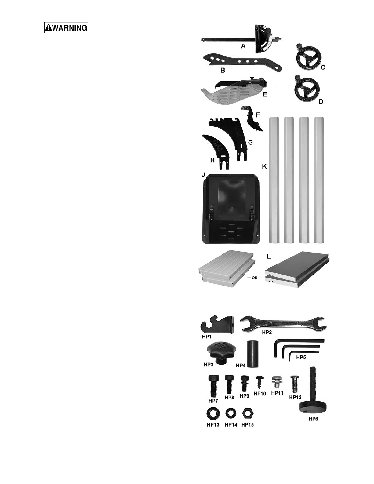
6.1 Shipping contents
See Figures 6-1 and 6-2.
NOTE: Some parts may have come pre-assembled
to the table saw.
1 Table saw with on/off switch (not shown)
1 Blade (preinstalled on saw)
1 Table insert (preinstalled on saw)
1 Arbor wrench (preinstalled on tool holder)
1 Miter gauge – A
1 Push stick – B
1 Handwheel, large mounting hole – C
1 Handwheel, small mounting hole – D
1 Guard assembly – E
1 Anti-kickback pawl assembly – F
1 Riving knife – G
1 Low profile riving knife – H
1 Motor cover – J
4 Legs – K
2 Extension wings – L
1 Operator’s manual (not shown)
1 Product registration card (not shown)
1 Hardware package
6.1.2 Hardware package
1 Storage hook – HP1
1 Open end wrench 11-13mm – HP2
1 Knob – HP3
1 Spacer – HP4
3 Hex wrenches, 2.5, 4, 5 mm – HP5
4 Levelers – HP6
8 Socket hd cap screws M8x20 – HP7
8 Socket hd cap screws M6x16 – HP8
1 Soc hd cap screw w/lock wshr M5x12 – HP9
2 Tapping screws M5x12 – HP10
2 Hex cap screws w/flat wshr M8x10 – HP11
4 Pan hd machine screws M6x16 – HP12
8 Flat washers M8 – HP13
12 Flat washers M6 – HP14
4 Hex nuts M8 – HP15
NOTE: Fence and rail assemblies with fasteners,
and wood extension tables and legs with fasteners,
are shipped in separate boxes.
Figure 6-1: Contents (not to scale)
11
Figure 6-2: Hardware (not to scale)
6.2 Tools required for assembly
Hex (Allen) wrenches: 4, 5, 6mm
Open end wrenches: 10, 13mm
Cross point (Phillips) screwdriver
Straight edge
Rubber mallet (or hammer with block of wood)
Level
Note: A ratchet wrench with sockets will speed
assembly time. Additional tools may be needed for
adjustments and/or assembly of fence and rails.
The main saw unit is heavy;
use an assistant or a hoist mechanism when
moving or turning it right side up.
6.3 Unpacking and cleanup
1. Remove all contents from shipping carton and
from inside of saw body. Do not discard carton
or packing material until saw is assembled and
running satisfactorily.
2. Inspect contents for shipping damage. Report
damage, if any, to your distributor.
3. Compare contents of shipping carton with the
contents list in this manual. Report shortages,
if any, to your distributor. Check machine first
to see if parts have been pre-installed.
4. Slide table saw off pallet onto cardboard or
pad to prevent scratching table surface. Keep
saw upside down.
Install both screws first, then tighten with 5mm
hex wrench. (Note: If more clearance is
needed to insert a screw, see sect. 6.6 to
temporarily mount a handwheel and tilt the
trunnion out of the way.)
2. Install four levelers with hex nuts (HP6/14).
3. Turn saw right-side up and allow the feet to
adjust to floor surface. Place a level on table,
and adjust the levelers as needed. Tighten hex
nuts up against leg with 10mm wrench to
secure setting.
6.5 Extension wings
See Figure 6-4.
Wings are available in cast iron or stamped steel.
Make sure mating surfaces are clean and free of
burrs.
Attach each extension wing to saw table using four
screws and washers (HP7/13). Do not fully tighten
yet.
Assembly Tip: If you are doing this without an
assistant, lift extension wing perpendicular to table
edge. Install a center screw and washer, and make
snug. Then pivot wing parallel to saw table to insert
remaining three screws.
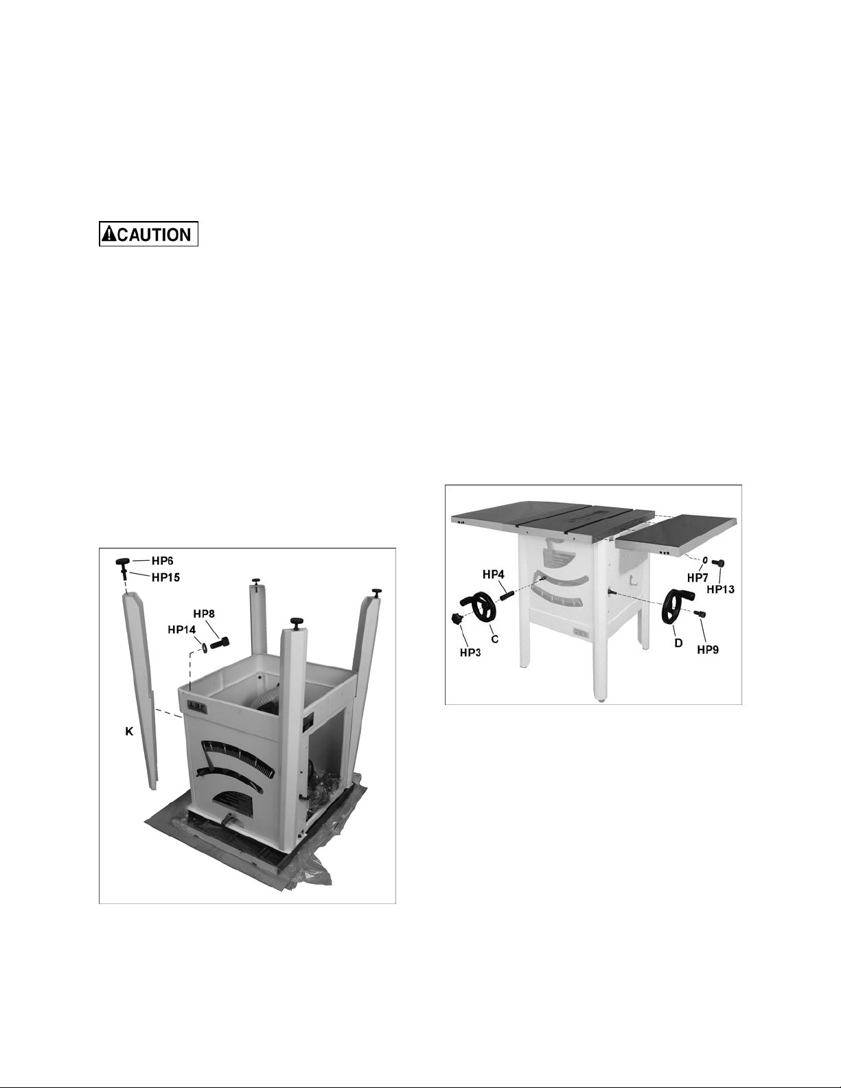
Figure 6-3
6.4 Installing legs and levelers
See Figure 6-3.
1. Mount legs (K) to cabinet using two M8 screws
with washers (HP8/13) into each leg as shown.
Figure 6-4
6.5.1 Leveling extension wings
Note: The following instructions show assembly of
the cast wings. The stamped steel wings may have
a tendency to sag until rails are installed, and may
need further leveling adjustments during rail
installation.
Level extension wings to saw table using a straight
edge. A metal straight edge is ideal, though a
carefully jointed board may also be used.
Two methods are described below: one using a
rubber mallet, the other using clamps on the table
edges.
12
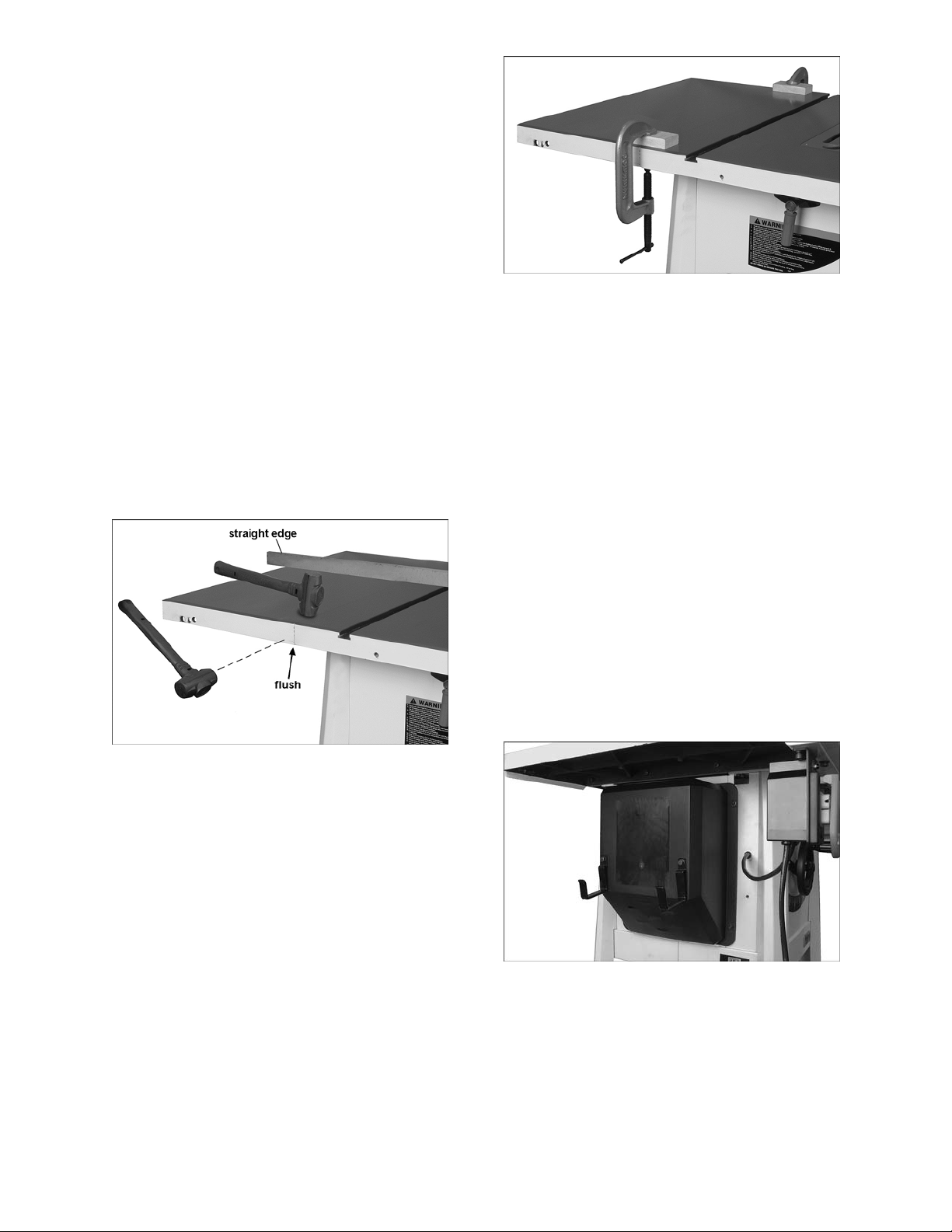
Method 1 (Figure 6-5):
1. Shift extension wing so it is slightly above saw
table surface.
2. Begin by tightening the screws beneath
extension wing that secure it to saw table.
Tighten these just enough to hold wing in
place but loose enough to change wing height
by tapping on it. (Tap with rubber mallet, or
hammer over a flat block of wood. Never use a
steel-faced hammer directly on the tables.)
3. Lay straight edge across saw table and
extension wing, extending it out past edge of
wing as shown in Figure 6-5.
4. Move straight edge to several places along
wing, as you continue to nudge wing level with
saw table. Also brush your fingertips over the
seam to ensure the transition feels smooth. As
each area of wing becomes flush with table,
tighten screw under that area. Continue until
all screws are fully tightened. NOTE: Make
sure front edge of wing remains flush with front
edge of saw table.
5. Repeat above steps for opposite extension
wing.
Figure 6-6: leveling extension wings, method 2
6.6 Handwheels
See Figure 6-4.
Note: The two handwheels look identical but have
different sized mounting holes.
1. On front of table saw, slide spacer (HP4,
Figure 6-4) onto shaft followed by handwheel
with large mounting hole (C). The flat side of
handwheel hole aligns with flat side on shaft.
2. Fasten in place by screwing in lock knob
(HP3).
Figure 6-5: leveling extension wings, method 1
Method 2 (Figure 6-6):
1. Follow steps 1 through 3 from Method 1.
2. Position clamps over seam, one at front, one
at back of table. Use a pad or flat block
beneath clamp jaw to prevent damage to table
surface. See Figure 6-6.
3. Tighten both clamps to align front and back
edges of tables. Make sure front edge of wing
remains flush with front edge of saw table.
4. Tighten screws incrementally, and position
straight edge at various places across seam,
especially checking at the center. Make further
adjustments as needed.
5. Fully tighten screws.
3. Slide handwheel with small mounting hole (D)
onto shaft on right side of table saw, aligning
flat side of hole with flat side on shaft.
4. Secure handwheel with lock washer and screw
(HP9), using 4mm hex wrench.
6.7 Motor cover
See Figure 6-7.
Install motor cover (J) with four pan head screws
and washers (HP12/14).
Figure 6-7
6.8 Rails and fence
To install front and rear rails and fence, consult
manual M-725005 which accompanies your fence
assembly, then proceed to sect. 6.11.
13
6.9 Wood extension table
To install the optional wood table, consult manual
M-725005, which accompanies your fence
assembly, then proceed to sect. 6.11.
6.10 Switch bracket
See Figure 6-8.
Use two screws with washers (HP-11) to secure
switch bracket to front rail.
Figure 6-8
6.11 Dust collection
Use of a dust collection system (not provided) is
strongly recommended during table saw operation.
It will help keep the shop clean, as well as prevent
potential health issues due to dust inhalation.
A dust collection system, with minimum capacity of
400 CFM (cubic feet per minute) should be
connected to the port via a 4-inch diameter hose
(not included) and secured with a hose clamp.
Note: Dryer vent hose is not acceptable for this
purpose.
An extensive line of JET dust collectors is
available; contact your dealer or visit our website
for information.
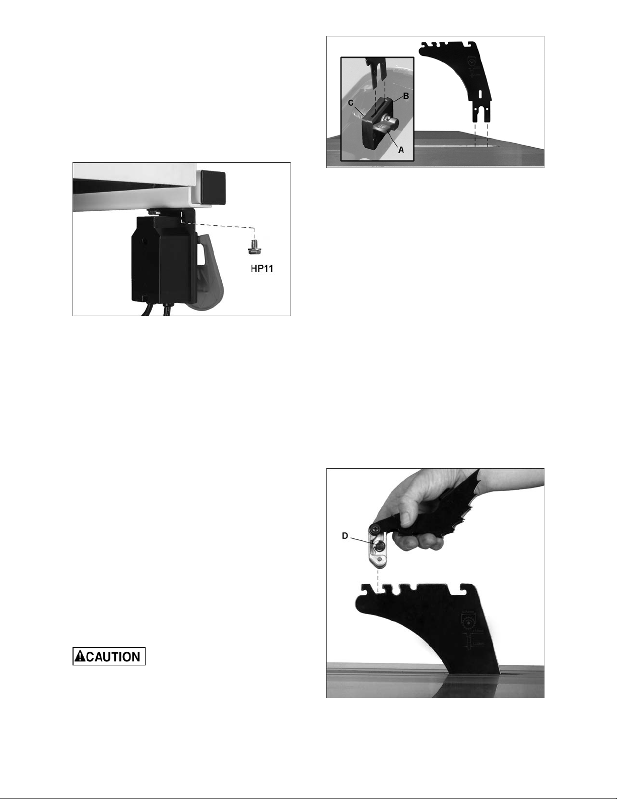
Figure 6-9
5. Slide tabs of riving knife (D) into slot between
the two blocks, all the way down onto
mounting stud.
6. Push down lever (A) to secure riving knife.
The clamping block (Figure 6-9) is adjusted at the
factory and no further adjustment of blade guard
and riving knife assembly should be necessary.
However, proper alignment is very important.
Before operating table saw, read sect. 8.3, Riving
knife alignment, to verify and follow the adjustment
procedure if necessary.
6.13 Anti-kickback pawls
See Figures 6-10 and 6-11.
1. Push and hold button (D) on opposite side of
the head to release the catch pin. Mount pawl
assembly straight down, in the location shown
in Figure 10.
2. Pivot head and push it downward (Figure 6-11)
until there is an audible click. Make sure you
hear the click to verify that pawl assembly is
secure.
6.12 Riving knife
See Figure 6-9.
1. Disconnect machine from power source.
2. Set saw blade to 90° (vertical) position and
raise it all the way (refer to sect. 8.1).
3. Remove table insert by rotating locking knob
(shown at M, Figure 6-14) and lift up insert
using finger hole.
Use care when working around
an installed blade.
4. Through the saw table opening, pull up lever
(A, Figure 6-9). The floating clamp block (B)
will move away from the fixed block (C),
leaving a gap.
14
Figure 6-10
Loading...