


BDB-1340A
Operation and Maintenance Instructions
Belt Drive Bench Lathe, 13x40-inch
Model BDB-1340A
(shown with optional 321443AK stand)
For Parts List and Electrical Diagrams, see document M-321357 A
JET
427 New Sanford Road
LaVergne, Tennessee 37086 Part No. M-321360A
Ph.: 800-274-6848 Revision G3 11/2014
www.jettools.com Copyright © 2014 JET
This .pdf document is bookmarked

2
Warranty and Service
JET warrants every product it sells against manufacturers’ defects. If one of our tools needs service or repair, please
contact Technical Service by calling 1-800-274-6846, 8AM to 5PM CST, Monday through Friday.
Warranty Period
The general warranty lasts for the time period specified in the literature included with your product or on the official
JET branded website.
• JET products carry a limited warranty which varies in duration based upon the product. (See chart below)
• Accessories carry a limited warranty of one year from the date of receipt.
• Consumable items are defined as expendable parts or accessories expected to become inoperable within a
reasonable amount of use and are covered by a 90 day limited warranty against manufacturer’s defects.
Who is Covered
This warranty covers only the initial purchaser of the product from the date of delivery.
What is Co vered
This warranty covers any defects in workmanship or materials subject to the limitations stated below. This warranty
does not cover failures due directly or indirectly to misuse, abuse, negligence or accidents, normal wear-and-tear,
improper repair, alterations or lack of maintenance. JET woodworking machinery is designed to be used with Wood.
Use of th ese ma chines in the processing of metal , pl asti cs, or oth er m aterial s may void the warranty. The exceptio ns
are acrylics and other natural items that are made specifically for wood turning.
Warranty Limitations
Woodworking products with a Five Year Warranty that are used for commercial or industrial purposes default to a
Two Year Warranty. Please contact Technical Service at 1-800-274-6846 for further clarification.
How to Get Technical Support
Please contact Technical Service by calling 1-800-274-6846. Please note that you will be asked to provid e pr o of
of initia l p u rch a s e whe n calling. If a product requires further inspection, the Technical Service representative will
explain and assist with any additional action needed. JET has Authorized Service Centers located throughout the
United States. For the name of an Authorized Service Center in your area call 1-800-274-6846 or use the Service
Center Locator on the JET website.
More Information
JET is constantly adding new products. For complete, up-to-date product information, check with your local distributor
or visit the JET website.
How State Law Appli es
This warranty gives you specific legal rights, subject to applicable state law.
Limitations on This Warranty
JET LIMITS ALL IMPLIED WARRANTIES TO THE PERIOD OF THE LIMITED WARRANTY FOR EACH PRODUCT.
EXCEPT AS STATED HEREIN, ANY IMPLIED WARRANTIES OF MERCHANTABILITY AND FITNESS FOR A
PARTICULAR PURPOSE ARE EXCLUDED. SOME STATES DO NOT ALLOW LIMITATIONS ON HOW LONG AN
IMPLIED WARRANTY LASTS, SO THE ABOVE LIMITATION MAY NOT APPLY TO YOU.
JET SHALL IN NO EVENT BE LIABLE FOR DEATH, INJURIES TO PERSONS OR PROPERTY, OR FOR
INCIDENTAL, CONTINGENT, SPECIAL, OR CONSEQUENTIAL DAMAGES ARISING FROM THE USE OF OUR
PRODUCTS. SOME STATES DO NOT ALLOW THE EXCLUSION OR LIMITATION OF INCIDENTAL OR
CONSEQUENTIAL DAMAGES, SO THE ABOVE LIMITATION OR EXCLUSION MAY NOT APPLY TO YOU.
JET sells through distributors only. The specifications listed in JET printed materials and on official JET website are
given as general information and are not binding. JET reserves the right to effect at any time, without prior notice,
those alterations to parts, fittings, and accessory equipment which they may deem necessary for any reason
whatsoever. JET
®
branded products are not sold in Canada by JPW Industries, Inc.
Product Listing with Warranty Period
90 Days – Parts; Consumable items; Light-Duty Air Tools
1 Year – Motors; Machine Accessories; Heavy-Duty Air Tools; Pro-Duty Air Tools
2 Year – Metalworking Machinery; Electric Hoists, Electric Hoist Accessories; Woodworking Machinery used
for industrial or commercial purposes
5 Year – Woodworking Machinery
Limited Lifetime – JET Parallel clamps; VOLT Series Electric Hoists; Manual Hoists; Manual Hoist
Accessories; Shop Tools; Warehouse & Dock products; Hand Tools
NOTE: JET is a division of JPW Industries, Inc. References in this document to JET also apply to JPW Industries,
Inc., or any of its successors in interest to the JET brand.

3
Table of Contents
Warranty and Servic e .............................................................................................................................. 2
Table of Contents .................................................................................................................................... 3
Warning ................................................................................................................................................... 3
Specifica tions ................................................................................................................ .......................... 5
Dimensions of optional stand (p/n 321443AK) .......................................................................................... 6
Assembly ................................................................................................................................................ 6
Contents of the Shipping Container ...................................................................................................... 6
Uncrating and Clean- Up ....................................................................................................................... 7
Chuck Preparation (Three Jaw) ............................................................................................................ 8
Lubrication ........................................................................................................................................... 9
Electri c al Connec tions ........................................................................................................................ 11
General Description ............................................................................................................................... 11
Contro ls ............................................................................................................................................. 13
Adjustments ................................................................................................................... ....................... 1 5
Break-In Pr oc edur e ............................................................................................................................ 15
Speed Selecti on ................................................................................................................................. 15
Feed and Thread Selection ................................................................................................................ 15
Change Gear Replacem ent ................................................................................................................ 16
Thread Cutting ................................................................................................................................... 16
Thread and Feed Chart ...................................................................................................................... 17
Automatic Feed O per ation and Feed Changes ................................................................................... 18
Powered Carriage Travel ................................................................................................................... 18
Saddle Adjustment ............................................................................................................................. 18
Cross Slide Adjustment ...................................................................................................................... 18
Compound Rest Adjustment ............................................................................................................... 19
Tailstock Adjustment .......................................................................................................................... 19
Half Nut Gib Adjustment ..................................................................................................................... 19
Headstock Alignment ......................................................................................................................... 19
Removing Gap Section ...................................................................................................................... 20
Install ing Ga p Section ........................................................................................................ ................ 2 0
Warning
1. Read and understand the ent ire contents of this manual before attempti ng assembly or operation.
2. Read and understand the warnings po sted on the m achine and i n thi s manual. Fail ure to comply wit h
all of these warnings m ay cause seriou s i njury.
3. This manual is intended to famili arize you wit h the technical aspect s of this lathe. It is not, nor was it
intended to be, a training manual.
4. This mac hine is designed and intended for use by properly t r ained and experienc ed per sonnel only. If
you are not f amiliar wit h the pr oper and saf e operat ion of a lathe, do not use until proper t rai ning and
knowledge have been obtained.
5. Always wear approv ed safety glasses/face shields whil e using this lathe. Everyday eyeglasses only
have impact resistant lenses; they are not saf ety glasses.
6. Wear proper apparel. Remove tie, rings, watches and other jewelry, and roll sleeves up past the
elbows. Remove all loose clothing and confine long hai r . Non-slip footwear or anti - skid floor strips are
recommended. Do not wear gloves.
7. Wear ear protector s (plugs or muffs) during ext ended periods of operation.
8. Do not operate this machine while tired or under the influence of dr ugs, alcohol or any medication.
9. Make certain t he switc h is i n the OFF position before connect ing the machine to the power supply.
10. Make certain t he machine is properly grounded.

4
11. Do not place hands near the chuck while the machine is operating.
12. Make all machine adjustments or maintenance with the machine unplugged from the power source.
13. Remove adjusting keys and wrenches. Form a habit of checking to see that keys and adjusting
wrenches are removed from the machine before turning it on.
14. Some dust created by power sanding, sawing, grinding, drilling and other construction activities
contains chemicals known to cause cancer, birth defects or other r epr oduc tiv e harm. Some examples
of these chemic als are:
• Lead from lead based paint.
• Crystalli ne sil ic a from bricks, cement and other m asonry pr oduc ts.
• Arsenic and chromium from chemically treated lum ber .
Your risk of exposure varies, depending on how often you do this type of work. To reduce your
exposure to these chemicals, work in a well-ventilated area and work with approved safety
equipment, such as face or dust masks that are specifically designed to filter out microscopic
particles.
15. Keep safety guards in place at all times when the machine is in use. If removed for maintenance
purposes, use extreme caution and replac e the guards immediately after m aintenance is complete.
16. Check damaged par ts. Check for ali gnment of moving parts, bi nding of moving part s, breakage of
parts, mounti ng and any other conditions that may affect it s operation. A guard or other part that is
damaged should be properly repaired or replac ed.
17. Keep the floor around the machine clean and free of scrap material, oil and grease.
18. Keep visit or s a safe di stanc e from the work area. Keep children away.
19. Make your workshop chil d pr oof with padlocks, master switc hes or by r em ov ing starter keys.
20. Giv e your work undivi ded attention. Looki ng around, carryi ng on a conversati on and “horse-play” ar e
careless acts that can r esul t in serious injury.
21. Do not overreach. K eep pr oper footi ng and balance at all times.
22. Use the right t ool. Do not f orce a tool or attachm ent to do a job f or which i t was not de signed. The
right tool will do the job bet ter and safer.
23. Use recommended accessories; improper accessories may be hazardous.
24. Maintain tools with care. Keep tools sharp and clean for the best and safest perf ormance. Follow
instructions for lubricating and c hanging accessories.
25. Turn of f the m achine and discon nect f rom power bef ore cleani ng. Use a bru sh or com pressed air to
remove chips or debris — do not use your hands.
26. Never leave t he m ac hine r unning unattended. Turn the power off and do not l eav e the mac hine until it
comes to a complete stop.
27. Remove loose it em s and unnecessary work pieces from the area before starting the machine.
Familiariz e you rself with the following safet y no tices used in this manual:
This means that if precautions are not heeded, it may result in minor injury and/or
possible machine damage.
This means that if precautions are not heeded, it may result in serious injury or possibly
even death.

5
Specifications
Model Number ........................................................................................................................ BDB-1340A
Stock Number.............................................................................................................................. 321360A
Capacities:
Swing Over Bed ................................................................................................................................... 13"
Swing Over Cross Slide ................................................................................................................ 7-25/32 "
Swing Through Gap ........................................................................................................................ 18-3/4"
Length of Gap......................................................................................................................................... 8"
Distance Between Centers ................................................................................................................... 40"
Headstock:
Hole Through Spindle ....................................................................................................................... 1-3/8"
Spindle Nose ......................................................................................................................................D1-4
Taper in Spindle Nose ....................................................................................................................... MT-5
Spindle Taper Adapter ....................................................................................................................... MT-3
Spindle Bearing Typ e ................................................................................................ Taper Roller Bearing
Number of Spindl e Speeds .................................................................................................................... 12
Range of Spindle Speeds ...................................................................................................... 6 0- 1240 rpm
Gearbox:
Number of Longitudinal and Cross Feeds ......................................................................................... 2 2/2 2
Range of Longitudinal Feeds (inch/rev) .......................................................................... 0.0018" – 0.0374"
Range of Cross Feeds (inch/rev) ................................................................................... 0. 0012" – 0.0345"
Number of Inch Threads ........................................................................................................................ 40
Range of Inch Threads ........................................................................................................ 3-1/2 – 80 TPI
Number of Metric Threads ..................................................................................................................... 27
Range of Metric Threads ........................................................................................................... 0.2 – 6mm
Leadscrew ............................................................................................................................... 7/8" × 8 TPI
Feed Rod Diameter ............................................................................................................................. 3 /4”
Compound and Carriage:
Toolpost Type.................................................................................................................................. 4-Way
Maximum Tool Size ................................................................................................................... 5/8" x 5/8"
Maximum Compound Slide Travel ................................................................................................ 2-11/1 6"
Maximum Cross Slide Travel .......................................................................................................... 6-5/16"
Maximum Carriage T r av el ..................................................................................................................... 35"
Tailstock:
Tailstock Spindle Travel .................................................................................................................... 3-3/4"
Diameter of Tailstock Spindle ........................................................................................................... 1-1/4"
Taper in Tail stoc k Spindle .................................................................................................................. MT-3
Miscellaneous:
Steady Rest Capaci ty ............................................................................................................. 1/4" – 2-5/8"
Follow Rest Capacit y .............................................................................................................. 1/4" – 2-3/4"
Length of Bed ....................................................................................................................................... 54"
Width of Bed ..................................................................................................................................... 7-3/8"
Height of Bed........................................................................................................................................ 12"
Overall Dimensions ............................................................................................... 71"L x 32"W x 25-1/2"H
Main Motor ............................................................................................................... 2HP , 1PH, 230V only
Net Weight (approx.)
................................................................................................................... 1,070 lbs.
Shipping Weight (approx.) .......................................................................................................... 1,280 lbs.
The above specifications were current at the time this m anual was published, but because of our policy of
continuous impr ovement, JET reserves the ri ght to change specifications at any tim e and without prior
notice, without incurring obligations.
6
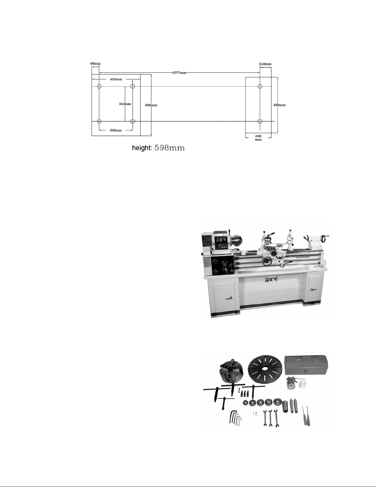
Dimensions of optional stand (p/n 321443AK)
To purchase this optional stand for the BDB-1340A Lathe, contact your dealer or call JET customer
service.
Assembly
Contents of the Shipping Container
(Figures 1 and 2)
1 Lathe
1 Steady Rest (mount ed on lathe)
1 Follow Rest (mounted on lathe)
1 6" Three Jaw Chuck (mount ed on lathe)
1 8" Four Jaw Chuck
1 12" Face Plate (strapped t o c ontainer)
3 Cam Locks
3 Socket Head Cap Scr ews
1 Tool Box (strapped t o c ontainer)
1 Chip Tray
1 Lifting Hook
2 Lifting Blocks
Tool Box:
3 Open End Wrenches (9/ 11, 10/ 12,
12/14mm)
1 Touch-Up Paint
1 Oil Can
1 Hex Socket Wrench Set ( 2.5, 3, 4, 5, 6,
8mm)
2 Shear Pins
1 33T Gear
1 44T Gear
1 46T Gear
1 48T Gear
1 52T Gear
2 T-Handle Chuck Wrenches
1 Tool Post Wrench
2 MT-3 Centers
1 MT-3 to MT-5 Sleeve
1 Cross Point Screwdriver
1 Flat Head Screwdriver
1 Key for Cam Locks
1 Operating Instructions
1 Parts List
1 Warranty Card
Figure 1
(stand not included)
Figure 2

7
Machine is heavy! Use an
appropriate lifting device and use extreme
caution when mo ving the machin e to its final
location. Failure to comply may cause
serious injury.
Uncrating and Clean-Up
1. Finish removing the wooden crate from
around the lathe.
2. Unbolt the lathe from the shipping crate
bottom.
3. Choose a location for the lathe that is dry,
has good light ing, and has enough room t o
be able to service t he lathe on all four sides.
4. Assemble par ts fastened to the crate bottom
used to lift the lathe. See Fig. 3. (Note:
Lifting parts are not tightened in Fig. 3 to
show detail.) Using a piece of leather or a
block of wood under the metal block to
protect the ways during lifting is highly
recommended. Do not lift the lathe by the
spindle. With adequate lifting equipment,
slowly raise the l athe off the shipping crate
bottom. M ake sure lathe is bal anced before
moving to a sturdy bench or optional stand.
5. To avoid twisting the bed, the lathe's
location must be absolutely flat and level.
Bolt the lat he to the stand (if used). If using
a bench, through-bolt for best performance.
6. Clean all rust protected surfaces using a
mild commer cial solvent , kerosene or di esel
fuel. Do not use paint thinner, gasoline, or
lacquer thi nner. These will damage pai nted
surfaces. Cov er all cleaned surf aces with a
ligh t f i lm of Mo b il DTE® Oil Heavy Medium.
7. Remove the end gear cover. Clean all
components of the end gear assembly and
coat all gears with a heavy, non-slinging
grease.
8. Using a machinist’s precision level on the
bedways, check to make sure lathe is level
side to side and front to back. Loosen
mounting bol ts, shim, and tighten mounti ng
bolts, if necessary. The lathe must be level
to be accurate.
Figure 3

8
Chuck Preparation (Three Jaw)
Read and understand all
directions for chuck preparation! Failure to
comply may cause serious injury and/or
damage to the lath e!
Note: Before removing the chuck from the
spindle, pl ace a way board across the bed ways
under the chuck.
1. Support the chuck while turning three
camlocks 1/4 turn counter-clockwise with
the chuck key which is included in the tool
box.
2. Carefully remove t he chuck from the spindl e
and place on an adequate work surface.
3. Inspect the camlock studs. Make sure they
have not become crac ked or broken during
transit. Clean all parts thoroughly with
solvent. Also clean the spindle and
camlocks.
4. Cover all chuck jaws and scroll inside the
chuck with #2 li thium tube grease. Cov er the
spindle, cam locks, and chuck body with a
ligh t f i lm of Mo b il DTE® Oil Heavy Medium.
5. Lift the chuck up to the spindle nose and
press onto the spindle. Tighten in place by
turning the cam locks 1/4 turn clockwise.
The index mark (A, Fig. 4) on the camlock
should be between the t wo indicator ar rows
(B, Fig. 4) when tight. If the index mark is
not between the two arrows, remove the
chuck and adjust the camlock studs by
either turning out one full turn (if cams will
not engage) or turning in one full turn (if
cams turn beyond indic ator marks).
6. Install chuck and tighten in place.
Figure 4
9
Lubrication
Lathe must be serviced at all
lubrication points and all reservoirs filled to
operating level before the lathe is placed into
service. Failure to comply may cause serious
damage to the lath e.
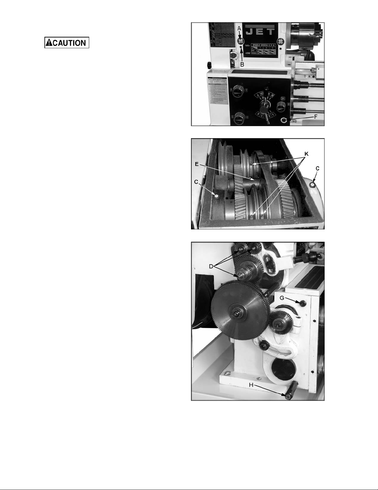
1. Headstock - Oil must be up to indicator
mark in both oil sight glasses (A, Fig. 5).
Top off with Mobil DTE® Oil Heavy Med ium.
The headstock should be drained and
refilled after the first three months of
operation. Then, change oil in the headstock
annually.
Drain oil completely by r em ov ing drain plugs
(B, Fig. 5). Also loosen the t hree set screws
in the pulleys (K, Fig. 6) and shaft ( E , Fig. 6)
and drain the oil fr om these. When done, r e-
tighten the set screws (K,E) and re-insert
the drain plugs (B). Refill by removing fill
plugs (C, Fig. 6). Grease three fittings (D,
Fig. 7) with Mobil 1® Synthetic Universal
Grease daily.
2. External Gears - Coat all gears with a
heavy, non-slinging grease, see Fi gur e 7.
3. Center Back Gear Shaf t - Remove the set
screw on the shaf t (E, Fig. 6) and oi l with a
couple of drops of Mobil DTE® Oil Heavy
Medium once weekly .
4. Quick Chang e Gearbox - Oil m ust be up to
indicator mark in oil sight glass (F, Fig. 5).
Top off with Mobil DTE® O il Heavy Medium.
Fill by removi ng plug (G, Fig. 7). Drain oil by
removing drain plug (H, Fig. 7) and refill
after the first month of operation. Then,
change oil in the gearbox annually.
Figure 5
Figure 6
Figure 7
10
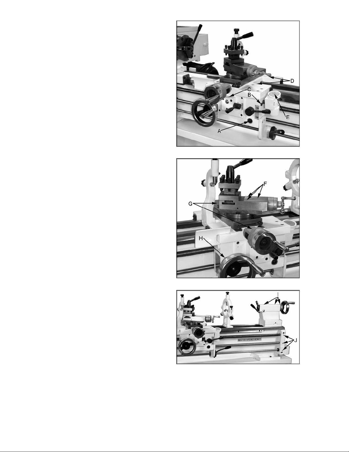
5. Apron - Oil must be up t o indicator mar k in
oil sight glass (A, F ig. 8). Top off with Mobil
DTE® Oil Heavy Medi um. Fill by removing
oil plug (B, Fig. 8). After the first three
months of operation, drain oil completely
(drain is on the bottom of the apron) and
refill with M obil DT E® Oil Heavy Medium, at
a level equival ent t o the indicat or li ne. Then,
change oil annually.
6. Feed Sel ector - Lubric ate ball oiler (C, Fig.
8) once daily with Mobil DTE® Oil Heavy
Medium.
7. Carriage - Lubr icate two ball oi lers (D, Fig.
8) once daily with Mobil DTE® Oil Heavy
Medium.
8. Thread Dial Indicato r - Lubricate ball oiler
(E, Fig. 8) once daily with Mobil DTE® O il
Heavy Medium.
9. Compound Rest - Lubricate three ball
oilers (F , Fig. 9) once daily with M obil DTE®
Oil He avy Me dium.
10. Cross Slide - lubricate four ball oilers (G,
Fig. 9) once daily with Mobil DTE® Oil
Heavy Medium.
11. Longitud inal Feed Handwheel - Lubri cate
ball oiler (H, Fig. 9) once daily with Mobil
DTE® Oil Heavy Me dium.
12. Tailstock - Lubricate thr ee ball oil ers (I , Fig.
10) once daily with Mobil DTE® Oil Heav y
Medium.
13. Leadscrew/F eed Rod - Lubri cate t hree ball
oilers once daily (J, Fig. 10) with Mobil
DTE® Oil Heavy Me dium.
Figure 8
Figure 9
Figure 10

11
Electrical Connections
All electrical connections
must be compl eted by a qualifi ed electrician
and must comply with all relevant codes.
Failure to comply may cause serious injury
and/or damage to the machinery and
property.
The BDB-1340A bench lathe is rated at 2HP,
1PH, 230V only. Confi rm that power available at
the lathe's location is the same rating as the
lathe.
Make sure the lathe is properly grounded.
General Description
Lathe Bed
The lathe bed ( A, Fig. 12) i s made of high grade
cast iron. B y combini ng high cheek s with strong
cross ribs, a bed with low vibration and high
rigidity is realized. Two precision ground vee
slideways, reinforced by heat hardening and
grinding, are an accurate guide for the carriage
and headstock. The main drive motor is
mounted to the rear of the bed.
Carriage
The carriage (B, Fig. 12) is made from high
quality cast i ron. The slidi ng parts are smooth
ground. The cross-slide is mounted on the
carriage and mov es on a dove-tail ed slide whic h
can be adjusted for play by means of the gibs.
The compound slide (C, Fig. 12), which is
mounted on the c ross slide (D, Fi g. 12), can be
rotated through 360°. The compound slide and
the cross slide travel in a dovetail slide and hav e
adjustable gi bs. A f our-way tool post (E , Fig. 12)
is fitted on the com pound sli de.
Headstock
The headstock (F, Fig. 12) is cast from high
grade, low vibration cast iron. It is mounted to
the bed by four bolt s with two adjusting bol ts for
alignment. In the head, the spindle is mounted
on two precision taper roller bearings. The
hollow spindle has Morse Taper #5 wit h a 1-3/ 8"
bore.
Four Way Tool Post
The four-way tool (E, Fig. 12) post is mounted
on the compound slide and allows a maximum
of four tools to be mounted simultaneously.
Remember to use a mi nimum of two clamping
screws when installing a cutting tool.
Figure 11
Figure 12

12
Apron
The apron (A, Fig. 13) is mounted to the
carriage. In the apron a hal f nut is fitted. The
half nut gi bs can be adjusted from t he outside.
The half nut is engaged by us e of a l ever. Quic k
travel of the apr on is accom pl i shed by m eans of
a bed-mounted rack and pinion, operated by a
hand wheel on the front of t he apr on.
Tailstock
The tailstoc k (B, Fig. 13) slides on a v- way and
can be locked at any location by a clamping
lever. The tailstock has a heavy-duty spindle
with a Morse Taper #3.
Leadscrew and Feed Rod
The leadscre w (C Fig. 13) and f eed rod ( D, Fi g.
10) are mounted on the front of the machine
bed. They are connec ted to the gearbox at the
left for automatic feed and lead. They are
supported by bushings on both ends. Both are
equipped with brass shear pins.
Gear Box
The gear box (E, Fig. 13) is made from high
quality cast i ron and is mounted to t he left side
of the machine bed.
Steady Rest
The steady rest (F, Fig. 13) serv es as a support
for shaft s on the free tailstoc k end. The steady
rest is mounted on the bedway and secured
from below with a bolt, nut and locking plate.
The sliding fingers require c ontinuous lubri c ation
at the contact points with the workpiece to
prevent pr em ature wear.
Follow Rest
The traveli ng follow rest (G , Fig. 13) is mounted
on the saddle and f ollows the movement of the
turning tool . Only two finger s are requi red as the
turning tool takes the place of the third. The
follow rest is used for turning operati ons on l ong,
slender workpieces. It prevents flexing of the
workpiece f r om the pr essure of t he cutting tool.
The slidi ng fingers are set simi lar to the steady
rest, free of play, but not binding. The sliding
fingers require continuous lubrication at the
contact points with the workpiece to prevent
prematur e wear.
Figure 13
13
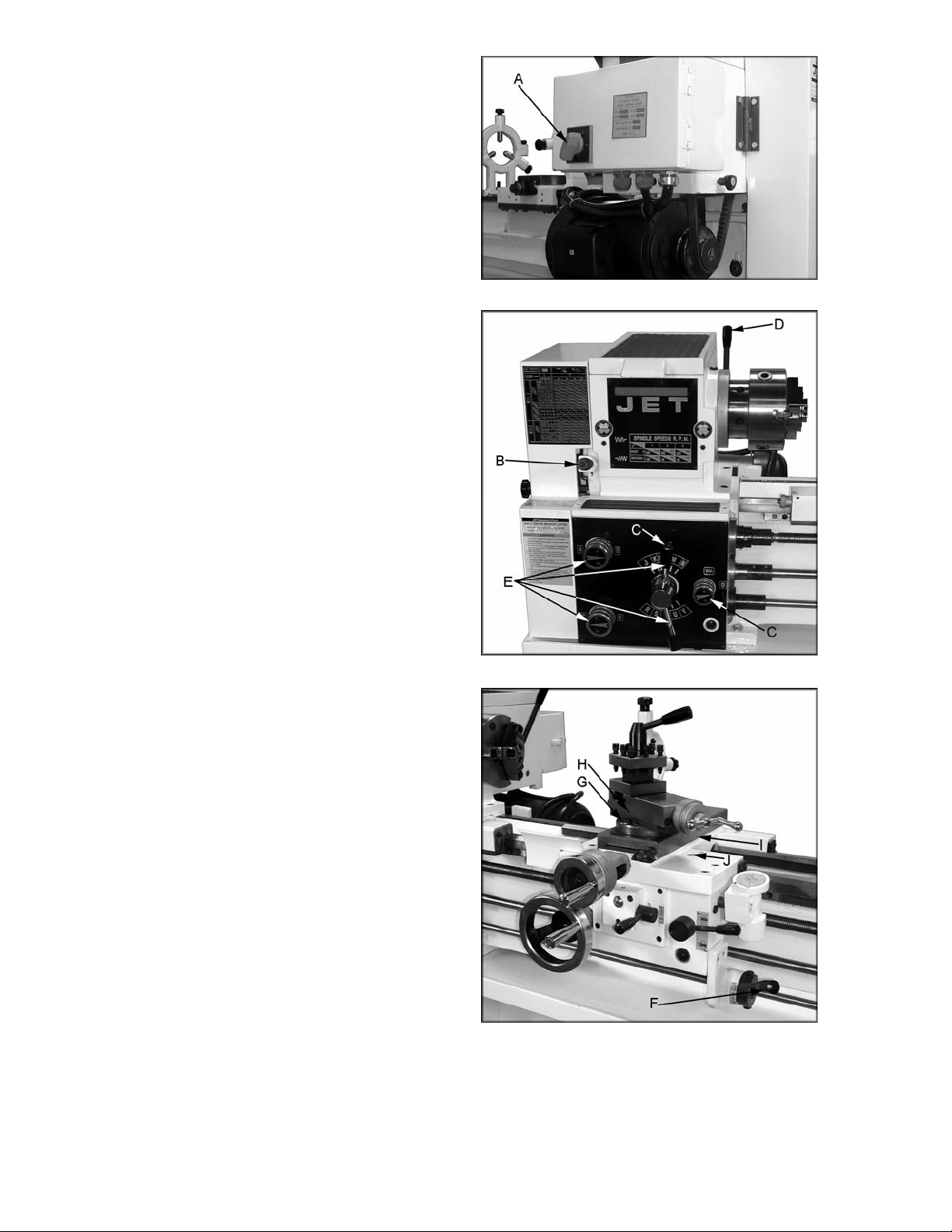
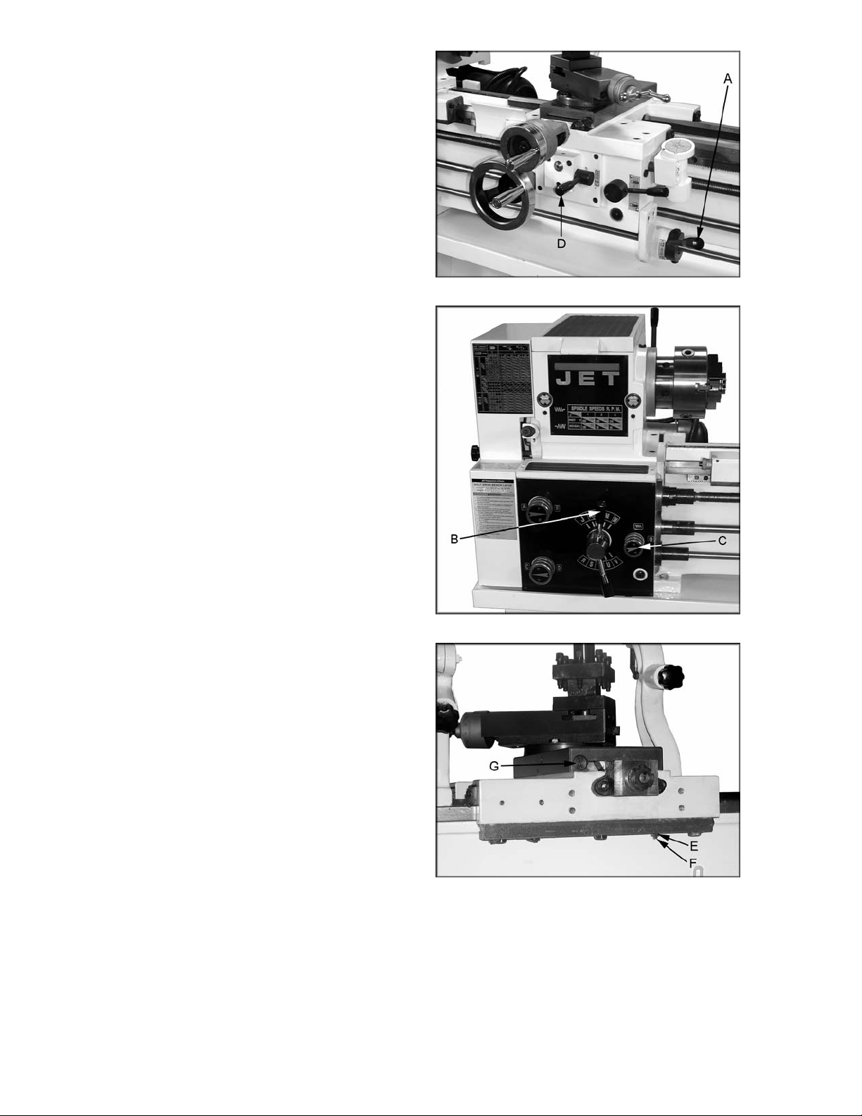
Controls
1. Main On-Off Switch (A, Fig. 14) – Power i s
off in the “0” position and on in the “I”
position.
2. Feed Direction Selector (B, Fig. 15) –
Arrows above the handle indicate saddle
travel dir ection when the chuck is rot ating in
the forward direction or counter-clockwise
as viewed from the front of the chuck.
3. Feed Rod/ Leadscrew Select or (C, Fi g. 15)
– Use knob and lever to activat e leadscrew
and feed rod.
4. Belt Tensioning Handle (D, Fig. 15) – Pull
forward to rel ease tension on the driv e belt.
Push toward the rear t o tension the belt.
5. Feed Rate Selector (E, Fig. 15) – Two
knobs and two handl es used to set desired
feed, or lead rat es.
6. Forw ard/Reverse Lever ( F, Fi g. 16) – Pull
lever up for clockwise spindle rotation
(reverse). Push lever down for counter-
clockwise spindl e rotation (f orward). Neutral
position is a center detent and the spindle
remains idle.
7. Compound Rest Lock (G, Fig. 16) – Turn
hex nut clockwise to lock and counter-
clockwise to unlock.
8. Compound Slide Lock (H, Fig. 16) – Turn
set screw cloc kwise to tighten and counter -
clockwise to loosen.
9. Cross Slide Lock (I, Fig. 16) – Turn set
screw clockwise, and tighten to lock. Turn
counter-clockwise and loosen to unlock.
Caution: cross slide lock screw must be
unlocked before engaging automatic feeds
or damage to the lathe may occur.
10. Carriage Lock (J, Fig. 16) – Turn hex
socket cap screw clockwise and tighten to
lock. Turn counter-clockwise and loosen to
unlock. Caution: Carriage lock screw must
be unlocked before engaging automatic
feeds or damage to lathe may occur.
Figure 14
Figure 15
Figure 16
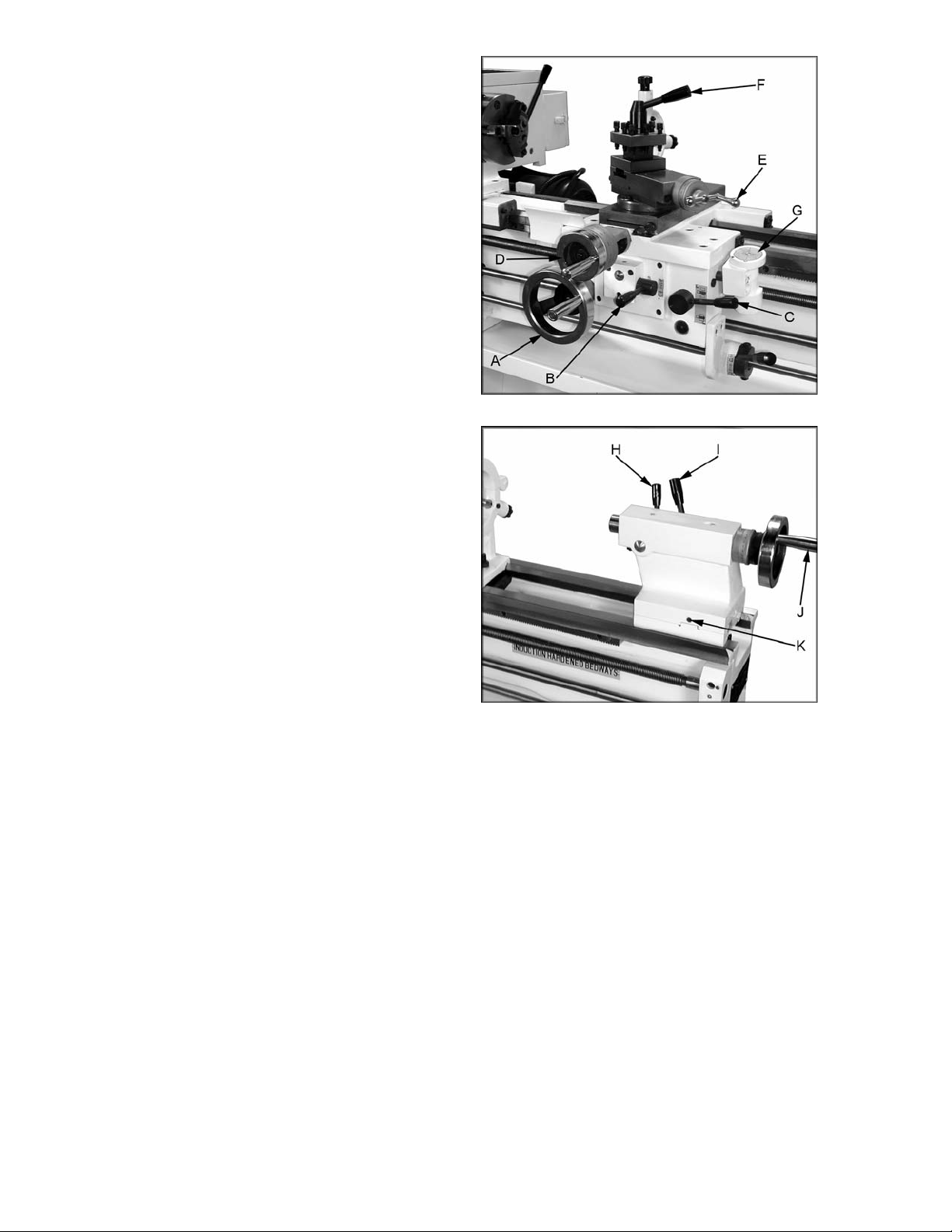
14
11. Longitud inal T raverse Hand wheel (A, Fig.
17) – Rotate handwheel cl ockwise to move
the apron assembly toward the tailstock
(right). Rotate the wheel counter-clockwise
to move the apron assembly toward the
headstock (left).
12. Feed Sel ector (B, Fig. 17) – Push l ever to
the left and down to activate the crossfeed
function. Pull lever to the right and up to
activate the longitudinal function.
13. Half Nut Engag e Lever (thread cutting) (C,
Fig. 17) – Move the l ever down to engage.
Move the lever up to disengage.
14. Cross T raverse Handwheel (D, Fig. 17) –
Clockwise rotation moves the cross slide
toward the rear of t he machine.
15. Compound Rest Traverse Handwheel (E,
Fig. 17) – Rotate clockwise or counter-
clockwise to mov e or positi on.
16. Tool Post Clamping Lever (F, Fig. 17) –
Rotate counter-clockwise to loosen and
clockwise to tighten. Rotate the tool post
when the lever is unl oc k ed.
17. Threading Dial (G, Fig. 17) – Engage by
pushing into the leadscrew. Pull out to
disengage. The di al indicator and chart will
specify at which point a thread can be
entered.
18. Tailstock Quill Clamping Lever (H, Fig.
18) – Lift up to lock t he spindle. Push down
to unlock.
19. Tailsto ck Clamping Lever (I, Fi g. 18) – Lift
up lever to lock. Push down lev er to unloc k.
20. Tailstock Quill Traverse Handwheel (J,
Fig. 18) – Rotat e clockwise to adv ance the
quill. Rot ate count er-clockwise to ret ract t he
quill.
21. Tailstock Off-Set Adjustment (K, Fig. 18)
– Three set screws located on t he tailstock
base are used to off-set the tailstock for
cutting tapers. Loosen lock screw on
tailstock end. Loosen one side s et scre w (K,
Fig. 18) while tightening the other until the
amount of off-set is indicated on scale.
Tighten lock screw.
Figure 17
Figure 18
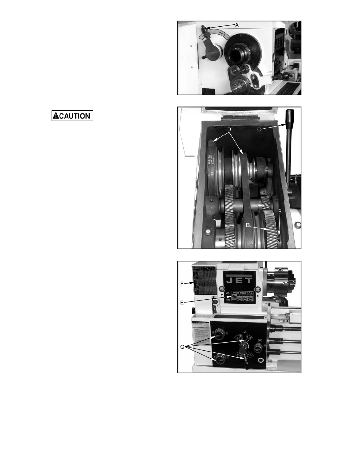
15
22. High-Low Speed Selector (A, Fig. 19) -
Push toward the re ar of t he machine f or the
high-speed range and pull toward the front
for the low speed range.
23. Lock Pin fo r Back Gear (B, Fig. 20) – For
high-speed operation, pull out pin and turn
pin 90° clockwise to engage back gear (B
1
).
To disengage the back gear for low-speed
operation, pul l t he pin out, turn 90° count er-
clockwise, and rot ate the chuc k until the pi n
seats.
Engage back gear only
for high -speed operation . Do not operate
in low-speed range while back gear (B
1
)
is engaged. Failure to comply may result
in gear damage.
Adjustments
Break-In Procedure
During manuf acturing and testi ng, thi s lathe has
been operated in the l ow R.P.M. range for t hree
hours.
To allow time for the gears and bearings to
break-in and run sm oothly, do not run the lathe
above 580 R.P.M. for the first six hours of
operation and use.
Speed Selection
To change speeds, disconnect the lathe from
the power source and remove the tension by
pulling handle (C, Fig. 20) forward. Move the
belts (D, Fig. 20) to the desired location
according to the speed selection chart (E, Fig.
21). Tension the belts by moving the handle
towards the rear.
Feed and Thread Selection
1. Reference the feed and thread tables (F,
Fig. 21).
2. Move levers and knobs (G, Fig. 21) to the
appropriate posi tion.
Figure 19
Figure 20
Figure 21
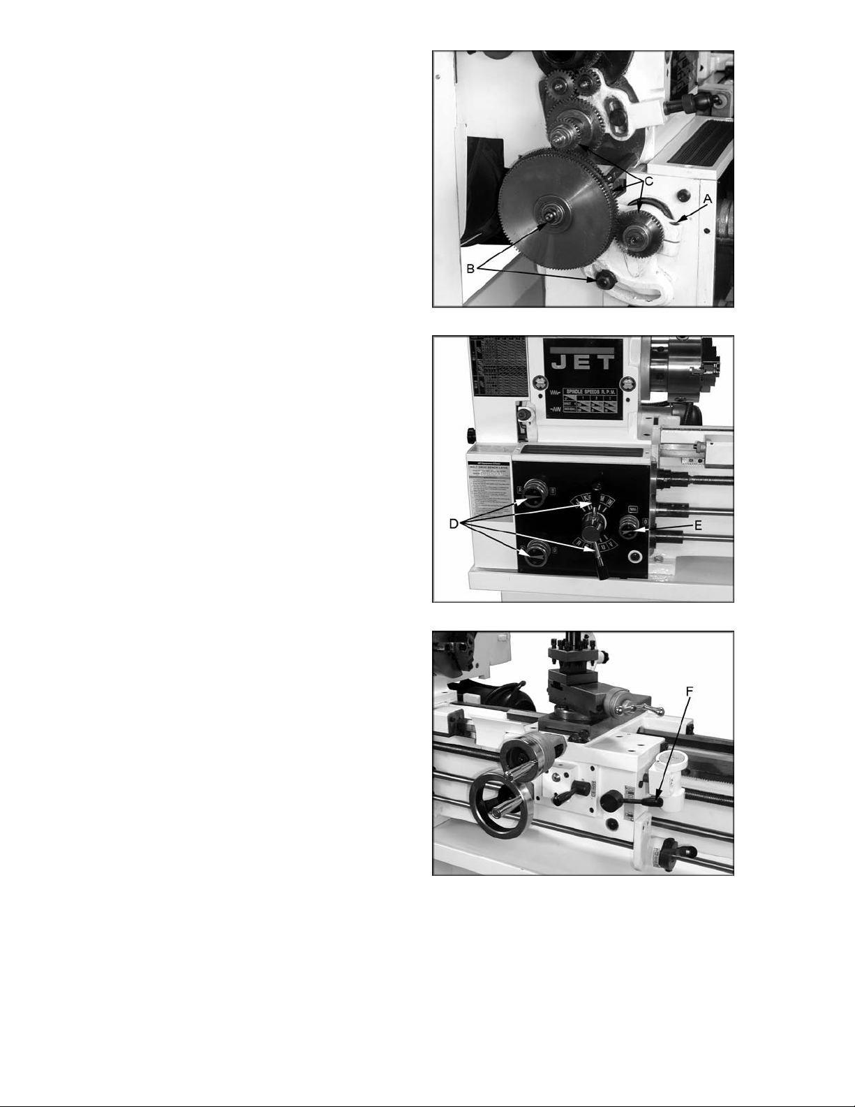
16
Change Gear Replacement
Note: The 32T x 127T x 48T gears are i nstall ed
in the end gear compartment when delivered
from the factory. This combination will cover
most inch feeds and threads under normal
circumstanc es. The additional gears found in the
toolbox are used for some metric threads and
feeds.
1. Disconnect the machine from the power
source.
2. Open the end cover on the left end of the
headstock.
3. Loosen t he socket head cap screw (A, Fi g.
22) and hex nuts (B, Fig. 22). Move the
quadrant out of the way.
4. Change gears (C, Fig. 22) t o match t he feed
and thread chart.
5. Thoroughly cl ean and install new gears.
6. Move the quadrant so the large gear
meshes with the smaller gears and tighten
to secure in pl ace. Note: Make sure t here is
backlash of 0.002” – 0.003” between gears.
Setting the gears too tight will cause
excessiv e noise and wear.
7. Close the cover and connec t t he machine t o
the power source.
Thread Cutting
1. Set feed rate selectors (D, Fig. 23) i n proper
position for the correct feed rate of the
thread to be cut.
2. Mov e knob (E, Fi g. 23) to the “0” posi tion to
disengage the feed rod.
3. Engage the half nut lev er (F, Fi g. 24).
4. The half nut lever and threading dial are
used to thread in t he conventi onal manner.
The thread dial chart specifies at which
point a thread can be entered using the
threading di al .
5. To c ut metri c threads, the half nuts m ust be
left continuall y engaged once the start point
has been selec ted and the half nut is initiall y
engaged (thread dial cannot be used).
Figure 22
Figure 23
Figure 24

17
Thread and Feed Chart
18
Automatic Feed Operation and Feed
Changes
1. Move forward/reverse selector (A, Fig. 25)
up or down depending on desired direction.
2. Set the selector handle (B, Fig. 26) to the
“P” position and turn knob (C, Fig. 26)
counter-clockwise so the arrow is pointing
up to start the feed rod r otati ng.
Powered Carriage Travel
Push lev er (D, Fig. 25) to the l eft and down to
engage crossfeed. Pull lever to the right and up
to engage longitudinal feed.
Saddle Adjustment
1. Loosen f our hex nuts (E, Fig. 27) found on
the bottom rear of the c r oss slide.
2. Turn each of the four set screws (F, Fi g. 27)
equally with a hex wrench until a slight
resistance is felt. Do not over tighten.
3. Move the carriage wit h the hand wheel and
determine if drag is to y our preference. Re-
adjust the setscrews as necessary to
achieve the desi r ed dr ag.
4. Hold socket set screw firmly with a hex
wrench and tighten hex nut to lock in place.
5. Move the carriage again and adjust if
necessary. Note: Over adjustment will
cause excessive premature wear of the
gibs.
Cross Slide Adjustment
If the cr oss slide i s too loose, f ollow procedure
below to tighten:
1. Loosen the rear gib screw (G, Fig. 27)
approxim ately one turn.
2. Ti ghten front gib screw a quarter tur n. Turn
the cross slide handwheel to see if the cr oss
slide is still loose. If it is still loose, tighten
the front screw a bit mor e and try again.
3. When cross slide i s properly adjusted, snug
rear gib screw. Do not ov er tighten. This
will cause premature wear on the gib and
mating parts.
Figure 25
Figure 26
Figure 27

19
Compound Rest Adjustment
Follow the same proc edur e as for the cross slide
adjustment.
Tailstock Adjustment
If the handle will not lock the tailstock securely,
use the following procedur e:
1. Lower handle to the unl oc k ed posi tion.
2. Slide tail stock to an area that will allow you
to reach under the tailstock.
3. Tighten t ailstock clamping nut 1/4 t urn, and
re-test for proper locking. Repeat as
necessary.
Half Nut Gib Adjustment
1. Remove the thread dial assembly by
unscrewing the scre w (A, Fig. 28).
2. Loosen t hree hex nut s (B, Fig. 28) f ound on
the side of apr on, and turn t hree set scre ws
(C, Fig.28) equal ly with a hex wrench.
3. Adjust properly for wear and play. Hold
socket set screw firmly with a hex wrench
and tighten hex nut to lock in place. Note:
Over adjustment will cause excessive
prematur e wear on gib and mati ng par ts.
Headstock Alignment
The headstock has been aligned at the factory
and should not require adjustment. However , if
adjustment is deemed necessary, follow the
procedure below to al ign the headstock.
1. Using an engineer's precision level on the
bedways, make sure the lathe is level side
to side and f ront to back. If the lathe i s not
level, correct to a level condition before
proceeding. Re- test alignment if any leveli ng
adjustments were made.
2. From steel bar stock of approximately two
inches in diameter, cut a piece
approximately eight inches long.
3. Place two inc hes of bar stock into c huc k and
tighten chuck. Do not use the tailstock or
center to support the other end.
4. Set up and cut along fiv e inches of the bar
stock.
Figure 28

20
5. Using a microm eter, measure the bar stock
next to the chuck and at the end. The
measurement should be the same.
6. If the measurements are not the same and
adjustment is required, loosen the f our bolt s
that hold the headstock to the bed. Do not
loosen completely; some drag should
remain.
7. Loosen two hex nuts found on the two
adjusting bolts located on the backside of
headstock just above the motor mount
bracket. A djust the bolts for ali gnment and
tighten hex nuts. Tighten the headstock
bolts and mak e another c ut. Keep adj usti ng
screws after each cut until the bar stock
measurements are the same. Tighten all
headstock bolts and jam nuts on adjusting
screws.
Removing Gap Bridge
1. Using an open end wrench, tighten the t wo
hex nuts (A, Fig. 29). This will cause the
taper pins (B, Fig. 29) to rel ease. Remove
the taper pins.
2. Rem ove the four hex socket cap screws (C,
Fig. 29) with a hex key wrench.
3. Gap bridge can now be removed.
Installing Gap Bridge
1. Clean the bottom and the ends of the gap
bridge thoroughly.
2. Set gap bridge in plac e and align.
3. Remove nuts (A, Fig. 29) from the taper
pins (B, Fig. 29).
4. Slide taper pins in their r espective holes and
seat using a m allet. Install nuts on the taper
pins finger tight.
5. Install four socket head cap screws (C, Fi g.
29) and tighten secur ely.
Figure 29
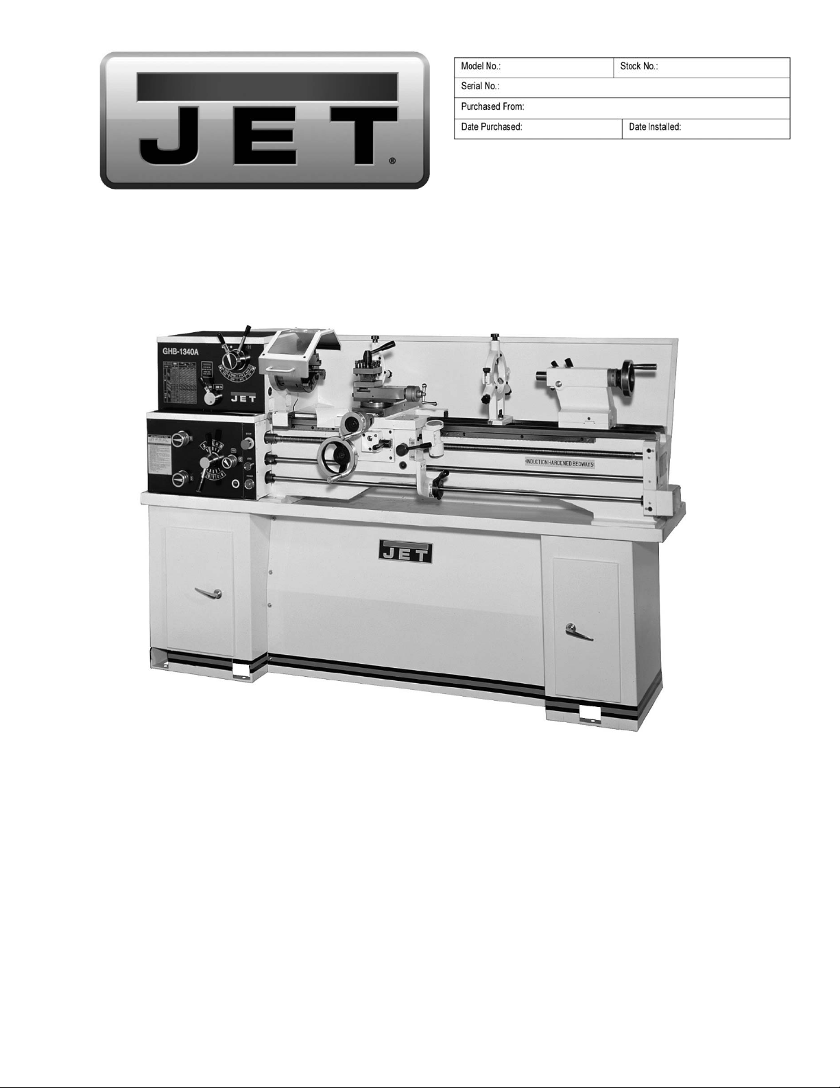
Parts List and Electrical Diagrams
For Lathe models BDB-1340A, GHB-1340 A, GHB-1440A
(GHB-1340A shown with opt ional stand 321443AK)
For GHB-1340A/1440A Operat ing Instructions, see document M-321357A-1
For BDB-1340A Operatin g Inst ructions, see document M - 321360A
JET
427 New Sanford Road
LaVergne, Tennessee 37086 Part No. M-321357A
Ph.: 800-274-6848 Revision
I 11/2014
www.jettools.com Copyright © 2014 JET
This .pdf document is bookmarked
 Loading...