


 Loading...
Operating Instructions and Parts Manual
20-inch Drill Press
Model: JDP-20MF
JET |
|
427 New Sanford Road |
Part No. M-354170 |
LaVergne, Tennessee 37086 |
|
Ph.: 800-274-6848 |
Revision J2 09/2018 |
www.jettools.com |
Copyright © 2017 JET |

1.Read and understand the entire owner’s manual before attempting assembly or operation.
2.Read and understand the warnings posted on the machine and in this manual. Failure to comply with all of these warnings may cause serious injury.
3.Replace the warning labels if they become obscured or removed.
4.This drill press is designed and intended for use by properly trained and experienced personnel only. If you are not familiar with the proper and safe operation of a drill press, do not use until proper training and knowledge have been obtained.
5.Do not use this drill press for other than its intended use. If used for other purposes, JET disclaims any real or implied warranty and holds itself harmless from any injury that may result from that use.
6.Always wear approved safety glasses/face shields while using this drill press. Everyday eyeglasses only have impact resistant lenses; they are not safety glasses.
7.Before operating this drill press, remove tie, rings, watches and other jewelry, and roll sleeves up past the elbows. Remove all loose clothing and confine long hair. Non-slip footwear or anti-skid floor strips are recommended. Do not wear gloves.
8.Wear ear protectors (plugs or muffs) during extended periods of operation.
9.Do not operate this machine while tired or under the influence of drugs, alcohol or any medication.
10.Make certain the switch is in the OFF position before connecting the machine to the power supply.
11.Make certain the machine is properly grounded.
12.Make all machine adjustments or maintenance with the machine unplugged from the power source.
13.Remove adjusting keys and wrenches. Form a habit of checking to see that keys and adjusting wrenches are removed from the machine before turning it on.
14.Keep safety guards in place at all times when the machine is in use. If removed for maintenance purposes, use extreme caution and replace the guards immediately.
15.Make sure the drill press is firmly secured to the floor or bench before use.
16.Check damaged parts. Before further use of the machine, a guard or other part that is damaged should be carefully checked to determine that it will operate properly and perform its intended function. Check for alignment of moving parts, binding of moving parts, breakage of parts, mounting and any other conditions that may affect its operation. A guard or other part that is damaged should be properly repaired or replaced.
17.Provide for adequate space surrounding work area and non-glare, overhead lighting.
18.Keep the floor around the machine clean and free of scrap material, oil and grease.
19.Keep visitors a safe distance from the work area. Keep children away.
20.Make your workshop child proof with padlocks, master switches or by removing starter keys.
21.Give your work undivided attention. Looking around, carrying on a conversation and “horse-play” are careless acts that can result in serious injury.
22.Maintain a balanced stance at all times so that you do not fall or lean against the spindle or other moving parts. Do not overreach or use excessive force to perform any machine operation.
23.Use the right tool at the correct speed and feed rate. Do not force a tool or attachment to do a job for which it was not designed. The right tool will do the job better and more safely.
24.Use recommended accessories; improper accessories may be hazardous.
25.Maintain tools with care. Keep drill bits sharp and clean for the best and safest performance. Follow instructions for lubricating and changing accessories.
2

26.Make sure the work piece is securely attached or clamped to the table. Never use your hand to hold the work piece.
27.Turn off the machine before cleaning. Use a brush or compressed air to remove chips or debris — do not use your hands.
28.Do not stand on the machine. Serious injury could occur if the machine tips over.
29.Never leave the machine running unattended. Turn the power off and do not leave the machine until it comes to a complete stop.
30.Remove loose items and unnecessary work pieces from the area before starting the machine.
 WARNING: This product can expose you to chemicals including lead which is known to the State of California to cause cancer and birth defects or other reproductive harm. For more information go to http://www.p65warnings.ca.gov.
WARNING: Some dust, fumes and gases created by power sanding, sawing, grinding, drilling, welding and other construction activities contain chemicals known to the State of California to cause cancer and birth defects or other reproductive harm. Some examples of these chemicals are:
•lead from lead based paint
•crystalline silica from bricks, cement and other masonry products
•arsenic and chromium from chemically treated lumber
Your risk of exposure varies, depending on how often you do this type of work. To reduce your exposure to these chemicals, work in a well-ventilated area and work with approved safety equipment, such as dust masks that are specifically designed to filter out microscopic particles. For more information go to http://www.p65warnings.ca.gov/ and http://www.p65warnings.ca.gov/ wood.
Familiarize yourself with the following safety notices used in this manual:
 This means that if precautions are not heeded, it may result in minor injury and/or possible machine damage.
 This means that if precautions are not heeded, it may result in serious injury or possibly even death.
- - SAVE THESE INSTRUCTIONS - -
3
Table of Contents |
|
Warnings ....................................................................................................................................................... |
2 |
Specifications ................................................................................................................................................ |
5 |
Shipping Contents......................................................................................................................................... |
6 |
Required Tools (not included)....................................................................................................................... |
6 |
Assembly....................................................................................................................................................... |
7 |
Before Assembly ....................................................................................................................................... |
7 |
Column to Base ......................................................................................................................................... |
7 |
Table Bracket and Rack ............................................................................................................................ |
7 |
Crank Handle............................................................................................................................................. |
8 |
Column Lock Handle ................................................................................................................................. |
8 |
Table Installation ....................................................................................................................................... |
8 |
Head Assembly ......................................................................................................................................... |
9 |
Chuck and Arbor Installation ..................................................................................................................... |
9 |
Chuck and Arbor Removal ........................................................................................................................ |
9 |
Chuck Guard ........................................................................................................................................... |
10 |
Adjustment .................................................................................................................................................. |
10 |
Depth Stop Adjustment............................................................................................................................ |
10 |
Changing Spindle Speeds....................................................................................................................... |
10 |
Return Spring Adjustment ....................................................................................................................... |
11 |
Work Light ............................................................................................................................................... |
11 |
Table Tilt Adjustment............................................................................................................................... |
11 |
Operation..................................................................................................................................................... |
12 |
Installing Drills ......................................................................................................................................... |
12 |
Positioning the Workpiece....................................................................................................................... |
12 |
Using the Vise ......................................................................................................................................... |
12 |
Basic Operation ....................................................................................................................................... |
12 |
Maintenance................................................................................................................................................ |
12 |
Lubrication................................................................................................................................................... |
12 |
Electrical...................................................................................................................................................... |
12 |
115 Volt Operation................................................................................................................................... |
12 |
230 Volt Operation................................................................................................................................... |
13 |
Grounding Instructions ............................................................................................................................ |
13 |
Extension Cords ...................................................................................................................................... |
13 |
Troubleshooting JDP-20MF Drill Press....................................................................................................... |
14 |
Replacement Parts...................................................................................................................................... |
15 |
Exploded View Drawing JDP-20MF ........................................................................................................ |
16 |
Parts List JDP-20MF ............................................................................................................................... |
17 |
Wiring Diagram ........................................................................................................................................... |
20 |
JDP-20MF Electrical Schematic – 115V ................................................................................................. |
20 |
JDP-20MF Electrical Schematic – 230V ................................................................................................. |
20 |
The specifications in this manual are given as general information and are not binding. JET reserves the right to effect, at any time and without prior notice, changes or alterations to parts, fittings, and accessory equipment deemed necessary for any reason whatsoever.
4
Specifications
Model Number................................................................................................................................ |
JDP-20MF |
Stock Number ..................................................................................................................................... |
354170 |
Type ........................................................................................................................................................ |
Floor |
Motor: |
|
Horsepower ...................................................................................................................................... |
1-1/2 |
Phase............................................................................................................................................... |
single |
Voltage............................................................................................................ |
115/230V (prewired 115V) |
Frequency........................................................................................................................................ |
60 Hz |
FLA (Full Load Amperage) ............................................................................................................. |
18/9 A |
Capacities: |
|
Drills to Center Circle........................................................................................................................... |
20” |
Distance Column to Spindle ................................................................................................................ |
10” |
Drilling Capacity – Cast Iron .................................................................................................................. |
1” |
Drilling Capacity – Mild Steel.............................................................................................................. |
3/4" |
Chuck Size.......................................................................................................................................... |
3/4” |
Speeds: |
|
Number of Spindle Speeds................................................................................................................... |
12 |
Range of Spindle Speeds (RPM) ........................................................................................... |
150 – 4200 |
Spindle: |
|
Spindle Taper ................................................................................................................................... |
MT-3 |
Spindle Travel.................................................................................................................................. |
4-5/8” |
Spindle Distance to Base .............................................................................................................. |
46-3/4” |
Spindle Distance to Table (max.) .................................................................................................. |
29-1/8” |
Table and Column: |
|
Table Size (Length x Width) ................................................................................................ |
18-1/2" x 16" |
Table Weight Capacity ..................................................................................................................... |
80 lb |
Table T-Slots, Number ........................................................................................................................... |
6 |
Table T-Slots, Size ............................................................................................................................. |
1/2" |
Table T-Slots, Centers..................................................................................................................... |
3-1/2” |
Table Tilt ....................................................................................................................................... |
45 deg. |
Column Diameter............................................................................................................................. |
3-3/8” |
Base: |
|
Base Size....................................................................................................................... |
13-3/4” x 22-3/4” |
Base Working Surface............................................................................................................ |
13” x 8-1/2” |
Base Slots, Number................................................................................................................................ |
2 |
Base Slots, Size.................................................................................................................................. |
5/8” |
Dimensions: |
|
Overall Dimensions (H x W x D)........................................................................... |
66" x 18-1/2" x 31-1/2" |
Carton Size (L x W x H):.................................................................................................... |
26" x 13" x 58" |
Weights: |
|
Net Weight (approx.) ................................................................................................................... |
282 lbs. |
Gross Weight .............................................................................................................................. |
293 lbs. |
5
Shipping Contents
Unpack the carton and verify that all parts listed below are included.
Main Parts
1 ea |
Head Assembly |
1 ea |
Table |
1 set |
Column and Table Bracket Assembly |
1 ea |
Base |
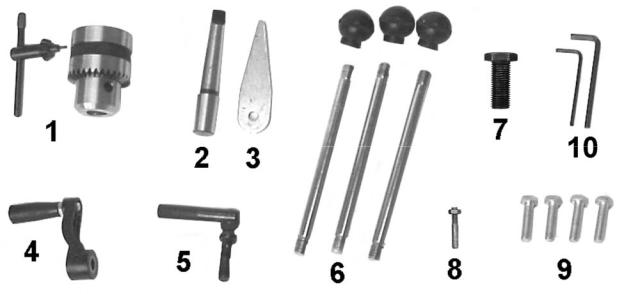
Additional Parts
1. |
1 set |
Chuck and Chuck Key |
2. |
1 pc |
Arbor |
3. |
1 pc |
Drift Key |
4. |
1 pc |
Table Crank Handle |
5. |
1 pc |
Column Lock Handle |
6. |
3 pcs |
Downfeed Handles and Knobs |
7. |
1 pc |
5/8"-11x2" Hex Cap Screw |
8. |
1 set |
Locator Pin and Hex Nut |
9. |
4 pcs |
M10 x 40 Hex Cap Screws |
10. |
2 pc |
Hex Wrenches (3mm, 5mm) |
11. |
1 pc |
Chuck Guard (not shown) |
Other Material
1 ea |
Owner’s Manual |
1 ea |
Product Registration Card |
Required Tools (not included)
1.17mm Box Wrench or a 6” – 8” Adjustable Wrench
2.15/16" wrench
Additional Parts
6

Assembly
 Read and understand all assembly instructions before attempting assembly! Failure to comply may cause serious injury!
 Do not attempt to turn on power before this machine is completely assembled.
Before Assembly
1.Remove contents from shipping container.
2.Compare contents of shipping container with the list on page 6. Report any shortages or damage to your JET distributor.
3.Clean all rust protected surfaces with kerosene or a light solvent. Do not use lacquer thinner, paint thinner, or gasoline. These will damage plastic components and painted surfaces.
Column to Base
Referring to Figure 1:
1.Place the base (A) on a level floor.
2.Place the column assembly (B) on the base
(A) and align the holes in the column support with the holes in the base.
3.Using a 19mm wrench, secure the column (B) with four M10 x 40 hex cap screws (C) to the base.
Table Bracket and Rack
Referring to Figures 2 and 3:
When shipped, the rack ring and rack are bundled together with the column in plastic wrap.
1.Remove the wrap and take the rack ring (D) and rack (E) off the column (B).
2.Insert worm gear shaft (G) through hole of bracket (F) and mesh with worm (H).
3.Position rack (E) in U-slot of bracket with arrow pointing upward, and slide this assembly together onto the column.
4.Slide rack ring (D) over column (B), placing it so it rests against rack (E) as shown in Figure 3. Tighten firmly with 3mm hex wrench (provided).
Figure 1
Figure 2
Figure 3
7

Crank Handle
Referring to Figure 4:
1.Loosen the setscrew (B) on the table crank handle (A).
2.Slide the handle (A) onto the table bracket shaft.
3.Turn the handle until the setscrew is opposite the flat section on the shaft, and tighten the setscrew to secure the handle.
Column Lock Handle
Referring to Figure 5:
Thread the column lock handle (A) into the table bracket (B).
Table Installation
 The table is heavy! This installation is a two person operation to avoid injury from accidental dropping.
Referring to Figure 6:
1.Have one person hold the table (A) against the bracket (B), aligning the hole in the mounting plate of the table with the threaded hole in bracket.
2.Have the second person insert the 5/8"-11x2 hex head screw (C) through the opening on the bottom side of the table (A) and start threading the screw into the bracket by hand.
3.Finish tightening the screw (C) with a 15/16" or wrench (wrench provided), but leave loose enough so the table can be tilted by hand.
4.Using the scale on the bracket as a guide, set the table angle to 0 degrees (level).
5.Take the locator pin (D) and adjust the hex nut towards the end of the thread as shown in the close up view (D).
6.Insert the non-threaded end of the locator pin
(D)into the hole on the table found just below the mounting screw. Press all the way in.
Note: The table may have to be tilted slightly back and forth if the holes do not quite align.
7. Tighten the screw (C) with a 15/16" wrench.
Figure 4
Figure 5
Figure 6
8
Loading...