


 Loading...
Operating Instructions and Parts Manual
Disc, Belt and Combination Disc/Belt Sanders
Models: J-4200A |
J-4300A |
J-4400A |
J-4200A-2 |
J-4301A |
J-4401A |
J-4202A |
|
|
J-4200A Disc/Belt Sander |
J-4300A Belt Sander |
J-4400A Disc Sander |
JET |
|
427 New Sanford Road |
Part No. M-414551 |
LaVergne, Tennessee 37086 |
|
Ph.: 800-274-6848 |
Revision C1 01/2014 |
www.jettools.com |
Copyright © 2014 JET |

1.0 Warranty and Service
JET, Wilton and Powermatic warrants every product they sell against manufacturers’ defects. If one of our tools needs service or repair, please contact Technical Service by calling 1-800-274-6846, 8AM to 5PM CST, Monday through Friday
Warranty Period
The general warranty lasts for the time period specified in the literature included with your product or on the official JET, Wilton or Powermatic branded websites.
•JET, Wilton and Powermatic products carry a limited warranty which varies in duration based upon the product. (See chart below)
•Accessories carry a limited warranty of one year from the date of receipt.
•Consumable items are defined as expendable parts or accessories expected to become inoperable within a reasonable amount of use and are covered by a 90 day limited warranty against manufacturer’s defects.
Who is Covered
This warranty covers only the initial purchaser of the product from the date of delivery.
What is Covered
This warranty covers any defects in workmanship or materials subject to the limitations stated below. This warranty does not cover failures due directly or indirectly to misuse, abuse, negligence or accidents, normal wear-and-tear, improper repair, alterations or lack of maintenance.
Warranty Limitations
Woodworking products with a Five Year Warranty that are used for commercial or industrial purposes default to a Two Year Warranty. Please contact Technical Service at 1-800-274-6846 for further clarification.
How to Get Technical Support
Please contact Technical Service by calling 1-800-274-6846. Please note that you will be asked to provide proof of initial purchase when calling. If a product requires further inspection, the Technical Service representative will explain and assist with any additional action needed. JET, Wilton and Powermatic have Authorized Service Centers located throughout the United States. For the name of an Authorized Service Center in your area call 1-800-274-6846 or use the Service Center Locator on the JET, Wilton or Powermatic website.
More Information
JET, Wilton and Powermatic are consistently adding new products. For complete, up-to-date product information, check with your local distributor or visit the JET, Wilton or Powermatic website.
How State Law Applies
This warranty gives you specific legal rights, subject to applicable state law.
Limitations on This Warranty
JET, WILTON AND POWERMATIC LIMIT ALL IMPLIED WARRANTIES TO THE PERIOD OF THE LIMITED WARRANTY FOR EACH PRODUCT. EXCEPT AS STATED HEREIN, ANY IMPLIED WARRANTIES OF MERCHANTABILITY AND FITNESS FOR A PARTICULAR PURPOSE ARE EXCLUDED. SOME STATES DO NOT ALLOW LIMITATIONS ON HOW LONG AN IMPLIED WARRANTY LASTS, SO THE ABOVE LIMITATION MAY NOT APPLY TO YOU.
JET, WILTON AND POWERMATIC SHALL IN NO EVENT BE LIABLE FOR DEATH, INJURIES TO PERSONS OR PROPERTY, OR FOR INCIDENTAL, CONTINGENT, SPECIAL, OR CONSEQUENTIAL DAMAGES ARISING FROM THE USE OF OUR PRODUCTS. SOME STATES DO NOT ALLOW THE EXCLUSION OR LIMITATION OF INCIDENTAL OR CONSEQUENTIAL DAMAGES, SO THE ABOVE LIMITATION OR EXCLUSION MAY NOT APPLY TO YOU.
JET, Wilton and Powermatic sell through distributors only. The specifications listed in JET, Wilton and Powermatic printed materials and on official JET, Wilton and Powermatic-branded websites are given as general information and are not binding. JET, Wilton and Powermatic reserve the right to effect at any time, without prior notice, those alterations to parts, fittings, and accessory equipment which they may deem necessary for any reason whatsoever. JET® branded products are not sold in Canada by JPW Industries, Inc.
Product Listing with Warranty Period
90 Days – Parts; Consumable items; Light-Duty Air Tools
1 Year – Motors; Machine Accessories; Heavy-Duty Air Tools; Pro-Duty Air Tools
2 Year – Metalworking Machinery; Electric Hoists, Electric Hoist Accessories
5 Year – Woodworking Machinery
Limited Lifetime – Wilton branded products; JET Parallel clamps; VOLT Series Electric Hoists; Manual Hoists; Manual Hoist Accessories; Shop Tools; Warehouse & Dock products; Hand Tools
NOTE: JET, Wilton and Powermatic are divisions of JPW Industries, Inc.. References in this document to JET, Wilton and/or Powermatic also apply to JPW Industries, Inc., or any of its successors in interest to the JET, Wilton and/or Powermatic brands.
2
2.0 |
Table of contents |
|
|
Section |
Page |
||
1.0 Warranty and Service..................................................................................................................................... |
2 |
||
2.0 |
Table of contents............................................................................................................................................ |
3 |
|
3.0 Safety Warnings............................................................................................................................................. |
4 |
||
4.0 Machine and Manual Overview...................................................................................................................... |
6 |
||
5.0 |
Specifications ................................................................................................................................................. |
7 |
|
6.0 |
Operating instructions .................................................................................................................................... |
8 |
|
6.1 |
Belt sander ................................................................................................................................................. |
8 |
|
6.2 |
Adjusting the belt sander table ................................................................................................................... |
8 |
|
6.3 |
Using the indexing lock handle................................................................................................................... |
8 |
|
6.4 |
Adjusting the belt sander arm..................................................................................................................... |
8 |
|
6.5 |
Adjusting disc sander table ........................................................................................................................ |
9 |
|
6.6 |
Use of the Miter Gauge .............................................................................................................................. |
9 |
|
7.0 Maintenance................................................................................................................................................. |
10 |
||
7.1 |
Belt replacement ...................................................................................................................................... |
10 |
|
7.2 |
Track mechanism maintenance ............................................................................................................... |
10 |
|
7.3 |
Installing abrasive discs ........................................................................................................................... |
11 |
|
7.4 |
Replacing the v-belt.................................................................................................................................. |
11 |
|
8.0 Machine setup.............................................................................................................................................. |
13 |
||
8.1 |
Basic setup............................................................................................................................................... |
13 |
|
8.2 |
Disc table angle adjustment ..................................................................................................................... |
13 |
|
8.3 |
Disc table miter parallelism adjustment.................................................................................................... |
13 |
|
8.4 |
Disc table gap adjustment ........................................................................................................................ |
14 |
|
8.5 |
Belt table miter slot parallelism adjustment .............................................................................................. |
14 |
|
8.6 |
Belt table angle adjustment ...................................................................................................................... |
14 |
|
8.7 |
Adjusting or replacing the platen .............................................................................................................. |
15 |
|
9.0 |
Electrical connections .................................................................................................................................. |
15 |
|
9.1 |
Single phase electrical hookup................................................................................................................. |
16 |
|
9.2 |
Three phase electrical hookup ................................................................................................................. |
16 |
|
10.0 |
|
Troubleshooting ......................................................................................................................................... |
17 |
11.0 Replacement parts ..................................................................................................................................... |
18 |
||
11.1.1 Model J-4200A Belt and Disc Sander Assembly – Exploded View ..................................................... |
18 |
||
11.1.2 Model J-4200A Belt and Disc Sander Assembly – Parts List.............................................................. |
19 |
||
11.2.1 Model J-4300A Belt Sander Assembly – Exploded View .................................................................... |
21 |
||
11.2.2 Model J-4300A Belt Sander Assembly – Parts List............................................................................. |
22 |
||
11.3.1 Model J-4400A Disc Sander Assembly – Exploded View ................................................................... |
24 |
||
11.3.2 Model J-4400A Disc Sander Assembly – Parts List ............................................................................ |
25 |
||
11.4.1 Base Assembly: Model J-4300A, 1 Phase – Exploded View .............................................................. |
26 |
||
11.4.2 Base Assembly: Model J-4300A, 1 Phase – Parts List ....................................................................... |
27 |
||
11.5.1 Base Assembly: Model J-4300A, 3 Phase – Exploded View .............................................................. |
28 |
||
11.5.2 Base Assembly: Model J-4300A, 3 Phase – Parts List ....................................................................... |
29 |
||
11.6.1 Base Assembly: Model J-4200A & 4400A, 1 Phase – Exploded View................................................ |
30 |
||
11.6.2 Base Assembly: Model J-4200A & 4400A, 1 Phase – Parts List ........................................................ |
31 |
||
11.7.1 Base Assembly: Model J-4200A & 4400A, 3 Phase – Exploded View................................................ |
32 |
||
11.7.2 Base Assembly: Model J-4200A & 4400A, 3 Phase – Parts List ........................................................ |
33 |
||
12.1 |
|
Electrical schematic – single phase ........................................................................................................... |
34 |
12.2 |
|
Electrical schematic – 3 phase................................................................................................................... |
35 |
3

3.0 Safety Warnings
General Cautions
-Misuse of this machine can cause serious injury.
-For safety, the machine must be set up, used and serviced properly.
-Read, understand and follow the instructions in the operator’s and parts manual which was shipped with your machine.
When setting up the machine:
-Always avoid using the machine in damp or poorly lighted work areas.
-Always be sure the machine is securely anchored to the floor.
-Always keep the machine guards in place.
-Always put the start switch in the “OFF” position before plugging in the machine.
When using the machine:
-Never operate the machine with safety guards missing.
-Always wear safety glasses with side shields (See ANSI Z87.1)
-Never wear loose clothing or jewelry.
-Never overreach; you may slip and fall into the machine.
-Never leave the machine running while unattended.
-Always shut the machine off when not in use.
When servicing the machine:
-Always unplug the machine from the electrical power before servicing.
-Always follow the instructions in the operators and parts manual when changing accessory tools or parts.
-Never modify the machine without consulting Walter Meier (Manufacturing) Inc.
You — the stationary power tool user — hold the key to safety.
Read and follow these simple rules for best results and full benefits from your machine. Used properly, JET machinery is among the best in design and safety. However, any machine used improperly can be rendered inefficient and unsafe. It is mandatory that those who use our products be properly trained in how to use them correctly. They should read and understand the Operator’s and Parts Manual as well as all labels affixed to the machine. Failure in following all of these warnings can cause serious injuries.
General Machinery Warnings
1.Always wear protective eye wear when operating machinery. Eye wear shall be impact resistant, protective safety glasses with side shields which comply with ANSI Z87.1 specifications. Use of eye wear which does not comply with ANSI Z87.1 specifications could result in severe injury from the breakage of the eye protection.
2.Wear proper apparel. No loose clothing or jewelry which can get caught in moving parts. Rubber soled, nonslip, footwear is recommended for best footing.
3.Do not overreach. Failure to maintain a proper working position can cause you to fall into the machine or cause your clothing to get caught — pulling you into the machine.
4.Keep the guards in place and in proper working order. Do not operate the machine with the guards removed.
5.Avoid dangerous working environments. Do not use stationary machine tools in wet or damp locations. Keep work areas clean and well lit.
6.Special electrical precautions should be taken when working on flammable materials.
7.Avoid accidental starts by being sure that the start switch is in the “OFF” position before plugging in the machine.
8.Never leave the machine running while unattended. The machine shall be shut off whenever it is not being used.
9.Disconnect the electrical power before servicing, whenever changing accessories or when general maintenance is done on the machine.
10.Maintain all machine tools with care. Follow all maintenance instructions for lubricating and the changing of accessories. No attempt shall be made to modify or have makeshift repairs done to the machine. This not only voids the warranty but also renders the machine unsafe.
11.If there is any risk of tipping or sliding, the machinery must be anchored to the floor.
12.Secure your work. Use clamps or a vise to hold your work, when practical. It is safer than using your hands and it frees both hands to operate the machine.
13.Never brush chips away while the machine is in operation.
14.Keep work area clean. Cluttered areas invite accidents.
15.Remove adjusting keys and wrenches before turning the machine on.
16.Use the right tool. Don’t force a tool or attachment to do a job it was not designed for.
17.Use only recommended accessories and follow manufacturer’s instructions pertaining to them.
4
18.Keep hands in sight and clear of all moving parts and cutting surfaces.
19.All visitors should be kept at a safe distance from the work area. Make your workshop completely safe by using padlocks, master switches, or by removing starter keys.
20.Know the tool you are using; its application, limitations, and potential hazards.
General Electrical Cautions
This machine should be grounded in accordance with the National Electrical Code and local codes and ordinances. The work should be done by a qualified electrician. The machine should be grounded to protect the user from electrical shock.
Wire Sizes
Caution: For circuits that are a great distance from the electrical service box, the wire size must be increased in order to deliver ample voltage to the motor. To minimize power losses and to prevent motor overheating and burnout, the use of wire sizes for branch circuits or electrical extension cords according to the following table is recommended:
Conductor |
AWG (American Wire Gauge) number |
|
length |
|
|
|
240 volt lines |
120 volt lines |
0-50 feet |
No. 14 |
No. 14 |
50-100 feet |
No. 14 |
No. 12 |
Over 100 feet |
No. 12 |
No. 8 |
Safety Requirements for Abrasive Sanding Machines
Abrasive sanding can be hazardous to operators and bystanders. Sanding sparks, chips and dust particles thrown off by the sanding disc can cause serious injury if contacted or inhaled. To avoid such injuries you must comply with the following safety requirements:
1.Always wear protective eyewear when operating machinery. Eye wear shall be impact resistant, safety glasses with side shields which comply with ANSI Z87.1. Use of eye wear which does not comply with ANSI Z87.1 specifications could result in severe injury from the breakage of the eye protection.
2.Wear leather safety gloves, arm guards, leather aprons and safety shoes.
3.A dust collection system is recommended. The operator should also wear a dust mask at all times.
4.Additional precautions may be necessary for sanding materials which are flammable or have
other hazardous properties. You should always consult the manufacturer of such materials for instructions on sanding and handling.
5.Do not force or jam the workpiece into the sanding disc.
6.Before sanding, always allow the motor to come up to operating speed, then check the sanding disc for wobble, run-out, or any unbalanced condition. If the disc is not operating accurately and smoothly, immediately stop the motor and make repairs before attempting any sanding operations.
7.Abrasive discs must be stored in a controlled environment . Relative humidity should be 35% to 50% and the temperature should be between 60° and 80° Fahrenheit. Failure to do so could cause premature disc failure.
8.Examine the face of the sanding disc carefully. Excessive sanding that wears down to the backing material can tear the disc. Never use a disc which shows backing, nicks or cuts on the surface or edge, or damage due to creasing or poor handling.
9.When installing a new disc, be certain the disc is accurately centered on the drive wheel. Failure to do so could cause a serious unbalanced condition.
10.Always present the workpiece to the wheel while resting the workpiece firmly on the table. Failure to do so could result in damage to the workpiece or throwing of the workpiece off the wheel.
11.Safety shoes which comply with ANSI Z41.1 should be worn.
12.Personal hearing protection such as ear plugs or ear muffs should be used to protect against the effect of noise exposure.
5
4.0 Machine and Manual Overview
JET Abrasive Finishing Machines are available in three different configurations: disc, belt, and combination disc and belt. Each configuration is a rugged, heavy-duty machine designed for maximum high production work in an industrial environment.
The speed of stock removal and the quality of finish achieved is determined largely by the aggressiveness of the abrasive disc or belt mounted on the machine. With very aggressive grits, these machines are typically considered grinding machines. With very fine grits, these machines are typically considered sanding machines. Whatever you call them, and however you use them, the instructions in this manual will help you use them safely and productively.
You will note there are several types of electrical systems available for these machines. All of these systems are equally effective in providing power to the grinding mechanism – however, local codes and the type of environment in which the machine is used will often be a factor in your choice of system.
Instructions in this manual assume that you are using one of the Model J-4200A Series Belt and Disc machines. If you have a disc only, or belt only machine, you can bypass those instructions which do not apply to you.
If there are questions or comments, please contact your local supplier or JET. JET can also be reached at our web site: www.jettools.com.
Retain this manual for future reference. If the machine transfers ownership, the manual should accompany it.
 Read and understand the entire contents of this manual before attempting assembly or operation! Failure to comply may cause serious injury!
6

5.0 Specifications
Model |
Stock No. |
J-4200A 414551
J-4200A-2 414552
J-4202A 414553
J-4300A 414600
J-4301A 414601
J-4400A 414602
J-4401A 414603
J-4200A Disc/Belt Sander |
J-4300A Belt Sander |
J-4400A Disc Sander |
|
Disc/Belt Sander |
Belt Sander |
|
|
Disc:12x16-3/8 in. |
7-3/8x14-3/4 in. |
|
|
(254x416mm) |
||
Table size |
(187x355mm) |
||
Belt: 7 3/8x14 3/4 in. |
|||
|
|
||
|
(187x355mm) |
|
|
Table tilt |
(both) 45° down, 20° up |
45° down, 20° up |
|
Miter gauge groove |
(both) 3/8x3/4 in. |
3/8x3/4 in. (9.5x19mm) |
|
(9.5x19mm) |
|||
|
|
||
Disc diameter |
12 in. (305mm) |
-- |
|
Disc Speed (no load) |
1960 RPM |
-- |
|
Platen size |
6-1/4x14-3/4 in. |
6-1/4x14-3/4 in. |
|
(159x375mm) |
(159x375mm) |
||
|
|||
Belt size |
6x48 in. (152x1214mm) |
6x48 in. (152x1214mm) |
|
Belt speed (no load) |
2850 SFM |
2850 SFM |
|
Dust port diameter |
4 in. (102mm) |
4 in. (102mm) |
|
Dimensions |
-- |
-- |
|
(depth, W, H) |
|||
|
|
||
Dimensions w/platen |
19x16x57-1/2 in. |
19x16x57-1/2 in. |
|
vertical (depthxWxH) |
(475x400x1437mm) |
(475x400x1437mm) |
|
Dimensions w/platen |
25-1/2x16x43 in. |
25-1/2x16x43 in. |
|
Horizontal |
|||
(637x400x1075mm) |
(637x400x1075mm) |
||
(depthxWxH) |
|||
|
|
||
|
Model J-4200A |
Model J-4300A |
|
|
1PH, 1.5HP, 115/230V |
1PH, 1.5HP, 115/230V, |
|
|
(prewired 115V), 12/6A |
(prewired 115V), 12.6/6.3A |
|
Motor options |
Model J-4200A-2 |
|
|
1PH, 1.5HP, 220V, 6A |
|
||
|
|
||
|
Model J-4202A |
Model J-4301A, |
|
|
3PH, 1.5HP, 230V/460V |
3PH, 1.5HP 230V/460V |
|
|
(prewired 230V), 4.6/2.3A |
(prewired 230V), 4.6/2.3A |
|
Sound emission |
80 dB idle; 85dB with load |
80 dB idle; 85dB with load |
|
(approx.) |
|||
|
|
||
Weight |
250 lbs. (113 kg.) |
211 lbs. (96 kg.) |
Disc Sander
12x16-3/8 in. (254x416mm)
45° down, 20° up
3/8x3/4 in. (9.5x19mm)
12 in. (305mm)
1960 RPM
--
--
--
4 in. (102mm)
29x17x42-3/4 in. (1070x725x4250mm)
--
--
Model J-4400A
1PH, 1.5HP 115/230V (prewired 115V), 12.6/6.3A
Model J-4401A
3PH, 1.5HP, 230V/460V (prewired 230V), 4.6/2.3A
80 dB idle; 85dB with load
164 lbs. (74 kg.)
The specifications in this manual were current at time of publication, but because of our policy of continuous improvement, JET reserves the right to change specifications at any time and without prior notice, without incurring obligations.
7
6.0 Operating instructions
These sanders can be used to remove stock from a wide variety of machinable materials. Different materials require different grit types and grades to achieve the desired stock removal rate and surface finish. Please consult with your abrasive materials supplier for specific recommendations on the correct grit material and grade required for your specific needs.
When removing stock from soft materials (wood, plastic, etc.) these machines are typically called "sanders." When removing stock from hard materials (cast iron, steel, etc.) they are referred to as "grinders". The word "sander" is used, more-or-less consistently, throughout this manual. It refers to the machines and not the type of abrasive finishing being performed.
Before operating your sander, please read the basic instructions on safe machine usage on the preceding pages.
6.1 Belt sander
The sanding belt must be in good condition, at proper tension, and tracking correctly, before doing any sanding, grinding or other abrasive machining operations. Refer to the section on Track Mechanism Maintenance if you have any problems with belt tension or tracking.
6.2 Adjusting the belt sander table
You can tilt the table in a range between 20° upward and 45° downward. A single locking handle on the side of the table is used to lock and unlock the table to permit adjustment.
There are two positive lock stop positions: at 90° (that is, at a right angle to the platen) and at 45° downward (essentially 90° + 45° or 135° total to the platen.)
 Never adjust the table angle while the sander is running. Always turn the motor off before adjusting the table angle.
To Tilt the Belt Sander Table:
1.Unlock the locking handle on the side of the table.
2.Using the pointer and scale, set the angle to any required angle between 20° upward and 45° downward.
3.Lock the lock handle.
To Tilt the Table to Exactly 45o:
1.Flip out the stop bracket (see Figure 20).
2.Unlock the locking handle.
3.Move the table until it contacts the stop bracket.
4.Lock the table lock handle.
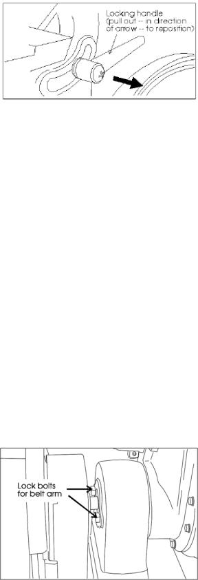
Figure 1: Locking handle for belt table
6.3 Using the indexing lock handle
The lock handle (Figure 1) is spring loaded and can be repositioned on its shaft to permit easy locking and unlocking.
To Reposition the Handle:
1.Pull outward against its spring.
2.Rotate the handle to the position you require.
3.Release the handle and its spring will return it to the correct operating position.
6.4 Adjusting the belt sander arm
The arm which holds the sanding belt can be positioned at a full vertical position, a full horizontal position, or at any angle in between which is convenient to the type of sanding you are doing.
A positive stop mechanism is used to permit quick adjustment to the vertical or horizontal positions.
 Never adjust the arm angle while the sander is running. Always turn off the motor before adjusting the arm angle.
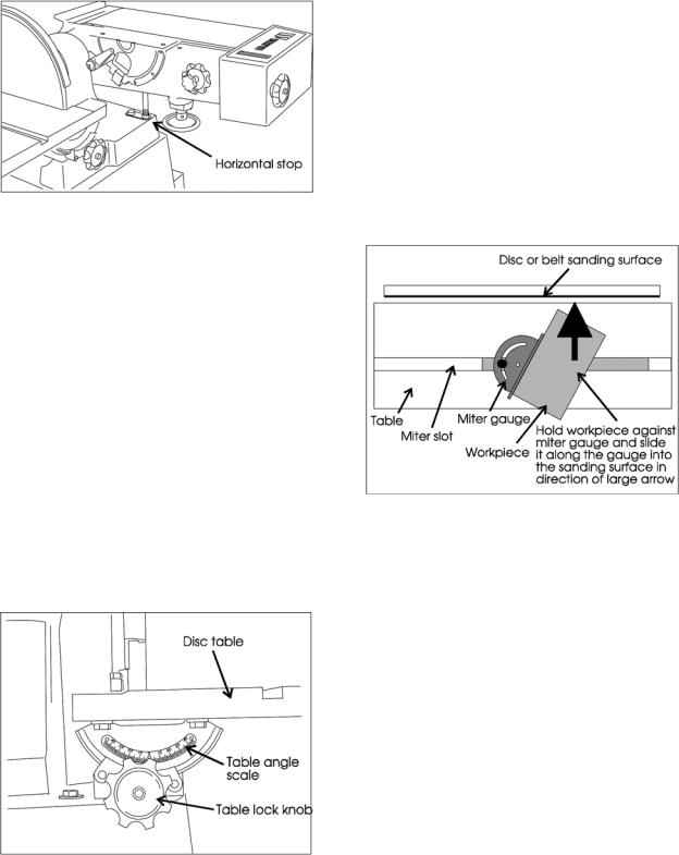
To adjust to vertical:
1.Unlock both lock bolts. These are located under the arbor cover.
2.Move the arm to vertical until it contacts its stop.
3.Tighten both lock bolts, and replace arbor cover.
Figure 2: Lock bolts for belt arm
8
To adjust to horizontal:
1.Unlock both lock bolts.
2.Move arm to horizontal until it contacts its stop. (See Figure 3.)
3.Tighten both lock bolts and replace arbor cover.
Figure 3: Arm at horizontal – note that the table is removed. The table may be removed or left in position, and may also be set to any angle to allow horizontal sanding of various angles.
To adjust arm to any angle between vertical and horizontal:
1.Unlock both lock bolts.
2.Use a machinist's protractor and level to set the arm to the required angle.
3.Tighten both lock bolts and replace arbor cover.
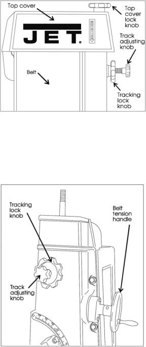
6.5 Adjusting disc sander table
 Never adjust the table angle while the sander is running. Always turn off the motor before adjusting table angle.
1.Unlock the two locking knobs underneath the table at each end. (See Figure 4.)
2.Using the pointer and scale, set the angle to any required angle between 20° upward and 45° downward.
3.Lock the two locking knobs underneath the table.
Figure 4: Disc sander table adjustment
6.6 Use of the Miter Gauge
The miter gauge can be used on either the disc or belt surfaces to sand accurate angles on workpieces. When using the gauge alone, you sand a single angle. However, by tilting the table and using the miter gauge in combination with the table tilt, it is possible to sand compound angles, as well.
When grinding a compound angle you should always check the accuracy of your setup by sanding a piece of scrap material before doing any finish sanding on the actual workpiece.
1.Set the angle you wish to sand using the scale on the miter gauge.
2.Tighten the miter gauge securely so the miter reference surface will not move while you are sanding.
3.Place the workpiece against the miter reference surface and slide it along the reference surface and into the sanding disc or belt. The basic method is shown in Figure 5, below.
Figure 5: Use of the miter system
9
7.0Maintenance
7.1Belt replacement
1.Disconnect the power to the machine to prevent accidental start-ups. If the machine is plugged into an outlet, unplug it. If the machine is hardwired to a branch circuit with a junction box, remove the fuse or trip the circuit breaker to the branch.
2.Remove the lock knob and top cover (See Figure 6).
Figure 6: Top cover components
3.Remove the side guard and table.
4.Release the belt tension by turning the tension handle in a counterclockwise direction (See Figure 7). If the handle is difficult to turn, perform
Track mechanism maintenance according to the instructions in section 7.2.
Figure 7: Belt adjustment components (Note top cover removed for removal and replacement of belt.)
5.Remove the belt.
6.Check the drums and platen for scoring or signs of wear which might require service or replacement.
7.Check the height of the platen with a straight edge. If it is not 1/32 inch above the drums, adjust it according to the instructions in Platen Replacement or Adjustment in the Machine Setup section of this manual.
8.Check the drums for looseness which might cause tracking problems. Correct any loose condition by tightening or replacing any parts as required.
9.Slip the new belt onto the drums and platen.
10.Adjust the tension handle clockwise until the belt is flat against the platen and there is no curling or buckling of the belt in the middle.
11.Turn the drums by hand to see if the belt tracks more-or-less true. JUST BECAUSE THE OLD BELT TRACKED CORRECTLY DOES NOT MEAN THE NEW BELT WILL. Always check the tracking when replacing a belt.
12.To adjust the tracking:
12.1.Plug the machine back into the outlet or reestablish power in the branch.
12.2.Loosen the tracking lock knob.
12.3.Jog the motor on and off as necessary to observe the tracking, and turn the tracking knob as necessary to make the belt track in the center
of the platen and drums. Turn the tracking knob clockwise to move the belt toward the right and counterclockwise to move the belt toward the left.
12.4.When the belt seems to be tracking correctly, turn the motor on and leave it running while fine tuning the tracking.
12.5.Lock the tracking lock knob.
12.6.When the lock knob is secure, turn the power off and disconnect the machine from the
outlet or branch as in Step 1, above.
13.Replace the table, side guard, top cover and lock knob by reversing steps 3 and 2, above.
14.If you have not already done so, reconnect the power to the machine and return it to service.
7.2 Track mechanism maintenance
While the use of a dust collection system can extend service intervals, an accumulation of dust will almost certainly require periodic cleaning of the tracking mechanism. The more continuous the use of the machine, the more frequently this maintenance should be performed.
As mentioned in the preceding section, the need for required maintenance is often indicated by difficulty in adjusting the tension/tracking mechanism.
1.With the belt removed according to the instructions in section 7.1 Belt replacement, pull out the upper tracking system and clean away all
10

built up material in the upper part of the bracket casting.
2.Take the two keys off of the idler pin bracket, wipe off, and re-grease.
3.Reverse the above steps to make the machine ready for reinstallation of the belt according to the
Belt replacement instructions.
7.3 Installing abrasive discs
1.Disconnect power to the machine to prevent accidental start-ups.
2.Peel off the old abrasive disc.
3.Clean the drive disc surface using naptha or a similar nonflammable solvent that will dry filmfree.
4.Pull the protective backing half off the new abrasive disc.
5.Position the new disc carefully so it is centered accurately on the drive disc. (See Figure 8.)
6.When accurately centered, remove the rest of the protective backing and press the abrasive disc firmly against the drive disc so complete adhesive contact is made.
7.Reconnect the power to the machine.
Figure 8: Installing new abrasive disc
7.4 Replacing the v-belt
1.Disconnect power to the machine to prevent accidental start-ups.
2.Remove the belt guard (Figure 9) and disc table.
3.Remove the table tilt lock knob (Figure 10).
4.Loosen the four motor bolts so the motor can slide on its plate.
Figure 9: Removing belt guard
Figure 10: Disc table lock knob
5.Remove the belt from the motor pulley.
6.Remove three of the base mounting bolts, then loosen the fourth bolt slightly. This allows you to rotate the machine on the machine base (See Figure 11).
7.Remove the two bolts, underneath the machine casting, that secure the disc guard to the casting (See Figure 11).
11
Loading...