


 Loading...
JET 690036, 690038, 691173, 691174, 691175 User Manual
...Operating Instructions and Parts Manual
Step-Pulley Turret Mill
Model JVM-836
JET |
|
427 New Sanford Road |
Part No. M-690036 |
LaVergne, Tennessee 37086 |
|
Ph.: 800-274-6848 |
Revision C 11/2014 |
www.jettools.com |
Copyright © 2014 JET |

1.0 Warranty and Service
JET warrants every product it sells against manufacturers’ defects. If one of our tools needs service or repair, please contact Technical Service by calling 1-800-274-6846, 8AM to 5PM CST, Monday through Friday.
Warranty Period
The general warranty lasts for the time period specified in the literature included with your product or on the official JET branded website.
•JET products carry a limited warranty which varies in duration based upon the product. (See chart below)
•Accessories carry a limited warranty of one year from the date of receipt.
•Consumable items are defined as expendable parts or accessories expected to become inoperable within a reasonable amount of use and are covered by a 90 day limited warranty against manufacturer’s defects.
Who is Covered
This warranty covers only the initial purchaser of the product from the date of delivery.
What is Covered
This warranty covers any defects in workmanship or materials subject to the limitations stated below. This warranty does not cover failures due directly or indirectly to misuse, abuse, negligence or accidents, normal wear-and-tear, improper repair, alterations or lack of maintenance. JET woodworking machinery is designed to be used with Wood. Use of these machines in the processing of metal, plastics, or other materials may void the warranty. The exceptions are acrylics and other natural items that are made specifically for wood turning.
Warranty Limitations
Woodworking products with a Five Year Warranty that are used for commercial or industrial purposes default to a Two Year Warranty. Please contact Technical Service at 1-800-274-6846 for further clarification.
How to Get Technical Support
Please contact Technical Service by calling 1-800-274-6846. Please note that you will be asked to provide proof of initial purchase when calling. If a product requires further inspection, the Technical Service representative will explain and assist with any additional action needed. JET has Authorized Service Centers located throughout the United States. For the name of an Authorized Service Center in your area call 1-800-274-6846 or use the Service Center Locator on the JET website.
More Information
JET is constantly adding new products. For complete, up-to-date product information, check with your local distributor or visit the JET website.
How State Law Applies
This warranty gives you specific legal rights, subject to applicable state law.
Limitations on This Warranty
JET LIMITS ALL IMPLIED WARRANTIES TO THE PERIOD OF THE LIMITED WARRANTY FOR EACH PRODUCT. EXCEPT AS STATED HEREIN, ANY IMPLIED WARRANTIES OF MERCHANTABILITY AND FITNESS FOR A PARTICULAR PURPOSE ARE EXCLUDED. SOME STATES DO NOT ALLOW LIMITATIONS ON HOW LONG AN IMPLIED WARRANTY LASTS, SO THE ABOVE LIMITATION MAY NOT APPLY TO YOU.
JET SHALL IN NO EVENT BE LIABLE FOR DEATH, INJURIES TO PERSONS OR PROPERTY, OR FOR INCIDENTAL, CONTINGENT, SPECIAL, OR CONSEQUENTIAL DAMAGES ARISING FROM THE USE OF OUR PRODUCTS. SOME STATES DO NOT ALLOW THE EXCLUSION OR LIMITATION OF INCIDENTAL OR CONSEQUENTIAL DAMAGES, SO THE ABOVE LIMITATION OR EXCLUSION MAY NOT APPLY TO YOU.
JET sells through distributors only. The specifications listed in JET printed materials and on official JET website are given as general information and are not binding. JET reserves the right to effect at any time, without prior notice, those alterations to parts, fittings, and accessory equipment which they may deem necessary for any reason whatsoever. JET® branded products are not sold in Canada by JPW Industries, Inc.
Product Listing with Warranty Period
90 Days – Parts; Consumable items; Light-Duty Air Tools
1 Year – Motors; Machine Accessories; Heavy-Duty Air Tools; Pro-Duty Air Tools
2 Year – Metalworking Machinery; Electric Hoists, Electric Hoist Accessories; Woodworking Machinery used for industrial or commercial purposes
5 Year – Woodworking Machinery
Limited Lifetime – JET Parallel clamps; VOLT Series Electric Hoists; Manual Hoists; Manual Hoist Accessories; Shop Tools; Warehouse & Dock products; Hand Tools
NOTE: JET is a division of JPW Industries, Inc. References in this document to JET also apply to JPW Industries, Inc., or any of its successors in interest to the JET brand.
2
2.0 |
Table of contents |
|
|
Section |
Page |
||
1.0 |
Warranty and Service..................................................................................................................................... |
2 |
|
2.0 |
Table of contents............................................................................................................................................ |
3 |
|
3.0 |
Safety warnings.............................................................................................................................................. |
4 |
|
4.0 |
About this manual .......................................................................................................................................... |
5 |
|
5.0 |
Specifications ................................................................................................................................................. |
6 |
|
6.0 |
JVM-836 Installation Layout ........................................................................................................................... |
7 |
|
7.0 |
Setup and Assembly ...................................................................................................................................... |
8 |
|
7.1 Unpacking .................................................................................................................................................. |
8 |
||
7.2 |
Contents of shipping container................................................................................................................... |
8 |
|
7.3 |
Site preparation .......................................................................................................................................... |
9 |
|
7.4 |
Lifting the mill ............................................................................................................................................. |
9 |
|
7.5 Completing assembly ................................................................................................................................. |
9 |
||
7.6 |
Lubrication................................................................................................................................................ |
10 |
|
8.0 |
Electrical connections .................................................................................................................................. |
10 |
|
8.1 Conversion from 115V to 230V (JVM-836-1 only)..................................................................................... |
10 |
||
8.2 Wire Sizes ................................................................................................................................................ |
10 |
||
9.0 |
Controls........................................................................................................................................................ |
11 |
|
10.0 Operation ................................................................................................................................................... |
12 |
||
10.1 |
Precautions ............................................................................................................................................ |
12 |
|
10.2 |
Clamping work piece to table ................................................................................................................. |
12 |
|
10.3 |
Changing speeds ................................................................................................................................... |
12 |
|
10.4 |
Fine feed ................................................................................................................................................ |
12 |
|
10.5 |
Draw bar operation; changing tooling..................................................................................................... |
13 |
|
11.0 Adjustments ............................................................................................................................................... |
13 |
||
11.1 |
Head movement: left and right ............................................................................................................... |
13 |
|
11.2 |
Positioning ram....................................................................................................................................... |
14 |
|
11.3 |
Gib adjustment ....................................................................................................................................... |
14 |
|
11.4 |
Ram wear plate adjustment.................................................................................................................... |
14 |
|
11.5 |
Table lead screw backlash adjustment .................................................................................................. |
14 |
|
12.0 Speed charts for JVM-836 ......................................................................................................................... |
16 |
||
13.0 Replacement Parts..................................................................................................................................... |
16 |
||
13.1.1 JVM-836 Head Assembly – Exploded View ........................................................................................ |
17 |
||
13.1.3 JVM-836 Head Assembly – Parts List................................................................................................. |
18 |
||
13.2.1 JVM-836 Upper Head Assembly – Exploded View ............................................................................. |
20 |
||
13.2.2 JVM-836 Upper Head Assembly – Parts List ...................................................................................... |
21 |
||
13.3.1 JVM-836 Leadscrew Assembly – Exploded View ............................................................................... |
23 |
||
13.3.2 JVM-836 Leadscrew Assembly – Parts List ........................................................................................ |
24 |
||
13.4.1 JVM-836 Base Assembly – Exploded View ........................................................................................ |
25 |
||
13.4.2 JVM-836 Base Assembly – Parts List ................................................................................................. |
26 |
||
13.5.1 JVM-836 One Shot Lubrication System – Exploded View .................................................................. |
28 |
||
13.5.2 One Shot Lubrication System – Parts List........................................................................................... |
28 |
||
14.0 Electrical Connections for JVM-836........................................................................................................... |
29 |
||
3

3.0 Safety warnings
1.Read and understand the entire owner's manual before attempting assembly or operation.
2.Read and understand the warnings posted on the machine and in this manual. Failure to comply with all of these warnings may cause serious injury.
3.Replace the warning labels if they become obscured or removed.
4.This turret mill is designed and intended for use by properly trained and experienced personnel only. If you are not familiar with the proper and safe operation of a turret mill, do not use until proper training and knowledge have been obtained.
5.Do not use this turret mill for other than its intended use. If used for other purposes, JET disclaims any real or implied warranty and holds itself harmless from any injury that may result from that use.
6.Always wear approved safety glasses/face shields while using this mill. Everyday eyeglasses only have impact resistant lenses; they are not safety glasses.
7.Before operating this machine, remove tie, rings, watches and other jewelry, and roll sleeves up past the elbows. Remove all loose clothing and confine long hair.
8.Non-slip safety footwear and anti-skid floor strips are recommended. Do not wear gloves.
9.Never place hands near or around a revolving tool or part.
10.Wear ear protectors (plugs or muffs) during extended periods of operation.
11.Some dust created by power sanding, sawing, grinding, drilling and other construction activities contain chemicals known to cause cancer, birth defects or other reproductive harm. Some examples of these chemicals are:
•Lead from lead based paint.
•Crystalline silica from bricks, cement and other masonry products.
•Arsenic and chromium from chemically treated lumber.
Your risk of exposure varies, depending on how often you do this type of work. To reduce your exposure to these chemicals, work in a well-ventilated area and work with approved safety equipment, such as face or dust masks
that are specifically designed to filter out microscopic particles.
12.Do not operate this machine while tired or under the influence of drugs, alcohol or any medication.
13.Make certain the switch is in the OFF position before connecting the machine to the power supply.
14.Make certain the machine is properly grounded.
15.Make all machine adjustments or maintenance with the machine unplugged from the power source.
16.Workpiece must be attached or clamped to the table. Never hold a workpiece with your hand.
17.Use correct spindle speed and table feed for the particular job.
18.Do not start machine with cutter in contact with workpiece.
19.Disengage power feed when not in use.
20.Remove adjusting keys and wrenches. Form a habit of checking to see that keys and adjusting wrenches are removed from the machine before turning it on.
21.Keep safety guards in place at all times when the machine is in use. If removed for maintenance purposes, use extreme caution and replace the guards immediately after completion of maintenance.
22.Check damaged parts. Before further use of the machine, a guard or other part that is damaged should be carefully checked to determine that it will operate properly and perform its intended function. Check for alignment of moving parts, binding of moving parts, breakage of parts, mounting and any other conditions that may affect its operation. A guard or other part that is damaged should be properly repaired or replaced.
23.Provide for adequate space surrounding work area and non-glare, overhead lighting.
24.Keep the floor around the machine clean and free of scrap material, oil and grease.
25.Keep visitors a safe distance from the work area. Keep children away.
26.Make your workshop child proof with padlocks, master switches or by removing starter keys.
27.Give your work undivided attention. Looking around, carrying on a conversation and “horseplay” are careless acts that can result in serious injury.
4
28.Maintain a balanced stance at all times so that you do not fall or lean against the cutter or other moving parts. Do not overreach or use excessive force to perform any machine operation.
29.Use the right tool at the correct speed and feed rate. Rotate spindle clockwise for righthand tools, counterclockwise for left-hand tools. Do not force a tool or attachment to do a job for which it was not designed. The right tool will do the job better and more safely.
30.Use recommended accessories; improper accessories may be hazardous.
31.Frequently clean this machine. Maintain tools with care. Keep cutters sharp and clean for the best and safest performance. Follow instructions for lubricating and changing accessories.
32.Turn off the machine before cleaning. Use a brush or compressed air to remove chips or debris — do not use your hands.
33.Do not stand on the machine. Serious injury could occur if the machine tips over.
34.Never leave the machine running unattended. Turn the power off and do not leave the machine until it comes to a complete stop.
35.Remove loose items and unnecessary work pieces from the area before starting the machine.
36.Don’t use in dangerous environment. Don’t use this machine in damp or wet locations, or expose it to rain. Keep work area well lighted.
37.Some coolants used for machining contain chemicals that may be hazardous to your health if not used properly. Read and understand all user information listed on the coolant container and protect yourself accordingly.
Familiarize yourself with the following safety notices used in this manual:
 This means that if precautions are not heeded, it may result in minor injury and/or possible machine damage.
 This means that if precautions are not heeded, it may result in serious, or possibly even fatal, injury.
4.0 About this manual
This manual is provided by JET, covering the safe operation and maintenance procedures for a JET Model JVM-836 Turret Mill. This manual contains instructions on installation, safety precautions, general operating procedures, maintenance instructions and parts breakdown. Your machine has been designed and constructed to provide consistent, long-term operation if used in accordance with the instructions set forth in this document.
If there are questions or comments, please contact your local supplier or JET. JET can also be reached at our web site: www.jettools.com.
Retain this manual for future reference. If the machine transfers ownership, the manual should accompany it.
 Read and understand the entire contents of this manual before attempting assembly or operation! Failure to comply may cause serious injury!
5
5.0 Specifications
Model Number................................................................................... |
JVM-836-1..................................... |
JVM-836-3 |
Stock Number......................................................................................... |
690036........................................... |
690038 |
Motor and Electricals: |
|
|
Motor type .................................................................................. |
TEFC induction............................... |
TEFC induction |
Horsepower................................................................................................ |
1-1/2.............................................. |
1-1/2 |
Phase............................................................................................................... |
1.................................................... |
3 |
Voltage....................................................................... |
115/230V (prewired 115V)....................................... |
230V only |
Cycle.......................................................................................................... |
60Hz.............................................. |
60Hz |
Listed FLA (full load amps)........................................................................... |
18/9............................................ |
4.7/5.7 |
Power Transfer............................................................................................. |
belt................................................. |
belt |
Motor Speed...................................................................................... |
1720 RPM............................... |
1720/840 RPM |
Sound Emission (tested at 3 ft. from machine): |
|
|
Without load.......................................................................................... |
75 dB............................................. |
75 dB |
With load......................................................................................... |
80-85 dB........................................ |
80-85 dB |
Head and Spindle: |
|
|
Spindle Taper ............................................................................................... |
R-8................................................. |
R-8 |
Quill Diameter............................................................................................ |
3-3/8”............................................. |
3-3/8” |
Number of Spindle Speeds................................................................................ |
5.................................................. |
10 |
Range of Spindle Speeds..................................................................... |
240-1550........................................ |
120-1550 |
Spindle Travel ................................................................................................. |
5”................................................... |
5” |
Head Movement ............................................................................... |
90° L and R.................................... |
90° L and R |
Maximum Distance Spindle to Table......................................................... |
13-3/4”........................................... |
13-3/4” |
Maximum Distance Spindle to Column ..................................................... |
15-3/4”........................................... |
15-3/4” |
Minimum Distance Spindle to Column ........................................................ |
5-1/4”............................................. |
5-1/4” |
Collet Capacity ................................................................................... |
1/8” – 7/8”....................................... |
1/8” – 7/8” |
Ram Travel.............................................................................................. |
10-1/2”........................................... |
10-1/2” |
Ram Rotation ................................................................................... |
90° L and R.................................... |
90° L and R |
Table: |
|
|
Table Size ................................................................................... |
7-7/8 x 35-3/4”................................ |
7-7/8 x 35-3/4” |
Longitudinal Table Travel ......................................................................... |
22-1/4”........................................... |
22-1/4” |
Table Cross Travel .................................................................................... |
9-1/2”............................................. |
9-1/2” |
T-Slots, Number ............................................................................................... |
3.................................................... |
3 |
T-Slots, Size................................................................................................. |
5/8”................................................ |
5/8” |
T-Slots, Spacing ........................................................................................ |
2-1/2”............................................. |
2-1/2” |
Table Weight Capacity.............................................................................. |
500 lb............................................. |
500 lb |
Knee Travel................................................................................................... |
14”................................................. |
14” |
Dimensions: |
|
|
Overall Dimensions, assembled ........................................... |
55”W x 52”D x 77”H........................ |
55”W x 52”D x 77”H |
Shipping Dimensions ........................................................... |
67”W x 56”D x 66”H........................ |
67”W x 56”D x 66”H |
Weights: |
|
|
Net Weight (approx.)............................................................................... |
1617 lb........................................... |
1610 lb |
Shipping Weight (approx)........................................................................ |
1700 lb........................................... |
1700 lb |
The specifications in this manual were current at time of publication, but because of our policy of continuous improvement, JET reserves the right to change specifications at any time and without prior notice, without incurring obligations.
6

6.0 JVM-836 Installation Layout
Figure 1
7
7.0Setup and Assembly
7.1Unpacking
Open shipping container and check for shipping damage. Report any damage immediately to your distributor and shipping agent. Do not discard any shipping material until the Turret Mill is assembled and running properly.
Compare the contents of your container with the following parts list to make sure all parts are intact. Missing parts, if any, should be reported to your distributor. Read the instruction manual thoroughly for assembly, maintenance and safety instructions.
NOTE: Some parts shown below may have come preinstalled on the mill.
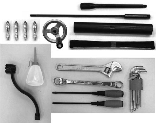
7.2 Contents of shipping container
Refer to Figure 2.
1 Turret Mill (not shown)
1 Flat Way Cover (rear)
1 Pleated Way Cover (front)
1 Knee Crank
1 Draw Bar
4 Handles
1Tool Box, containing:
1 Hex Key Set (1.5-10mm)
1 17/19mm Box Wrench
1 Cross Point Screw Driver #2
1 Flat Blade Screw Driver #2
1 |
Plastic Oil Bottle |
1 |
Handwheel |
1 |
Adjustable Wrench |
1 |
Operator’s Manual (not shown) |
1 |
Warranty Card (not shown) |
Figure 2: shipping contents
NOTE: If your mill is supplied with an optional Table Powerfeed and/or Digital Readout, be sure to consult the separate instruction materials that accompany them.
8
7.3 Site preparation
The mill must be placed on an even surface and bolted to the floor. Anchor bolts of sufficient size and length must be fastened to the floor according to the mill’s footprint. See the site installation diagram in Figure 1.
7.4 Lifting the mill
Finish removing the sides of the crate. Leave mill bolted to pallet until ready to move to its final location.
The preferred method for lifting mill is with a hook through the hoisting ring which is mounted atop the ram. Steady the mill to prevent it from spinning.
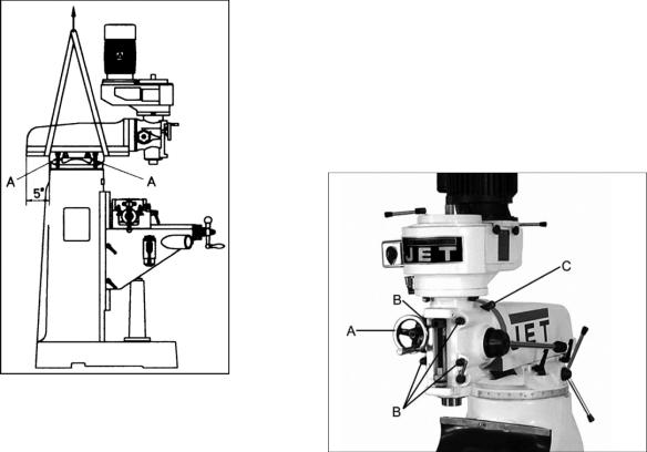
An alternate method for lifting mill is with a sling. Refer to Figure 3 for proper position of sling under ram. Note position of ram and that table has been moved against column. Tighten ram locking bolts (A, Figure 3) before lifting.
Figure 3: sling location
 Keep people a safe distance away while mill is being moved.
Carefully lift mill and move to a position over the anchor bolts. Lower mill over anchor bolts and check for level, with a machinist’s level placed on the table. Mill must be level back to front and side to side. Shim if necessary, but remember that mill must be supported equally at all four corners. Check for level before tightening anchor bolt nuts, and check again after tightening them.
It is advisable when placing the mill on a concrete floor to use grout (thin mortar) to correct any unevenness in the concrete and provide a solid foundation at all points.
 Mill must be supported equally under all four corners. Failure to comply may cause the column to twist and put a bind in the ways.
7.5 Completing assembly
(Note: If the mill head is already upright, skip to step 5 below. Otherwise, begin with step 1.)
 Before attempting to raise mill head, familiarize yourself with instructions in section 11.1, for procedures to safely raise and set up the mill head.
1.Remove handwheel (A, Figure 4).
2.Loosen four hexagonal nuts (B, Figure 4) about 1/2 turn each counterclockwise, just enough to allow rotation of head. Do not remove these nuts unless you are prepared to remove the head.
3.Apply upward pressure on motor by hand to relieve pressure on worm mechanism, and use a 19mm socket and breaker bar to turn worm nut (C, Figure 4) and raise head to upright position.
4.Slightly tighten nuts (B, Figure 4); not torqued, just snug for now. Before operating mill, follow procedures in section 11.1 to verify angle settings and properly tighten the four nuts.
Figure 4
5.Use mineral spirits, kerosene or other cleaning solvent, to remove all rust-proofing from where it may have been applied. This is important; moving the table or any other components before removing rust proofing will only put rust proofing where you don’t want it. Do not use gasoline, paint thinner, or lacquer thinner; these will damage painted surfaces.
9
6.Lubricate exposed ways (see sect. 7.6), then move each unit (table and ram) to the opposite limit stop, and clean and lubricate the newly exposed ways. Loosen bolts to unlock ram and move it forward and backward to the full length in order to clean and lubricate.
7.Cover all machined surfaces with a film of light machine tool oil to inhibit rust.
8.Remove wood block from below knee.
Some of the following steps may have already been performed on the machine. If so, ignore the instructions related to those particular steps. Otherwise, perform them in the order listed.
9.Install the two table traverse handles and one cross-feed handle on their respective shafts. Tighten each handle using a wrench on the flats.
10.Remove any rust proofing from drawbar. Install drawbar with its washer into spindle center through top of head assembly. When installing tool into spindle, lock spindle and tighten drawbar using provided wrench.
11.Slide the fine feed handwheel over the hub and push it back until its roll pin engages hole in hub, and handwheel is flush with hub surface.
12.Place coarse feed handle on feed shaft, aligning roll pin with a hole. Tap handle lightly until it is flush against hub surface.
13.Install elevating (knee) crank on its shaft.
14.Install rubber way covers at front and behind table.
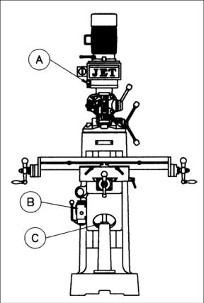
7.6 Lubrication
 Do not operate this milling machine before fully lubricating it. Failure to comply may damage machine.
Refer to Figure 5.
A.Spindle bearings – Fill oil cup once daily with Mobil DTE® Oil Light.
B.Oil Pump – Fill reservoir as needed by removing cap on top of tank and filling with Mobil Vactra Oil No. 2. Pump oil release handle once for every hour of operation. Way surfaces and leadscrews are lubricated in this manner.
C.Knee Leadscrew – Lubricate with Mobilith® AW2 once a week.
Figure 5: lubrication
8.0 Electrical connections
 All electrical connections must be made by a qualified electrician in compliance with all relevant codes. This machine must be properly grounded. Failure to comply may result in serious injury.
Confirm that power at the site matches power requirements of the mill before connecting to power source.
8.1Conversion from 115V to 230V (JVM-836-1 only)
To convert from 115V to 230V operation, remove junction box cover on motor and change the wires according to diagram found on inside of cover.
Similar diagrams are found in section 14.0 of this manual. Note: If discrepancies arise, diagrams on machine take precedence.
10
Loading...