


 Loading...
Operating Instructions and Parts Manual
16-speed Woodworking Drill Press
Models JDP-15F, JDP-15B
JET |
|
427 New Sanford Road |
Part No. M-716250 |
LaVergne, Tennessee 37086 |
|
Ph.: 800-274-6848 |
Edition 4 07/2017 |
www.jettools.com |
Copyright © 2017 JET |

1.0 Warranty and Service
JET® warrants every product it sells against manufacturers’ defects. If one of our tools needs service or repair, please contact Technical Service by calling 1-800-274-6846, 8AM to 5PM CST, Monday through Friday.
Warranty Period
The general warranty lasts for the time period specified in the literature included with your product or on the official JET branded website.
•JET products carry a limited warranty which varies in duration based upon the product. (See chart below)
•Accessories carry a limited warranty of one year from the date of receipt.
•Consumable items are defined as expendable parts or accessories expected to become inoperable within a reasonable amount of use and are covered by a 90 day limited warranty against manufacturer’s defects.
Who is Covered
This warranty covers only the initial purchaser of the product from the date of delivery.
What is Covered
This warranty covers any defects in workmanship or materials subject to the limitations stated below. This warranty does not cover failures due directly or indirectly to misuse, abuse, negligence or accidents, normal wear-and-tear, improper repair, alterations or lack of maintenance. JET woodworking machinery is designed to be used with Wood. Use of these machines in the processing of metal, plastics, or other materials outside recommended guidelines may void the warranty. The exceptions are acrylics and other natural items that are made specifically for wood turning.
Warranty Limitations
Woodworking products with a Five Year Warranty that are used for commercial or industrial purposes default to a Two Year Warranty. Please contact Technical Service at 1-800-274-6846 for further clarification.
How to Get Technical Support
Please contact Technical Service by calling 1-800-274-6846. Please note that you will be asked to provide proof of initial purchase when calling. If a product requires further inspection, the Technical Service representative will explain and assist with any additional action needed. JET has Authorized Service Centers located throughout the United States. For the name of an Authorized Service Center in your area call 1-800-274-6846 or use the Service Center Locator on the JET website.
More Information
JET is constantly adding new products. For complete, up-to-date product information, check with your local distributor or visit the JET website.
How State Law Applies
This warranty gives you specific legal rights, subject to applicable state law.
Limitations on This Warranty
JET LIMITS ALL IMPLIED WARRANTIES TO THE PERIOD OF THE LIMITED WARRANTY FOR EACH PRODUCT. EXCEPT AS STATED HEREIN, ANY IMPLIED WARRANTIES OF MERCHANTABILITY AND FITNESS FOR A PARTICULAR PURPOSE ARE EXCLUDED. SOME STATES DO NOT ALLOW LIMITATIONS ON HOW LONG AN IMPLIED WARRANTY LASTS, SO THE ABOVE LIMITATION MAY NOT APPLY TO YOU.
JET SHALL IN NO EVENT BE LIABLE FOR DEATH, INJURIES TO PERSONS OR PROPERTY, OR FOR INCIDENTAL, CONTINGENT, SPECIAL, OR CONSEQUENTIAL DAMAGES ARISING FROM THE USE OF OUR PRODUCTS. SOME STATES DO NOT ALLOW THE EXCLUSION OR LIMITATION OF INCIDENTAL OR CONSEQUENTIAL DAMAGES, SO THE ABOVE LIMITATION OR EXCLUSION MAY NOT APPLY TO YOU.
JET sells through distributors only. The specifications listed in JET printed materials and on official JET website are given as general information and are not binding. JET reserves the right to effect at any time, without prior notice, those alterations to parts, fittings, and accessory equipment which they may deem necessary for any reason whatsoever. JET® branded products are not sold in Canada by JPW Industries, Inc.
Product Listing with Warranty Period
90 Days – Parts; Consumable items; Light-Duty Air Tools
1 Year – Motors; Machine Accessories; Heavy-Duty Air Tools; Pro-Duty Air Tools
2 Year – Metalworking Machinery; Electric Hoists, Electric Hoist Accessories; Woodworking Machinery used for industrial or commercial purposes
5 Year – Woodworking Machinery
Limited Lifetime – JET Parallel clamps; VOLT Series Electric Hoists; Manual Hoists; Manual Hoist Accessories; Shop Tools; Warehouse & Dock products; Hand Tools
NOTE: JET is a division of JPW Industries, Inc. References in this document to JET also apply to JPW Industries, Inc., or any of its successors in interest to the JET brand.
2
2.0 |
Table of contents |
|
||
Section |
|
Page |
||
1.0 Warranty and Service..................................................................................................................................... |
2 |
|||
2.0 |
Table of contents............................................................................................................................................ |
3 |
||
3.0 IMPORTANT SAFETY INSTRUCTIONS ....................................................................................................... |
4 |
|||
4.0 |
About this manual .......................................................................................................................................... |
5 |
||
5.0 |
Specifications ................................................................................................................................................. |
6 |
||
5.1 |
Base mounting holes for JDP-15F/15B ...................................................................................................... |
7 |
||
6.0 Setup and assembly....................................................................................................................................... |
8 |
|||
6.1 |
Unpacking .................................................................................................................................................. |
8 |
||
6.2 |
Shipping contents....................................................................................................................................... |
8 |
||
6.3 |
Additional tools required for assembly ....................................................................................................... |
8 |
||
6.4 |
Location...................................................................................................................................................... |
9 |
||
6.5 |
Assembly.................................................................................................................................................... |
9 |
||
6.6 |
Chuck key and wrench storage ................................................................................................................ |
11 |
||
7.0 |
Electrical connections .................................................................................................................................. |
11 |
||
7.1 |
Grounding instructions ............................................................................................................................. |
11 |
||
7.2 |
Extension cords........................................................................................................................................ |
12 |
||
8.0 |
Adjustments ................................................................................................................................................. |
12 |
||
8.1 |
Tools needed for adjustments .................................................................................................................. |
12 |
||
8.2 |
Table movement....................................................................................................................................... |
12 |
||
8.3 |
Table insert leveling ................................................................................................................................. |
13 |
||
8.4 |
Table slots ................................................................................................................................................ |
13 |
||
8.5 |
Chuck and arbor removal ......................................................................................................................... |
13 |
||
8.6 |
Installing bits............................................................................................................................................. |
13 |
||
8.7 |
Changing spindle speeds ......................................................................................................................... |
14 |
||
8.8 |
Depth stop ................................................................................................................................................ |
14 |
||
8.9 |
Quill retraction lock................................................................................................................................... |
15 |
||
8.10 |
Laser adjustment.................................................................................................................................... |
15 |
||
8.11 |
LED work light ........................................................................................................................................ |
16 |
||
9.0 |
Operating controls........................................................................................................................................ |
16 |
||
9.1 |
Control panel ............................................................................................................................................ |
16 |
||
9.2 |
Safety key................................................................................................................................................. |
17 |
||
10.0 |
Operation ................................................................................................................................................... |
17 |
||
10.1 Work piece positioning ........................................................................................................................... |
17 |
|||
10.2 |
General Inspection ................................................................................................................................. |
17 |
||
10.3 |
Speed settings........................................................................................................................................ |
17 |
||
11.0 User-maintenance...................................................................................................................................... |
17 |
|||
11.1 |
Belt replacement .................................................................................................................................... |
18 |
||
11.2 |
Return spring.......................................................................................................................................... |
18 |
||
11.3 |
Additional servicing ................................................................................................................................ |
18 |
||
12.0 Speed chart................................................................................................................................................ |
19 |
|||
13.0 |
Troubleshooting the JDP-15F/15B............................................................................................................. |
20 |
||
14.0 Replacement Parts..................................................................................................................................... |
20 |
|||
14.1.1 |
JDP-15F Drill Press – Exploded View ................................................................................................. |
21 |
||
14.1.2 |
JDP-15F Drill Press – Parts List.......................................................................................................... |
22 |
||
14.2.1 |
JDP-15B Drill Press – Exploded View................................................................................................. |
26 |
||
14.2.2 |
JDP-15B Drill Press – Parts List.......................................................................................................... |
27 |
||
15.0 |
Electrical Connections – JDP-15F/15B Drill Press..................................................................................... |
31 |
||
3

3.0 IMPORTANT SAFETY
INSTRUCTIONS
When using an electrical appliance, basic precautions should always be followed, including the following:
READ ALL INSTRUCTIONS BEFORE USING THIS DRILL PRESS.
1.Read and understand the entire owner's manual before attempting assembly or operation.
2.Read and understand the warnings posted on the machine and in this manual. Failure to comply with all of these warnings may cause serious injury.
3.Replace the warning labels if they become obscured or removed.
4.This drill press is designed and intended for use by properly trained and experienced personnel only. If you are not familiar with the proper and safe operation of a drill press, do not use until proper training and knowledge have been obtained.
5.Do not use this drill press for other than its intended use. If used for other purposes, JET disclaims any real or implied warranty and holds itself harmless from any injury that may result from that use.
6.Always wear ANSI Z87.1 approved safety glasses or face shield while using this drum sander. (Everyday eyeglasses only have impact resistant lenses; they are not safety glasses.)
7.Before operating this drill press, remove tie, rings, watches and other jewelry, and roll sleeves up past the elbows. Remove all loose clothing and confine long hair. Non-slip footwear or anti-skid floor strips are recommended. Do not wear gloves.
8.Wear ear protectors (plugs or muffs) during extended periods of operation.
9.Drilling, sawing, sanding or machining wood products generates wood dust and other substances known to the State of California to cause cancer. Avoid inhaling dust generated from wood products or use a dust mask or other safeguards to avoid inhaling dust generated from wood products.
10.Wood products emit chemicals known to the State of California to cause birth defects or other reproductive harm. (California Health and Safety Code Section 25249.6)
11.Do not operate this machine while tired or under the influence of drugs, alcohol or any medication.
12.Make certain the switch is in the OFF position before connecting the machine to the power supply.
13.Make certain the machine is properly grounded.
14.Make all machine adjustments or maintenance with the machine unplugged from the power source.
15.Remove adjusting keys and wrenches. Form a habit of checking to see that keys and adjusting wrenches are removed from the machine before turning it on.
16.Do not start the drill press while the cutting tool is in contact with the workpiece.
17.Secure workpiece firmly against table and make sure table is locked, before drilling.
18.Keep safety guards in place at all times when the machine is in use. If removed for maintenance purposes, use extreme caution and replace the guards immediately after completion of maintenance.
19.Check damaged parts. Before further use of the machine, a guard or other part that is damaged should be carefully checked to determine that it will operate properly and perform its intended function. Check for alignment of moving parts, binding of moving parts, breakage of parts, mounting and any other conditions that may affect its operation. A guard or other part that is damaged should be properly repaired or replaced.
20.Provide for adequate space surrounding work area and non-glare, overhead lighting.
21.Keep the floor around the machine clean and free of scrap material, oil and grease.
22.Keep visitors a safe distance from the work area. Keep children away.
23.Make your workshop child proof with padlocks, master switches or by removing starter keys.
24.Give your work undivided attention. Looking around, carrying on a conversation and “horseplay” are careless acts that can result in serious injury.
25.Maintain a balanced stance at all times so that you do not fall into the bit or other moving parts. Do not overreach or use excessive force to perform any machine operation.
26.Use the right tool at the correct speed and feed rate. Do not force a tool or attachment to do a job for which it was not designed. The right tool will do the job better and more safely.
4
27.Use recommended accessories; improper accessories may be hazardous.
28.Maintain tools with care. Keep tools sharp and clean for the best and safest performance. Follow instructions for lubricating, and changing accessories.
29.Turn off the machine before cleaning. Use a brush or compressed air to remove chips or debris — do not use your hands.
30.Do not stand on the machine. Serious injury could occur if the machine tips over.
31.Never leave the machine running unattended. Turn the power off and do not leave the machine until it comes to a complete stop.
32.Remove loose items and unnecessary work pieces from the area before starting the machine.
33.Don’t use in dangerous environment. Don’t use power tools in damp or wet location, or expose them to rain. Keep work area well lighted.
Familiarize yourself with the following safety notices used in this manual:
 This means that if precautions are not heeded, it may result in minor injury and/or possible machine damage.
 This means that if precautions are not heeded, it may result in serious, or possibly even fatal, injury.
4.0 About this manual
This manual is provided by JET, covering the safe operation and maintenance procedures for a JET Model JDP15F and JDP-15B Drill Press. This manual contains instructions on installation, safety precautions, general operating procedures, maintenance instructions and parts breakdown. Your machine has been designed and constructed to provide consistent, long-term operation if used in accordance with the instructions as set forth in this document.
This manual is not intended to be an exhaustive guide to drill press operational methods, use of jigs or aftermarket accessories, choice of bits or wood stock, etc. Additional knowledge can be obtained from experienced users or trade articles. Whatever accepted methods are used, always make personal safety a priority.
If there are questions or comments, please contact your local supplier or JET. JET can also be reached at our web site: www.jettools.com.
Retain this manual for future reference. If the machine transfers ownership, the manual should accompany it.
 Read and understand the entire contents of this manual before attempting assembly or operation! Failure to comply may cause serious injury!
5
5.0 Specifications
Model number |
.......................................................................JDP-15F |
.....................................................JDP-15B |
Stock number .......................................................................... |
716250 |
....................................................... 716200 |
Style ................................................................................. |
Floor mount .............................................. |
Bench mount |
Motor and electricals:
Motor type………………………………………totally enclosed fan cooled, induction, capacitor start ..................
Horsepower .......................................................................... |
|
|
3/4 HP |
........................................................ 3/4 HP |
Phase..................................................................................... |
|
|
single |
..........................................................single |
Voltage............................................................................. |
|
|
115V only ................................................... |
115V only |
Cycle....................................................................................... |
|
|
60Hz ........................................................... |
60Hz |
Listed FLA (full load amps) ..................................................... |
|
9.0 A ........................................................... |
9.0 A |
|
Starting amps........................................................................... |
|
|
18 A ............................................................ |
18 A |
Running amps (no load) ............................................................ |
|
|
3 A .............................................................. |
3 A |
Start capacitor..................................................... |
|
|
150MFD, 125VAC ...................................... |
150MFD, 125VAC |
Run capacitor........................................................... |
|
|
40μF, 250VAC ........................................... |
40 μ F, 250VAC |
Power transfer ............................................................ |
|
|
2 poly v-belts .............................................. |
2 poly v-belts |
On/off switch .................... |
push button with safety key, paddle stop ... |
push button with safety key, paddle stop |
||
Motor speed.................................................................... |
|
|
1720 RPM .................................................. |
1720 RPM |
Power cord.................................................. |
|
|
16 AWG, 6 ft. (183 cm) .............................. |
16 AWG, 6 ft. (183 cm) |
Power plug installed.................................... |
|
|
115V, 15A with ground ............................... |
115V, 15A with ground |
Recommended circuit size 1 .................................................... |
|
15 A ............................................................ |
15 A |
|
Sound emission 2 .............................. |
|
75dB at 39” (1m) without load .................... |
75dB at 39” (1m) without load |
|
Laser system ....................................................................... |
|
|
Class II ...................................................... |
Class II |
Head and Capacities: |
|
|
|
|
Swing 3........................................................................ |
|
|
15” (387mm) .............................................. |
15” (387mm) |
Chuck style and shank capacity ....................... |
|
keyed, 5/8” (16mm) .................................... |
keyed, 5/8” (16mm) |
|
Chuck arbor taper ....................................................... |
|
|
JT-3 to MT-2 .............................................. |
JT - 3 to MT-2 |
Spindle taper........................................................................... |
|
|
MT-2 ........................................................... |
MT-2 |
Spindle travel, maximum ......................................... |
|
|
3-1/8” (80 mm) ........................................... |
3 - 1/8” (80 mm) |
Spindle travel per one revolution of handle |
............. 3-1/8” (80 mm) ........................................... |
3 - 1/8” (80 mm) |
||
Quill diameter........................................................... |
|
|
1-7/8” (47 mm) ........................................... |
1 - 7/8” (47 mm) |
Number of spindle speeds ........................................................... |
|
16 ............................................................... |
16 |
|
Maximum no-load speed range ........................... |
|
210 to 3500 RPM ....................................... |
210 to 3500 RPM |
|
Maximum spindle to table distance...................... |
|
30-5/8” (778 mm) ....................................... |
18 - 1/2” (471 mm) |
|
Maximum spindle to base distance.................... |
|
46 -1/2” (1180 mm) ....................................... |
26 - 7/8” (683 mm) |
|
Maximum chuck to table distance........................ |
|
26-5/8” (676 mm) ....................................... |
14 - 1/2” (368 mm) |
|
Maximum chuck to base distance...................... |
|
42 -1/2” (1080 mm) ....................................... |
22 - 7/8” (581 mm) |
|
Work lamp................................................. |
|
integrated, pivoting LED ............................. |
integrated, pivoting LED |
|
Depth stop type.................................................................... |
|
|
internal ....................................................... |
internal |
Materials: |
|
|
|
|
Head .................................................................................. |
|
|
cast iron ..................................................... |
cast iron |
Table...................................................... |
|
precision-ground cast iron .......................... |
precision - ground cast iron |
|
Table insert .............................................................................. |
|
|
MDF ........................................................... |
MDF |
Column .................................................................................... |
|
|
steel ........................................................... |
steel |
Base................................................................................... |
|
|
cast iron ..................................................... |
cast iron |
Table: |
|
|
|
|
Table size .................................. |
12-1/2” L x 17” W (320 x 435 mm) ............. |
12 - 1/2” L x 17” W (320 x 435 mm) |
||
Table slots (4) .................................. |
|
2-3/4”L x 5/8” W (70 x 15 mm) ................... |
2 - 3/4”L x 5/8” W (70 x 15 mm) |
|
Table T-slots (2)................................ |
|
1/2” W x 5/8” D (13 x 15 mm) ..................... |
1/2” W x 5/8” D (13 x 15 mm) |
|
Distance between T-slots (centers) ..................... |
|
10-5/8” (270 mm) ....................................... |
10 - 5/8” (270 mm) |
|
Table tilt ................................................................. |
|
|
45 deg. L and R ......................................... |
45 deg. L and R |
Table rotation around column ............................................ |
|
360 deg. ..................................................... |
360 deg. |
|
Table elevating system .................................... |
|
|
worm gear with rack ................................... |
worm gear with rack |
Table insert ......................................... |
|
3-3/4” x 3-3/4” (95 x 95 mm) ...................... |
3 - 3/4” x 3 - 3/4” (95 x 95 mm) |
|
Recommended maximum weight on table.................. |
66 lb. (30 kg) .............................................. |
66 lb. (30 kg) |
||
6
Base and Column: |
|
|
|
Base size ......................................... |
18-7/8”L x 11-3/8”W x 2-5/8”H |
......................... 18”L x 11-3/8”W x 2-1/4”H |
|
........................................................................ |
|
(480 x 288 x 66 mm) |
.................................. (460 x 288 x 56 mm) |
Base working surface ...................... |
8”L x 9-1/2”W (200 x 240 mm) ................. |
8” L x 9 - 1/2” W (200 x 240 mm) |
|
Base slots (2)................................ |
5/8”W x 6-5/16”L (16 x 160 mm) ................ |
5/8”W x 6 - 5/16”L (16 x 160 mm) |
|
Distance between base slots (centers) |
........................ 5” (126 mm) ............................................... |
5” (126 mm) |
|
Column diameter ............................................ |
|
2 - 7/8” (ø73 x T3mm) .................................. |
2-7/8” (ø73 x T3mm) |
Dimensions and Weights: |
|
|
|
Overall dimensions, assembled........... |
|
26 - 5/8”L x 17”W x 63-7/8”H ....................... |
26 - 5/8”L x 17”W x 43-7/8”H |
.................................................................... |
|
(677 x 434 x 1623 mm) .............................. |
(677 x 434 x 1115 mm) |
Shipping dimensions...................... |
58”L x 24-7/16”W x 12-13/16”H ................ |
36 - 1/2”L x 33-1/4”W x 12-13/16” |
|
.................................................................... |
|
(1475 x 625 x 320 mm) ................................ |
(925 x 845 x 325 mm) |
Net weight (approximate)........................................ |
|
172 lb (78.2 kg) .......................................... |
154 lb (70.2 kg) |
Shipping weight (approximate) ............................... |
|
183 lb (83.2 kg) ....................................... |
165.5 lb (75.2 kg) |
L = length; W = width; H = height
1Subject to local and national electrical codes.
2The specified values are emission levels and are not necessarily to be seen as safe operating levels. As workplace conditions vary, this information is intended to allow the user to make a better estimation of the hazards and risks involved only.
3Swing is twice the distance from column to spindle center (i.e., the maximum diameter of workpiece that can be drilled to its center).
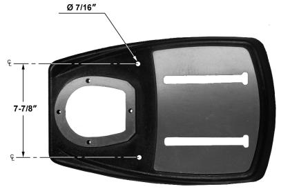
5.1 Base mounting holes for JDP-15F/15B
Figure 1: Base mounting holes
The specifications in this manual were current at time of publication, but because of our policy of continuous improvement, JET reserves the right to change specifications at any time and without prior notice, without incurring obligations.
7
6.0 Setup and assembly
 Read and understand all assembly instructions before attempting assembly. Failure to comply may cause serious injury.
6.1 Unpacking
Separate all parts from the packing material. Check each part against sect. 6.2 Shipping contents and make certain that all items are accounted for before discarding any packing material. Report any shortages or shipping damage to your JET distributor.
Exposed metal surfaces on the drill press have been factory-coated with a protectant. Remove this with a soft rag moistened with a light solvent, such as kerosene or WD-40®. Do not use an abrasive pad, and do not use gasoline, paint thinner or acetone – these will damage plastic components and painted surfaces.
After assembly, exposed metal surfaces on the drill press should be periodically coated with a light application of paste wax or other rust-protectant.
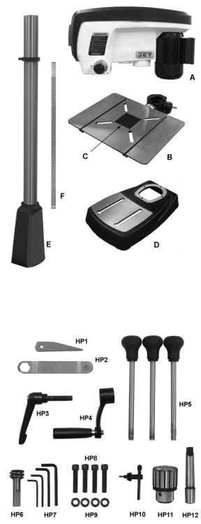
6.2 Shipping contents
Refer to Figures 2 and 3.
1 Head assembly – A
1 Table and bracket assembly – B
1 Table insert – C
1 Base – D
1 Column and foot assembly – E
1 Rack – F
1 Owner’s manual (not shown)
1 Warranty card (not shown)
Hardware package (JDP17-HP2):
1 Drift Key – HP1
1 Table locking wrench 24mm – HP2
1 Handle, column lock – HP3
1 Handle, table elevating – HP4
3Downfeed handles – HP5
1Worm – HP6
3Hex keys, 3/4/5/6mm – HP7
4Socket head cap screws, M8x50 – HP8
4Flat washers, 8mm – HP9
1Chuck key – HP10
1Chuck 5/8” – HP11
1Arbor – HP12
6.3 Additional tools required for assembly
(not provided)
Rubber mallet (or hammer and wood block) 13mm wrench (for table pin nut) Cross-point (Phillips) screwdriver
Figure 2: Contents of shipping container (JDP-15F column and rack shown)
Figure 3: Hardware Package (p/n JDP17-HP2)
8

6.4 Location
The drill press should be placed in a dry area, with a level floor and good lighting. Provide enough space around drill press to allow for operations and any adjustments or servicing.
6.5 Assembly
Do not connect drill press to power source until machine has been fully assembled.
1.Place the base upon a level floor. It may be secured to the floor with lag screws (not provided) through the two holes in the base. Refer to Figure 1 for hole spacing.
If you do not wish permanent attachment to the floor, the drill press can be bolted to a plywood panel which will serve as an expanded base and further stabilize the machine. Use a high grade of plywood (not particle board) at least 3/4" thick. It should be large enough to prevent vibration, sliding or moving of drill press during operation. Do not use a mobile base with this machine.
2.Make sure the set screw (Figure 4) is tight against the column. Tighten further if needed, using a 5mm hex key.
Figure 4
3.Lay the column assembly down on an elevated surface (such as the included polystyrene packaging). Attach base to column foot with four M8x50 socket head cap screws and four 8mm flat washers (HP8/HP9, Figure 5), using a 6mm hex key. NOTE: Align base and foot so that their edges are flush.
4.Tighten screws firmly.
Figure 5
5.Set column assembly upright.
6.Insert the worm shaft (HP6, Figure 6) through the hole in the table bracket as far as it will go, meshing the worm with the teeth on the gear.
Figure 6
7.Position rack (F, Figure 7) into the slot in table bracket. The longer flat portion of the rack should be at the top, the short flat portion at the bottom. Mesh the rack teeth with the worm gear in the table bracket.
8.With the aid of a second person, hold the rack in the slot, while setting the table bracket over the top of the column. Then slide table bracket and rack together down the column until the lower end of the rack rests in the lip of the holder, as shown in Figure 7.
9

Figure 7
9.Place stop collar (G, Figure 8) onto column and slide it down over top end of rack. Orient the stop collar so that chuck key holder (H) is in desired position around the column.
10.Tighten set screw (J) with a 4mm hex key.
11.Push chuck key into holder (inset, Figure 8)
Figure 8
12.Slide table elevating handle (HP4, Figure 9) onto protruding shaft of worm. Make sure the set screw in the handle aligns with the flat on the worm shaft.
13.Tighten set screw (K) in table elevating handle with 4mm hex key.
14.Mount column locking handle (HP3, Figure 9) to rear of table bracket. The quickest way to install this is to remove the handle by unscrewing the screw with its spring (L). Insert the bolt (N) into the table bracket hole, then reinstall handle (M), spring and screw (L).
Note: The locking handle (HP3) is adjustable. To reposition, pull out on the handle and rotate it, then release it, making sure it reseats itself on the bolt head.
10
Figure 9
 The head assembly is heavy! To avoid injury and/or damage to equipment, lift the head onto the column only with additional assistance!
15.With the aid of a second person, carefully lift the head assembly and place it onto the column. Slide head down as far as it will go. Rotate head assembly until the sides of the belt cover are parallel with the sides of the base.
16.Tighten the two set screws (O, Figure 10) with a 5mm hex key until they are snug.
Figure 10
17.Install three downfeed handles (HP5, Figure 11) into hub by screwing them in completely. A flat is provided on each handle for a 9mm wrench or pliers to help tighten if needed.
Figure 11
18.Thoroughly clean spindle, arbor and chuck (Figure 12) with a soft rag and solvent, such as mineral spirits.
Loading...