


Range

INSTALLATION INSTRUCTIONS
30" (76.2 CM) GAS DOWNDRAFT SLIDE-IN RANGES
INSTRUCTIONS POUR L’INSTALLATION DES CUISINIÈRES
À GAZ ENCASTRABLES AVEC ÉVACUATION
PAR LE BAS DE 30" (76,2 CM)
Table of Contents Table des matières
RANGE SAFETY .............................................................................2
INSTALLATION REQUIREMENTS................................................4
Tools and Parts ............................................................................4
Location Requirements................................................................5
Venting Requirements..................................................................6
Venting Methods..........................................................................7
Calculating Vent System Length..................................................8
Electrical Requirements ...............................................................8
Gas Supply Requirements...........................................................9
Countertop Preparation .............................................................10
INSTALLATION INSTRUCTIONS................................................10
Unpack Range............................................................................10
Adjust Leveling Legs..................................................................10
Install Anti-Tip Bracket...............................................................11
Install Downdraft System...........................................................12
Make Gas Connection ...............................................................16
Connect Range to Downdraft System.......................................17
Electronic Ignition System .........................................................19
Complete Installation .................................................................22
GAS CONVERSIONS....................................................................23
LP Gas Conversion ....................................................................23
Natural Gas Conversion.............................................................27
SÉCURITÉ DE LA CUISINIÈRE ...................................................32
EXIGENCES D'INSTALLATION...................................................34
Outillage et pièces......................................................................34
Exigences d’emplacement.........................................................35
Exigences concernant l’évacuation ...........................................36
Méthodes d’évacuation..............................................................37
Calcul de la longueur effective du circuit d’évacuation.............38
Spécifications électriques ..........................................................39
Spécifications de l’alimentation en gaz .....................................39
Préparation du plan de travail....................................................41
INSTRUCTIONS D’INSTALLATION.............................................41
Déballage de la cuisinière ..........................................................41
Réglage des pieds de nivellement.............................................41
Installation de la bride antibasculement ....................................42
Installation du circuit d’évacuation par le bas ...........................43
Raccordement au gaz................................................................47
Raccordement de la cuisinière au circuit d’évacuation
par le bas....................................................................................48
Système d'allumage électronique..............................................51
Achever l’installation ..................................................................53
CONVERSIONS POUR CHANGEMENT DE GAZ.......................54
Conversion pour l'alimentation au propane ..............................54
Conversion pour l'alimentation au gaz naturel ..........................58
IMPORTANT:
Installer: Leave installation instructions with the homeowner.
Homeowner: Keep installation instructions for future reference.
IMPORTANT :
Installateur : Remettre les instructions d'installation au propriétaire.
Propriétaire : Conserver les instructions d'installation pour référence ultérieure.
W10253463B
RANGE SAFETY
Your safety and the safety of others are very important.
We have provided many important safety messages in this manual and on your appliance. Always read and obey all safety
messages.
This is the safety alert symbol.
This symbol alerts you to potential hazards that can kill or hurt you and others.
All safety messages will follow the safety alert symbol and either the word “DANGER” or “WARNING.”
These words mean:
You can be killed or seriously injured if you don't immediately
DANGER
WARNING
All safety messages will tell you what the potential hazard is, tell you how to reduce the chance of injury, and tell you what can
happen if the instructions are not followed.
WARNING: If the information in this manual is not followed exactly, a fire or explosion
may result causing property damage, personal injury or death.
follow instructions.
can be killed or seriously injured if you don't
You
instructions.
follow
– Do not store or use gasoline or other flammable vapors and liquids in the vicinity of this
or any other appliance.
– WHAT TO DO IF YOU SMELL GAS:
Do not try to light any appliance.
•
Do not touch any electrical switch.
•
Do not use any phone in your building.
•
Immediately call your gas supplier from a neighbor's phone. Follow the gas supplier's
•
instructions.
If you cannot reach your gas supplier, call the fire department.
•
– Installation and service must be performed by a qualified installer, service agency or
the gas supplier.
WARNING: Gas leaks cannot always be detected by smell.
Gas suppliers recommend that you use a gas detector approved by UL or CSA.
For more information, contact your gas supplier.
If a gas leak is detected, follow the “What to do if you smell gas” instructions.
2
In the State of Massachusetts, the following installation instructions apply:
■ Installations and repairs must be performed by a qualified or licensed contractor, plumber, or gasfitter qualified or licensed by
the State of Massachusetts.
■ If using a ball valve, it shall be a T-handle type.
■ A flexible gas connector, when used, must not exceed 3 feet.
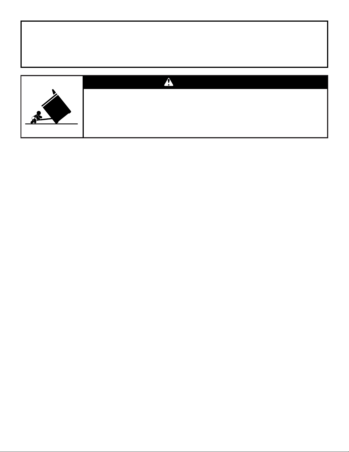
WARNING
Tip Over Hazard
A child or adult can tip the range and be killed.
Connect anti-tip bracket to rear range foot.
Reconnect the anti-tip bracket, if the range is moved.
Failure to follow these instructions can result in death or serious burns to children and adults.
3

INSTALLATION REQUIREMENTS
Tools and Parts
Gather the required tools and parts before starting installation.
Read and follow the instructions provided with any tools listed
here.
Tool s nee ded
■ Tape measure
■ Phillips screwdriver
■ Flat-blade screwdriver
■ ¹⁄₈" flat-blade screwdriver
■ Saber or keyhole saw
■ Level
■ Drill
■ Wrench or pliers
■ Pipe wrench
■ ⁵⁄₁₆" nut driver
■ ¼" nut driver
■ ¹⁵⁄₁₆" combination wrench
■ ¹⁄₈" (3.2 mm) drill bit (for
wood floors)
Parts supplied
Check that all parts are included.
■ LP/Natural Gas Conversion Kit (taped behind access panel)
■ 4 or 5 - Burner caps (depending on model)
■ 2 - Burner grates
■ 2 or 3 - Oven racks (depending on model)
■ Blower motor
■ 2 - vent clamps
■ Marker or pencil
■ Pipe-joint compound
resistant to LP gas
■ ³⁄₁₆" (4.8 mm) carbide-tipped
masonry drill bit (for
concrete/ceramic floors)
■ Noncorrosive leak-detection
solution
For LP/Natural Gas
Conversions
■ ½" combination wrench
■ ¼" (6 mm) nut driver
■ ⁹⁄₃₂" (7 mm) nut driver
■ Masking tape
■ Flexible vent
■ Flow tester card
■ Blower location template
■ 4 - #8 x ¾" screws (for mounting blower motor bracket)
■ 2 - #12 x 1⁵⁄₈" screws (for mounting anti-tip bracket)
■ Anti-tip bracket (taped to package containing literature in
oven cavity)
Anti-tip bracket must be securely mounted to the back wall or
floor. Thickness of flooring may require longer screws to
anchor bracket to subfloor. Longer screws are available from
your local hardware store.
Parts needed
■ One of the following Jenn-Air wall caps:
®
Jenn-Air
Order Part Number A405
Jenn-Air
Order Part Number A406
Jenn-Air
Order Part Number A403
To order, see the “Assistance or Service” section of the Use
and Care Guide.
■ Metal ducting
■ Vent clamps
■ Concrete anchors (for concrete floor mounting)
Check local codes and consult gas supplier. Check existing gas
supply and electrical supply. See “Electrical Requirements” and
“Gas Supply Requirements” sections.
5" (12.7 cm) Round Surface Wall Cap Damper
®
6" (15.2 cm) Round Surface Wall Cap Damper
®
3¼" x 10" (8.3 x 25.4 cm) Surface Wall Cap Damper
4
Location Requirements
IMPORTANT: Observe all governing codes and ordinances. Do
not obstruct flow of combustion and ventilation air.
■ It is the installer’s responsibility to comply with installation
clearances specified on the gas information plate. The gas
information plate is located on the right-hand side of the
bottom oven frame.
■ The range should be located for convenient use in the
kitchen.
■ Recessed installations must provide complete enclosure of
the sides and rear of the range.
■ To eliminate the risk of burns or fire by reaching over heated
surface units, cabinet storage space located above the
surface units should be avoided. If cabinet storage is to be
provided, the risk can be reduced by installing a range hood
or microwave hood combination that projects horizontally a
minimum of 5" (12.7 cm) beyond the bottom of the cabinets.
■ All openings in the wall or floor where range is to be installed
must be sealed.
■ Cabinet opening dimensions that are shown must be used.
Given dimensions are minimum clearances.
■ The floor anti-tip bracket must be installed. To install the anti-
tip bracket shipped with the range, see “Install Anti-Tip
Bracket” section.
■ Grounded electrical supply is required. See “Electrical
Requirements” section.
■ Proper gas supply connection must be available. See “Gas
Supply Requirements” section.
■ Contact a qualified floor covering installer to check that the
floor covering can withstand at least 200°F (93°C).
■ Use an insulated pad or ¼" (0.64 cm) plywood under range if
installing range over carpeting.
IMPORTANT: To avoid damage to your cabinets, check with your
builder or cabinet supplier to make sure that the materials used
will not discolor, delaminate or sustain other damage. This oven
has been designed in accordance with the requirements of UL
and CSA International and complies with the maximum allowable
wood cabinet temperatures of 194°F (90°C).
Mobile Home - Additional Installation Requirements
The installation of this range must conform to the Manufactured
Home Construction and Safety Standard, Title 24 CFR, Part 3280
(formerly the Federal Standard for Mobile Home Construction
and Safety, Title 24, HUD Part 280). When such standard is not
applicable, use the Standard for Manufactured Home
Installations, ANSI A225.1/NFPA 501A or with local codes.
In Canada, the installation of this range must conform with the
current standards CAN/CSA-A240-latest edition, or with local
codes.
Mobile home installations require:
■ When this range is installed in a mobile home, it must be
secured to the floor during transit. Any method of securing
the range is adequate as long as it conforms to the standards
listed above.
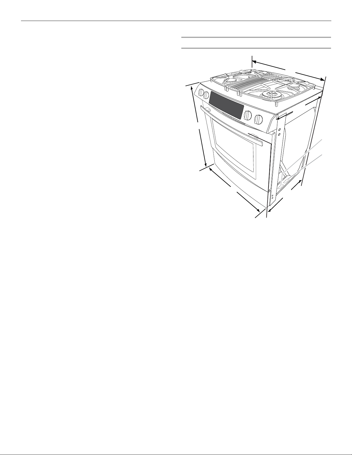
Product Dimensions
A
B
G
F
A. 30³⁄₄" (78.1 cm)
B. 23½" (59.7 cm) countertop
notch to rear of cooktop
C. Gas information plate (located
on the right-hand side of the
bottom oven frame)
D. Model/serial number plate
(located on the right-hand
side of the bottom oven
frame)
E. 29¹⁄₁₆" (73.8 cm) from handle
to back of range**
F. 2 9 ⁷⁄₈" (75.9 cm)
G. 35³⁄₄" (90.8 cm) height to
underside of cooktop edge
with leveling legs screwed all
the way in*
*Range can be raised approximately 1" (2.5 cm) by adjusting
the leveling legs.
**When installed in a 24" (61.0 cm) base cabinet with
25" (63.5 cm) countertop; front of oven door protrudes
2¹⁄₂" (6.4 cm) beyond 24" (61.0 cm) base cabinet.
E
C
C
D
D
5
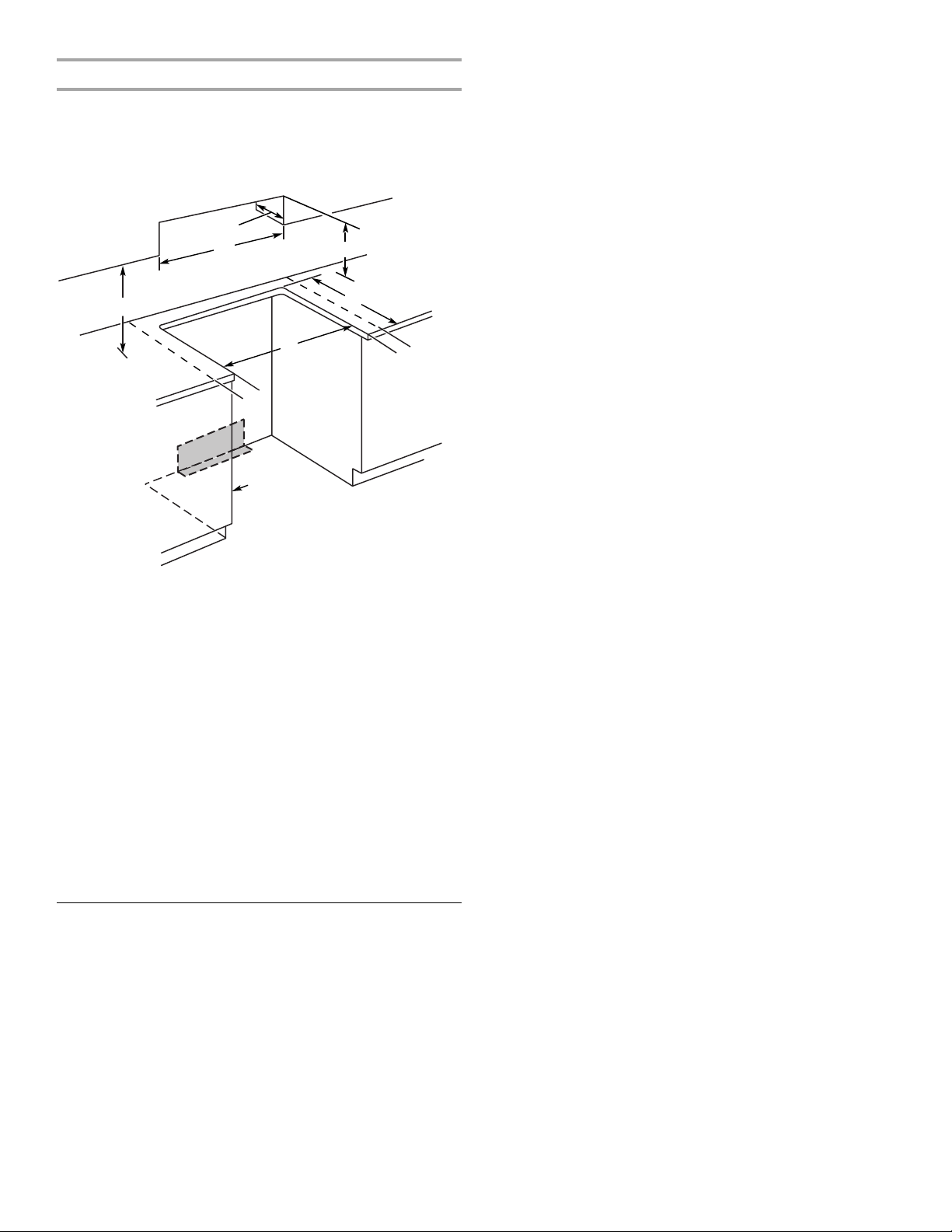
Cabinet Dimensions
Cabinet opening dimensions shown are for 25" (64.0 cm)
countertop depth, 24" (61.0 cm) base cabinet depth and
36" (91.4 cm) countertop height.
Range may be installed with zero clearance to combustible
construction at the rear and on the sides below the cooktop.
A
B
H
E
C
D
I
I
F
G
A. 13" (33.0 cm) upper cabinet depth
B. 30" (76.2 cm) min. opening width
C. For minimum clearance to the top of the cooktop, see NOTE.
D. 23¹⁄₄" (59.1 cm) opening depth
E. 30" (76.2 cm) min. opening width
F. Electrical and gas supply - 5½" (14.0 cm) min. from either cabinet,
10" (25.4 cm) max. from floor. Nothing located in shaded area can
extend more than 2¼" (5.7 cm) from back wall or range will not slide
all the way back. Grounded outlet must be flush mounted.
G. Cabinet door or hinge should not extend into cutout.
H. 18" (45.7 cm)
I. 3" (7.6 cm) min. clearance from both sides of the range to the side
wall or other combustible material.
NOTE: 24" (61.0 cm) minimum when bottom of wood or metal
cabinet is shielded by not less than ¹⁄₄" (0.64 cm) flame retardant
millboard covered with not less than No. 28 MSG sheet steel,
0.015" (0.4 mm) stainless steel, 0.024" (0.6 mm) aluminum or
0.020" (0.5 mm) copper.
30" (76.2 cm) minimum clearance between the top of the cooking
platform and the bottom of an uncovered wood or metal cabinet.
Venting Requirements
IMPORTANT: This range must be exhausted outdoors. See
“Venting Methods” section.
■ Do not terminate the vent system in an attic or other enclosed
area.
■ Use a Jenn-Air vent cap.
■ Vent system must terminate to the outside.
■ Use only a 6" (15.2 cm) round metal vent or a 3¼ x 10"
(8.3 cm x 25.4 cm) rectangular vent.
■ Rigid metal vent is recommended. For best performance, do
not use plastic or metal foil vent.
■ Before making cutouts, make sure there is proper clearance
within the wall or floor for the exhaust vent.
■ Do not cut a joist or stud unless absolutely necessary. If a
joist or stud must be cut, then a supporting frame must be
constructed.
■ The size of the vent should be uniform.
■ The vent system must have a damper. If roof or wall cap has a
damper, do not use damper supplied with the range hood.
■ Use vent clamps to seal all joints in the vent system.
■ Use caulking to seal exterior wall or roof opening around the
cap.
■ Determine which venting method is best for your application.
For Best Performance:
■ Use 26-gauge minimum galvanized or 25-gauge minimum
aluminum metal vent. Poor quality pipe fittings can reduce
airflow. For external venting, flexible metal vent is not
recommended.
NOTE: Local codes may require a heavier gauge material.
■ Metal duct may be reduced to 30-gauge galvanized steel or
26-gauge aluminized steel if allowed by local codes. This
reduction is based on information in the International
Residential Codes Section M1601.1 (2006 edition).
■ Do not install 2 elbows together.
■ Use no more than three 90° elbows.
■ If an elbow is used, install it as far away as possible from the
hood’s vent motor exhaust opening.
■ Make sure there is a minimum of 18" (45.7 cm) of straight
vent between the elbows if more than one elbow is used.
■ Elbows too close together can cause excess turbulence that
reduces airflow.
■ Do not use a 5" (12.7 cm) elbow in a 6" (15.2 cm) or 3¹⁄₄" x 10"
(8.3 x 25.4 cm) system.
■ Do not reduce to a 5" (12.7 cm) system after using a 6"
(15.2 cm) or 3¹⁄₄" x 10" (8.3 x 25.4 cm) fittings.
■ Avoid forming handmade crimps. Handmade crimps may
restrict airflow.
■ Use a Jenn-Air vent cap for proper performance. If an
alternate wall or roof cap is used, be certain the cap size is
not reduced and that it has a backdraft damper.
■ Use vent clamps to seal all joints in the vent system.
■ Use caulking to seal exterior wall or roof opening around the
cap.
The length of vent system and number of elbows should be kept
to a minimum to provide efficient performance.
The maximum equivalent length of the vent system is 60 ft
(18.3 m). For altitudes above 4,500 ft (1272 m), reduce
recommended vent run by 20% for best performance.
Cold Weather Installations
An additional backdraft damper should be installed to minimize
backward cold air flow and a thermal break installed to minimize
conduction of outside temperatures as part of the vent system.
The damper should be on the cold air side of the thermal break.
Makeup Air
Local building codes may require the use of makeup air systems
when using ventilation systems greater than specified CFM of air
movement. The specified CFM varies from locale to locale.
Consult your HVAC professional for specific requirements in your
area.
6
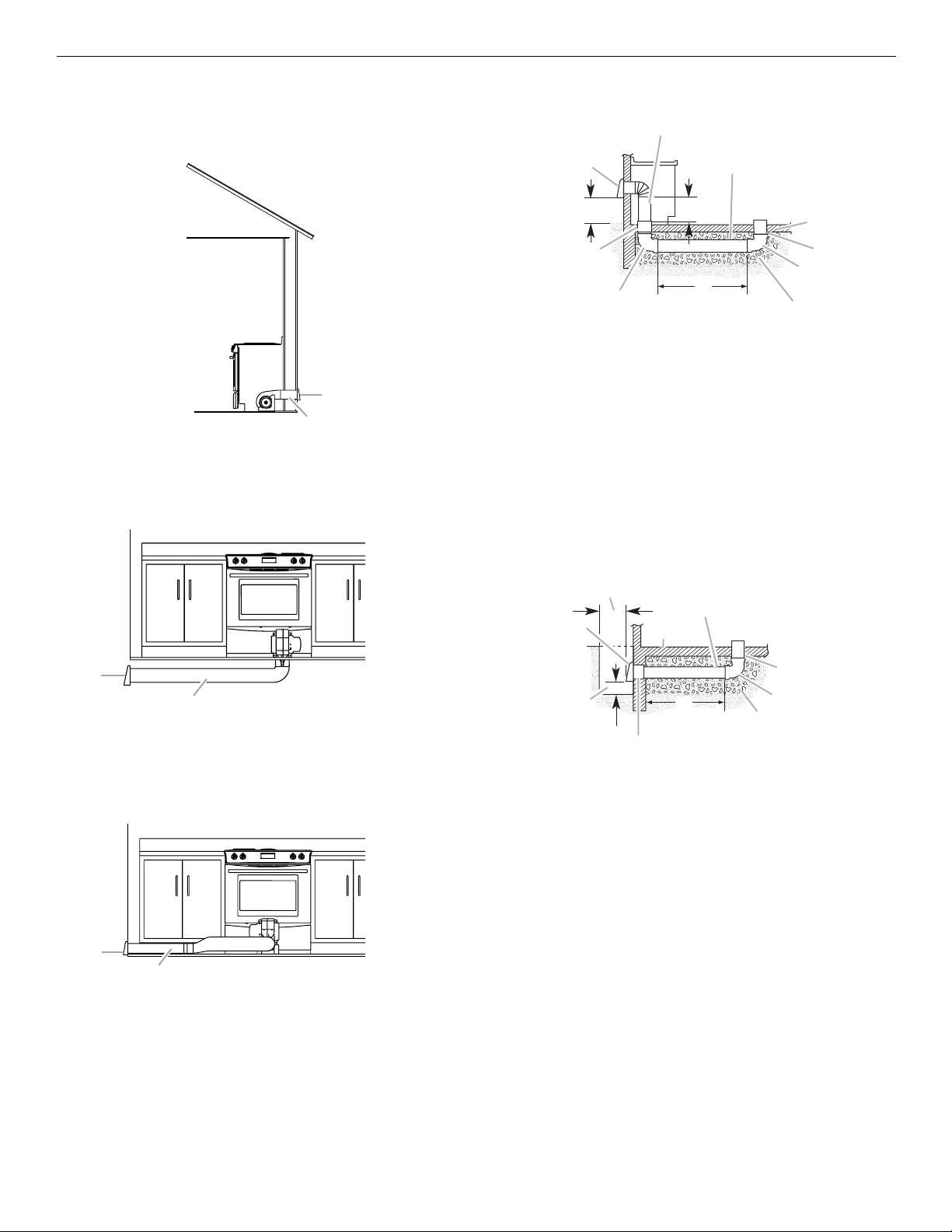
Ven ting M eth ods
A
F
Common venting methods are shown for a downdraft range. The
downdraft range may be vented through the wall or floor.
Wall Venting
Concrete Slab Installations - Exhaust Through Wall
B
A
D
A. Wall cap
B. 6" (15.2 cm) round roof venting
Floor Venting
Venting Between Floor Joists
L
K
J
C
I
E
G
H
A. Wall cap
B. 6" (15.2 cm) round metal vent
C. 16" (40.6 cm) maximum
D. 6" (15.2 cm) round PVC sewer pipe
E. Concrete slab
B
F. 6" (15.2 cm) round PVC sewer pipe
G. 6" (15.2 cm) round 90° PVC sewer pipe elbow
H. Tightly pack gravel or sand completely around pipe.
I. 30 ft (9.1 m) max.
J. 6" (15.2 cm) round 90° PVC sewer pipe elbow
K. 6" (15.2 cm) round PVC coupling
L. 12" (30.5 cm) minimum
Concrete Slab Installations Exhaust Through Window Well
IMPORTANT: Window well installation for electric models only.
B
D
A
C
A
B
A. Wall cap
B. 6" (15.2 cm) round roof venting
Side Venting
Venting Behind Cabinet Kickplate
A
B
A. Wall cap
B. 6" (15.2 cm) round roof venting
E
K
J
A. Wall cap
B. 12" (30.5 cm) minimum
C. Concrete slab
D. 6" (15.2 cm) round PVC sewer pipe
E. 6" (15.2 cm) round PVC sewer pipe
F. 6" (15.2 cm) round 90° PVC sewer pipe elbow
G. Tightly pack gravel or sand completely around pipe.
H. 42 ft (12.8 m) max.
I. 6" (15.2 cm) round PVC coupling
J. 6" (15.2 cm) minimum
K. Window well
H
I
F
G
7
Calculating Vent System Length
IMPORTANT: This range is rated at 60 ft (18.3 m) of straight duct.
Low range is up to 30 ft (9.1 m); high range is 31 ft (9.4 m) to
60 ft (18.3 m).
If equivalent duct length exceeds 30 ft (18.3 m), the blower must
be converted to high range.
■ Do not convert to high range for shorter lengths. This will
cause excessive noise, conditioned air loss and affect the
flame pattern on gas ranges.
■ To convert blower for high range installations, see the
“Install Downdraft System” section.
To calculate the length of the system you need, add the
equivalent feet (meters) for each vent piece used in the system.
Vent Piece 6" (15.2 cm) Round
45° elbow 2.5 ft
(0.8 m)
90° elbow 5.0 ft
6" (15.2 cm)
wall cap
3¹⁄₄" x 10" (8.3 cm x 25.4 cm)
to 6" (15.2 cm) transition
6" (15.2 cm) to 3¹⁄₄" x 10"
(8.3 cm x 25.4 cm) transition
3¹⁄₄" x 10" (8.3 cm x 25.4 cm)
to 6" (15.2 cm) 90° elbow
transition
6" (15.2 cm) to 3¹⁄₄" x 10"
(8.3 cm x 25.4 cm) 90° elbow
transition
(1.5 m)
0.0 ft
(0.0 m)
4.5 ft
(1.4 m)
1 ft
(0.3 m)
5.0 ft
(1.5 m)
5.0 ft
(1.5 m)
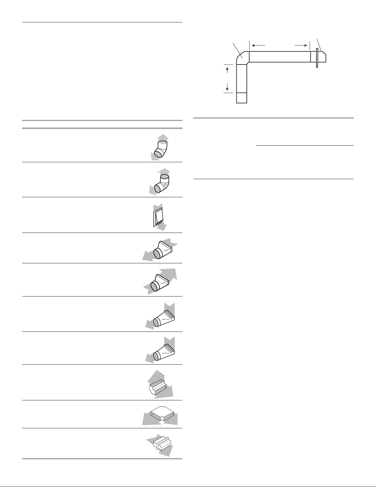
Example vent system
90˚ elbow
6 ft (1.8 m)
2 ft
(0.6 m)
Maximum length = 60 ft (18.3 m)
1- 90° elbow = 5 ft (1.5 m)
8 ft (2.4 m) straight = 8 ft (2.4 m)
1 - wall cap = 0 ft (0 m)
System length = 13 ft (3.9 m)
NOTE: For external venting, flexible vent is not recommended.
Flexible vent creates back pressure and air turbulence that
greatly reduce performance.
wall cap
Electrical Requirements
IMPORTANT: The range must be electrically grounded in
accordance with local codes and ordinances, or in the absence
of local codes, with the National Electrical Code, ANSI/NFPA 70
or Canadian Electrical Code, CSA C22.1.
If codes permit and a separate ground wire is used, it is
recommended that a qualified electrical installer determine that
the ground path is adequate.
A copy of the above code standards can be obtained from:
National Fire Protection Association
One Batterymarch Park
Quincy, MA 02269
CSA International
8501 East Pleasant Valley Road
Cleveland, OH 44131-5575
■ A 120 volt, 60 Hz., AC only, 15-amp fused, electrical circuit is
required. A time-delay fuse or circuit breaker is also
recommended. It is recommended that a separate circuit
serving only this range be provided.
■ Electronic ignition systems operate within wide voltage limits,
but proper grounding and polarity are necessary. Check that
the outlet provides 120-volt power and is correctly grounded.
■ The wiring diagram is located on the back of the access
panel in a clear plastic bag.
3¹⁄₄" x 10" (8.3 cm x 25.4 cm)
90° elbow
3¹⁄₄" x 10" (8.3 cm x 25.4 cm)
flat elbow
3¹⁄₄" x 10" (8.3 cm x 25.4 cm)
wall cap
8
5.0 ft
(1.5 m)
12.0 ft
(3.7 m)
0.0 ft
(0.0 m)
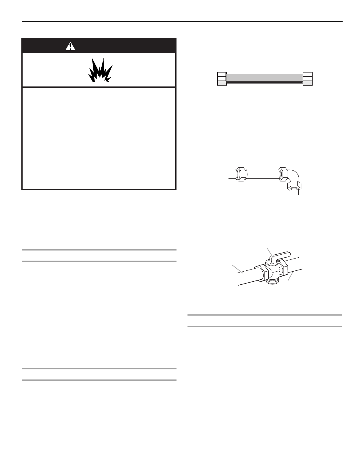
WARNING
Gas Supply Requirements
Flexible metal appliance connector:
■ If local codes permit, a new CSA design-certified,
4 to 5 ft (122 to 152.4 cm) long, ½" (1.3 cm) or
¾" (1.9 cm) I.D., flexible metal appliance connector may
be used for connecting range to the gas supply line.
Explosion Hazard
Use a new CSA International approved gas supply line.
Install a shut-off valve.
Securely tighten all gas connections.
If connected to LP, have a qualified person make sure
gas pressure does not exceed 14" (36 cm) water
column.
Examples of a qualified person include:
licensed heating personnel,
authorized gas company personnel, and
authorized service personnel.
Failure to do so can result in death, explosion, or fire.
Observe all governing codes and ordinances.
IMPORTANT: This installation must conform with all local codes
and ordinances. In the absence of local codes, installation must
conform with American National Standard, National Fuel Gas
Code ANSI Z223.1 - latest edition or CAN/CGA B149 - latest
edition.
IMPORTANT: Leak testing of the range must be conducted
according to the manufacturer’s instructions.
Type of G a s
Natural gas:
This range is design-certified by CSA International for use with
Natural gas or, after proper conversion, for use with LP gas.
■ This range is factory set for use with Natural gas. See “Gas
Conversions” section. The gas information plate located on
the right-hand side bottom frame has information on the
types of gas that can be used. If the types of gas listed do not
include the type of gas available, check with the local gas
supplier.
LP gas conversion:
Conversion must be done by a qualified service technician.
No attempt shall be made to convert the appliance from the gas
specified on the gas information plate for use with a different gas
without consulting the serving gas supplier. See “Gas
Conversions” section.
Gas Supply Line
■ Provide a gas supply line of ¾" (1.9 cm) rigid pipe to the
range location. A smaller size pipe on longer runs may result
in insufficient gas supply. With LP gas, piping or tubing size
can be ½" (1.3 cm) minimum. Usually, LP gas suppliers
determine the size and materials used in the system.
NOTE: Pipe-joint compounds that resist the action of LP gas
must be used. Do not use TEFLON
®†
tape.
■ A ½" (1.3 cm) male pipe thread is needed for connection
to the female pipe threads of the inlet to the appliance
pressure regulator.
■ Do not kink or damage the flexible metal tubing when
moving the range.
Rigid pipe connection:
The rigid pipe connection requires a combination of pipe
fittings to obtain an in-line connection to the range. The rigid
pipe must be level with the range connection. All strains must
be removed from the supply and fuel lines so range will be
level and in line.
■ Must include a shutoff valve:
The supply line must be equipped with a manual shutoff
valve. This valve should be located in the same room but
external to the range opening, such as an adjacent cabinet. It
should be in a location that allows ease of opening and
closing. Do not block access to shutoff valve. The valve is for
turning on or shutting off gas to the range.
B
A
C
A. Gas supply line
B. Shutoff valve “open” position
C. To range
Gas Pressure Regulator
The gas pressure regulator supplied with this range must be
used. The inlet pressure to the regulator should be as follows for
proper operation:
Natural gas:
Minimum pressure: 5" WCP
Maximum pressure: 14" WCP
LP gas:
Minimum pressure: 11" WCP
Maximum pressure: 14" WCP
Contact local gas supplier if you are not sure about the inlet
pressure.
†®TEFLON is a registered trademark of E.I. Du Pont De Nemours and Company.
9
Burner Input Requirements
Input ratings shown on the gas information plate are for
elevations up to 2,000 ft (609.6 m).
For elevations above 2,000 ft (609.6 m), ratings are reduced at a
rate of 4% for each 1,000 ft (304.8 m) above sea level (not
applicable for Canada).
Gas Supply Pressure Testing
Gas supply pressure for testing regulator must be at least
1" water column pressure above the manifold pressure shown on
the gas information plate.
Line pressure testing above ½ psi gauge (14" WCP)
The range and its individual shutoff valve must be disconnected
from the gas supply piping system during any pressure testing of
that system at test pressures in excess of ½ psi (3.5 kPa).
Line pressure testing at ½ psi gauge (14" WCP) or lower
The range must be isolated from the gas supply piping system by
closing its individual manual shutoff valve during any pressure
testing of the gas supply piping system at test pressures equal to
or less than ½ psi (3.5 kPa).
Countertop Preparation
(for Slide-in Ranges Only)
The cooktop sides of the slide-in range fit over the cutout edge of
your countertop.
If you have a square finish (flat) countertop and the opening width
is 30" (76.2 cm), no countertop preparation is required.
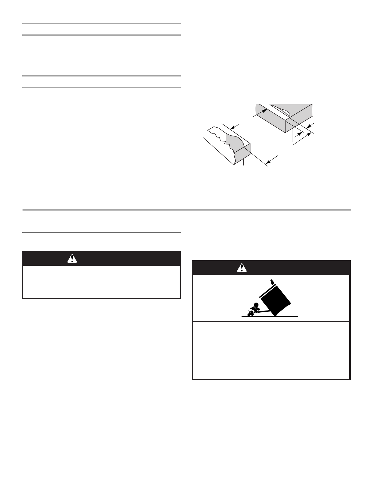
Formed front-edged countertops must have molded edge
shaved flat ³⁄₈" (1.0 cm) from each front corner of opening.
Tile countertops may need trim cut back ³⁄₈" (1.0 cm) from each
front corner and/or rounded edge flattened.
30"
(76.2 cm)
30 ¾"
(78.1 cm)
If countertop opening width is greater than 30" (76.2 cm), adjust
the ³⁄₈" (1.0 cm) dimension.
Countertop must be level. Place level on countertop, first side to
side, then front to back. If countertop is not level, range will not
be level. Range must be level for satisfactory baking conditions.
³⁄₈"
(1.0 cm)
INSTALLATION INSTRUCTIONS
Unpack Range
WARNING
Excessive Weight Hazard
Use two or more people to move and install range.
Failure to do so can result in back or other injury.
1. Remove shipping materials, tape and film from the range.
Keep cardboard bottom under range.
2. Remove oven racks and parts package from inside oven.
3. To remove cardboard bottom, place range on its back, take
4 cardboard corners from the carton. Stack one cardboard
corner on top of another. Repeat with the other 2 corners.
Place them lengthwise on the floor behind the range to
support the range when it is laid on its back.
4. Using 2 or more people, firmly grasp the range and gently lay
it on its back on the cardboard corners.
5. Pull cardboard bottom firmly to remove.
6. Use an adjustable wrench to loosen the leveling legs.
7. Place cardboard or hardboard in front of range. Using 2 or
more people, stand range back up onto cardboard or
hardboard.
Adjust Leveling Legs
1. If range height adjustment is necessary, use a wrench or
pliers to loosen the 4 leveling legs.
This may be done with the range on its back or with the range
supported on 2 legs after the range has been placed back to
a standing position.
NOTE: To place range back up into a standing position, put a
sheet of cardboard or hardboard in front of range. Using 2 or
more people, stand range back up onto the cardboard or
hardboard.
WARNING
Tip Over Hazard
A child or adult can tip the range and be killed.
Connect anti-tip bracket to rear range foot.
Reconnect the anti-tip bracket, if the range is moved.
Failure to follow these instructions can result in death
or serious burns to children and adults.
2. Adjust the leveling legs to the correct height. Leveling legs
can be loosened to add up to a maximum of 1" (2.5 cm). A
minimum of ³⁄₁₆" (5 mm) is needed to engage the anti-tip
bracket.
NOTE: If height adjustment is made when range is standing,
tilt the range back to adjust the front legs, then tilt forward to
adjust the rear legs.
10
3. When the range is at the correct height, check that there is
B
adequate clearance under the range for the anti-tip bracket.
Before sliding range into its final location, check that the antitip bracket will slide under the range and onto the rear
leveling leg prior to anti-tip bracket installation.
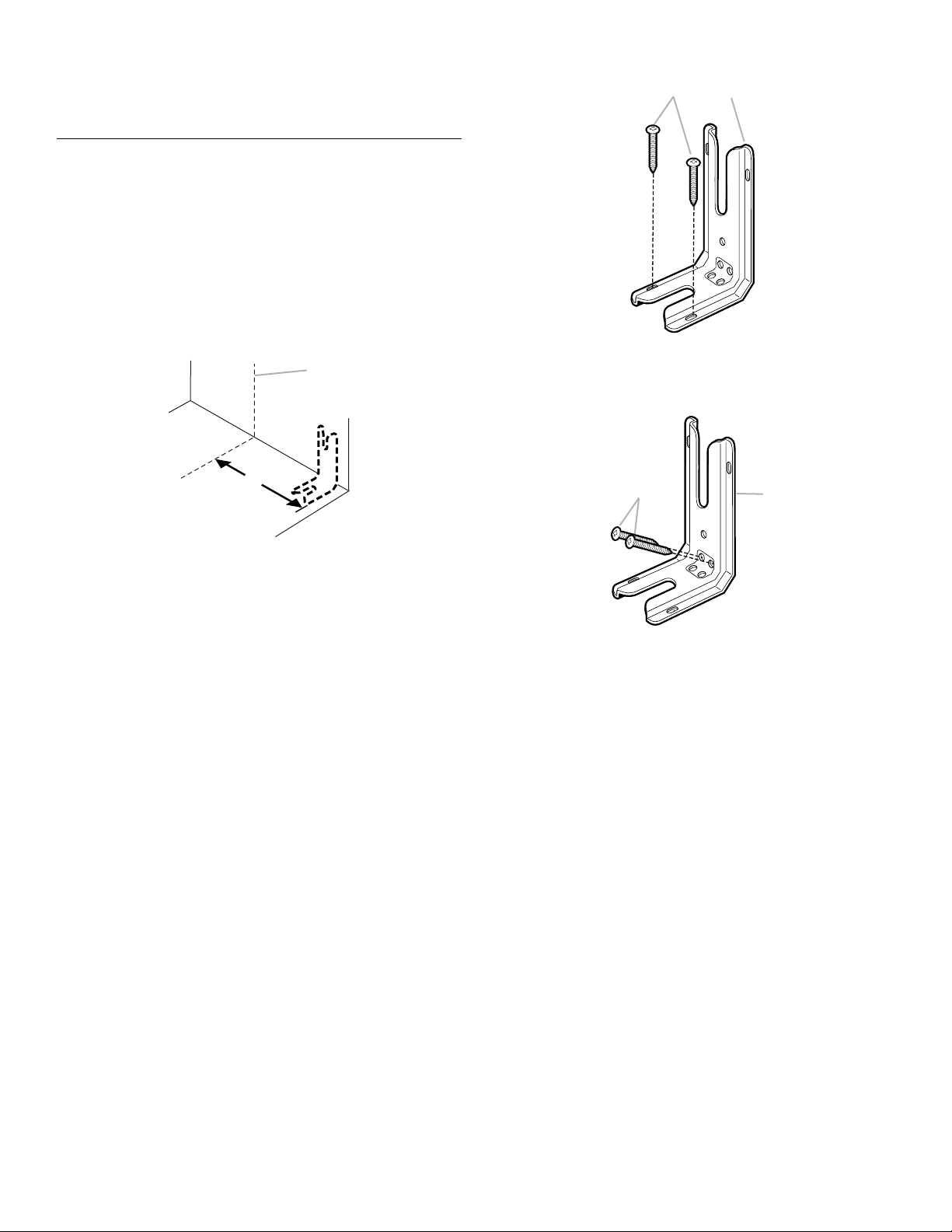
Install Anti-Tip Bracket
1. Remove the anti-tip bracket that is taped to the package
containing literature.
2. Determine which mounting method to use: floor or wall.
If you have a stone or masonry floor you can use the wall
mounting method.
3. Determine and mark centerline of the cutout space. The
mounting bracket can be installed on either the left side or
right side of the cutout. Position mounting bracket in cutout
so that right (or left) edge of the bracket is 14¹⁄₄" (36.2 cm)
from centerline, as shown.
A
Floor Mounting
Wall Mounting
A
A. #12 x 1⁵⁄₈" screws
B. Anti-tip bracket
B
B
A. Centerline
B. 14¹⁄₄" (36.2 cm)
4. Drill two ¹⁄₈" (3.0 mm) holes that correspond to the bracket
holes of the determined mounting method. See below.
A
A. #12 x 1⁵⁄₈" screws
B. Anti-tip bracket
5. Using the Phillips screwdriver, mount anti-tip bracket to the
wall or floor with the two #12 x 1⁵⁄₈" screws provided.
11
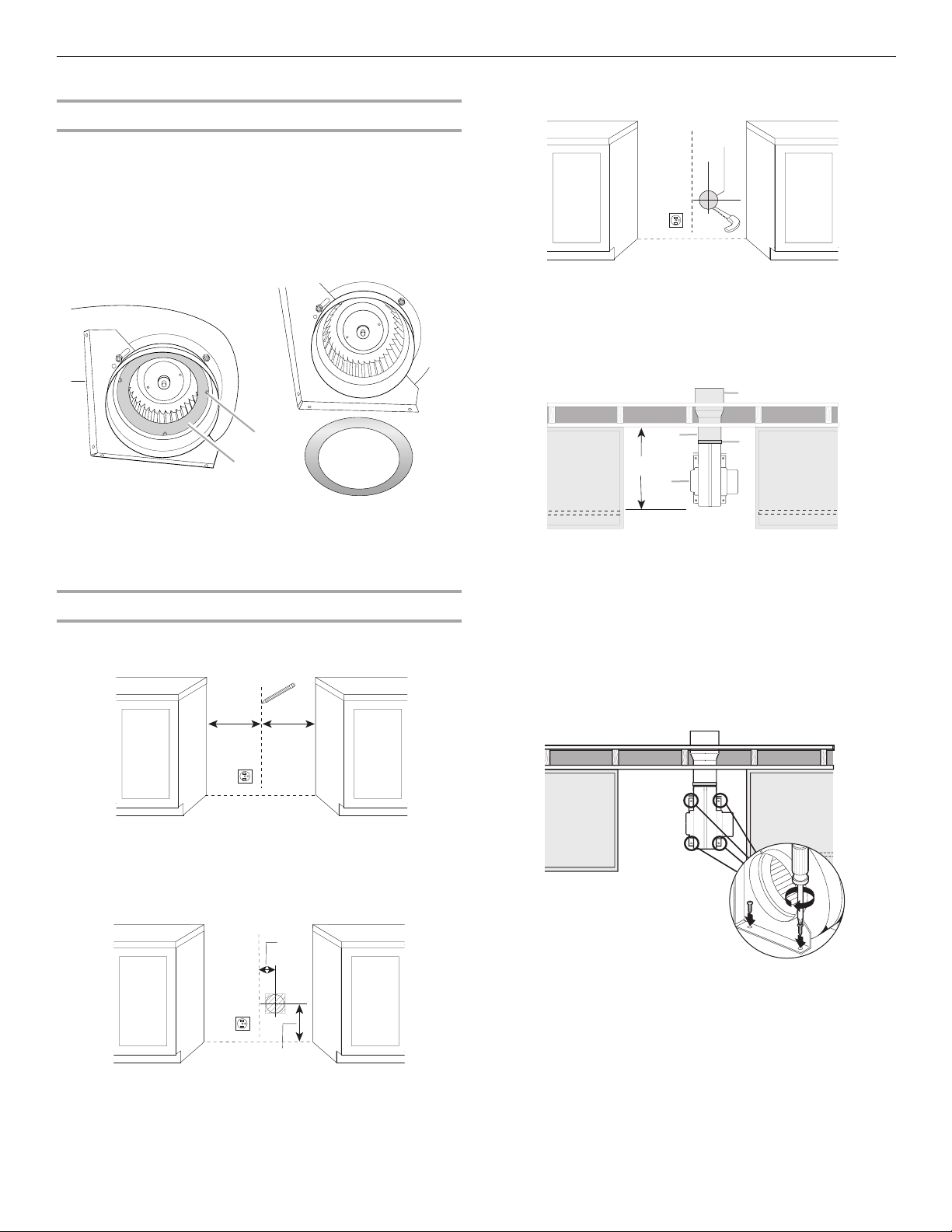
Install Downdraft System
Determine Equivalent Length of Vent System
This range is equipped with a dual range blower. It is shipped
from the factory for Low Range installations. If vent system
equivalent length exceeds 30 ft (9.1 m), the downdraft blower
motor must be converted to High Range for best performance.
See “Calculating Vent System Length.”
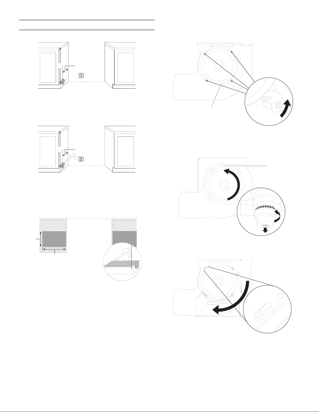
To Con v ert:
Gently remove the spring loaded Restricter Ring from the blower
inlet by pressing on one of the 3 springs.
3. Draw and cut a 6¼" (15.8 cm) diameter hole.
A
A. 6¼" (15.8 cm)
4. Position blower motor in cabinet opening. Connect vent
system to blower motor outlet using a vent clamp.
Top View
E
B
A
A. Restricter ring
B. Spring
Determine which venting method to use: floor, rear wall, or left
side venting. Go to the section for your type of venting.
Rear Wall Venting
1. Mark the wall at the center of the cabinet opening.
2. Check for obstructions before marking the vent hole location.
Mark a horizontal line 8³⁄₁₆" (20.8 cm) from the floor. Mark a
vertical line up to a maximum of 2¼" (7.9 cm) from the right
side of the cabinet centerline.
C
D
A
B
A. 18¾" (47.6 cm) maximum from back
wall forward into cabinet opening
B. Inlet
C. Vent system
D. Vent clamp
E. Wall vent
5. Mount blower motor to the floor with 4 - #8 x ¾" hex head
screws provided.
Top View
12
A
B
A. Maximum 2¼" (7.9 cm) from
the right of center
B. 8³⁄₁₆" (20.8 cm) from floor
6. Go to the “Make Gas Connection” section.
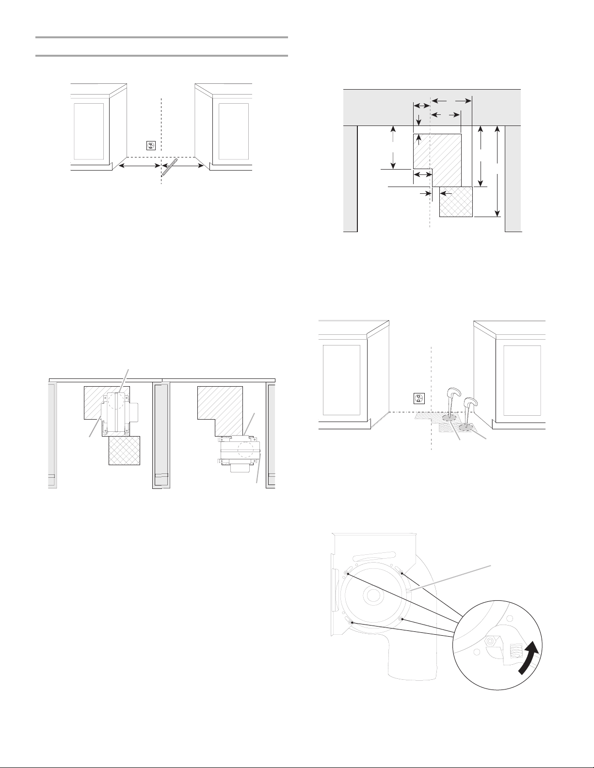
Floor Venting
1. Mark the floor at the center of the cabinet opening.
NOTE: If the template is misplaced, the following
measurements can be used to determine the vent hole
location.
Top View
2. Position template on floor by matching the centerline of the
template to the centerline drawn on the floor and place
template 2¼" (5.7 cm) from the back wall.
3. Determine the correct position for the vent hole, depending
on obstructions (joists) in the floor.
The hole can be cut anywhere within the boundaries of either
hatched area.
Option 1: If using the back hatched area (bigger one), the
blower inlet must face the left side as shown on the template.
Option 2: If using the front hatched area (smaller one), the
blower inlet must face the back.
Top View
Option 1 Option 2
B
B
C
D
A
E
F
I
H
A. 9" (22.8 cm)
B. 3¹⁄₈" (7.9 cm)
C. 8³⁄₈" (21.3 cm)
D. 6³⁄₈" (16.2 cm)
E. 2¼" (5.7 cm)
F. 12½" (31.7 cm)
G. 18¾" (47.6 cm)
H. 1½" (3.8 cm)
I. 3½" (8.9 cm)
4. Draw and cut a 6¼" (15.8 cm) diameter hole.
G
A
A
A. Option 1
B. Option 2
B
5. Remove the 4 locknuts on the blower side of the motor and
B
A
remove the bracket.
A. Inlet from range
B. Exhaust outlet
View from Motor Side of Blower
A
A. Electrical connector
13
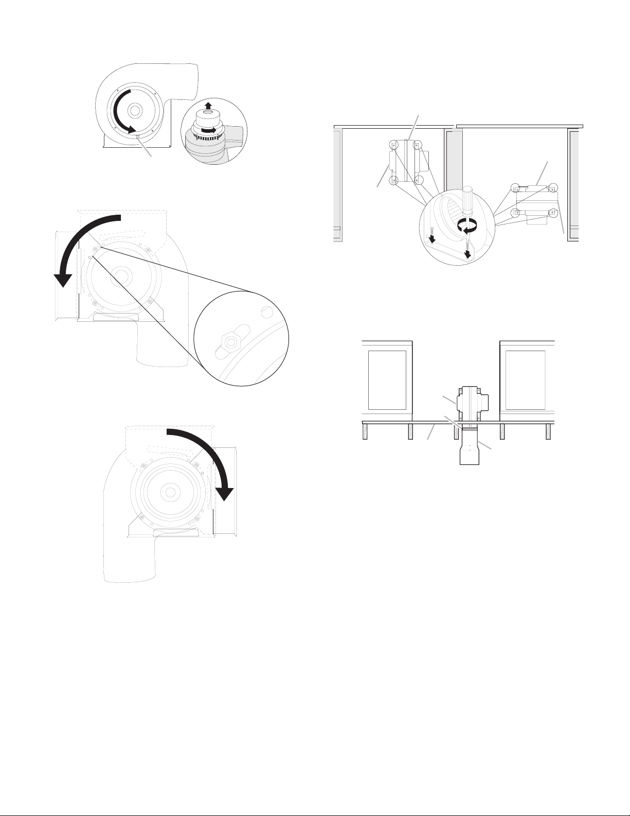
6. Lift and rotate the motor 90° to reposition the electrical
connection.
9. Position blower motor in cabinet opening and mount blower
motor to the floor.
Top View
Option 1 Option 2
B
A
A. Electrical connector
7. Rotate bracket 90° and secure with 4 locknuts.
8. Remove the bracket from the other side of the blower motor,
rotate 90° and secure with 4 locknuts.
A
A
B
A. Inlet from range
B. Exhaust outlet
10. Connect vent system to blower motor outlet (option 1 shown)
with 4 - #8 x ¾" hex head screws provided.
A
B
C
D
A. Inlet
B. Vent clamp
C. Floor
D. Vent system
11. Go to the “Make Gas Connection” section.
14
Left Side Venting
1. Mark cabinet side for left side vent hole location.
4. Remove 4 locknuts on the motor side of the blower and
remove the bracket.
View from Motor Side of Blower
A
A. 31³⁄₁₆" (79.2 cm) from top of cabinet
B. 18" (45.7 cm) from back wall
B
2. Mark and cut a 5½" (13.9 cm) diameter hole in the cabinet
side.
A
B
A. 5½" (13.9 cm) diameter hole
3. Mark and cut a 14" x 11" (35.6 x 27.9 cm) opening in the floor
of the cabinet.
Top View
A
A. Electrical connector
5. Lift and rotate the motor 180° to reposition the electrical
connection.
A
A
A. Electrical connector
6. Rotate bracket 90° and secure with 4 locknuts.
B
A. 11" (27.9 cm) from front of cabinet
B. 14" (35.6 cm) from left side of cabinet
15

7. Remove the bracket from the other side of the blower motor,
rotate 90° and secure with 4 locknuts.
8. Mount blower motor to floor using 4 - #8 x ¾" hex head
screws provided.
NOTE: Vent system will be connected after range has been
moved into its final location. “See Connect Range to
Downdraft System” in the “Installation Instructions” section.
Top View
B
A
C
Make Gas Connection
WARNING
Explosion Hazard
Use a new CSA International approved gas supply line.
Install a shut-off valve.
Securely tighten all gas connections.
If connected to LP, have a qualified person make sure
gas pressure does not exceed 14" (36 cm) water
column.
Examples of a qualified person include:
licensed heating personnel,
authorized gas company personnel, and
authorized service personnel.
Failure to do so can result in death, explosion, or fire.
A. 2⁷⁄₈" (7.3 cm) from back wall
to edge of bracket
B. Mounting bracket
C. Blower
9. Go to the “Make Gas Connection” section.
Typical flexible connection
1. Open access panel by grasping sides and pulling upward,
lifting out.
2. Locate gas pressure regulator behind access panel.
A
A. Gas pressure regulator
3. Apply pipe-joint compound made for use with LP gas to the
smaller thread ends of the flexible connector adapters (see B
and G in the following illustration).
4. Attach one adapter to the gas pressure regulator and the
other adapter to the gas shutoff valve. Tighten both adapters.
16
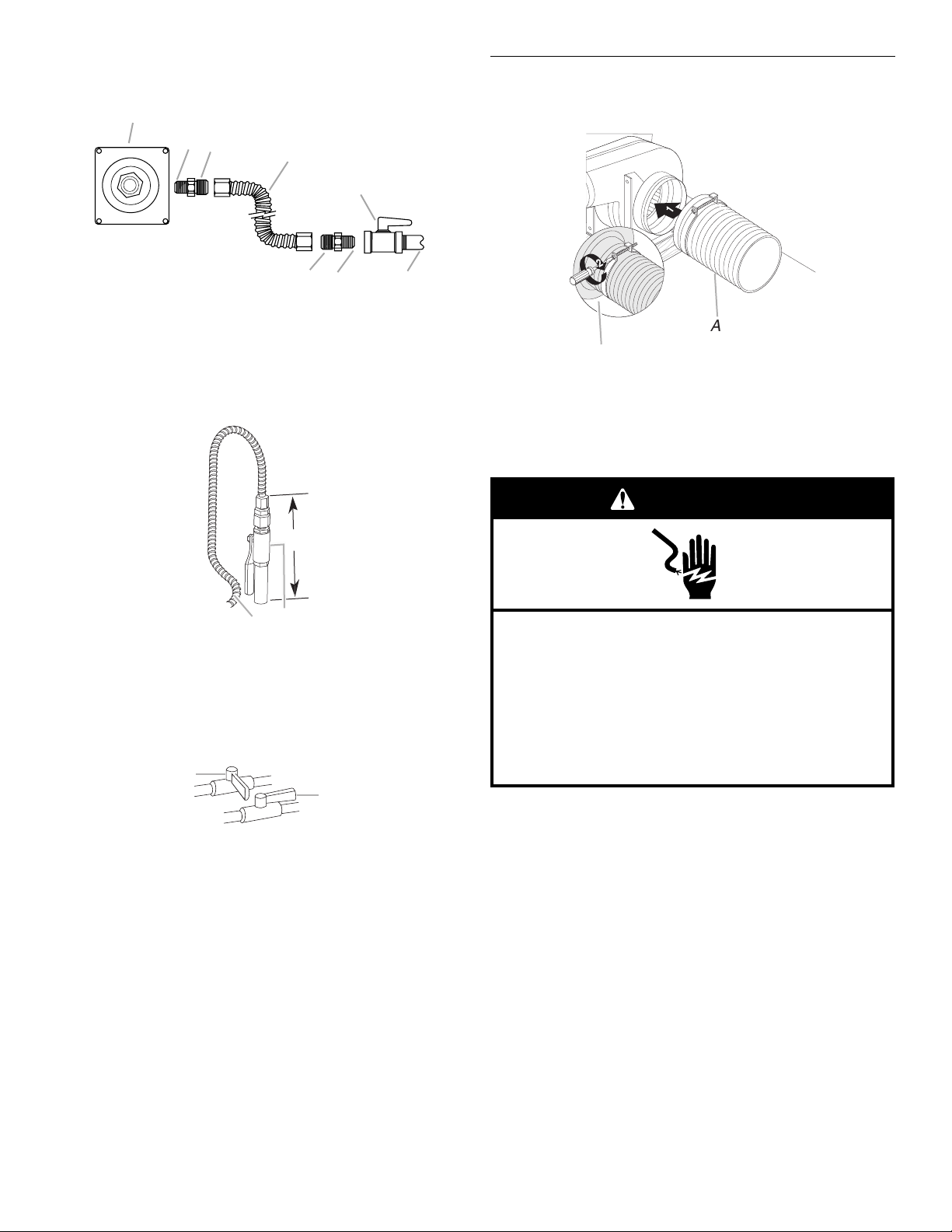
5. Use a ¹⁵⁄₁₆" combination wrench and an adjustable wrench to
attach the flexible connector to the adapters. Check that
connector is not kinked.
A
B
C
D
E
Connect Range to Downdraft System
1. Attach flexible vent (provided) to the blower motor inlet using
a vent clamp.
1
1
A. Gas pressure regulator
B. Use pipe-joint compound.
C. Adapter (must have ½" male
pipe thread)
D. Flexible connector
H
E. Manual gas shutoff valve
F. ½" or ¾" g a s p i p e
G. Use pipe-joint compound.
H. Adapter
FG
6. Gas supply pipe must not be more than 10" (25.4 cm) above
the floor.
C
A
B
A. Flexible connector
B. Manual shutoff valve
C. 10" (25.4 cm) max. straight pipe
Complete Connection
1. Open the manual shutoff valve in the gas supply line. The
valve is open when the handle is parallel to the gas pipe.
A
B
2
A
B
A. Inlet flexible vent
B. Vent clamp
2. Check countertop height to allow range top to clear
countertop. Adjusting leveling legs if necessary.
3. Move range close to cabinet opening.
WARNING
Electrical Shock Hazard
Plug into a grounded 3 prong outlet.
Do not remove ground prong.
Do not use an adapter.
Do not use an extension cord.
Failure to follow these instructions can result in death,
fire, or electrical shock.
4. Plug into a grounded 3 prong outlet.
A. Closed valve
B. Open valve
2. Test all connections by brushing on an approved
noncorrosive leak-detection solution. If bubbles appear, a
leak is indicated. Correct any leak found.
3. Remove cooktop burner caps and grates from package
containing parts. Align recess in burner caps with pins in
burner base. Burner caps should be level when properly
positioned. If burner caps are not properly positioned,
surface burners will not light. Place burner grates over
burners and caps.
17
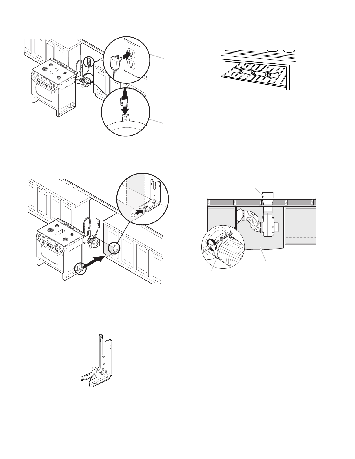
5. Plug range electrical connector into the downdraft blower
A
motor.
B
A. Power supply cord
B. Range electrical connector to blower motor
6. Remove cardboard or hardboard from under the range. Using
2 or more people, gently move range into its final location.
8. Level the range.
a.) Place rack in oven.
b.) Place level on rack and check levelness of the range, first
side to side; then front to back.
c.) If range is not level, pull range forward until rear leveling
leg is removed from the anti-tip bracket.
d.) Use a wrench or pliers to adjust leveling legs up or down
until range is level.
e.) Push range back into position.
f.) Check that rear leveling leg is engaged in anti-tip bracket.
NOTE: Range must be level for satisfactory baking
performance.
9. Depending on your installation, connect the flexible vent from
the blower motor inlet to the range using a vent clamp.
Wall Venting
Top View
B
7. Check that the anti-tip bracket is installed and that the
flexible connector and electrical cord are not kinked. Use a
flashlight to look underneath the bottom of the range.
■ Look for the anti-tip bracket securely attached to floor or
wall.
■ Slide range back so rear range foot is under anti-tip
bracket.
A
C
A. Range
B. Wall venting outlet
C. Vent clamp
18
Floor Venting
C
Top View
B
A
C
A. Range
B. Floor venting outlet
C. Vent clamp
Side Venting
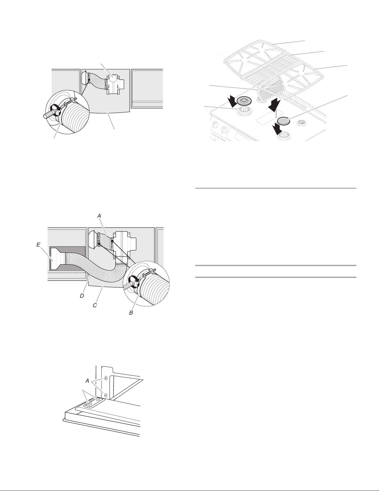
Connect flexible vent duct to range and connect vent system
to blower motor outlet
Top View
A
E
11. Insert downdraft vent filter and place vent grate over opening.
Replace grates and burner caps.
A
B
A
D
C
A. Grate
B. Vent grate
C. Burner caps
D. Filter
12. Reconnect power.
Electronic Ignition System
Initial lighting and gas flame adjustments
Cooktop and oven burners use pilotless igniters in place of
standing pilots. When the cooktop control knob is turned to the
“LITE” position, the system creates a spark to light the burner.
This sparking continues, as long as the control knob is turned to
“LITE.”
When the oven control is turned to the desired setting, a glow bar
igniter heats and ignites the gas.
BLOWER
D
C
B
A. Flexible vent duct to range
B. Vent clamp
C. Range
D. Vent system
E. Side venting outlet
10. Replace access panel by aligning catches with the studs on
the range. Press the access panel forward onto the studs and
drop downward to engage.
A
B
A. Studs
B. Catches
Check Operation of Cooktop Burners
Standard Surface Burners
Push in and turn each control knob to the “LITE” position.
The flame should light within 4 seconds. The first time a burner is
lit it may take longer than 4 seconds to light because of air in the
gas line.
If burners do not light properly:
■ Turn cooktop control knob to the “OFF” position.
■ Check that the range is plugged in and the circuit breaker has
not tripped or the household fuse has not blown.
■ Check that the gas shutoff valves are set to the “open”
position.
■ Check that burner caps are properly positioned on burner
bases.
Repeat start-up. If a burner does not light at this point, turn the
control knobs to “Off” and contact your dealer or authorized
service company for assistance.
19
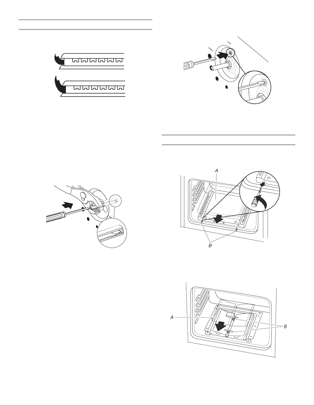
Adjust Flame Height
B
Adjust the height of top burner flames. The cooktop “low” burner
flame should be a steady blue flame approximately ¼" (0.64 cm)
high.
A
B
A. Low flame
B. High flame
To adjust standard burners:
The flame can be adjusted using the adjustment screw in the
center of the valve stem. The valve stem is located directly
underneath the control knob.
If the “low” flame needs to be adjusted:
1. Light 1 burner and turn to lowest setting.
2. Remove the control knob.
Hold the knob stem in the low position using a pair of pliers. Use
an ¹⁄₈" (3.0 mm) flat-blade screwdriver to turn the screw located in
the center of the control knob stem until the flame is the proper
size.
Insert an ¹⁄₈" (3.0 mm) flat-blade screwdriver into adjustment
locations shown in the following illustration and engage the
slotted screw. Turn the screw until the flame is the proper size.
OFF
HIGH
3. Replace the control knob.
4. Test the flame by turning the control from “LO” to “HI,”
checking the flame at each setting.
Check Operation of Oven Bake Burner
1. Remove the oven rack.
2. Using a Phillips screwdriver, remove and set aside the 2 oven
bake burner cover screws located at the front of the oven.
A
3. Replace the control knob.
4. Test the flame by turning the control from “LO” to “HI,”
checking the flame at each setting.
5. Repeat above steps for each burner.
To adjust double burner:
1. Light burner and turn to lowest setting where both inner and
outer burners are lit.
2. Remove the control knob.
B
A. Bake burner cover
B. Bake burner cover screws
3. Lift up and remove oven bake burner cover.
4. Unscrew 2 wing nuts and remove oven baffle.
A
A. Oven baffle
B. Wing nuts
20
 Loading...