


INSTALLATION INSTRUCTIONS
SLIDE-IN DOWNDRAFT RANGES
INSTRUCTIONS D’INSTALLATION
DES CUISINIÈRES À ÉVACUATION PAR LE BAS
ENCASTRABLES
Table of Contents/Table des matières
RANGE SAFETY........................................................................ |
2 |
INSTALLATION REQUIREMENTS .......................................... |
4 |
Tools and Parts .................................................................... |
4 |
Location Requirements ........................................................ |
5 |
Venting Requirements .......................................................... |
7 |
Electrical Requirements – U.S.A. Only ................................. |
9 |
Electrical Requirements – Canada Only ............................. |
10 |
Gas Supply Requirements ................................................. |
10 |
INSTALLATION INSTRUCTIONS ......................................... |
12 |
Unpack Range ................................................................... |
12 |
Install Anti-Tip Bracket........................................................ |
12 |
Position the Blower Location Template ............................. |
13 |
Install the Downdraft System ............................................. |
14 |
Make Gas Connection ........................................................ |
16 |
Level Range ........................................................................ |
16 |
Install Blower ....................................................................... |
17 |
Adjust Leveling Legs .......................................................... |
19 |
Verify Anti-Tip Bracket Is Installed and Engaged ................ |
19 |
Electronic Ignition System .................................................. |
19 |
Oven Door .......................................................................... |
20 |
Complete Installation.......................................................... |
20 |
GAS CONVERSIONS............................................................. |
22 |
LP Gas Conversion............................................................. |
22 |
Natural Gas Conversion..................................................... |
24 |
Adjust Flame Height........................................................... |
26 |
SÉCURITÉ DE LA CUISINIÈRE ............................................ |
27 |
EXIGENCES D’INSTALLATION ............................................ |
29 |
Outillage et pièces ............................................................. |
29 |
Exigences d’emplacement ................................................. |
30 |
Exigences concernant l’évacuation ................................... |
32 |
Spécifications électriques – Canada seulement................. |
34 |
Spécifications de l’alimentation en gaz .............................. |
34 |
INSTRUCTIONS D’INSTALLATION ...................................... |
36 |
Déballage de la cuisinière................................................... |
36 |
Installation de la bride antibasculement............................. |
36 |
Positionnement du gabarit indiquant l’emplacement |
|
du ventilateur ..................................................................... |
37 |
Installation du circuit d’évacuation par le bas ................... |
38 |
Raccordement au gaz ......................................................... |
40 |
Réglage de l’aplomb de la cuisinière .................................. |
40 |
Installation du ventilateur .................................................... |
41 |
Réglage des pieds de nivellement ..................................... |
43 |
Vérifier que la bride antibasculement est bien installée |
|
et engagée........................................................................... |
43 |
Système d’allumage électronique ....................................... |
43 |
Porte du four........................................................................ |
44 |
Achever l’installation........................................................... |
44 |
CONVERSIONS POUR CHANGEMENT DE GAZ................. |
46 |
Conversion pour l’alimentation au propane........................ |
46 |
Conversion pour l’alimentation au gaz naturel.................... |
48 |
Réglage de la taille des flammes........................................ |
50 |
IMPORTANT:
Save for local electrical inspector’s use.
IMPORTANT :
À conserver pour consultation par l’inspecteur local des installations électriques.
W10787365A

RANGE SAFETY
IMPORTANT: Do not install a ventilation system that blows air downward toward this gas cooking appliance. This type of ventilation system may cause ignition and combustion problems with this gas cooking appliance resulting in personal injury or unintended operation.
2
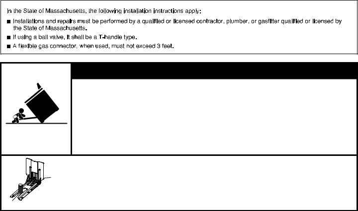
 WARNING
Tip Over Hazard A child or adult can tip the range and be killed.
Install anti-tip bracket to floor or wall per installation instructions.
Slide range back so rear range foot is engaged in the slot of the anti-tip bracket. Re-engage anti-tip bracket if range is moved.
Do not operate range without anti-tip bracket installed and engaged.
Failure to follow these instructions can result in death or serious burns to children and adults.
Anti-Tip
Bracket
Range Foot
To verify the anti-tip bracket is installed and engaged:
•Slide range forward.
•Look for the anti-tip bracket securely attached to floor or wall.
•Slide range back so rear range foot is under anti-tip bracket.
•See installation instructions for details.
3

INSTALLATION REQUIREMENTS
Tools and Parts
Gather the required tools and parts before starting installation. Read and follow the instructions provided with any tools listed here.
Tools Needed
■Tape measure
■Phillips screwdriver
■Flat-blade screwdriver
■¹⁄8" (3 mm) flatblade screwdriver
■Level
■Drill
■Adjustable wrench
■Slip joint pliers
■Pipe wrench
■15⁄16" (2.4 cm) combination wrench
■¹⁄8" (3.2 mm) drill bit (for wood floors)
■Marker or pencil
Parts Supplied
■5¹⁄2" hole saw (round ducting)
■Saw for 3¹⁄4" x 10" rectangle vent
■#2 square bit and driver
■Flashlight
■Masking tape
■Pipe-joint compound resistant to natural and LP gases
■3⁄16" (4.8 mm) carbide-tipped masonry drill bit (for concrete/ ceramic floors)
■Noncorrosive leak-detection solution
■Sheet metal aluminum tape
For LP/Natural Gas Conversions
■½" (13 mm) combination wrench
■¼" (6 mm) nut driver
■9⁄32" (7 mm) nut driver
Check that all parts are included.
■LP/Natural gas conversion kit (dual fuel models only)
■Blower mounting/venting template
■Grease filter (packaged in place)
■Oven racks (3)
■Blower motor kit (under unit)
■Blower cover kit (packed in cavity)
■10-32 hex nuts (attached to terminal block) (3)
■Direct wire lugs (3)
■#12 x 15⁄8" (4.1 cm) screws (for mounting anti-tip bracket) (2)
■Anti-tip bracket (inside oven cavity)
Anti-tip bracket must be securely mounted to the back wall or floor. Thickness of flooring may require longer screws
to anchor bracket to subfloor. Longer screws are available from your local hardware store.
Parts Needed
■Use an approved vent cap for proper performance. If an alternate wall or roof cap is used, be certain the cap size is not reduced and that it has a backdraft damper.
■After determining your vent installation, one of the following is needed:
5" (12.7 cm) Round surface wall cap damper – Order Part Number A405.
6" (15.2 cm) Round surface wall cap damper – Order Part Number A406.
NOTE: If using 6" (15.2 cm) round venting, you will need a 5" (12.7 cm) to 6" (15.2 cm) round vent transition.
3¼" x 10" (8.3 x 25.4 cm) Surface wall cap damper – Order Part Number A403.
To order, see the “Assistance or Service” section of the Use and Care Guide:
–Metal ducting
–Vent clamp
–Aluminum foil tape
Check local codes and consult gas supplier. Check existing gas supply and electrical supply. See the appropriate “Electrical Requirements” and “Gas Supply Requirements” sections.
It is recommended that all electrical connections be made by a licensed, qualified electrical installer.
Optional Parts
To purchase these or any other accessories, please reference the “Accessories” section of the Use and Care Guide for contact information.
■Side Trim Kits:
5⁄8" (1.7 cm) Black – Order Part Number W10675026 5⁄8" (1.7 cm) Stainless Steel – Order Part Number
W10675028
1¹⁄8" (2.9 cm) Black – Order Part Number W10731886
1¹⁄8" (2.9 cm) Stainless Steel – Order Part Number W10731887
■Backsplash Kits:
High 6" (15.2 cm) Black – Order Part Number W10655449
High 6" (15.2 cm) Stainless Steel – Order Part Number W10655450
4
Location Requirements
IMPORTANT: Observe all governing codes and ordinances. Do not obstruct flow of combustion and ventilation air.
■It is the installer’s responsibility to comply with installation clearances specified on the model/serial/rating plate. The model/serial/rating plate is located behind the oven door on the top right-hand side of the oven frame.
■The range should be located for convenient use in the kitchen.
■Recessed installations must provide complete enclosure of the sides and rear of the range.
■To eliminate the risk of burns or fire by reaching over the heated surface units, cabinet storage space located above the surface units should be avoided. If cabinet storage
is to be provided, the risk can be reduced by installing a range hood or microwave hood combination that projects horizontally a minimum of 5" (12.7 cm) beyond the bottom of the cabinets.
■All openings in the wall or floor where range is to be installed must be sealed.
■Cabinet opening dimensions that are shown must be used. Given dimensions are minimum clearances.
■The anti-tip bracket must be installed. To install the anti-tip bracket shipped with the range, see “Install Anti-Tip Bracket” section.
■Grounded electrical supply is required. See the appropriate “Electrical Requirements” section.
■Proper gas supply connection must be available. See “Gas Supply Requirements” section.
■Contact a qualified floor covering installer to check that the floor covering can withstand at least 200°F (93°C).
■Use an insulated pad or ¼" (0.64 cm) plywood under range if installing range over carpeting.
IMPORTANT: To avoid damage to your cabinets, check with your builder or cabinet supplier to make sure that the materials used will not discolor, delaminate, or sustain other
damage. This oven has been designed in accordance with the requirements of UL and CSA International and complies with the maximum allowable wood cabinet temperatures of 194°F (90°C).
Mobile Home – Additional Installation Requirements
The installation of this range must conform to the Manufactured Home Construction and Safety Standard, Title 24 CFR,
Part 3280 (formerly the Federal Standard for Mobile Home Construction and Safety, Title 24, HUD Part 280). When such standard is not applicable, use the Standard for Manufactured Home Installations, ANSI A225.1/NFPA 501A or with local codes.
In Canada, the installation of this range must conform with the current standards CAN/CSA-A240-latest edition or with local codes.
Mobile Home Installations Require:
■When this range is installed in a mobile home, it must be secured to the floor during transit. Any method of securing the range is adequate as long as it conforms to the standards listed above.
■Four-wire power supply cord or cable must be used in a mobile home installation. The appliance wiring will need to be revised. See “Electrical Requirements – U.S.A. Only” section.
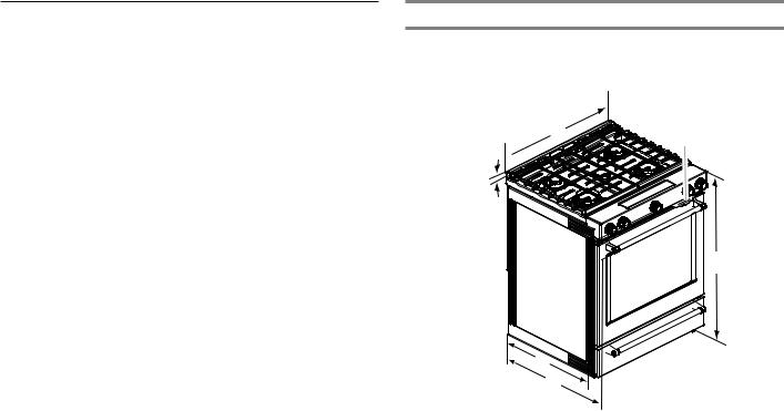
Product Dimensions
This manual covers several models. Your model may appear different from the models depicted. Dimensions given are maximum dimensions across all models.
B  C
C
A 
D
E
F
A.1³⁄16" (3.0 cm) height from cooktop to top of vent
B.297⁄8" (75.9 cm)
C.Model/serial/rating plate (located behind the oven door on the top right-hand side of the oven frame)
D.36" (91.4 cm) height to top of cooktop edge with leveling legs screwed in all the way*
E.285⁄16" (71.9 cm) max. depth from front of console to back of range
F.287⁄8" (73.3 cm) max. depth from handle to back of range
IMPORTANT: Range must be level after installation. Follow
the instructions in the “Level Range” section. Using the cooktop as a reference for leveling the range is not recommended.
*Range can be raised approximately 1" (2.5 cm) by adjusting the leveling legs.
5
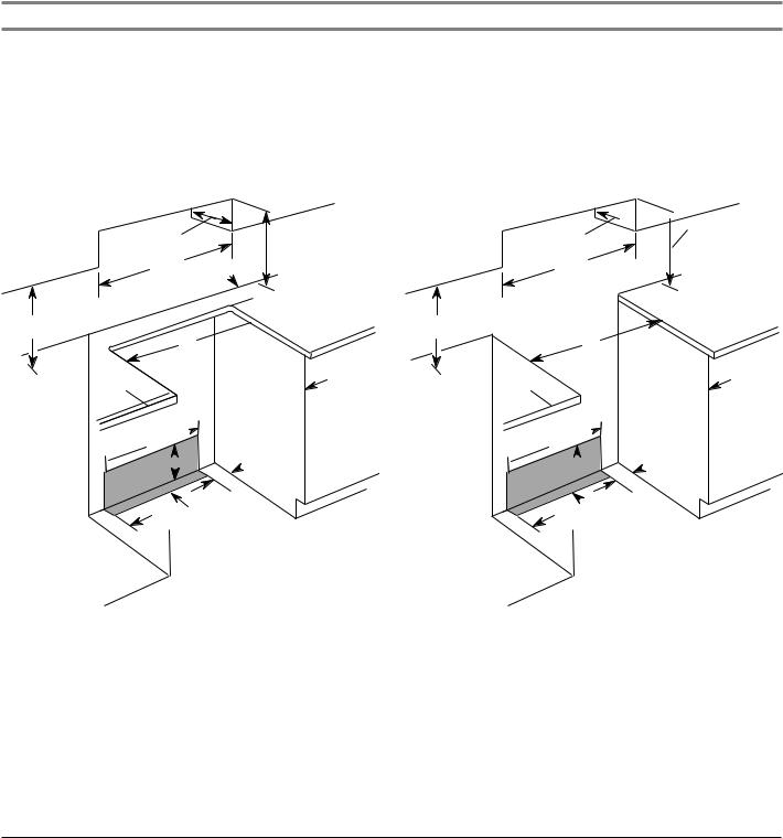
Cabinet Dimensions
Cabinet opening dimensions shown are for 25" (64.0 cm) countertop depth, 24" (61.0 cm) base cabinet depth and 36" (91.4 cm) countertop height.
IMPORTANT: If installing a range hood or microwave hood combination above the range, follow the range hood or microwave hood combination installation instructions for dimensional clearances above the cooktop surface.
Range may be installed next to combustible walls with zero clearance.
NOTE: When installed in a slide-in cutout, the front of oven door may protrude beyond the base cabinet.
Slide-in Cutout Freestanding Cutout
D 
 D
D
B  B
B
C C
 M
M
A  A
A
E E
L L
F  F
F 
H  H
H 

 I
I  J
J 
 I
I  J G
J G 

 G
G 


K  K
K
J  J
J 
A.18" (45.7 cm) upper side cabinet to countertop
B.13" (33 cm) max. upper cabinet depth
C.30" (76.2 cm) min. opening width
D.For minimum clearance to top of cooktop, see NOTE*.
E.30" (76.2 cm) min. opening width
F.3" (7.6 cm) min. clearance from both sides of range to side wall or other combustible material
G.The shaded area is recommended for installation of rigid gas pipe and grounded outlet.
H.203/8" (51.8 cm)
I.7¹¹⁄16" (19.5 cm)
J.4¹³⁄16" (12.2 cm)
K.3¹¹⁄16" (9.4 cm) plus measurement of M
L.Cabinet door or hinges should not extend into the cutout.
M.Remaining counter depth should not exceed 2¼" (5.7 cm).
A.18" (45.7 cm) upper side cabinet to countertop
B.13" (33 cm) max. upper cabinet depth
C.30" (76.2 cm) min. opening width
D.For minimum clearance to top of cooktop, see NOTE*.
E.30" (76.2 cm) min. opening width
F.3" (7.6 cm) min. clearance from both sides of range to side wall or other combustible material
G.The shaded area is recommended for installation of rigid gas pipe and grounded outlet.
H.203/8" (51.8 cm)
I.7¹¹⁄16" (19.5 cm)
J.4¹³⁄16" (12.2 cm)
K.3¹¹⁄16" (9.4 cm)
L.Cabinet door or hinges should not extend into the cutout.
*NOTE: 24" (61.0 cm) minimum when bottom of wood or metal cabinet is shielded by not less than ¹⁄4" (0.64 cm) flame retardant millboard covered with not less than No. 28 MSG sheet steel, 0.015" (0.4 mm) stainless steel, 0.024" (0.6 mm) aluminum or 0.020" (0.5 mm) copper.
30" (76.2 cm) minimum clearance between the top of the cooking platform and the bottom of an uncovered wood or metal cabinet.
6
Venting Requirements
IMPORTANT: This range must be exhausted outdoors unless you are using ductless venting. See the “Venting Methods” section.
■Do not terminate the vent system in an attic or other enclosed area.
■Use an approved vent cap for proper performance. If an alternate wall or roof cap is used, be certain the cap size is not reduced and that it has a backdraft damper.
■Vent system must terminate to the outside unless you are using a ductless vent kit.
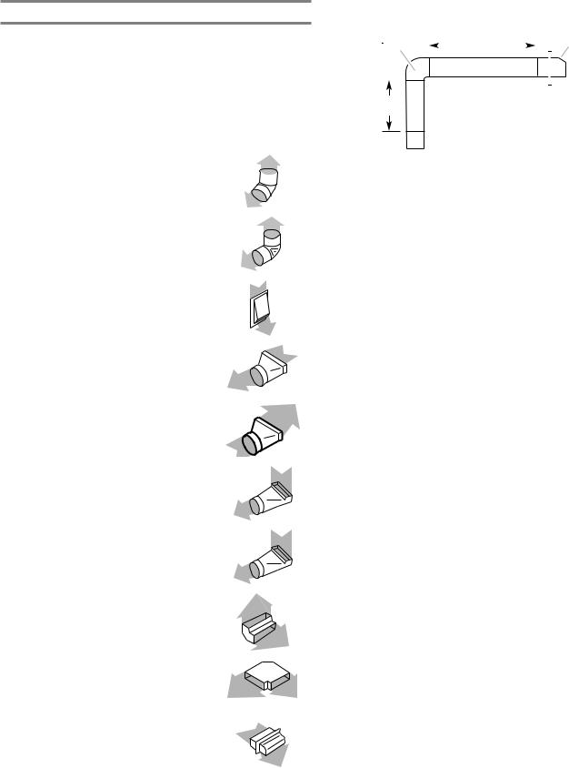
■Use a 5" (12.7 cm) or 6" (15.2 cm) round metal vent or a 3¼" x 10" (8.3 cm x 25.4 cm) rectangular vent.
■Rigid metal vent is recommended. For best performance, do not use plastic or metal foil vent.
■If a joist or stud must be cut, then a supporting frame must be constructed.
■The size of the vent should be uniform.
■The vent system must have a damper.
■Seal all joints in the vent system.
■Use caulking to seal exterior wall or roof opening around the cap.
■Determine which venting method is best for your application.
For Best Performance:
■Use 26-gauge minimum galvanized or 25-gauge minimum aluminum metal vent. Poor quality pipe fittings can reduce airflow. For external venting, flexible metal vent is not recommended.
NOTES:
■For external venting, flexible metal vent is not recommended. Flexible vent creates back pressure and air turbulence that greatly reduce performance.
■Local codes may require a heavier gauge material.
■Metal duct may be reduced to 30-gauge galvanized steel or 26-gauge aluminized steel if allowed by local codes. This reduction is based on information in the International Residential Codes Section M1601.1 (2006 edition).
■Avoid installing 2 elbows together.
■Use no more than three 90° elbows.
■Make sure there is a minimum of 18" (45.7 cm) of straight vent between the elbows if more than one elbow is used. Elbows too close together can cause excess turbulence that reduces airflow.
■Do not use a 5" (12.7 cm) elbow in a 6" (15.2 cm) or 3¼" x 10" (8.3 x 25.4 cm) system.
■Do not reduce to a 5" (12.7 cm) system after using a 6" (15.2 cm) or 3¼" x 10" (8.3 x 25.4 cm) fittings.
■Avoid forming handmade crimps. Handmade crimps may restrict airflow.
The length of vent system and number of elbows should be kept to a minimum to provide efficient performance.
The maximum equivalent length of the vent system is 60 ft (18.3 m). For altitudes above 4,500 ft (1272 m), reduce recommended vent run by 20% for best performance.
Cold Weather Installations
An additional backdraft damper should be installed to minimize backward cold air flow and a thermal break installed to minimize conduction of outside temperatures as part
of the vent system. The damper should be on the cold air side of the thermal break.
Order Part Number 708786A for a 5" (12.7 cm) thermal break. Order Part Number 715557A for a 6" (15.2 cm) thermal break.
To order, see the “Assistance or Service” section of the Use and Care Guide.
Makeup Air
Local building codes may require the use of makeup air systems when using ventilation systems greater than specified CFM of air movement. The specified CFM varies from locale to locale.
Consult your HVAC professional for specific requirements in your area.
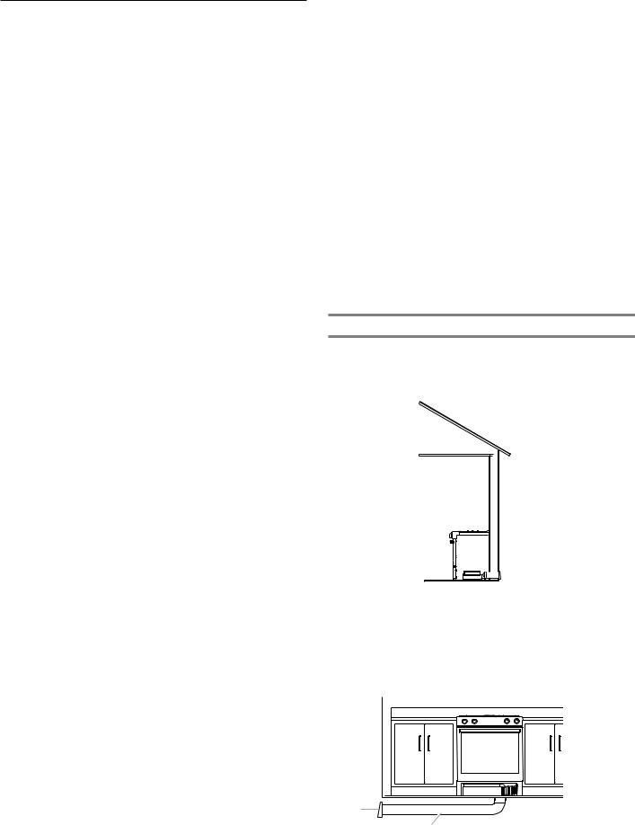
Venting Methods
Common venting methods are shown for a downdraft range. The downdraft range may be vented through the wall or floor.
Wall Venting

 A
A
 B
B
AA. .Walllcap
BB..Venting
Floor Venting
Venting Between Floor Joists
A
B
A.Wall cap
B.Venting
7
Calculating Vent System Length
IMPORTANT: This range is rated at 60 ft (18.3 m) of 6" (15.2 cm) or 30 ft (9.15 m) of 5" (12.7 cm) straight duct. To
calculate the length of the system you need, add the equivalent feet (meters) for each vent piece used in the system.
|
5" (12.7 cm) |
|
or 6" (15.2 cm) |
Vent Piece |
Round |
Straight round |
|
|
|
45° elbow |
2.5 ft |
|
(0.8 m)) |
|
|
90° elbow |
5.0 ft |
|
(1.5 m) |
|
|
6" (15.2 cm) wall cap |
0.0 ft |
|
(0.0 m) |
|
|
3¹⁄4" x 10" (8.3 cm x 25.4 cm) |
4.5 ft |
to 6" (15.2 cm) transition |
(1.4 m) |
|
|
6" (15.2 cm) to 3¹⁄4" x 10" |
1 ft |
(8.3 cm x 25.4 cm) transition |
(0.3 m) |
|
|
3¹⁄4" x 10" (8.3 cm x 25.4 cm) |
5.0 ft |
to 6" (15.2 cm) 90° elbow |
(1.5 m) |
transition |
|
|
|
6" (15.2 cm) to 3¹⁄4" x 10" |
5.0 ft |
(8.3 cm x 25.4 cm) 90° elbow |
(1.5 m) |
transition |
|
|
|
3¹⁄4" x 10" (8.3 cm x 25.4 cm) |
5.0 ft |
90° elbow |
(1.5 m) |
|
|
3¹⁄4" x 10" (8.3 cm x |
12.0 ft |
25.4 cm) flat elbow |
(3.7 m) |
|
|
3¹⁄4" x 10" (8.3 cm x |
0.0 ft |
25.4 cm) wall cap |
(0.0 m) |
|
|
Straight 3¹⁄4" x 10" |
|
(8.3 cm x 25.4 cm) |
|
|
|
5" (12.7 cm) thermal break |
2.0 ft |
Part Number 708786A |
(0.6 m) |
6" (15.2 cm) thermal break |
|
Part Number 715557A |
|
|
|
Example 6" (15.2 cm) vent system
Venting Between Floor Joists
90 elbow |
|
|
|
|
|
|
Wall cap |
||
|
|
6 ft (1.8 m) |
|
|
|||||
|
|
|
|
|
|
||||
|
|
|
|
|
|
|
|
|
|
|
|
|
|
|
|
|
|
|
|
|
|
|
|
|
|
|
|
|
|
2 ft
(0.6 m)
Maximum length |
= 60 ft (18.3 m) |
|
|
1- 90° elbow |
= 5 ft (1.5 m) |
8 ft (2.4 m) straight |
= 8 ft (2.4 m) |
1 - wall cap |
= 0 ft (0 m) |
|
|
System length |
= 13 ft (3.9 m) |
NOTE: For external venting, a flexible vent is not recommended. Flexible vents create back pressure and air turbulence that greatly reduce performance.
8
Electrical Requirements – U.S.A. Only
 WARNING
Electrical Shock Hazard Electrically ground range.
Failure to do so can result in death, fire, or electrical shock.
Be sure that the electrical connection and wire size are adequate and in conformance with the National Electrical Code, ANSI/ NFPA 70-latest edition and all local codes and ordinances.
A copy of the above code standards can be obtained from: National Fire Protection Association
1 Batterymarch Park
Quincy, MA 02169-7471
WARNING: Improper connection of the equipment-grounding conductor can result in a risk of electric shock. Check with a qualified electrician or service technician if you are in doubt as to whether the appliance is properly grounded. Do not modify the power supply cord plug. If it will not fit the outlet, have a proper outlet installed by a qualified electrician.
Electrical Connection
Check local codes and consult gas supplier. Check existing electrical supply and gas supply. See “Gas Supply Requirements” section.
It is recommended that all electrical connections be made by a licensed, qualified electrical installer.
■Range must be connected to the proper electrical voltage and frequency as specified on the model/serial/rating plate. The model/serial/rating plate is located on the right vertical surface of the oven door frame. Refer to the illustrations
in the “Product Dimensions” section of the “Location Requirements” section.
■This range is manufactured with a 4-wire power supply cord rated at 240 volts, 40 amps, rated at 194°F (90°C) and investigated for use with this range.
|
|
Specified Rating of |
|
|
|
Power Supply Cord Kit |
|
Range Rating* |
|
and Circuit Protection |
|
120/240 Volts |
120/208 Volts |
Amps |
Temp Rating |
|
|
|
|
8.8–16.5 kW |
7.8–12.5 kW |
40 or 50 |
194°F (90°C) |
16.6–22.5 kW |
12.6–18.5 kW |
50 |
194°F (90°C) |
|
|
|
|
*The NEC calculated load is less than the total connected load listed on the model/serial/rating plate.
■When a 4-wire, single phase 240 volt, 60 Hz., AC only electrical supply is available, a 40-amp minimum circuit protection is required on 30" (76.2 cm) ranges, fused on both sides of the line.
■A time-delay fuse or circuit breaker is recommended.
■This range is equipped with a UL or CSA International Certified Power Cord intended to be plugged into
a standard 14-50R wall receptacle. Be sure the wall receptacle is within reach of range’s final location.
■Do not use an extension cord.
■The wiring diagram is located on the back of the range or in a clear plastic bag.
9
Electrical Requirements – Canada Only
 WARNING
Electrical Shock Hazard Electrically ground range.
Failure to do so can result in death, fire, or electrical shock.
Be sure that the electrical connection and wire size are adequate and in conformance with the CSA Standard C22.1, Canadian Electrical Code, Part 1 – latest edition, and all local codes and ordinances.
A copy of the above code standards can be obtained from: Canadian Standards Association
178 Rexdale Blvd.
Toronto, ON M9W 1R3 CANADA
■Check with a qualified electrical installer if you are not sure the range is properly grounded.
|
|
Specified Rating of |
|
|
|
Power Supply Cord Kit |
|
Range Rating* |
|
and Circuit Protection |
|
120/240 Volts |
120/208 Volts |
Amps |
Temp Rating |
|
|
|
|
8.8–16.5 kW |
7.8–12.5 kW |
40 or 50 |
194°F (90°C) |
16.6–22.5 kW |
12.6–18.5 kW |
50 |
194°F (90°C) |
|
|
|
|
*The NEC calculated load is less than the total connected load listed on the model/serial/rating plate.
■When a 4-wire, single phase 240 volt, 60 Hz., AC only electrical supply is available, a 40-amp minimum circuit protection is required on 30" (76.2 cm) ranges, fused on both sides of the line.
■A time-delay fuse or circuit breaker is recommended.
■This range is equipped with a UL or CSA International Certified Power Cord intended to be plugged into a standard 14-50R wall receptacle. Be sure the wall receptacle is within reach of range’s final location.
■Do not use an extension cord.
■The wiring diagram is located on the back of the range or in a clear plastic bag.
Gas Supply Requirements
 WARNING
Explosion Hazard
Use a new CSA International approved gas supply line. Install a shut-off valve.
Securely tighten all gas connections.
If connected to LP, have a qualified person make sure gas pressure does not exceed 14" (36 cm) water column.
Examples of a qualified person include:
licensed heating personnel,
authorized gas company personnel, and authorized service personnel.
Failure to do so can result in death, explosion, or fire.
Observe all governing codes and ordinances.
IMPORTANT: This installation must conform with all local codes and ordinances. In the absence of local codes, installation must conform with American National Standard, National Fuel Gas Code ANSI Z223.1 – latest edition or CAN/ CGA B149 – latest edition.
IMPORTANT: Leak testing of the range must be conducted according to the manufacturer’s instructions.
Type of Gas
Natural Gas:
■This range is factory-set for use with Natural gas. See “Gas Conversions” section. The model/serial/rating plate located on the oven frame behind the top right-hand side of the oven door has information on the types of gas that can be used. If the types of gas listed do not include the type of gas available, check with the local gas supplier.
LP Gas Conversion:
Conversion must be done by a qualified service technician.
No attempt shall be made to convert the appliance from the gas specified on the model/serial/rating plate for use with a different gas without consulting the serving gas supplier. See “Gas Conversions” section.
Gas Supply Line
■Provide a gas supply line of ¾" (1.9 cm) rigid pipe to the range location. A smaller size pipe on longer runs may result in insufficient gas supply. With LP gas, piping or tubing size can be ½" (1.3 cm) minimum. Usually, LP gas suppliers determine the size and materials used in the system.
NOTE: Pipe-joint compounds that resist the action of LP gas must be used. Do not use TEFLON®† tape.
†®TEFLON is a registered trademark of E.I. Du Pont De Nemours and Company.
10
Flexible Metal Appliance Connector:
■If local codes permit, a new CSA design-certified, 4 to 5 ft (122 to 152.4 cm) long, ½" or ¾" (1.3 or 1.9 cm) I.D.
(inside diameter), flexible metal appliance connector may be used for connecting range to the gas supply line.
■A ½" (1.3 cm) male pipe thread is needed for connection to the female pipe threads of the inlet to the appliance pressure regulator.
■Do not kink or damage the flexible metal tubing when moving the range.
■Must include a shut-off valve:
The supply line must be equipped with a manual shut-off valve. This valve should be located in the same room but external to the range opening, such as an adjacent cabinet. It should be in a location that allows ease of opening and closing. Do not block access to shut-off valve. The valve
is for turning on or shutting off gas to the range.
B
A
C
A.Gas supply line
B.Shut-off valve “open” position
C.To range
Gas Pressure Regulator
The gas pressure regulator supplied with this range must be used. The inlet pressure to the regulator should be as follows for proper operation:
Natural Gas:
Minimum pressure: 5" WCP Maximum pressure: 14" WCP
LP Gas:
Minimum pressure: 11" WCP Maximum pressure: 14" WCP
Contact local gas supplier if you are not sure about the inlet pressure.
Burner Input Requirements
Input ratings shown on the model/serial/rating plate are for elevations up to 2,000 ft (609.6 m).
For elevations above 2,000 ft (609.6 m), ratings are reduced at a rate of 4% for each 1,000 ft (304.8 m) above sea level (not applicable for Canada).
Gas Supply Pressure Testing
Gas supply pressure for testing regulator must be at least 1" (2.5 cm) water column pressure above the manifold pressure shown on the model/serial/rating plate.
Line Pressure Testing Above ½ psi Gauge (14" WCP)
The range and its individual shut-off valve must be disconnected from the gas supply piping system during any pressure testing of that system at test pressures in excess of ½ psi (3.5 kPa).
Line Pressure Testing at ½ psi Gauge (14" WCP) or Lower
The range must be isolated from the gas supply piping system by closing its individual manual shut-off valve during any pressure testing of the gas supply piping system at test pressures equal to or less than ½ psi (3.5 kPa).
11
INSTALLATION INSTRUCTIONS
Unpack Range
 WARNING
Excessive Weight Hazard
Use two or more people to move and install range. Failure to do so can result in back or other injury.
1.Remove shipping materials, tape and film from the range. Keep cardboard bottom under range. Do not dispose of anything until the installation is complete.
2.Remove oven racks and parts package from oven and shipping materials.
3.To remove cardboard bottom, first take 4 cardboard corners from the carton. Stack one cardboard corner on top of another. Repeat with the other 2 corners. Place them lengthwise on the floor behind the range to support
the range when it is laid on its back.
4.Using 2 or more people, firmly grasp the range and gently lay it on its back on the cardboard corners.
5.Remove cardboard bottom.
The leveling legs can be adjusted while the range is on its back. See the “Adjust Leveling Legs” section.
NOTE: To place range back up into a standing position, put
a sheet of cardboard or hardboard on the floor in front of range to protect the flooring. Using 2 or more people, stand range back up onto the cardboard or hardboard.
Install Anti-Tip Bracket
 WARNING
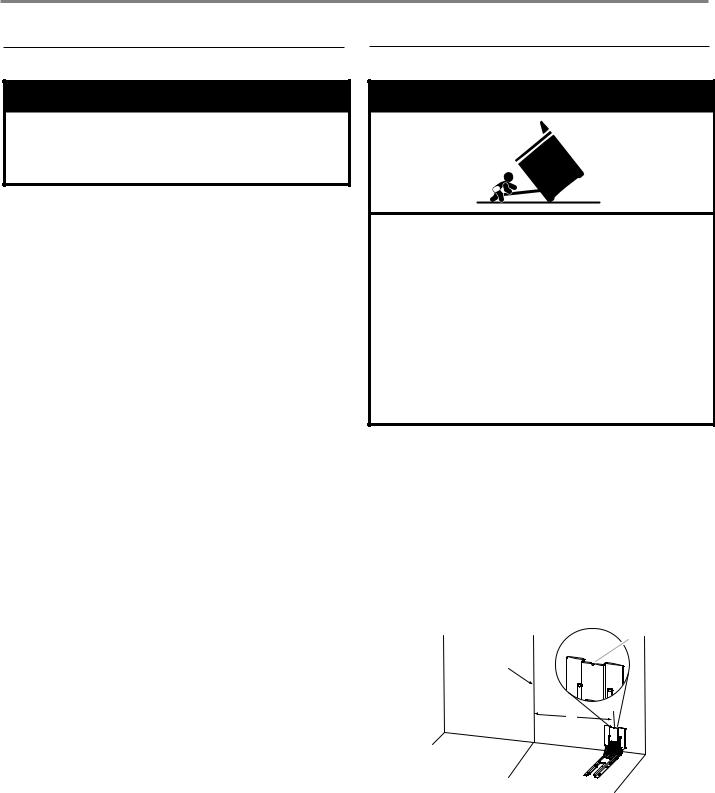
Tip Over Hazard
A child or adult can tip the range and be killed.
Install anti-tip bracket to floor or wall per installation instructions.
Slide range back so rear range foot is engaged in the slot of the anti-tip bracket.
Re-engage anti-tip bracket if range is moved.
Do not operate range without anti-tip bracket installed and engaged.
Failure to follow these instructions can result in death or serious burns to children and adults.
1.Remove the anti-tip bracket from the inside of the oven.
2.Determine which mounting method to use: floor or wall.
If you have a stone or masonry floor, you can use the wall mounting method. If you are installing the range in a mobile home, you must secure the range to the floor.
This anti-tip bracket and screws can be used with wood or metal studs.
3.Determine and mark centerline of the cutout space. The mounting bracket can be installed on either the left-hand or right-hand side of the cutout. Position mounting bracket against the wall in the cutout so that the V-notch of the bracket is 12½" (31.8 cm) from centerline as shown.
B
Centerline
A
A.12½" (31.8 cm)
B.Bracket V-notch
12
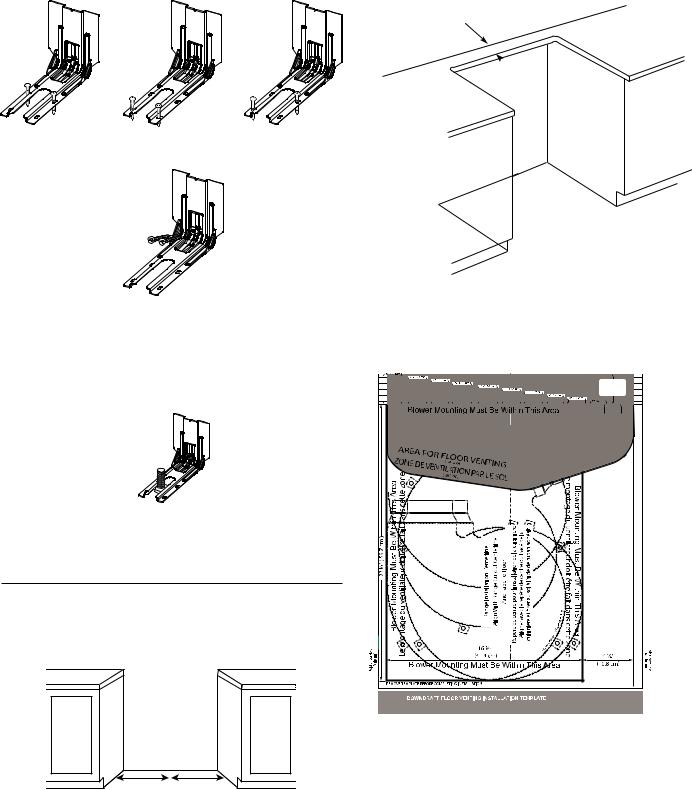
4.Drill two ¹⁄8" (3 mm) holes that correspond to the bracket holes of the determined mounting method. See the following illustrations.
Floor Mounting
Rear position |
Front position |
Diagonal (2 options) |
Wall Mounting |
|
|
5.Using the two #10 x 15⁄8" (4.1 cm) Phillips-head screws provided, mount anti-tip bracket to the wall or floor.
6.Move range close enough to opening to allow for final electrical connections. Remove shipping base, cardboard or hardboard from under range.
7.Move range into its final location, making sure rear leveling leg slides into anti-tip bracket.
8.Move range forward onto shipping base, cardboard or hardboard to continue installing the range, using the following installation instructions.
Position the Blower Location Template
1.Determine and mark the centerline on the floor of the cabinet opening.
 A
A
A. Centerline
2.Locate the blower location template in the Installation Parts Kit.
3.If the countertop extends behind the opening, measure the distance from the back edge of the cabinet cutout to the wall.
 A
A
A.Countertop Filler Depth
4.Fold the top of the blower mounting/venting template on the line that corresponds to the countertop depth measured in Step 3.
|
|
|
|
|
|
|
|
|
|
|
|
|
|
|
|
|
|
Replier sur |
la ligne en |
|
|
|
Fold Here |
|
|
|
|
|
|
|
|
|
|
|
|
|
|
|
|
|
|
|
|
|
|||||
|
|
|
|
|
|
|
|
|
|
|
|
|
|
|
|
|
|
Fold On Line |
Based On |
|
|
|
|
|
|
|
|
|
|
|
|
|
|
|
|
|
|
|
|
|
|
|
Countertop |
Filler Depth |
|
|
|
|
|
|
|
|
|
|
|
|
|
|
|
|
|
|
|
|
|
|
|
|
Measurement |
|
|
|
|
|
|
|
|
|
|
|
|
|
|
|
|
|
|
|
|
|
|
|
fonction de la mesure de |
|
|
|
|
||
|
|
|
|
|
|
|
|
|
|
|
|
|
|
|
|
|
|
profondeur du bouche-fente |
|
|
|
|
||
|
|
|
|
|
|
|
|
|
|
|
|
|
|
|
|
|
|
pour comptoir |
|
|
|
|
||
|
|
|
|
|
|
|
|
|
|
|
|
|
|
|
|
|
|
|
|
|
|
|
|
|
|
No Rear |
|
Countertop |
|
Filler Fold Here |
Le montage du ventilateur doit être fait dans cette zone |
Pas de |
replier ici |
|
|
bouche-fente pour |
|
comptoir arrière pour |
Le montage du ventilateur doit être fait dans cette zone |
|
RETIRER LE GABARIT AVANT DE FINALISER L'INSTALLATION |
|
|
Part Number W10765779B |
GABARIT D'INSTALLATION D'UN SYSTÈME DEVENTILATION À ASPIRATION DESCENDANTE |
© 2015. All rights reserved. |
Numéro de la pièce W10765779B |
|
|
© 2015. Tous droits réservés. |
NOTE: The template has lines every 1/4" (6.4 mm) from the back edge. If the distance measured in the previous step is 11/4"
(32 mm), fold the template on the line labeled 11/4" (32 mm). If there is no countertop filler depth, fold the template at zero depth.
13
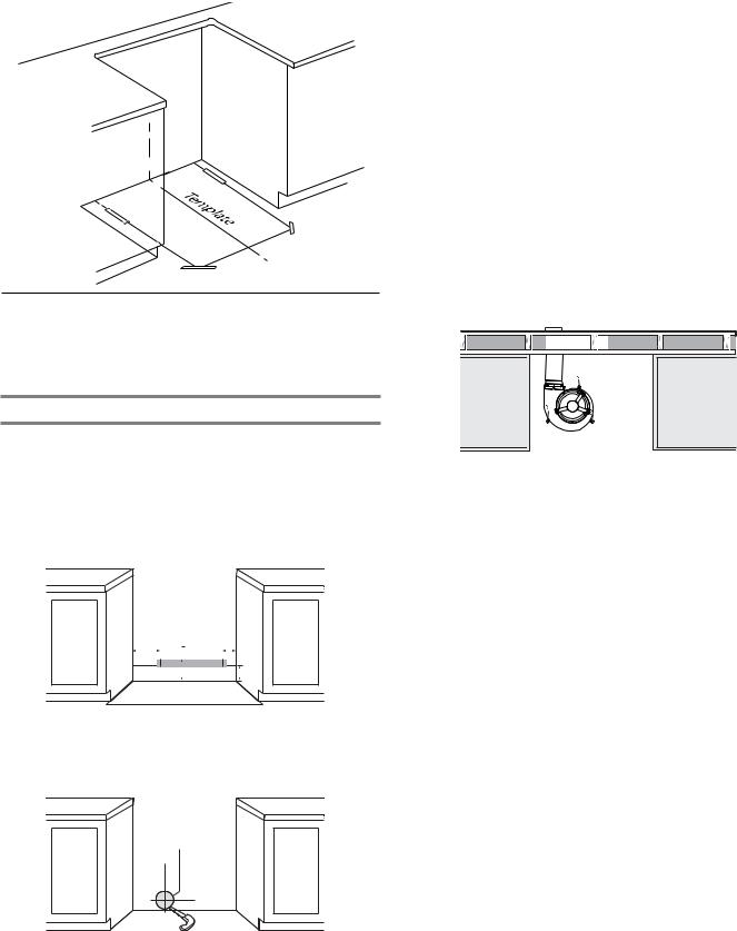
5.Align the template centerline with the centerline marked on the floor. Align the folded edge of the template against the rear wall.
NOTE: Secure the template to the floor with tape.
Install the Downdraft System
Determine which venting method to use: floor or rear wall venting. Go to the section for your type of venting. Consider the location of all utilities and ducts prior to determining final position to ensure proper fit and location.
Rear Wall Venting
1.Determine where within area illustrated below the vent will exit. Mark the vent hole for the type of venting you are using.
IMPORTANT:
■Check for obstructions (plumbing, electrical, wall studs, etc.) before marking the vent hole location.
■The home venting system should terminate within the defined area using 5" (12.7 cm) round venting.
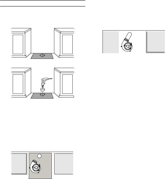
3.Locate the blower.
4.Locate the blower outlet adapter in the installation parts kit.
5.Install the blower outlet adapter to the blower vent using three 8-18 x ³⁄8" screws. Seal the connection with aluminum foil tape.
6.Remove three felt pads from the gasket strip.
7.Remove the paper backing from the felt pads and apply to the bottom of blower motor tabs.
NOTE: Felt pads reduce motor noise and aid in mounting to uneven floors.
8.Position the blower on the template so that the blower outlet adapter aligns with the home venting.
IMPORTANT: Make sure the blower motor is positioned within the area as shown on the template.
9.Connect the home vent system to the blower outlet adapter using sheet metal screws. Seal the connection with aluminum foil tape.
10.Drill three ¹⁄8" (3 mm) pilot holes using the holes in the blower motor tabs as guides.
11.Remove the template.
12.Mount the blower motor to the floor with three #10 x 1" screws provided.
13. Go to the “Make Gas Connection” section.
A |
|
B |
|
C |
|
|
|
|
|
|
|


 D
D
|
|
|
|
A. 12" (30.5 cm) |
C. 8" (20.3 cm) |
||
B. 7½" (19 cm) |
D. 5½" (14 cm) |
||
2. Draw an outline of the vent on the wall and cut the vent hole.
A
A. Vent hole
14
Floor Venting
1.Determine where within the template area that the vent will exit. Mark the vent hole for the type of venting you are using.
IMPORTANT: Check for obstructions (plumbing, electrical, etc.) before marking the vent hole location.
2. Draw and cut the vent hole in the floor.
3.Install the blower outlet adapter to the blower vent using three 8-18 x 3/8" screws. Seal the connection with aluminum foil tape.
4.Remove three felt pads from the gasket strip.
5.Remove the paper backing from the felt pads and apply the bottom of a blower motor tabs.
NOTE: Felt pads reduce motor noise and aid in mounting to uneven floors.
6.Position the blower motor in the cabinet opening so that the blower exhaust venting aligns with the vent hole cut in Step 2.
IMPORTANT: Make sure the blower motor is positioned within the area as shown on the template.
7.Connect the house vent system to the blower outlet adapter using a vent clamp; then wrap connection with aluminum tape.
8.Drill three 1/8" (3 mm) pilot holes using the blower motor tabs as guides.
9.Remove the template.
10.Mount the blower motor to the floor with three #10 x 1" screws provided.
Top View
11. Go to the “Make Gas Connection” section.
15
Make Gas Connection
 WARNING
Explosion Hazard
Use a new CSA International approved gas supply line. Install a shut-off valve.
Securely tighten all gas connections.
If connected to LP, have a qualified person make sure gas pressure does not exceed 14" (36 cm) water column.
Examples of a qualified person include:
licensed heating personnel,
authorized gas company personnel, and authorized service personnel.
Failure to do so can result in death, explosion, or fire.
This range is factory-set for use with Natural gas. To use this range with LP gas, see the “Gas Conversions” section before connecting this range to the gas supply. Gas conversions from Natural gas to LP gas or from LP gas to Natural gas must be done by a qualified installer.
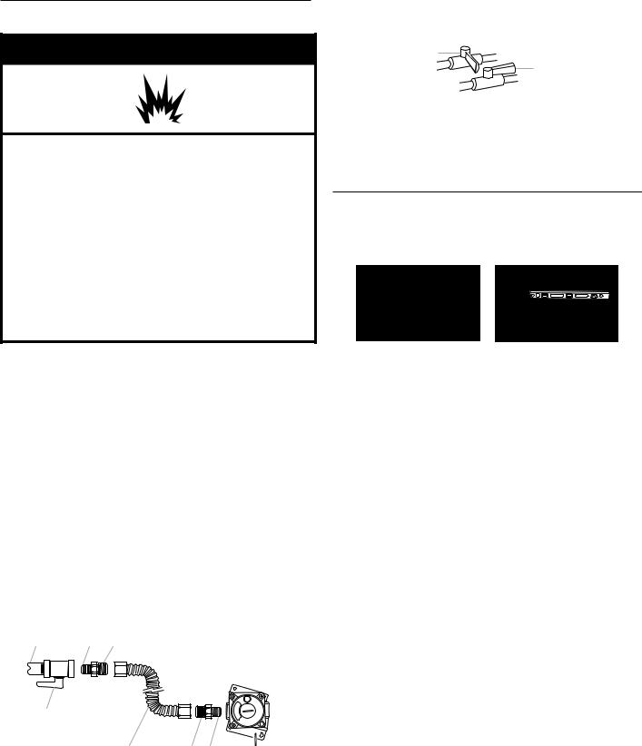
Typical Flexible Connection
1.Apply pipe-joint compound made for use with LP gas to the smaller thread ends of the flexible connector adapters. See B and G in the following illustration.
2.Attach one adapter to the gas pressure regulator and the other adapter to the gas shut-off valve. Tighten both
adapters, being certain not to move or turn the gas pressure regulator.
3.Use a 15⁄16" (2.4 cm) combination wrench and an adjustable wrench to attach the flexible connector to the adapters.
IMPORTANT: All connections must be wrench-tightened. Do not make connections to the gas regulator too tight. Making the connections too tight may crack the regulator and cause a gas leak. Do not allow the regulator to turn when tightening fittings.
A B C
D |
|
|
E |
F G |
H |
A. ½" (1.3 cm) or ¾" (1.9 cm) |
E. Flexible connector |
|
gas pipe |
F. Adapter (must have ½" |
|
B. Use pipe-joint compound. |
[1.3 cm] male pipe thread) |
|
C. Adapter |
G.Use pipe-joint compound. |
|
D. Manual gas shut-off valve |
H. Gas pressure regulator |
|
Complete Connection
1.Open the manual shut-off valve in the gas supply line.
The valve is open when the handle is parallel to the gas pipe.
A
B
A.Closed valve B. Open valve
2.Test all connections by brushing on an approved noncorrosive leak-detection solution. If bubbles appear, a leak is indicated. Correct any leak found.
Level Range
1.Place level on the oven bottom, as indicated in one of the two figures below, depending on the size of the level. Check with the level side to side and front to back.
2.If range is not level, use a wrench or pliers to adjust leveling legs up or down until the range is level.
NOTE: Range must be level for satisfactory baking performance and best cleaning results using AquaLift® Self-Clean Technology.
16
 Loading...