


|
FOR SERVICE TECHNICIAN’S USE ONLY |
|
W11266095A |
NOTE: This sheet contains important Technical Service Data. |
Tech Sheet |
|
Do not remove or destroy |
|
|
|
|
Safety
 DANGER
Electrical Shock Hazard
Only authorized technicians should perform diagnostic voltage measurements.
After performing voltage measurements, disconnect power before servicing.
Failure to follow these instructions can result in death or electrical shock.
 WARNING
Electrical Shock Hazard Disconnect power before servicing.
Replace all parts and panels before operating.
Failure to do so can result in death or electrical shock.
Voltage Measurement Safety Information
When performing live voltage measurements, you must do the following:
 Verify the controls are in the off position so that the appliance does not start when energized.
 Allow enough space to perform the voltage measurements without obstructions.
 Keep other people a safe distance away from the appliance to prevent potential injury.
 Always use the proper testing equipment.
 After voltage measurements, always disconnect power before servicing.
Specifications |
|
ELECTRICAL SUPPLY: |
LOWER SPRAY ARM ROTATION: |
(Under load) 60 Hz, 120 V AC |
25 to 40 rpm |
SUPPLY WATER FLOW RATE: |
UPPER SPRAY ARM ROTATION: |
To fill 2 qt (1.9 L) in 27 seconds, 120 psi maximum, 20 psi minimum |
25 to 35 rpm |
SUPPLY WATER TEMPERATURE: |
REPAIR KITS |
120°F (49°C) (Before starting a cycle, run water from sink faucet until hot.) |
Vinyl Touch-Up Kits: |
WATER CHARGE: |
675576 (Blue), 676453 (White), 676455 (Gray) |
|
|
1.3 gal. (4.8 L) first fill approximate,
1.1 gal. (4.3 L) other fills
|
Control Assembly |
|
|
Control |
|
|
Assembly |
|
|
Push To Release |
|
|
And Rotate |
|
Pin 1 |
Rotate |
|
|
|
Control Panel Snap |
|
Connector |
Locks Into Place |
|
Box |
|
|
Connector Brace |
|
|
(To Remove Pinch Arms |
Buttons On Bottom Of Control |
|
And Rotate) |
|
|
Housing Slides Into Keyhole Slots |
|
|
4 Arms |
On Control Panel To Support |
Rast Connector Pinout |
Pin 1 |
The Control |
|
Meter Check of Loads
Fuse Service and Diagnostic Checks:
■■ For wash/drain motors fuse and triac load fuse.
■■ Verify harness connections to all loads and control are made.
■■ Check stored failure code and/or operation of loads during Service Diagnostics Cycle.
Triac Fuse Diagnostics:
Triac loads; Dispenser, Diverter Motor, Fill Valve, Lower Spray Arm (some models)
■■ If any of the triac loads work, then the triac fuse is OK. Diagnose and repair non-working triac loads.
■■ If all triac loads fail to operate, triac fuse may be open. Check the fuse and replace control if fuse is open. Inspect and check resistances of all loads on fuse. If any loads are open, shorted, or show evidence of overheating or pinched wires, replace loads and/or repair wires.
Wash/Drain Motor Fuse Diagnostics
■■ If both the wash and drain motors fail to operate, motor fuse may be open. Check the fuse and replace control if fuse is open. Inspect and check resistances of both motor loads. If either motor is open, shorted, or shows evidence of overheating or pinched wires, replace loads and/or repair wires.
■■ If only wash or drain motor operates, fuse is OK. Use meter to measure non-operational motor’s three phase resistances. ■■ If a phase is open (> 1,000 W) or unequal to the others, motor is bad. Replace motor.
■■ If all phases are equal and within range (see wash/drain circuit), use meter to verify wiring harness continuity (< 3 W) from control connection to motor phase.
1
FOR SERVICE TECHNICIAN’S USE ONLY
■■ If harness continuity is OK, control is bad. Replace control.
■■ If harness continuity is open or intermittent, harness is bad. Repair/replace harness.
NOTE: If triac or motor fuse is open, inspect and check resistances of all loads on fuse. If any loads are open, shorted, or show evidence of overheating or pinched wires, replace loads and/or repair wires.
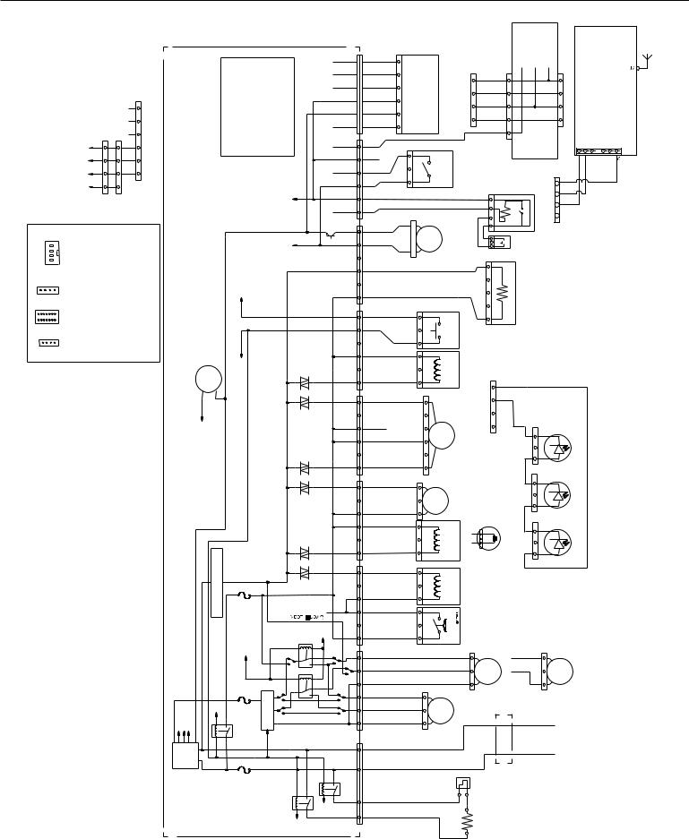
Wiring Diagram
Schematic shown with door switch and all other normally-open contacts open. *Denotes energy-efficient components. Do not substitute.
P13
P1C
P1B
P1A
Terre
GND
DonnéesWide
WideData
5V
V13
Spray Arm Sensor |
4-pin Rast 2.5 |
Capteur bras |
d'aspersion 4 broches RAST 2.5 |
|
Smart UI |
Wide Interface |
4-pin |
Interface utilisateur Wide |
4 broches |
LED |
Displays 14-pin |
|
Afficheurs à DEL 14 broches |
|
Capacitive Touch |
Keyboards 4-pin |
P1-VCC |
P4-Ref Clavier tactile capacitif 4 broches |
P1-VCC P4-Réf |
4 HeaderMinipin-4Miniconnecteur Out)(Wide |
4 |
Connecteurcarte |
|
P1C,P1B,P1A,and P13 InterfaceUserand Spray ConnectorsArm Area connecteursdesZone P1CP1B,P1A,et P13, utilisateurinterface et d'aspersionbras |
diagramdetail(See above) détailléschéma(Voir ci-dessus) |
FoamTurbo DriveDrive |
Lecture moussage |
6543 PCB Edge RAST2.5 (Wide Out) (sortieWide) |
|
Analog/Digital Input Entrée analogique/ numérique |
|||||
|
|
|
|
|
|
|
Lecture turbo |
broches4 |
Wide)(sortie |
Rast2.5 |
|
|
|
OPT Sig |
Sigopt |
|
|
|
|
|
|
NTC Input |
Entrée NTC |
3 |
3 |
2 |
|
|
|
|
Entrée numérique |
2 |
2 |
1 |
|
|
|
Digital Input |
|
|
|
P3 |
|
|
|
|
|
1 |
1 |
|
|
|
|
|
|
P1C |
P13 |
|
|
|
|
3V3 |
Entrée analogique |
P1A, P1B, AND P1C UserInterface Connection Options |
deOptionsconnexion d'interface utilisateur P1A, P1B et P1C |
Controlwill not have all UI and Spray Arm connectors populated. Certainsconnecteurs d'interface utilisateur brasdeet d'aspersion du module de commandene seront pas occupés. |
|
|
|
|
Analog Input |
Alarme sonore |
portede |
|
5V |
|
|||
|
|
|
|
+13V |
|
|
|
|
|
|
Buzzer |
Door Open Detection Détection d'ouverture |
|
|
|
|
|
|
LV Drive Entraînement BT |
|
|
|
|
*Module électronique de commande centralisé (MCC) Carte de circuits imprimés 7¹⁄" x 4¹⁄" (190,2 mm x 107,0 mm) Double face sur substrat FR4 |
TriacLoad Sensing |
|
N - Sensed |
Détection neutre |
|
|
||
|
|
|
|
triac |
|
Dectection) |
|
|
Control*ElectronicCCU 7½"BoardPC x 4¼" xmm(190.2107.0 mm) sided-2FR4 |
|
e |
Fusi |
bl |
(PilotRelay |
|||
|
Detection |
|
||||||
|
|
Fuse |
|
|
||||
|
chargesDétection triac |
|
|
LV Drive |
Entraînement BT |
|||
|
+13V |
|
|
|||||
|
|
|
|
Triac |
d'alimentation) |
|
|
|
|
|
|
|
|
(détection relais |
|
|
|
|
|
|
|
|
débordement/fuite |
|
|
|
|
SupplyLV d'alimentation 13VBT (15 V, 13 V, 3V3)5V, 5 V, 3 V) |
|
|
Détection |
|
|
||
HTCCBus |
LV Drive EntraîneBTment |
Fusi |
Inverter Onduleur |
|
|
|
||
|
Lignes |
|
e |
bl |
|
|
|
|
|
|
|
moteur |
|
|
|
|
|
|
|
|
|
Fuse |
|
|
|
|
|
|
|
Motor |
|
|
|
|
|
HV DC Bus |
Power Lines Supply (15V, |
GND TERRE |
Pilot Relay |
Relais d'alimentation |
HW Enable Signal Signal d'activation matérielle |
|
LV Drive -Entraîne BTment |
|
|
Alimentation électrique |
|
|
|
N-Heater |
Relay élémentRelais (N)chauffant |
|
|
|
|
|
e |
Fusi |
bl |
|
|
|
|
|
|
Fuse |
|
|
|
|
|
|
|
|
|
|
|
LV Drive Entraînement BT |
|
|
Heater-L Relay Relais élément 4 3 chauffant (L) 2 1 1 2 3 4 5 6 1 2 3 4 5 6 1 2 3 4 5 6 1 2 3 4 5 6 1 2 3 4 5 6 1 2 3 4 5 6 1 2 3 4 5 6 1 2 3 4 5 6
P12
R
RD
R
RD
R
RD
P11
Stripe rouge
Red filet
P10 P10
P9
Stripe noir
Black filet
P8 P8
P7
P6
P5
P4
JA
YL
JA
YL
JA
YL
JA
YL
JA
YL
JA
YL
MA BR
MA BR
MA BR
MA BR
VI
V
VI
V
VI
V
VI
V
R
RD
R
RD
R
RD
R
RD
BU
BU
BU
BU
O.W.I. (NTC, Foam, and Turbidity Sensor)
R
RD
R
RD
R
R
R
R
MA |
R |
BR |
|
MA |
R |
BR |
|
MA |
R |
BR |
|
MA |
R |
BR |
|
MA |
R |
BR |
|
MA |
R |
BR |
|
MA |
R |
BR |
|
BUCL |
|
LB |
|
BUCL |
|
LB |
|
BUCL |
|
LB |
|
BL |
|
WH |
|
N |
|
BK |
|
BU/BL |
|
BU/W |
H |
BU/BL |
|
BU/W |
H |
Spray Arm Sensor (on some models)
souilluresdeDétecteur turbidité)mousse,(NTC, |
P13ConnectorTo P13connecteurVers |
4321 |
GRIS |
1234 |
|
|
|
GY |
|
|
|
|
GRIS |
|
|
|
|
GY |
|
|
|
|
GRIS |
|
|
|
|
GY |
|
|
|
|
GRIS |
|
|
|
|
GY |
|
|
|
|
|
5 |
Diverter Position Switch Contact |
Contact de position du clapet de diversion |
M |
Fan Motor 5V, 1W some models) |
|
(on |
|
Door Switch |
Contacteur de la porte |
||
|
Dispenser |
|
Distributeur |
|
M |
|
|
Arm Motor |
|
|
|
|
|
Spray |
M |
|
Diverter Motor |
||
RegenValve |
(on |
ÉlectrovanneRégénération Adoucisseurd’eau (selonmodèle) |
||
|
models) |
|
|
|
|
Softener |
|
|
|
|
some |
|
|
|
|
Water |
|
|
|
|
Fill Valve |
|
Électrovanne |
de remplissage |
|
Contacteur |
de fuite |
|
|
|
Leakage |
(Float) |
Switch |
|
|
|
Softener |
(closed |
(Wide In) |
(Entrée Wide) |
|
|
|
|
||
|
|
AllNotModels Capteur concentration desel adoucisseurpour lorsque(fermé vide) surPastous modèlesles |
|||||||||
|
|
|
when |
|
|
|
|
|
|
|
|
|
|
|
SensorSalt |
empty) |
|
|
|
|
|
|
|
|
4 |
|
|
|
|
|
|
|
|
|
|
Moteurventilateur V,51 W (selonmodèle) |
3 |
|
|
|
|
|
|
33K |
Optional ModelsManyNot Facultatif modèlesdePeu |
||
1 3 1 2 |
|
|
|
Meter |
|
mètre- |
|||||
|
|
|
|
|
Flow |
|
Débit |
|
|
|
|
|
|
|
|
|
|
some models) |
(selon modèle) |
|
|
|
|
|
|
|
|
|
|
Vent Wax Motor (on Moteur linéaire évent |
|
|
|
||
|
|
|
|
|
GRI |
S |
Light in the Tub |
(on some models) |
|||
|
|
|
4 |
|
|
|
|||||
|
|
|
|
|
GY |
|
|
|
|||
|
|
|
3 |
|
GRI |
S |
|
|
|||
|
|
|
|
|
GY |
|
|
|
|
||
models) |
|
|
1 2 |
|
models) |
modèles)certains |
|
132 3 2 1 |
|
||
clapetMoteur diversionde Moteurrampe d'aspersion (selonmodèle) |
ConnectorTo P13 |
|
|
|
|||||||
some(on |
|
|
|
P13connecteur |
|
|
|
|
|
|
|
|
|
|
|
Vers |
|
|
|
|
|
|
|
1 |
|
|
|
Motor |
|
|
(sur |
|
1 |
|
|
or 3 |
|
|
|
|
some(on |
ventilateur |
|
3 2 |
|
||
|
|
|
|
Fan |
|
|
|
|
|
|
|
VSM Drain Pump Motor |
|
|
|
|
|
|
|
Moteur du |
|
|
|
Moteur pompe de vidange à variateur de vitesse |
|
|
|
|
|
|
|||||
Capteur rampe d'aspersion (selon modèle) |
|
2 3 4 |
Wi-Fi Module Module Wi-Fi |
|
|
1 |
|
|
(Wide Out) (Sortie Wide) |
J4 |
|
|
|
|
|
|
|
1 |
|
|
|
GRIS |
|
ConnectorTo P13 connecteurVers P13 |
32 4 |
GY |
|
GRIS |
|
||
GY |
|
||
|
|
GRIS |
|
|
|
GY |
|
|
1 |
|
|
Lampe de la cuve (sur certains modèles)
Lampe DEL Lampe DEL Lampe DEL
Light Light Light
Single Speed Drain Pump Motor |
Moteur pompe de vidange sans variateur |
|
M |
|
M |
M |
VSM Spray Pump Motor Moteur pompe d'aspersion à variateur de vitesse |
BL |
N |
|
Ferrite (1 Loop) Ferrite (boucle de courant) |
WH |
|
|
N |
L |
|
|
|
BK |
|
|
Thermostat (Hi-Limit) Thermostat (limite haute) |
|
|
Heater |
Élément chauffant |
|
|
ennetnA annetnA
2

FOR SERVICE TECHNICIAN’S USE ONLY
Control Pinout
Meter Check of Loads and Fuses
Load must be connected for triac to operate correctly. Meter checks are best made at the control. See illustration below and “Dishwasher Strip Circuits.”
BR/TURQ |
BR |
BU RD/BK |
V |
BR/RD |
RD |
YL |
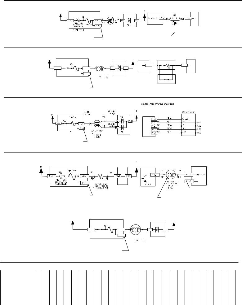
Dishwasher Strip Circuits
The following individual circuits are for use in diagnoses. Do not continue with the diagnosis of the appliance if a fuse has blown, a circuit breaker has tripped, or if there is less than a 120-volt power supply at the wall outlet.
■■ Unplug dishwasher or disconnect power.
■■ Perform resistance checks. To check resistance of a component, disconnect harness leads first.
Door Switch
|
|
|
|
|
(vers moteur lavage, |
|
|
|
|
|
|
|
|
|
|
|
évent et charges triac) |
(vers élément |
(vers variateur de vitesse |
(selon modèle, vers |
|||
|
|
|
|
(vers élément |
|
|
ou moteur de vidange |
|
|||
|
|
|
|
chauffant) |
|
|
chauffant) |
sans variateur) |
|
variateur de vitesse) |
|
|
|
Détection |
|
|
|
|
Relais élément |
|
|
|
|
|
|
contacteur |
Relais élément |
Relais d’alimentation |
|
|
|
|
|||
Résistance |
de porte - |
chauffant K402 (N) |
K400 (L1) |
chauffant K401 (L1) |
|
|
|
||||
entrée |
|
|
|
|
|
|
|||||
contacteur |
|
|
|
|
|
|
|
|
|
|
|
Fermé |
|
|
|
|
|
|
|
|
|
|
|
Ouvert |
VI |
|
|
|
|
|
|
|
|
|
|
VI |
|
|
|
|
|
|
|
|
|
|
|
|
|
|
|
|
|
|
|
|
Microbroche |
Microbroche |
|
Contacteur |
|
Microbroche |
|
Microbroche |
Microbroche |
|
|
|
||||
Module de commande |
porte |
|
|
|
|
|
|
|
|
|
|
|
électronique |
|
|
|
Module de commande électronique |
|
|
|
|
|
|||
|
|
|
|
|
|
|
|
|
||||
Wash/Drain |
|
|
|
Variable Speed |
|
|
|
|
|
Variable Speed |
||
|
|
|
|
|
|
|
|
Wash Motor |
|
|||
|
|
|
Wash Motor |
|
Wash/Drain - On Some Models |
|
|
|||||
|
|
|
|
|
Moteur de la age |
|||||||
Variateur |
|
|
|
Moteur de la age |
|
LAVAGE/VIDANGE - SELON MODÈLE |
||||||
|
|
|
ariateur de itess e |
|
ariateur de itess e |
|||||||
de itess e |
|
|
|
|
|
|
|
|
|
|
|
|
Variable |
P5-1 |
BU |
Pin 3 |
|
|
Variable |
|
P5-1 |
Broche 3Pin 3 |
|
|
|
Speed |
BU |
Pin 2 |
10 - 20 |
|
Speed |
|
|
Broche 2Pin 2 |
|
|
10 - 20 |
|
P5-2 |
|
Controller |
|
P5-2 |
|
|
||||||
Controller |
BU |
Pin 1 |
Pin to Pin |
|
|
Broche 1Pin 1 |
|
|
Pin to Pin |
|||
|
P5-3 |
|
Variateur |
|
P5-3 |
|
|
10 - 20 |
||||
|
|
|
10 - 20 |
|
de itess e |
|
|
|
|
|||
|
|
MAR |
Pin 3 |
|
|
|
|
|
|
|
broche broche |
|
|
P5-4 |
broche broche |
|
|
|
|
|
|
|
|||
|
MAR |
Pin 2 |
L1 |
|
|
|
|
|
|
|
||
|
P5-5 |
|
Motor Fuse |
|
|
|
|
|
N |
|||
|
P5-6 |
MAR |
Pin 1 |
|
|
Fusible oteur |
|
|
|
|
|
|
|
|
Broche 3 |
80 - 100 |
|
N.O. |
N.O. |
|
|
|
|
|
|
|
|
|
|
|
|
|
|
|
||||
Electronic Control |
|
Broche 2 |
Pin to Pin |
|
P4-2 |
K300 |
P5-6 |
|
P5-5 |
P4-1 |
||
|
Broche 1 |
80 - 100 |
|
K400 |
|
|
|
|
|
|||
Module de co ande |
|
Broche 3 |
|
|
|
|
|
|
|
|
||
|
broche broche |
|
|
|
|
Single Speed Drain Motor |
|
|
||||
lectroni u |
e |
|
Broche 2 |
|
Electronic Control |
|
|
|
||||
|
|
|
Variable Speed |
|
|
15 - 60 , 120 V |
Electronic |
|||||
|
|
|
Broche 1 |
|
Module de co ande |
|
||||||
|
|
|
Drain Motor |
|
|
60 Hz, 60 W |
Control |
|
||||
|
|
|
|
|
lectroni u |
e |
|
|
||||
|
|
|
|
Moteur de idange |
|
|
|
|
Moteur de idange |
Module de |
||
|
|
|
|
ariateur de itess e |
|
|
|
|
sans ariateur |
co and |
|
e |
|
|
|
|
|
|
|
|
|
15 - 60 , 120 V |
lectroni u |
e |
|
|
|
|
|
|
|
|
|
|
60 Hz, 60 W |
|
|
|
Water Heating/Heat Dry and Water Sensing with OWI Soil Sensor (Water/Air/Soil/Temperature)
Pump is washing and control monitors temperature during water heating periods. See “Wash/Drain” and “Water Sensing with OWI Sensor (Water/Air/Soil/ Temperature)” circuits.
Fill
|
|
|
électronique |
|
|
N.C. |
|
|
|
|
|
|
|
|
N |
|
|
|
YL |
Pin 1 |
|
Turbidity Drive |
|
L1 |
|
|
|
|
|
|
|
|
|
|
|
|
|
NEU |
Electronic |
P12-6 |
JA |
Broche 1 |
|
Circuit dÊactivation |
O.W.I. Sensor |
||
BK |
|
|
|
|
N.F. |
|
|
|
|
|
|
|
|
|
YL |
Pin 2 |
|
||||||
|
|
|
BU/RD |
|
BU/RD |
|
|
|
|
|
|
WH |
Control |
|
|
|
détecteur turbidité |
Capteur du détecteur |
|||||
|
|
N.O. |
|
|
|
|
|
|
N.O. |
|
|
|
JA |
Broche 2 |
|
||||||||
|
N |
P4-2 |
BU/R |
|
|
BU/R |
|
BU/WH |
P4-4 |
|
P4-1 |
BL |
Module de |
P12-5 |
Foam Drive |
de souillures |
|||||||
|
|
P4-3 |
|
|
|
|
|
|
|
|
K1 |
|
|
YL |
Pin 3 |
Lecture moussage |
Temperature: NTC Thermistor |
||||||
|
|
|
K3 |
|
Hi-Limit |
|
Heater Element |
|
|
|
|
commande |
P12-4 |
JA |
Broche 3 |
OPT Sig |
|||||||
|
|
|
|
|
|
|
|
|
|
|
YL |
Pin 4 |
46K - 52K at 77oF (25oC) |
||||||||||
|
|
|
Heater L1 Relay |
|
Thermostat |
|
8 - 30 |
|
|
|
Heater N Relay |
|
|
électronique |
P12-3 |
JA |
Broche 4 |
|
VCC |
11K - 13K at 140oF (60oC) |
|||
|
|
|
(Also see Door |
|
|
Opens |
|
120V, 60 Hz |
|
|
(Also see Door |
|
|
|
|
YL |
Pin 5 |
|
|
||||
|
|
|
207oF - 217oF |
785W Wet |
|
|
|
Switch Circuit) |
|
|
|
|
|
|
|
Température : |
|||||||
|
|
|
Switch Circuit) |
(97oC - 103oC) |
500W Dry |
|
|
|
|
|
|
|
|
P12-2 |
JA |
Broche 5 |
Ref |
thermistance NTC |
|||||
|
|
Relais élément chauffant - |
Limite haute |
|
Élément chauffant |
|
|
|
|
|
|
|
|
YL |
Pin 6 |
réf |
Thermistance |
46 K à 52 K 77 oF (25 oC) |
|||||
|
|
|
|
Relais élément chauffant - N |
|
|
|
P12-1 |
JA |
Broche 6 |
|
11 K à 13 K 140 oF (60 oC) |
|||||||||||
|
|
L1 (voir également le circuit |
|
|
|
|
|
|
|||||||||||||||
|
|
ouverture du |
|
8 à 30 |
|
(voir également le circuit |
|
|
|
|
|
|
NTC |
|
|||||||||
|
|
|
du contacteur porte) |
|
|
|
|
|
|
|
|
|
|
||||||||||
|
|
|
|
thermostat |
|
120 V, 60 Hz |
|
|
du contacteur porte) |
|
|
|
|
|
|
|
|
Measure NTC resistance at P12-1 and |
|||||
|
|
|
|
207 oF à 217 oF |
785 W (humide) |
|
|
|
|
|
|
|
|
|
|
P12-3 connector disconnected from control. |
|||||||
|
|
|
|
(97 oC à 103 oC) |
500 W (sec) |
|
|
|
|
|
|
|
|
|
|
|
Mesurer la résistance NTC sur les broches P12-1 et P12-3 |
||||||
|
|
|
|
|
|
|
|
|
|
|
|
|
|
|
|
|
|
|
|
|
|
avec le connecteur déconnecté du module de commande |
|
|
|
|
|
|
|
|
|
Float |
|
Float Switch |
|
|
|
|
|
|
|
|
|
|
|
|
|
|
|
|
|
|
|
(In Normal Position) |
|
|
|
|
|
|
|
|
|
|
|
|
|
||||
|
|
|
|
|
|
|
Input |
|
|
|
|
|
|
|
|
|
|
|
|
||||
|
|
|
|
|
|
Holds Switch Closed |
|
|
|
|
|
|
|
|
|
|
|
|
|
||||
|
|
|
|
|
|
|
|
Flotteur |
|
Contacteur |
|
|
|
|
|
|
N |
|
|
|
|
|
|
|
|
|
|
|
|
(à la position normale) |
|
flotteur - |
|
|
|
|
|
|
NEU |
|
|
|
|
|
|||
|
|
|
|
|
|
Il maintient le |
|
entrée |
|
|
|
|
|
|
|
|
|
|
|
|
|||
|
|
|
Triac Fuse |
|
|
contacteur fermé |
|
|
|
|
|
|
|
|
|
|
|
|
|
|
|
||
|
BK |
|
Fusible triac |
|
BR |
|
BR |
|
|
|
|
BR |
BR |
|
|
WH |
|
|
|
|
|
|
|
|
N |
|
N.O. |
|
|
|
|
|
|
|
|
|
BL |
|
|
|
|
|
|
||||
|
P4-2 |
|
P6-1 |
MAR |
|
MAR |
P6-3 |
|
P6-4 |
MAR |
MAR |
P6-6 |
P4-1 |
|
|
|
|
|
|
||||
|
|
K400 |
Pin 3 |
|
Pin 1 |
|
Pin 3 |
Pin 1 |
|
|
|
|
|
|
|
||||||||
|
|
|
|
|
|
|
|
|
|
|
|
|
|
|
|
|
|
|
|||||
|
|
|
Pilot L1 Relay |
|
|
Broche 3 |
|
Broche 1 |
|
|
|
|
Broche 3 |
Broche 1 |
Triac |
|
|
|
|
|
|
|
|
|
|
|
(Also See Door |
|
|
|
|
|
|
|
|
|
Fill Valve |
|
|
|
|
|
|
|
|
|
|
|
|
|
Switch Circuit) |
|
|
|
|
|
|
|
|
|
|
|
|
|
|
|
|
|
|
|
|
|
|
Relais d'alimentation L1 |
|
|
Overfill Switch |
|
|
|
|
|
|
|
|
|
|
|
|
|
|
|
|||
|
|
(voir également le circuit |
|
|
|
|
|
|
|
|
|
|
|
|
|
|
|
|
|
||||
|
|
du contacteur porte) |
|
|
Closed (Normal) < 3 |
|
Electronic Control |
Électrovanne remplissage |
Electronic Control |
|
|
|
|
|
|
|
|||||||
|
|
|
|
|
|
Open (Overfill) > 3 |
|
Module de commande |
|
|
|
|
|
|
|
||||||||
|
|
|
|
|
|
Module de commande |
|
|
|
|
|
|
|
|
|||||||||
|
|
|
Electronic Control |
|
|
Contacteur de |
|
électronique |
|
|
électronique |
|
|
|
|
|
|
|
|||||
|
|
|
Module de commande |
|
|
débordement |
|
|
|
|
No Test Pad On P6-4. |
|
|
|
|
|
|
|
|
|
|||
|
|
|
|
|
Fermé (normal) < 3 |
|
|
|
|
|
|
|
|
|
|
|
|
|
|||||
|
|
|
électronique |
|
|
|
|
|
|
Recommend Using Test Pad On |
|
|
|
|
|
|
|
|
|||||
|
|
|
|
Ouvert (débordement) > 3 |
|
|
|
|
|
|
|
|
|
|
|
|
|||||||
|
|
|
|
|
|
|
|
|
P6-3 For P6-4. |
|
|
|
|
|
|
|
|
|
|||||
Pas de cosse de test sur P6-4 :
Utilisation de la cosse de test sur
P6-3 pour P6-4 recommandée.
Dispenser (Detergent and Rinse Aid) |
|
Dispenser Wax Motor |
|
|
|
120V, 60Hz, 10 Watts |
|
||
|
|
1,400-3,000 |
|
|
|
|
Moteur linéaire-distributeur |
|
|
|
Module de commande électronique |
1400 à 3000 |
|
|
|
120 V, 60 Hz, 10 W |
|
||
|
|
|
||
|
|
Broche 1 |
|
NEU |
|
|
Broche 5 |
WH |
|
|
Fusible - |
|
|
|
|
|
|
|
|
N |
F9 |
VI |
VI |
BL |
|
|
Broche 1 |
Broche 3 |
|
K400
Relais d'alimentation L1 (voir également le circuit du contacteur porte)
La cosse de test sur P9-3 peut encombrer P9-1. Utilisation de la cosse de test sur P10-1 recommandée
Dispenser Solenoid |
|
|
260-300 |
|
|
120V, 60Hz, 17 Watts |
Module de commande électronique |
|
Bobine du distributeur |
||
|
||
260 à 300 |
|
|
120 V, 60 Hz, 17 W |
|
3
FOR SERVICE TECHNICIAN’S USE ONLY
Diverter Valve
Diverter Motor
Moteur clapet de diversion
L1

 usible - N
400 Relais d alimentation L1 voir également le circuit du contacteur porte
odule de commande électroniqu e
Test pad on P7-4 might crowd P7-6
Recommend using test pad on P10-1
roche 3 |
roche 1 |
Diverter valve motor 1,400 to 1,800 120V, 60Hz, 3 Watts
oteur électrovanne distributeur
1,400 to 1,800
120 V, 60 Hz, 3 W
La cosse de test sur P7-4 peut encombrer P7-6. Utilisation de la cosse de test sur P10-1 recommandée
Electronic Control
odule de commande électronique
|
|
|
|
Switch Open >3 W |
|
|
|||
Diverter Sensor |
|
Switch Closed <3 W |
|
|
|||||
Capteur de clapet |
|
Contacteur ouvert : >3 W |
|
|
|||||
de diversion |
|
Contacteur fermé : <3 W |
|
|
|||||
NEU |
|
RD |
|
RD |
|
|
|||
|
|
|
|
||||||
WH |
|
|
|
|
|
|
|||
|
|
|
R |
|
R |
|
|
5V |
|
|
|
|
|
|
|
|
|
|
|
L |
|
|
|
|
|
|
|
|
|
Entrée capteur |
roche 3 |
roche 1 |
|
|
|||||
|
|
|
|
Contacteur de |
Electronic |
||||
|
|
|
|
position du clapet |
|||||
|
|
|
|
|
Control |
||||
|
|
|
|
|
de diversion |
|
|
|
|
|
|
|
|
|
|
|
odule de commande |
||
|
Switch closes momentarily |
|
|
||||||
|
|
|
électronique |
||||||
|
and then reopens as the |
|
|
||||||
|
|
|
|
|
|||||
|
diverter reaches each potential diverter position. |
|
|
||||||
|
Le contacteur se ferme provisoirement avant |
|
|
||||||
|
de se rouvrir lorsque le clapet de diversion atteint |
|
|
||||||
|
chaque position possible. |
|
|
|
|
||||
Water Softener (not all models)
Regeneration Valve |
|
|
|
|
|
|
|
|||
Électrovanne régénération Use top hole of jumper |
|
|
|
|
|
N |
||||
L1 |
|
|
W2 as test point for F9. |
|
|
|
|
|
||
|
|
Utiliser le trou supérieur du conducteur de |
|
|
|
|
NEU |
|||
|
|
|
|
|
|
|
||||
|
|
dérivation W2 comme point de test pour F9 |
|
|
|
|
|
|||
|
BK |
|
N.O. |
Fusible - F9 |
|
VI |
VI |
|
|
WH |
|
N |
P4-2 |
|
P7-3 |
BU |
BU |
P7-1 |
P4-1 |
BL |
|
|
|
|
||||||||
|
|
K400 |
|
Pin 1 |
Pin 3 |
|
||||
|
|
|
|
|
|
|
|
|||
|
|
|
Pilot L1 Rel ay |
Fuse |
|
Broche 1 |
Broche 3 |
Triac |
|
|
|
|
|
(Also see Door |
P10-1 |
|
|
||||
|
|
|
Switch Circuit) |
F9 |
|
Regeneration Valve |
Electronic Control |
|
||
|
|
|
K400 |
Electronic Control |
890 |
1,090 |
|
|||
|
|
Relais d'alimentation L1 |
120V, 60 Hz, 6W |
Module de |
|
|
||||
|
|
(voir également le circuit |
Module de commande |
|
|
commande électronique |
|
|||
|
|
du contacteur porte) |
électronique |
|
Électrovanne régénération |
|
|
|||
|
|
|
890 à 1090 |
|
|
|
||||
|
|
|
|
|
|
|
|
|
||
120V, 60 Hz,6 W
Test pad on P7-3 might crowd P7-6 Recommend using test pad on P10-1
La cosse de test sur P7-3 peut encombrer P7-6 Utilisation de la cosse de test sur P10-1 recommandée
|
|
(Closed when salt low) |
Electronic Control |
||||
|
|
(Fermée lorsque |
|
||||
Salt Level Sensing |
|
Module de |
|||||
Capteur |
concentration |
concentration de sel basse) |
commande |
||||
|
|
|
|
électronique |
|||
de sel |
|
Salt Level Reed Switch |
|
|
|||
|
|
RD |
Contacteur à anche- |
|
RD |
|
|
|
|
R |
Concentration de sel |
|
R P11-1 |
Sensor |
|
5V |
P11-2 |
|
|
|
|||
|
|
Pin 1 |
N.O. |
39 K |
Pin 2 |
Input |
|
|
Broche 1 |
|
Broche 2 |
Capteur - |
|||
|
|
|
|||||
|
Pin 4 |
Broche 4 |
(RD) |
(RD) |
Pin 3 |
Broche 3 |
entrée |
|
Pin1 Broche 1 |
(R) |
(R) |
Pin 3 |
Broche 3 |
|
|
Electronic Control |
|
|
|
|
|
|
|
Module de |
|
|
N.O. |
|
|
|
|
commande |
|
|
|
|
|
|
|
électronique |
|
(Optional Flowmeter) |
|
|
|||
|
|
|
(Débitmétre - option) |
|
|
||
Controlled Lower Spray Arm (not all models)
LOWER SPRAY ARM MOTOR
MOTEUR DE RAMPE D'ASPERSION INFÉRIEURE
Fusible triac
K400 |
K400 |
|
Relais d'alimentation L1 |
||
Pilot L1 Relay |
||
(voir également le circuit |
||
(Also see Door Switch circuit) |
||
du contacteur porte) |
||
Electronic Control |
||
|
||
|
Module de commande électronique |
Test pad on P8-3 might crowd P8-6 and P8-1 Recommend using test pad on P10-1
la prise de test sur P8-3 peut encombrer P8-6 et P8-1 Utilisation de la prise de test sur P10-1 recommandée
(Filet bleu |
|
RD |
(Filet bleu |
|
sur fiche) |
Broche 1 |
sur fiche) |
||
RD |
R |
|
||
R |
|
RD |
|
|
|
|
|
||
Broche 3 |
|
R |
|
|
Broche 5 |
(Filet bleu |
|||
|
||||
sur fiche)


Moteur de la rampe d'aspersion 1890 à 2310 pour chaque bobine 120 V, 60 Hz, 6 W
|
CAPTEUR DE RAMPE D'ASPERSION INFÉRIEURE COMMANDÉE |
|
||
|
NEU |
|
Capteur de la |
|
|
|
|
|
|
WH |
RD R |
Broche 1-5 |
rampe d'aspersion |
|
BL |
|
|
||
GRIS |
Broche 1-4 |
Sortie capteur |
|
|
|
Broche 2-1 |
|||
|
|
|
|
|
|
GRIS |
Broche 1-3 |
|
Broche 2-2 |
|
GRIS |
|
|
|
|
Broche 1-2 |
Données |
Broche 2-3 |
|
|
|
|
|
|
|
GRIS |
Broche 1-1 |
Terre |
Broche 2-4 |
|
|
|
|
|
Electronic Control
Module de commande 


 électronique Module de commande
électronique
Drying
VENT (not all models) |
Electronic Control |
|
|
|
Fan (on some models) |
|
Electronic Control |
|
|
|
|
VENTILATEUR |
(RD stripe |
(RD stripe |
|||
|
|
|
|
|
Module de commande |
|||
ÉVENT (selon modèle) |
Module de commande électronique (RD stripe |
(RD stripe |
|
(selon modèle) |
on plug) |
on plug) |
||
|
électronique |
|||||||
|
|
on plug) |
on plug) |
Electronic Control |
NEU |
(Ligne rouge |
(Ligne rouge |
|
|
|
(Ligne rouge |
|
sur la prise) |
sur la prise) |
|
||
|
|
(Ligne rouge |
|
|
|
|
||
BK |
|
sur la prise) |
sur la prise) |
|
|
|
|
|
|
|
|
|
WH |
MAR |
MAR |
|
|
N |
|
MAR |
MAR |
|
BL |
|
||
|
|
|
|
|
||||
|
Fusible triac |
Broche 5 |
Broche 1 |
|
|
Broche 1 |
Broche 3 |
|
|
|
|
|
|
|
|||
|
|
|
|
|
RÉF. CC |
|
|
|
Relais d'alimentation
L1 K400 (voir également circuit du contacteur de porte)
Test pad on P10-1 might crowd P10-3 Recommmend using test pad on P9-3
La prise de test sur P10-1 peut encombrer P10-3 : utilisation de la prise de test sur P9-3 recommandée
AC Fan (not on all models)
Ventilateur CA
(pas sur tous les modèles)
L1
Moteur linéaire de l'évent 600 à 1800
120 V, 60 Hz, 6 W
Electronic Control
Module de commande électronique
Electronic Control |
Moteur ventilateur |
Test pad on P10-5 might |
|
Module de commande |
crowd P10-6, Recommend |
||
électronique |
31 K à 41 K |
using test pad on P11-3 |
|
5 V CC, 1 W |
|||
|
La prise de test sur P10-5 |
||
|
Must measure resistance |
||
|
peut encombrer P10-6 |
||
|
with correct polarity and |
utilisation de la prise de test |
|
|
disconnect both controls. |
sur P11-3 recommandée |
|
|
La résistance doit être mesurée |
avec |
la polarité correcte et déconnectée des modules de commande.
Electronic Control |
|
|
Module de commande |
N |
|
électronique |
||
|
||
|
NEU |
BK |
|
Fusible - F9 |
|
|
|
|
|
WH |
|
N |
N.O. |
|
|
|
|
|
BL |
||
|
|
|
BU |
BU |
|
P4-1 |
|||
P4-2 |
|
|
|
P7-3 |
P7-1 |
||||
K400 |
|
|
Pin 1 |
Pin 3 |
|
||||
|
Pilot L1 Relay |
|
Fuse |
|
Broche 1 |
Broche 3 |
Triac |
|
|
|
(Also see Door |
|
P10-1 |
|
|||||
|
|
F9 |
|
|
|||||
|
Switch Circuit) |
|
|
Fan Motor |
|
|
|
||
|
|
|
|
|
|
|
|||
|
|
|
|
|
|
|
|
||
|
K400 |
|
|
|
130 |
- 165 |
|
|
|
Relais dÊalimentation L1 |
|
|
120 V, 60 Hz, 6 Watts |
|
|
|
|||
(voir également le circuit |
|
|
Moteur ventilateur |
|
|
|
|||
du contacteur porte) |
|
|
|
|
|
|
|||
Test pad on P7-3 might crowd P7-1. |
130 - 165 |
|
|
|
|||||
120 V, 60 Hz, 6 W |
|
|
|
||||||
Recommend using test pad on P10-1. |
|
|
|
|
|
||||
La prise de test sur P7-3 peut encombrer P7-1.
Utilisation de la prise de test sur P10-1 recommandée
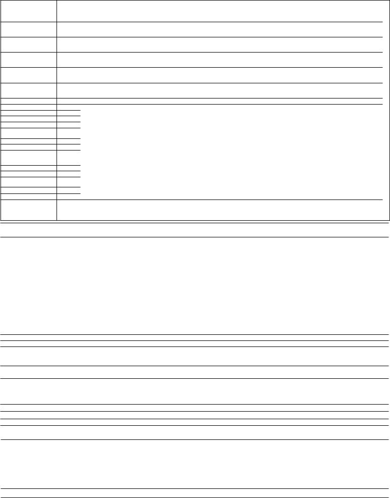
Service Diagnostics Cycle
INTERNAL TIME |
|
|
|
(min:sec) |
0:06 0:01 1:21 1:21 1:21 1:21 0:10 0:40 0:05 0:02 0:13 0:05 1:00 2:00 0:30 1:00 0:30 |
4:00 0:05 0:02 0:05 0:02 1:52 0:06 2:30 1:21 1:21 |
|
TOTAL TIME (MAX): |
|||
|
|
||
23:10 |
|
|
|
SOIL SENSING |
|
|
|
INTERVALS AND |
|
|
|
SENSOR CHECKS |
|
|
|
Thermistor Check |
|
|
|
Intervals (Temperature |
THR |
|
|
Sensor) |
|
||
|
|
||
NOTE 5 |
|
|
4
FOR SERVICE TECHNICIAN’S USE ONLY
INTERNAL TIME (min:sec)
TOTAL TIME (MAX): 23:10
OWI Check Intervals (Optical Soil Sensor)
NOTE 6
NOTE: OWI has thermistor built in (see above).
Diverter Position Sensor CheckNOTE 3
Lower Spray Arm Check (if present)
NOTE 10
Salt Level Reed Switch/Flowmeter Input Test NOTE 11
LOADS Pilot Relay Vent
Fill
Wash Motor
Detergent/Rinse Aid Dispenser
Diverter Diverter Position
Lower Spray Arm Motor (if present).
NOTE 10
Drain Motor Heater
DC Fan Motor (if present) NOTE 7
AC Fan (if present) Regen (if present)
REFERENCE NOTES: See the “Service Diagnostics Cycle Notes” section.
0:06 |
0:01 |
1:21 |
1:21 |
1:21 |
1:21 |
0:10 |
0:40 |
0:05 |
0:02 |
0:13 |
0:05 |
1:00 |
2:00 |
0:30 |
1:00 |
0:30 |
4:00 |
0:05 |
0:02 |
0:05 |
0:02 |
1:52 |
0:06 |
2:30 |
1:21 |
1:21 |
|
|
|
|
|
|
|
|
|
|
|
OWI |
|
|
OWI |
|
|
|
|
|
|
|
|
|
|
|
|
|
|
|
|
|
|
|
|
|
|
|
|
|
DIV |
|
|
|
|
|
|
|
|
|
|
|
|
|
|
|
|
|
|
|
|
|
|
|
|
|
|
|
|
|
|
LSA |
|
|
|
|
|
|
|
|
|
|
|
|
|
|
|
|
|
|
|
|
|
|
|
|
|
|
|
|
|
|
|
|
|
SRM |
|
|
|
|
|
|
|
|
PLT |
PLT |
PLT |
PLT |
PLT |
PLT |
PLT |
PLT |
PLT |
PLT |
PLT |
PLT |
PLT |
PLT |
PLT |
PLT |
PLT |
PLT |
PLT |
PLT |
PLT |
|
|
|
|
|
|
VNT |
VNT |
VNT |
VNT |
VNT |
VNT |
VNT |
VNT |
VNT |
VNT |
VNT |
VNT |
VNT |
VNT |
VNT |
VNT |
VNT |
VNT |
VNT |
|
|
|
|
|
|
|
|
|
FIL |
FIL |
|
FIL |
|
|
|
|
|
|
|
|
|
|
|
|
|
|
|
|
|
|
|
|
|
|
|
|
WSH |
|
WSH |
|
WSH |
WSH |
|
WSH |
WSH |
WSH |
|
|
|
|
|
|
|
|
|
|
|
|
|
|
ErrorCustomer4 |
|
|
|
|
|
|
DSP |
|
|
|
|
|
|
|
|
|
|
|
|
|
|
|
|
ErrorCustomer1 |
ErrorCustomer2 |
ErrorCustomer3 |
|
|
|
|
|
|
|
|
|
|
|
|
|
|
|
|
|
|
|
ErrorService1 |
ErrorService2 |
|
|
|
|
(DIV) |
|
|
|
|
|
DIV |
(DIV) |
|
(DIV) |
(DIV) |
|
|
|
|
|
|
|
||||||
|
|
|
|
|
|
|
|
|
|
|
|
|
|
DRN |
|
DRN |
|
DRN |
DRN |
|
||||||
|
|
|
|
|
|
|
UPR |
UPR |
UPR |
UPR |
UPR |
ON |
ON |
UPR |
UPR |
TZ |
LOW |
LOW |
LOW |
LOW |
LOW |
LOW |
LOW |
|
|
|
|
|
|
|
|
|
|
|
|
|
|
|
|
|
|
|
|
LSA |
|
|
|
|
|
|
|
|
|
|
|
|
|
|
|
|
|
|
|
|
|
|
|
|
|
|
|
|
|
|
|
|
|
|
|
|
|
|
|
|
|
|
|
|
|
|
|
|
|
|
|
|
|
|
|
|
|
|
|
|
|
|
|
|
|
|
|
|
|
|
|
|
|
|
|
|
|
|
|
|
HTR |
|
|
|
|
|
|
HTR |
|
|
|
|
|
|
|
|
|
|
|
|
|
FAN |
|
|
FAN |
FAN |
|
|
|
|
|
|
|
|
FAN |
|
|
|
|
|
|
|
|
|
|
|
|
|
|
|
|
|
|
|
|
|
|
|
|
|
|
|
|
|
|
|
|
|
|
|
|
|
|
|
|
|
|
|
|
|
|
|
|
|
|
|
|
|
FAN |
|
|
|
|
|
|
|
|
|
|
|
|
|
|
|
|
|
|
|
|
|
|
|
|
REG |
|
|
|
|
2 |
8 |
1 |
1 |
1 |
1 |
4 |
3 |
|
9 |
5 |
6 |
6 |
3 |
3, 6 |
|
3 |
3, 10 |
|
|
|
|
|
|
7, 10 |
1 |
1 |
|
|
|
|
|
|
|
|
|
|
|
|
|
|
|
|
|
|
|
|
|
|
|
|
|
|
|
Service Diagnostics Cycle Notes
1To invoke the Service Diagnostics cycle, perform the following while in Standby: ■■ Press START/RESUME to wake up control panel.
■■ Press any three keys in the sequence 1–2–3–1–2–3–1–2–3 with no more than 1 second between key presses. ■■ The Service Diagnostics cycle will start when the door is closed.
■■ To rapid advance one interval at a time, press the START/RESUME key. Rapid advance may skip sensor checks as some checks require two complete intervals.
NOTE: While you are in the Diagnostic Cycle, the Start/Resume feature is turned off (for example, Auto Resume after door interrupts) and the Start/ Resume key becomes an individual advance key.
■■ Invoking Service Diagnostics Cycle clears all status and last run information from memory and restores defaults. It also forces the next cycle to be a sensor calibration cycle.
■■ Drain and wash motors will pulsate on and off. ■■ Last Run cycles and options returned to default.
■■ Last Run Delay returns to the lowest delay increment.
■■ Calibration cycle may force an extra rinse to occur prior to final rinse (to assure clear water), then calibrates the OWI and the fill amount during the final rinse.
■■ A tone will play when Service Error 1 is displayed.
■■ Operating state returns to Standby upon completing or terminating the Service Diagnostics cycle.
2Turn on all LEDs immediately upon receiving entry sequence (even if door is open) and throughout this first interval as a display test.
3Diverter will be on continuously in interval 14. In all other diverter intervals, diverter will only be on until it reaches the intended position for that interval.
4Press HI TEMP key in this interval to clear customer error history.
■■ If Hi Temp key does not respond, the control panel is in Sleep Mode. Open and close the door to wake up the control panel and then press HI TEMP to clear the customer error history.
5Thermistor (temperature sensor) checks - turn clean LED on if thermistor is in its normal temperature range (32°F to 167°F [0°C to 75°C]). Turn sanitized LED on if fill temperature is above 85°F (30°C).
6OWI (optical soil sensor) checks:
■■ Check OWI sensor for the presence of water during the 5-second pause in interval 16 and turn on the Clean LED in interval 15 if water is detected.
■■ Check OWI sensor for presence of bulk soil during pause interval 13 and turn on the Clean LED in interval 12 if bulk soil is detected.
7DC Fan Motor is on during upper rack washing intervals.
8Turn off all LEDs during pause prior to displaying error codes.
9Pause to allow for cold first fill detection.
10■■ Lower spray arm (LSA) models identified by finger-shaped sensor in tub protruding from bottom left side of sump.
■■ Check for LSA motor and sensor during interval 10 according to table below or look for error code F9E4 at end of service cycle.
Interval 10 (4 min lower wash): diagnostic details for LSA models |
|
||
Minute #1: |
Minute #2: |
Minute #3: |
Minute #4: |
LSA rotates CCW |
LSA rotates CW |
LSA rotates CCW |
LSA rotates CW |
LSA motor and sensor status |
indication given during 3rd and |
Clean LED lit to indicate LSA |
Clean LED lit to indicate LSA sensor status good. |
4th minute of interval. |
|
motor status good. |
|
NOTE: Inoperable LSA motor will also cause LSA sensor to indicate bad status. See 9-4 Error Code Table to diagnose.
■■ Interval 3: LSA moves to Home position after drain is completed. Home position = LSA approximately 5° clockwise from 12 o’clock.
11 Sanitized LED turned on in this interval to indicate that the salt level reed switch is closed.
5
 Loading...