

Page 1
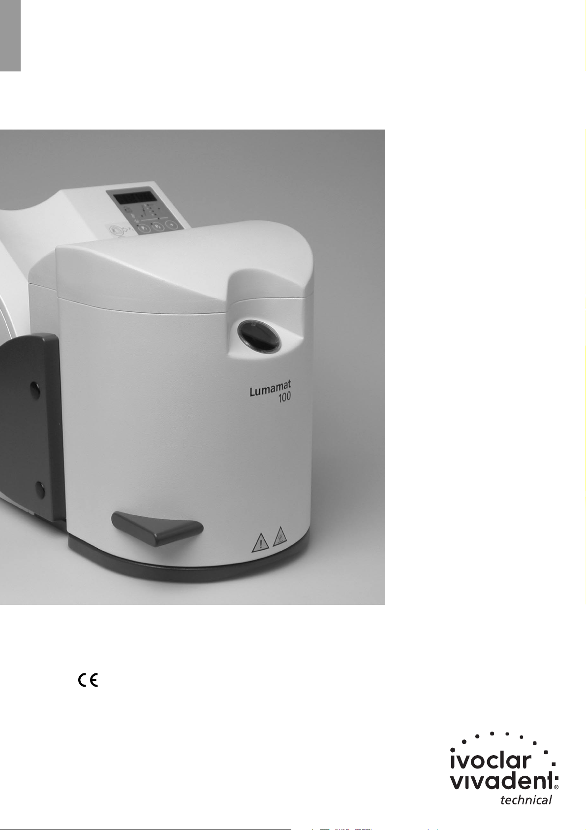
Lumamat
®
100
Operating Instructions
Page 2
2
Page 3

3
Views of the Unit, List of Parts 5
1. Introduction / Signs and Symbols 6
1.1 Preface
1.2 Introduction
1.3 Sings and symbols
2. Safety First 7
2.1 Indications
2.2 Health and safety instructions
3. Product Description 10
3.1 Components
3.2 Hazardous areas and safety equipment
3.3 Functional description
3.4 Contraindication
4. Installation and Initial Start-Up 11
4.1 Unpacking and checking the contents
4.2 Selecting the location
4.3 Assembly and initial start-up
5. Operation 12
5.1 Introduction to the operation
5.2 Working with Program P1
5.3 Working with Program P2
5.4 Working with Program P3
5.5 Working with Program P4
5.6 Acceptable tempering space
6. Practical Use 14
6.1 Switching on/off
6.2 Curing
6.3 Switching the buzzer on/off
6.4 Buzzer upon premature opening during the cooling phase
7. Maintenance, Cleaning, and Diagnosis 15
7.1 Monitoring and Maintenance
7.2 Cleaning
7.3 Changing the lamps
7.4 Changing the dust filter
7.5 Changing the fuse
7.6 Calibration
7.7 Special configuration modes
8. What If… 18
8.1 Technical malfunctions
8.2 Error messages
8.3 Repair
9. Product Specifications 19
9.1 Delivery form
9.2 Technical data
9.3 Acceptable operating conditions
9.4 Acceptable transportation and storage conditions
Table of Contents
Page 4
4
1
36
28
6
5
22
21
17
2
16
26
70
29
72
73
3
4
13
33
20
1
25
7
9
8
10
11
13
32
29
34
23
24
22
75
71
76
77
19
18
27
30
37
26
38
31
39
15
14
12
Page 5
5
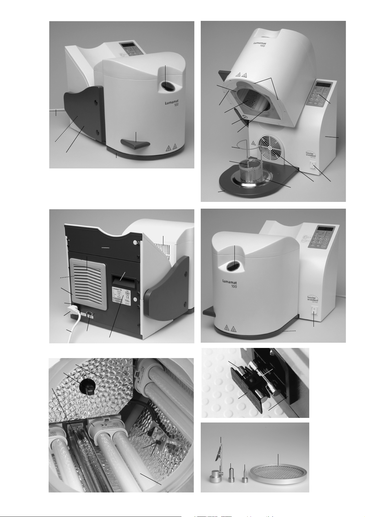
Front view
1Viewing window
2 Curing chamber
3 Grip
4 Bottom of unit
5 Housing
6 Keypad
7 Air vents
8 Filter holder
9 Filter pad
10 Power socket
11 Power plug
12 Fuse
13 Power cord
14 Lateral fuse stop
15 Fuse holder
16 Magnetic catch
17 Lamp protection
18 Lamp
19 Lamp socket
20 Swivel arm
21 Air vent with fan
22 On/Off switch
23 Ventilation grating
24 Rubber feet
25 Rating plate
26 Infrared heater
27 Temperature sensor
28 Sealing
29 Recessed grip
30 Light sensor
31 Upper reflector
32 RS-232 interface
33 Spring for gas pressure
34 Rear panel
36 Screws for lamp protection
37 Sensorprint
38 Temperature protector
39 Extra fuse
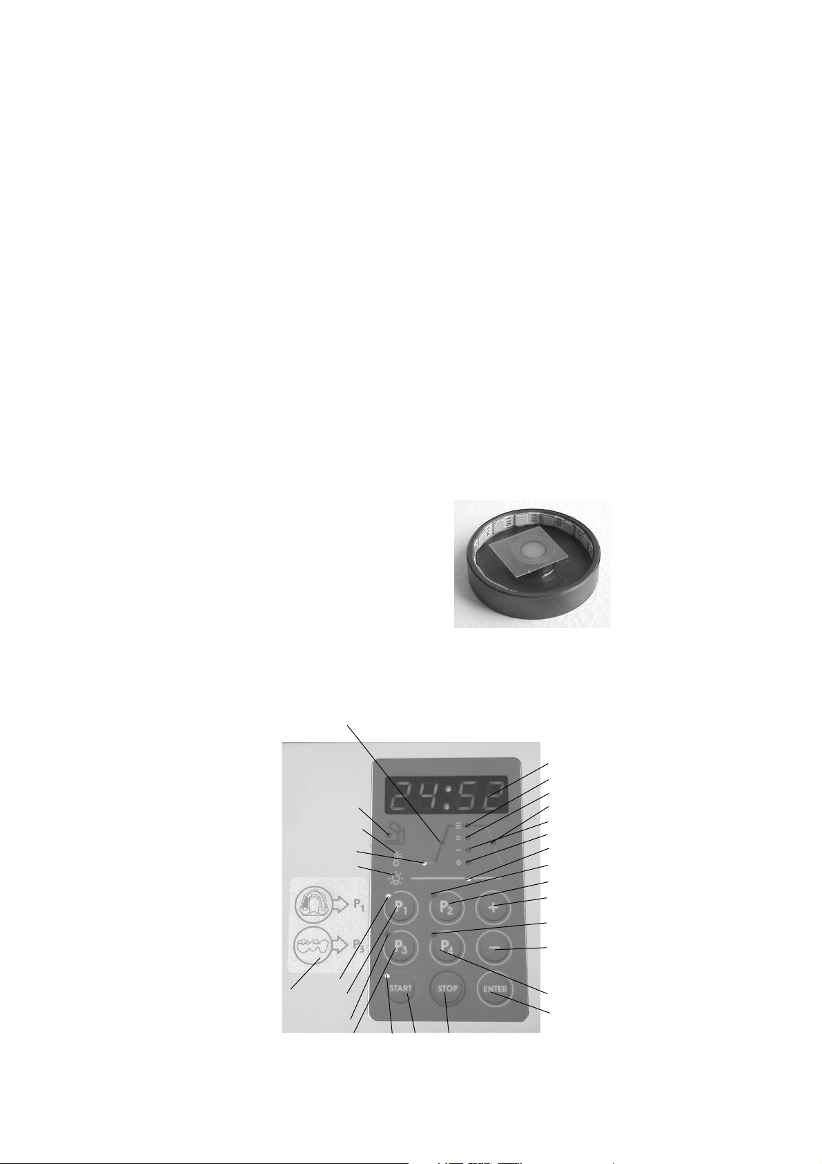
Electronic controls
40 Indicator for opened unit
41 LED P1
42 P1 key
43 LED P3
44 P3 key
45 LED of Start key
46 Start key
47 Stop key
48 Enter key
49 P4 key
50 LED P4
51 - key
52 + key
53 P2 key
54 LED P2
55 Light indicator
56 Heating indicator (off)
57 Heating indicator Stage 1
58 Heating indicator Stage 2
59 Heating indicator Stage 3
60 Display
61 Indicator for heating
procedure
62 Indicator for procuring
63 Indicator for cooling
procedure
64 Symbol for light
65 Symbol for temperature
66 Information plate
Object holder
70 Tempering space limiter
71 Object holder
72 Object holder support
73 Bottom reflector
74 Space limiter grid
75 Alligator clip
76 Object holder small
77 Object holder large
Test set
80 Sample holder
81 Temperature stripe
82 Test material
83 Protection foil
List of Parts
40
41
42
43
44 45 46
47
48
49
51
50
52
53
54
55
56
57
58
59
60
61
65
62
64
63
66
80
Page 6
6
1. Introduction / Signs and Symbols
1.1 Preface
Dear Customer,
Thank you for having purchased
the Lumamat 100.
It is a high quality technical
product. The Lumamat 100 has
been especially developed for
the SR Adoro material from
Ivoclar Vivadent. The integrated
infrared heater permits
tempering of the SR Adoro
material.
The Lumamat 100 has been
designed according to the latest
industry standards. Inappropriate
use may damage equipment and
be harmful to personnel. Please
observe the relevant safety
instructions in Chapter 2.
You must read
these Operating
Instructions!
1.2 Introduction
The Lumamat 100 has been
developed for use in dental lab
technology and is equipped with
state-of-the-art electronic
components.
The Operating Instructions are
divided into several chapters to
help you find specific topics
quickly and easily.
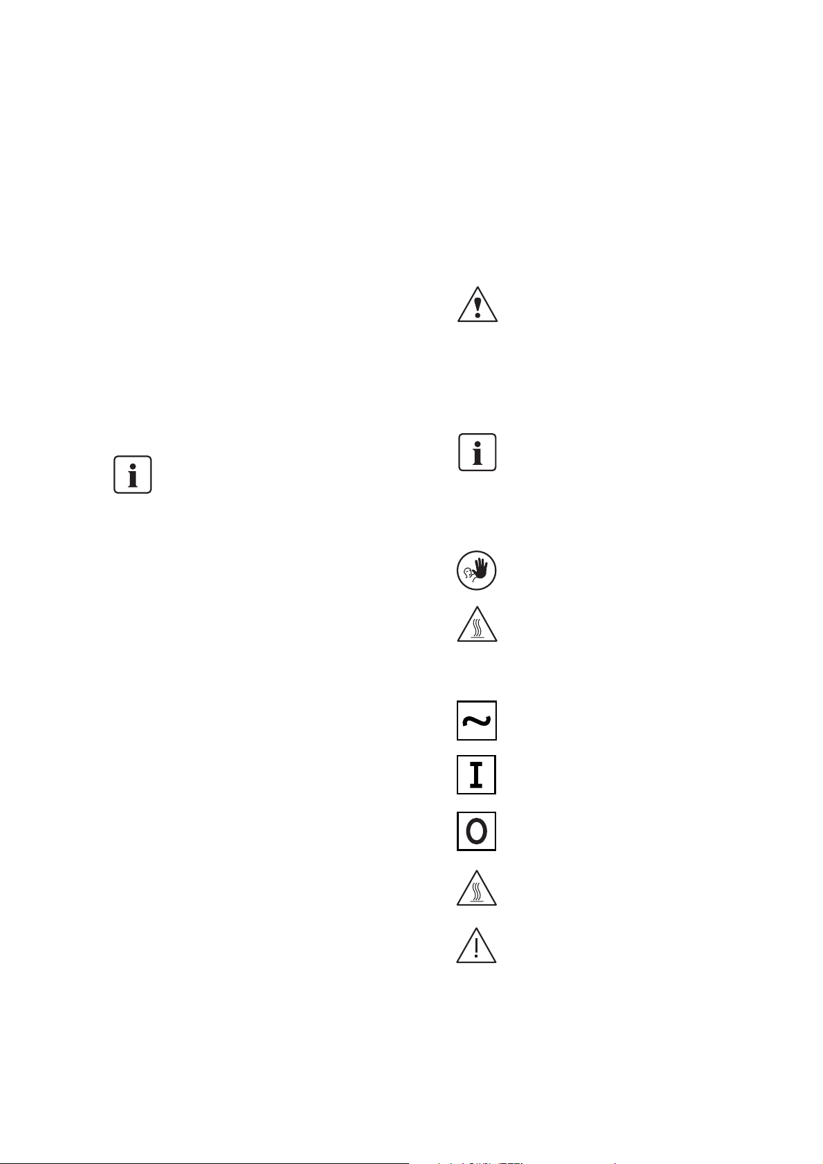
1.3 Signs and symbols
The signs and symbols in these
Operating Instructions and on
the Lumamat 100 facilitate the
finding of important points and
have the following meanings:
Operating Instructions:
Risks and dangers
This symbol marks
safety instructions
that must be
followed to prevent
injury or death.
Furthermore, damage
to the unit and/or
laboratory may thus
be avoided.
Important
information
This symbol marks
additional
information for
correct and economic
use of the
Lumamat 100.
Contraindication
Burn hazard
Unit:
Alternating current
On
Off
Burn hazard
Risk of crushing
Page 7

7
2. Safety First
This chapter is especially important for personnel
who work with the Lumamat 100 or who have to
carry out maintenance or repair work. This chapter
must be read and the corresponding instructions
followed.
2.1 Indications
The Lumamat 100 must only be used to cure and
temper SR Adoro materials and should be used for
this purpose only. Other uses than the one
stipulated are contraindicated. The manufacturer
does not assume any liability for damage resulting
from misuse. The user is solely responsible for any
risk resulting from failure to observe these
Instructions.
Further instructions to assure
proper use of the Lumamat 100:
– The instructions, regulations,
and notes in these Operating
Instructions must be
observed.
- The Lumamat 100 must be
used under the stipulated
environmental and operating
conditions (see Chapter 9).
– The unit must be properly
maintained.
2.1.1
Contraindication
Burn hazard
2.1.2
Contraindication
Risk of crushing
The heater must not be touched,
as there is a burn hazard.
Furthermore, the life cycle of the
heater is considerably shortened
by hand sweat.
The sensorprint must not be
touched for the same reasons.
There is a risk of crushing when
the curing chamber is being
closed. Make sure that the
necessary space is available.
Foreign objects must not be
placed on the air vents. Make
sure that no liquids or other
foreign objects enter the air
vents, since this may result in an
electrical shock.
Please also refer to section
3.2 in Chapter 3.
2.1.3
Risks and dangers
2.1.4
Contraindication
The unit must not be carried by
holding the swivel arm. Carry the
unit only when it is closed. The
recessed grips (29) are located at
the rear panel (34) and in the
front area of the bottom plate.
Page 8

8
2.1.5
Contraindication
Objects must not be placed outside the acceptable tempering
space.
Models that are too high and
thus extend beyond the
tempering space limiter (70)
must not be placed on the
object holder. Furthermore,
thermoplastic model materials
must not be used.
2.1.6
Contraindication
Page 9

9
2.2 Health and safety
instructions
This unit has been designed
according to EN 61010-1 and
has been shipped from the
manufacturer in excellent condition as far as safety regulations
are concerned. To maintain this
condition and to assure risk-free
operation, the user must observe
the notes and warnings
contained in the Operating
Instructions.
– Do not place the unit in the
immediate vicinity of heaters
or other sources of heat.
– Place the apparatus on a fire-
proof table (observe local
regulations, e.g. distance to
combustible objects, etc.).
– Always keep the air vents at
the rear of the apparatus free
from obstruction.
– Make sure that no foreign
objects may enter the air
vents.
– Do not touch any parts that
become hot (lamp, heater)
during the operation of the
unit. There is a burn hazard.
– Clean unit only with a dry or
slightly moist cloth. Do not
use any solvents! Disconnect
power before cleaning.
– Use original packaging for
transportation purposes.
– The user must especially
become familiar with the
warnings and the operating
conditions to prevent injury to
personnel or damage to
materials. The manufacturer is
not responsible for damage
resulting from misuse or failure to observe the Operating
Instructions. Warranty claims
cannot be accepted in such
cases.
– Before switching on, make
sure that the voltage indicated
on the rating plate complies
with your local power supply.
– The power plug may only be
inserted into sockets with
protected contacts.
– Before calibration,
maintenance, repair, or
exchange of parts, the power
must be disconnected if the
unit is to be opened.
– If calibration, maintenance, or
repair has to be carried out
with the power connected
and the unit open, only
qualified personnel, who are
familiar with the risks and
dangers, may perform these
procedures.
– After maintenance, the
required safety tests (high
voltage resistance, protective
conductor test, etc.) have to
be carried out.
– It must be ensured that only
fuses of the indicated type
and rated current are used.
– If it is assumed that safe ope-
ration is no longer possible,
the power must be disconnected to avoid accidental operation. Safe operation is no longer possible if
– the unit is visibly damaged
– the unit does not work
– the unit has been stored
under unfavourable
conditions over an extended
period of time.
– Use only original spare parts.
– The temperature range for
faultless operation is +5 °C to
+40 °C (41–104 °F).
– If the unit has been stored at
very low temperatures or high
atmospheric humidity it has to
be dried or left to adjust to
the room temperature for
approx. 1 hour (do not
connect to power yet).
– Note: Do not work with
liquids near the unit. Should a
liquid accidentally enter the
unit, disconnect power and
consult Customer Service. Do
not operate the unit.
– The unit has been tested for
use at altitudes of up to
2000 m above sea level.
– The unit must be used
indoors.
– Operating the unit without a
dust filter or with a dirty one
influences temperature regulation. Adequate tempering
according to Ivoclar Vivadent
standards is not assured without a dust filter.
Warnings
– Any disruption of the protec-
tive conductor either inside or
outside the unit or any
loosening of the protective
conductor connection may
lead to danger for the user in
case of malfunction. Deliberate interruptions are not
tolerated.
– Direct view into the light or
reflecting surfaces without a
filter is uncomfortable for the
eyes. Prolonged exposure may
lead to eye damage.
Therefore, we recommend
looking at the object only
through the tinted viewing
window of the unit. Protective
goggles absorbing light or
wavelengths below 500 nm
can also be used.
– This is especially applicable for
persons who work with the
unit or in its vicinity for
extended periods of time, or
for people who have undergone eye surgery.
– Persons who are generally
light-sensitive, or who take
medication against lightsensitivity or photo-sensitivity
should not be exposed to the
light of the unit.
– Hot surface. There is a burn
hazard. Do not touch the
heater or the lamps when they
are hot.
– Do not use this unit to cook
food.
– The user is responsible for
cleaning and decontamination
measures, if hazardous
materials spill in the unit or
hazardous gases develop
during operation of the unit
(e.g. incorrect material).
In this case, the user must
contact the local Ivoclar
Vivadent Service Center.
Furthermore, the unit must no
longer be used.
Page 10

10
3. Product Description
3.1 Components
The Lumamat 100 consists of the
following components:
– Base housing with electronic
controls
– Swivel arm with curing
chamber (lamps and heater)
3.2 Hazardous areas and safety
equipment
Description of the hazardous areas:
Risk of burningOuter surfaces of the curing chamber
Risk of eye damageLamp
Risk of electrical shockElectrical components
Risk of crushingOpening / closing mechanism
Risk of burningHeater
Type of riskHazardous area
Description of the safety equipment:
The program is stopped when the apparatus is
opened
Safety switch
Prevents eye damageTinted viewing window
Protection from electrical shockProtective conductor
Protective effectSafety equipment
Also refer to Chapter 2.
3.3 Functional description
The lamp radiates light at 400-580 nm, which
initiates curing of the material. The integrated
heater may be set on three different stages and is
used for tempering the material. Please observe the
recommended values in the Instructions for Use of
the material. The apparatus is thus especially
suitable for tempering the SR Adoro material.
3.4 Contraindication
– Curing of restorations mounted in an articulator.
– Curing of restorations on plaster models heavier
than 400 g
– Curing of restorations on plaster model
exceeding a height of 70 mm
– Curing of restorations on plaster models with a
diameter of more than 80 mm
– Curing of restorations on resin models and
thermoplastic materials
– Curing of temperature sensitive materials
Page 11

11
4. Installation and Initial Start-Up
4.3 Assembly and initial start-up
– Power connection:
Make sure that the voltage indicated on
the rating plate (25) complies with the
local power supply.
Should this not be the case, you must not
connect the unit.
Connect the power cord (13) with the
power socket (10) of the unit and with the
power supply.
–Tempering space limiter (70)
The tempering space limiter is an optical
auxiliary device, defining the acceptable
tempering space for objects, together with
the mounted object holder. These
dimensions must be observed when
placing objects in the curing chamber,
since otherwise parts of the unit will be
damaged.
4.1 Unpacking and checking the
contents
Remove components from their packaging
and place the unit on a suitable table. There
are special transportation grips. The unit is
carried with one hand holding the grip at the
rear of the apparatus and the other hand
supporting the unit at the bottom, where
there is a recessed grip.
Never carry the unit by
holding the swivel arm.
Check the delivery for completeness (see
‘Delivery Form’ in Chapter 9) and transportation damage. If certain parts are missing or
damaged, contact Ivoclar Vivadent Customer
Service. We recommend keeping the original
packaging for future transportation
purposes. Make sure to place the
corresponding transportation safety devices
before transporting the unit.
4.2 Selecting the location
Place the unit on a flat surface using the
rubber feet (24). Make sure it is not placed in
the immediate vicinity of heaters or other
sources of heat. Furthermore, protect the
unit from direct sunlight. Make sure the air
may properly circulate between the wall and
the unit.
Remove the transportation safety
devices from the unit:
1. Safety tape
Check if all lamps are tightly fixed in their
sockets. Push the lamps upwards for that
purpose.
Position the unit in such a way that glare-free
working is ensured and no direct view into
the lamps is possible.
Make sure that there is enough space for the
swivel arm to prevent obstruction of the
swivel mechanism. The unit should neither
be placed nor operated in areas where there
is an explosion hazard.
Initial start-up
The unit may only be switched on or off with
the On/Off switch:
Switched on
Switched off
70
Page 12

12
5. Operating Instructions
5.1 Introduction to the operation
Programs can be selected with P1, P2, P3,
and P4 keys. The respective LED will then be
illuminated.
The parameters are shown in the display. The
program is started by pressing Start. The
display then indicates the remaining time of
the program. The program can be interrupted by pressing Stop.
5.2 Working with Program P1 (set
program with plaster model)
Tempering program for SR Adoro materials
(light/heat), which are polymerized/tempered
on a plaster model (the parameters are set by
the manufacturer and cannot be altered).
If the restorations are placed in the curing
chamber together with a plaster model,
Program P1 must be used (see also sticker on
the apparatus).
When tempering partial models
(e.g. 1/4 models, single or multiple
cores), please refer to the additional instructions in the SR Adoro
Instructions for Use.
5.3 Working with Program P2
(set program)
Light polymerization program for light-curing
resins (light). (The parameters are set by the
manufacturer and cannot be altered).
5.4 Working with Program P3 (set
program without plaster model)
Tempering program for SR Adoro materials
(light/heat), which are polymerized/tempered
without a plaster model (the parameters are
set by the manufacturer and cannot be
altered).
If the restorations are placed in the curing
chamber without the plaster model, Program
P3 must be used (see also sticker on the
apparatus).
5.5 Working with Program P4
(individual program)
The parameters for Program P4 can be set as
desired (see also 6.2.2).
Program Table
No
1
2
3
4
Program
SR Adoro tempering
program (with plaster
model)
Light-curing
program
SR Adoro tempering
program (without
plaster model)
Individual curing
program
VB min
10:00
––––
10:00
0:00 to
10:00***
HP
set
****
––––
set
****
set
****
BP min
––––
10:00
––––
0:00 to
30:00**
VG min
7:00
––––
7:00
0:00 to
30:00***
Stage
3
––––
3
0 – 3
AP min
5:00
****
1:00
****
5:00
****
****
1:00/5:00*
VB
HP
VG
AP
BP
Stage 0
Stage 1
Stage 2
Stage 3
* depending on the heating stage; ** only at stage 0, *** only at stage 1, 2, 3,
**** cannot be set
VB = Precuring, HP = Heating, VG = Tempering, AP = Cooling, BP = Curing
Heat performance:*
Stage 0 = Heater off
Stage 1 = approx. 80 °C / 176 °F
Stage 2 = approx. 95 °C / 203 °F
Stage 3 = approx. 104 °C / 219 °F
* The temperatures were measured with a reference tooth
(typical value) with a plaster model (P1) and without
plaster model (P3).
Page 13

13
5.6 Acceptable tempering space
The parameters (light and temperature)
necessary for adequate curing and
tempering are only ensured within the
acceptable tempering space. The acceptable
tempering space is defined by the tempering
space limiter (70). The objects must be
placed within the acceptable tempering
space.
The necessary parameters (light and
temperature) are only ensured if the
plaster models used meet the following
requirements:
– Lighter than 400 g
– Height below 70 mm
– Diameter smaller than 80 mm
Acceptable tempering space
70
Page 14

14
6. Practical Use
6.1 Switching on/off
Switching on
Put On/Off switch (22) on position 'I'.
Indication of lamp operating hours
After being switched on, the apparatus
performs a brief self-test. During this test,
the display and the LEDs briefly light up.
After that, the display will show four
numbers (e.g. 0823). This means 823 lamp
operating hours. After three seconds, the
indication of the lamp operating hours
changes to the stand-by indication.
Stand-by indication
(- --)
The display shows three dashes and one
empty field. The empty field is moving.
Switching off
Put On/Off switch (22) on position '0'.
6.2 Curing
6.2.1 Standard program
Step 1
Place the object in the curing chamber.
Observe the acceptable tempering space.*
Step 2
Close the unit.
The indicator for opened unit (40) must not
be illuminated as otherwise the program
cannot be started.
Step 3
Select the program by pressing P1 (42), P2
(53), or P3 (44).
Step 4
Press Start (46). Then, the remaining program
time will be indicated on the display.
Step 5
Once the program has been completed,
open the unit and remove the object.
Burn hazard
Please note that the objects may
become very hot. Use tongs or
tweezers to remove the objects.
*
The object must not surpass the
acceptable tempering space. If
this is not observed, the object or
the unit will be damaged when
the unit is closed.
6.2.2 Individual program (P4)
Step 1
Place the object in the curing chamber.
Observe the acceptable tempering space.*
Step 2
Close the unit.
The indicator for opened unit (40) must not
be illuminated as otherwise the program
cannot be started.
Step 3
Select the program.
Press P4 (49). The set parameters will appear
on the display. If changing of the parameters
is not necessary you may proceed with
pressing Start (46). If the parameters have to
be changed, proceed with Step 4.
Step 4
Press Enter (48).
Step 5
Select the heating stage with the '-' or '+'
keys and confirm with Enter. Now the next
parameter to be set starts to blink on the
display. Set the required values for the
individual parameters (observe the values in
the enclosed table) and confirm with Enter.
Now the set parameters light up.
Step 6
Press Start (46) and wait until the program
starts. After that, the remaining program
time will be indicated in the display.
Step 7
Once the program has been completed,
open the unit and remove the object.
Burn hazard
Please note that the objects may
become very hot. Use tongs or
tweezers to remove the objects.
*
The object must not surpass the
acceptable tempering space. If
this is not observed, the object or
the unit will be damaged when
the unit is closed.
6.3 Switching the buzzer on/off
The buzzer can be switched on or off as
desired.
6.3.1 Switching on
To activate the buzzer, proceed as follows:
1. Switch off the unit (put On/Off switch
on position '0')
2. Press Start and hold down the key
3. Put On/Off switch on position 'I'
4. Release Start key
Switching off
To deactivate the buzzer, proceed as
follows:
1. Switch off the unit (put On/Off switch on
position '0'
2. Press Stop and hold down the key
3. Put On/Off switch on position 'I'
4. Release Stop key
6.4 Buzzer upon premature
opening during the cooling
phase
If the chamber is prematurely opened
during the cooling phase, a warning
buzzer sounds. This signal cannot be
acknowledged. As soon as the hood is
closed again, the program (cooling phase)
continues and the buzzer stops.
Wait until the cooling phase (5 min.) has
finished.
On premature interruption of
the program (e.g. power
failure), the curing chamber
must be allowed to cool down
as otherwise the starting
temperature is too high.
Page 15

15
7. Maintenance, Cleaning, and Diagnosis
Item Frequency Cleaning material/measure
Dust filter Monthly Batting or replacing
Housing surfaces If required Cloth
Magnet and counterpiece If required Cloth
Reflector If required Cloth
7.2 Cleaning
The unit may only be
cleaned when it is
cool, since there is
burn hazard. Do not
use any cleaning solutions. The
heater must not be touched, as
hand sweat considerably
shortens the life cycle of the
unit.
What Part Frequency
Check all plug-in connections for correct fit. Power plug Weekly
Check the switch-off mechanism by opening the curing chamber during Interlock Weekly
program operation. If the fan continues to work, the safety switch
(interlock) is defective. In this case, contact your local Ivoclar Vivadent
Service Center.
Check the infrared heater (26) for damage of the glass. Infrared heater (26) Before the first
operation. Weekly
Check temperature and light performance Test Set Every 6 months
This chapter describes the user maintenance
and cleaning procedures. All other tasks
must be performed by qualified service
personnel at a certified Ivoclar Vivadent
Service Center.
7.1 Monitoring and maintenance
The time for these maintenance procedures
depends on the frequency of use and the
working habits of the users. For that
reason, the recommended times are only
approximates.
Disconnect power before maintenance
and cleaning, since there is a risk of
electrical shock.
The following parts have to be cleaned from time to time:
Use only original Ivoclar Vivadent dust
filters.
Page 16

16
7.3 Changing the lamps
The unit is equipped with a sensor that automatically checks the performance of the
lamps. As soon as the performance drops
below a certain value, the display indicates a
corresponding Error message, e.g. Er11,
Er12, Er13. Then, the lamps have to be
replaced.
One defective lamp
For technical reasons, the lamps
are arranged in two groups
consisting of four lamps each.
That means that all four lamps stop working
if one lamp is defective. The defective groups
can be determined by observing the lamps
through the viewing window (1).
Acceptable lamp operating hours
If all eight lamps light up, although Er11 or
Er14 has been displayed, the light
performance is inadequate and the lamps
have reached the end of their life cycle.
Replace all lamps.
Disconnect power during chan-
ging of the lamps and if the unit
has to be opened.
Make sure that the lamp
protection is correctly mounted,
since otherwise the unit cannot
be correctly closed.
Description of how to change the lamps
Step 1
Disconnect power.
Step 2
Remove the eight screws (36) of the lamp
protection.
Step 3
Remove the first lamp of the defective group
from its socket (19) and position the new
one.
Step 4
Close swivel arm with the curing chamber.
Step 5
Connect power.
Step 6
Start Program P2.
Step 7
Look through the viewing window to make
sure that the correct lamp has been replaced.
If all lamps light up, continue with Step 11.
Step 8
If one group of lamps still remains dark,
interrupt the program by pressing Stop.
Step 9
Disconnect power.
Step 10
Repeat Steps 4 to 10 until the defective lamp
has been found.
Step 11
Interrupt program by pressing Stop (47)
Step 12
Disconnect power.
Step 13
Mount the lamp protection (17) with the
corresponding screws (36).
Step 14
Connect power.
36
17
19
18
26
Page 17

17
7.4 Changing the dust filter
Remove filter (8) from the unit with a firm
tug. Clean filter pad (9) or replace it.
Remount the filter..
The unit may only be operated
with the dust filter.
7.5 Changing the fuse
Disconnect power cord (13). The fuse holder
(15) is located in the power socket of the
unit (10). Push the lateral fuse stop (14) in
the direction of the arrow using a screwdriver. The fuse holder (15) is thus released
and may be removed from the unit. Check
fuse (12). Replace defective fuse and insert
the new fuse with its holder into the power
socket (10) until it snaps into place.
Important
Use only fuses with test labels
according to the respective values
specified in ‘Technical Data’
(Chapter 9.2).
9
8
23
7.7 Special configuration modes
With these special modes (functions of the
unit), certain configuration procedures may
be performed and information shown on the
display.
The desired mode is activated as follows:
Press the two keys according to the table
below, while simultaneously switching on the
unit. The display now briefly (3 seconds)
indicates the corresponding mode.
7.6 Calibration
In order to ensure optimum tempering even
after prolonged periods of time, the required
light performance and the corresponding
tempering temperature should be reached.
The temperature sensor of the unit may be
subject to small changes after prolonged use,
which affect the tempering temperature. The
lamps are also subject to a certain aging process, which may compromise the light performance.
These two parameters can be checked any
time by the user with the help of the Test Set
specifically developed for that purpose.
12
15
39
Mode
(Function)
1
2
3
Key Combination
P1 and P2
P3 and P4
START and STOP
Indication on the
Display
The current number of
lamp operating hours is
indicated.
The current calibration
value of the tempering
temperature is indicated.
Within 3 seconds, the 3
software versions of the
unit are indicated one
after the other.
Function
After changing the
lamps, the counter has
to be reset to 0 using
the '-' key.
If the Test Set results
have shown an incorrect
tempering temperature,
the temperature can be
adjusted using key '-'
and '+'. The new
calibration value has to
be confirmed with Enter.
Information about the
software version.
The active mode may only be ended by switching off the unit.
Therefore, we recommend checking the light
performance and tempering temperature
using the Test Set every six months.
The application of the Test Set is described in
the corresponding note accompanying the
Test Set (81). Please observe these
instructions when performing the calibration.
Procedure in case of negative test results:
– If the light performance is inadequate,
change all the lamps.
– If the tempering temperature is
inadequate, adjust the temperature with
the help of the special mode (No. 2).
Please observe the table in Chapter 7.7
for that purpose.
Mode (M)
no meaning
e.g. Mode 2
Page 18

18
8. What if...
8.1 Technical malfunctions
This chapter will help you to recognize
malfunctions and take appropriate measures,
or, if possible, to perform some repairs.
8.2 Error messages
In case of a technical defect, the display will
indicate an Error message with a number.
The Error messages are explained in the
following table:
8.3 Repairs
Repairs may only be carried out by a certified
Ivoclar Service Center. Please refer to the
addresses at the end of these Instructions.
If repairs during the warranty period are not
carried out by a certified Ivoclar Service
Center, the warranty will expire immediately.
Please also read the safety information in
Chapter 2.
Description Double-check Action
Display does not work Is the fuse for the electronic Check fuse.
controls OK?
Display does not work Is the power cord correctly Check power cord for
connected? correct fit
Error Number
10
11
12
14
21
22
23
50
97
98
99
Description
Swivel arm not correctly closed
Light performance too low
No light
Maximum number of acceptable lamp
operating numbers has been surpassed
Temperature in the curing chamber is too
high
Heater does not heat up
Electronics
Possible Causes
Curing chamber does not entirely close (e.g.
something is placed on the bottom of the
unit), or the swivel arm has been opened
during a program in progress (P1).
– At least one lamp is not correctly mounted
in its socket
– At least one lamp per group (group of four)
is defective
– The maximum number of acceptable lamp
operating hours has been surpassed
– Unacceptably high ambient temperature
– Unacceptably low supply voltage
– At least one lamp per group (group of four)
is not correctly mounted in its socket
– At least one lamp per group (group of four)
is defective
– Light sensor or electronic controls defective
Maximum number of acceptable lamp
operating numbers has been surpassed
– Dust filter is dirty
– Air vents are blocked
– Fan is defective
– Unsuitable location of the unit
– Heaters are defective
–Temperature sensor is defective
– Error in the electronic components
Measures
– Remove item
– Do not open the swivel arm during a
program in progress
– Secure lamp correctly in its socket (see Point
7.3)
– Replace defective lamp (see Point 7.3)
– Replace all lamps
– Secure lamp correctly in its socket (see
Point 7.3)
– Replace defective lamp (see Point 7.3)
– Contact your local Ivoclar Vivadent Service
Center
Replace all lamps with new ones (see Point
7.3) and reset the counter for the lamp
operating house to 0 using ‘Mode 1’.
Until the new lamps are available, error message 14 may be acknowledged by pressing
'STOP'. After that, the unit may
temporarily be used again. However, error
message 14 will reappear each time the unit
is switched on to remind the user of the
required lamp replacement.
– Clean dust filter (see Point 7.4)
– Remove obstacle from air vents
– Contact the Service Center
– Select a suitable location (see Point 4.2)
– Contact the Service Center
– Contact the Service Center
–Switch off the unit, wait for 1 minute, and
switch on again
– Contact the Service Center
Page 19

19
9. Product Specifications
Lumamat 100
This chapter contains all the
relevant product specification.
9.1 Delivery form
1 Lumamat 100
1 Power cord
1 Extra fuse
1 Extra lamp
1 Screw driver
1 Operating Instructions
1 Warranty card
1 Standard accessories set
1Test set
Colours:
Standard colour:
White RAL 9016
Special colours:
Salmon RAL 3014
Aquamarine RAL 5014
Turquoise RAL 6027
9.2 Technical data
Power supply
Single-phase alternating current:
220–230 V / 50–60 Hz
100 V / 50–60 Hz
110 V / 50–60 Hz
120 V / 50–60 Hz
Tolerated voltage fluctuations:
+/– 10 %
Power consumption:
max. 750 W
Type of lamp:
Fluorescent lamps (only use
Ivoclar Vivadent lamps)
Electrical fuses:
Value for all voltage versions:
For 220–230 V: T 5A
Has to comply with IEC 127
For 100–120 V: T 8A
Has to be UL and CSA listed.
Dimensions of fuses:
Diameter 5 x 20 mm
Dimensions:
Width: 323 mm
Depth: 440 mm
Height:
closed 272 mm
open 540 mm
Lightwave range:
400–580 nm
Weight:
13.4 Kg
Safety information
This apparatus has been
constructed according to the
following directives:
– Directive 73/336/EEC, low-
voltage guidelines
– Directive 89/336/EEC, radio
protection /electromagnetic
compatibility
Furthermore, the following
standards were observed:
– IEC 61010-1
– UL 3101-1
– CSA 1010.1
9.3 Acceptable operating
conditions
Acceptable temperature range
5–40 °C / 41–104 °F
Acceptable humidity range
Maximum relative humidity at
31 °C (87 °F), gradually
decreasing to 50 % at 35 °C
(95 °F), condensation excluded.
Acceptable ambient pressure
The unit has been tested for use
at altitudes of up to 2000 m
above sea level.
9.4 Acceptable
transportation and
storage conditions
Acceptable temperature range
-30 – +80 °C (-22 – +176 °F)
Acceptable humidity range
Maximum relative humidity at
31 °C (87 °F) gradually decreasing to 50 % at 40 °C (104 °F),
condensation excluded.
Acceptable ambient pressure
500-1060 mbar.
Use only original packaging with
the respective foam material for
shipping purposes.
Page 20

This apparatus has been developed solely for use in
dentistry. Start-up and operation should be carried
out strictly according to the Instructions for Use. Liability cannot be accepted for damages resulting
from misuse or failure to observe the Instructions.
The user is solely responsible for testing the apparatus for its suitability for any purpose not explicitly
stated in the Instructions. Descriptions and data constitute no warranty of attribute and are not binding.
Printed in Liechtenstein
© Ivoclar Vivadent AG, Schaan/Liechtenstein
573351/0303/e
Version: 1
Edition: 03/2003
Ivoclar Vivadent – worldwide
Ivoclar Vivadent AG
Bendererstrasse 2
FL-9494 Schaan
Liechtenstein
Tel. +423 235 35 35
Fax +423 235 33 60
www.ivoclarvivadent.com
Ivoclar Vivadent Pty. Ltd.
1 – 5 Overseas Drive
P. O. Box 367
Noble Park,Vic. 3174
Australia
Tel. +61 3 979 595 99
Fax +61 3 979 596 45
Ivoclar Vivadent Ltda.
Rua Maestro João Gomes de
Araújo 50; Salas 92/94
Sao Paulo, CEP 02332-020
Brasil
Tel. +55 11 69 59 89 77
Fax +55 11 69 71 17 50
Ivoclar Vivadent, Inc.
23 Hannover Drive
St. Catharines, Ont. L2W 1A3
Canada
Tel. +1 800 263 8182
Fax +1 905 988 5411
Ivoclar Vivadent Marketing
Ltd.
Calle 134 No. 13-83, Of. 520
Bogotá
Colombia
Tel. +57 1 627 33 99
Fax +57 1 633 16 63
Ivoclar Vivadent SAS
B.P. 118
F-74410 Saint-Jorioz
France
Tel. +33 450 88 64 00
Fax +33 450 68 91 52
Ivoclar Vivadent GmbH
Dr. Adolf-Schneider-Str. 2
D-73479 Ellwangen, Jagst
Germany
Tel. +49 (0) 79 61 / 8 89-0
Fax +49 (0) 79 61 / 63 26
Ivoclar Vivadent UK Limited
Meridian South
Leicester
LE3 2WY
Great Britain
Tel. +44 116 265 40 55
Fax +44 116 265 40 59
Ivoclar Vivadent s.r.l.
Via dell’Industria 16
I-39025 Naturno (BZ)
Italy
Tel. +39 0473 67 01 11
Fax +39 0473 66 77 80
Ivoclar Vivadent S.A. de C.V.
Av. Mazatlán No. 61, Piso 2
Col. Condesa
06170 México, D.F.
Mexico
Tel. +52 (55) 55 53 00 38
Fax +52 (55) 55 53 14 26
Ivoclar Vivadent Ltd
12 Omega St, Albany
PO Box 5243 Wellesley St
Auckland, New Zealand
Tel. +64 9 630 52 06
Fax +64 9 630 61 48
Ivoclar Vivadent Polska Sp.
z.o.o.
ul. Jana Pawla II 78
PL-01-501 Warszawa
Poland
Tel. +48 22 635 54 96
Fax +48 22 635 54 69
Ivoclar Vivadent S.A.
c/Valderribas 82
E-28007 Madrid
Spain
Tel. +34 91 513 10 08
Fax +34 91 552 64 07
Ivoclar Vivadent AB
Dalvägen 16
S-169 56 Solna
Sweden
Tel. +46 8 514 93 930
Fax +46 8 514 93 940
Ivoclar Vivadent, Inc.
175 Pineview Drive
Amherst, N.Y. 14228
USA
Tel. +1 800 533 6825
Fax +1 716 691 2285
 Loading...