

Page 1
Ivomat IP3
Operating Instructions
Bedienungsanleitung
Mode d’emploi
Istruzioni d’uso
Instrucciones de uso
Instruções de Uso
Page 2

2
Page 3

Ivomat IP3
Table of Contents
1. Introduction / Signs and Symbols
1.1 Preface
1.2 Introduction
1.3 Signs and Symbols
2. Safety First
2.1 Indications
2.2. Health and safety instructions
3. Product Description
3.1 Components
3.2 Functional description
3.3 Hazardous areas and safety equipment
4. Installation
4.1 Unpacking and checking the contents
4.2 Selecting the location
4.3 Connections
4.4 Connecting the return water canister
5. Start-Up
5.1 Switching on/off
5.2 Filling in water
6. Operation
6.1 Placing the objects and starting the program
6.2 End of the program and removing the objects
English
7. Maintenance, Cleaning, and Diagnosis
7.1 Monitoring and maintenance
7.2 Cleaning
7.3 Maintenance
8. What If …
8.1 Power failure
8.2 Repair
8.3 Technical malfunctions
9. Product Specifications
9.1 Delivery form
9.2 Technical data
9.3 Acceptable operating conditions
9.4 Acceptable transportation conditions
3
Page 4

List of Parts
1) Air filter control
1a) Sight glass
1b) Release button
2) Safety lever
3) Bold knob
4) Pressure chamber lid
5) Pressure chamber
6) Thermostat
7) Manometer
8) Timer
9) Mains switch
10) Pilot lamp
11) Non-return valve
12) Compressed air hose
13) Power cord
14) Fuse cap
15) Fuse
16) Safety valve
17) Reset button
18) Water drain hose
19) Canister cap
20) Return water canister
21) Canister hose
22) Sealing washer for sound absorber
23) Sound absorber
24) Collar
25) Air hole
26) Collar screw
27) Polymerization container lid
28) Alligator clips
29) Polymerization container
30) Replenishing cup
4
Page 5

10
2
1
3
4
5
English
9
8
7
27
28
4
3
29
2
5a
5
11
6
30
18
19
21
22
23 20
12
17
1
13
1a
1b
18
14,15
5
16
16a
Page 6
1. Introduction / Signs and Symbols
1.1 Preface
Dear Customer,
Thank you for having purchased the IVOMAT IP3. This
apparatus is a technically advanced product. Please read
these Operating Instructions carefully and use the
IVOMAT IP3 according to the instructions. Should you
have any further questions, please contact your dealer
or Ivoclar Vivadent directly.
1.2 Introduction
Apparatus: IVOMAT IP3
Target group:Dental professionals
The IVOMAT IP3 is suitable for the polymerization of
dental resins.The Operating Instructions ensure safe,
correct, and economic use of the IVOMAT IP3. They are
divided into several, clearly structured chapters.This
should enable you to locate specific topics quickly and
easily.
To inform you about risks, dangers, important
information, and contraindications,these Instructions
contain corresponding signs/symbols to mark important
paragraphs.
We recommend keeping the Instructions in a safe place
near the apparatus to have immediate access to the
information if necessary.
Should you lose the Operating Instructions, extra copies
can be ordered at a normal fee from your local Ivoclar
Vivadent Service Center.
1.3 Signs and symbols
The signs and symbols in these Operating Instructions
facilitate the finding of important points and have the
following meanings:
In the Operating Instructions
Risks and dangers
Information
Contraindication
On the apparatus
Alternating current
On
Off
O
6
Page 7
2. Safety First
English
This chapter is especially important for individuals who
work with the IVOMAT IP3 or who have to carry out
maintenance or repair work. This chapter must be read
and the corresponding instructions followed.
2.1 Indications
The IVOMAT IP3 has been especially developed for the
polymerization of dental resins and materials and should
be used for these purposes only.
Uses other than the ones stipulated are contraindicated.
The manufacturer does not assume any liability for
damage resulting from misuse.The user is solely
responsible for any risk resulting from failure to observe
these instructions.
Further instructions to assure proper use of the furnace:
– The instructions,regulations, and notes in these
Operating Instructions must be observed.
– The apparatus must be operated under the indicated
environmental and operating conditions
(see Chapter 9)
– The IVOMAT IP3 must be properly maintained.
2.2.1
Risks and dangers
2.2.2
Risks and dangers
The housing must not be opened while it is connected to
the power supply,since there is a risk of electrical shock.
The connection cover may only be opened by a qualified
service center.
Make sure that no liquids or other foreign objects enter
the air vents, since this may result in an electrical shock.
7
Page 8
3. Product Description 4. Installation
3.1 Components
The IVOMAT IP3 consists of the following components:
– Apparatus with air filter control
– Non-return valve
– 1.5 m compressed air hose
– 1.2 m water drain hose with canister cap
– Canister hose with sound absorber; polymerization
container in pressure chamber, and 3 object clips
secured to removable lid
– 1 return water container
– 1 replenishing cup
Special accessories
– IVOMAT refill container type IN 1
– Wallfixator
3.2 Functional description
The pressure chamber is equipped with a heater.
In this way, the water can be heated to the temperature
required for the corresponding material.
The pressure chamber is impinged with compressed air
to achieve optimum homogeneity of the material. The
polymerization time can be set by means of the timer.
3.3 Hazardous areas and safety equipment
Description of the hazardous areas:
Hazardous area Type of risk
Safety holder Electrical shock
Air vents Electrical shock
4.1 Unpacking and checking the contents
Remove the apparatus from its packaging and check for
possible transportation damage.We recommend keeping
the original packaging for future transportation
purposes. Use only the original packaging for
transportation.
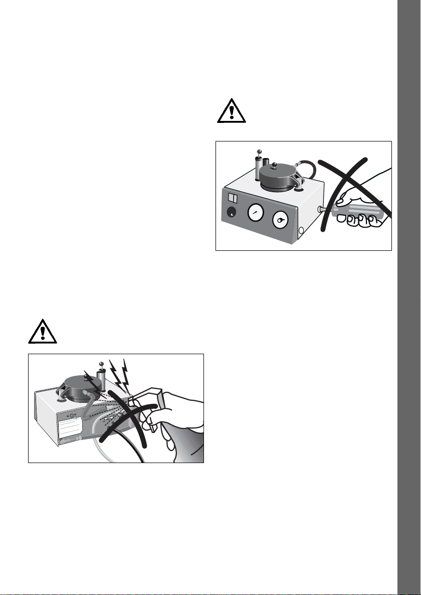
Do not carry the IVOMAT IP3 by means of
the power cord. Support the bottom of the
IVOMAT IP3 with both hands to carry it.
4.2 Selecting the location
Place the apparatus on a flat table using the rubber feet.
Make sure that the apparatus is not placed in the
immediate vicinity of heaters or other sources of heat.
Furthermore, protect the apparatus from direct sunlight.
4.3 Connections
Make sure the voltage indicated on the rating plate
complies with the local power supply.If this is not the
case, the apparatus must not be connected.
Connecting the compressed air hose
Make sure that the hose is properly connected.
Power connection
Make sure that the power cord does not touch any parts
of the apparatus that become hot during use.
The electrical installations of the room where
the apparatus is located must comply with
the national regulations and IEC standards.
Description of the safety equipment
Safety equipment Protective effect
Protective conductor Protection from electrical shock
IP44 (system of protection) Protection from electrical shock
Protective thermal switch Protects the IVOMAT IP3
from overheating
8
Page 9

5. Start-up
English
4.4 Connecting the return water canister
– Fill return water canister (20) to a depth of 3–5 cm.
– Insert the canister hose into the canister and screw
cap on (19).
– Put the canister on the floor in a suitable place.
– Lift the safety lever (2) and engage. Push the bolt to
the right using the knob (3) and lift the lid (4) of the
vessel.
– Remove protective insert used during transportation.
5.1 Switching on / off
Take the polymerization container (29) with lid (27) out
of the pressure chamber. Switch on main (9) (0 to I).The
pilot lamp (10) will light up when the apparatus is ready
for use.
The apparatus may be kept ready for use
throughout the day (mains switch on I), but the
pressure chamber lid (4) should remain either
unbolted or open after each use.
5.2 Filling in water
Fill the pressure chamber with water.
– Maximum filling height: up to the market groove in
the chamber
– Minimum filling height: objects to be polymerized
must be completely under water
9
Page 10
6. Operation
6.1 Placing the objects and starting the program
– Remove the lid (27) from the polymerization contains.
Secure the objects to be polymerized on the alligator
clips (28).
– Slowly insert the polymerization container with lid and
objects, or models held by the Wallfixator,into the
pressure chamber.
– Close chamber lid (4). Bolt the chamber by sliding the
knob (3) to the left. Press safety lever down until it
audibly clicks into place.
Chamber lid
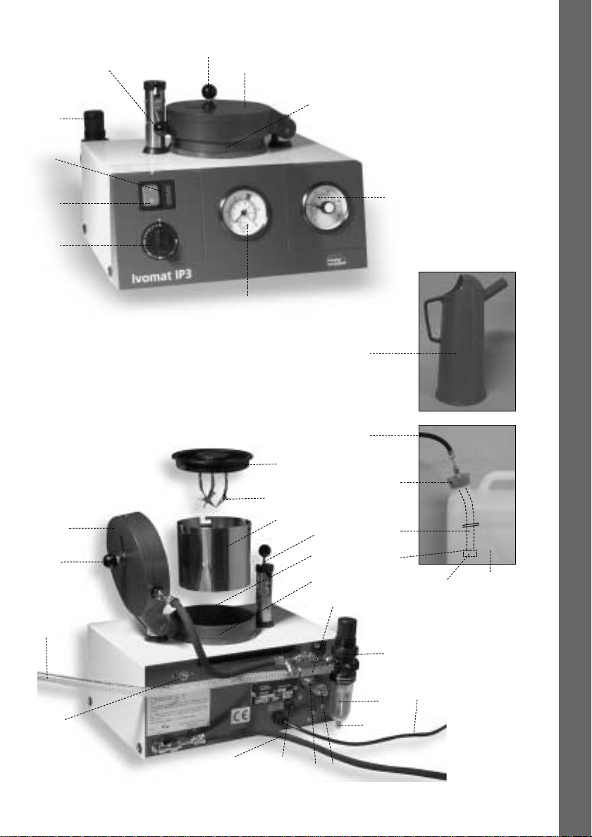
– Set polymerization thermostat (6). Move the red
indicator to the desired temperature.
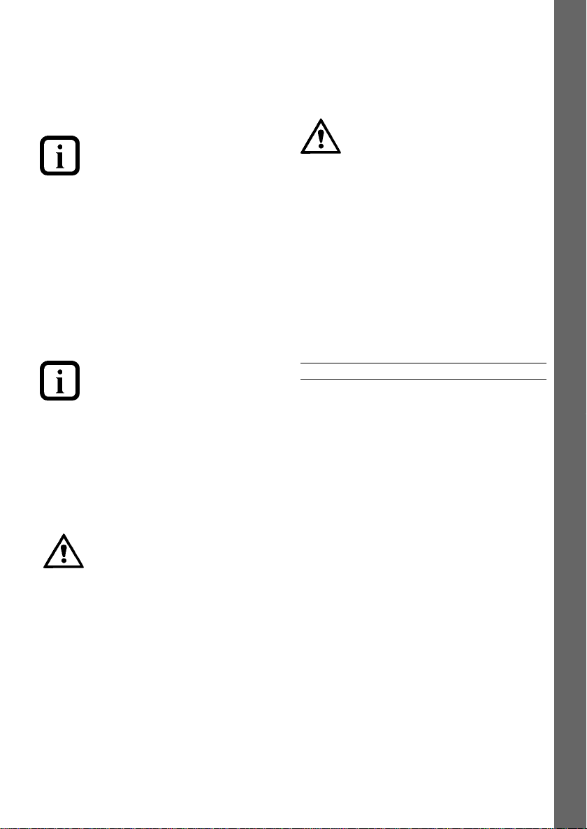
Timer
– Automatic program:
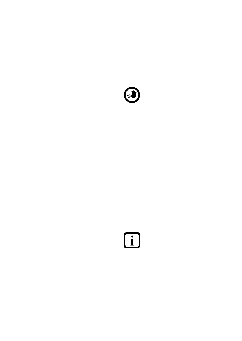
• The manometer (7) indicates the rise in pressure
(check to make sure that the required operating
pressure has been reached by the time the selected
temperature has been achieved.
Thermostat (°C)
The program automatically begins, once the timer
is set. Note: For times under 5 minutes, first turn
the timer to approximately 10 minutes, then
immediately turn it back to the desired time.
(If required, the time may be returned to zero during the
automatic program in progress.The time may also be
prolonged or shortened.)
Manometer
• The water in the pressure chamber is heated.
The black indicator on the thermostat registers the
current temperature.
• Once the desired temperature is reached, the set
polymerization time begins (timer countdown).
• After the polymerization time, the water is ejected
from the pressure chamber and flows into the canister.
At the same time, the pressure is released (indicated
on the manometer).
10
Page 11
7. Maintenance, Cleaning,
and Diagnosis
English
6.2 End of the program and removing the objects
– Opening the pressure chamber lid:
Do not lift the safety lever before the
manometer needle is at zero and the
black thermostat indicator has fallen
below 110 °C (230 °F). (Any residual
pressure is blown off against the chamber
lid.) The lid can then be safely unbolted by
pushing the knob to the right and the
chamber lid opened.
– Removing the polymerized objects:
Remove the polymerization container
including the lid from the pressure
chamber and allow it to cool for a few
minutes before removing the polymerized
objects. Cooling too quickly may result in
stress within the resin materials.
– Use softened water (not distilled) or
water 4–9° hard (70–160 ppm/°
US = 5-12° Brit.) (Ph 7–8/20 °C).
If tape water of more than 9° hard (16° Fr)
is used, special care must be given to
maintenance and cleaning or
decalcification (see decalcification,
page 11).
– Make sure that no wax enters the
pressure chamber.
– Set the polymerization time only after
bolting the pressure chamber lid.
– Caution: Do not touch hot parts of
the apparatus during use.
For safety reasons,disconnect power
cord for all cleaning and maintenance
procedures.
7.1 Monitoring and maintenance
Keep pressure chamber sealing rim (5a) and sealing ring
clean and undamaged. If using water as prescribed in
point IV, remove the perforated plate and clean the
pressure chamber, heater, outflow filter,and outflow
system at least every three months. (Remove any wax
residue using a suitable wax solvent.)
7.2 Cleaning
Dust the IVOMAT IP3 from time to time. Use,for
example, a vacuum cleaner with a cleaning brush for
that purpose.
Parts Cleaning material
Housing Cloth
Pressure chamber Deliming agent
7.3 Maintenance
Please observe the relevant accident control
regulations and other accepted rules regarding
safety and industrial medicine. The connection
cover, which is marked with the rating plate below
may only be opened by a qualified service
technician and with the power disconnected.
Decalcification
If hard tap water of more than 9° (160 ppm/°US = 5–12°
Brit.) is used, the apparatus must be regularly checked,
according to use about once a week, for possible
calcareous deposits on the heating element. For that
purpose, the perforated plate must be removed from the
pressure chamber.
If there is a visible chalky deposit on the heating
element, the device must be cleaned using a deliming
agent as follows: (customary deliming agents used for
coffee makers,boilers, etc. can be used).
11
Page 12

8. What If …
– Fill the pressure chamber with approx. 0.5 l water and
dissolve the amount of deliming agent recommended
in the corresponding instructions for use.
– Close and bolt the pressure chamber lid.
– Set the thermostat to 80 °C and the timer to
5 minutes.
– Once the program is completed, open the lid and
check the cleaning results.
– Remove any large, loose particles from the chamber.
– If necessary,repeat the procedure until the heating
element and pressure chamber are clean.
– After decalcifying, repeat the procedure with fresh
water to rinse the pressure chamber and the outflow
system. (Once the operating pressure is reached, the
program can be interrupted by setting the timer to 0)
– Empty the return water canister and rinse with fresh
water.
Deliming agents are caustic and toxic.
Avoid contact with skin and eyes. In case
of accidental contact, rinse with copious
amounts of fresh water.
Condensation accumulated in the sight glass (1a) can be
drained off by pushing the release button (1b).
At three-months intervals, unscrew the canister cap (19)
and clean (clear) the small air hole (25) of the canister
hose (21). Access to the hole (25) is gained by loosening
the screw (26) and removing the collar (24).
8.1 Power failure or blown fuse
– In the event of a power failure, the automatic program
is interrupted. Once the power supply returns,the
program will automatically continue.
– To take the objects out of the pressure chamber
during prolonged power failures, proceed as described
under 3a.
– If the fuse (15) of the apparatus is defective, open the
fuse cap and replace the fuse.
If problems arise, which are not mentioned in the
table below, please contact our Customer Service
Department.
8.2 Repair
Repairs may only be carried out by a certified Ivoclar
Vivadent Service Center. Please contact our Customer
Service Department.
12
Page 13

8.3 Technical malfunctions
English
Error or malfunction
1. Objects not fully cured, even though
the program ran normally (Timer
has run to "0", manometer shows
"0").
2. Program fails to continue after
polymerization time has been set.
3. Automatic program has stopped
too soon (Timer has not run to "0",
manometer indicates pressure).
Possible causes
– Too little water in the
pressure chamber, or
– temperature too low,or
– time too short, or
– air pressure too low
Chamber lid not properly closed
and bolted.
No or far to little water in the
pressure chamber (excess heat
protection of the heater
engaged).
Heater and overheating sensor
in the chamber very dirty or
calcareous.
Power failure or defective fuse.
Corrective action
1a) Repeat program (polymerization) with
sufficient water, correct temperature and
time, and stipulated air pressure.
2a) Close and bolt chamber lid according
to the instructions.
3a) Disconnect power. Release pressure by
means of the safety valve.Turn air knob
(16a) at the end of the safety valve (16)
counter-clockwise until the manometer
indicates "0" and the black needle on the
thermostat registers less than 90 °C/194 °F.
Open the chamber lid and allow chamber
to cool for approx. 6 min.Then, turn air
knob clockwise until it stops. Press red
reset button (17) on the back of the
apparatus.
3b) Proceed as described in 3a). Remove
perforated plate from the pressure
chamber and clean it. Clean heater with
overheating sensor and clean or delime the
chamber according to the service
recommendations.
3c) See point 7.
4. Pressure falls abnormally slowly
after the end of the program.
(Manometer shows "0", timer has
run to "0". Polymerization
temperature has been reached.
Outflow filter in the pressure
chamber is partly blocked.
Outflow system partly blocked.
13
4a) Remove perforated plate from the
pressure chamber. Clean outflow filter,
chamber, and heater, or delime according
to the service recommendations.
4b) Clean sound absorber (23). Unscrew
water drain hose (18) from the back of the
apparatus and blow compressed air
through the hoses. Delime if necessary.
Page 14

9. Product Specifications
9.1 Delivery form
The IVOMAT IP3 consists of the following components:
– Apparatus with air filter control
– Non-return valve
– 1.5 m compressed air hose
– 1.2 m water drain hose with canister cap
– Canister hose with sound absorber; polymerization
container in pressure chamber, and 3 object clips
secured to removable lid
– 1 return water container
– 1 replenishing cup
9.2 Technical data
Power supply: Single-phase alternating current
Standard version:
– 220 V / 50 Hz
– 240 V / 50 Hz
Acceptable voltage fluctuations: +10 % to –15 %
Power consumption: 1030 W
Electrical fuses:
100–118 V: 12.5 A, slow. Diameter: 6.3 x 32 mm
220 V: 6.3 A, slow. Diameter: 5 x 20 mm
240 V: 5 A, slow. Diameter 5 x 20 mm
Compressed air:
Operating pressure (already set): approx. 6 bar = 6.10 Pa
(Tolerance:green area of the scale)
System pressure: 6 to max. 12 bar = 6 to max.12.10 Pa
Hose with an inside diameter of 6 mm
9.3 Acceptable operating conditions
Acceptable temperature range
+5 °C to +40 °C (+41 °F to +104 °F)
Acceptable altitude:
The apparatus has been tested for use at altitudes of up
to 2000 m
Atmospheric pressure of 500 mbar to 1060 mbar
9.4 Acceptable transportation and storage
conditions
Acceptable temperature range
–20 °C to +55 °C (-4 °F to +131 °F)
Maximum relative humidity: 80 %
Dimensions of the closed apparatus:
Width: 312 mm, Depth:302 mm
Height: 220 mm
Useful dimensions of pressure chamber:
Diameter: 112 mm, height:98 mm
Max. water capacity 0.78 dm
Weight: 9.75 kg
Safety information:
EN 61010, Part 1, EMC tested
3
(Liter)
14
Page 15

Ivomat IP3
Teileverzeichnis
1. Einleitung und Zeichenerklärung
1.1 Vorwort
1.2 Einleitung
1.3 Zeichenerklärung
2. Sicherheit geht vor
2.1 Bestimmungsgemässe Verwendung
2.2 Sicherheits- und Gefahrenhinweise
3. Produktbeschreibung
3.1 Aufbau des Gerätes
3.2 Funktionsbeschreibung
3.3 Gefahrenstellen und Sicherheitseinrichtungen
4. Installation
4.1 Auspacken und Lieferumfang prüfen
4.2 Standortwahl
4.3 Anschlüsse herstellen
4.4 Rückwasser Kanister anschliessen
5. Inbetriebnahme
5.1 Ein- und Ausschalten des Gerätes
5.2 Wasser einfüllen
6. Bedienung
6.1 Bestückung und Programmstart
6.2 Programmende und Objekt entnehmen
Deutsch
7. Unterhalt, Reinigung und Diagnose
7.1 Kontroll- und Unterhaltsarbeiten
7.2 Reinigungsarbeiten
7.3 Wartungshinweise
8. Was ist, wenn …
8.1 Stromausfall
8.2 Reparaturarbeiten
8.3 Technische Störungen
9. Produktspezifikationen
9.1 Lieferform
9.2 Technische Daten
9.3 Zulässige Betriebsbedingungen
9.4 Zulässige Transportbedingungen
15
Page 16

Teileverzeichnis
1) Luftfilterregler
1a) Sichtbehälter
1b) Ablassknopf
2) Nockenhebel
3) Knopf für Riegelbetätigung
4) Kesseldeckel
5) Druckkessel
5a) Druckkessel-Dichtungsrand
6) Temperaturregler
7) Manometer
8) Zeitschaltuhr
9) Netzschalter
10) Kontrollampe
11) Rückschlagventil
12) Druckluftschlauch
13) Netzkabel
14) Verschlusskappe zu Sicherung
15) Sicherung
16) Sicherheitsventil
16a) Anlüftung des Sicherheitsventils
17) Rückstellknopf
18) Abwasserschlauch
19) Kanisterdeckel
20) Rückwasserkanister
21) Kanisterschlauch
22) Dichtscheibe für Schalldämpfer
23) Schalldämpfer
24) Ring
25) Belüftungsbohrung
26) Schraube
27) Deckel des Polymerisationsbehälters
28) Krokodilklemme
29) Polymerisationsbehälter
30) Wasser-Einfüllgefäss
16
Page 17
10
2
3
4
Deutsch
5
1
9
8
7
27
28
4
3
29
2
5a
5
11
6
30
18
19
21
22
23 20
12
17
1
13
1a
1b
18
14,15
17
16
16a
Page 18

1. Einleitung und Zeichenerklärung
1.1 Vorwort
Sehr geehrter Kunde,
Es freut uns, dass Sie sich für den Kauf des IVOMAT IP3
entschieden haben. Bei diesem Gerät handelt es sich um
ein technisch hochstehendes Produkt. Wir bitten Sie, die
Bedienungsanleitung zu lesen und das Gerät analog der
Bedienungsanleitung in Betrieb zu nehmen. Wenn Sie
noch zusätzliche Fragen haben, wenden Sie sich bitte an
das entsprechende Depot oder direkt an Ivoclar Vivadent.
1.2 Einleitung
Zutreffendes Gerät: IVOMAT IP3
Zielgruppe: Zahntechnisches Fachpersonal
Der IVOMAT IP3 eignet sich für das Aushärten von
Dental-Kunststoffen. Die Bedienungsanleitung dient zur
sicheren, sachgerechten und wirtschaftlichen Nutzung
des IVOMAT IP3. Die Bedienungsanleitung ist in mehrere
Kapitel unterteilt, die klar gegliedert sind. Diese
Aufteilung erleichtert ein schnelles Auffinden der
gewünschten Punkte.
Um Sie schnell und übersichtlich über Gefahren, wichtige
Informationen und nicht zulässige Anwendungen
informieren zu können, werden an den Stellen
entsprechende Symbole (Piktogramme) verwendet.
Wir empfehlen Ihnen, die Bedienungsanleitung an einem
geschützten Ort in der Nähe des Gerätes aufzubewahren,
sodass jederzeit ein schneller Informationszugriff möglich
ist. Bei einem eventuellen Verlust können Sie die BA
gegen Schutzgebühr über die entsprechende Ivoclar
Vivadent Servicestelle beziehen.
1.3 Zeichenerklärung
Die Symbole in der Bedienungsanleitung erleichtern
Ihnen das Auffinden wichtiger Punkte und geben Ihnen
folgende Hinweise:
In der Bedienungsanleitung:
Gefahren mit Risiken
Informationen
Nicht zulässige Verwendungen
Auf dem Gerät:
Wechselstrom
Ein
Aus
O
18
Page 19

2. Sicherheit geht vor
Deutsch
Dieses Kapitel ist für alle Personen, die mit dem Gerät
arbeiten oder am Gerät Unterhalts- oder Reinigungsarbeiten durchführen, zwingend zu lesen. Die Hinweise
sind zu befolgen.
2.1 Bestimmungsgemässe Verwendung
Der IVOMAT IP3 ist speziell für die Aushärtung von
Dental-Kunststoffen und Materialien entwickelt worden.
Bitte verwenden Sie dieses Gerät ausschliesslich für
diesen Zweck.
Eine andere oder darüber hinausgehende Benutzung gilt
als nicht bestimmungsgemäss. Für hieraus resultierende
Schäden haftet der Hersteller nicht. Das Risiko trägt
allein der Anwender.
Zur bestimmungsgemässen Anwendung gehören zudem:
– Die Beachtung der Anweisungen,Vorschriften und
Hinweise in der vorliegenden Bedienungsanleitung
– Der Betrieb unter den vorgeschriebenen Umwelt- und
Betriebsbedingungen (siehe Kapitel 9)
– Die korrekte Instandhaltung des Gerätes
2.2.1
Gefahren und Risiken
2.2.2
Gefahren und Risiken
Das Gehäuse darf wegen Stromschlaggefahr nicht
geöffnet werden, wenn das Gerät unter Stromspannung
steht. Den Anschlussdeckel darf nur eine qualifizierte
Servicestelle öffnen.
Es dürfen keine Gegenstände oder Flüssigkeiten in die
Lüftungsschlitze gelangen. Es könnte dadurch Stromschlag verursacht werden.
19
Page 20
3. Produktbeschreibung
4. Installation
3.1 Aufbau des Gerätes
Der IVOMAT IP3 besteht aus folgenden Komponenten:
– Gerät mit Luftfilterregler
– Rückschlagventil
– 1,5 m Druckluft-Schlauch
– 1,2 m Abwasserschlauch mit Kanisterdeckel
– Kanisterschlauch und Schalldämpfer, im Druckkessel
eingesetztem Polymerisationsbehälter mit 3, am
abnehmbaren Deckel befestigten, Objektklemmen.
– 1 Rückwasserkanister
– 1 Wasser-Einfüllgefäss
Sonderzubehör:
– IVOMAT-Nachfüllanlage Typ IN 1
– Wallfixator
3.2 Funktionsbeschreibung
Der Druckbehälter ist mit einer Heizung versehen. Somit
kann das Wasser je nach Bedarf auf die entsprechende
Temperatur aufgeheizt werden,welche für das Material
benötigt wird. Der Drucktopf wird mit Pressluft
beaufschlagt, um eine optimale Materialhomogenität zu
erzielen. Die Aushärtedauer kann mittels dem
Zeitschalter eingestellt werden.
3.3 Gefahrenstellen und Sicherheitseinrichtungen
Bezeichnung der Gefahrenstellen
Gefahrenstelle Art der Gefährdung
Sicherheitshalter Stromschlag
Lüftungsschlitze Stromschlag
Bezeichnung der Sicherheitseinrichtungen
Sicherheitseinrichtung Schutzwirkung
Schutzleiter Schutz vor Stromschlag
IP44 (Schutzart) Schutz vor Stromschlag
Thermoschutzschalter Schützt den IVOMAT IP3 vor
Überhitzung
4.1 Auspacken und Lieferumfang prüfen
Gerät aus der Verpackung nehmen und auf eventuelle
Transportschäden überprüfen.Wir empfehlen, dass Sie
die Originalverpackung für eventuelle Versandzwecke
aufbewahren. Für den Versand verwenden Sie bitte nur
die Originalverpackung.
Tragen Sie den IVOMAT IP3 nicht am
Netzkabel. Tragen Sie den IVOMAT IP3 mit
beiden Händen am Geräte-Unterteil.
4.2 Standortwahl
Stellen Sie das Gerät mit den Gummifüssen auf eine
ebene Ablagefläche. Achten Sie darauf, dass das Gerät
nicht einer direkten Sonnenbestrahlung ausgesetzt ist.
Stellen Sie das Gerät nicht in unmittelbare Nähe von
Heizkörpern oder anderen Wärmequellen.
4.3 Anschlüsse herstellen
Typenschild mit Spannung überprüfen.
Bitte prüfen Sie, ob die auf dem Typenschild angegebene
Spannung mit derjenigen Ihres Netzes übereinstimmt.
Sollte dies nicht der Fall sein, darf das Gerät nicht
angeschlossen werden.
Druckschlauch anschliessen
Bitte prüfen Sie, ob der Schlauch einwandfrei aufgesteckt
ist
Netzanschluss herstellen
Es ist zu beachten, dass das Netzkabel nicht mit heiss
werdenden Geräteteilen in Berührung kommt.
Die elektrischen Installationen des Raumes, in
dem sich das Gerät befindet, müssen den
landesüblichen und den IEC Normen
entsprechen.
20
Page 21

5. Inbetriebnahme
Deutsch
4.4 Rückwasser Kanister anschliessen
– Rückwasserkanister (20) 3–5 cm mit Wasser füllen.
– Kanisterschlauch in Kanister stecken und
Kanisterdeckel (19) verschrauben
– Rückwasserkanister auf dem Boden an geeigneter
Stelle aufstellen.
– Nockenhebel (2) nach oben schwenken und einrasten,
Riegel mit Knopf (3) nach rechts schieben und
Kesseldeckel (4) aufklappen.
– Einlage (Transportschutz) entfernen.
5.1 Ein- und Ausschalten des Gerätes
Polymerisationsbehälter (29) mit Deckel (27) aus Druckkessel nehmen. Netzschalter (9) drücken (von Pos. 0 auf
Pos.I). Die leuchtende Kontrollampe (10) zeigt die
Betriebsbereitschaft des Gerätes an.
Das Gerät kann den ganzen Arbeitstag in Betriebsbereitschaft gehalten werden (Netzschalter I ),
jedoch sollte nach jedem Arbeitszyklus der Kesseldeckel (4) offen oder unverriegelt bleiben.
5.2 Wasser einfüllen
Wasser in den Druckkessel einfüllen:
– Füllhöhe maximal = bis zur Markierungsrille des
Druckkessels
– Füllhöhe minimal = Objekte müssen vollständig im
Wasser sein.
21
Page 22

6. Bedienung
6.1 Bestückung und Programmstart
– Deckel (27) vom Polymerisationsbehälter abnehmen,
Polymerisationsgut an den Krokodilklemmen (28)
befestigen.
– Polymerisationsbehälter mit Deckel und Objekten,
bzw.Modelle mit dem Wallfixator,in den Druckkessel
langsam einsetzen.
– Kesseldeckel (4) schliessen:Riegel mit Knopf (3) nach
links schieben und Nockenhebel (2) nach unten
drücken bis Einrasten hörbar.
3
4
2
Kesseldeckel
– Polymerisationstemperatur am Temperaturregler (6) –
roter Sollwert-Zeiger – einstellen.
8
Zeitschaltuhr
– Automatischer Programmablauf:
• Das Manometer (7) zeigt den Druckaufbau an.
(Prüfen, ob der erforderliche Betriebsdruck nach
Erreichen der Soll-Wert-Temperatur erreicht wird.)
6
Temperatur-Regler (°C)
Nach dem Einstellen beginnt der automatische
Programmablauf. Beachten: Bei Zeiten unter
5 Minuten zuerst auf ca. 10 Minuten «überzeihen» und sogleich auf die gewünschte Zeit
rückstellen! (Falls erforderlich, kann die Zeit während
des automatischen Programmablaufs auf Null
geschaltet, verlängert oder verkürzt werden.)
7
Druckanzeige
• Wasser im Druckkessel wird aufgeheizt
(kontrollierbar am schwarzen Ist-Wert-Zeiger des
Temperaturreglers.)
• Nach Erreichen der Soll-Wert-Temperatur läuft die
eingestellte Polymerisationszeit ab.(Zeitschaltuhr
rückwärtszählend)
• Nach Ablauf der Polymerisationszeit wird das
Wasser aus dem Druckkessel in den Rückwasserkanister befördert. Zugleich erfolgt der Abbau des
Druckes (Manometer-Anzeige).
22
Page 23

7. Unterhalt, Reinigung
und Diagnose
Deutsch
6.2 Programmende und Objekt entnehmen
– Öffnen des Druckkesseldeckels:
Erst wenn der Zeiger des Manometers
auf Null steht und der schwarze IstWert-Zeiger des Temperaturreglers
unter 110°C abgelaufen ist, darf der
Nockenhebel (2) nach oben geschwenkt werden. (Eventuell im Gerät
noch vorhandener Restdruck wird auf die
Geräteabdeckung abgeblasen.) Nun kann
der Riegel mit Knopf (3) gefahrlos nach
rechts geschoben und der Kesseldeckel
aufgeklappt werden.
– Entnahme des Polymerisationsgutes:
Polymerisationsbehälter samt Deckel aus
dem Druckkessel nehmen und vor Entnahme des Polymerisationsgutes einige
Minuten abkühlen lassen. Bei zu schnellem
Abkühlen können im Kunststoff
Spannungen entstehen.
– Enthärtetes Wasser (kein destilliertes)
oder Wasser mit 4 bis 9° d-Härte (7 bis
16° fr) verwenden. (Ph 7 bis 8 / 20° C).
Bei Verwendung von Leitungswasser mit
über 9° d-Härte (16° fr) ist besondere
Wartung – Reinigung, bzw. Entkalkung
erfolderlich! (Siehe Entkalkung, Seite 23).
– Dafür sorgen, dass möglichst kein
Wachs in den Druckkessel gelangt.
– Polymerisationszeit an der
Zeitschaltuhr erst nach Verriegelung
des Kesseldeckels einstellen!
– Vorsicht: Bei der Bedienung des
Gerätes sind heisse Teile berührbar!
Aus sicherheitstechnischen Gründen bei
sämtlichen Wartungs- und Reinigungsarbeiten
den Netzstecker aus der Gerätesteckdose
ziehen.
7.1 Kontroll- und Unterhaltsarbeiten
Druckkessel-Dichtungsrand (5a) und Kesseldichtung
sauber halten und nicht beschädigen. Bei Verwendung
von Wasser, wie unter Punkt 6.2 vorgeschrieben, mindestens vierteljährlich Druckkessel, Heizung,Ablauffilter und
Ablaufsystem nach Herausnehmen des gelochten
Zwischenbodens reinigen. (Wachsrückstände mit
geeigneten Wachslösemitteln entfernen.)
7.2 Reinigungsarbeiten
Den IVOMAT IP3 gelegentlich von Staub befreien.
Verwenden Sie dazu zum Beispiel einen Staubsauger mit
Reinigungspinsel.
Was Womit
Gehäuse Lappen
Drucktopf Entkalkungsmittel
7.3 Wartungshinweise
Beachten Sie bitte die einschlägigen Unfallverhütungs-Vorschriften sowie die sonstigen anerkannten sicherheitstechnischen und arbeitsmedizinischen Regeln. Der Anschlussdeckel,
welcher mit dem untenstehenden Hinweisschild
gekennzeichnet ist, darf nur nach Ziehen des
Netzsteckers (Unterbrechen der Spannungsversorung) vom qualifizierten Servicetechniker geöffnet
werden.
Entkalkung
Wird Leitungswasser mit über 9° d-Härte (16° fr)
verwendet, so muss das Gerät je nach Inanspruchnahme
regelmässig, z.B. wöchentlich, auf eventuelle Kalkablagerungen am Heizkörper überprüft werden! Um dies
festzustellen, muss der Lochblech-Zwischenboden aus
dem Druckkessel entfernt werden.
Hat sich am Heizkörper eine sichtbare Kalkschicht gebildet, muss das Gerät mit einem kalklösenden Mittel
folgendermassen gereinigt werden: (Geeignet sind
handelsübliche Kalkentferner, wie sie zum Entkalken von
Kaffeemaschinen, Boilern etc. verwendet werden.)
23
Page 24

8. Was ist, wenn …
– Ca. 0,5 Liter Wasser in den Druckkessel füllen und die
in der Gebrauchsanweisung des Kalkentferners
empfohlene Menge des Mittels darin auflösen.
– Kesseldeckel schliessen und verriegeln.
– Temperaturregler auf 80° C einstellen.
– Zeitschaltuhr auf 5 Minuten einstellen.
– Nach Beendigung des Programmablaufes Kesseldeckel
öffnen und sich vom Ergebnis der Entkalkung
überzeugen.
– Grobe, abgelöste Kalkpartikel aus dem Druckkessel
entfernen.
– Erforderlichenfalls Entkalkungsvorgang wiederholen,
bis Heizung und Druckkessel sauber sind.
– Nach beendeter Entkalkung Vorgang mit reinem
Wasser durchführen, damit der Druckkessel und das
Ablaufsystem gespült werden. (Ist der Betriebsdruck
erreicht, kann das Programm durch Stellen der
Zeitschaltuhr auf 0 abgebrochen werden.)
– Rückwasserkanister entleeren und mit sauberem
Wasser ausspülen.
Entkalkungsmittel sind ätzend und giftig!
Haut- und Augenkontakt vermeiden!
Bei versehentlichem Kontakt mit viel
Frischwasser spülen!
Im Sichtbehälter (1a) des Luftfilterreglers angesammeltes
Kondensat durch Drücken des Knopfes (1b) ablassen.
Vierteljährlich nach Abschrauben des Kanisterdeckels
(19) kleine Belüftungsbohrung (25) am Anschlussrohr des
Kanisterschlauches (21) säubern (freimachen). Die
Bohrung (25) wird zugänglich nach Lösen der Schraube
(26) und Abziehen des Ringes (24).
8.1 Stromausfall vom Netz her oder infolge
Sicherungsdefekt:
– Bei Stromausfall wird der automatische
Programmablauf unterbrochen. Nach Beendigung der
Störung läuft das Programm automatisch weiter.
– Sofern man bei längeren Stromunterbrechungen die
Objekte aus dem Druckkessel nehmen will, ist wie
unter 3a) beschrieben, vorzugehen.
– Ist die Sicherung (15) des Gerätes defekt, so kann
diese nach Öffnen der Verschlusskappe (14) entfernt
und ersetzt werden.
Bei Fehlern oder Störungen, die in der vorstehenden Aufstellung nicht erhalten sind, fordern
Sie bitte unseren Kundendienst an.
8.2 Reparaturarbeiten
Reparaturarbeiten dürfen nur von einer qualifizierten
Ivoclar-Servicestelle durchgeführt werden. Bitte wenden
Sie sich diesbezüglich an den Kundenservice.
24
Page 25

8.3 Technische Störungen
Deutsch
Fehler oder Störung
1. Polymersationsgut nicht ausgehärtet, obwohl Programmablauf
normal erfolgt ist. (Zeitschaltuhr ist
auf "0" abgelaufen.
Manometer zeigt "0")
2. Kein automatischer Programmablauf nach Einstellen der
Polymerisationszeit
3. Automatischer Programmablauf
hat vorzeitig unterbrochen.
(Zeitschaltuhr ist nicht auf "0"
abgelaufen. Manometer zeigt Druck
an!)
Mögliche Ursachen
– Zu wenig Wasser im Druck-
kessel
oder
– zu niedrige Temperatur,
– zu kurze Zeit,
– zu niedriger Luftdruck
Kesseldeckel nicht ordnungsgemäss geschlossen und
verriegelt
Kein oder viel zu wenig Wasser
in den Druckkessel eingefüllt.
(Übertemperaturschutz der
Heizung hat angesprochen.)
Heizung und Fühler des Übertemperaturschutzes im Kessel
stark verschmutzt oder verkalkt.
Behebung
1a) Arbeitsablauf (Polymerisation) mit
genügend Wasser, vorgeschriebener
Temperatur und Zeit sowie vorgeschriebenem Luftdruck wiederholen
2a) Kesseldeckel laut Anleitung schliessen
und verriegeln (siehe V.f)
3a) Netzstecker ziehen. Druck über
Sicherheitsventil ablassen: Die Anlüftung
(16a) am Ende des Sicherheitsventils (16)
entgegen dem Uhrzeigersinn drehen, bis
das Manometer "0" anzeigt und der
schwarze Zeiger am Temperaturregler
unter 90°C abgesunken ist. Kesseldeckel
öffnen und Kessel ca. 6 Min.auskühlen
lassen. Anlüftung (16a) bis zum Anschlag
im Uhrzeigersinn zudrehen. Den roten
Rückstellknopf (17) an der Geräterückwand kurz drücken.
3b) Wie unter 3a) beschrieben vorgehen.
Dann gelochten Zwischenboden aus Druckkessel nehmen und reinigen. Heizung mit
Fühler des Übertemperaturschutzes und
Kessel reinigen, bzw. entkalken gemäss
Wartungsempfehlung.
4. Druck baut sich nach Ablauf des
Programmes abnormal langsam ab.
(Manometer zeigt "0" an. Zeitschaltuhr ist auf "0" abgelaufen.
Polymerisationstemperatur wurde
erreicht.)
Stromausfall vom Netz her oder
infolge Sicherungsdefekt
Ablauffilter im Druckkessel
teilweise verstopft.
Ablaufsystem teilweise
verstopft.
25
3c) Siehe Punkt 7.
4a) Gelochten Zwischenboden aus Druckkessel nehmen.Ablauffilter samt Kessel
und Heizung reinigen, bzw. entkalken,
gemäss Wartungsempfehlung.
4b) Schalldämpfer (23) reinigen.
Abwasserschlauch (18) an Geräterückwand
abschrauben und Schläuche mit Pressluft
ausblasen. Erforderlichenfalls entkalken.
Page 26

9. Produktspezifikationen
9.1 Lieferform
Der IVOMAT IP3 besteht aus folgenden Komponenten:
– Gerät mit Luftfilterregler
– Rückschlagventil
– 1,5 m Druckluft-Schlauch
– 1,2 m Abwasserschlauch mit Kanisterdeckel
– Kanisterschlauch und Schalldämpfer, im Druckkessel
eingesetztem Polymerisationsbehälter mit 3, am
abnehmbaren Deckel befestigten, Objektklemmen.
– 1 Rückwasserkanister
– 1 Wasser-Einfüllgefäss
9.2 Technische Daten
Elektroanschluss: Einphasenwechselstrom
Normalausführung:
– 220V / 50 Hz
– 240V / 50 Hz
Zulässige Spannungsschwankungen: +10% bis –15%
Leistungsaufnahme: 1030 W
Elektr. Sicherung:
100 – 118 V: 12,5 A, Träge.Durchschnitt 6,3 x 32 mm
220 V: 6,3 A, Träge.Durchschnitt 5 x 20 mm
240 V: 5 A, Träge.Durchschnitt 5 x 20 mm
Druckluft:
Betriebsdruck (bereits fix eingestellt): ca. 6 bar = 6.10 Pa
(Toleranz:Grüner Skalabereich)
Netzdruck: 6 bis max. 12 bar = 6 bis max.12.10 Pa
Schlauch mit 6 mm Innendurchmesser
9.3 Zulässige Betriebsbedingungen
Umgebungstemperaturbereich im Betrieb:
+ 5°C bis 40 °C (+41°F bis 104°F)
Zulässige Höhe:
Das Gerät ist für Höhen bis 2000 m geprüft.
Atmosphärischer Druck von 500 mbar bis 1060 mbar
9.4 Zulässige Transportbedingungen
Umgebungstemperaturbereich:
–20 °C bis +55 °C (–4°F bis 131 °F)
Maximale relative Feuchte: 80 %
Abmessungen des geschlossenen Gerätes:
Breite 312 mm, Tiefe 302 mm,
Höhe 220 mm
Druckkessel-Nutzmasse:
Durchmesser 112 mm, Höhe 98 mm.
Max Wasserfüllung 0.87 Liter
Gewicht: 9.75 kg
Sicherheitshinweise:
EN 61010, Teil 1
EMV geprüft
26
Page 27

Ivomat IP3
Liste des composants
1. Introduction et explication des symboles
1.1 Préambule
1.2 Introduction
1.3 Explication des symboles
2. La sécurité avant tout
2.1 Utilisation appropriée
2.2 Consignes en matière de sécurité et de danger
3. Description du produit
3.1 Montage de l'appareil
3.2 Description du fonctionnement
3.3 Endroits dangereux et dispositifs de sécurité
4. Installation
4.1 Déballage et contrôle de la livraison
4.2 Choix de l'emplacement
4.3 Etablir les branchements
4.4 Brancher le récipient de récupération d'eau
5. Fonctionnement
5.1 Mise en route et arrêt de l'appareil
5.2 Remplissage d'eau
6. Utilisation pratique
6.1 Equipement et mise en marche du programme
6.2 Fin de programme et retirer l'élément
Français
7. Entretien, nettoyage et diagnostic
7.1 Travaux de contrôle et d'entretien
7.2 Travaux de nettoyage
7.3 Notices d'entretien
8. Que faire si …
8.1 Panne de courant
8.2 Travaux de réparation
8.3 Défaillances techniques
9. Spécifications du produit
9.1 Présentation
9.2 Fiche technique
9.3 Conditions d'utilisation
9.4 Conditions de transport
27
Page 28

Liste des composants
1) Filtre détendeur
1a) Récipient de retenue
1b) Bouton de purge
2) Levier de verrouillage
3) loquet de verrouillage
4) couvercle de cuve
5) cuve
5a) rebord d'étanchéité
6) thermostat
7) manomètre
8) minuterie
9) interrupteur général
10) voyant lumineux
11) raccord anti-retour
12) tuyau d'air comprimé
13) fil de branchement électrique
14) capuchon de fusible
15) fusible
16) soupape de sûreté
16a) bouton de décompression
17) bouton de réarmement
18) tuyau d'écoulement de l'eau
19) bouchon du récipient de récupération
20) récipient de récupération
21) tuyau du récipient de récupération
22) joint d'étanchéité du silencieux
23) silencieux
24) bague
25) trou d'aération
26) vis
27) couvercle du récipient de polymérisation
28) pince "crocodile"
29) récipient de polymérisation
30) récipient de remplissage
28
Page 29

10
2
3
4
Français
5
1
9
8
7
27
28
4
3
29
2
5a
5
11
6
30
18
19
21
22
23 20
12
17
1
13
1a
1b
18
14,15
29
16
16a
Page 30

1. Introduction et explication des symboles
1.1 Préambule
Cher Client,
Nous vous remercions d'avoir porté votre choix sur
l'IVOMAT IP3, un appareil de haute technicité.
Nous vous demandons de lire attentivement le mode
d'emploi et d'utiliser l'appareil en suivant le mode
d'emploi.
Si vous avez encore d'autres questions, n'hésitez pas à
contacter votre Dépôt ou directement Ivoclar Vivadent.
1.2 Introduction
Appareil concerné : IVOMAT IP3
Groupe cible : personnel travaillant dans les laboratoires
de prothèse dentaire
L'IVOMAT IP3 est recommandé pour la polymérisation de
résines dentaires.
Le mode d'emploi est un outil indispensable à un emploi
sûr, approprié et économique de l'IVOMAT IP3.
Il est divisé en plusieurs chapitres permettant de trouver
rapidement les différents sujets.
Nous avons utilisé la représentation pictographique pour
vous informer rapidement et clairement sur les dangers,
les informations importantes et les utilisations non
autorisées.
Nous vous conseillons de ranger le mode d'emploi dans
un endroit protégé, à proximité de l'appareil et toujours
accessible.
En cas de perte du mode d'emploi, celui-ci peut être
commandé auprès du point de service après-vente
Ivoclar Vivadent qui le remettra contre paiement d'un
droit.
1.3 Explication des symboles
Les symboles indiqués dans le mode d'emploi vous
permettent de retrouver facilement les points importants
et ont la signification suivante :
Dans le mode d'emploi :
Dangers et risques
Informations
Utilisation non autorisée
Sur l'appareil :
Courant alternatif
Marche
Arrêt
O
30
Page 31

2. La sécurité avant tout
Français
La lecture de ce chapitre est obligatoire pour toutes les
personnes travaillant avec l'appareil ou exécutant des
travaux de maintenance ou de réparation sur l'appareil.
2.1 Utilisation appropriée
L'IVOMAT IP3 est exclusivement destiné à la
polymérisation de résines et matériaux dentaires.
Utiliser l'IVOMAT IP3 uniquement à cet effet.
Tout autre usage est considéré comme inapproprié.Dans
ce cas, le fabricant décline toute responsabilité et seul
l'utilisateur en assume le risque.
Une utilisation appropriée comporte également :
– l'observation des instructions, des directives et des
consignes mentionnées dans le présent mode
d'emploi.
– Le fonctionnement de l'appareil dans le cadre des
conditions stipulées en matière d'environnement et de
fonctionnement (cf. chapitre 9)
– L'entretien correct de l'appareil
2.2.1
Dangers et risques
2.2.2
Dangers et risques
Le moufle-couvercle ne doit pas être ouvert lorsque
l'appareil est encore sous pression. Seul un service
qualifié est autorisé à ouvrir le couvercle.
Veiller à ce qu'aucun liquide ni objet quelconque ne
parvienne dans les évents d'aération, ceci pouvant
provoquer une décharge électrique.
31
Page 32

3. Description du produit 4. Installation
3.1 Montage de l'appareil
L'IVOMAT IP3 se compose des éléments suivants :
– appareil avec filtre détendeur
– raccord anti-retour
– 1,5 m de tuyau de branchement à air comprimé
– 1,2 m de tuyau d'écoulement d'eau avec bouchon de
récipient de récupération
– tuyau du récipient de récupération et silencieux, cuve
de polymérisation avec couvercle muni de 3 pinces
crocodiles à l'intérieur du couvercle amovible
– 1 récipient de récupération d'eau
– 1 récipient de remplissage
Accessoires en option:
– dispositif de remplissage automatique (type IN 1)
– plaque de fixation de clefs
3.2 Description du fonctionnement
La cuve est équipée d'une résistance. L'eau peut ainsi
être chauffée à la température adaptée aux besoins.
De l'air comprimé est injecté dans la cuve de
polymérisation afin d'obtenir une homogénéité optimale
du matériau. La durée de polymérisation peut être réglée
à l'aide de la minuterie.
3.3 Endroits dangereux et dispositifs de sécurité
Description des endroits dangereux
Endroits dangereux Type de danger
Support de fusible décharge électrique
Event d'aération décharge électrique
4.1 Déballage et contrôle de la livraison
Sortir l'appareil de son emballage et contrôler la
présence éventuelle d'avaries de transport. Nous
recommandons de conserver l'emballage d'origine.
Ne pas porter l'IVOMAT IP3 par le câble mais
le saisir par le bas de l'appareil.
4.2 Choix de l'emplacement
Les pieds en caoutchouc doivent reposer sur une surface
plane. Ne pas exposer l'appareil aux rayons solaires
directs et le mettre à proximité de radiateurs ou d'une
autre source de chaleur.
4.3 Etablir les branchements
Contrôler si la tension indiquée sur la plaque
d'identification correspond bien avec la tension du
réseau.
Si ce n'est pas le cas, ne pas brancher l'appareil.
Branchement du tuyau à air comprimé
Contrôler si le tuyau est correctement enfoncé
Etablir le branchement au réseau
Veiller à ce que le câble ne soit pas en contact avec des
parties de l'appareil pouvant chauffer.
Les installations électriques de l'endroit où se
trouve l'appareil, doivent correspondre aux
normes respectives du pays et aux normes
IEC.
Description des dispositifs de sécurité
Dispositif de sécurité Fonction
Terre protège contre la décharge
électrique
IP44 protège contre la décharge
électrique
Commutateur thermique Protège l'IVOMAT IP3 de la
de sécurité surchauffe
32
Page 33

5. Fonctionnement
Français
4.4 Brancher le récipient de récupération d'eau
– Verser de l'eau dans le récipient de récupération
(20) jusqu'à une hauteur de 3 à 5 cm
– Introduire le tuyau d'écoulement dans le récipient et
visser le bouchon (19)
– Placer le récipient de récupération sur le sol
– Basculer le levier de verrouillage (2) vers le haut et
enclencher, pousser le loquet de verrouillage (3) vers
la droite et relever le couvercle de la cuve.
– Retirer la protection mise en place pour le transport.
5.1 Mise en route et arrêt de l'appareil
Retirer le récipient de polymérisation (29) et couvercle
(27) de la cuve.Appuyer sur l'interrupteur général (9), de
position O à position I. Le voyant lumineux (10) indique
la mise sous tension de l'appareil.
L'appareil peut rester sous tension pendant une
journée complète à condition de maintenir ouvert
le couvercle de cuve (4) après chaque cycle de
travail ou non verrouillé.
5.2 Remplissage d'eau
Remplir la cuve en respectant la hauteur de remplissage:
– maximum : jusqu'à la rainure figurant sur la cuve
– minimum : immersion complète des objets à
polymériser
33
Page 34

6. Utilisation pratique
6.1 Equipement et mise en marche du programme
– Retirer le couvercle du récipient de polymérisation
(27) et fixer l'objet aux pinces crocodiles (28)
– Replacer lentement le récipient de polymérisation
avec le couvercle et les objets ou les modèles avec la
plaque de fixation dans la cuve
– Fermer le couvercle de cuve (4) : pousser le loquet de
verrouillage (3) vers la gauche et rabattre le levier de
verrouillage (2) vers le bas jusqu'à son enclenchement
audible
Couvercle de cuve
– régler la température de polymérisation au thermostat
(6) (aiguille rouge)
Minuterie
– Déroulement automatique du programme :
• le manomètre (7) indique le niveau de pression.
(Contrôler si la pression nécessaire est obtenue
après atteinte de la température de consigne)
Thermostat (°C)
Après le réglage, le déroulement automatique du
programme s'active. Pour une durée inférieure à 5
minutes, tourner d'abord le bouton jusqu'à
l'indication de 10 minutes env. puis positionner sur
la durée souhaitée.
(Si cela est nécessaire, le temps peut être réglé sur O,
prolongé ou diminué pendant le déroulement
automatique du programme.
Affichage au manomètre
• l'eau est chauffée dans la cuve (contrôle possible
grâce à l'aiguille noire du thermomètre)
• dès que la température de consigne est atteinte, le
temps de polymérisation programmé s'écoule
(minuterie avec compte à rebours)
• quand le temps de polymérisation est expiré, l'eau
est refoulée de la cuve dans le récipient de
récupération. La pression tombe en même temps
(indication au manomètre)
34
Page 35

7. Entretien, nettoyage
et diagnostic
Français
6.2 Fin de programme et retirer l'élément
– Ouverture du couvercle de la cuve :
Ce n'est que lorsque l'aiguille du
manomètre est revenue à O et que
l'aiguille noire du thermomètre est
inférieure à 110°C, que l'on peut
orienter le levier de verrouillage (2)
vers le haut.
(Il est possible qu'une pression résiduelle
s'échappe encore de l'appareil.) Le loquet
de verrouillage (3) peut alors, sans
danger, être tiré vers la droite et on peut
ouvrir le couvercle de la cuve.
– retrait de l'élément :
Retirer le récipient de polymérisation avec
son couvercle de la cuve et laisser
refroidir quelques minutes avant der
retirer les éléments.(Un refroidissement
trop rapide risque de provoquer des
tensions dans la résine).
– Utiliser de l'eau ayant une dureté
comprise entre 4 et 9° (7 à 16°fr) d'un
PH de 7 à 8 / 20°C). Si l'on utilise de
l'eau du robinet d'une dureté supérieure à
9°(16°fr), prévoir un nettoyage particulier
ou détartrage. (voir détartrage, page 35).
– veiller à ne pas laisser de cire dans la
cuve de polymérisation
– ne régler la minuterie qu'après
verrouillage du couvercle de la cuve
– Attention : en cours de
fonctionnement, certaines parties
de l'appareil sont chaudes.
Eviter leur contact.
Pour des raisons de sécurité, pendant les
travaux d'entretien et de nettoyage, retirer la
fiche-secteur de la prise de courant de
l'appareil.
7.1 Travaux de contrôle et d'entretien
Ne pas endommager et maintenir en parfait état de
propreté le rebord (5a) de la cuve de polymérisation et le
joint de la cuve. Si l’on utilise de l'eau,comme spécifié
sous le point 6.2, nettoyer au moins une fois par
trimestre la cuve, la résistance de chauffe, le filtre et le
système d'écoulement après avoir enlevé le fond perforé
de la cuve. (Eliminer les résidus de cire à l'aide d'une
solution dégraissante adaptée).
7.2 Travaux de nettoyage
Dépoussiérer de temps en temps l'IVOMAT IP3. Utiliser
pour cela un aspirateur et un pinceau à nettoyer.
Quelle pièce : Avec quel moyen :
Carter Chiffon
Cuve Détartrant
7.3 Notices d'entretien
Veiller à respecter les prescriptions en matière
d'accidents du travail ainsi que les règles officielles en
matière de sécurité et de médecine du travail.
Seule une personne qualifiée est autorisée à ouvrir le
carter arrière de l'appareil après avoir retiré la prise.
Détartrage
En cas d'utilisation d'une eau de dureté supérieure à
9°d (16°fr), vérifier régulièrement selon la fréquence
d'emploi (par ex. une fois par semaine) le dépôt éventuel
de calcaire sur la résistance de chauffe. Pour pouvoir le
constater, il faut retirer auparavant le fond perforé de la
cuve.
Si une formation calcaire s'est déposée sur la résistance,
l'appareil doit être nettoyé avec un produit détartrant de
la manière suivante : (les solutions de détartrage pour
cafetières, bouilloires etc.conviennent parfaitement).
35
Page 36

8. Que faire si ...
– remplir la cuve d'environ 0,5 l d'eau et dissoudre la
quantité de détartrant recommandée selon le mode
d'emploi
– fermer le couvercle et verrouiller
– régler le thermostat à 80°C
– régler la minuterie à 5 minutes
– à la fin du programme, ouvrir le couvercle et s'assurer
que l'appareil est correctement détartré
– retirer de la cuve les plaques de tartre importantes
– si c'est nécessaire, répéter le détartrage jusqu'à ce que
la résistance de chauffe et la cuve soient propres
– le détartrage achevé, répéter l'opération à l'eau
propre pour que la cuve et le système d'écoulement
soient rincés. (quand la pression est atteinte, le
programme peut être interrompu en plaçant la
minuterie sur la position 0)
– vider le récipient de récupération et le rincer à l'eau
claire
Les liquides de détartrage sont corrosifs
et toxiques ! Eviter le contact avec les
yeux et la peau ! En cas d'accident, rincer
abondamment à l'eau.
Purger le récipient de retenue (1a) du filtre à air en
appuyant sur le bouton (1b)
Une fois par trimestre, dévisser le bouchon (19) du
récipient de récupération et nettoyer le petit trou
d'aération (25) situé sur le tube de raccordement du
tuyau (21). Le trou d'aération (25) devient accessible en
retirant la vis (26) et l'anneau (24).
8.1 Panne de courant provenant du réseau ou suite
à une défaillance des fusibles
– dans le cas d'une panne de courant, le déroulement
automatique du programme est interrompu. Le
programme redémarre automatiquement dès la mise
sous tension
– Si les pannes de courant sont plus longues, et que l'on
veuille retirer les objets de la cuve, procéder comme
décrit sous 3a)
– Si le fusible (15) de l'appareil est défectueux, ouvrir le
capuchon (14) puis retirer et remplacer le fusible.
Pour les erreurs ou les pannes ne figurant pas dans
la liste ci-après, veuillez contacter notre service
clientèle.
8.2 Travaux de réparation
Seul un personnel qualifié du service après-vente Ivoclar
est autorisé à faire des réparations.Veuillez vous
adresser au Service clientèle.
36
Page 37

8.3 Défaillances techniques
Français
Erreurs ou défaillance
1) Polymérisation défectueuse malgré
un déroulement normal du
programme (minuterie et
manomètre indiquant 0)
2) Le programme ne se déroule pas
automatiquement après le réglage
du temps de polymérisation
3) Interruption prématurée du
programme (la minuterie n'a pas
terminé sa course et le manomètre
indique une pression)
Causes possibles
– niveau d'eau insuffisant dans
la cuve ou
– température trop basse
– durée de polymérisation
insuffisante
– pression d'air insuffisante
Le couvercle de cuve n'est pas
correctement fermé et
verrouillé
Absence ou très peu d'eau dans
la cuve (le disjoncteur
thermique s'est déclenché)
La résistance de chauffe et la
sonde du disjoncteur thermique
sont souillées ou entartrées
Remèdes
1a) Répéter le processus de polymérisation
en respectant la quantité d'eau, la
température, la durée ainsi que la pression
2a) Fermer et verrouiller le couvercle selon
instruction
3a) Débrancher l'appareil du secteur.
Décomprimer la cuve à l'aide de la soupape
de sûreté.Visser dans le sens opposé à celui
des aiguilles d'une montre le bouton de
décompression (16a) situé à l'extrémité de la
soupape de sûreté (16) jusqu'à ce que le
manomètre indique 0 et que l'aiguille noire
du thermostat indique une température
inférieure à 90°C. Ouvrir le couvercle de la
cuve et laisser refroidir la cuve pendant 6
minutes environ. Ensuite revisser le bouton de
décompression dans le sens horaire.Appuyer
sur le bouton rouge de "réarmement" (17)
situé à l'arrière de l'appareil.
3b) Procéder comme décrit sous 3a. Puis
enlever le fond perforé de la cuve et
nettoyer. Nettoyer aussi la résistance de
chauffe,la sonde du disjoncteur thermique
ou détartrer conformément aux
recommandations d'entretien
4) La pression tombe trop lentement
après le déroulement du
programme (Manomètre et
minuterie indiquent "0" et la
température de polymérisation a
été atteinte)
Coupure de courant ou fusible
défectueux
Filtre d'écoulement
partiellement obstrué
Système d'écoulement
partiellement obstrué
37
3c) voir point 7
4a) Retirer le fond perforé de la cuve et
nettoyer la résistance de chauffe et le filtre
ou procéder à un détartrage conformément
aux recommandations d'entretien.
4b) Nettoyer le silencieux (23). Dévisser le
tuyau d'écoulement d'eau (18) de la face
arrière de l'appareil et le souffler à l'air
comprimé. Le cas échéant, détartrer.
Page 38

9. Spécifications du produit
9.1 Présentation
L'IVOMAT IP3 se compose des éléments suivants :
– appareil avec filtre détendeur
– raccord anti-retour
– 1,5 m de tuyau de branchement à air comprimé
– 1,2 m de tuyau d'écoulement d'eau avec bouchon de
récipient de récupération
– tuyau du récipient de récupération et silencieux, cuve
de polymérisation avec couvercle muni de 3 pinces
crocodiles à l'intérieur du couvercle amovible
– 1 récipient de récupération d'eau
– 1 récipient de remplissage
9.2 Fiche technique
Branchement électrique : courant alternatif monophasé
Version standard :
– 220V/50 HZ
– 240V/50 HZ
Tolérance de variation de secteur : +10% à –15%
Puissance : 1030 W
Fusibles électriques :
100–118 V:12,5A, inerte ø 6,3 x 32 mm
220 V : 6,3 A, inerte ø 5 x 20 mm
240 V : 5 A, inerte ø 5 x 20 mm
Pression d'air :
Pression de travail préréglée (déjà réglée)
env.6 bar = 6.10 Pa
(Tolérance :partie verte de la graduation du cadran)
Pression d'arrivée : 6 à 12 bar max. = 6 à 12.10 Pa
Diamètre intérieur du tuyau : 6 mm
9.3 Conditions d'utilisation
Plage de température ambiante :
+5°C à 40 °C (+41°F à 104°F)
Altitude tolérée :
L'appareil s'utilise jusqu'à une altitude de 2000 m
Pression atmosphérique de 500 mbar à 1060 mbar
9.4 Conditions de transport
Plage de température ambiante :
–20 °C à à 55°C (–4°F à 131°F)
Humidité relative maximale : 80%
Encombrement de l'appareil fermé :
Largeur : 312 mm, profondeur :302 mm,
hauteur : 220 mm
Dimension utile de la cuve de polymérisation :
Diamètre : 112 mm, hauteur 98 mm
Remplissage maximum : 0,87 l
Poids : 9,75 kg
Remarques de sécurité :
EN 61010, Partie 1, Contrôle CEM
38
Page 39

Ivomat IP3
Elenco particolari
1. Introduzione e spiegazione dei simboli
1.1 Premessa
1.2 Introduzione
1.3 Spiegazione dei simboli
2. La sicurezza innanzitutto
2.1 Utilizzo secondo le prescrizioni
2.2 Avvertenze di sicurezza e di pericolo
3. Descrizione prodotto
3.1 Costruzione dell’apparecchio
3.2 Descrizione delle funzioni
3.3 Punti di pericolo e dispositivi di sicurezza
4. Installazione
4.1 Disimballaggio e controllo del contenuto
4.2 Scelta del luogo di installazione
4.3 Allacciamenti
4.4 Collegamento della tanica di scarico
5. Messa in funzione
5.1 Accensione e spegnimento dell’apparecchio
5.2 Riempimento con acqua
6. Utilizzo
6.1 Inserimento ed avvio dell’apparecchio
6.2 Fine programma e prelievo dell’oggetto
Italiano
7. Manutenzione, pulizia e diagnosi
7.1 Manutenzione e controlli
7.2 Lavori di pulizia
7.3 Avvertenze di manutenzione
8. Cosa succede, se …
8.1 Interruzioni di corrente
8.2 Riparazioni
8.3 Disturbi tecnici
9. Specifiche del prodotto
9.1 Presentazione
9.2 Dati tecnici
9.3 Condizioni ammesse per il funzionamento
9.4 Condizioni ammesse per il trasporto
39
Page 40

Elenco particolari
1) regolatore filtro d’aria
1a) contenitore trasparente
1b) valvola di scarico
2) leva con eccentrico
3) manopola del chiavistello
4) coperchio della camera di polimerizzazione
5) camera di polimerizzazione
5a) bordo a chiusura ermetica della camera di
polimerizzazione
6) regolatore di temperatura
7) manometro
8) temporizzatore
9) interruttore generale
10) spia di controllo
11) valvola di ripercussione
12) tubo d’aria compressa
13) cavo di allacciamento
14) cappuccio per fusibile
15) fusibile
16) valvola di sicurezza
16a) vite per scarico pressione
17) pulsante per il limitatore di temperatura
18) tubo di scarico
19) tappo della tanica di scarico
20) tanica di scarico
21) tubo della tanica
22) guarnizione per silenziatore
23) silenziatore
24) anello
25) foro di areazione
26) vite
27) coperchio del contenitore di polimerizzazione
28) morsetto a pinza
29) contenitore di polimerizzazione
30) contenitore per riempimento acqua
40
Page 41

10
2
1
3
4
5
Italiano
9
8
7
27
28
4
3
29
2
5a
5
11
6
30
18
19
21
22
23 20
12
17
1
13
1a
1b
18
14,15
41
16
16a
Page 42

Introduzione e spiegazione dei simboli
1.1 Premessa
Egregio Cliente,
La ringraziamo per la preferenza accordataci con
l’acquisto dell’Ivomat IP3. Questo apparecchio è un
prodotto d'elevata qualità tecnica. La preghiamo di
leggere attentamente le istruzioni d’uso e di utilizzare
l’apparecchio seguendone le indicazioni. In caso di
ulteriori domande, si rivolga al Suo concessionario di
fiducia o direttamente alla Ivoclar Vivadent.
1.2 Introduzione
Apparecchio: Ivomat IP3
Destinatari: personale odontotecnico specializzato
Ivomat IP3 è indicato per la polimerizzazione di resine
dentali. L’istruzione d’uso serve ad un uso sicuro,
appropriato ed economico dell’apparecchio Ivomat IP3.
Le istruzioni d’uso sono suddivise in diversi capitoli per
una semplice visualizzazione degli argomenti ed un facile
ritrovamento dei punti desiderati.
Per poter informare rapidamente in merito ai pericoli,
informazioni importanti ed impieghi non ammessi,
vengono impiegati i relativi simboli (pittogrammi).
Si consiglia di conservare le istruzioni d’uso in un luogo
protetto nelle vicinanze dell’apparecchio in modo da
averle sempre a portata di mano. In caso di smarrimento
potrà richiederne una copia al Servizio Assistenza Ivoclar
Vivadent.
1.3 Spiegazione dei simboli
I simboli nelle istruzioni d’uso facilitano il ritrovamento
di punti importanti e avvertono in merito a:
Nelle istruzioni d’uso:
pericoli e rischi
informazioni
impieghi non ammessi
Sull’apparecchio:
corrente alternata
accensione
spegnimento
O
42
Page 43

2. La sicurezza innanzitutto
Italiano
Questo capitolo deve essere letto da tutte le persone che
lavorano con l’apparecchio o che eseguono lavori di
manutenzione o pulizia sull’apparecchio. Le avvertenze
devono essere rispettate.
2.1 Utilizzo secondo le prescrizioni
L’Ivomat IP3 è stato sviluppato appositamente per la
polimerizzazione di resine e materiali dentali. Si prega di
utilizzare l’apparecchio soltanto a questo scopo.
Un utilizzo diverso è da ritenere non conforme alle
disposizioni. Per i danni ivi risultanti il produttore non si
assume alcuna responsabilità. Il rischio è a totale carico
dell’utilizzatore. Per un uso corretto sono inoltre
necessari:
– il rispetto delle indicazioni, prescrizioni ed avvertenze
della presente istruzione d’uso
– l’impiego secondo le condizioni ambientali e di
funzionamento previste (vedi capitolo 9)
– la corretta manutenzione dell’apparecchio.
2.2.1
Pericoli e rischi
2.2.2
Pericoli e rischi
A causa del pericolo di scossa elettrica la carcassa
dell'apparecchio non deve essere aperta quando
l’apparecchio è sotto tensione. La carcassa
dell’apparecchio può essere aperta soltanto da
personale qualificato del Servizio Assistenza.
Nelle fessure d'aerazione non devono penetrare oggetti
o liquidi. Si potrebbe causare una scossa elettrica.
43
Page 44

3. Descrizione prodotto
4. Installazione
3.1 Montaggio dell’apparecchio
L’Ivomat IP3 si compone di:
– apparecchio con regolatore del filtro d’aria
– valvola di scarico
– tubo dell’aria 1,5 m
– tubo di scarico acqua 1,2 m con coperchio della tanica
– tubo della tanica e silenziatore, contenitore della
polimerizzazione inserito nella camera di
polimerizzazione con 3 morsetti portalavoro fissati al
coperchio estraibile
– 1 tanica dell’acqua di scarico
– 1 tanica di riempimento
Accessori (disponibili separatamente)
– impianto di riempimento Ivomat tipo IN 1
– Wallfixator (portamascherine)
3.2 Descrizione delle funzioni
La camera di polimerizzazione è provvista di resistenza.
In tal modo l’acqua può essere riscaldata alla
temperatura necessaria al materiale. Il contenitore di
polimerizzazione viene pressurizzato per ottenere
un’ottimale omogeneità del materiale. La durata della
polimerizzazione può essere regolata per mezzo del
temporizzatore.
3.3 Punti di pericolo e dispositivi di sicurezza
Descrizione dei punti di pericolo
Punti di pericolo Tipo di pericolo
Supporto di sicurezza Scossa elettrica
Fessure di aerazione Scossa elettrica
Descrizione dei dispositivi di sicurezza
Dispositivo di sicurezza Effetto protettivo
Conduttore di sicurezza protezione da scosse
elettriche
IP44 (tipo di protezione) protezione da scosse
elettriche
Interruttore da surriscaldo protegge l’Ivomat IP3 da
surriscaldo
4.1 Disimballaggio e controllo del contenuto
Prelevare l’apparecchio dalla confezione e controllare
l’eventualità di danni dovuti al trasporto. Si consiglia di
conservare l’imballaggio originale per eventuali trasporti
successivi. Per il trasporto si prega di utilizzare soltanto
l’imballaggio originale.
Non sorreggere l’Ivomat IP3 tramite i cavi
d'allacciamento. Sorreggere l’apparecchio
tenendolo alla base con entrambe le mani.
4.2 Scelta del luogo di installazione
Posizionare l’apparecchio con i piedini in gomma su di
una superficie piana. Fare attenzione che l’apparecchio
non sia esposto direttamente ai raggi solari. Non
posizionare l’apparecchio nelle dirette vicinanze di
termosifoni o altre fonti di calore.
4.3 Allacciamenti
Controllare la targhetta del voltaggio. Controllare che la
tensione indicata sulla targhetta corrisponda a quella
della rete. Nel caso in cui non corrisponda,l’apparecchio
non deve essere collegato.
Allacciamento del tubo di pressione
Controllare che il tubo della pressione sia collegato
correttamente.
Allacciamento elettrico
Controllare che il cavo di corrente non venga a contatto
con parti dell’apparecchio soggette a riscaldamento.
L’impianto elettrico del locale in cui si trova
l’apparecchio deve corrispondere alle norme
locali vigenti ed alle norme IEC.
44
Page 45

5. Messa in funzione
Italiano
4.4 Allacciamento della tanica di scarico
– riempire la tanica di scarico (20) con 3–5 cm di acqua.
– inserire il tubo della tanica nella tanica ed avvitare il
coperchio (19)
– posizionare la tanica sul pavimento in luogo idoneo
– orientare la leva con eccentrico (2) verso l’alto fino
all’arresto, spostare a destra la manopola del
chiavistello (3) e sollevare il coperchio della camera di
polimerizzazione (4)
– Togliere l’inserto (protezione per il trasporto).
5.1 Accensione e spegnimento dell’apparecchio
Prelevare il contenitore di polimerizzazione (29) con il
coperchio (27) dalla camera di polimerizzazione.
Premere l’interruttore (9) (da posizione 0 a posizione I).
La lampada di controllo accesa dimostra che
l’apparecchio è in funzione.
L’apparecchio può essere mantenuto in funzione
per tutto il giorno (interruttore I) tuttavia dopo
ogni ciclo di lavoro il coperchio della camera di
polimerizzazione (4) dovrebbe rimanere aperto o
non bloccato.
5.2 Riempimento con acqua
Versare l’acqua nella camera di polimerizzazione:
– livello massimo = fino alla demarcazione della camera
di polimerizzazione
– livello minimo = gli oggetti devono essere
completamente immersi nell’acqua
45
Page 46

6. Utilizzo
6.1 Completamento ed avvio del programma
– Togliere il coperchio (27) dal contenitore di
polimerizzazione, fissare l’oggetto da polimerizzare
con il morsetto a pinza (28).
– Inserire lentamente il contenitore di polimerizzazione
con coperchio ed oggetto rispettiv.modello con il
portamascherine Wallfixator nella camera di
polimerizzazione.
– Chiudere il coperchio (4): spingere la manopola del
chiavistello a sinistra e premere la leva con eccentrico
(2) verso il basso fino a percepire lo scatto di chiusura.
Coperchio della camera di polimerizzazione
– Impostare la temperatura di polimerizzazione con
l’apposito regolatore (6) (indicatore) rosso del valore
nominale.
Temporizzatore
– Decorso automatico del programma:
• il manometro (7) indica la pressione (controllare se
è stata raggiunta la pressione richiesta).
Manometro
Regolatore della temperatura (°C)
In seguito all’impostazione inizia il decorso
automatico del programma. Attenzione: in caso di
tempi inferiori ai 5 minuti, “portare” prima a
ca. 10 minuti e poi ridurre impostando il tempo
desiderato! (Se necessario, durante il decorso
automatico del programma il tempo può essere portato
a zero, prolungato oppure abbreviato).
• L’acqua nella camera di polimerizzazione viene
riscaldata (controllabile sulla lancetta nera del
regolatore di temperatura).
• A raggiungimento della temperatura nominale
decorre il tempo di polimerizzazione scelto (sul
temporizzatore inizia il conto alla rovescia).
• Terminata la polimerizzazione l’acqua si scarica
nella tanica ed il manometro segna la diminuzione
della pressione in camera (visualizzazione sul
manometro).
46
Page 47

7. Manutenzione, pulizia
e diagnosi
Italiano
6.2 Fine programma e prelievo dell’oggetto
– Apertura della camera di polimerizzazione:
soltanto quando il manometro è a zero
e la temperatura è scesa sotto i 110°C
spingere verso l’alto la leva con
eccentrico (2). (Un’eventuale pressione
residua si scaricherà al momento
dell’apertura in direzione della carcassa.) A
questo punto si può spostare verso destra
la manopola del chiavistello (3) senza
rischi ed aprire il coperchio della camera di
polimerizzazione.
– Prelievo del manufatto polimerizzato:
estrarre il recipiente con il coperchio dalla
camera di polimerizzazione lasciandolo
raffreddare per alcuni minuti. In caso di
raffreddamento troppo rapido possono
formarsi tensioni nella resina.
– Utilizzare acqua depurata (non
distillata) oppure acqua con una
durezza d da 4 a 9° (7 – 16 °fr)
(Ph 7 – 8 / 20°C). Utilizzando acqua
corrente con durezza superiore a 9°d
(16°fr) è necessaria particolare
manutenzione, pulizia,rispettiv.
decalcificazione! Vedi decalcificazione,
pag. 47).
– Fare attenzione che possibilmente non
sia presente cera nella camera di
polimerizzazione.
– Impostare il tempo di polimerizzazione
soltanto dopo aver chiuso il coperchio
della camera di polimerizzazione!
– Attenzione: Utilizzando l’apparecchio è
possibile venire a contatto con
componenti molto calde!
Per motivi di sicurezza, staccare la spina dalla
presa di corrente prima d'ogni intervento di
manutenzione e pulizia.
7.1 Manutenzione e controlli
Mantenere pulito il bordo della camera di
polimerizzazione (5a) e la guarnizione e fare attenzione
a non danneggiarli. Utilizzando l’acqua come descritto al
punto 6.2, almeno ogni tre mesi, dopo aver prelevato il
fondo forato, pulire la camera di polimerizzazione, la
resistenza, il filtro di scarico ed il sistema di scarico.
Eliminare residui di cera con idonei solventi per cera.
7.2 Lavori di pulizia
Di tanto in tanto rimuovere la polvere dall’Ivomat IP3. A
tale scopo si può p.e.utilizzare un aspirapolvere ed un
pennello per pulizia.
Cosa Come
Carcassa panno morbido
Camera di pressione decalcificante
7.3 Avvertenze per la manutenzione
Attenersi alle norme antinfortunio nonchè a tutte
le regole riconosciute di sicurezza sul posto di
lavoro e di medicina del lavoro. Il coperchio di
collegamento contrassegnato dal relativo simbolo
può essere aperto soltanto dopo aver staccato la
spina di corrente e da personale specializzato del
Servizio Assistenza.
Decalcificazione
Se si utilizza acqua corrente con una durezza d superiore
a 9° (16°fr), a seconda della frequenza d’uso,è
necessario controllare l’apparecchio regolarmente p.e.
settimanalmente per verificare l’eventuale presenza di
depositi di calcare sulla resistenza. Per tale verifica è
necessario prelevare il fondo forato dalla camera di
polimerizzazione.
Nel caso in cui si sia formato uno strato evidente di
calcare, è necessario pulire l’apparecchio con un
decalcificante proseguendo come segue: (sono indicati
i decalcificanti in commercio come p.e.quelli per le
macchine del caffè, boiler, ecc.).
47
Page 48

8. Cosa succede, se …
– Versare ca. 0,5 l di acqua nella camera di
polimerizzazione e quindi sciogliere la quantità di
decalcificante come da relative istruzioni.
– Chiudere il coperchio e bloccarlo.
– Impostare il regolatore della temperatura a 80 °C.
– Impostare il temporizzatore a 5 minuti.
– Al termine del programma aprire il contenitore e
verificare il risultato.
– Rimuovere dalla camera di polimerizzazione le
particelle di calcare più grosse.
– Se necessario, ripetere il procedimento finchè la
resistenza e la camera di polimerizzazione sono pulite.
– Alla fine della decalcificazione, effettuare una cottura
con sola acqua per sciacquare la camera di
polimerizzazione.Al raggiungimento della pressione,
si può interrompere il programma posizionando il
temporizzatore sullo zero.)
– Svuotare la tanica di scarico e sciacquare con acqua
pulita.
I decalcificatori sono corrosivi e tossici!
Evitare il contatto con la pelle e con gli
occhi! In caso di contatto accidentale
sciacquare con molta acqua fresca!
Scaricare condensa formatasi nel contenitore trasparente
(1a) del regolatore del filtro premendo la valvola di
scarico (1b).
Trimestralmente controllare e pulire il piccolo foro di
aerazione (25) al tubo di collegamento della tanica (21),
dopo aver svitato il tappo della tanica di scarico (19).
Si può accedere al foro di aerazione (25), dopo aver
svitato la vite (26) e tolto l’anello (24).
8.1 Interruzione di corrente dalla rete o a causa di
un fusibile difettoso:
– In caso di interruzione di corrente, il decorso
automatico del programma viene interrotto.
Al termine del disturbo il programma continua il suo
decorso.
– Se si desidera prelevare degli oggetti dalla camera
di polimerizzazione dopo interruzioni di corrente
prolungate, procedere come descritto al punto 3a).
– Se il fusibile (15) dell’apparecchio è difettoso, questo
può essere rimosso e sostituito dopo aver aperto il
cappuccio del fusibile (14).
In caso di difetti o disturbi non riportati nella
presente istruzione d’uso, si prega di contattare il
Servizio Assistenza.
8.2 Riparazioni
Le riparazioni possono essere eseguite soltanto da
personale qualificato del Servizio Assistenza. Si prega di
rivolgersi al Servizio Clienti.
48
Page 49

8.3 Disturbi tecnici
Italiano
Difetto o disturbo
1. Oggetto non polimerizzato,
nonostante il programma sia
decorso normalmente
(temporizzatore tornato sullo zero,
manometro indica “0”).
2. Dopo aver impostato il tempo di
polimerizzazione il programma non
si avvia.
3. Il programma automatico si è
interrotto anticipatamente.
(Temporizzatore non è tornato allo
zero, il manometro indica ancora
pressione!)
Possibili cause
– Troppo poca acqua o assenza
di acqua nella camera di
polimerizzazione oppure
– temperatura troppo bassa,
– tempo troppo breve
– Pressione dell’aria insufficiente
Coperchio della camera di
polimerizzazione non chiuso e
bloccato correttamente.
Troppa o troppo poca acqua
nella camera di polimerizzazione
(Si è attivata la protezione da
surriscaldo).
Resistenza e sensore della
protezione da surriscaldo
fortemente imbrattate o
calcificate.
Eliminazione
1a) Ripetere il processo di polimerizzazione
con sufficiente acqua, con la temperatura,
il tempo e la pressione indicati.
2a) Chiudere e bloccare il coperchio della
camera di polimerizzazione come indicato
precedentemente.
3a) Staccare la spina dalla presa di corrente.
Scaricare la pressione tramite la valvola di
scarico: girare la vite di scarico della
pressione (16a) alla fine della valvola di
sicurezza (16) in senso antiorario finchè il
manometro segnala zero e l’indicatore nero
del regolatore di temperatura è sceso sotto i
90°C. Aprire il coperchio del contenitore e
lasciare raffreddare il contenitore per ca. 6
minuti. Riavvitare in senso orario la vite di
scarico (16a) fino all’arresto. Premere
brevemente il pulsante rosso del limitatore
della temperatura (17) sul retro
dell’apparecchio.
3b) Procedere come descritto al punto 3a).
Quindi prelevare il fondo forato della camera
di polimerizzazione e pulirlo. Pulire rispettiv.
trattare con decalcificante la resistenza ed il
sensore della protezione da surriscaldo come
consigliato nella manutenzione.
4. Al termine del programma la
pressione si scarica in modo lento
ed anomalo. (manometro indica
“0”. Temporizzatore tornato allo
zero.Temperatura di
polimerizzazione raggiunta).
Interruzione di corrente della
rete o a causa di fusibile difettoso.
Filtro di scarico della camera di
polimerizzazione parzialmente
ingorgato.
Sistema di scarico in parte
ingorgato.
49
3c) vedi punto 7.
4a) Prelevare il fondo forato. Pulire
rispettiv.trattare con decalcificante il filtro
di scarico insieme alla camera di
polimerizzazione ed alla resistenza come
consigliato nella manutenzione.
4b) Pulire il silenziatore (23), Svitare il tubo
di scarico (18) dalla parte posteriore
dell’apparecchio e pulire il tubo con aria
compressa. Se necessario,decalcificare.
Page 50

9. Specifiche del prodotto
9.1 Presentazione
L’Ivomat IP3 si compone come segue:
– apparecchio con regolatore del filtro d’aria
– valvola di scarico
– tubo dell’aria 1,5 m
– tubo di scarico acqua 1,2 m con coperchio della tanica
– tubo della tanica e silenziatore, contenitore della
polimerizzazione inserito nella camera di
polimerizzazione con 3 morsetti portalavoro fissati al
coperchio estraibile
– 1 tanica dell’acqua di scarico
– 1 tanica di riempimento
9.2 Dati tecnici
Allacciamento elettrico: corrente alternata monofase
220 V / 50 Hz
240 V / 50 Hz
Oscillazioni di tensione ammesse: +10% fino a –15%
Assorbimento di potenza: 1030 W
Fusibili elettrici:
100 – 118V: 12,5a ritardati,diametro 6,3 x 32 mm
220 V: 6,3 A ritardati, diametro 5 x 20 mm
240 V: 5 A ritardati, diametro 5 x 20 mm
Aria compressa:
Pressione di esercizio (valore fisso): ca. 6 bar = 6.10 Pa
(tolleranza: campo verde della scala)
Pressione di rete: da 6 a max. 12 bar = da 6 a max 12.10 Pa
Tubo con diametro interno di 6 mm
9.3 Condizioni di esercizio ammesse
temperatura ambientale in funzionamento da
+5 °C a +40 °C (da +41°F a +104°F)
Altitudine ammessa:
L’apparecchio è testato per altitudini fino ai 2000 m.
Pressione atmosferica da 500 mbar fino a 1060 mbar.
9.4 Condizioni di trasporto ammesse
temperatura ambientale ammessa: da –20°C a 55°C
(da –4°F a +131°F)
Umidità relativa massima: 80%
Dimensioni dell’apparecchi ochiuso
Larghezza 321 mm, profondità 302 mm, altezza 220 mm
Spazio utilie della camera di polimerizzazione
diametro 112 mm, altezza 98 mm
Contenuto max. acqua 0,87 litri
Peso: 9,75 kg
Riferimento di sicurezza:
EN 61010, Parte I,
Testato EMV
50
Page 51

Ivomat IP3
Indice
1. Introducción y significado de los símbolos
1.1. Prefacio
1.2. Introducción
1.3. Aclaración de los símbolos
2. La seguridad ante todo
2.1. Uso dentro de las normas
2.2. Datos sobre seguridad y riesgos
3. Descripción del producto
3.1. Composición del aparato
3.2. Descripción del funcionamiento
3.3. Puntos de riesgo y dispositivos de seguridad
4. Instalación
4.1. Desembalaje y control del contenido
4.2. Selección del lugar de montaje
4.3. Conexiones
4.4. Conexión del bidón de desagüe
5. Puesta en marcha
5.1. Conexión y desconexión del aparato
5.2. Llenado agua
6. Servicio
6.1. Colocación de los trabajos e inicio de programa
6.2. Finalización del programa y extracción de los trabajos
Español
7. Mantenimiento, limpieza, diagnóstico
7.1. Trabajos de control y mantenimiento
7.2. Trabajos de limpieza
7.3. Notas sobre mantenimiento
8. Qué sucede, sí …
8.1. Fallo de la corriente
8.2. Trabajos de reparación
8.3. Fallos técnicos
9. Especificaciones del producto
9.1. Suministro
9.2. Datos técnicos
9.3. Condiciones de servicio
9.4. Condiciones de transporte
51
Page 52

Despiece
1 Filtro regulador de aire
1a Vaso de purga transparente
1b Botón de purga
2 Palanca de cierre
3 Mando del cerrojo
4 Tapa de la caldera
5 Caldera de presión
5a Junta de la caldera de presión
6 Regulador de temperatura
7 Manómetro
8 Temporizador
9 Interruptor
10 Lámpara de control
11 Válvula anti-retorno
12 Tubo de aire comprimido
13 Cable de red
14 Portafusible
15 Fusible
16 Válvula de seguridad
16a Válvula de descompresión
17 Botón de reposición (térmico)
18 Tubo de desagüe
19 Tapa del bidón
20 Bidón de desagüe
21 Tubo del bidón
22 Junta de estanqueidad para el silenciador
23 Silenciador
24 Aro
25 Orificio de ventilación
26 Tornillo
27 Tapa del recipiente de polimerización
28 Pinza cocodrilo
29 Recipiente de polimerización
30 Recipiente de rellenado
52
Page 53

10
2
3
4
Español
5
1
9
8
7
27
28
4
3
29
2
5a
5
11
6
30
18
19
21
22
23 20
12
17
1
13
1a
1b
18
14,15
53
16
16a
Page 54

1. Introducción y aclaración
de los símbolos
1.1. Prefacio
Estimado cliente,
Nos complace se haya decidido por la compra del
aparato IVOMAT IP3. Se trata de un aparato de alta
tecnología. Le rogamos lea atentamente las instrucciones
de uso y ponga el marcha el aparato según se indica en
las mismas. En caso de duda,póngase en contacto con
su Depósito o directamente con Ivoclar Vivadent.
1.2. Introducción
Aparato: IVOMAT IP3
Grupo de usuarios: Protésicos Dentales
IVOMAT IP3 es adecuado para la polimerización de
materiales dentales. Las instrucciones de uso sirven para
el aprovechamiento seguro, adecuado y económico de
IVOMAT IP3.
Las instrucciones de uso están dividas en varios
capítulos, claramente estructurados. Estas divisiones
facilitan la rápida localización de los puntos deseados.
Para proporcionar información de forma rápida y clara
sobre los riesgos, notas importantes, así como
aplicaciones no autorizadas, se utilizan símbolos
(pictogramas).
Le recomendamos guardar las instrucciones de uso en un
lugar protegido próximo al aparato, de forma que
permita la rápida consulta. En caso de perdida de las
instrucciones de uso, solicite unas nuevas al
departamento de atención al cliente.
1.3. Aclaración de los símbolos
Los símbolos en las instrucciones de uso le facilitan la
localización de puntos importantes, proporcionándole las
siguientes indicaciones:
En las instrucciones de uso:
Peligros y riesgos
Informaciones importantes
Usos no autorizados
En el aparato:
Corriente alterna
Conexión
Desconexión
O
54
Page 55

2. La seguridad ante todo
Español
La lectura de este capítulo es obligatoria para todas
aquellas personas que trabajen con este aparato,
realicen trabajos de mantenimiento o reparación, siendo
imprescindible seguir sus indicaciones
2.1. Uso según las normas
IVOMAT IP3 ha sido desarrollado especialmente para la
polimerización de resinas y materiales dentales.
Rogamos utilice el aparato exclusivamente para este fin.
Cualquier otro uso se considerará fuera de la norma, por
lo que el fabricante no será responsable de los daños
resultantes. El usuario será el único responsable.
Se considera uso adecuado:
– El cumplimiento de las indicaciones, normas y notas
de estas instrucciones de uso
– El uso del aparato según las normas de medio
ambiente y uso indicadas (capítulo 9)
– El correcto mantenimiento del aparato
2.2. Datos sobre seguridad y riesgos
2.2.1
Peligros y riesgos
2.2.2
Peligros y riesgos
La carcasa externa no debe ser abierta mientras el
aparato este conectado a la red de alimentación, dado
que existe riesgo de electrocución
La carcasa solo debe ser desmontada por un servicio
técnico cualificado.
No introducir objetos o líquidos en la rejilla de
ventilación, ya que se pueden producir descargas
eléctricas.
55
Page 56

3. Descripción del producto
4. Instalación
3.1 Composición del aparato
IVOMAT IP3 se compone de:
– Aparato con filtro regulador de aire
– Válvula anti retorno
– Tubo de aire comprimido 1,5 m
– Tubo de desagüe de 1,2 m con tapa del bidón
– Tubo del bidón y silenciador,recipiente de
polimerización emplazado en la caldera de presión
con 3 pinzas cocodrilo fijadas en la tapa
– Bidón de desagüe
– Recipiente de rellenado de agua
Accesorios:
– IVOMAT instalación de rellenado tipo IN 1
– Fijación de pared
3.2. Descripción del funcionamiento
La caldera, está provista de una resistencia. De esta
forma el agua se puede calentar según necesidad, a la
temperatura que el material necesita. El interior de la
caldera se somete a presión mediante aire comprimido
para obtener una óptima homogeneidad del material. El
tiempo de fraguado puede regularse mediante el
temporizador.
3.3. Puntos de riesgo y dispositivos de seguridad
Descripción de los puntos de riesgo
Puntos de riesgo Tipo de riesgo
Soporte de seguridad Descarga eléctrica
Rejillas de ventilación Descarga eléctrica
Descripción de los dispositivos de seguridad
Dispositivo de seguridad Efecto
Conductor de protección Protección ante descargas
(toma de tierra) eléctricas
IP44 (tipo de protección) Protección ante descargas
eléctricas
Interruptor térmico Protege al IVOMAT IP3
ante sobrecalentamiento
4.1. Desembalaje y control del suministro
Extraer el aparato del embalaje y controlar posibles
daños durante el transporte. Le recomendamos conservar
el embalaje original para posteriores envíos. Para el
envío utilice exclusivamente el embalaje original.
No transporte el IVOMAT IP3 por el cable.
Transporte el IVOMAT IP3 con ambas manos
por la parte inferior del aparato.
4.2. Selección del lugar de montaje
Coloque el aparato con los apoyos de goma sobre una
superficie plana. Procure que el aparato no este expuesto
a los rayos solares directos. No coloque el aparato en la
proximidad de radiadores u otras fuentes de calor.
4.3. Establecer las conexiones
Comprobar la placa de características. Compruebe que la
tensión eléctrica indicada en la placa de características
coincide con la de la red. Si no fuera así, no enchufar el
aparato.
Conexión aire comprimido
Compruebe que el tubo esté correctamente conectado
Conexión a la red
Comprobar que el cable de red no esté en contacto con
partes del aparato que posteriormente se calentarán
La instalación eléctrica, a la que se conectará
el aparato debe corresponder con aquella de
las normas IEC del país.
56
Page 57

5. Puesta en marcha
Español
4.4. Montaje del bidón de desagüe
– Rellenar el bidón de desagüe (20) con 3-5 cm de agua
– Introducir el tubo flexible en el bidón y enroscar la
tapa del bidón (19)
– Colocar el bidón de desagüe en el suelo, en un lugar
apropiado
– Girar la palanca de cierre (2) hacia arriba, desplazar el
mando del cerrojo (3) hacia la derecha y abrir la tapa
de la caldera (4)
– Retirar el seguro para el transporte
5.1. Conexión y desconexión del aparato
Extraer el recipiente de polimerización (29) con tapa (27)
de la caldera de presión. Pulsar el interruptor de
corriente (9) de posición 0 a posición 1. La lámpara de
control encendida (10) indica la disponibilidad de
funcionamiento del aparato.
El aparato puede estar todo el día en
funcionamiento (Interruptor I), pero después de
cada ciclo de trabajo, la tapa de la caldera (4) debe
quedar abierta o sin el cerrojo
5.2. Llenado de agua
Verter agua en la caldera de presión:
– Altura de llenado máxima = hasta la marca de la
caldera de presión
– Altura de llenado mínima = las piezas deben estar
totalmente sumergidas en agua
57
Page 58

6. Uso práctico
6.1. Colocación de los trabajos e inicio del
programa
– Retirar la tapa (27) del recipiente de polimerización,
fijar las piezas a polimerizar con las pinzas cocodrilo
(28)
– Introducir lentamente el recipiente de polimerización,
con tapa y piezas o modelos con el fijador en la
caldera de presión
– Cerrar la tapa de la caldera (4): desplazar el mando
del cerrojo (3) hacia la izquierda y desplazar la
palanca de cierre (2) hacia abajo hasta percibir que
encaja
Tapa de la caldera
– Ajustar la temperatura de polimerización en el
regulador de temperatura (6) – aguja roja
Temporizador
– Programa automático:
• El manómetro (7) indica la presión alcanzada.
(Comprobar si se alcanza la presión de trabajo
necesaria una vez conseguida la temperatura real)
Regulador de temperatura (ºC)
Después de ajustar la temperatura se inicia
automáticamente el programa: Para tiempos
inferiores a 5 minutos, “graduar” el mando del
temporizador hasta aproximadamente 10 minutos
e inmediatamente volver a ajustar el tiempo
deseado. (En caso necesario, durante el programa
automático, el tiempo puede ajustarse a cero, prolongar
o reducir)
Indicador de presión (Manómetro)
– El agua se calienta en la caldera de presión (se indica
en el regulador de temperatura mediante la aguja
negra)
– Una vez alcanzada la temperatura teórica se pone en
marcha el tiempo de polimerización (el temporizador
comienza la cuenta atrás)
– Una vez transcurrido el tiempo de polimerización el
agua de la caldera de presión pasa al bidón de
desagüe.Al mismo tiempo se reduce la presión (se
indica en el manómetro)
58
Page 59

7. Mantenimiento, limpieza
y diagnóstico
Español
6.2. Finalización del programa y
extracción de las piezas
– Apertura del recipiente de presión
Sólo cuando la aguja del manómetro
esté a cero y la aguja negra del
regulador de temperatura indique
menos de 110ºC, puede desplazarse la
palanca de cierre (2) hacia arriba.
(El resto de presión que pueda quedar se
elimina al abrir la tapa del aparato). Ahora
se puede desplazar sin peligro el cerrojo (3)
hacia la derecha y abrir la tapa de la
caldera
– Extracción de la pieza polimerizada
Extraer el recipiente de polimerización,
conjuntamente con la tapa de la caldera de
presión, dejando enfriar durante unos
minutos las piezas polimerizadas antes de
su extracción. Si se enfría muy rápidamente
pueden aparecer tensiones en la resina
– Utilizar agua descalcificada (no
destilada) o agua con una dureza de
4 a 9º d (7 a 17º fr). (Ph 7 a 7 / 20ºC)
Si se utiliza agua corriente con una dureza
d superior a 9º (16º fr) será necesario un
mantenimiento – limpieza o descalcificación.
(Consulte descalcificación, página 11)
– Procurar que no se introduzca cera en
la caldera de presión
– Regular el tiempo de polimerización en
el temporizador después de cerrar la
tapa de la caldera de presión (capítulo
6.1)
– Atención: No tocar las partes calientes
del aparato, durante su uso.
Por razones de seguridad durante algunos trabajos de
mantenimiento y limpieza, desenchufar el aparato.
7.1. Trabajos de control y mantenimiento
Mantener limpia y en buen estado el borde de la junta
de la caldera de presión (5a) y la junta de la caldera. Si
se utiliza agua, tal como se describe en el punto 6.2,
limpiar por lo menos cuatro veces al año la caldera de
presión, la resistencia, el filtro de desagüe y el sistema de
desagüe después de retirar la placa intermedia
perforada. (Retirar los restos de cera con un disolvente
adecuado)
7.2. Trabajos de limpieza
Limpiar el polvo del IVOMAT IP3. Utilizar para ello un
aspirador, un trapo o un pincel.
Pieza Medio de limpieza
Carcasa Con un trapo suave y seco
Caldera de presión Con un descalcificador
7.3. Indicaciones sobre mantenimiento
Le rogamos tenga en cuenta las normas de
prevención de accidente, así como otras reglas
técnicas de seguridad y sanitarias. La carcasa
del aparato solo puede ser abierta por un
Servicio Técnico cualificado, después de
desconectar el aparato de la red eléctrica
(interrupción de la corriente)
Descalcificación
Si se utiliza agua corriente con un grado de dureza d
superior a 9º (16º fr), revisar regularmente,según el uso,
por ejemplo semanalmente posibles depósitos de cal en
la resistencia. Para comprobarlo es necesario retirar la
rejilla intermedia perforada.
Si se ha depositado en la resistencia una capa visible de
cal, deberá limpiarse el aparato con un decapante
adecuado: (decapantes como los que se utilizan para la
limpieza de cafeteras, calderas, etc.)
59
Page 60

8. ¿Qué sucede, sí …?
– Verter aproximadamente 0,5 litros de agua en el
recipiente de presión, así como la cantidad de
decapante recomendada en las instrucciones de uso
del mismo
– Tapar y cerrar la caldera
– Regular la temperatura a 80ºC
– Ajustar el temporizador en 5 minutos
– Después de finalizar el programa, abrir la tapa de la
caldera y comprobar el resultado de la descalcificación
– Retirar de la caldera las partículas grandes que se
hayan desprendido
– En caso necesario repetir el proceso de
descalcificación hasta que la resistencia y la caldera
estén limpias
– Una vez finalizada la descalcificación, realizar el
proceso con agua limpia para aclarar la caldera de
presión y el sistema de desagüe (Una vez alcanzada la
presión de servicio, se puede interrumpir el programa
poniendo el temporizador a 0)
– Vaciar el bidón de desagüe y aclarar con agua limpia
Los descalcificadores son corrosivos y
tóxicos. Evitar el contacto con la piel y
los ojos. En caso de contacto accidental,
aclarar abundantemente con agua
corriente
Liberar el agua condensada en el vaso de purga
transparente (1a) del filtro regulador de aire, pulsando el
botón de purga (1b).
8.1 Fallo de corriente debido a la red o a fallo de
los fusibles
– En caso de fallo de corriente el programa automático
se interrumpe. Una vez solucionado el fallo, el
programa continua automáticamente
– Si, en caso de fallos de corriente prolongados,se
desean retirar las piezas del recipiente de presión,
proceder según se describe en el punto 3a) del
capitulo 8.3
– Si el fusible (15) está defectuoso, puede retirarse y
sustituirse después de abrir la tapa portafusibles (14)
En caso de errores o fallos no especificados
anteriormente, consulte a nuestro Servicio de
atención al cliente
8.2. Trabajos de reparación
Los trabajos de reparación solo puede realizarlos un
Servicio Técnico Ivoclar cualificado. Consulte el
Departamento de atención al cliente
Trimestralmente, después de retirar la tapa del bidón
(19) limpiar los pequeños orificios de ventilación (25) de
la conexión del tubo flexible del bidón (21). Los orificios
(25) se hacen accesibles después de liberar el tornillo
(26) y extraer el aro (24)
60
Page 61

8.3. Fallos técnicos
Español
Fallo
1. El material no ha polimerizado a
pesar de que el programa se ha
desarrollado con normalidad.
(El temporizador ha retrocedido a
‘0’, el manómetro indica ‘0’)
2. El programa no funcionó
automáticamente después de
ajustar el tiempo de polimerización
3. El programa automático ha
finalizado antes de tiempo
(El temporizador no ha retrocedido
a ‘0’. El manómetro indica presión)
Posible causa
– Falta agua en la caldera de
presión o
– Temperatura demasiado baja
– Tiempo demasiado reducido
– Presión de aire demasiado
baja
La tapa de la caldera no está
correctamente cerrada
La caldera de presión no tiene
agua o es insuficiente.
(El dispositivo de
sobrecalentamiento ha entrado
en funcionamiento)
La resistencia y la sonda de
control de sobrecalentamiento
de la caldera están muy sucias
o calcificadas
Solución
1a) Repetir el proceso (polimerización) con
suficiente agua, temperatura y tiempo
indicados, así como la presión de aire
adecuada
2a) Cerrar la caldera según instrucciones
(Capítulo 6.1)
3a) Desconectar de la red. Liberar la presión
mediante la válvula de seguridad: Girar la
válvula de descompresión (16a) en el
extremo de la válvula de seguridad (16) en
sentido contrario a las agujas del reloj hasta
que el manómetro indique ‘0’ y la aguja
negra del regulador de temperatura haya
bajado de los 90ºC.Abrir la tapa de la
caldera, dejar enfriar durante unos
6 minutos. Girar la válvula de descompresión
(16a) hasta el tope en el sentido de las
agujas del reloj. Pulsar el botón de reposición
(17) situado en la parte posterior del aparato.
3b) Proceder según lo descrito en el punto
3a). Seguidamente extraer la rejilla
intermedia perforada y limpiarla. Limpiar la
resistencia y la sonda de control de
sobrecalentamiento y la caldera o
descalcificar según las instrucciones de
mantenimiento
4. La presión baja, una vez terminado
el programa, inusualmente
despacio. (El manómetro indica ‘0’.
El temporizador ha retrocedido a
‘0’. Se ha alcanzado la temperatura
de polimerización)
Corte de corriente o debido a
un defecto del fusible
El filtro de desagüe de la
caldera de presión está
parcialmente atascado
El sistema de desagüe está
parcialmente atascado
61
3c) Ver punto 7
4a) Extraer la rejilla intermedia perforada
de la caldera de presión. Limpiar el filtro
de desagüe junto con la caldera y la
resistencia o descalcificarlos según
instrucciones de mantenimiento (Capítulo 7.3.)
4b) Limpiar el silenciador (23).
Desenroscar el tubo de desagüe (18) en la
pared posterior del aparato y limpiar los
tubos con aire comprimido. En caso
necesario descalcificar.
Page 62

9. Especificaciones del producto
9.1. Suministro
IVOMAT IP3 está formado por los siguientes
componentes:
– Aparato con filtro regulador de aire
– Válvula anti-retorno
– Tubo aire comprimido de 1,5 m
– Tubo de desagüe con tapa del bidón de 1,2 m
– Tubo del bidón y silenciador,recipiente de
polimerización emplazado en la caldera de presión
con 3 pinzas cocodrilo fijadas en la tapa desmontable
– 1 Bidón de desagüe
– 1 Recipiente de rellenado
9.2. Datos técnicos
Conexión eléctrica: corriente alterna monofásica
Aparato estándar
220V / 50 Hz
240V / 50 Hz
Oscilaciones de energía admitidas: + 10% a – 15%
Potencia absorbida: 1030 W
Fusibles:
100 – 118 V: T12,5A, medida 6,3 x 32 mm
220V:T6,3 A, medida 5 x 20 mm
240V:T5A, medida 5 x 20 mm
Aire comprimido
Presión de servicio (prefijado):
aprox. 6 bar = 6.105 Pa
(Tolerancia:Zona verde de la escala)
Presión de la red:
6 hasta máx. 12 bar = 6 hasta máx. 12,105 Pa
Tubo con un diámetro interno de 6 mm
Indicaciones sobre seguridad:
EN 61010, parte 1
Testado según EMV
9.3. Condiciones de servicio
Temperatura ambiente en servicio:
+ 5ºC a +40ºC (+41ºF a +104ºF)
Altitud admisible:
El aparato ha sido testado en altitudes de hasta 2000 m
Presión atmosférica de 500 mbar a 1060 mbar
9.4. Condiciones de transporte
Temperatura ambiente
–20ºC a + 55ºC (–4ºF a 131ºF)
Máxima humedad relativa: 80%
Medidas del aparato cerrado:
Ancho 312 mm
Fondo 302 mm
Alto 220 mm
Medidas útiles de la caldera de presión:
Diámetro 112 mm, altura 98 mm
Máx. contenido de agua 0,87 litros
Peso: 9,75 Kg
62
Page 63

63
Page 64

Ivoclar Vivadent – worldwide
Ivoclar Vivadent AG
Bendererstrasse 2
FL-9494 Schaan
Liechtenstein
Tel. +423 / 235 35 35
Fax +423 / 235 33 60
www.ivoclarvivadent.com
Ivoclar Vivadent Pty. Ltd.
1 – 5 Overseas Drive
P.O. Box 367
Noble Park,Vic. 3174
Australia
Tel. 03 / 97959599
Ivoclar Vivadent Ltda.
Rua Maestro João Gomes de
Araújo 50; Salas 92/94
Sao Paulo,CEP 02332-020
Brasil
Tel. +55 11 69 59 89 77 / 69 71 17 50
Ivoclar Vivadent Marketing Ltd.
Calle 134 No. 13-83, Of. 520
Bogotá
Colombia
Tel. +57 1 627 33 99
Ivoclar Vivadent S.A.
B.P. 118
F-74410 Saint-Jorioz
France
Tel. 04.50.88.64.00
Ivoclar Vivadent GmbH
Dr.Adolf-Schneider-Str. 2
D-73479 Ellwangen, Jagst
Tel. +49 (0) 79 61 / 8 89-0
Fax +49 (0) 79 61 / 63 26
Ivoclar Vivadent UK Limited
Meridian South
Leicester
LE3 2WY
Great Britain
Tel. 116 / 265 40 55
Ivoclar Vivadent s.r.l.
Via dell’Industria 16
I-39025 Naturno (BZ)
Italy
Tel. 0473 / 67 01 11
Ivoclar Vivadent S.A. de C.V.
Av. Mazatlán No. 61, Piso 2
Col. Condesa
06170 México, D.F.
Mexico
Tel. +52 (55) 5553-0038
Fax +52 (55) 5553-1426
Ivoclar Vivadent Ltd
12 Omega St, Albany
PO Box 5243 Wellesley St
Auckland, New Zealand
Tel. 09 / 914-9999
Ivoclar Vivadent Polska Sp. z.o.o.
PL-01-501 Warszawa
ul. Jana Pawla II 78
Poland
Tel. 635 54 96 / 635 54 97
Ivoclar Vivadent S.A.
c/Valderribas 82
E-28007 Madrid
Spain
Tel. 91 / 513 10 08
Ivoclar Vivadent AB
Dalvägen 16
S-169 56 Solna
Sweden
Tel. 08 / 514 93 930
Fax 08 / 514 93 940
Ivoclar Vivadent, Inc.
175 Pineview Drive
Amherst, N.Y. 14228
USA
Tel. (800) 533-6825
Ivoclar Vivadent, Inc.
23 Hannover Drive
St. Catharines, Ont. L2W 1A3
Canada
Tel. (800) 263-8182
Ausgabedatum: 01/2003
573299/0103/5spr.
 Loading...