

Page 1
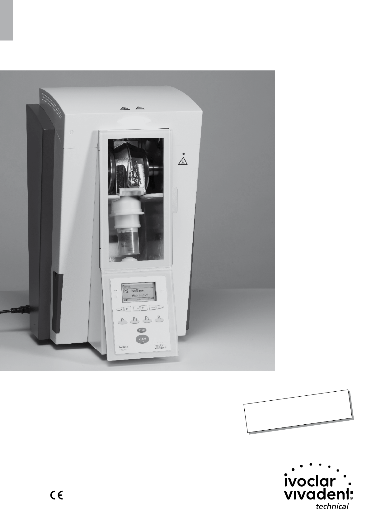
IvoBase® Injector
Operating Instructions
Valid as of
Software Version 2.0
Page 2

Table of Contents
List of parts 3
1. Introduction / Signs and Symbols 6
1.1 Preface
1.2 Introduction
1.3 Notes regarding the Operating Instructions
1.4 Note on the different voltage versions
2. Safety First 7
2.1 Indications
2.2 Health and safety instructions
3. Product Description 10
3.1 Components
3.2 Hazardous areas and safety equipment
3.3 Functional description
4. Installation and Initial Start-Up 11
4.1 Unpacking and checking the contents
4.2 Selecting the location
4.3 Removing the transport protection
4.4 Establishing the connections
4.5 Initial start-up
5. Operation and Configuration 14
5.1 Introduction to the operation
5.2 Explanation of key functions
5.3 Basic meaning of the screens
5.4 Settings and information
5.5 Explanation of the symbols on the display
5.6 Description of the beeper sounds
5.7 Operating status display
6. Practical Use 17
6.1 Switching on the injector
6.2 Loading
6.3 Starting the injection process
6.4 Further possibilities and special features of the injector
7. Maintenance, Cleaning and Diagnosis 19
7.1 Monitoring and maintenance
7.2 Emptying the waste water container
7.3 Replacing the heating
7.4 Replacing the temperature sensor
7.5 Cleaning
7.6 Heater test
7.7 Service Hint
7.8 Information about transport protection
8. What if...? 23
8.1 Error messages
8.2 Resin leaks from the flask
8.3 Resin leaks from the injection head
8.4 Technical malfunctions
8.5 Repair
9. Product Specifications 26
9.1 Delivery form
9.2 Technical data
9.3 Acceptable operating conditions
9.4 Acceptable transportation and storage conditions
10. Appendix 27
10.1 Program structure
2
Page 3

17
16
15
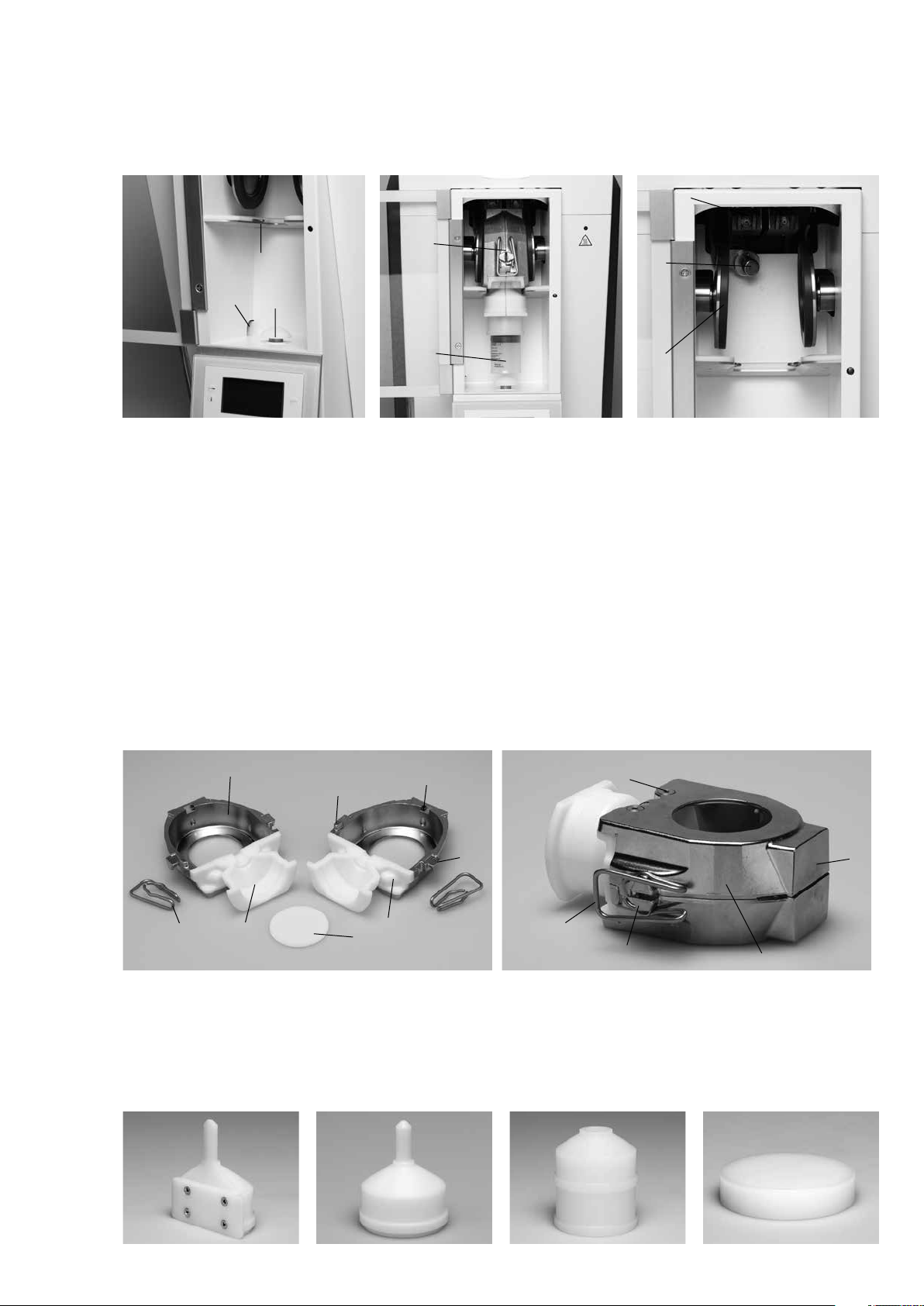
List of Parts
3
2
1
4
5
3
6
7
18
19
14
13
12
11
Injector:
1 Temperature sensor
2 Heater
3 Warnings
4 Operating Status Display (OSD)
5 Warning light
6 Clasps
7 Door handle
8 Polymerization chamber
9 Injection head
10 Operating panel
11 Rubber feet
12 Waste water container
13 Power cord
14 Housing
15 Capsule
16 Safety door
17 Flask
18 Knurled screw for hood
19 Air vents
20 On /Off switch
21 Power socket
22 Recessed grip
23 USB connection
24 Rating plate
25 Flask holder
26 Discharge opening
10
8
9
20
21
18
22
23
24
3
Page 4
25
2
17
1
26
Flask:
40 Isolating shoulder
41 Centering peg
42 Flask lid
43 Flask housing
44 Locking clasp attachment
9
15
45 Locking clasp
46 Recess for the aeration filter
47 Screws
48 Heating surface
49 Sensor surface
6
43
41
45
61 Access former half 62 Access former full 63 Centring insert 64 Deflasking aid
40
42
40
46
44
45
47
44
49
48
4
Page 5

Operating panel
71 Settings key
72 Information key
73 Right cursor key
74 Left cursor key
75 Program 2 key
76 Program 1 key
77 RMR key
78 – key
79 + key
80 ESC key
81 ENTER key
82 Next Program Number key
83 Program 3 key
84 STOP key
85 START key
86 START LED
100 Thermal glove
71
72
73
74
75
76
77
78
79
80
81
82
83
84
85
86
101 USB download cable
102 Temperature Checking Set
Please note that the list of parts applies
to the entire Operating Instructions.
References are made to the parts and /
or the numbering in later chapters.
5
Page 6
1. Introduction / Signs and Symbols
1.1 Preface
Dear Customer
Thank you for having purchased the IvoBase Injector. It is a modern
injection device for dental applications. The injector has been
designed according to the latest industry standards. Inappropriate
use may damage the equipment and be harmful to personnel.
Please observe the relevant safety instructions and read the Operating Instructions carefully.
Enjoy working with the IvoBase Injector.
1.2 Introduction
The signs and symbols in these Operating Instructions and on the
injector facilitate the finding of important information and have the
following meanings:
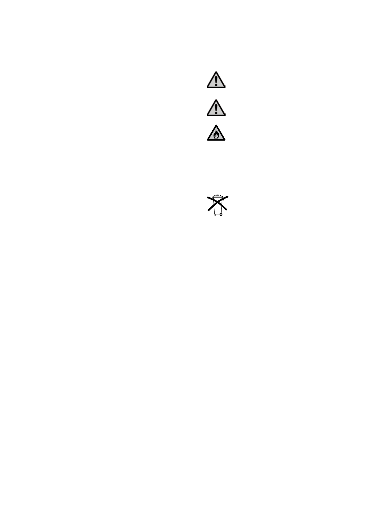
Risks and dangers
Important
information
Contraindication
1.3 Notes regarding the Operating Instructions
– Device concerned: IvoBase Injector
– Target group: Dental technologists
These Operating Instructions facilitate the correct, safe and economic use of the IvoBase Injector. Should you lose the Operating
Instructions, extra copies can be ordered at a nominal fee from your
local Ivoclar Vivadent Service Centre or downloaded in the Download Center at www.ivoclarvivadent.com/downloadcenter.
1.4 Note on the different voltage versions
The injector is suitable for the following voltage range:
100 – 120 V / 50 Hz – 60 Hz
200 – 240 V / 50 Hz – 60 Hz
No manual switch-over is necessary to use the individual voltage
versions. Please make sure that the voltage indicated on the rating
plate complies with the local power supply before setting the injector into operation.
Burn hazard
Risk of crushing
Fire hazard
The Operating Instructions must be read.
6
Page 7
2. Safety First
This chapter is especially important for individuals who
work with the IvoBase Injector or who have to carry out
maintenance or repair work. This chapter must be read
and the corresponding instructions followed!
2.1 I n d ication s
The IvoBase Injector is solely intended for the processing of special
resins for dental applications. It should be used for this purpose
only. Uses other than the ones stipulated, e.g. injection of other
materials, etc., are contraindicated. The manufacturer does not
assume any liability for damage resulting from misuse. The user is
solely responsible for any risk resulting from failure to observe these
Instructions.
Further instructions to assure proper use of the injector:
– The instructions, regulations and notes in these Operating
Instructions must be observed.
– The instructions, regulations and notes in the material's Instruc-
tions for Use must be observed.
– The injector must be operated under the indicated environmental
and operating conditions (see Chapter 9).
– The IvoBase Injector must be properly maintained.
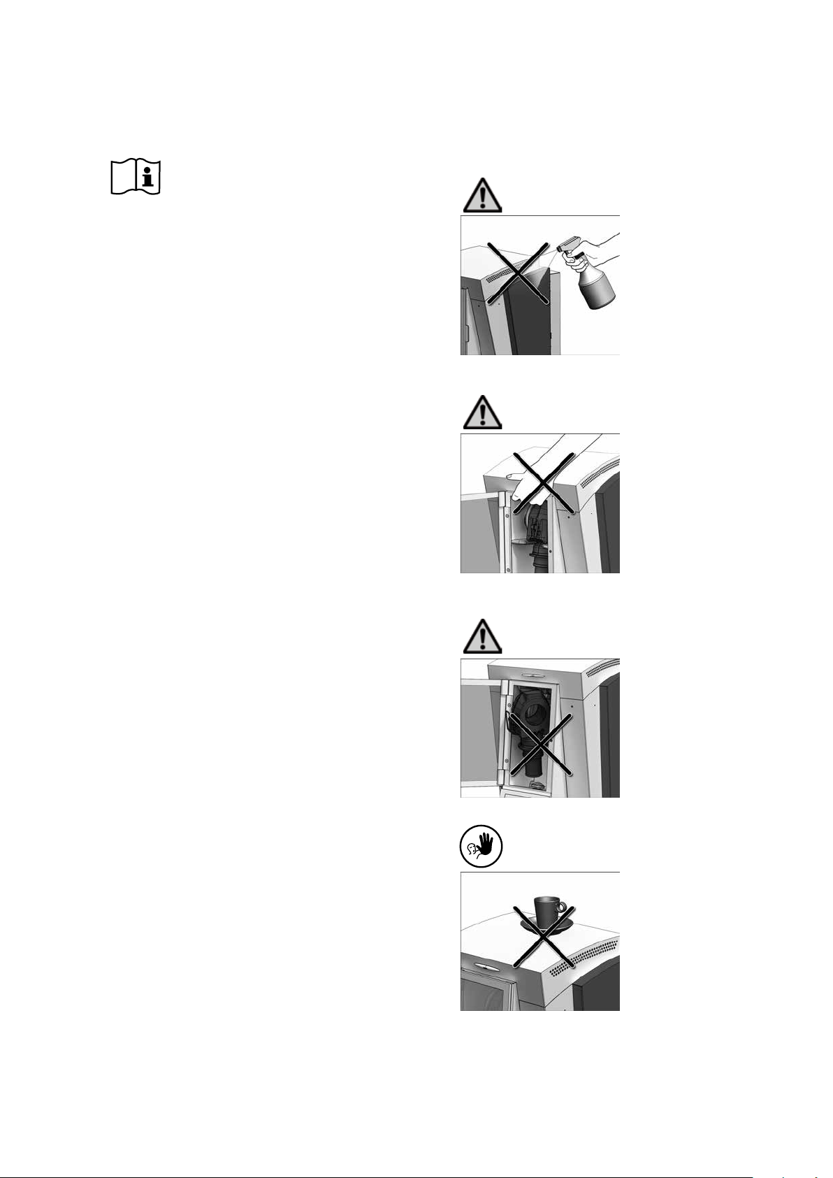
2.1.1
Risks and dangers
Make sure that no liquids or other
foreign substances enter the
injector during cleaning.
2.1. 2
Risks and dangers
The injector may only be carried
by supporting the bottom under
the operating field and by the
recessed grip at the rear of the
injector.
2.1.3
Risks and dangers
2.1. 4
Contraindication
Make sure that the flask is
correctly positioned.
The injection program must not
be started if the flask is
incorrectly positioned.
Foreign objects must not be
placed on the injector.
7
Page 8
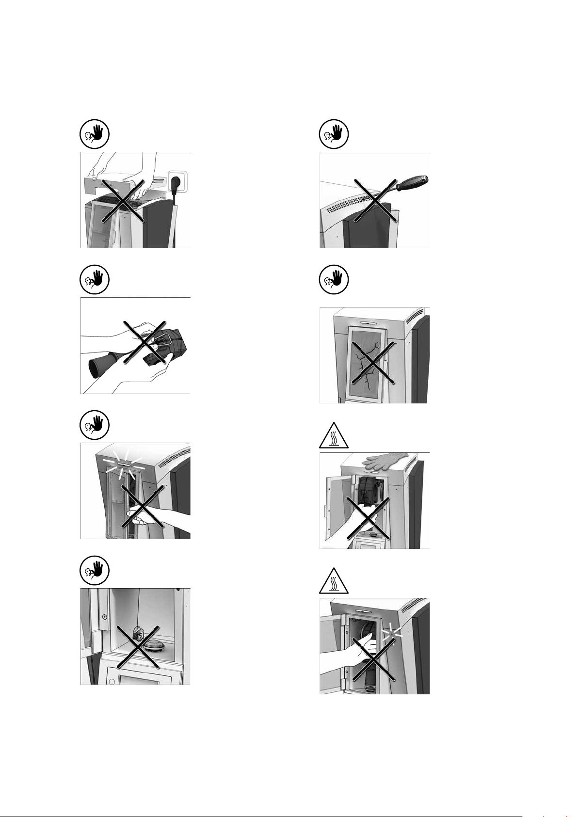
2.1. 5
Contraindication
2.1. 9
Contraindication
2.1. 6
Contraindication
2.1.7
Contraindication
The hood may only be removed
while the injector is switched off
and the power plug disconnected.
The locking clasp may only be
removed from the flask by rotating, rather than pushing it.
The safety door must not be
opened while a program is in
progress.
Foreign objects must not enter
the air vents.
2.1.10
Contraindication
The injector must not be operated
if it shows visible damage, for
example, at the heater, safety
door or clasps, etc.
2.1.11
Burn hazard
The flask must not be loaded or
removed from the injector without thermal glove.
2.1. 8
Contraindication
If the discharge outlet is clogged,
the injector must not be operated.
2.1.12
Burn hazard
Do not reach into the hot
injector!
Do not reach into the injector
while the red warning light is still
on. When switched off, the injector may still be hot even if the
warning light is not on.
8
Page 9
2.2 Health and safety instructions
This injector has been designed according to EN 61010-1 and has
been shipped from the manufacturer in excellent condition as far as
safety regulations are concerned. To maintain this condition and to
ensure risk-free operation, the user must observe the notes and
warnings contained in these Operating Instructions.
– It is important that the user becomes familiar with the warnings
and operating conditions to prevent injury to personnel or
damage to materials. The manufacturer is not responsible for
damage resulting from misuse or failure to observe the Operating
Instructions. Warranty claims cannot be accepted in such cases.
– Before switching on the injector, make sure that the voltage indi-
cated on the rating plate complies with your local power supply.
– The mains socket must be equipped with a residual current
operated device (FI).
– The power plug may only be inserted into sockets with protected
contacts.
– Place injector on a fire-proof table. Observe local regulations (e.g.
distance to combustible substances or objects, etc.).
– Always keep the air vents unobstructed.
– Do not touch any parts that become hot during operation of the
injector. Burn hazard!
– Clean injector only with a dry, soft cloth. Do not use any
solvents! Disconnect power before cleaning and allow the
injector to cool down!
– The injector must be cool before it is packed for transportation.
– Use original packaging for transportation purposes.
– Before calibration, maintenance, repair or change of parts, the
power must be disconnected and the injector has to be cool if it
has to be opened.
– If calibration, maintenance or repair has to be carried out with
the power connected and injector open, only qualified personnel
who are familiar with the risks and dangers may perform the procedures.
– After maintenance, the required safety tests (high voltage
resistance, protective conductor, etc.) must be carried out.
– Make sure that only fuses of the indicated type and rated current
are used.
– If it is assumed that safe operation is no longer possible, the
power must be disconnected to avoid accidental operation
– if the injector is visibly damaged.
– if the injector does not work.
– if the injector has been stored under unfavourable conditions
over an extended period of time.
– Use only original spare parts.
– Observe the correct temperature range to ensure faultless opera-
tion (see section 9.2 Technical data).
– If the injector has been stored at very low temperatures or high
atmospheric humidity, it must be dried or left to adjust to the
room temperature for approx. 4 hours prior to connecting power.
– The injector is tested for use at altitudes of up to 2000 m
(6562 ft) above sea level.
– The injector may only be used indoors.
Any disruption of the protective conductor either inside
or outside the injector or any loosening of the protective
conductor may lead to danger for the user in case of a
malfunction. Deliberate interruptions are not permissible.
Material developing harmful gases must not be
processed.
Monomer is used in the processing of denture base
material in the IvoBase Injector. This substance contains
methyl methacrylate (MMA), which is highly flammable.
Please handle this substance with care and avoid direct
skin contact. Please observe the detailed health and safety
instructions contained in the Instructions for Use of the
respective material.
Disposal:
The apparatus must not be disposed of in the normal
domestic waste. Please correctly dispose of old devices
according to the corresponding EU council directive.
Information regarding disposal can be found on the
respective national Ivoclar Vivadent website.
9
Page 10

3. Product Description
3.1 Components
The IvoBase Injector comprises the following components:
– Basic injector with polymerization chamber and operating panel
– Flask
– Waste water container
– Power cord
3.2 Hazardous areas and safety equipment
Description of the hazardous areas of the injector:
Hazardous area Type of risk
Polymerization chamber Burn hazard
Polymerization chamber Risk of crushing
Electrical components Risk of electrical shock
Description of the safety equipment of the injector:
Safety equipment Protective effect
Protective conductor Protection from electrical shock
Electrical fuses Protection from electrical shock
Housing and end caps Protection from electrical
shock, burning and crushing
Red warning light (5) Warns against hot components
in the polymerization chamber
3.3 Functional description
The IvoBase Injector has been developed for the IvoBase System and
allows an automated and controlled injection process. The injector
may be used for both self-curing and heat-curing polymers. The
integrated heater permits the flask to be heated up to 120 °C
(248 °F). With the controlled and automated injection, high-quality
products with outstanding physical properties can be fabricated.
The injection process taking place in the IvoBase Injector can be
basically divided into four stages (see image):
1. Dough stage: During this stage, the material changes to an
injectable consistency.
2. Injection phase: During this stage, the material is injected into the
flask by means of a forward movement of the injection head.
3. Polymerization stage: The controlled heat supply initiates the
polymerization with shrinkage compensation.
4. Cooling stage: During the cooling stage, the system normalizes
the temperature and the tension.
1. Dough
stage
2. Inje ction stage 3. Poly meriz ation stage
4. Cool ing
stage
(optional)
Temperature Injection force
10
Page 11

4. Installation and Initial Start-Up
3
2
3
4.1 Unpacking and checking the contents
The packaging provides the following advantages:
– Reusable packaging
– Closing mechanism with integrated transportation grips
– Ideal protection by Styrofoam inserts
– Easy handling during unpacking
– The packaging may be used in several ways (modules).
Remove the injector from the packaging and place it on a suitable
table. Please observe the instructions on the outer packaging.
Please keep in mind
that the IvoBase
Injector is very heavy.
It should always be
lifted and carried by
at least two people
(see image).
The IvoBase Injector is equipped with a special recessed grip at the
back and can conveniently be held at the operating panel at the
front.
4.2 Selecting the location
Place the injector on a flat table on the rubber feet. Make sure that
the injector is not placed in the immediate vicinity of heaters or
other sources of heat. Make sure that air may properly circulate
between the wall and the injector.
Also ensure that there is enough space between the injector and
the user, as the injector releases heat during the opening of the
sa fe ty d oor.
The injector should neither be placed nor operated in areas
where there is an explosion hazard.
4.3 Removing the transport protection
Once the injector has been set up, the transport protection
(adhesive tape) at the safety door and the waste water container
can be removed.
1
3
Check the delivery for completeness (see delivery form in Chapter 9)
and transportation damage. If parts are damaged or missing, contact your local Ivoclar Vivadent Service Centre.
Packing and shipping
The packaging may be discarded with the regular house-
hold refuse. However, we recommend keeping the original packaging for future service and transportation
purposes.
The packaging permits simple and safe shipping. Simply
use the corresponding plastic inserts and fold the side
flaps.
2
11
Page 12

4.4 Establishing the connections
Power connection
Please make sure that the voltage indicated on the rating plate
complies with the local power supply. Subsequently, connect the
power cord (13) with the power socket of the injector (21).
Connect the USB download cable.
If required, e.g. for software updates, connect the injector with a
laptop/PC using the USB cable (101) and the respective USB slot (23).
12
Page 13

4.5 Initial start-up
1. Connect the power cord (13) with the wall socket.
2. Put the On /Off switch (20) on position "I".
Immediately after switching on, the display shows the start screen
for a few seconds.
The injector now conducts an automatic self-test. During the test,
the performance of all injector components is automatically
checked. The display shows the following indications during the
self-test:
a)
b)
c) d)
a) Software version
b) Progress bar
c) Power supply voltage
d) Number of injections performed
If the program recognizes an error or a hint, the corresponding
information (e.g. "Hint 1700") appears on the display. If all
components are in order, the display will go to stand-by mode and
an acoustic signal will sound.
Make sure that the safety door is always closed during
the self-test.
Stand-by indicator
The stand-by indicator is shown after the self-test, and the last
program used before switching off will be loaded.
a)
b)
d)
c)
a) Status of the injector
b) Program number
c) Possible key strokes
d) Program name
13
Page 14

5. Operation and Configuration
5.1 Introduction to the operation
The IvoBase Injector is equipped with a graphic display with backlighting. The injector can be operated by means of the membranesealed keypad. The input and command keys can be used to
program and control the injector.
71
72
73
74
75
76
Key Function
77
78
79
80
81
82
83
84
85
86
Information
Serial number, software versions, etc.
ENTER, ESC keys
ENTER
Confirmation of the set numeric value.
ESC
– Ends an entry without accepting the
value.
– Return from the current to the previous
screen.
– Acknowledgement of error messages.
STOP
– A program in progress can be aborted
by pressing this key twice.
– The beeper can be confirmed by
pressing the STOP key.
START (Start LED)
Starts the selected program. The green LED
indicates that a program is running.
RMR (Residual Monomer Reduction)
With this function, the residual monomer
content can be reduced to below 1%
(acc. to ISO 20795-1).
5.2 Description of the key functions
Key Function
Program 1 key
Pressing results in the direct change to
Program 1.
Program 2 key
Pressing results in the direct change to
Program 2.
Program 3 key
Pressing results in the direct change to
Program 3.
Next Program Number key
Pressing results in the direct change to the
next higher program number.
Cursor keys left, right
These keys are used to move the cursor.
Minus/Plus keys
These keys are used to change the numeric
value.
Settings
Settings, programming, special programs,
etc.
5.3 Basic meaning of the screens
– Stand-by
Injector and /or
program status
Recommendation area
– Program progress screen
Program status
Currently selected
program
Program or
material name
Progress bar
Status area
The most important information is displayed in the
main screen.
The most likely nex t
action is indicated here.
Remaining time indicator
Graphic
status information
14
Page 15

5.4 Settings and information
By pressing the "Settings" key (71) you can access the
settings screen (the latest selected settings will be indicated).
The cursor keys (73, 74) can be used to toggle between possible
settings. This screen can be exited with the ESC key (80) or any of
the program keys (75, 76, 83).
5.4.1 Settings
Settings marked with "*" are protected by Ivoclar
Vivadent with a code. The code is communicated if
changes become necessary.
Settings
Contrast
Temperature unit
Language
selection
Volume
Melody
Programming *
Indication on
display
Short description
The contrast can be
changed by means of
– or +.
The – and + keys can
be used to toggle
between °C and °F.
Enables the language
selection.
The volume can be
adjusted by means of
– or +.
The desired tune can
be set using – or +.
Allows the parameters
of the currently selected program to be set.
Settings
General write
protection
Keypad test
Heater test
Transport
protection
Service interval
Load factory
settings
5.4.2 Information
By pressing the "Information" key (72) you can access the information screen (the latest selected information will be indicated). The
cursor keys (73, 74) can be used to toggle between the possible
information. This screen can be exited with the ESC key (80) or any
of the program keys (75, 76, 83).
Information
Serial number
Indication on
display
Indication on
display
Short description
Permits activation or
deactivation of the
general write protection (using – or +)
once the user password has been
entered. The general
write protection
applies to all the
programs.
Permits checking the
keypad.
Permits the examination
of the heater system.
See Chapter 7.6
Heater test for details.
Activates the transport
protection.
See Chapter 7.8
Select the interval for
the next reminder. The
interval is set in
months.
Resets all the values
and parameters to the
factory settings.
Short description
Serial number of the
device
Renaming *
Time
Date
Permits renaming of
the currently selected
program.
Permits renaming the
material.
The time can be set
using the – or + keys.
The date can be set
using the – or + keys.
Software version
Program cycles
Operating hours
15
Currently installed
software version
Sum of all the executed program cycles
(injections)
Page 16
Settings
Date of the latest
calibration
Supply voltage
List of errors
Indication on
display
Short description
Shows the current
supply voltage.
5.5 Explanation of the symbols on the display
Symbol name Explanation Symbol
Shows that the door is open.
Door open
Start possible
Program write
protection
General write
protection
Page selection
The door must be closed in
order to start a program.
Shows that the injector is
ready to use. The door is
closed and a program can be
started.
A closed lock indicates that
the program write protection
is active. With an open lock,
this protection is inactive
(adjustable with the – or +
key).
If this symbol is displayed, the
general write protection is
active. This protection applies
to all injector programs.
Program parameters are
available on two pages. By
selecting the appropriate
symbol with the cursor key
and by pressing ENTER, the
program changes to the
respective page.
5.6 Description of the beeper sounds
Basically, the beeper tune and volume set by the user are used for
all acoustic signals. The acoustic signal can be stopped by pressing
STOP.
1. After the self-test has been completed
The set beeper tune briefly sounds to inform the user that the
automatic self-test has been successfully completed.
2. In the case of error messages
Error messages are indicated with the error beeper tune (endless
beeping). The beeper can be confirmed by pressing the STOP key,
while the error message still remains visible. If the error message
is confirmed by pressing the ESC key, the beeper is also ended.
3. At the end of an injection program
The set beeper tune briefly sounds to inform the user that the
current program has been completed.
4. Upon opening of the safety door during an injection program in
progress
If the safety door is opened while an injection program is
running, the user is warned by the error tune (endless beeping).
The acoustic signal can be stopped by closing the safety door.
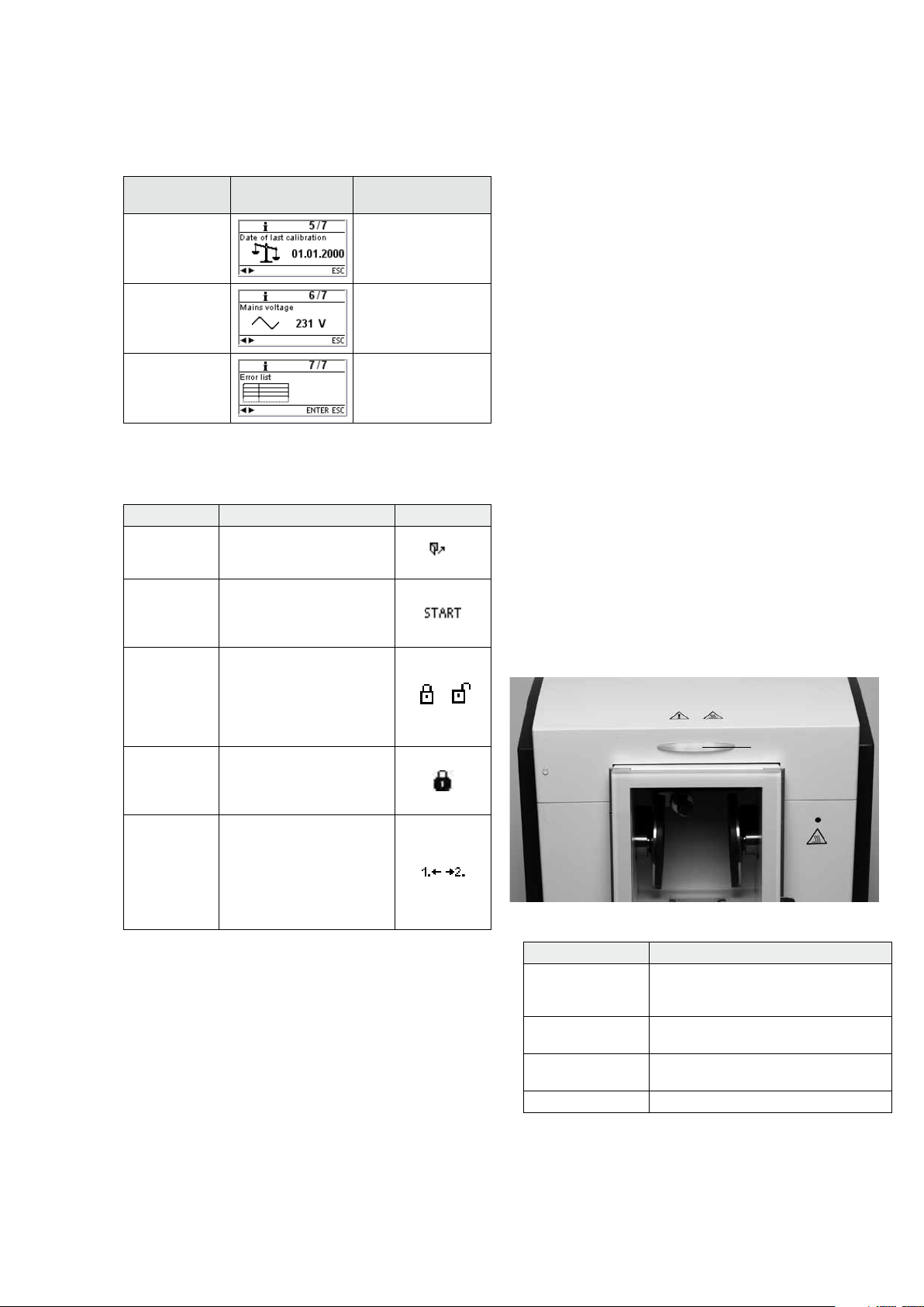
5.7 Operating status display
The integrated optical operating status display (OSD) indicates the
different operating statuses of the injector.
13
The following activities are indicated:
Colour Activities
green The injector is ready for operation (with
the door closed and the self-test
completed).
white The injector is in the preparation stage
(with the door open).
red The injection process is active; injector is
busy.
yellow (flashing) Information, note or error message.
16
Page 17

6. Practical Use
6.1 Switching on the injector
Put the On/Off switch (20) on position "I". The injector now conducts an automatic self-test. Make sure that the injector is not
manipulated during that time.
6.1.1 Stand-by screen
If the self-test has been successfully completed, the stand-by
screen is displayed. Now the desired program can be selected with
the program or cursor keys.
Once the flask has been placed in
the injector and the safety door
has been closed, the START
symbol appears in the recommendation section. The selected program is started by pressing START.
6.1.2 Program progress screen
After the program has been started, the program progress screen is
displayed.
Program status
Currently selected
program
Program or
material name
Progress bar
Remaining time indicator
Graphic
status information
6.2 Loading
To load the IvoBase Injector, proceed as follows:
Please read the following processing notes
carefully.
– Make absolutely sure that both flask halves have cooled to room
temperature before injection. A temperature of >30 °C (>86 °F)
jeopardizes controlled polymerization and might lead to
inaccuracies of fit.
– When working with self-curing materials, make sure that as little
time as possible lies between mixing the material and injection.
A lit warning light (5) indicates that the injector tempera-
ture is high during loading or removal and, therefore,
there is a burn hazard (>45 °C/>113 °F).
Always use the thermal glove supplied when
removing the flask from the injector!
6.3 Starting the injection process
For practical use, please observe the Instructions for Use
of the respective material!
Step 1:
Select the desired program (P1 to P20) using the program or cursor
keys.
Step 2:
Open the safety door and insert the flask into the injector. The flask
perceptibly snapping into place indicates the correct position.
Step 1:
Open the safety door (16).
Step 2:
Slide the flask into the holder intended for this purpose as shown in
the picture.
Make sure that the flask is securely placed and that it has
been inserted until it stops. The flask perceptibly
snapping into place indicates the correct position.
Step 3:
Close the door. If the OSD lights up green, the injector is ready for
the process.
Step 3:
Close the safety door. The injector cannot be started if the door is
open. Press Start to start the program.
The course of the program can be observed on the program
progress indicator.
6.4 Further possibilities and special features of the
injector
6.4.1 General write protection
If the programs are write protected as a whole, a closed, solid lock
is displayed in the parameter list. The setting "Renaming" cannot be
selected if the write protection is active. A hint in the form of closed
lock is shown next to the keyboard symbol.
6.4.2 Stopping the running program
Pressing STOP once results in the
program abort screen being displayed.
You can now abort the program
by pressing the STOP key again, or
you can press ESC and the program abort screen disappears and the program is resumed.
17
Page 18

If the safety door is opened while an injection pro-
gram is running, the program is stopped for safety
reasons. While the program is interrupted, the
green LED in the START key flashes. The process is
automatically resumed once the door has been
closed.
6.4.3 RMR function (Residual Monomer Reduction)
Pressing the RMR key (77) activates the RMR function. This means
that the residual monomer content of the processed material can be
reduced to below 1%.
6.4.6 Software update
The user will be able to conduct a software update via PC and USB
download cable. For that purpose, the software download mode is
activated by pressing two special keys simultaneously while the
power supply is switched on. For further details, please refer to the
Software Update Instructions in the Download Center
(ww w.ivoclarvivadent.com /downloadcenter).
18
Page 19
7. Maintenance, Cleaning, Diagnosis
This chapter describes the user maintenance and cleaning procedures for the IvoBase Injector. Only those tasks are listed that may
be performed by dental professionals. All other tasks must be performed by qualified service personnel at a certified Ivoclar Vivadent
Service Centre.
The time for these maintenance procedures depends on the frequency of use and the working habits of the users. For that reason,
the recommended times are only approximations.
This injector has been developed for typical use in dental
laboratories. If the product is used for continuous operation, premature ageing of the expendable parts has to
be expected.
Expendable parts are, for instance:
– Heater
– Clasps
Expendable parts are not covered by the warranty.
Please also observe the shorter service and maintenance intervals.
7.1. Monitoring and maintenance
What: When:
Check all plug-in connections for correct fit. weekly
Check the water level in the waste water container and empty it, if necessary (see 7.2 for
details).
Check if the heater is dirty or damaged (see 7.3
for details).
Check if the temperature sensor in the polymerization chamber is dirty or damaged (see
7.4 for details).
Check if the safety door is dirty or damaged. daily
Check the keypad for visible damage. If the keypad is damaged, it has to be replaced by a
certified Ivoclar Service Centre.
daily
weekly
weekly
weekly
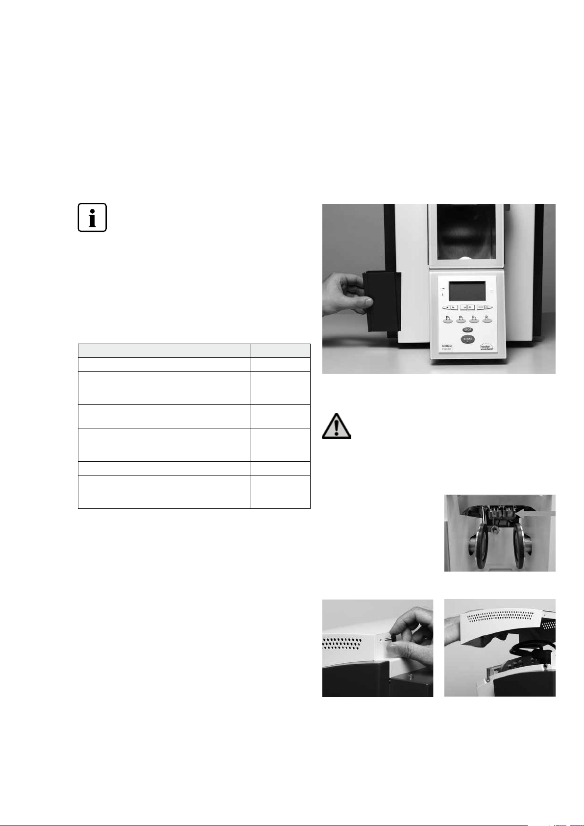
7.2 Emptying the waste water container
During the polymerization process, condensation develops within
the injector, which is discharged via a drain outlet. Check the water
level at regular intervals and empty the waste water container, if
necessary.
The waste water container can be removed from and replaced in
the injector as shown in the picture.
7.3 Replacing the heater
Before replacing the heater, disconnect the injector from
the power supply.
The heater system of the IvoBase Injector has been developed in
such a way that users may replace it by themselves, if required
(cleaning, defect).
Dismounting the heater:
To dismount the heater, please
proceed as follows:
Step 1:
Remove the two knurled screws at the rear and remove the hood.
19
Page 20
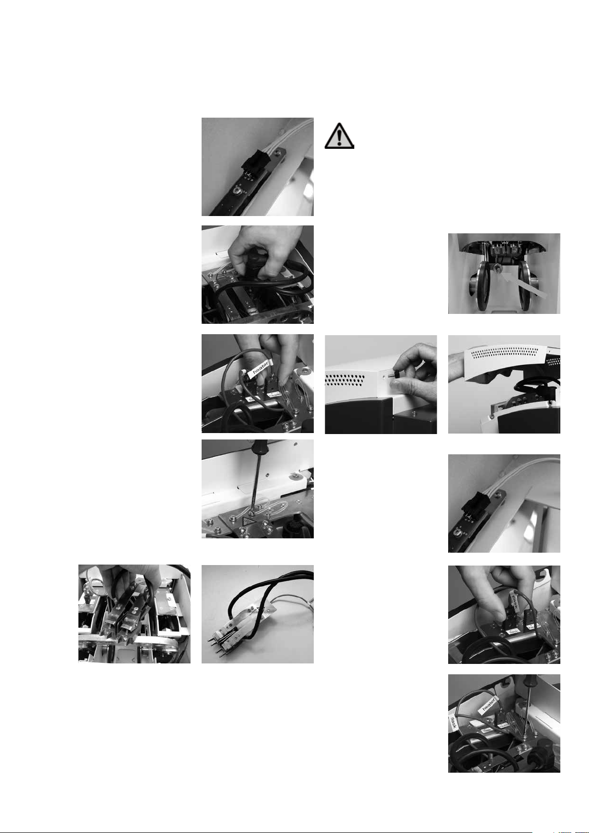
Step 2:
Unplug the cable for the OSD.
Step 3:
Unplug the heater plug.
Step 4:
Unplug the plug with the label
"heater".
7.4 Replacing the temperature sensor
Before replacing the temperature sensor, disconnect the
injector from the power supply.
The temperature sensor of the IvoBase Injector has been developed
in such a way that users may replace it by themselves, if required
(cleaning, defect).
Check weekly if the temperature sensor is damaged and/or bent.
Also, check it for correct fit or other damage.
Dismounting the temperature sensor:
To dismount the temperature
sensor, please proceed as follows:
Step 1:
Remove the two knurled screws at the rear and remove the hood.
Step 5:
Remove the screws of the
he at er.
Step 6:
Remove the heater. Dismounted heater.
Mounting the heater:
Place the heater back in its original position (align the heater in the
centre with the help of an inserted flask) and secure it in place with
the screws. (The heater is mounted in the same way as it is dismounted. Follow the Steps 6 to 1.)
Step 2:
Unplug the cable for the OSD.
Step 3:
Unplug the plug with the label
"fla s k ".
Step 4:
Remove the screws of the
sensor.
20
Page 21
Step 5:
Remove the sensor. Dismounted sensor:
Mounting the temperature sensor:
Mounting the temperature sensor is carried out in the same way as
dismounting. Simply reverse the order of the above steps (Step 5 to
Step 1).
7.5 Cleaning
The injector may only be cleaned when it is cool, since
there is a burn hazard. Do not use any cleaning
solutions. Disconnect the power to the injector before
cleaning.
The following parts have to be cleaned from time to time:
What When Cleaning material
Injector housing and
membrane-sealed keypad
Safety door if required soft cloth
if required soft, dry cloth
Step 2:
Clean the IvoBase polymerization chamber, heater and temperature
sensor while they are cold. Please make sure that the contact surfaces of the heater and the temperature sensor are clean.
Step 3:
Close the flask with the locking
clamps and attach a measuring
point to the spot on the left flask
half shown in the picture (see
picture). It is important that the
exact position is observed. Only in
this way can correct measuring
values be achieved.
Step 4 :
Load the IvoBase Injector with the test flask and close the safety
do or.
Step 5:
Select the heater test program with the „Settings“ key. Confirm
your selection with the Enter key.
Step 6:
Start the test program using the
Start key. The flask is heated to
100 °C / 212 °F for approximately
10 minutes. The remaining time is
indicated in the display. The
Operating Status Display is not
illuminated during the heating
phase.
Important: The door must not be
opened during the test. If this is
not observed, the test program is
immediately aborted.
Polymerization
chamber
Flask and flask
accessories *
* The flask housing may show a dark discolouration, for instance,
when plaster material is left in the flask for a longer period. This
oxide layer can be removed by means of pumice flour. This dark
layer does not influence the usability of the flask in any way.
if required soft cloth
after every use water
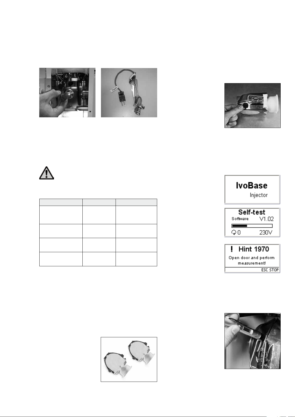
7.6 Heater test
The heater test is used to check the observance of the temperature
in the IvoBase Injector independently and at regular intervals.
For that purpose, proceed as follows:
Step 1:
Fabricate a test flask that is
exclusively filled with stone
(without model – see Fig. 1). If the
stone in the flask set a longer
while ago and is dry, the flask has
to be soaked in water before the
test.
Step 7:
After the program is completed,
the message „Hint 1970“ appears
in the display, with the prompt to
determine the temperature now.
The acoustic signal can be
switched off with the ESC key.
Step 8 :
Open the safety door and conduct the measurement. In order to
obtain the most reliable result, conduct several measurements in
close succession. The available time window for that purpose is
60 seconds. This time must not be exceeded, since the flask would
cool down too much and the measurement would be skewed.
Important: The sensor of the
IR thermometer must be held as
closely as possible to the
measuring point (see picture).
However, a small air gap should
be present. Measurements directly
on the metal surface without
measuring point are not
admissible, since these
measurement can be skewed by
reflections.
21
Page 22

Step 9:
Analyze the measurement. The measuring results must be in the
following temperature range:
– Min.: 90 °C / 194 °F
– Max.: 110 °C / 230 °F
If the measured value is not within this range, please contact your
Ivoclar Vivadent Service Centre.
Step 10 :
Press the Stop key to end the test. After that, remove the
flask from the injector and remove the measuring point.
7.7 Service Hint
When the Service Hint is displayed for the first time ( Hint 1700),
3 years have passed or 10,000 cycles have been carried out. Therefore, Ivoclar Vivadent recommends having a maintenance procedure
performed on the injector. The interval until the next appearance of
the Service Hint can be changed in the Settings (see Section 5.4.1).
7.8 Information about transport protection
In order to transport the Ivobase Injector, the clamps must be
brought into a transport position. This function can be activated in
the Settings (see Chapter 5.4 Settings and information).
22
Page 23
This chapter will help you to recognize malfunctions and take appropriate measures.
8.1 Error messages
During operation, the injector continuously monitors all the functions. If an error is
detected, the respective error message is displayed.
8. What if....?
Error / Hint
No.
170 0 Service reminder Three years have passed since the last technical inspection of the injector. Therefore,
190 0 Door is open. Once a program has been started, the door must remain closed. Close the door. The program will
1901
**
1913
**
1914
**
1917 Power failure A program in progress will automatically resume, irrespective of the duration of the power failure.
1920
**, ***
1921
**, ***
1928 Checking the start temperature The flask is too hot to start a program. Press START to start the program any way.
1930
**, ***
1935
**,***
1936 Low amount of material in capsule The injection motor has reached the maximum travelling distance. The amount of material in the
1941
**
196 0
**
1970 Open door and conduct measure-
1971
**
1972 Heater test completed At the end of the heater test, the temperature of the flask must be determined within one minute.
198 0 Switch off device At the end of the transport protection program, the IvoBase Injector can be transported safely. The
** A program in progress is aborted. *** Error cannot be acknowledged; programs cannot be started.
Error Text Error Message
Ivoclar Vivadent recommends having a maintenance procedure performed on the injector. For further
information, please refer to the Equipment Ser vice Passport or the Operating Instructions. The inter val
until the nex t appearance of the Service Hint can be changed in the Settings.
automatically resume.
Hood is missing. The injector hood may only be removed for maintenance purposes. The
Insert the flask. Insert a flask into the injector and start the program again.
Insert the capsule. Insert a flask including a material capsule into the injector and start the program again.
Technical malfunction heater/sensor No temperature increase in the flask was noted during the polymerization phase.
Technical malfunction heater/sensor No temperature increase of the heater was noted during the polymerization phase.
Technical malfunction heater/sensor The function of the heater is checked during the self-test. No temperature increase is noticeable.
Technical defec t; service The press motor has exceeded the permitted travelling distance.
Press force too low! The press force which squeezes the flask halves together is too low (sudden pressure drop).
The door is open during the self-test. The door must be closed during the self-test. Close the door and switch the injector off and on
ment
Heater test aborted If the door is opened during the heater test or the cover removed from the injector, the test pro -
injector must be turned off beforehand. The injector cannot be started without the hood in place.
capsule is low. Reasons for this could be: There is not sufficient material in the capsule for the dental
lab work. Material leaks from a flask.
again.
At the end of the heater test, open the door and use the supplied IR thermometer to determine the
temperature of the flask.
gram is aborted. Manual abortion is also possible by pressing Stop t wice.
After a longer waiting time, the flask has cooled down too much.
device can now be switched off.
If one of the following error codes is displayed, please contact the Ivoclar Vivadent After Sales Service directly.
25, 29,
54, 56,
103, 107,
700, 701, 705, 706 707,
1010, 1011, 1012, 1013, 1014, 1015, 1016, 1028
1202, 1203, 1204, 120 6 , 12 07
140 0, 1401, 1402
150 0
1910, 1911, 1912, 1931, 1935, 1950, 1951, 1952, 19 53
23
Page 24
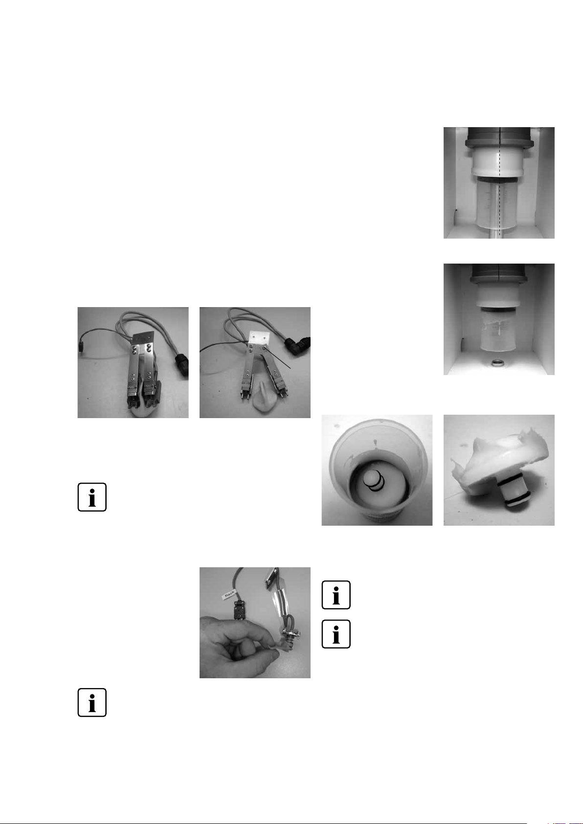
8.2 Resin leaks from the flask
Under certain circumstances – e.g. if the filter component was forgotten to be placed in the flask (see Instructions for Use of the
corresponding materials) – resin may leak from the flask during
injection. This results in contamination of the heating shoes or the
temperature sensor. Please proceed as follows in such cases:
8.2.1 Cleaning the heater
Step 1:
Dismounting the heater: Proceed as described in section 7.3 of
these Operating Instructions.
Step 2:
The heater consists of two heating elements. Loosen both screws
on one of the two heating elements. One screw (a) must be completely loosened and removed. Subsequently, this heating element
can simply be swivelled away from the the remaining element.
Polymerized resin material can then be easily removed from the
heater (see image).
a)
Step 3:
After having cleaned the heater, mount it in the injector again.
Swivel the heating element back to its original position and tighten
the screw that was previously removed (see image). To insert the
heater, proceed as described in Section 7.3.
8.3 Resin leaks from the injection head
In case of a malfunction, resin may
leak from the material capsule
during injection (e.g. if the plunger is tilted in the material capsule
– see image). If leaked and
polymerized material is deposited
in the material capsule, the injection head may get stuck in the
capsule, since it is not fixedly connected with the plunger.
If this is the case, proceed as
follows:
Step 1:
Wait until the program has
ended and the plunger has
moved all the way down.
Step 2:
Remove the injection head of the material capsule and completely
remove the material.
Wait until the material has completely set /
polymerized before removing it.
8.2.2 Cleaning the temperature sensor
Step 1:
Dismounting the temperature sensor. Proceed as described in section 7.4 of these Operating Instructions.
Step 2:
Carefully remove the material
from the temperature sensor.
Step 3:
Remount the temperature sensor
in the injector (see 7.4)
Wait until the material is completely set/
polymerized before removing it.
Step 3:
Replace the injection head in the plunger. The head is pushed in –
there is no screw connection to the plunger.
Wait until the material has completely set /
polymerized before removing it.
To insert the injection head in the plunger, dampen
the rubber rings of the injection head.
24
Page 25

8.4 Technical malfunctions
These malfunctions may occur without an error message being displayed:
Error Double-check Measure
Display incomplete Contact Ivoclar Vivadent After Sales Service.
Text on the display is difficult to read. Is the contrast set correctly? Adjust the contrast.
Display is not illuminated. Has the injector been correctly connected
and switched on according to the Operating
Instructions?
Buzzer does not sound. Is the beeper switched off (Volume = 0)? Set the volume from 1–5.
Correctly connect and switch on the injector.
8.5 Repair
Repairs may only be carried out by a certified Ivoclar
Vivadent Service Centre. Please refer to the addresses on
the last page of these Operating Instructions.
If repairs during the warranty period are not carried out by a
certified a Ivoclar Service Centre, the warranty will expire
immediately. Please also refer to the corresponding warranty
regulations.
25
Page 26

9. Product Specifications
9.1 Delivery form
– IvoBase Injector
– Power cord
– USB download cable
– 2 Sets of flasks
– Thermal glove
– Temperature Checking Set
– var. accessories
– Warranty Card, Operating Instructions, Service Passport
9.2 Technical data
Nominal voltage 100 – 120 V / 200 – 240 V
Nominal frequency 50 Hz – 60 Hz
Acceptable voltage fluctuations +/– 10%
Nominal output 450 W
Protection category I
Overvoltage category II
Contamination level 2
Dimensions Depth: 400 mm
Width: 340 mm
Height: 560 mm
Max. temperature 300 °C (572 °F)
Weight 35.6 kg
9.3 Acceptable operating conditions
Acceptable ambient temperature:
+5 °C to +40 °C / +41°F to +104 °F
Acceptable humidity range:
Relative humidity 80% for temperatures up to 31 °C / 87.8 °F
gradually decreasing to 50% relative humidity at 40 °C / 104 °F
condensation excluded.
Acceptable ambient pressure:
The injector is tested for use at altitudes of up to 2000 m ( 6562 ft)
above sea level.
9.4 Acceptable transportation and storage conditions
Acceptable temperature range: –20 °C to +65 °C / –4 °F to +149 °F
Acceptable humidity range: Max. 80% relative humidity
Acceptable ambient pressure: 500 mbar to 1060 mbar
Use only the original packaging together with the corresponding
foam material for shipping purposes.
Safety notes
The IvoBase Injector complies with the following guidelines:
– IEC 61010-1:2001
– EN 61010 -1:2001
– UL 61010 -1:200 4
– CAN/CSA-C22.2 No. 61010 -1:2004
– IEC 61010-2-010 :2003
– EN 61010 -2- 010:20 03
– CAN/CSA-C22.2 No. 61010-2-010:20 04
Radio protection / electromagnetic compatibility EMC tested
26
Page 27

10.1 Program structure
10. Appendix
Program
No.
1 IvoBase Hybrid
2 IvoBase High Impact
3 SR Ivocap High Impact
4 SR Ivocap Clear
5 SR Ivocap Elastomer Program for the polymerization of the SR Ivocap Elastomer material 65 min
6–20 Ivoclar Vivadent – Spare Space for future Ivoclar Vivadent injection programs.
Name Description Duration
Program for the polymerization of the IvoBase Hybrid material,
residual monomer <= 1.5%
Program for the polymerization of the IvoBase Hybrid material with additional
RMR, residual monomer <= 1.0%
Program for the polymerization of the IvoBase High Impact material,
residual monomer <= 1.5%
Program for the polymerization of the IvoBase High Impact material with additional RMR, residual monomer <= 1.0%
Program for the polymerization of the SR Ivocap High Impact material, residual
monomer <= 1.5%
Program for the polymerization of the SR Ivocap High Impact material with
additional RMR, residual monomer <= 1.0%
Program for the polymerization of the SR Ivocap Clear material, residual
monomer <= 1.5%
Program for the polymerization of the SR Ivocap Clear material with additional
RMR, residual monomer <= 1.0%
35 min
45 min
50 min
60 min
55 min
65 min
55 min
65 min
27
Page 28

Ivoclar Vivadent – worldwide
Ivoclar Vivadent AG
Bendererstrasse 2
9494 Schaan
Liechtenstein
Tel. +423 235 35 35
Fax +423 235 33 60
www.ivoclarvivadent.com
Ivoclar Vivadent Pty. Ltd.
1 – 5 Overseas Drive
P.O. Box 367
Noble Park, Vic. 3174
Australia
Tel. +61 3 9795 9599
Fax +61 3 9795 9645
www.ivoclarvivadent.com.au
Ivoclar Vivadent Ltda.
Alameda Caiapós, 723
Centro Empresarial Tamboré
CEP 06460-110 Barueri – SP
Brazil
Tel. +55 11 2424 7400
Fax +55 11 3466 0840
www.ivoclarvivadent.com.br
Ivoclar Vivadent Inc.
1-6600 Dixie Road
Mississauga, Ontario
L5T 2Y2
Canada
Tel. +1 905 670 8499
Fax +1 905 670 3102
www.ivoclarvivadent.us
Ivoclar Vivadent Shanghai
Trading Co., Ltd.
2/F Building 1, 881 Wuding Road,
Jing An District
200040 Shanghai
China
Tel. +86 21 6032 1657
Fax +86 21 6176 0968
www.ivoclarvivadent.com
Ivoclar Vivadent Marketing Ltd.
Calle 134 No. 7-B-83, Of. 520
Bogotá
Colombia
Tel. +57 1 627 3399
Fax +57 1 633 1663
www.ivoclarvivadent.co
Ivoclar Vivadent SAS
B.P. 118
F-74410 Saint-Jorioz
France
Tel. +33 4 50 88 64 00
Fax +33 4 50 68 91 52
www.ivoclarvivadent.fr
Ivoclar Vivadent GmbH
Dr. Adolf-Schneider-Str. 2
D-73479 Ellwangen, Jagst
Germany
Tel. +49 7961 889 0
Fax +49 7961 6326
www.ivoclarvivadent.de
Wieland Dental + Technik
GmbH & Co. KG
Schwenninger Strasse 13
D-75179 Pforzheim
Germany
Tel. +49 7231 3705 0
Fax +49 7231 3579 59
www.wieland-dental.com
Ivoclar Vivadent Marketing (India)
Pvt. Ltd.
503/504 Raheja Plaza
15 B Shah Industrial Estate
Veera Desai Road, Andheri (West)
Mumbai, 400 053
India
Tel. +91 22 2673 0302
Fax +91 22 2673 0301
www.ivoclarvivadent.in
Ivoclar Vivadent s.r.l.
Via Isonzo 67/69
40033 Casalecchio di Reno (BO)
Italy
Tel. +39 051 6113555
Fax +39 051 6113565
www.ivoclarvivadent.it
Ivoclar Vivadent K.K.
1-28-24-4F Hongo
Bunkyo-ku
Tokyo 113-0033
Japan
Tel. +81 3 6903 3535
Fax +81 3 5844 3657
www.ivoclarvivadent.jp
Ivoclar Vivadent Ltd.
12F W-Tower, 1303-37
Seocho-dong, Seocho-gu,
Seoul 137-855
Republic of Korea
Tel. +82 2 536 0714
Fax +82 2 596 0155
www.ivoclarvivadent.co.kr
Ivoclar Vivadent S.A. de C.V.
Av. Insurgentes Sur No. 863,
Piso 14, Col. Napoles
03810 México, D.F.
México
Tel. +52 55 5062 1000
Fax +52 55 5062 1029
www.ivoclarvivadent.com.mx
Ivoclar Vivadent BV
De Fruittuinen 32
2132 NZ Hoofddorp
Netherlands
Tel. +31 23 529 3791
Fax +31 23 555 4504
www.ivoclarvivadent.com
Ivoclar Vivadent Ltd.
12 Omega St, Rosedale
PO Box 303011 North Harbour
Auckland 0751
New Zealand
Tel. +64 9 914 9999
Fax +64 9 914 9990
www.ivoclarvivadent.co.nz
Ivoclar Vivadent Polska Sp. z o.o.
Al. Jana Pawla II 78
00-175 Warszawa
Poland
Tel. +48 22 635 5496
Fax +48 22 635 5469
www.ivoclarvivadent.pl
Ivoclar Vivadent Marketing Ltd.
Prospekt Andropova 18 korp. 6/
office 10-06
115432 Moscow
Russia
Tel. +7 499 418 0300
Fax +7 499 418 0310
www.ivoclarvivadent.ru
Ivoclar Vivadent Marketing Ltd.
Qlaya Main St.
Siricon Building No.14, 2
Office No. 204
nd
Floor
P.O. Box 300146
Riyadh 11372
Saudi Arabia
Tel. +966 11 293 8345
Fax +966 11 293 8344
www.ivoclarvivadent.com
Ivoclar Vivadent S.L.U.
C/ Ribera del Loira nº 46, 5ª planta
28042 Madrid
Spain
Tel. + 34 913 757 820
Fax + 34 913 757 838
www.ivoclarvivadent.es
Ivoclar Vivadent AB
Dalvägen 14
S-169 56 Solna
Sweden
Tel. +46 8 514 939 30
Fax +46 8 514 939 40
www.ivoclarvivadent.se
Ivoclar Vivadent Liaison Office
: Tesvikiye Mahallesi
Sakayik Sokak
Nisantas’ Plaza No:38/2
Kat:5 Daire:24
34021 Sisli – Istanbul
Turkey
Tel. +90 212 343 0802
Fax +90 212 343 0842
www.ivoclarvivadent.com
Ivoclar Vivadent Limited
Ground Floor Compass Building
Feldspar Close
Warrens Business Park
Enderby
Leicester LE19 4SE
United Kingdom
Tel. +44 116 284 7880
Fax +44 116 284 7881
www.ivoclarvivadent.co.uk
Ivoclar Vivadent, Inc.
175 Pineview Drive
Amherst, N.Y. 14228
USA
Tel. +1 800 533 6825
Fax +1 716 691 2285
www.ivoclarvivadent.us
Version : 3
Date of issue: 2014-01
Valid as of Software 2.0
The appara tus has been dev eloped sol ely for use in den tistry. Star t-up and
operation should be carried out strictly according to the Operating Instructions.
Liabilit y cannot be acce pted for damage s resulting fro m misuse or failure t o
observ e the Instruc tions. The u ser is solel y responsibl e for testing the a pparatus
for its suit ability for any p urpose not e xplicitly s tated in the Ins truction s.
Descript ions and data co nstitute no war ranty of attr ibutes and are n ot binding.
Printed in Aus tria
© Ivoclar Vivadent AG, Schaan/ Liechtenstein
6420 03/en /2014-01-29
 Loading...