

Page 1

InLine® One
IPS
One-layer metal-ceramic
InLine
IPS
InLine
IPS
Conventional metal-ceramic
Instructions for Use
®
®
InLine® PoM
IPS
Press-on-Metal ceramic
Page 2
InLine® One
IPS
One-layer metal-ceramic
Optimize your working procedures and simultaneously increase the productivity and economic efficiency
in your laboratory.
With the IPS InLine metal-ceramic system, you will have the flexibility required for today’s everyday
laboratory work – from simple layering to highly esthetic veneers.
The IPS InLine metal-ceramic system permits the fabrication of restorations shaded according to A-D,
Chromascop and Bleach shade guides.
After the application of the opaquer, you can choose the product and the corresponding processing
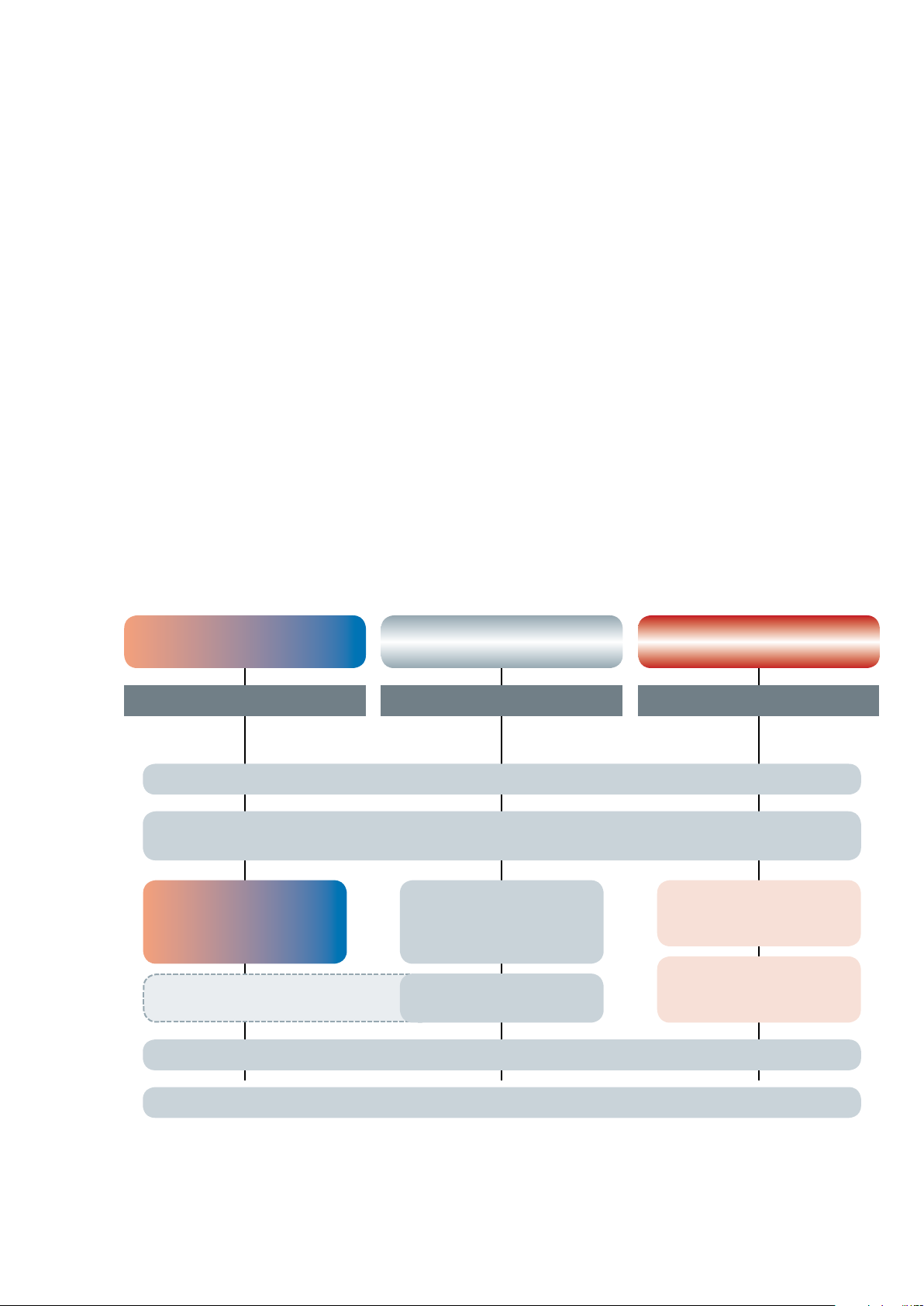
procedure according to your personal preferences and the clinical situation:
– IPS InLine One: Uncomplicated one-layer ceramic for quick and efficient layering
– IPS InLine: Conventional metal-ceramic for traditional, individualized layering
– IPS InLine PoM: Press-on-Metal ceramic for accurately fitting, fully anatomical press-on procedures
The IPS InLine System gives you the choice without increasing the number of components. Join in a new
way to process metal-ceramic.
®
InLine
IPS
Conventional metal-ceramic
InLine® PoM
IPS
Press-on-Metal ceramic
IPS InLine
IPS InLine
InLine One
IPS
One = One-Layering PoM = Press-on-Metal
one -la yer m eta l-c era mic
7 One Dentcisals
con ven tio nal m eta l-c era mic pre ss ce ram ic
ALLOYS FROM IVOCLAR VIVADENT
IPS InLine System Opaquer (Paste)
IPS InLine System Opaquer (Powder)
InLine
IPS
Dentin
Incisal
Margin
Deep Dentin
IPS InLine Impulse
IPS InLine Gingiva
InLine PoM
IPS
7 PoM ingots
7 PoM Touch Ups
IPS InLine System Shade / Stains / Glaze
IPS InLine System Add-On (690°C/1274°F)
2
Page 3

Table of Contents
5 Product Information
IPS InLine System – Metal-Ceramic System
IPS InLine One – One-Layer Metal-Ceramic
IPS InLine – Conventional Metal-Ceramic
IPS InLine PoM – Press-On Metal-Ceramic
pr o d uct
in f o rma t i on
Composition
Coordinated Ivoclar Vivadent Alloys
Preparation Guidelines and Minimum Layer Thicknesses
11 IPS InLine One
Framework design criteria
Step-by-step IPS InLine One
Framework design
Alloy processing / oxide firing
Layering diagram IPS InLine One
Oqaquer firing
– Paste opaquer
– 1st Opaquer firing (wash firing)
– 2nd Opaquer firing
– Powder opaquer
– 1st Opaquer firing (wash firing)
– 2nd Opaquer firing
Individual processing
Stain and characterization firing
Shade adjustment with IPS InLine Shade and Stains
Glaze firing
Add-On after glaze firing
27 IPS InLine
Framework design criteria
Step-by-step IPS InLine
Framework design
Alloy processing / oxide firing
Layering diagram IPS InLine
Oqaquer firing
– Paste opaquer
– 1st Opaquer firing (wash firing)
pr a c tic a l pr o c edu r e fo r met a l -su p p ort e d re s t ora t i ons
– 2nd Opaquer firing
– Powder opaquer
– 1st Opaquer firing (wash firing)
– 2nd Opaquer firing
IPS InLine Opaquer F (optional)
1st and 2nd Margin firing (optional)
1st Dentin and Incisal firing
2nd Dentin and Incisal firing
Margin Add-On firing
Add-On material firing
Individual processing
Stain and Characterization firing
Shade adjustment with IPS InLine Shade and Stains
Glaze firing
Add-On after glaze firing
3
Page 4

46 IPS InLine PoM
Framework design criteria
Step-by-step IPS InLine PoM
Framework design
Alloy processing / oxide firing
Layering diagram IPS InLine PoM
Oqaquer firing
– Paste opaquer
– 1st Opaquer firing (wash firing)
– 2nd Opaquer firing
– Powder opaquer
– 1st Opaquer firing (wash firing)
– 2nd Opaquer firing
IPS InLine Opaquer F (optional)
Wax-up
Sprueing
Investing
Preheating
Ingot selection
Pressing with the 100g, 200g, 300g IPS investment ring system
Divesting
Separating / finishing
Adjustements with IPS InLine PoM Touch-Up
Individual finishing
Stain and Characterization firing
Shade adjustment with IPS InLine Shade and Stains
Glaze firing
Add-On Glaze firing
procedure
rations
practical
for metal-free resto-
in f o rma t i on
70 IPS InLine Veneers
Fabricating the model (refractory die model)
Wash firing
Cervical firing
Dentin / Impulse firing
Incisal firing
Glaze firing
Divesting the veneers
Conditioning the veneers for adhesive cementation
72 General Information
Cementation
IPS InLine One firing parameters
IPS InLine firing parameters
IPS InLine PoM Mixing ratio investment material / press parameters / firing parameters
IPS InLine Veneer firing parameters
Combination Tables
4
Page 5
Product Information
InLine
IPS
InLine
IPS
®
One – one-layer metal-ceramic
®
– conventional metal-ceramic
Material
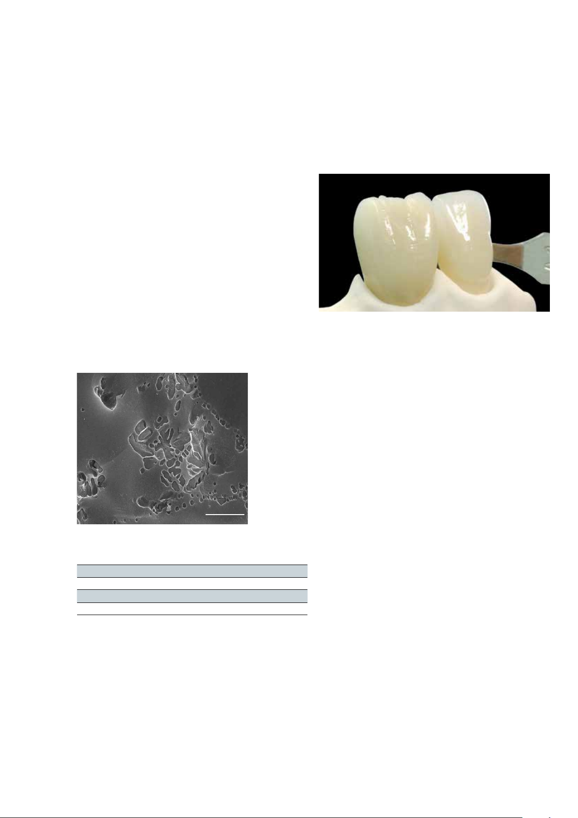
IPS InLine and IPS InLine One are veneering ceramic materials
containing leucite. They are suitable for the fabrication of metalceramic restorations at firing temperatures higher than 900 °C
(1652 °F). With both products, alloys in the CTE range of
13.8–15.0 x 10⁻⁶/K-1 (25–500°C) can be veneered, irrespective of the
metal composition. These ceramics are based on leucite-forming
glasses, some of which are produced of feldspar raw materials of a
natural origin. Given their composition they demonstrate excellent
chemical resistance. With the corresponding mixture and targeted
heat treatment of these glasses, leucite crystals with a defined grain
size distribution are released in the glass matrix. This results in a
homogeneous structure for the veneering material, which is not only
extremely gentle to antagonist but also provides the high strength
and convincing optical properties of the IPS InLine veneering ceramic
materials.
5 µm
IPS InLine Deep Dentin, IPS InLine Dentin, IPS InLine Transpa Incisal,
IPS InLine Gingiva, IPS InLine One Dentcisal:
CTE (25 – 500°C) [10-6 /K]1) 12.9 ± 0.5
Flexural strength (biaxial) [MPa]
Chem. solubility [μg/cm
Firing temperature [°C] 900 – 930
1)
according to ISO 6872:2008
2)
typical mean value for the flexural strength is 80 MPa
Classification: Dental ceramics Type 1 / Class 1
1) 2)
≥ 50
2]1)
≤ 100
Indications
– One-layer veneering ceramic for the most popular dental alloys in
the CTE range of 13.8 – 15.0 x 10⁻⁶/K (25 – 500°C) (IPS InLine One)
– Conventional multi-layer veneering ceramic for the most popular
dental alloys in the CTE range of 13.8 – 15.0 x 10⁻⁶/K (25 – 500°C)
(IPS InLine)
– Veneers on refractory die material (only IPS InLine)
Contraindications
– If patients are known to be allergic to any of the ingredients, the
material should not be used.
– Bruxism
– Veneering of titanium and zirconium oxide frameworks
– Any other use not listed in the indications
Important processing restrictions
– Exceeding or falling short of the stipulated veneering layer
thicknesses
– Failure to observe the layer thickness ratio between the framework
and layering ceramic
– Mixing with and processing in conjunction with other dental
ceramics
– Veneering of dental alloys not within the stipulated CTE range
– Failure to observe the necessary minimum connector and frame-
work thicknesses
Side effects
If patients are known to be allergic to any of the components in the
materials, IPS InLine One and IPS InLine restorations should not be
used.
5
Page 6
InLine
IPS
®
PoM – Press-on-Metal ceramic
Material
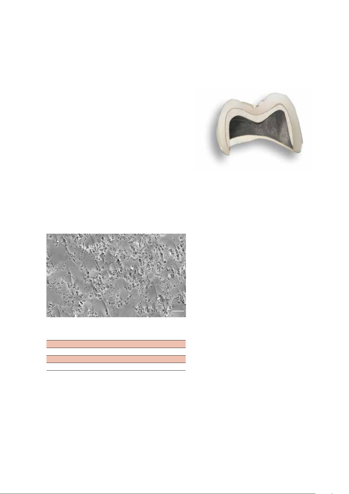
The IPS InLine PoM ingots are made of a glass-ceramic material
containing leucite and based on synthetic glass raw materials, which
contain small quantities of an opalescent glass-ceramic in addition to
the translucent components. This provides the ingots pressed to full
contour with their highly esthetic appearance. The ingots are shaded
with pigments, the temperature resistance of which permits the high
shade match of the pressed restorations. Both in their pressed and
unpressed condition, the ingots demonstrate an iso-tropic structure,
which is responsible for its homogeneous distribution of the leucite
crystals and the high strength. Another important feature of
IPS InLine PoM is its excellent firing stability, which enables the
application of Touch-Up materials, Shade, Stains and Glaze without
jeopardizing the accuracy of fit of the restoration. The Touch-Up
materials are leucite glass-ceramics shaded according to the ingot
shade concept. Their thermal expansion and firing temperature are
adjusted to suit the application in the cervical area of the ingot after
pressing and before the characterization firing cycles.
Indications
– Fully anatomical pressing on masked (opaquerized) crown and
bridge metal frameworks
– Pressing on dental alloys with a CTE range of 13.8–14.5 x 10⁻⁶/K
(25–500°C) with a silver content of <10%
IPS InLine PoM ingots:
CTE (25 – 500°C) [10-6 /K]1) 13.2 ± 0.5
Flexural strength (biaxial) [MPa]
Chem. solubility [μg/cm
Press temperature [°C] 940 – 950
1)
according to ISO 6872:2008
2)
typical mean value for the flexural strength is 130 MPa
Classification: Dental ceramics Type II / Class 1
1) 2)
≥ 50
2]1)
≤ 100
10 µm
Contraindications
– Pressing on dental alloys with a CTE outside the stipulated range
and not featuring the defined composition
– Alloys with a silver (Ag) content higher than 10%.
– If patients are known to be allergic to any of the ingredients, the
material should not be used.
– Pressing on titanium and zirconium oxide frameworks
– Very deep sub-gingival preparations
– Patients with substantially reduced residual dentition
– Bruxism
– Any other use not listed in the indications
Important processing restrictions
– Exceeding or falling short of the stipulated layer thicknesses for
press ceramics
– Failure to observe the layer thickness ratio between the framework
and layering ceramics
– Failure to observe the necessary minimum connector and frame-
work thicknesses
– Layering with IPS InLine One / IPS InLine layering materials (e.g.
Dentcisal, Dentin, Incisal, Deep Dentin, Margin, Impulse and
Gingiva materials, etc.)
– Mixing with and processing in conjunction with other dental
ceramics
– Pressing over dental alloys not within the stipulated CTE range
Side effects
If patients are known to be allergic to any of the components in the
materials, IPS InLine PoM restorations should not be used.
6
Page 7

Composition
IPS InLine One IPS InLine IPS InLine PoM
– IPS InLine One Ceramic Materials
Leucite ceramic based on alcalialumo
silicate glasses and feldspar
– IPS InLine System Shade / Stains / Glaze
Ceramic materials and glycols
– IPS InLine System Build-Up Liquids L and P
Water, glycols and additives
– IPS InLine Ceramic Materials
Leucite ceramic based on alcalialumo
silicate glasses and feldspar
– IPS InLine Margin Build-Up Liquid
Water and cellulose derivative
– IPS Model Sealer
Ethyl acetate, nitro-cellulose, softener
– IPS Ceramic Separating Liquid
Paraffin oil
– IPS InLine PoM Ingots
Leucite ceramic based on alcalialumo
silicate glasses
– IPS InLine PoM Touch-Up Materials
Leucite ceramic based on alcalialumo
silicate glasses
– IPS e.max AlOx Plungers
Al
2O3
– IPS e.max AlOx Plunger Separator
Boron nitride
– IPS PressVEST Powder
SiO2 (quartz powder), MgO and NH4H2PO4
– IPS PressVEST Liquid
Colloidal silicic acid in water
– IPS PressVEST Speed Powder
SiO2 (quartz powder), MgO and NH4H2PO4
– IPS PressVEST Speed Liquid
Colloidal silicic acid in water
– IPS InLine System Powder Opaquer Liquid
Water, glycols, acetic acid, additives
– IPS InLine System Opaquer Liquid
Butylene glycol, glycerine, thickening agent
– IPS InLine System Glaze and Stains Liquid
Butandiol
– IPS Margin Sealer
Wax dissolved in hexane
Warning
– Hexane is highly flammable and detrimental to health. Avoid contact of the material with skin and eyes. Do not inhale vapours. Keep
away from sources of ignition.
– Avoid inhaling grinding dust when working on ceramic restorations. Use suction equipment or protective masks.
7
Page 8
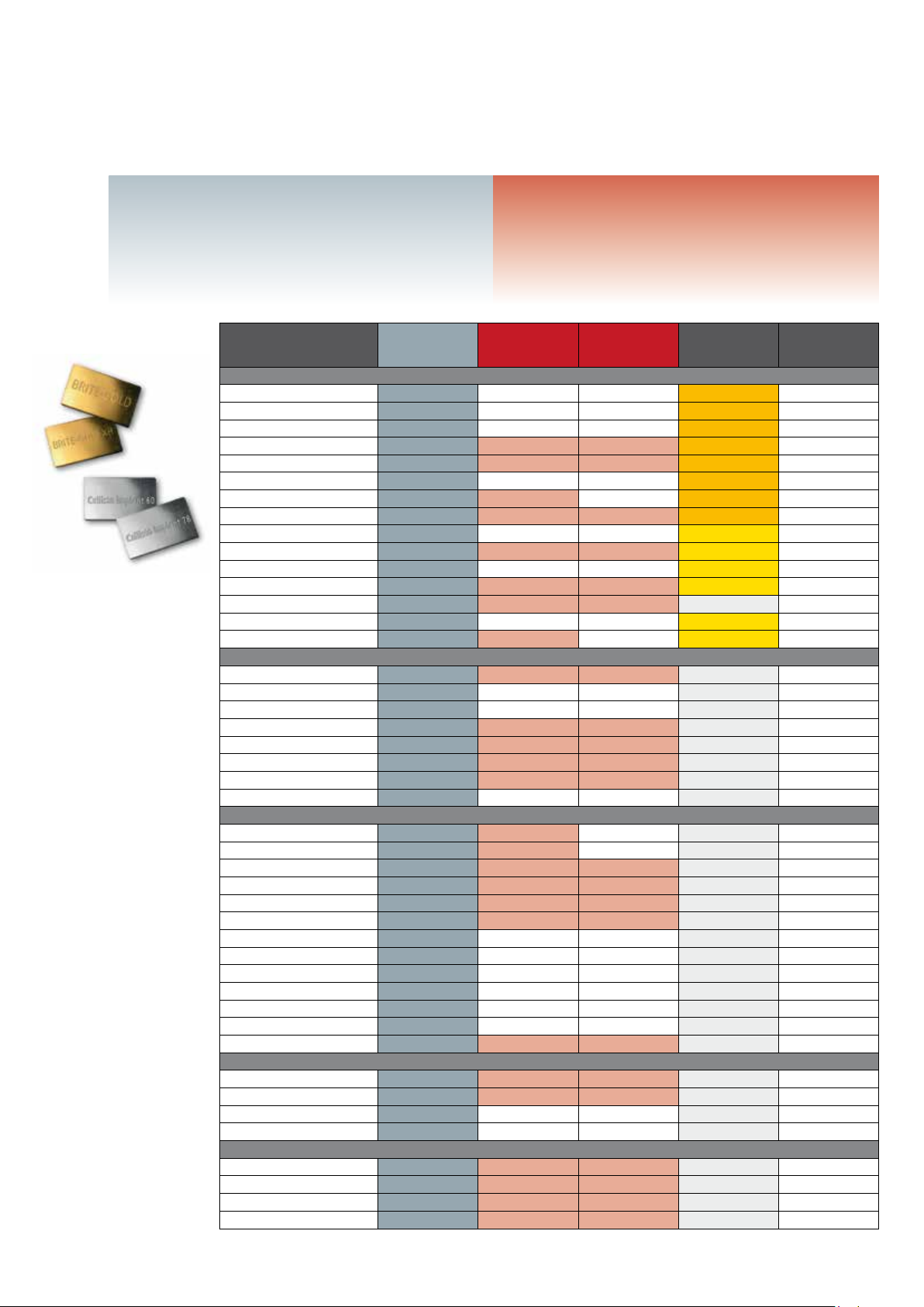
Coordinated Ivoclar Vivadent alloys
IPS InLine One, IPS InLine ...
are suitable for alloys with a CTE of approximately 13.8 to
15.0 x 10⁻⁶/K at 25–500 °C. If the required framework design
with metal scallops (as described on page 25) and the ceramic
layer thickness of max. 1.5 mm are observed, these alloys may be
processed using standard cooling in the Programat® furnaces.
Alloy
High gold
Brite Gold
Brite Gold XH
Golden Ceramic
Callisto 86
Aquarius Hard
Aquarius
d.SIGN 98
Callisto 84
Y
Aquarius XH
Y-2
Y-Lite
Sagittarius
Y-1
d.SIGN 96
Reduced gold
d.SIGN 91
W
W-5
Lodestar
W-3
Leo
W-2
Evolution Lite
Palladium content
Spartan Plus
Spartan
Capricorn
d.SIGN 84
Protocol
Callisto 75 Pd
Aries
d.SIGN 67
d.SIGN 59
d.SIGN 53
W-1
Capricorn 15
Callisto CPG
Implant alloys
Callisto Implant 78
Callisto Implant 33
IS-64
Callisto Implant 60
Free of precious metals
Colado NC
4all
d.SIGN 30
Colado CC
IPS InLine One
IPS InLine
✓* –
✓*
✓* –
✓ ✓ ✓
✓* ✓
✓*
✓* ✓
✓ ✓ ✓
✓
✓ ✓ ✓
✓* – –
✓ ✓ ✓
✓ ✓ ✓
✓*
✓ ✓ –
✓ ✓ ✓
✓ –
✓ –
✓ ✓ ✓
✓ ✓ ✓
✓ ✓ ✓
✓ ✓ ✓
✓ –
✓ ✓
✓ ✓
✓ ✓ ✓
✓ ✓
✓ ✓
✓ ✓ ✓
✓ –
✓ –
✓*
✓** –
✓* –
✓ –
✓ ✓ ✓
✓ ✓ ✓
✓ ✓ ✓
✓** –
✓** –
✓ ✓ ✓
✓ ✓
✓** ✓
✓** ✓
* Cooling to 800 °C / 1472 °F
** Cooling to 700 °C / 1292 °F
8
IPS InLine PoM ...
is suitable for pressing on alloys with a CTE of 13.8 to 14.5 x 10⁻⁶/K
at 25–500 °C and with a maximum silver content of 10 %.
IPS InLine PoM
IPS Investment Ring
100/200 g
– –
2)
– –
1)
– –
– –
2)
2)
– –
2)
✓ 2)
2)
✓ 2)
2
1) Single restorations
2) see ”Important” next page
IPS InLine PoM
IPS Investment Ring
300 g Colour
–
–
2)
✓
–
–
–
–
–
–
2)
✓
2)
✓
–
–
–
–
–
–
–
2)
✓
The range of available alloys may vary from country to country.
rich yellow 14.8
rich yellow 14.4
rich yellow 14.6
rich yellow 14.4
rich yellow 14.5
rich yellow 14.6
rich yellow 14.3
rich yellow 14.3
yellow 14.6
yellow 14.1
yellow 15.0
yellow 13.9
white 14.0
yellow 14.8
yellow 14.3
white 14.2
white 14.2
white 14.0
white 14.1
white 13.9
white 13.9
white 14.2
white 14.2
white 14.3
white 14.2
white 14.1
white 13.8
white 13.8
white 13.9
white 14.7
white 13.9
white 14.5
white 14.8
white 15.2
white 14.3
white 14.2
white 13.9
white 14.0
white 14.8
white 14.5
white 14.0
white 13.8
white 14.5
white 14.2
25–500°C
CTE
Page 9

Important
IPS InLine One, IPS InLine
– If these minimum requirements cannot be observed, cooling to *800 °C, or **700 °C (depending on
the alloy type), is required in conjunction with all main firings and glaze firings.
– With ceramic layer thicknesses of over 1.5 mm up to max. 2.5 mm, as well as with voluminous resto-
rations (e.g. implant-retained reconstructions) in combination with high gold and base metal alloys,
cooling to *800 °C or ** 700 °C must be conducted. This also applies to soldered restoratios.
Important
IPS InLine PoM
– With alloys in the lower CTE range of 13.8 x 10⁻⁶/K at 25–500 °C and the upper range of
14.5 x 10⁻⁶/K at 25–500 °C, no ceramic shoulders should be used. With such framework geometries
(shoulder) or non-metal-supported areas, the cooling and tension conditions are critical. For ceramic
shoulders, alloys in the CTE range of approximately 14.0 to 14.3 x 10⁻⁶/K at 25–500 °C are
recommended.
– For single restorations – particularly with ceramic shoulders – only the 200g or 300g investment rings
should be used, since the expansion values as well as the cooling and tension conditions are ideally
coordinated.
Important
IPS InLine System Powder Opaquer
– Alloys (CTE of approx. 13.8 to 15.0 x 10⁻⁶/K at 25–500 °C) with a solidus point of ≥ 1080 °C are
suitable for opaquerizing with the powder opaquer at a firing temperature of 960 °C.
9
Page 10
Preparation guidelines and minimum layer thicknesses
2.0
>1.2
1.5
1.5
>1.2
1.5
>1.2
1.5
2.0 2.0
1.5
>1.2
>1.2
6°
1.5
1.5
2.0 2.0
1.5
>1.2
>1.2
6°
1.5
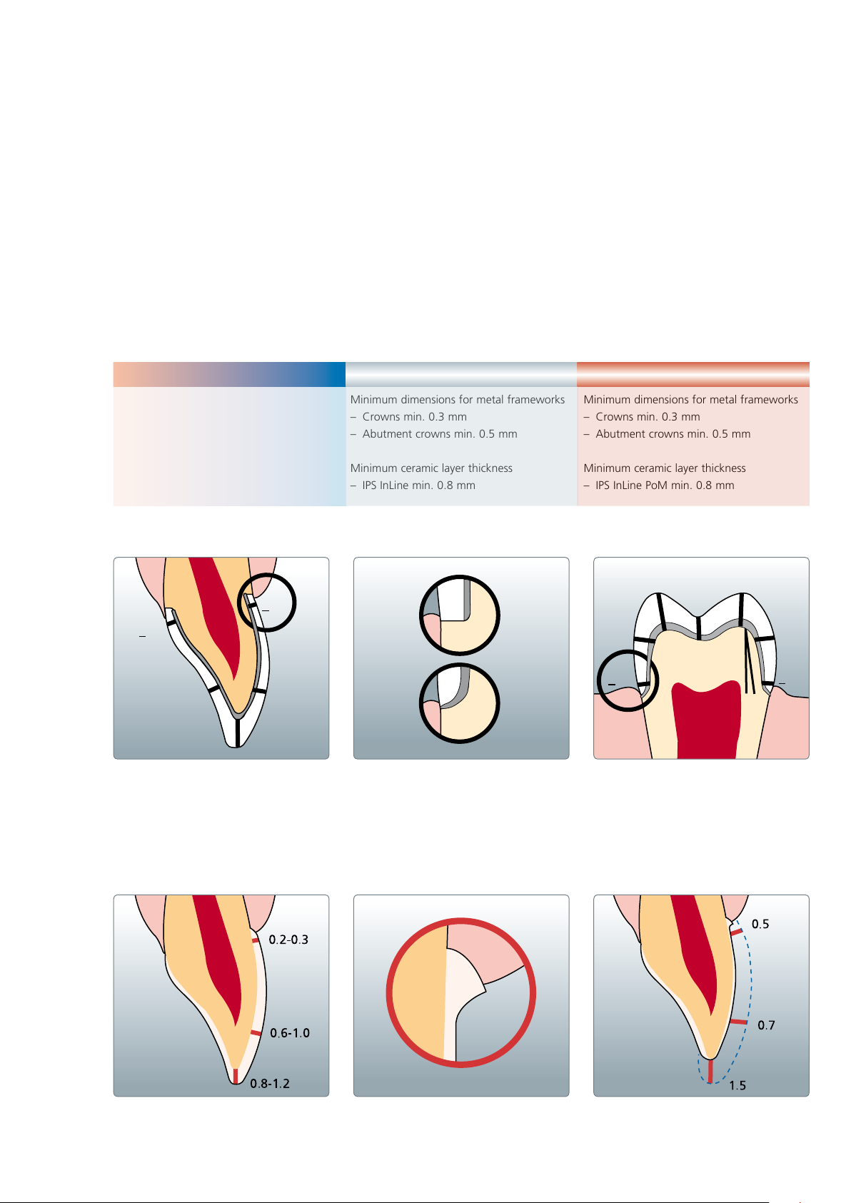
The preparation must provide sufficient space to achieve stable and esthetic metal-ceramic restorations. The usual preparation guidelines for
metal-ceramics apply for the IPS InLine System. As usual for metal-supported restorations, dentists may use conventional cementation.
A chamfer preparation is suitable for tapered metal margins. For metal-supported inlays, partial crowns and inlay-retained bridges that are
seated using conventional cementation, a chamfer preparation is indicated to minimize the cement gap. The margin is designed in metal.
For esthetically pleasing single crowns and bridge abutment crowns, a ceramic shoulder should be provided. For that purpose, a shoulder
preparation is required. With adhesive cementation, the margin can be designed in the ceramic. However, the margin should not be bevelled
in such cases, since thin, non-metal-supported margins demonstrate a fracture risk.
IPS InLine One
One-layer metal-ceramic
Minimum dimensions for metal frameworks
– Crowns min. 0.3 mm
– Abutment crowns min. 0.5 mm
Minimum ceramic layer thickness
– IPS InLine One min. 0.8 mm
IPS InLine
Conventional metal-ceramic
Minimum dimensions for metal frameworks
– Crowns min. 0.3 mm
– Abutment crowns min. 0.5 mm
Minimum ceramic layer thickness
– IPS InLine min. 0.8 mm
IPS InLine PoM
Press-on-Metal ceramic
Minimum dimensions for metal frameworks
– Crowns min. 0.3 mm
– Abutment crowns min. 0.5 mm
Minimum ceramic layer thickness
– IPS InLine PoM min. 0.8 mm
– With conventional cementation, a minimum height of 3 mm of the prepared tooth and a convergence angle of approx. 6° must be
observed.
– The following minimum connector dimensions should be observed for bridge restorations: The connector dimensions depend on the
selected alloy and the pontic width (see Framework Design Guidelines, page 9).
Veneers on refractory die material
10
Dimensions in mm
Page 11
®
InLine
IPS
One – one-layer metal-ceramic
Framework design criteria
The framework design is key to the success of durable metal-ceramic restorations. The more attention given to the framework
design, the better the final results and the clinical success will turn out to be.
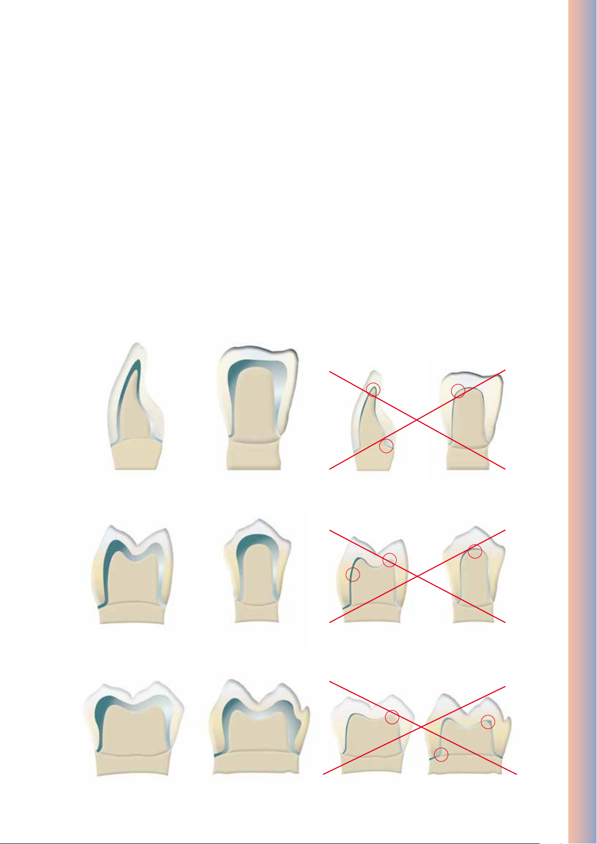
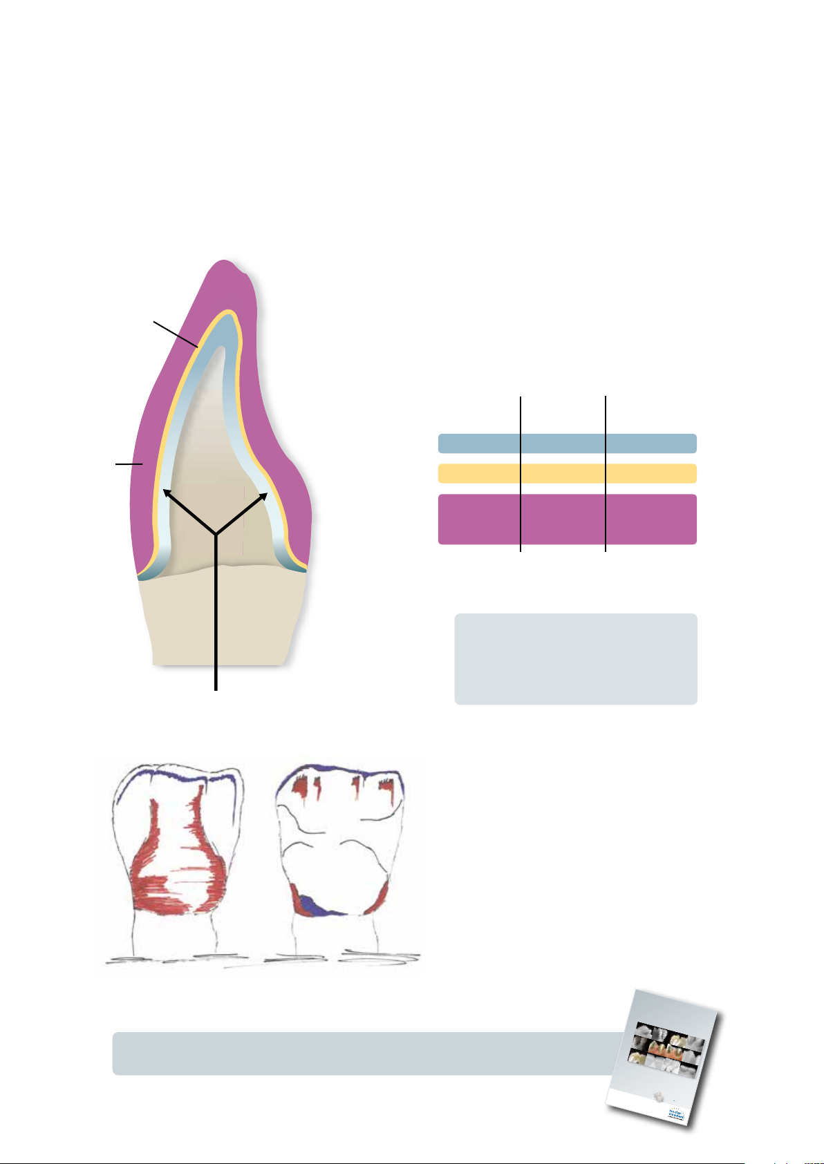
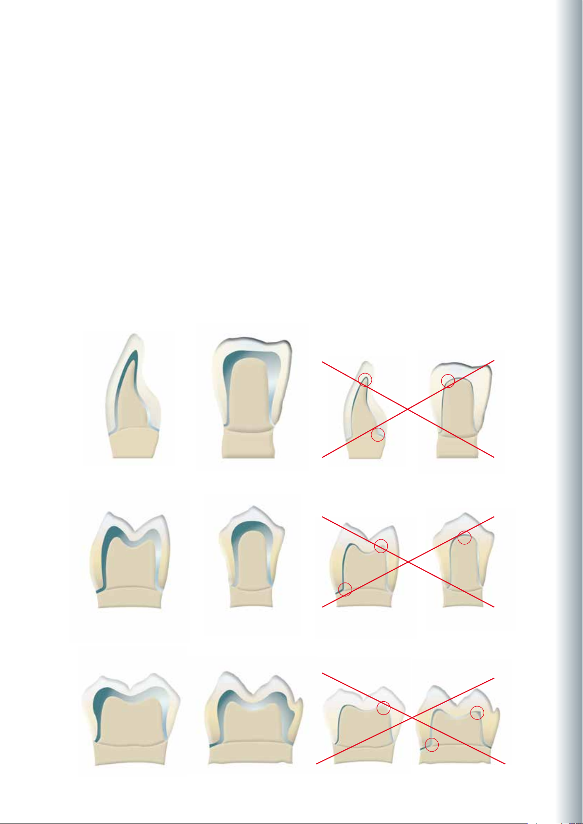
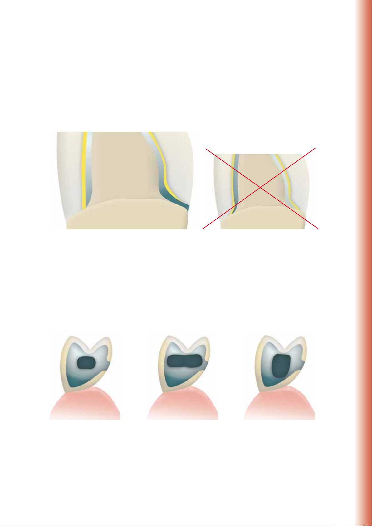
1. Functional support of the veneering ceramic
The framework reflects the shape of the tooth in a reduced form. It should be designed in such a way that it supports the
cusps and incisal edges resulting in a virtually even layer thickness of the veneering ceramic in the cusp-fissure area. In this
way, the masticatory forces occurring during functional chewing are exerted on the framework rather than on the veneering
ceramic. Therefore, the framework must not show any angles and edges (see diagram) so that the masticatory forces do not
result in tension peaks, which may cause delamination and cracks. Such angles and edges should already be rounded off in
the wax-up, not as late as in the metal. The wall thickness of the metal framework for single crowns must not be less than
0.3 mm and for bridge abutments 0.5 mm after finishing (see diagram). Please refer to the Instructions for Use of the
corresponding alloy for further information.
IPS InLine One – One-Layer Metal-Ceramic
Anterior crowns
Premolar crowns
correct
correct wrong
wrong
Molar crowns
correct wrong
11
Page 12
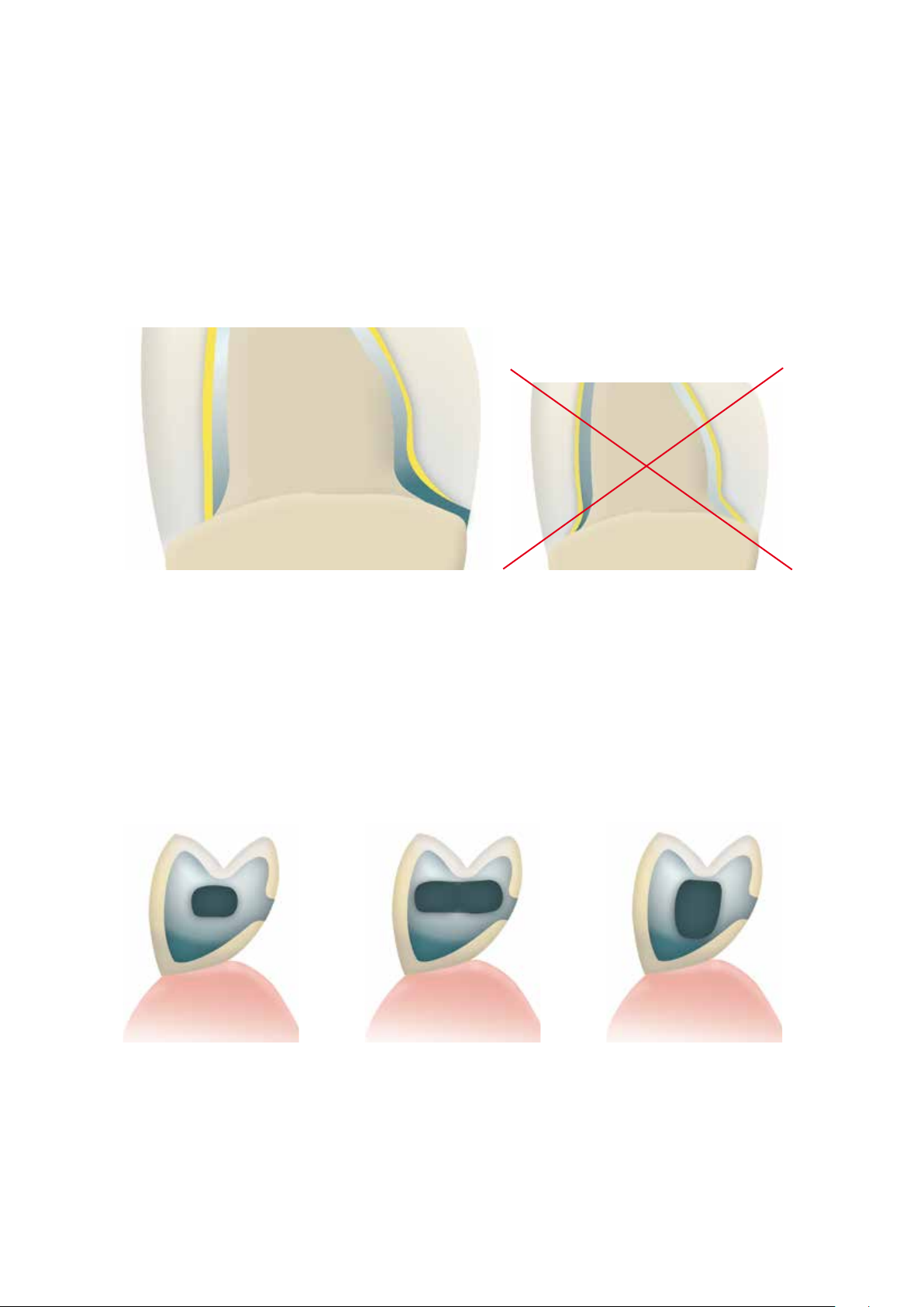
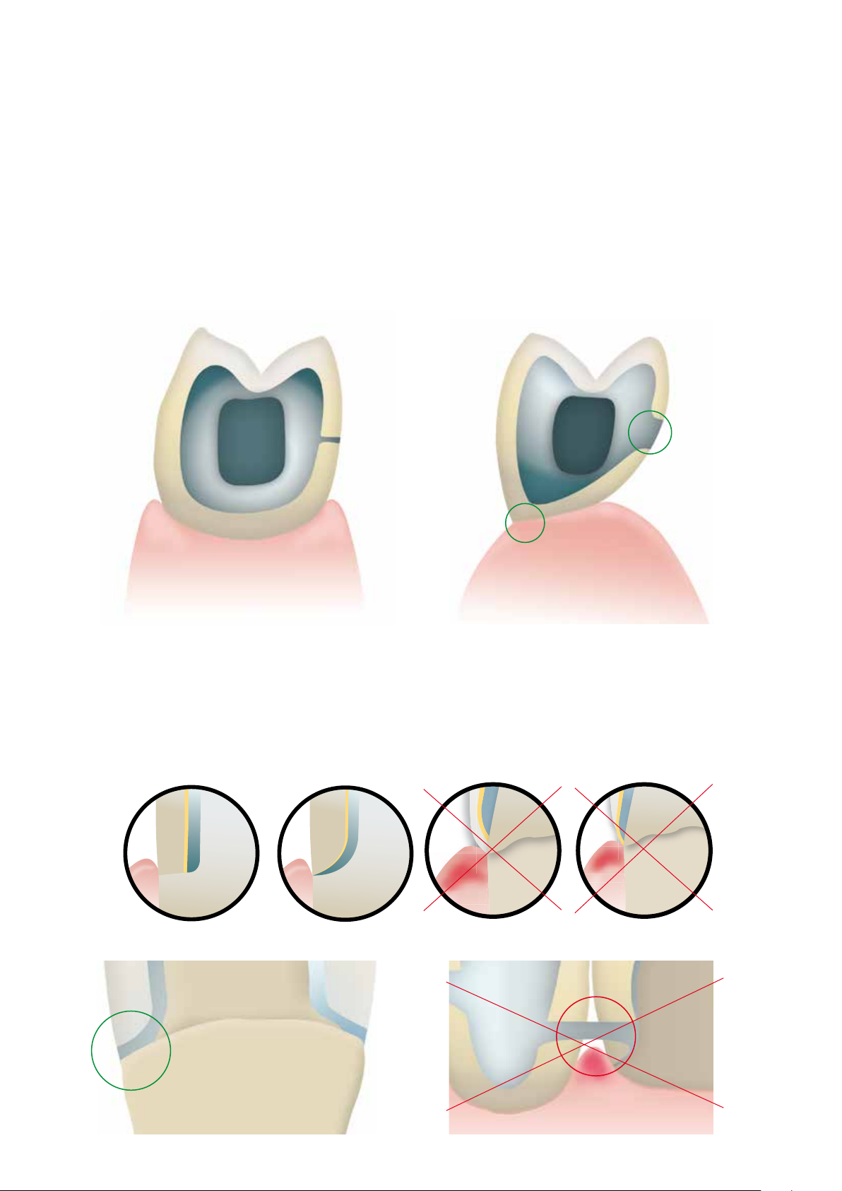
2. Framework design for fired ceramic shoulders
With fired ceramic shoulders, make sure that the framework rather than the veneer is supported by the prepared tooth.
The framework is thus reduced exactly to the inner edge of the chamfer or shoulder preparation to achieve functional
support of the framework on the preparation. Excellent accuracy of fit on the preparation is essential to ensure that the
shoulder material may not reach the inner aspects of the framework during subsequent application.
correct
wrong
3. Framework stability
The dimensions and shape of the interdental connector surfaces significantly influence the stability of the restoration
during processing as well as the clinical long-term success after incorporation. Therefore, the dimensions of the interdental
connector surface must be designed in accordance with the alloy used (take the 0.2% proof stress into account)! The
thermal behaviour of the selected alloy during processing has to be considered when designing the framework.
Single connector width
= single stability
Double the width of the
connector
= double the stability
12
Double the height of the
connector with single width
= eightfold stability
Page 13
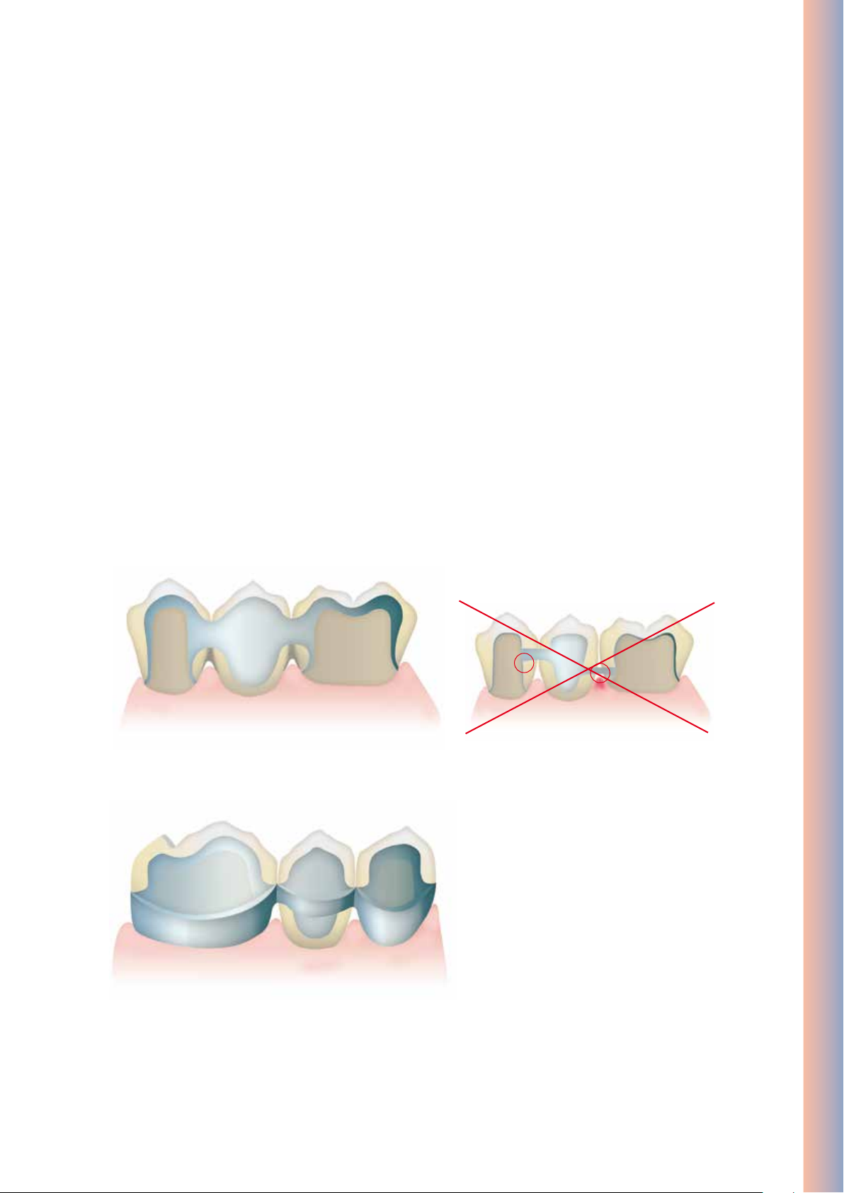
4. Framework design for bridges
Thermal stress during firing and masticatory forces after cementation affect metal frameworks. These forces must be
transferred on the framework rather than the veneer. Particularly in the connector areas between bridge abutments and
bridge pontics in bridge reconstructions, the stability must be ensured with the help of the framework design and
adequate framework material thickness. The framework design and framework thickness must therefore meet all the
optical and functional requirements, as well as the aspects of periodontal hygiene. A full wax-up with the corresponding
reduction of the ceramic provides the most predictable results.
During veneering with ceramic materials, the bridge framework is exposed to high temperatures several times. With an
inappropriate framework design or insufficient framework thickness, the high temperatures during firing may result in
distortion or inaccuracy of fit of the framework. A scallop-type design with e.g. interproximal reinforcements counteracts
this development. Additionally, this framework design (e.g. with cooling struts) ensures more even cooling of the
restoration during the cooling phase. This is particularly important for high gold alloys.
In order to enable optimum oral hygiene with bridge restorations, the design of the interdental spaces should be given
special attention. Adequate opening of the interdental area without creating black triangles should be given special
attention in order to ensure proper periodontal hygiene with interdental brushes and dental floss.
IPS InLine One – One-Layer Metal-Ceramic
correct
correct
wrong
13
Page 14
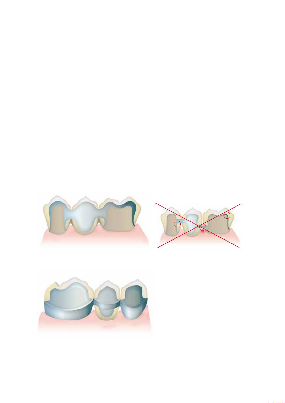
5. Design of bridge pontics
Bridge pontics are designed with esthetic and functional aspects as well as oral hygiene in mind. The area of the pontic
that contacts the alveolar ridge should be made of ceramic.
In order to ensure adequate stability between the bridge pontic and the bridge abutments, a palatal and/or lingual scallop
is recommended. Furthermore, to ensure even cooling of the bridge pontic that absorbs the most heat, additional
cooling struts are advantageous.
Bridge pontic design – ovate pontic Bridge pontic design – saddle-type pontic
6. Interface between metal and ceramic
The interface between the metal framework and the veneering ceramic must be clearly defined. If possible, incorporate a
right angle finish line. The junctures between the metal framework and the veneering ceramic must neither be located in
the contact area nor on surfaces involved in masticatory functions. The interface in the interdental area should be
designed in such a way that cleaning of these hard-to-reach areas is possible.
correct
correct
wrong
wrong
14
Page 15
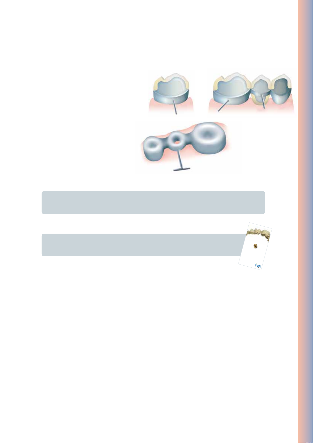
Holding pins
FRAMEWORK DESIGN
for
met a l
-
cer a mi c
res t or a ti o n s
Manual
In order not to damage the crown wall during
processing, the crown and bridge frameworks are
provided with holding pins. They are directly
attached to the framework with the help of wax.
Dimensions of Ø 0.5–1.0 mm for the holding pins
have proven to be useful. They can be used to
secure the framework by means of holding clips.
Furthermore, the holding pins also act as cooling
struts during casting and firing.
IPS InLine One – One-Layer Metal-Ceramic
Important
The holding pins must be placed in such a way that they do not interfere during try-in or in the articulator.
They should only be removed without causing overheating once the restoration has been completed.
Please refer to the “Framework Design Guidelines for Metal-Ceramic Restorations” for additional
information on framework design. They can be ordered from your Ivoclar Vivadent contact
address.
15
Page 16
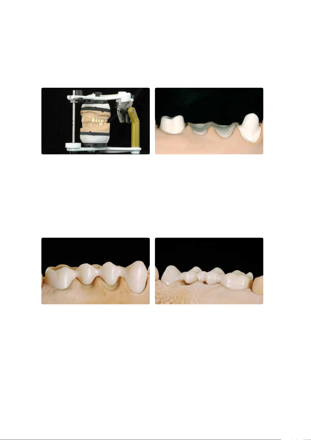
Step-by-step
Starting situation
Maxillary and mandibular model articulated in the “Stratos 200”
Starting situation for metal-supported IPS InLine restorations
Framework design
Design the framework with a reduced anatomical shape taking the planned layering into account. The wall thickness for
single crowns should be at least 0.3 mm and at least 0.5 mm for abutment crowns.
Make sure to provide sufficient stability of shape for the framework. Avoid sharp transitions and edges. Design the
connector areas between the individual units in such a stable way that they meet the requirements of interdental hygiene
and the alloy used.
Design the framework in a reduced supported shape.
16
Page 17
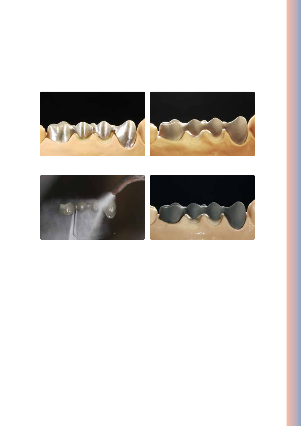
Alloy processing / oxide firing
The cast metal framework is finished using tungsten carbide burs or ceramic-bonded grinding instruments.
IPS InLine One – One-Layer Metal-Ceramic
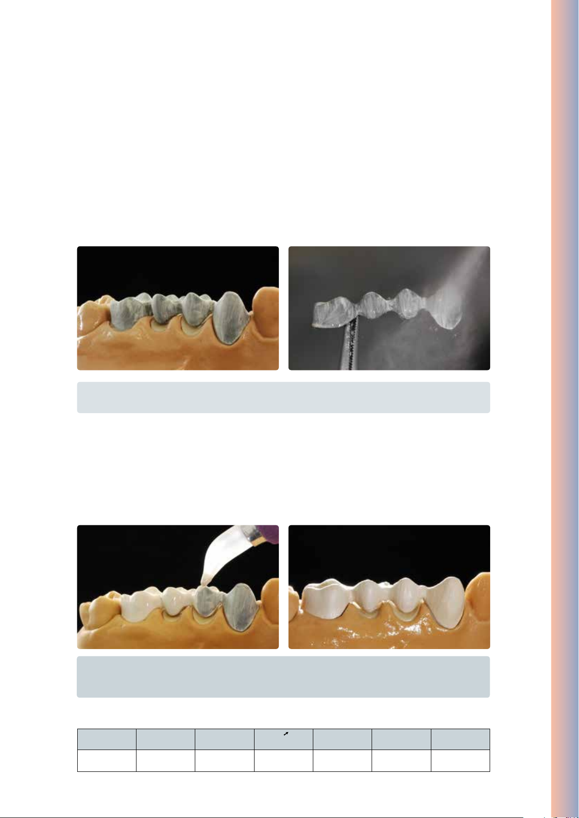
Metal framework before blasting Carefully blast the framework with aluminium oxide Al2O3 50–100 µm
After blasting, clean the metal framework with a steam jet and allow to dry thoroughly.
Conduct the oxide firing according to the instructions of the manufacturer.
After oxide firing, the framework should exhibit an evenly oxidized surface.
(observe the instructions of the alloy manufacturer).
17
Page 18
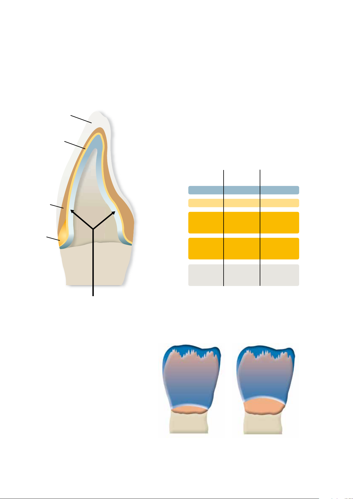
IPS InLine One layering diagram
Dieter Grübel
®
InLine PoM
IPS
Edition
LIEBE ZUM DETAIL –ÄSTHETIK UND MORPHOLOGIE
Press-on-Metal-Keramik
Opaquer
Dentcisal
Opalescence effect
Shade Incisal 1
Shade=Hue A1 etc…
Shade 1
Metal framework thickness:
– Crowns min. 0.3 mm
– Bridge abutments min. 0.5 mm
Chroma
Stains orange
Ideal layer
thickness
Framework
Opaquer
Dentcisal
cervical
incisal
These figures are drawn from past experience and they may vary in certain situations.
0.3–0.5 mm
0.1 mm
0.8 mm
1.5 mm
Limited layer
thickness
0.3–0.5 mm
0.1 mm
0.5 mm
0.8 mm
Note:
To enhance the chroma in thin layers, IPS InLine
Deep Dentin in the corresponding opaquer
shade may be thinly applied on the opaquer.
Halo effect
Stains vanilla
Mamelon effect
Stains vanilla,
Shade Incisal 1
Brightness value
Stains white
Depending on the desired
individualization, IPS InLine System
Shade/Stains can be used to
achieve true-to-nature shade
effects.
Chroma
Stains red
Shade Stains
You can find additional information on esthetic individualization in the edition “Love for
Detail” by D. Grübel. It can be ordered from your Ivoclar Vivadent contact address.
18
Page 19
Opaquer Firing
Paste opaquer
st
1
Opaquer firing (wash firing) (paste opaquer)
Select the IPS InLine System Opaquer paste in the corresponding tooth shade. If required, homogenize the opaquer paste
by stirring it before taking it from its jar. Extrude the desired amount from the syringe or jar and mix thoroughly on the
mixing pad. Thin it, if required. Apply the first opaquer layer thinly and agitate it into the alloy surface. After firing and
cooling, clean the opaquerized metal framework with the steam jet and dry with oil-free air.
IPS InLine One – One-Layer Metal-Ceramic
Tip:
The consistency of the paste opaquer can be individually adjusted using the IPS InLIne System Opaquer Liquid.
2nd Opaquer firing (paste opaquer)
Apply the second opaquer layer in such a way that the metal framework is entirely covered with opaquer. After firing, the
IPS InLine System Opaquer should show a covering, silky-mat shiny surface. After the opaquer firing, the conditioned
surfaces of the alloy framework should be entirely covered with opaquer.
Important
The firing tray with the opaquerized metal framework should only be placed in the firing chamber and
removed from it once the furnace head is completely open and the beeper has sounded.
Firing parameters IPS InLine System Opaquer (paste opaquer), 1
T
°C/°F
930/1706 403/ 757 6 100/180 2 450/842 929/1704
B
°C /°F
S
min
t
°C/°F/min
st
and 2nd Opaquer firing
H
min
19
V
1
°C/°F
V
°C/°F
2
Page 20
Powder opaquer
1st Opaquer firing (wash firing) (powder opaquer)
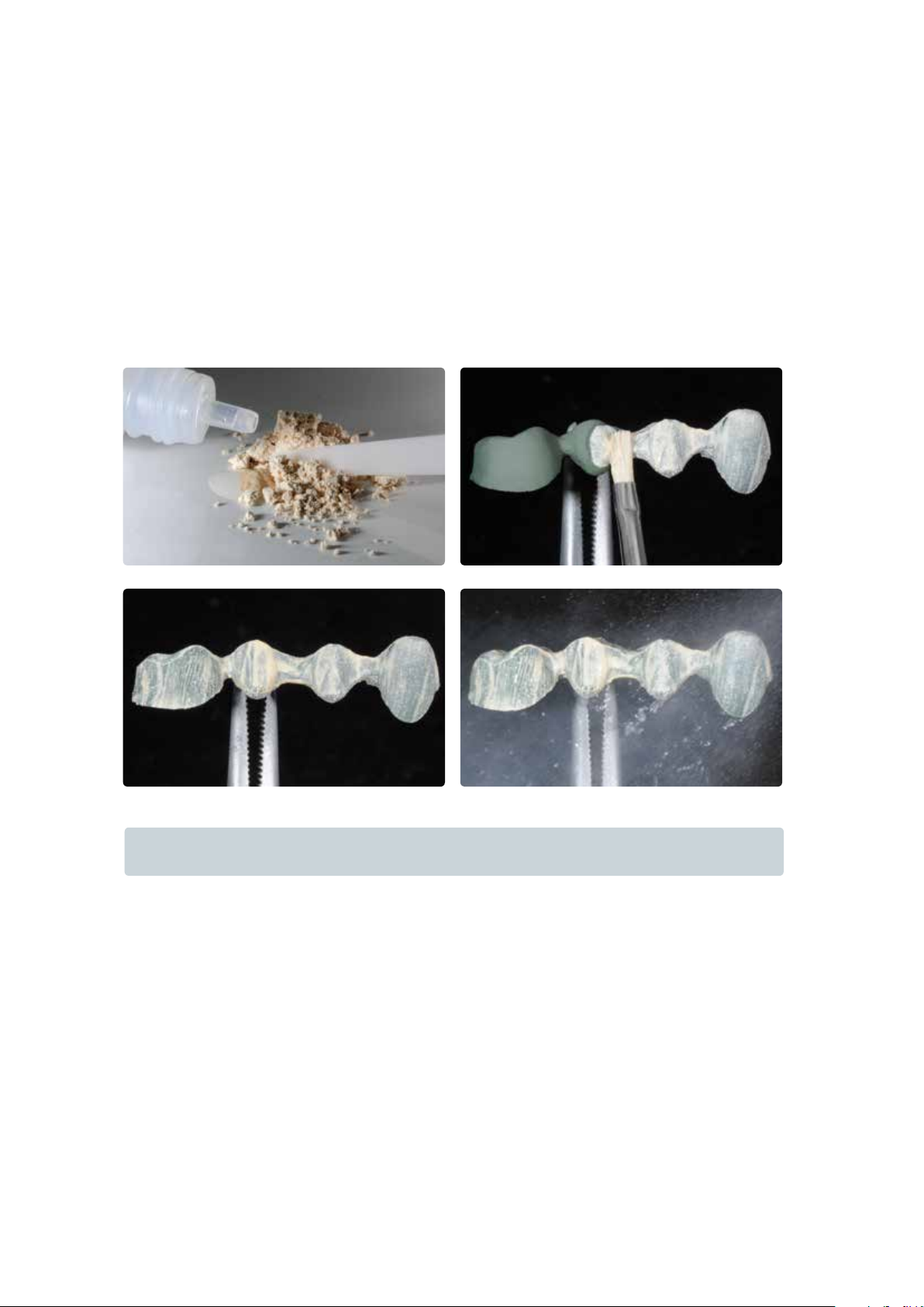
Select the IPS InLine System Powder Opaquer in the corresponding tooth shade. Remove the amount of powder opaquer
required for the wash from the jar and mix it thoroughly with the Powder Opaquer Liquid on the mixing pad until it has
reached the desired consistency. Apply the first opaquer layer thinly on the metal framework and agitate it into the alloy
surface. After firing and cooling, clean the opaquerized metal framework with the steam jet and dry with oil-free air.
Important
Mix IPS InLine System Powder Opaquer only with the Powder Opaquer Liquid.
20
Page 21
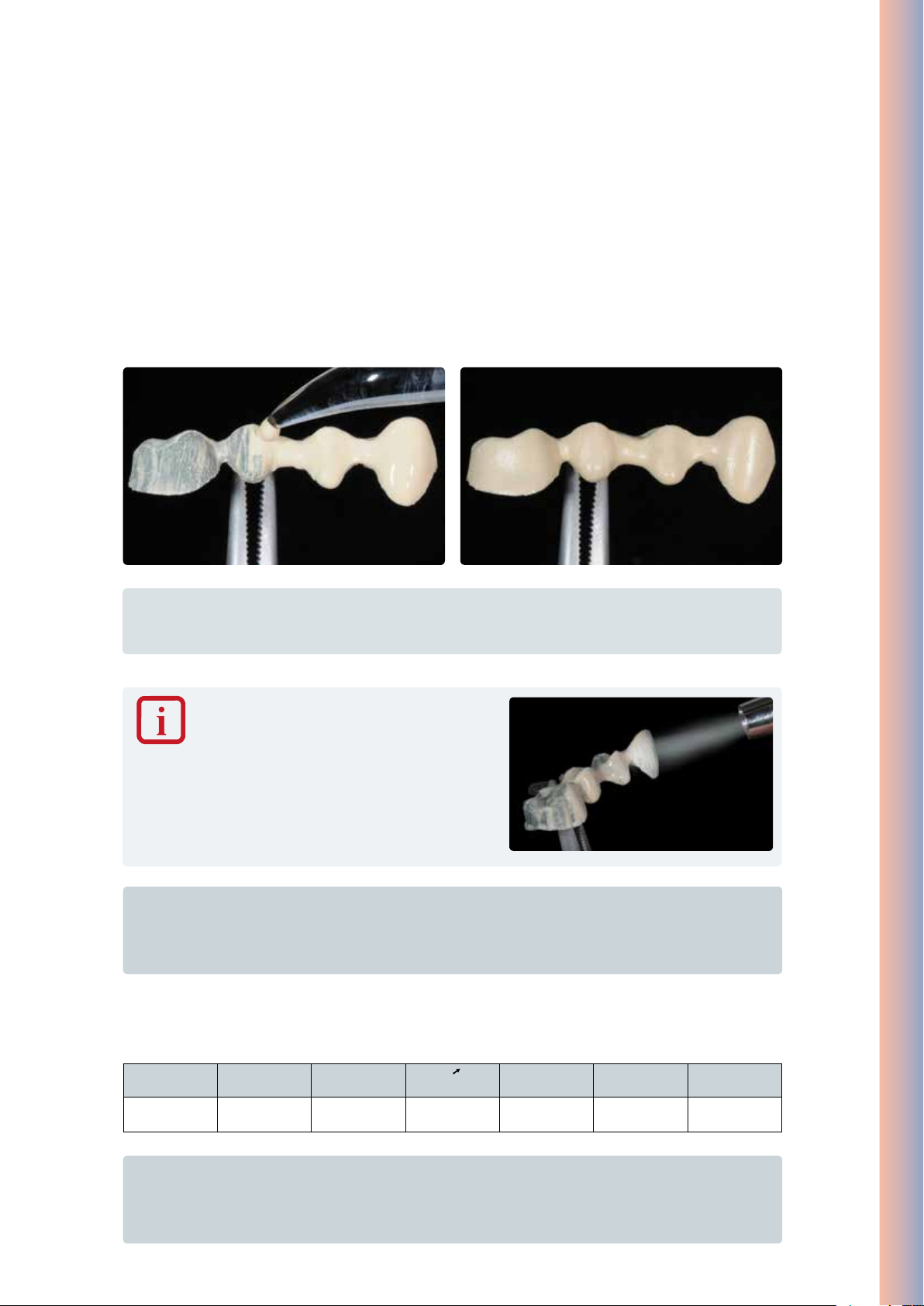
2nd Opaquer firing (powder opaquer)
Remove the amount of powder opaquer required for the covering layer from the jar and mix it together with the
remaining, dried up “wash opaquer” on the mixing pad. Then, mix the powder opaquer with the Powder Opaquer Liquid
until it has reached the desired consistency.
Apply the second opaquer layer evenly and in such a way that the metal framework is entirely covered with opaquer. After
firing according to the stipulated firing parameters, the IPS InLine System Powder Opaquer should show a covering, silkymat shiny surface. After the opaquer firing, the conditioned surfaces of the alloy framework should be entirely covered
with opaquer.
IPS InLine One – One-Layer Metal-Ceramic
Tip:
A glass or ceramic instrument is optimally suitable to apply the IPS InLine Powder Opaquer for the opaquer firing.
Naturally, a brush can also be used to apply IPS InLine Powder Opaquer.
The IPS InLine System Powder Opaquer and Powder
Opaquer Liquid are ideally suitable for the application
with conventional spray-on techniques. Mix the powder
opaquer to a thin consistency, depending on the sprayon system used. Observe the instructions of the
manufacturer of the spray-on systems.
Important
• Usedistilledwatertorewetthemixedorthealreadyappliedpowderopaquer.
• Thefiringtraywiththeopaquerizedmetalframeworkshouldonlybeplacedinthefiringchamberand
removed from it once the furnace head is completely open and the beeper has sounded.
Firing parameters IPS InLine System Opaquer (powder opaquer), 1
T
°C/°F
B
°C/°F
S
min
t
°C/°F/min
st
and 2nd Opaquer firing
H
min
V
1
°C/°F
V
2
°C/°F
960/1760 403/757 4 100/180 2 450/842 959/1758
Important
IPS InLine System Powder Opaquer
– Alloys (CTE of approx. 13.8 to 15.0 x 10⁻⁶/K at 25-500 °C) with a solidus point of ≥ 1080 °C are suitable for
opaquerizing with the powder opaquer at a firing temperature of 960 °C.
21
Page 22
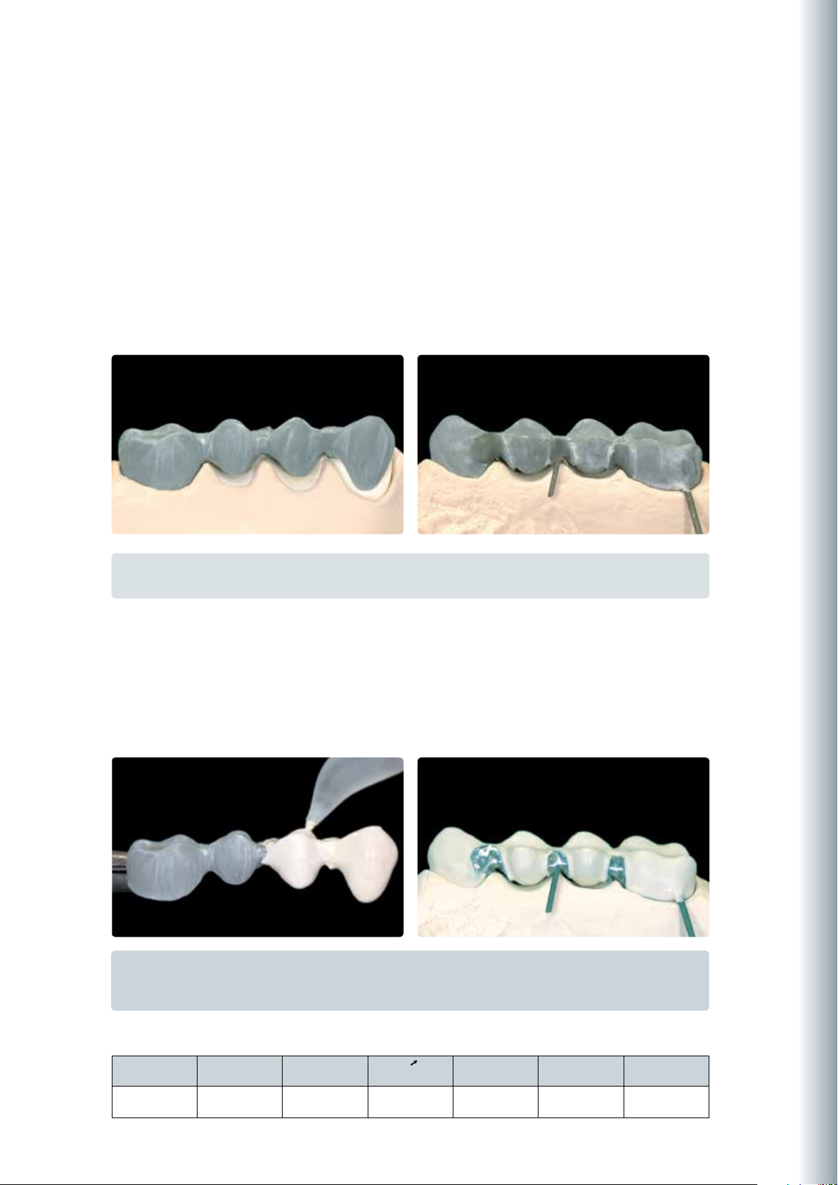
1st Dentcisal firing
Isolate the model before layering the Dentcisal material. In this way, the ceramic material is prevented from drying out or
sticking to the model. Isolate the stone die and the adjacent areas using IPS Model Sealer. Additionally,
separate the area of the pontics with IPS Ceramic Separating Liquid.
Tip:
To achieve an optimum bond between the ceramic material and the opaquer surface, apply a small amount of
IPS InLine One Dentcisal material to the cervical and interdental areas (for bridges) and slightly roughen it.
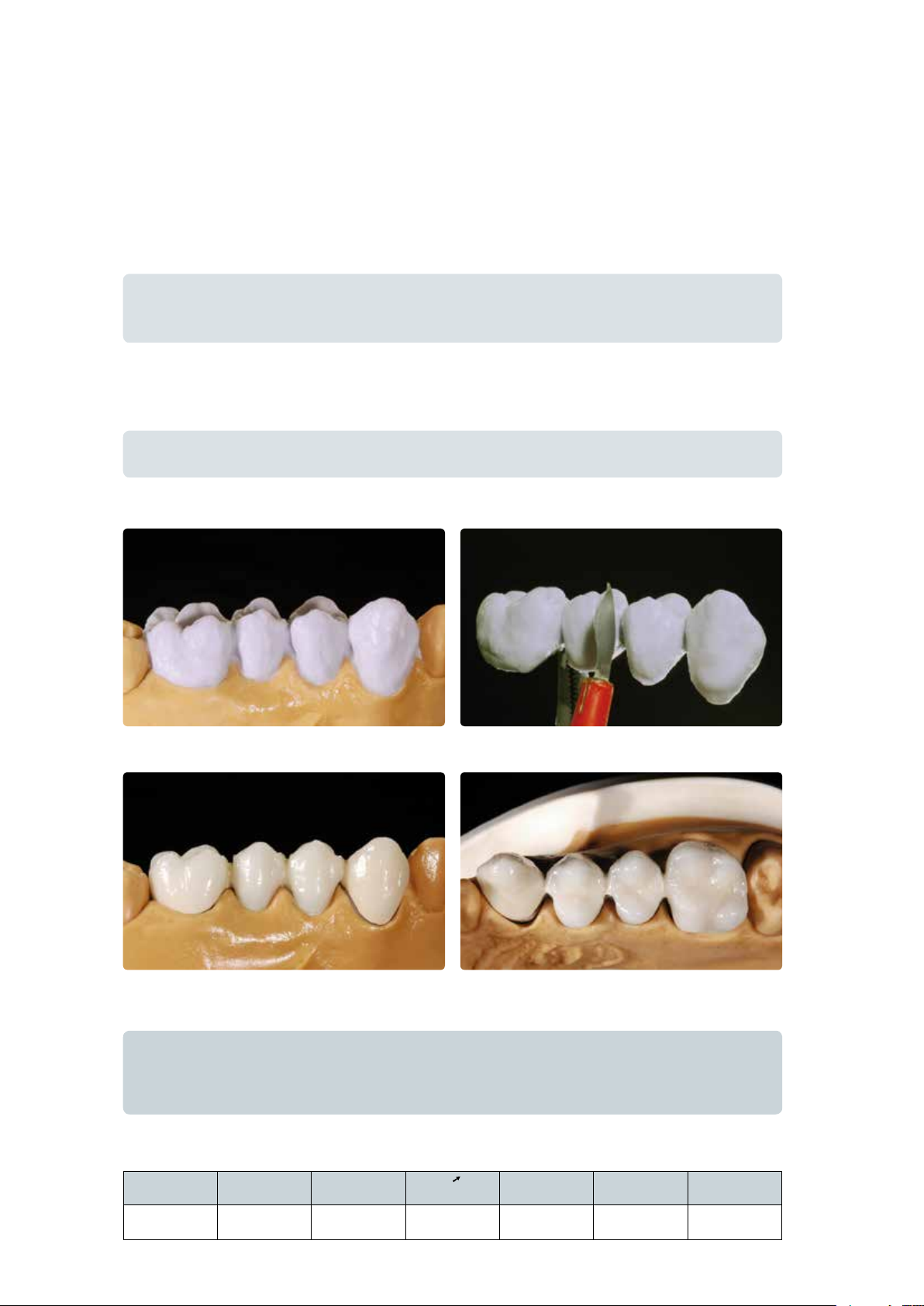
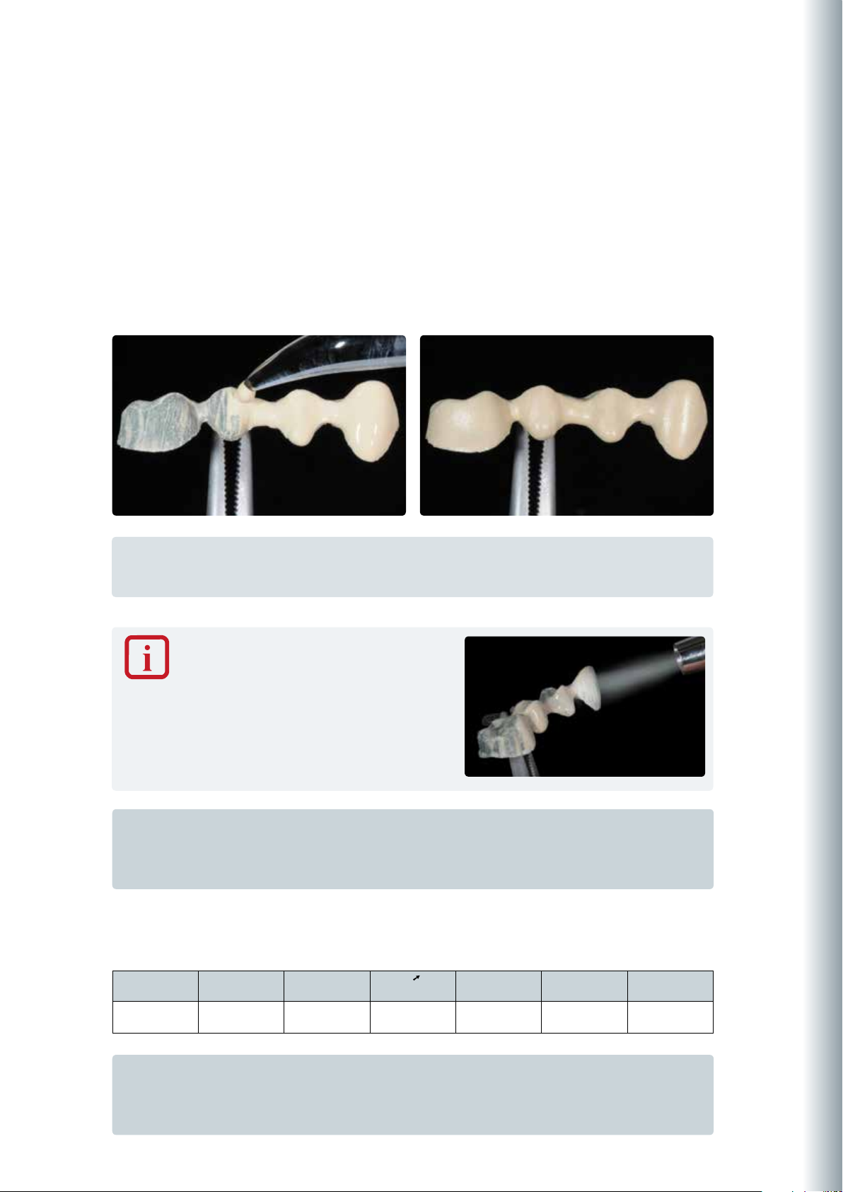
Make sure that the restoration is slightly overcontoured so that the actual tooth shape is achieved after firing. After lifting
the bridge off the model, supplement the contact points with Dentcisal materials. Before firing, separate the entire interdental area down to the opaquer.
Tip:
Densify the ceramic surface (after contouring) with a large, dry brush toward the cervical margin before firing.
The ceramic material is applied according to the individual situation. For an optimum firing result, the interdental areas must be separated down to the opaquer.
Restoration after the 1st Dentcisal firing
Important
• Usedistilledwatertorewetthemixedorevenalreadyappliedlayeringmaterial.
• Thefiringtraywiththerestorationshouldonlybeplacedinthefiringchamberandremovedfromitonce
the furnace head is completely open and the beeper has sounded.
Firing parameters 1st Denticisal firing
T
°C/°F
B
°C/°F
S
min
t
°C/°F/min
H
min
V
°C/°F
1
V
2
°C/°F
910/1670 403/757 4 60/108 1 450/842 909/1668
22
Page 23
2nd Dentcisal firing
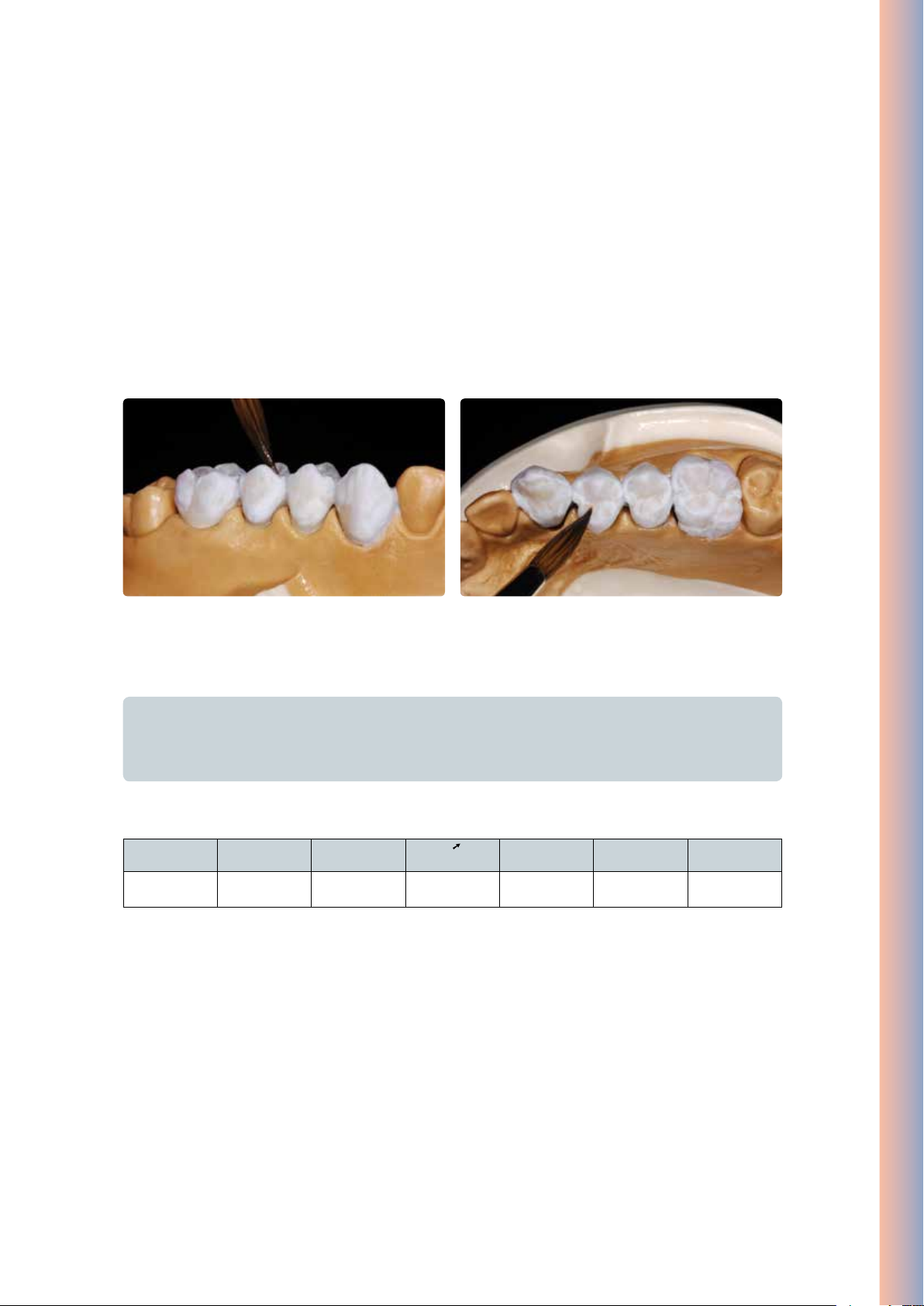
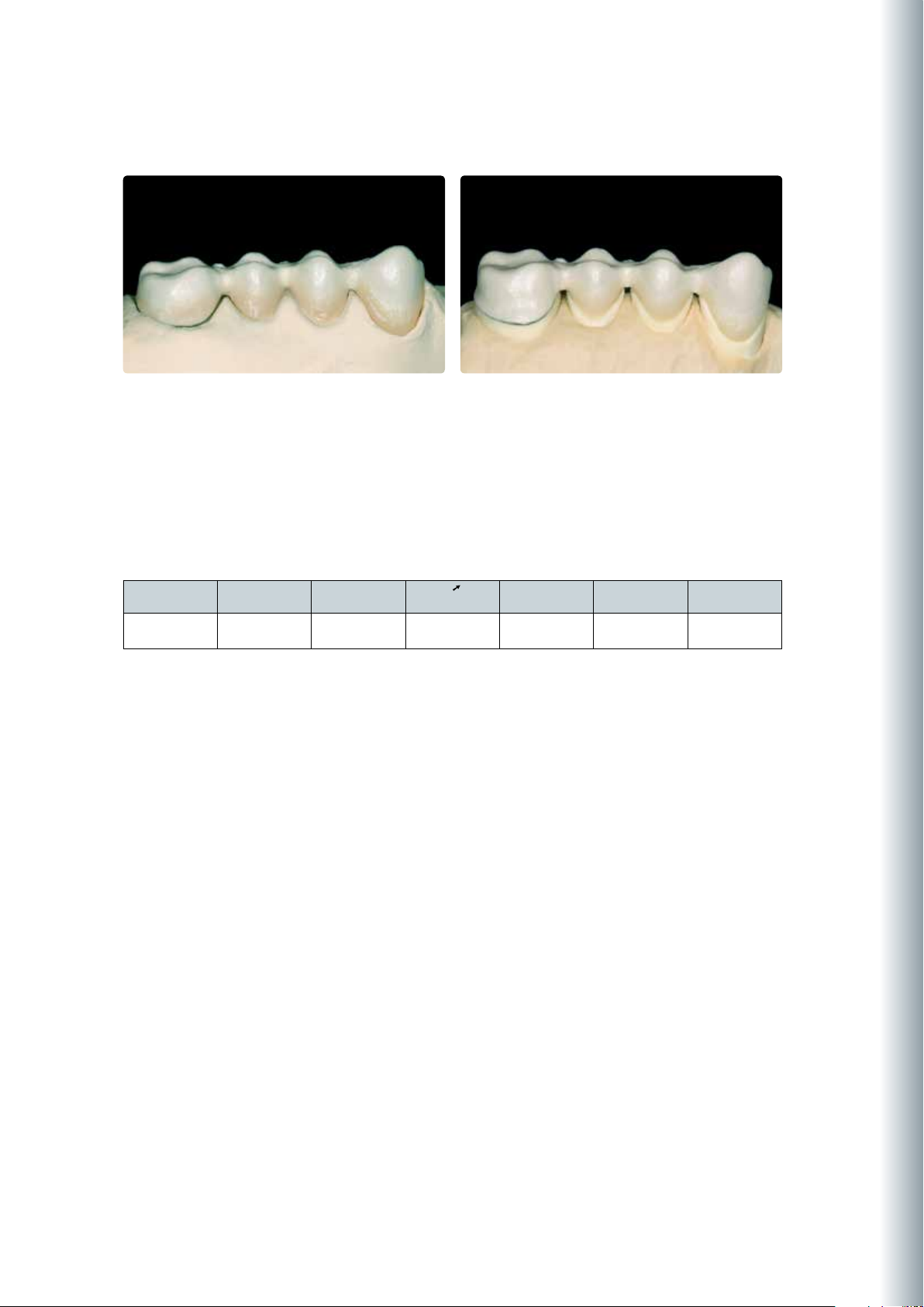
Finish and thoroughly clean the restoration. Clean under running water or with the steam jet. Blasting the restoration with
Al2O3 (type 50) at 1 bar (15 psi) pressure is only necessary if there is superficial contamination after cleaning. Thoroughly
dry the restoration and complete the missing areas. Pay special attention to interdental spaces as well as contact points.
Place the completely layered restoration on the firing tray and ensure adequate support. The firing tray with the restoration
should only be placed in the firing chamber once the furnace head is completely open and the beeper has sounded. Use
the firing parameters stipulated below to fire the restoration.
IPS InLine One – One-Layer Metal-Ceramic
Supplementing the restoration with Dentcisal material Final design of the occlusal surface
Important
• Usedistilledwatertorewetthemixedorevenalreadyappliedlayeringmaterial.
• Thefiringtraywiththerestorationshouldonlybeplacedinthefiringchamberandremovedfromitonce
the furnace head is completely open and the beeper has sounded.
Firing parameters 2nd Denticisal firing
T
°C/°F
B
°C /°F
S
min
t
°C/°F/min
H
min
V
°C/°F
1
V
2
°C/°F
900/1652 403/757 4 60/108 1 450/842 899/1650
23
Page 24
Individual finishing
Finishing and preparing for the Stains and Glaze firing
Before the Stains and Glaze firing, the restoration has to be prepared as follows:
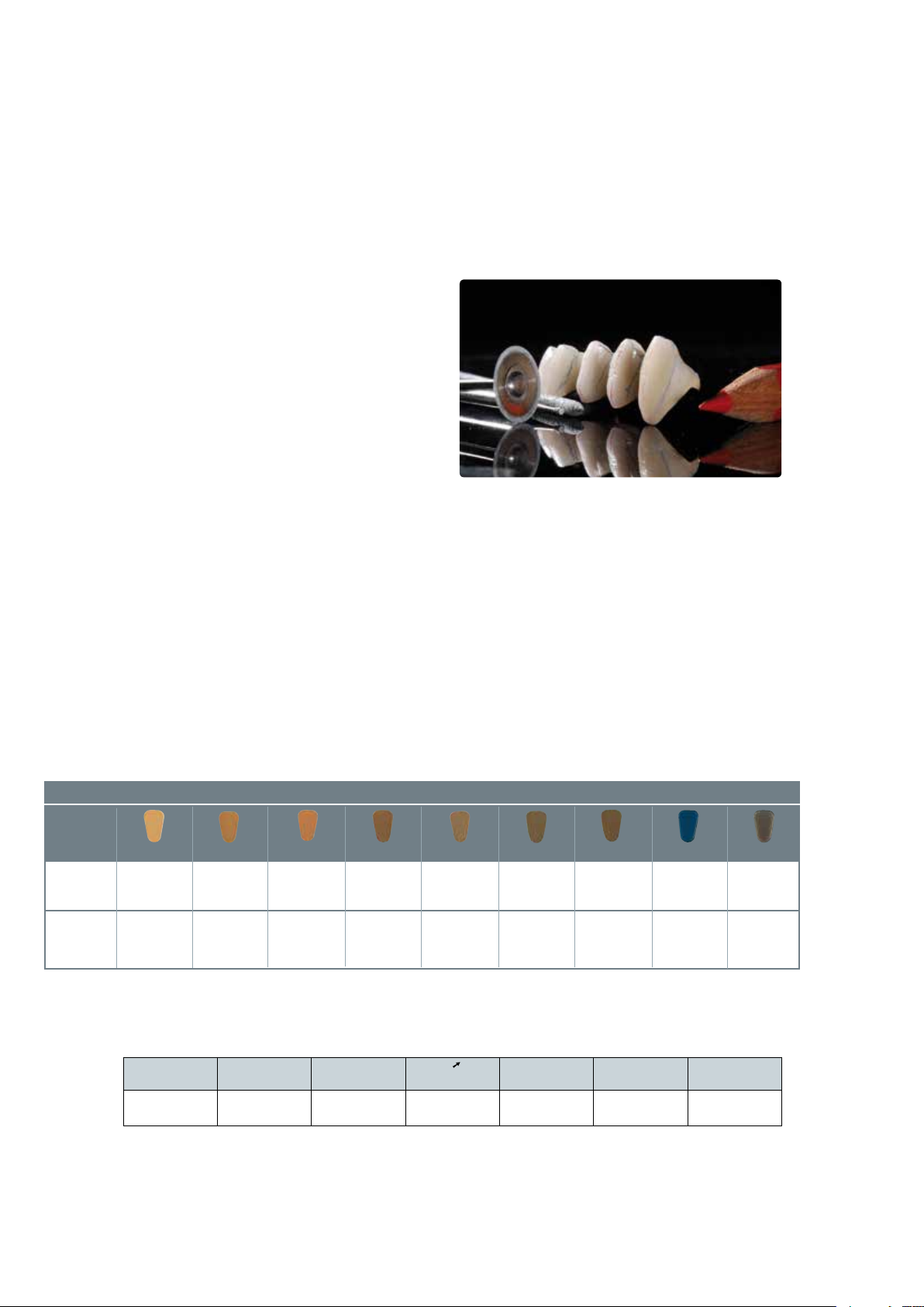
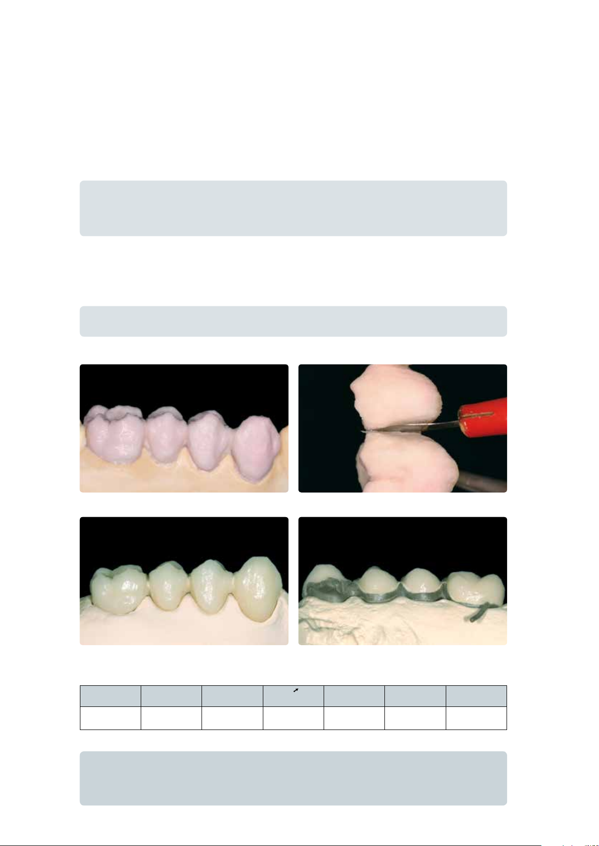
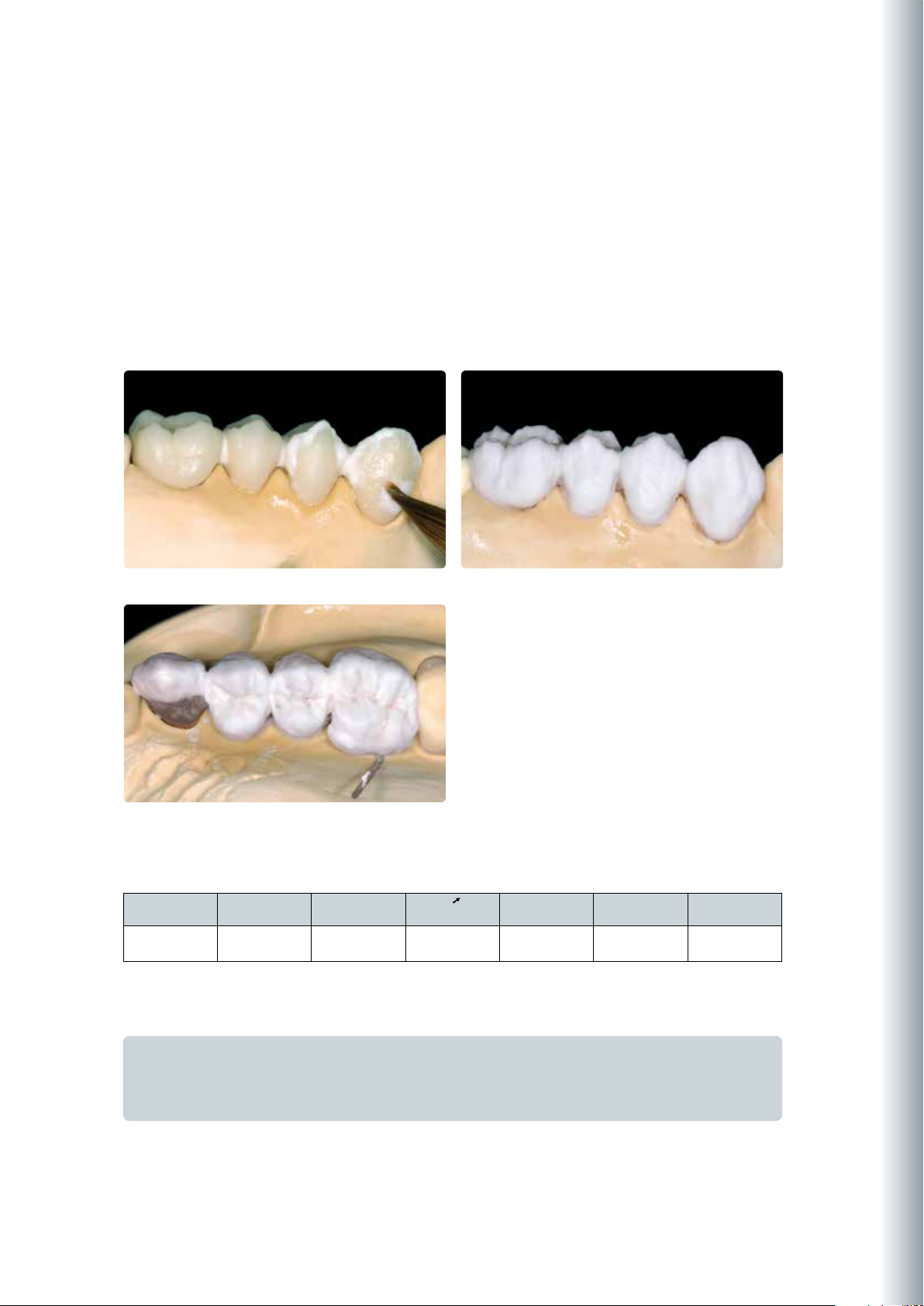
– Finish the restoration using diamond grinders and give it
a true-to-nature shape and surface structure, such as
growth lines and convex/concave areas.
– Areas which should exhibit a higher gloss after Glaze
firing (e.g. pontic rests) can be smoothed out and prepolished using silicone disks.
– If gold and/or silver dust was used to visualize the surface
texture, the restoration has to be thoroughly cleaned with
steam. Make sure to remove all gold or silver dust in
order to avoid any discolouration after firing.
The true-to-nature shape and surface texture are designed.
Stains and Characterization firing
Before the Stains and Characterization firing, the restoration must be free of dirt and grease. Any contamination after
cleaning must be prevented. The following steps must be observed:
– For better wetting of the stains, IPS InLine/IPS InLine PoM Glaze and Stains liquid may be slightly rubbed into the
surface.
– If a more intensive shade effect is desired, it is achieved by several staining procedures and repeated firing. The applica-
tion of too many stains results in an unnatural shade effect.
– The cusps and fissures can be individualized using Stains.
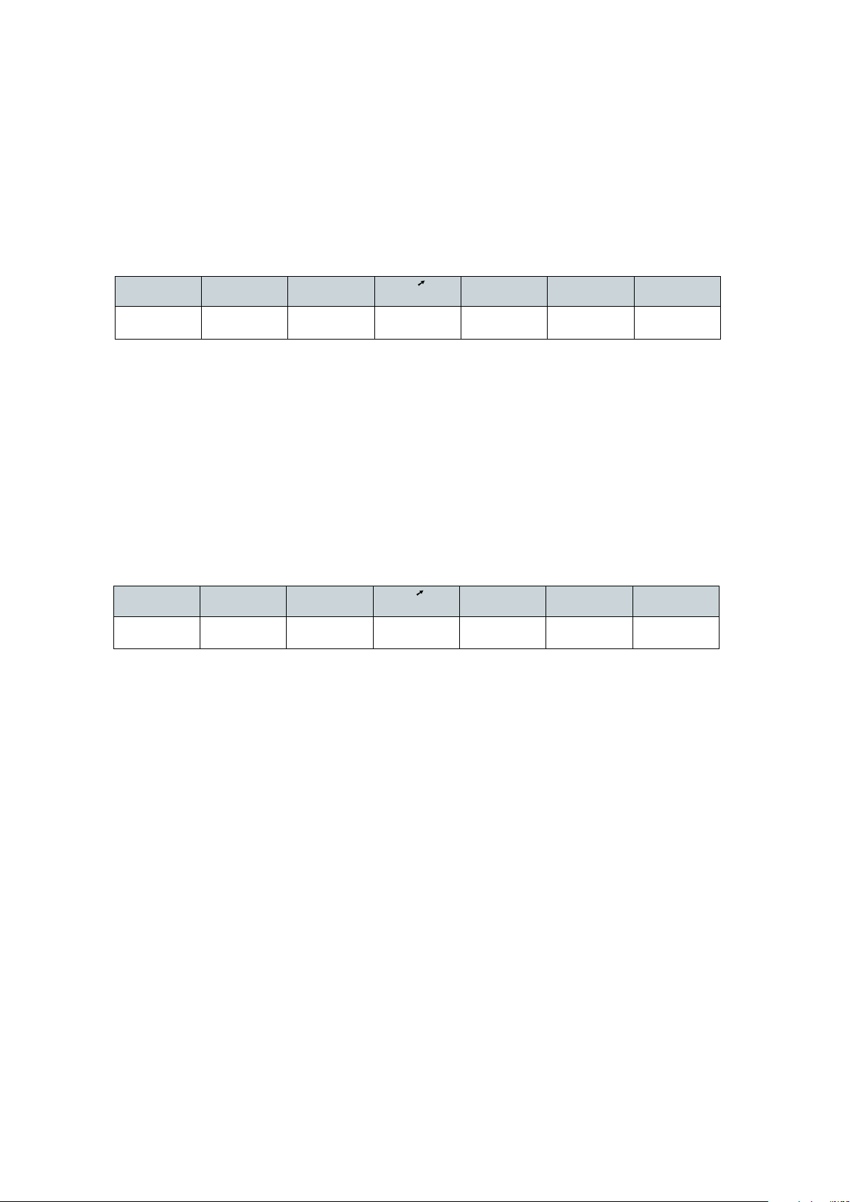
– The basic chromatic shade is supported with the corresponding Shade material (see table).
Shade
A-D
Chromascop
Shade combination table for IPS InLine One / IPS InLine / IPS InLine PoM
1
A1, B1, B2
110, 120, 130
BL1, BL2, BL3,
BL4
2
A2, A3, A3.5
140,
210, 220, 230,
240
3
B3, B4, D4
310, 320, 330
4
A4
340, 540
Firing parameters for the IPS InLine System Shade/Stains firing
T
°C/°F
B
°C/°F
S
min
850/1562 403/757 6 60/108 1 450/842 849/1560
5
C1, D2, D3
–
t
°C/°F/min
6
C2, C3, C4
410, 420,
430, 440,
510
H
min
7
–
520, 530
V
1
°C/°F
SI1
A1, A2, A3, B1,
B2, B3, B4
110–140, 210,
220, 310, 320,
BL1–BL4
SI2
A3.5, A4, C1,
C2, C3, C4, D2,
D3, D4
230, 240, 330,
340, 410–440,
510–540
V
2
°C/°F
24
Page 25
Shade adjustment with IPS InLine System Shade and Stains
These stains may be fired in a separate Stains firing. Minor shade adjustments and individual characterizations may also be
fired in the Glaze firing.
Dispense the desired quantity of IPS InLine System Shade and dilute and mix with IPS InLine System Glaze and Stains Liquid
to the desired consistency. Pooling should be avoided and the material must not be applied too thickly. If a more intensive
shade effect is desired, it is achieved by several staining procedures and repeated firing. The application of too many stains
results in an unnatural shade effect.
Firing parameters for the IPS InLine System Shade/Stains firing (Stains and Characterization firing)
T
°C/°F
850/1562 403/757 6 60/108 1 450/842 849/1560
Additional Stains and Characterization firing cycles can be conducted with the same firing parameters.
B
°C/°F
S
min
t
°C/°F/min
H
min
V
1
°C/°F
V
2
°C/°F
IPS InLine One – One-Layer Metal-Ceramic
Glaze firing
After the Stains and Characterization firing with IPS InLine System Shade/Stains, the Glaze firing is conducted.
– If required, homogenize the Glaze paste by stirring it before taking it from its jar. Extrude the desired amount of
IPS InLine System Glaze paste from the syringe or jar and mix thoroughly on the mixing pad. If a different consistency is
desired, adjust the consistency by diluting the material with IPS InLine System Glaze and Stains Liquid. Next, apply the
Glaze material in the usual manner using a brush. Make sure not to apply the Glaze material either in too thick or too
thin layers.
– Minor shade adjustments may be carried out together with the Glaze firing.
Firing parameters for the Glaze firing
T
°C/°F
850/1562 403/757 6 60/108 2 450/842 849/1560
When working with a furnace from other manufacturers these parameters have to be adjusted accordingly! Finally, the
shade of the completed restoration is checked.
If less gloss is desired, the holding time can be reduced to 1 minute.
If the gloss is unsatisfactory after the first Glaze firing, further Glaze firing procedures
may be conducted using the same firing parameters.
B
°C/°F
S
min
t
°C/°F/min
H
min
V
1
°C/°F
V
2
°C/°F
Add-On after Glaze firing
Mix the IPS InLine System Add-On 690 °C/1274 °F material with the desired build-up liquid, apply on the missing areas,
and fire.
Firing paramters for the Add-On 690°C/1274°F after Glaze firing
T
°C/°F
690/1274 403/757 4 60/108 1 450/842 689/1272
B
°C/°F
S
min
t
°C/°F/min
25
H
min
V
°C/°F
1
V
2
°C/°F
Page 26
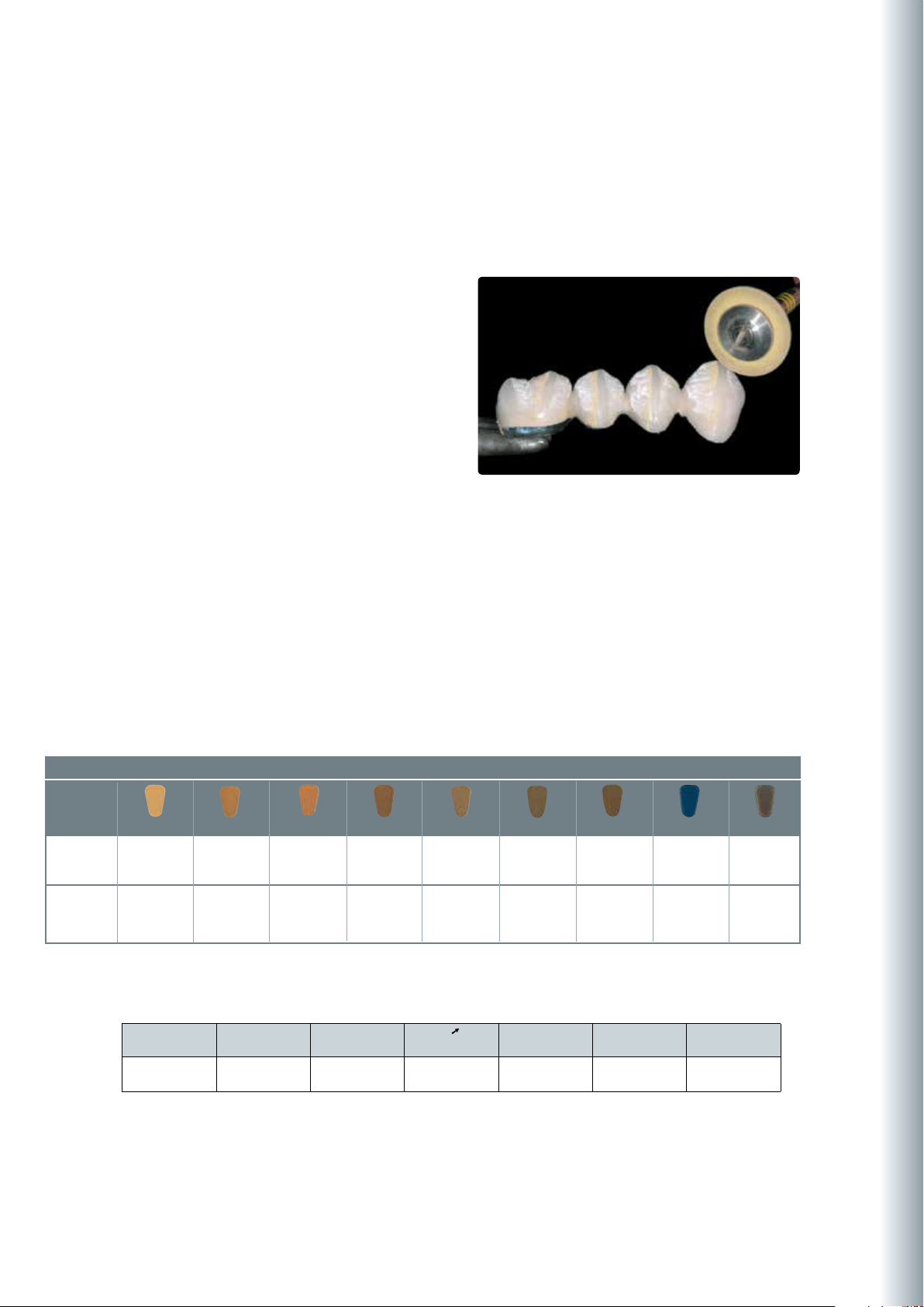
Individually designed and characterized bridge made of IPS InLine One
26
Page 27
®
InLine
IPS
– Conventionally Layered
Framework design criteria
The framework design is key to the success of durable metal-ceramic restorations. The more attention given to the framework
design, the better the final results and the clinical success will turn out to be.
1. Functional support of the veneering ceramic
The framework reflects the shape of the tooth in a reduced form. It should be designed in such a way that it supports the
cusps and incisal edges resulting in a virtually even layer thickness of the veneering ceramic in the cusp-fissure area. In this
way, the masticatory forces occurring during functional chewing are exerted on the framework rather than on the veneering
ceramic. Therefore, the framework must not show any angles and edges (see diagram) so that the masticatory forces do not
result in tension peaks, which may cause delamination and cracks. Any sharp angles or edges should be removed in the waxup rather than by grinding the metal framework. The wall thickness of the metal framework for single crowns must not be
less than 0.3 mm and for bridge abutments 0.5 mm after finishing (see diagram). For further information, please refer to the
Instructions for Use of the corresponding alloy.
IPS InLine – Conventionally Layered
Anterior crowns
Premolar crowns
correct
correct wrong
wrong
Molar crowns
correct wrong
27
Page 28

2. Framework design for fired ceramic shoulders
With fired ceramic shoulders, make sure that the framework rather than the veneer is supported by the prepared tooth.
The framework is thus reduced exactly to the inner edge of the chamfer or shoulder preparation to achieve functional
support of the framework on the preparation. Excellent accuracy of fit on the preparation is essential to ensure that the
shoulder material may not reach the inner aspects of the framework during subsequent application.
correct
wrong
3. Framework stability
The dimensions and shape of the interdental connector surfaces significantly influence the stability of the restoration
during processing, as well as the clinical long-term success after incorporation. Therefore, the dimensions of the interdental connector surface must be designed in accordance with the alloy used (take the 0.2% proof stress into account)!
The thermal behaviour of the selected alloy during processing has to be considered when designing the framework.
Single connector width
= single stability
Double the width of the
connector
= double the stability
28
Double the height of the
connector with single width
= eightfold stability
Page 29

4. Framework design for bridges
Thermal stress during firing and masticatory forces after cementation affect metal frameworks. These forces must be
transferred to the framework rather than the veneer. Particularly in the connector areas between bridge abutments and
bridge pontics in bridge reconstructions, the stability must be ensured with the help of the framework design and
adequate framework material thickness. The framework design and framework thickness must therefore meet all the
optical and functional requirements as well as the aspects of periodontal hygiene. A full wax-up with the corresponding
reduction of the ceramic provides the most predictable results.
During veneering with ceramic materials, the bridge framework is exposed to high temperatures several times. With an
inappropriate framework design or insufficient framework thickness, the high temperatures during firing may result in
distortion or inaccuracy of fit of the framework. A scallop-type design with e.g. interproximal reinforcements counteracts
this development. Additionally, this framework design (e.g. with cooling struts) ensures more even cooling of the
restoration during the cooling phase. This is particularly important if high gold alloys are used.
In order to enable optimum oral hygiene with bridge restorations, the design of the interdental spaces should be given
special attention. Adequate opening of the interdental area without creating black triangles should be given special
attention when designing the bridge in order to ensure proper periodontal hygiene with interdental brushes and dental
floss.
IPS InLine – Conventionally Layered
correct
correct
wrong
29
Page 30

5. Design of bridge pontics
Bridge pontics are designed with esthetic and functional aspects as well as oral hygiene in mind. The area of the pontic
that contacts the alveolar ridge should be made of ceramic.
In order to ensure adequate stability between the bridge pontic and the bridge abutments, a palatal and/or lingual scallop
is recommended. Furthermore, to ensure even cooling of the bridge pontic that absorbs the most heat, additional
cooling struts are advantageous.
Bridge pontic design – ovate pontic Bridge pontic design – saddle-type pontic
6. Interface between metal and ceramic
The interface between the metal framework and the veneering ceramic must be clearly defined. If possible, incorporate a
right angle finish line. The junctures between the metal framework and the veneering ceramic must not be located in the
contact area nor on surfaces involved in masticatory functions. The interface in the interdental area should be designed in
such a way that cleaning of these hard-to-reach areas is possible.
correct
correct
wrong
wrong
30
Page 31

Holding pins
FRAMEWORK DESIGN
for
met a l
-
cer a mi c
res t or a ti o n s
Manual
In order not to damage the crown wall during
processing, the crown and bridge frameworks are
provided with holding pins. They are directly
attached to the framework with the help of wax.
Dimensions of Ø 0.5–1.0 mm for the holding pins
have proven to be useful. They can be used to
secure the framework by means of holding clips.
Furthermore, the holding pins also act as cooling
struts during casting and firing.
IPS InLine – Conventionally Layered
Important
The holding pins must be placed in such a way that they do not interfere during try-in or in the articulator.
They should only be removed without causing overheating once the restoration has been completed.
Please refer to the “Framework Design Guidelines for Metal-Ceramic Restorations” for additional
information on framework design. They can be ordered from your Ivoclar Vivadent contact
address.
31
Page 32

Step-by-step procedure
Starting situation
Maxillary and mandibular model articulated in the “Stratos 200” Starting situation for metal-supported IPS InLine restorations
Framework design
Design the framework with a reduced anatomical shape taking the planned layering into account. The wall thickness for
single crowns should be at least 0.3 mm and at least 0.5 mm for abutment crowns.
Make sure to provide sufficient stability of shape for the framework. Avoid sharp transitions and edges. Design the
connector areas between the individual units in such a stable way that they meet the requirements of interdental hygiene
and the alloy used.
Design the framework in a reduced supported shape.
32
Page 33

Alloy processing / oxide firing
The cast metal framework is finished using tungsten carbide burs or ceramic-bonded grinding instruments. To make
room for the ceramic shoulder (labial or circular), the marginal area of the framework is reduced up to the inner edge of
the chamfer or shoulder preparation.
IPS InLine – Conventionally Layered
Surface finishing before blasting.
After blasting, clean the metal framework with a steam jet and allow to dry thoroughly.
Conduct the oxide firing according to the instructions of the manufacturer.
Carefully blast the framework with aluminium oxide Al2O3 50–100 µm (observe the instruc-
After oxide firing, the framework should exhibit an evenly oxidized surface.
tions of the alloy manufacturer).
33
Page 34
IPS InLine layering diagram
Incisal
Opaquer
Dentin
Deep Dentin
Metal framework thickness:
– Crowns min. 0.3 mm
– Bridge abutments min. 0.5 mm
Ideal layer
thickness
Framework
Opaquer
Deep Dentin
cervical
incisal
Dentin
cervical
incisal
Incisal
cervical
incisal
These figures are drawn from past experience and they may vary in certain situations.
0.3–0.5 mm
0.1 mm
–
–
1 mm
0.7 mm
0.2 mm
0.5 mm
Limited layer
thickness
0.3–0.5 mm
0.1 mm
0.3 mm
0.1 mm
0.5 mm
0.3 mm
0.1 mm
0.4 mm
Depending on the clinical situation or the selected
shade system (Chromascop, A-D and Bleach),
various components may be used to achieve
targeted shade effects.
The Incisal materials in A-D shades are applied up
to the centre of the cervical third.
With Chromascop shades, the Incisal materials are
only layered up to the beginning of the cervical
third.
e.g. Chromascop shadese.g. A–D shades
34
Page 35
Opaquer Firing
Paste opaquer
st
1
Opaquer firing (wash firing) (paste opaquer)
Select the IPS InLine System Opaquer paste in the corresponding tooth shade. If required, homogenize the opaquer paste
by stirring it before taking it from its jar. Extrude the desired amount from the syringe or jar and mix thoroughly on the
mixing pad. Thin it, if required. Apply the first opaquer layer thinly and agitate it into the alloy surface. After firing and
cooling, clean the opaquerized metal framework with the steam jet and dry with oil-free air.
IPS InLine – Conventionally Layered
Tip:
The consistency of the paste opaquer can be individually adjusted using the IPS InLIne System Opaquer Liquid.
2nd Opaquer firing (paste opaquer)
Apply the second opaquer layer in such a way that the metal framework is entirely covered with opaquer. After firing, the
IPS InLine System Opaquer should show a covering, silky-mat shiny surface. After the opaquer firing, the conditioned
surfaces of the alloy framework should be entirely covered with opaquer.
Important
The firing tray with the opaquerized metal framework should only be placed in the firing chamber and
removed from it once the furnace head is completely open and the beeper has sounded.
Firing parameters IPS InLine System Opaquer (paste opaquer), 1
T
°C/°F
930/1706 403/ 757 6 100/180 2 450/842 929/1704
B
°C /°F
S
min
t
°C/°F/min
st
and 2nd Opaquer firing
H
min
35
V
1
°C/°F
V
°C/°F
2
Page 36

IPS InLine System Opaquer F
The Opaquer F can be used to reinforce the in-depth
fluorescence.
– Either: Apply the Opaquer F as a thin, third opaquer
layer and fire (930 °C/1706 °F).
– Or: Mix up to 20% of Opaquer F with the conventional
IPS InLine System Opaquer before the second layer is
applied and fire at 930 °C/1706 °F.
Powder opaquer
1st Opaquer firing (wash firing) (powder opaquer)
Select the IPS InLine System Powder Opaquer in the corresponding tooth shade. Remove the amount of powder opaquer
required for the wash from the jar and mix it thoroughly with the Powder Opaquer Liquid on the mixing pad until it has
reached the desired consistency. Apply the first opaquer layer thinly on the metal framework and agitate it into the alloy
surface. After firing and cooling, clean the opaquerized metal framework with the steam jet and dry with oil-free air.
Important
Mix IPS InLine System Powder Opaquer only with the Powder Opaquer Liquid.
36
Page 37
2nd Opaquer firing (powder opaquer)
Remove the amount of powder opaquer required for the covering layer from the jar and mix it together with the
remaining, dried up “wash opaquer” on the mixing pad. Then, mix the powder opaquer with the Powder Opaquer Liquid
until it has reached the desired consistency.
Apply the second opaquer layer evenly and in such a way that the metal framework is entirely covered with opaquer. After
firing according to the stipulated firing parameters, the IPS InLine System Powder Opaquer should show a covering, silkymat shiny surface. After the opaquer firing, the conditioned surfaces of the alloy framework should be entirely covered
with opaquer.
IPS InLine – Conventionally Layered
Tip:
A glass or ceramic instrument is optimally suitable to apply the IPS InLine Powder Opaquer for the opaquer firing.
Naturally, a brush can also be used to apply IPS InLine Powder Opaquer.
The IPS InLine System Powder Opaquer and Powder
Opaquer Liquid are ideally suitable for the application
with conventional spray-on techniques. Mix the powder
opaquer to a thin consistency, depending on the sprayon system used. Observe the instructions of the
manufacturer of the spray-on systems.
Important
• Usedistilledwatertorewetthemixedorthealreadyappliedpowderopaquer.
• Thefiringtraywiththeopaquerizedmetalframeworkshouldonlybeplacedinthefiringchamberand
removed from it once the furnace head is completely open and the beeper has sounded.
Firing parameters IPS InLine System Opaquer (powder opaquer), 1
T
°C/°F
B
°C/°F
S
min
t
°C/°F/min
st
and 2nd Opaquer firing
H
min
°C/°F
V
1
V
2
°C/°F
960/1760 403/757 4 100/180 2 450/842 959/1758
Important
IPS InLine System Powder Opaquer
– Alloys (CTE of approx. 13.8 to 15.0 x 10⁻⁶/K at 25-500 °C) with a solidus point of ≥ 1080 °C are suitable for
opaquerizing with the powder opaquer at a firing temperature of 960 °C.
37
Page 38

1st and 2nd Margin firing
A ceramic shoulder can be fabricated on the metal framework after the opaquer firing, if the necessary space has been
provided during finishing. Before creating the ceramic shoulder, seal the stone die with IPS Margin Sealer and then, after
drying, with IPS Ceramic Separating Liquid.
correct
After that, the IPS Margin material in the respective shade is generously applied in drop-shaped increments in the cervical
area (i.e. the outer surface of the ceramic is given a convex design) and dried. Then, carefully remove the framework with
the dried shoulder material from the die.
Tip:
When designing a ceramic shoulder (particularly for bridges), the Margin material may be applied slightly higher up in
the proximal areas. This will reduce the interdental shrinkage during the subsequent Dentin and Incisal firings.
wrong
38
Page 39
After firing, the shoulder may have to be slightly adjusted by grinding in order to remove any interfering areas.
Subsequently, the accuracy of fit (sinter shrinkage) has to be optimized by means of a 2nd Margin firing. Use the same
Margin materials as for the 1st Margin firing for that purpose.
First, however, isolate the die again using IPS Ceramic Separating Liquid. Subsequently, supplement the missing areas by
carefully inserting the shoulder material into the gap created during the 1st Margin firing so that the ceramic shoulder is
provided with optimum accuracy of fit. Complete the shoulder, dry, and carefully remove the framework with the completed
and dried shoulder material from the die and place it on the firing tray.
IPS InLine – Conventionally Layered
Firing parameters for IPS InLine Margin (1st and 2nd firing)
T
°C/°F
B
°C /°F
S
min
t
°C/°F/min
H
min
V
°C/°F
1
930/1706 403/757 4 60/108 1 450/842 929/1704
V
°C/°F
2
39
Page 40
1st Dentin and Incisal firing
Isolate the model before layering the Dentin and Incisal materials. In this way, the ceramic material is prevented from drying out or sticking to the model respectively. Isolate the stone die and the adjacent areas using IPS Model Sealer.
Additionally, separate the area of the pontics with IPS Ceramic Separating Liquid.
Tip:
To achieve an optimum bond between the ceramic material and the opaquer surface, apply a small amount of
IPS InLine Deep Dentin or Dentin material to the cervical and interdental areas (for bridges) and slightly roughen it.
In this way, the adaption of the ceramic material on the opaquer surface is enhanced.
Make sure that the restoration is slightly overcontoured so that the actual tooth shape is achieved after firing. The bridge
is lifted off the model to supplement the contact points with Dentin and Incisal materials. Before firing, separate the entire
interdental area down to the opaquer.
Tip:
Densify the ceramic surface (after contouring) with a large, dry brush toward the cervical margin before firing.
The ceramic material is applied according to the layering diagram.
Restoration after the 1
For an optimum firing result, the interdental areas must be separated down to the opaquer.
st
Dentin / Incisal firing
Firing parameters for the 1st Dentin and Incisal firing
T
°C
B
°C
S
min
t
°C/min
H
min
V
°C
1
V
°C
910/1670 403/757 4 60/108 1 450/842 909/1668
Important
• Usedistilledwatertorewetthemixedorevenalreadyappliedlayeringmaterial.
• Thefiringtraywiththerestorationshouldonlybeplacedinthefiringchamberandremovedfromitonce
the furnace head is completely open and the beeper has sounded.
2
40
Page 41
2nd Dentin and Incisal firing
Finish and thoroughly clean the restoration. Clean under running water or with the steam jet. Blasting the restoration with
Al2O3 (type 50) at 1 bar (15 psi) pressure is only necessary if there is superficial contamination after cleaning. Thoroughly
dry the restoration and complete the missing areas. Pay special attention to interdental spaces as well as contact points.
Place the completely layered restoration on the firing tray and ensure adequate support. The firing tray with the restoration
should only be placed in the firing chamber once the furnace head is completely open and the beeper has sounded. Use the
firing parameters stipulated below to fire the restoration.
IPS InLine – Conventionally Layered
Supplementing the restoration with Dentin and Incisal materials
Final design of the occlusal surface
Firing parameters for the 2nd Dentin and Incisal firing
T
°C
B
°C
S
min
t
°C/min
H
min
V
°C
1
900/1652 403/757 4 60/108 1 450/842 899/1650
V
°C
2
Important
• Usedistilledwatertorewetthemixedorevenalreadyappliedlayeringmaterial.
• Thefiringtraywiththerestorationshouldonlybeplacedinthefiringchamberandremovedfromitonce
the furnace head is completely open and the beeper has sounded.
41
Page 42
Margin Add-On firing
Margin Add-On is an add-on material for the ceramic shoulder area, which is applied after the main or add-on firing cycles
with Dentin and Incisal materials. Thus, it is possible to adjust the accuracy of the marginal shoulder. Subsequently, the
restoration is completed with the new Shade/Stains and Glaze materials.
Firing parameters for the Margin Add-On firing
T
°C/°F
B
°C/°F
min
S
t
°C/°F/min
H
min
V
°C/°F
1
V
2
°C/°F
900/1652 403/757 4 60/108 1 450/842 899/ 1650
Add-On firing
Before the completion of a restoration, small adjustments, such as contact points, pontic rests, or accuracy of fit of the
shoulder, may be necessary.
In order to employ a lower firing temperature, IPS InLine Dentin/Incisal materials can be mixed with IPSInLine Add-On in a
1:1 ratio and subsequently applied.
Firing parameters for the Margin Add-On firing
T
°C/°F
B
°C/°F
S
min
t
°C/°F/min
H
min
V
1
°C/°F
V
°C/°F
2
860/1580 403/757 4 60/108 1 450/842 859/1578
42
Page 43
Individual finishing
Finishing and preparing for the Stains and Glaze firing
Before the Stains and Glaze firing, the restoration has to be prepared as follows:
– Finish the restoration using diamond grinders and give it a
true-to-nature shape and surface structure, such as growth
lines and convex/concave areas.
– Areas which should exhibit a higher gloss after Glaze firing
(e.g. pontic
rests) can be smoothed out and prepolished using silicone
disks.
– If gold and/or silver dust was used to visualize the surface
texture, the restoration has to be thoroughly cleaned with
steam. Make sure to remove all gold or silver dust in order to
avoid any discolouration after firing.
IPS InLine – Conventionally Layered
The true-to-nature shape and surface texture are designed.
Shade
A-D
Chromascop
Stains and Characterization firing
Before the Stains and Characterization firing, the restoration must be free of dirt and grease. Any contamination after
cleaning must be prevented. The following steps must be observed:
– For better wetting of the stains, IPS InLine System Glaze and Stains liquid may be slightly agitated on the surface.
– If a more intensive shade effect is desired, it is achieved by several staining procedures and repeated firing. The applica-
tion of too many stains results in an unnatural shade effect.
– The cusps and fissures can be individualized using Stains.
– The basic chromatic shade is supported with the corresponding Shade material (see table).
Shade combination table for IPS InLine One / IPS InLine / IPS InLine PoM
1
A1, B1, B2
110, 120, 130
BL1, BL2, BL3,
BL4
2
A2, A3, A3.5
140,
210, 220, 230,
240
3
B3, B4, D4
310, 320, 330
4
A4
340, 540
5
C1, D2, D3
–
6
C2, C3, C4
410, 420,
430, 440,
510
7
–
520, 530
SI1
A1, A2, A3, B1,
B2, B3, B4
110–140, 210,
220, 310, 320,
BL1–BL4
SI2
A3.5, A4, C1,
C2, C3, C4, D2,
D3, D4
230, 240, 330,
340, 410–440,
510–540
Firing parameters for the IPS InLine System Shade/Stains firing
T
°C/°F
B
°C/°F
S
min
t
°C/°F/min
H
min
V
1
°C /°F
850/1562 403/757 6 60/108 1 450/842 849/1560
43
V
2
°C/°F
Page 44

Shade adjustment with IPS InLine System Shade and Stains
These stains may be fired in a separate Stains firing. Minor shade adjustments and individual characterizations may also be
fired in the Glaze firing.
Dispense the desired quantity of IPS InLine System Shade and dilute and mix with IPS InLine System Glaze and Stains Liquid
to the desired consistency. Pooling should be avoided and the material must not be applied too thickly. If a more intensive
shade effect is desired, it is achieved by several staining procedures and repeated firing. The application of too many stains
results in an unnatural shade effect.
Firing parameters for the IPS InLine System Shade/Stains firing (Stains and Characterization firing)
T
°C/°F
B
°C/°F
min
S
t
°C/°F/min
H
min
V
1
°C/°F
V
2
°C /°F
850/1562 403/757 6 60/108 1 450/842 849/1560
Additional Stains and Characterization firing cycles can be conducted with the same firing parameters.
Glaze firing
After the Stains and Characterization firing with IPS InLine System Shade/Stains, the Glaze firing is conducted.
– Remove IPS InLine System Glaze paste from the syringe and mix thoroughly. If a different consistency is desired, adjust
the consistency by diluting the material with IPS InLine System Glaze and Stains Liquid. Next, apply the Glaze material in
the usual manner using a brush. Make sure not to apply the Glaze material either in too thick or too thin layers.
– Minor shade adjustments may be carried out together with the Glaze firing.
Firing parameters for the Glaze firing
T
°C/°F
B
°C/°F
S
min
t
°C/°F/min
H
min
V
°C/°F
1
V
2
°C/°F
850/1562 403/757 6 60/108 2 450/842 849/1560
When working with a furnace from another manufacturer, these parameters have to be adjusted accordingly! Finally, the
shade of the completed restoration is checked.
If less gloss is desired, the holding time can be reduced to 1 minute.
If the gloss is unsatisfactory after the first Glaze firing, further Glaze firing procedures
may be conducted using the same firing parameters.
44
Page 45

Add-On after Glaze Firing
Mix the IPS InLine System Add-On 690 °C/1274 °F material with the desired build-up liquid, apply on the missing areas,
and fire.
Firing parameters for IPS InLine System Add-On 690°C/1274°F after Glaze firing
T
°C/°F
690/1274 403/757 6 60/108 1 450/842 689/1272
B
°C/°F
min
S
t
°C/°F/min
H
min
V
1
°C/°F
V
2
°C/°F
IPS InLine – Conventionally Layered
Individually designed and characterized bridge made of IPS InLine
45
Page 46

InLine® PoM
IPS
– Accurate Press-On Technique
Framework design criteria
The framework design is key to the success of durable metal-ceramic restorations. The more attention given to the framework
design, the better the final results and the clinical success will turn out to be.
1. Functional support of the veneering ceramic
The framework reflects the shape of the tooth in a reduced form. It should be designed in such a way that it supports the
cusps and incisal edges resulting in a virtually even layer thickness of the veneering ceramic in the cusp-fissure area. In this
way, the masticatory forces occurring during functional chewing are exerted on the framework rather than on the veneering
ceramic. Therefore, the framework must not show any angles and edges (see diagram) so that the masticatory forces do not
result in tension peaks, which may cause delamination and cracks. Any sharp angles or edges should be removed in the waxup rather than by grinding the metal framework. The wall thickness of the metal framework for single crowns must not be
less than 0.3 mm and for bridge abutments 0.5 mm after finishing (see diagram). For further information, please refer to the
Instructions for Use of the corresponding alloy.
Anterior crowns
Premolar crowns
correct
correct wrong
wrong
Molar crowns
correct wrong
46
Page 47
2. Framework design for pressed-on ceramic shoulders
With pressed-on ceramic shoulders, make sure that the framework rather than the veneer is supported by the prepared
tooth. The framework is thus reduced exactly to the inner edge of the chamfer or shoulder preparation to achieve
functional support of the framework on the preparation. Excellent accuracy of fit on the preparation is essential to ensure
that the shoulder material may not reach the inner aspects of the framework during subsequent application.
IPS InLine PoM – Accurate Press-On Technique
correct
wrong
3. Framework stability
The dimensions and shape of the interdental connector surfaces significantly influence the stability of the restoration
during processing as well as the clinical long-term success after incorporation. Therefore, the dimensions of the interdental
connector surface must be designed in accordance with the alloy used (take the 0.2% proof stress into account)! The
thermal behaviour of the selected alloy during processing has to be considered when designing the framework.
Single connector width
= single stability
Double the width of the
connector
= double the stability
47
Double the height of the
connector with single width
= eightfold stability
Page 48
4. Framework design for bridges
Thermal stress during firing and masticatory forces after cementation affect metal frameworks. These forces must be
transferred the framework rather than the veneer. Particularly in the connector areas between bridge abutments and
bridge pontics in bridge reconstructions, the stability must be ensured with the help of the framework design and
adequate framework material thickness. The framework design and framework thickness must therefore meet all the
optical and functional requirements as well as the aspects of periodontal hygiene. A full wax-up with the corresponding
reduction of the ceramic provides the most predictable results.
During veneering with ceramic materials, the bridge framework is exposed to high temperatures several times. With an
inappropriate framework design or insufficient framework thickness, the high temperatures during firing may result in
distortion or inaccuracy of fit of the framework. A scallop-type design with e.g. interproximal reinforcements counteracts
this development. Additionally, this framework design (e.g. with cooling struts) ensures more even cooling of the restoration during the cooling phase. This is particularly important if high gold alloys are used.
In order to enable optimum oral hygiene with bridge restorations, the design of the interdental spaces should be given
special attention. Adequate opening of the interdental area without creating black triangles should be given special
attention when designing the framework in order to ensure proper periodontal hygiene with interdental brushes and
dental floss.
correct
correct
wrong
48
Page 49

5. Design of bridge pontics
Bridge pontics are designed with esthetic and functional aspects as well as oral hygiene in mind. The area of the pontic
that contacts the alveolar ridge should be made of ceramic.
In order to ensure adequate stability between the bridge pontic and the bridge abutments, a palatal and/or lingual scallop
is recommended. Furthermore, to ensure even cooling of the bridge pontic that absorbs the most heat, additional
cooling struts are advantageous.
Bridge pontic design – ovate pontic Bridge pontic design – saddle-type pontic
IPS InLine PoM – Accurate Press-On Technique
6. Interface between metal and ceramic
The interface between the metal framework and the veneering ceramic must be clearly defined. If possible, incorporate a
right angle finish line. The junctures between the metal framework and the veneering ceramic must neither be located in
the contact area nor on surfaces involved in masticatory functions. The interface in the interdental area should be
designed in such a way that cleaning of these hard-to-reach areas is possible.
correct
correct
wrong
wrong
49
Page 50

Retention pins
FRAMEWORK DESIGN
for
met a l
-
cer a mi c
res t or a ti o n s
Manual
It is important for the press-on-metal technique that retention pins are attached to the crown and bridge frameworks.
These retention pins have to be attached in the area of the pontics or the scallops. They are directly attached to the framework with the help of wax. Dimensions of Ø 1.0–1.5 mm for the retention pins have proven to be useful.
Advantages of cast-on retention pins:
1. Act as cooling struts during casting and firing
2. Retention for improved fixation in the investment material during the press-on procedure with IPS InLine PoM
3. Handling aid for further processing
The retention pins have to be shaped in such a way that the bridge framework cannot distort and/or move in the
investment material. At least 2 retention pins (diverging) have to be provided for bridge frameworks, one of which has to
be positioned in the area of the pontic.
If straight wax wires are used, 2 diverging wires have to be applied for bridges. A profile has to be positioned in the area of the pontic.
Pontics may also given a hollow design (e.g.
Inzoma) for enhanced heat distribution and/or
cooling.
Important
The retention pins must be placed in such a way that they do not interfere during try-in or in the articulator.
They should only be removed without causing overheating once the restoration has been completed.
Please refer to the “Framework Design Guidelines for Metal-Ceramic Restorations” for additional
information on framework design. They can be ordered from your Ivoclar Vivadent contact
address.
50
Page 51

Step-by-step procedure
Starting situation
Maxillary and mandibular model articulated in the “Stratos 200” Starting situation for the metal-supported IPS InLine PoM restoration
IPS InLine PoM – Accurate Press-On Technique
Framework design
Design the framework with a reduced anatomical shape taking the planned press-on procedure into account. The wall
thickness for single crowns should be at least 0.3 mm and at least 0.5 mm for abutment crowns. Make sure to provide
sufficient stability of shape for the framework. Avoid sharp transitions and edges. Design the connector areas between the
individual units in such a stable way that they meet the requirements of interdental hygiene and the alloy used.
Design the framework in a reduced supported shape.
– Due to the optical properties, the ceramic should feature a thickness of at least 0.8 mm in connection with
the press-on-metal technique.
– Especially if frameworks are to be pressed over, it is recommended to attach retention grooves in the
palatal / lingual area.
51
Page 52

Alloy processing / oxide firing
The cast metal framework is finished using tungsten carbide burs or ceramic-bonded grinding instruments. To make room
for the ceramic shoulder (labial or circular), the marginal area of the framework is reduced up to the inner edge of the
chamfer or shoulder preparation.
Surface finishing before blasting Carefully blast the framework with aluminium oxide Al2O3 50–100 µm
After blasting, clean the metal framework with a steam jet and allow to dry thoroughly.
Conduct the oxide firing according to the instructions of the manufacturer.
After oxide firing, the framework should exhibit an evenly oxidized surface.
(observe the instructions of the alloy manufacturer).
52
Page 53

IPS InLine PoM layering diagram
Dieter Grübel
®
InLine PoM
IPS
Edition
LIEBE ZUM DETAIL –ÄSTHETIK UND MORPHOLOGIE
Press-on-Metal-Keramik
Opaquer
IPS InLine PoM – Accurate Press-On Technique
PoM
Opalescence effect
Shade Incisal 1
Shade=Hue A1 etc.
Shade 1
Metal framework thickness:
– Crowns min. 0.3 mm
– Bridge abutments min. 0.5 mm
Chroma
Stains orange
Ideal layer
thickness
Framework
Opaquer
PoM
These figures are drawn from past experience and they may vary in certain situations.
Halo effect
Stains vanilla
Mamelon effect
Stains vanilla,
Shade Incisal 1
Brightness value
Stains white
0.3–0.5 mm
0.1 mm
0.8–1.5 mm
Depending on the desired
individualization, IPS InLine System
Shade/Stains can be used to
achieve true-to-nature shade
Limited layer
thickness
0.3–0.5 mm
0.1 mm
0.8
effects.
Chroma
Stains red
Shade Stains
You can find additional information on esthetic individualization in the edition “Love for
Detail” by D. Grübel. It can be ordered from your Ivoclar Vivadent contact address.
53
Page 54

Opaquer Firing
Paste opaquer
st
1
Opaquer firing (wash firing) (paste opaquer)
Select the IPS InLine System Opaquer paste in the corresponding tooth shade. If required, homogenize the opaquer paste
by stirring it before taking it from its jar. Extrude the desired amount from the syringe or jar and mix thoroughly on the
mixing pad. Thin it, if required. Apply the first opaquer layer thinly and agitate it into the alloy surface. After firing and
cooling, clean the opaquerized metal framework with the steam jet and dry with oil-free air.
Tip:
The consistency of the paste opaquer can be individually adjusted using the IPS InLIne System Opaquer Liquid.
2nd Opaquer firing (paste opaquer)
Apply the second opaquer layer in such a way that the metal framework is entirely covered with opaquer. After firing, the
IPS InLine System Opaquer should show a covering, silky-mat shiny surface. After the opaquer firing, the conditioned
surfaces of the alloy framework should be entirely covered with opaquer.
Important
The firing tray with the opaquerized metal framework should only be placed in the firing chamber and
removed from it once the furnace head is completely open and the beeper has sounded.
Firing parameters IPS InLine System Opaquer (paste opaquer), 1
T
°C/°F
B
°C /°F
S
min
t
°C/°F/min
st
and 2nd Opaquer firing
H
min
V
1
°C/°F
V
°C/°F
2
930/1706 403/ 757 6 100/180 2 450/842 929/1704
54
Page 55

IPS InLine System Opaquer F
The Opaquer F can be used to reinforce the in-depth
fluorescence.
– Either: Apply the Opaquer F as a thin, third opaquer
layer and fire (930 °C/1706 °F).
– Or: Mix up to 20% of Opaquer F with the conventional
IPS InLine System Opaquer before the second layer is
applied and fire at 930 °C/1706 °F.
IPS InLine PoM – Accurate Press-On Technique
Powder opaquer
1st Opaquer firing (wash firing) (powder opaquer)
Select the IPS InLine System Powder Opaquer in the corresponding tooth shade. Remove the amount of powder opaquer
required for the wash from the jar and mix it thoroughly with the Powder Opaquer Liquid on the mixing pad until it has
reached the desired consistency. Apply the first opaquer layer thinly on the metal framework and agitate it into the alloy
surface. After firing and cooling, clean the opaquerized metal framework with the steam jet and dry with oil-free air.
Important
Mix IPS InLine System Powder Opaquer only with the Powder Opaquer Liquid.
55
Page 56

2nd Opaquer firing (powder opaquer)
Remove the amount of powder opaquer required for the covering layer from the jar and mix it together with the
remaining, dried up “wash opaquer” on the mixing pad. Then, mix the powder opaquer with the Powder Opaquer Liquid
until it has reached the desired consistency.
Apply the second opaquer layer evenly and in such a way that the metal framework is entirely covered with opaquer. After
firing according to the stipulated firing parameters, the IPS InLine System Powder Opaquer should show a covering, silkymat shiny surface. After the opaquer firing, the conditioned surfaces of the alloy framework should be entirely covered
with opaquer.
Tip:
A glass or ceramic instrument is optimally suitable to apply the IPS InLine Powder Opaquer for the opaquer firing.
Naturally, a brush can also be used to apply IPS InLine Powder Opaquer.
The IPS InLine System Powder Opaquer and Powder
Opaquer Liquid are ideally suitable for the application
with conventional spray-on techniques. Mix the powder
opaquer to a thin consistency, depending on the sprayon system used. Observe the instructions of the
manufacturer of the spray-on systems.
Important
• Usedistilledwatertorewetthemixedorthealreadyappliedpowderopaquer.
• Thefiringtraywiththeopaquerizedmetalframeworkshouldonlybeplacedinthefiringchamberand
removed from it once the furnace head is completely open and the beeper has sounded.
Firing parameters IPS InLine System Opaquer (powder opaquer), 1
T
°C/°F
B
°C/°F
S
min
t
°C/°F/min
st
and 2nd Opaquer firing
H
min
°C/°F
V
1
960/1760 403/757 4 100/180 2 450/842 959/1758
V
2
°C/°F
Important
IPS InLine System Powder Opaquer
– Alloys (CTE of approx. 13.8 to 15.0 x 10⁻⁶/K at 25-500 °C) with a solidus point of ≥ 1080 °C are suitable for
opaquerizing with the powder opaquer at a firing temperature of 960 °C.
56
Page 57

Wax-up
After the fabrication of the model with detachable segments and the preparation of the dies, the restoration is contoured.
Use only organic waxes for contouring, since they fire without leaving residue.
– Weigh the metal framework coated with opaquer and record the weight. The weight is used to determine the wax
weight after contouring. .
– Subsequently, secure the framework on the model in the proper position and wax the margins first.
– Fabricate a fully anatomical wax-up as usual. Observe a layer thickness of at least 0.8 mm. Make sure not to exceed a
thickness of 1.5 mm in order to ensure optimum shade reproduction.
– Observe a wax thickness of at least 0.8 mm to avoid incomplete press results.
IPS InLine PoM – Accurate Press-On Technique
Fully anatomical wax-up on the metal framework. Observe the minimum layer thicknesses at all times.
57
Page 58

Sprueing
The diameter for the sprues is 3 mm. For multi-unit bridges, each bridge unit must be provided with a sprue. Always attach
the sprues in the direction of flow of the ceramic and at the thickest part of the wax-up so that smooth flowing of the
viscous ceramic during pressing is enabled. Depending on the number of objects to be invested, either the 100 g, 200 g, or
300 g IPS Investment Ring System is selected. Bridges must only be pressed in the 200 g or 300 g Investment Ring System.
The following sprueing guidelines have to be observed:
Ring Base
Wax wire Ø
Length of the wax wire
Length of the wax wire including
waxed-up object
Sprue attachment point at the
waxed-up object
Sprue angle to the waxed-up
object
Sprue angle to the ring base
Design of the attachment points
Distance between the objects
Distance to the silicone ring
Single Crowns, Bridges
100 g, 200 g, 300 g
3 mm
min. 3 mm, max. 10 mm
max. 15–16 mm
thickest part of the wax-up; every bridge unit
in the direction of flow of the ceramic;
observe the cusp angulation
45–60°
rounded,
no angles or edges
min. 3 mm
Crowns: min. 10 mm; Bridges: 58 mm
Important
On the IPS Investment Ring Base, always attach sprues in the direction of flow of the ceramic and to the thickest part of the restoration.
Larger bridges may also be placed in the
centre of the investment ring.
58
Page 59

45–60°
45–60°
max. 15 –16 mm
3 – max. 8 mm
max. 15 –16 mm
3 – max. 8 mm
max. 15 –16 mm
3 – max. 8 mm
max. 6-8 mm
45–60°
6 mm
45–60°
max. 15 –16 mm
max. 15 –16 mm
max. 6-8 mm
45–60°
max. 15 –16 mm
Correct sprueing
IPS InLine PoM – Accurate Press-On Technique
max. 15 –16 mm
3 – max. 8 mm
max. 15 –16 mm
Direct the sprues towards the wax pattern (imagine continuation of wax pattern).
max. 15 –16 mm
max. 6-8 mm
45–60°
max. 15 –16 mm
The sprue and object together should not be longer than 15-16 mm. Observe a 45-60° angle.
3 – max. 8 mm
<6 mm
45–60°
max. 15 –16 mm
max. 15 –16 mm
3 – max. 8 mm
3 – max. 10 mm
6 mm
45–60°
Provide sprues in the direction of flow of the ceramic material.
45–60°
The attachment points of the sprues must be rounded. Observe a 45–60° angle.
59
Page 60
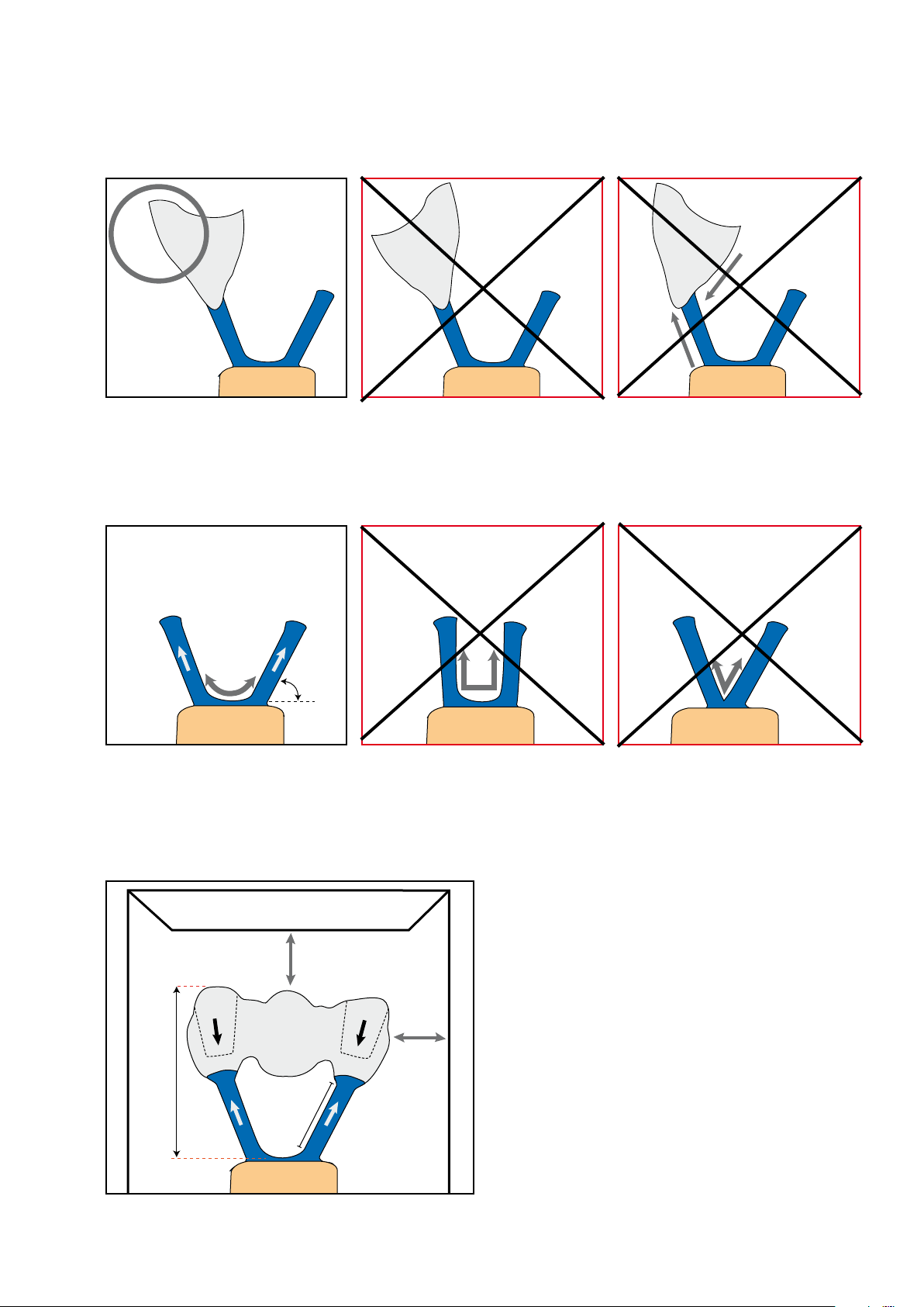
If the crown is viewed from the proximal, the longer side of the object (usually the buccal surface) points outwards. Additionally, the flow of the ceramic material must be observed.
45–60°
45–60°
45–60°
The attachment points of the sprues must be rounded. Observe a 45–60° angle.
Ring gauge
min. 10 mm
max. 15 –16 mm
3 – max. 8 mm
min. 10 mm
60
Page 61
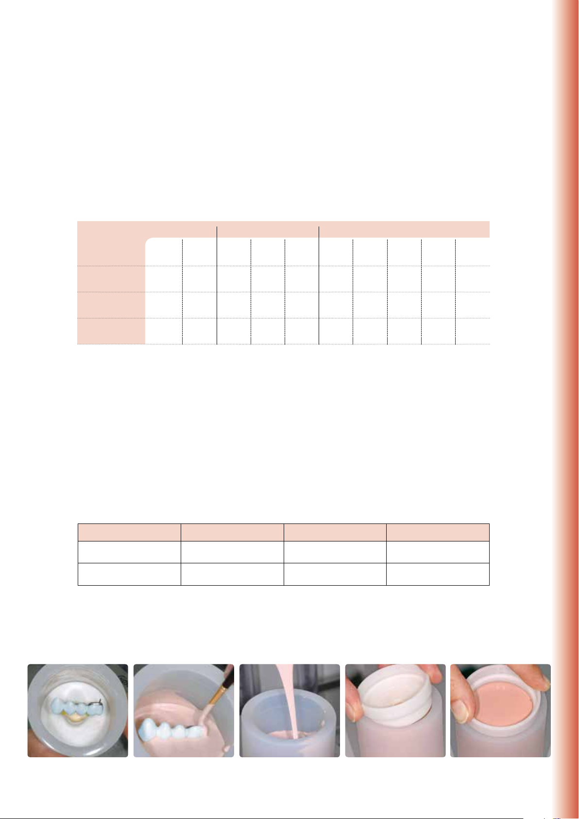
Investing
Investing is carried out using either IPS PressVEST (e.g. overnight) or IPS PressVEST Speed. For that purpose, the IPS Silicone
Ring with the matching investment ring gauge is used. Determine the precise wax weight as follows:
– Weigh the ring base (seal the opening of the ring base with wax).
– Position the objects to be pressed on the ring base and attach them with wax. Weigh again.
– The wax weight is calculated by deducting the weight of the ring base and the weight of the framework (including
opaquer) from the total weight.
100 g 200 g 300 g
IPS InLine PoM – Accurate Press-On Technique
Number of ingots
Individual objects
Bridge pontics
Wax weight
Please refer to the Instructions for Use of the corresponding investment material for the detailed processing parameters.
The following procedure is recommended:
– Do not use a debubblizer on the wax objects. Remove separator thoroughly with oil-free compressed air.
– Mix the investment material. The investment material contains quartz powder. Therefore, avoid the inhalation of dust.
– Use a suitable instrument for the fine investment of the cavity. Make sure that the delicate wax margins are not dam-
aged.
– Carefully place the IPS Silicone Ring on the ring base without damaging the wax objects. The silicone ring must sit flush
on the investment ring base.
– Subsequently, carefully fill the investment ring with investment material up to the marking and position the ring gauge
with a hinged movement.
– Allow the investment ring to set without manipulating it.
– Do not use IPS PressVEST for investment over the weekend to prevent crystallization.
Investment material mixing ratio
Investment material 100 g investment ring 200 g investment ring 300 g investment ring
IPS PressVEST
IPS PressVEST Speed
1 x XS 1 x S 2 x XS
1 2–3 3–4 4–5 5–6 4–5 5–6 6–7 8–9 9–12
0.4 g 0.6 g 1.0 g 1.5 g 2.0 g 1.4 g 2.1 g 3.0 g 4.1 g 5.1 g
13 ml liquid
9 ml dist. water
16 ml liquid
11 ml dist. water
1 x S +
1 x XS
3 3–4 4–6 3–4 4–6 6–7 8–9 9–12
1 x S +
1 x S
26 ml liquid
18 ml dist. water
32 ml liquid
22 ml dist. water
3 x XS 3 x S 6 x XS
3 x XS +
3 x S
39 ml liquid
27 ml dist. water
48 ml liquid
33 ml dist. water
6 x S
61
Page 62

Preheating
After the stipulated setting time of the respective investment material (IPS PressVEST or IPS PressVEST Speed), the investment ring is prepared for preheating as follows:
– Remove the ring gauge and ring base with a turning movement.
– Carefully push the investment ring out of the IPS Silicone Ring.
– Remove rough spots on the bottom surface of the investment ring with a plaster knife. Check the 90° angle. Investment
material residue must not enter the sprues. Blow into the sprues if necessary.
– If several investment rings are preheated together, mark them with the respective ingot shade.
– When placing several investment rings in the preheating furnace using the Speed method, make sure that the furnace
temperature does not drop too much.
Setting time
Preheating furnace temperature
Position of the investment ring in
the furnace
IPS InLine PoM ingots
IPS Alox plunger/IPS One-Way
plunger 300g
Holding time at final temperature
850°C/1562°F
Important
IPS PressVEST
min. 60 min
Start room temperature heat up
to 850 °C/1562 °F / 5 °C/9°F min
towards the rear wall, tipped with the
opening facing down
no preheating
no preheating
at least 90 min
IPS PressVEST Speed
min. 30 min, max. 45 min
Direct 850 °C/1562 °F
towards the rear wall, tipped with the
opening facing down
at least 90 min
If several Speed investments are to be
conducted, they should be invested
consecutively and placed into the pre-
heating furnace at an interval of
approximately 20 minutes. Make sure
that the furnace temperature does not
drop too much when placing the
investment rings into the preheating
furnace. The stipulated holding
time counts from the point when the
preheating temperature has been
reached again.
Position the heating muffle towards the rear wall, tipped with the opening
facing down
Do not preheat the IPS InLine PoM ingot and the IPS One-Way plunger.
In order to ensure smooth working procedures in the laboratory on a daily basis, impeccable functioning of the infrastructure, particularly the preheating furnaces, is essential. This includes their maintenance, cleaning with a vacuum
cleaner in a cool state as well as regular checks of the temperature controls and heating elements, etc. by the manufacturer.
62
Page 63

Selection of ingots
Select the proper ingot. Only seven shades are sufficient to reproduce all the Chromascop, A-D and Bleach shades.
Therefore, it is possible to press fully anatomical restorations for different patient cases in one press cycle. The final tooth
shade is achieved by individual characterization using the IPS InLine System Shade/Stains and Glaze materials.
Given the two ingot sizes, the objects may be optimally fabricated with the corresponding number of IPS InLine PoM ingots
depending on the wax weight.
IPS InLine PoM – Accurate Press-On Technique
BL
1
2
3
4
5
S ingots
XS ingots
S & XS Rohlinge
Ingots &
Rohling &
Touch Up
Touch Up
BL1,BL2, BL3,BL4
A1, B1
110,120, 130,140
A2, B2, C1, D2
210,220, 230,240
A3, A3.5
–
B3,B4
310,320, 330,340
C2,D3,D4
410,420, 430,440
Pressing with the 100g, 200g, 300g IPS Investment Ring System
IPS Alox Plunger for the IPS Investment Ring System 100g, 200g
Provide a cold IPS Alox Plunger and cold IPS InLine PoM
ingots in the desired shade.
Insert the cold IPS InLine PoM ingot with the imprint facing
upwards into the hot investment ring.
Then, place the powder-coated IPS Alox Plunger into the
hot investment ring.
A4,C3,C4
510,520, 530,540
6
Place the hot and completed investment ring in the centre
of the hot press furnace using the IPS Investment Ring
Tongs.
Press START to start the selected program. Once the press program is completed, place the hot invest-
ment ring on the cooling grid using the Investment Ring
Tongs and allow it to cool to room temperature.
Press parameters for IPS InLinePoM ingots in the IPS Investment Ring System 100 g and 200 g
Investment Ring
100 g and 200 g
B
°C/°F
T
°C/°F
H
min
100 g 200 g
t
°C/°F/min
V
°C/°F
1
V
°C/°F
2
EP 500 / V 2.9 700/1292 950/1742 10 20 60/108 500/932 950/1742
EP 600 /
EP 600 Combi
Programat EP 3000 /
Programat EP 5000
700/1292 940/1724 10 20 60/108 500/932 940/1724
700/1292 940/1724 10 20 60/108 500/932 940/1724
*Important: If you enter the program manually, observe the abort criterion.
63
N / E
0
Program 11-20
250 µm/
min.*
250 µm/
min.*
Page 64
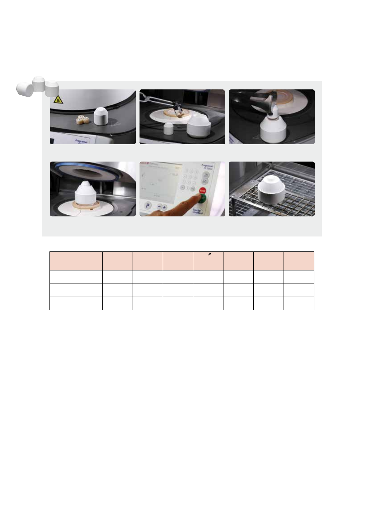
IPS One-Way Plunger 300 g for IPS Investment Ring System 300 g
Provide a cold IPS One-Way Plunger and cold IPS InLine
PoM ingots in the desired shade.
Place the hot and completed investment ring in the centre
of the hot press furnace using the IPS Investment Ring
Tongs
Insert the cold IPS InLine PoM ingots with the imprint facing upwards into the hot investment ring.
Press START to start the selected program. Once the press program is completed, place the hot invest-
Place the cold IPS One-Way Plunger 300 g in the hot
investment ring.
ment ring on the cooling grid using the Investment Ring
Tongs and allow it to cool to room temperature.
Press parameters for IPS InLine PoM ingots in the IPS Investment Ring System 300 g
Investment Ring
300 g
B
°C/°F
T
°C/°F
H
min
300 g
t
°C/°F/min
V
°C/°F
1
V
°C/°F
2
EP 500 / V 2.9 700/1292 960/1760 40 60/108 500/932 960/1760
EP 600 /
EP 600 Combi
Programat EP 3000 /
Programat EP 5000
700/1292 950/1742 40 60/108 500/932 950/1742 50 µm/min.*
700/1292 950/1742 40 60/108 500/932 950/1742 50 µm/min.*
*Important: If you enter the program manually, observe the abort criterion.
N / E
Program 31–51
64
Page 65

Divesting
Once the investment ring has cooled to room temperature (approx. 60 min), divest as follows:
– Mark the length of the Alox plunger on the cooled investment ring.
– Separate the investment ring using a separating disk. This predetermined breaking
point enables reliable separation of the investment material and the ceramic material.
– Always use polishing beads to divest the pressed objects (rough and fine divestment).
Do not use Al2O3 .
– Rough divestment is carried out with polishing beads at 4 bar (60 psi) pressure.
– Fine divestment is carried out with polishing beads at 1–1.5 bar (15–22 psi) pressure.
– Observe the blasting direction and distance to prevent damage to the object margins
during divestment. Cover the marginal areas thoroughly with the glove.
IPS InLine PoM – Accurate Press-On Technique
Separate the investment ring using a separating disk.
Mark the length of the Alox plunger.
The Alox plunger is already very clean if it is removed with tongs from the investment material. Check the cleanness and blast with Al
Sandblasting the objects
65
if required.
2O3,
Page 66
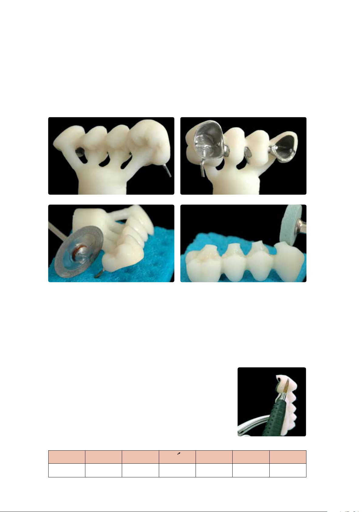
Separating / finishing
After separation of the sprues and smoothing of the attachment points, the pressed object is fitted to the master model.
For that purpose, the usual rotary instruments (as those used for IPS Empress) are used (without pressure and overheating). After that, carefully sandblast the restoration. Finally, clean the restoration under running water or with steam.
Dry thoroughly with oil-free air.
Bridge with sprues
Special attention is required for separating the palatal metal retention pin. Make sure to separate and polish the retention pin carefully after glazing without creating too much heat.
Adjustments with IPS InLine PoM Touch-Up
For minor shape adjustments, such as incompletely pressed margins or occlusal surfaces, the 7 Touch-Up materials are
available in the respective ingot shade. The Touch-Up materials must only be used for metalsupported IPS InLine PoM restorations.
Processing
– The restoration must be free of dirt and grease prior to adjustment. For that
purpose, clean the restoration thoroughly with a steam jet.
– Apply the IPS InLine PoM Touch-Up material mixed with IPS InLine System Build-Up
Liquid on the missing, cleaned areas using a brush and slightly blot with an absorbent
cloth.
– Place the restoration on the firing tray and fire it.
– Next, finish the restoration or apply second Touch-Up adjustments and fire with the
same parameters.
Firing parameters for IPS InLine PoM Touch-Up
T
°C/°F
B
°C/°F
S
min
t
°C/°F/min
H
min
Adjustment with IPS InLine PoM Touch Up
V
°C/°F
1
V
°C/°F
2
840/1544 403/757 4 60/108 1 450/842 839/1542
66
Page 67

Individual finishing
Finishing and preparing for the Stains and Glaze firing
Before the Stains and Glaze firing, the restoration has to be prepared as follows:
– Finish the restoration using diamond grinders and give it a
true-to-nature shape and surface structure, such as growth
lines and convex/concave areas.
– Areas which should exhibit a higher gloss after Glaze firing
(e.g. pontic rests) can be smoothed out and prepolished using
silicone disks.
– If gold and/or silver dust was used to visualize the surface
texture, the restoration has to be thoroughly cleaned with
steam. Make sure to remove all gold or silver dust in order to
avoid any discolouration after firing.
IPS InLine PoM – Accurate Press-On Technique
The true-to-nature shape and surface texture are designed.
Shade
A-D
Chromascop
Stains and Characterization firing
Before the Stains and Characterization firing, the restoration must be free of dirt and grease. Any contamination after
cleaning must be prevented. The following steps must be observed:
– For better wetting of the stains, IPS InLine System Glaze and Stains liquid may be slightly agitated on the surface.
– If a more intensive shade effect is desired, it is achieved by several staining procedures and repeated firing. The
application of too many stains results in an unnatural shade effect.
– The cusps and fissures can be individualized using Stains.
– The basic chromatic shade is supported with the corresponding Shade material (see table).
Shade combination table for IPS InLine One / IPS InLine / IPS InLine PoM
1
A1, B1, B2
110, 120, 130
BL1, BL2, BL3,
BL4
2
A2, A3, A3.5
140,
210, 220, 230,
240
3
B3, B4, D4
310, 320, 330
4
A4
340, 540
Firing parameters for the IPS InLine System Shade/Stains firing
T
°C/°F
B
°C/°F
S
min
5
C1, D2, D3
–
t
°C/°F/min
6
C2, C3, C4
410, 420,
430, 440,
510
H
min
7
–
520, 530
V
1
°C/°F
SI1
A1, A2, A3, B1,
B2, B3, B4
110–140, 210,
220, 310, 320,
BL1–BL4
A3.5, A4, C1,
C2, C3, C4, D2,
230, 240, 330,
340, 410–440,
V
2
°C/°F
SI2
D3, D4
510–540
800/1472 403/757 6 60/108 1 450/842 799/1470
Note:
All the firing cycles for stains and characterization as well as the Glaze firing in conjunction with IPS InLine PoM
restorations are carried out at 800 °C / 1472 °F.
Important
All InLine System products such as Opaquer, Shade, Stains, Glaze, Add-On 690 °C and Liquids are compatible
with IPS InLine PoM.
67
Page 68

Shade adjustment with IPS InLine System Shade and Stains
These stains may be fired in a separate Stains firing. Minor shade adjustments and individual characterizations may also be
fired in the Glaze firing.
Dispense the desired quantity of IPS InLine System Shade and dilute and mix with IPS InLine System Glaze and Stains Liquid
to the desired consistency. Pooling should be avoided and the material must not be applied too thickly. If a more intensive
shade effect is desired, it is achieved by several staining procedures and repeated firing. The application of too many stains
results in an unnatural shade effect.
Firing parameters for the IPS InLine System Shade/Stains firing (Stains and Characterization firing)
T
°C/°F
800/1472 403/757 6 60/108 1 450/842 799/1470
Additional Stains and Characterization firing cycles can be conducted with the same firing parameters.
B
°C /°F
min
S
t
°C//°Fmin
H
min
V
1
°C/°F
V
2
°C/°F
Glaze firing
After the Stains and Characterization firing with IPS InLine System Shade/Stains, the Glaze firing is conducted.
– Remove IPS InLine System Glaze paste from the syringe and mix thoroughly. If a different consistency is desired, adjust
the consistency by diluting the material with IPS InLine System Glaze and Stains Liquid. Next, apply the Glaze material in
the usual manner using a brush. Make sure not to apply the Glaze material either in too thick or too thin layers.
– Minor shade adjustments may be carried out together with the Glaze firing.
Firing parameters for the Glaze firing
T
°C/°F
800/1472 403/757 6 60/108 2 450/842 799/1470
When working with a furnace from another manufacturer, these parameters have to be adjusted accordingly! Finally, the
shade of the completed restoration is checked.
If less gloss is desired, the holding time can be reduced to 1 minute.
If the gloss is unsatisfactory after the first Glaze firing, further Glaze firing procedures
may be conducted using the same firing parameters.
B
°C/°F
S
min
t
°C/°F/min
H
min
V
1
°C/°F
V
2
°C /°F
68
Page 69
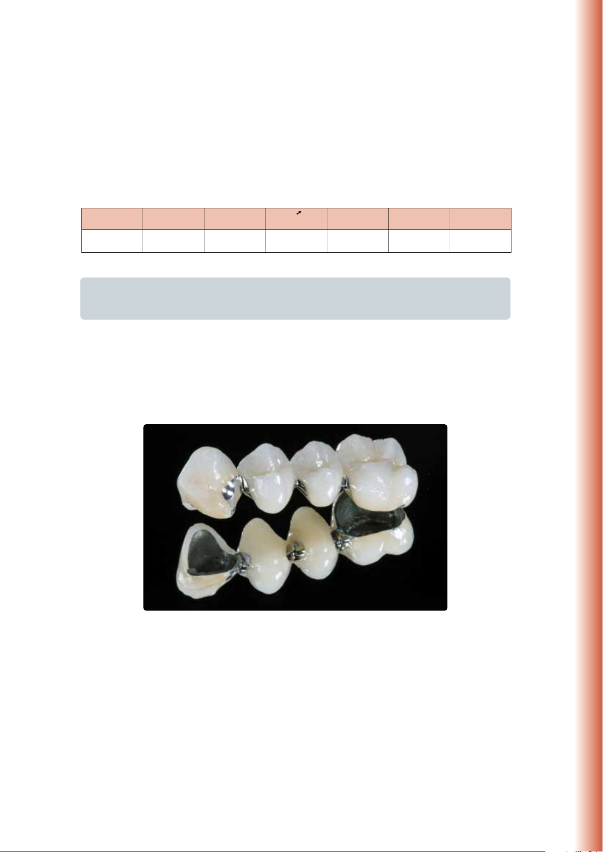
Add-On after Glaze firing
After the completion of a restoration, small adjustments, such as contact points, pontic rests, shoulder adjustments, may
be necessary.
Mix the IPS InLine System Add-On 690 °C/1274 °F material with the desired build-up liquid, apply on the missing areas,
and fire.
Firing parameters for IPS InLine System Add-On 690°C/1274°F after Glaze firing
T
°C/°F
690/1274 403/757 4 60/108 1 450/842 689/1272
Important
Special attention is required for separating the “retention pins”. Make sure to separate and polish the
retainer carefully after glazing without creating too much heat.
B
°C/°F
min
S
t
°C/°F/min
H
min
V
1
°C/°F
V
2
°C/°F
IPS InLine PoM – Accurate Press-On Technique
Individually designed and characterized bridge made of IPS InLine PoM
69
Page 70

®
InLine
IPS
– Veneers
The following chapter shows the step-by-step layering of veneers on refractory dies.
Important: After each working step, the master model has to be immersed in water for about 5–10 minutes, depending
on the size.
Tip:
For the veneer fabrication, smaller working steps and several intermediate firing cycles are recommended.
Model fabrication
Fabricate a duplicate model using a commercially available refractory
die material, e.g. BegoForm® from Bego, Cosmotech VEST from GC
or G-CERATM VEST from GC (observe the instructions of the
manufacturer).
Important: Correct processing and properly degassed dies are an
important prerequisite for accurately fitting veneers.
Wash firing
After degassing the refractory dies, apply IPS InLine Add-On mixed
with the IPS InLine System Glaze and Stains Liquid in a thin layer
and fire.
Firing parameters for IPS InLine Add-On / IPS InLine System
Glaze
T
°C/°FB°C/°F
830/
1526
403/
757
S
min
4 60/108 1
t
°C/°F/minHmin
V
°C/°F
450/
842
1
V
°C/°F
829/
1524
2
Cervical firing
Build up the marginal areas using a mixture of IPS InLine Dentin
and, for example, Occlusal Dentin brown.
Firing parameters for the Cervical firing
T
°C
940/
1724
B
°C
403/
757
S
mint °C/ minHmin
8 60/108 1
V
°C
450/
842
V
1
2
°C
939/
1722
Dentin/Impulse firing
Internal layering is modelled to the natural characteristics and consists of a dentin build-up and various effects. Individual layering with
the Impulse materials enables mamelons, opalescence and translucent effects to be achieved.
Firing parameters for the Dentin / Impulse firing
T
°C
940/
1724
70
B
°C
403/
757
S
mint °C /minHmin
8 60/108 1
V
°C
450/
842
V
1
°C
939/
1722
2
Page 71

Incisal firing
Subsequently, build up the outer enamel layer and fire.
Firing parameters for the Incisal firing
T
°C/°F B°C/°F Smint °C /°F/minHmin
930/
1706
403/
757
8 60/108 1
V
1
°C/°F
450/
842
°C/°F
929/
1704
Glaze firing
Apply the IPS InLine System Glaze paste on the surface and fire.
Firing parameters for the Glaze firing
T
°C/°F B°C/°F Smint °C/°F/minHmin
860/
1580
403/
757
8 60/108 1
V
1
°C/°F
450/
842
°C/°F
859/
1578
IPS InLine – Veneers
V
2
V
2
Divesting the veneers
Remove large amounts of die material using a grinding disk. Fine
divestment is carried out with polishing beads at 1 bar (30 psi)
pressure.
Conditioning the veneers for adhesive cementation
Etch the inner aspect of the veneer with IPS Ceramic Etching Gel
for 120 seconds in preparation for adhesive cementation. Next,
thoroughly rinse the object with running water and dry.
Important: IPS InLine veneers must be placed with the adhesive
technique.
71
Page 72

InLine® One
IPS
/ InLine®
IPS
/ InLine® PoM
IPS
General Information
Cementation
As usual, your dentist may use a conventional cementation protocol for metal-supported IPS InLine restorations or use
adhesive cementation for metal-supported restorations with a ceramic shoulder as well as IPS InLine veneers.
Glass ionomer cements, such as Vivaglass CEM, or self-adhesive composite cements are suitable for conventional cementation. For an adhesive cementation protocol, we recommend the Multilink Automix universal composite.
Esthetic
luting composites
Material Variolink
Polymerization light-curing light-/dual-curing dual-curing self-curing
Method Adhesive: Adhesive: Adhesive: Self-adhesive
Syntac or ExciTE Syntac or ExciTE DSC Multilink Primer A/B
Total-Etch Total-Etch self-etching
IPS InLine One
One-layer metal-ceramic
IPS InLine
Conventional metal-ceramic
IPS InLine PoM
Press-on-Metal ceramic
IPS InLine Veneers
Please observe the corresponding Instructions for Use.
Conditioning of the restoration
Metal-ceramic restorations
– Sandblast the inner aspects of the crown (parameters according to the instructions of the manufacturer of the
restorative material) until an even mat surface has been achieved.
– If necessary, clean the restoration in an ultrasonic unit for about 1 minute.
– Thoroughly rinse with water spray and dry with oil-free air.
– Important: In order to create a strong bond, do not clean the metal surfaces with phosphoric acid.
– Apply Monobond Plus with a brush or a Microbrush to the pre-treated surfaces, let it react for 60 s and then disperse
with a strong stream of air.
®
Veneer Variolink® II Multilink® Automix SpeedCEM
–
–
–
–
–
–
– –
✓ Recommended product combination
– Not recommended
Universal luting
composite
Self-adhesive
composite cement
IPS InLine Veneers
– Etch the inner aspect of the veneer with IPS Ceramic Etching Gel for 120 seconds.
– Thoroughly rinse with water spray and dry with oil-free air.
– Apply Monobond Plus with a brush or a Microbrush to the pre-treated surfaces, let it react for 60 s and then disperse
with a strong stream of air.
72
Page 73

InLine® One – One-layer metal-ceramic
IPS
Firing Parameters
IPS InLine One
One-layer metal-ceramic
st
+ 2nd Opaquer firing, powder opaquer 960/1760 403/757 4 100/180 2 450/842 959/1758
1
st
+ 2nd Opaquer firing, paste opaquer 930/ 1706 403/757 6 100/180 2 450/842 929/1704
1
1st Dentcisal firing 910/1670 403/757 4 60/108 1 450/842 909/1668
2nd Dentcisal firing 900/1652 403/757 4 60/108 1 450/842 899/1650
Shade/Stains firing 850/1562 403/757 6 60/108 1 450/842 849/1560
Glaze firing 850/1562 403/757 6 60/108 2 450/842 849/1560
Add-On after Glaze firing (690 °C/1274°F) 690/1274 403/757 4
T = Firing temperature °C/°F
B = Stand-by temperature °C/°F
S = Closing time in minutes
➚ = Heating rate °C/°F/min
t
H = Holding time
1
= Vacuum on temperature °C/°F
V
2
= Vacuum off temperature °C/°F
V
T
°C/°F
B
°C/°F
min
S
t
°C/°F/minHmin
60/108 1 450/842 689/1272
V
1
°C/°F
V
°C/°F
These firing parameters are guidance values. They are valid for the Programat furnaces from Ivoclar Vivadent.
Deviations (approx. +/- 10 °C/18 °F) may occur:
– Depending on the furnace generation.
– If ceramic furnaces from other manufacturers are used.
– In case of regional differences in the power supply or if several electrical devices are operatated on the same circuit.
2
73
Page 74

®
InLine
IPS
– Conventional metal-ceramic
Firing Parameters
IPS InLine
Conventional metal-ceramic
st
+ 2nd Opaquer firing, powder opaquer 960/1760 403/757 4 100/180 2 450/842 959/1758
1
st
+ 2nd Opaquer firing / Gingiva, paste opaquer 930/1706 403/757 6 100/180 2 450/842 929/1704
1
st
+ 2nd Margin firing 930/1706 403/757 4 60/108 1 450/842 929/1704
1
st
Dentin and Incisal firing / Gingiva 910/1670 403/757 4 60/108 1 450/842 909/1668
1
nd
Dentin and Incisal firing / Gingiva 900/1652 403/757 4 60/108 1 450/842 899/1650
2
Margin Add-On firing 900/1652 403/757 4 60/108 1 450/842 899/1650
Corrective firing after Dentin and Incisal firing, Add-On
Shade / Stains firing 850/1562 403/757 6 60/108 1 450/842 849/1560
Glaze firing 850/1562 403/757 6 60/108 2 450/842 849/1560
Add-On after Glaze firing (690 °C/1274) 690/1274 403/757 4 60/108 1 450/842 689/1274
T = Firing temperature °C/°F
B = Stand-by temperature °C/°F
S = Closing time in minutes
➚ = Heating rate °C/°F/min
t
H = Holding time
1
= Vacuum on temperature °C/°F
V
2
= Vacuum off temperature °C/°F
V
T
°C/°F
860/1580 403/757 4 60/108 1 450/842 859/1578
B
°C/°F
min
S
t
°C/°F/minHmin
V
°C/°F
1
V
°C/°F
These firing parameters are guidance values. They are valid for the Programat furnaces from Ivoclar Vivadent.
Deviations (approx. +/- 10 °C/18 °F) may occur:
– Depending on the furnace generation.
– If ceramic furnaces from other manufacturers are used.
– In case of regional differences in the power supply or if several electrical devices are operatated on the same circuit.
2
74
Page 75

®
InLine
IPS
PoM – Press-on-Metal ceramic
Investment material mixing ratio
Investment material 100 g investment ring 200 g investment ring 300 g investment ring
IPS PressVEST
IPS PressVEST Speed
13 ml liquid
9 ml dist. water
16 ml liquid
11 ml dist. water
26 ml liquid
18 ml dist. water
32 ml liquid
22 ml dist. water
39 ml liquid
27 ml dist. water
48 ml liquid
33 ml dist. water
Press parameters
Press parameters for IPS InLine PoM ingots in the IPS Investment Ring System 100 g and 200 g
Investment Ring
100 g and 200 g
°C/°F
B
T
°C/°F
EP 500 / V 2.9 700/1292 950/1742 10 20 60/108 500/932 950/1742
EP 600 /
EP 600 Combi
Programat EP 3000 /
Programat EP 5000
700/1292 940/1724 10 20 60/108 500/932 940/1724
700/1292 940/1724 10 20 60/108 500/932 940/1724
H
min
100 g 200 g
t
°C/°F/min
V
°C/°F
1
V
°C/°F
2
N / E
0
Program 11-20
250 µm/
min.*
250 µm/
min.*
*Important: If you enter the program manually, observe the abort criterion.
Press parameters for IPS InLinePoM ingots in the IPS Investment Ring System 300 g
Investment Ring
300 g
°C/°F
B
T
°C/°F
H
min
300 g
t
°C/°F/min
V
°C/°F
1
V
°C/°F
2
EP 500 / V 2.9 700/1292 960/1760 40 60/108 500/932 960/1760
EP 600 /
EP 600 Combi
Programat EP 3000 /
Programat EP 5000
700/1292 950/1742 40 60/108 500/932 950/1742 50 µm/min.*
700/1292 950/1742 40 60/108 500/932 950/1742 50 µm/min.*
*Important: If you enter the program manually, observe the abort criterion.
75
N / E
Programm 31–51
Page 76
Firing parameters
IPS InLine PoM
Press-on-Metal Keramik
st
+ 2nd Opaquer firing, powder opaquer 960/1760 403/757 4 100/180 2 450/842 959/1758
1
st
+ 2nd Opaquer firing, paste opaquer 930/1706 403/757 6 100/180 2 450/842 929/1704
1
T
°C/°F
B
°C/°F
S
mint °C/°F/minHmin
V
°C/°F
1
V
2
°C/°F
Touch-Up firing 840/1544 403/757 4 60/108 1 450/842 839/1542
Shade/Stains firing 800/1472 403/757 6 60/108 1 450/842 839/1542
Glasur-Brand 800/1472 403/757 6 60/108 2 450/842 839/1542
Add-On after Glaze firing (690 °C/1274 °F) 690/1274 403/757 4 60/108 1 450/842 689/1272
T = Firing temperature °C/°F
B = Stand-by temperature °C/°F
S = Closing time in minutes
➚ = Heating rate °C/°F/min
t
H = Holding time
1
= Vacuum on temperature °C/°F
V
2
= Vacuum off temperature °C/°F
V
These firing parameters are guidance values. They are valid for the Programat furnaces from Ivoclar Vivadent.
Deviations (approx. +/- 10 °C/18 °F) may occur:
– Depending on the furnace generation.
– If ceramic furnaces from other manufacturers are used.
– In case of regional differences in the power supply or if several electrical devices are operatated on the same circuit.
76
Page 77

®
InLine
IPS
– Veneer
Firing parameters
IPS InLine
Veneers
Wash Firing 830/1526 403/757 4 60/108 1 450/842 829/1524
Cervical firing 940/1724 403/757 8 60/108 1 450/842 939/1722
Dentin / Impulse firing 940/1724 403/757 8 60/108 1 450/842 939/1722
Incisal firing 930/1706 403/757 8 60/108 1 450/842 929/1704
Glaze firing 860/1580 403/757 8 60/108 1 450/842 859/1578
T = Firing temperature °C/°F
B = Stand-by temperature °C/°F
S = Closing time in minutes
➚ = Heating rate °C/°F/min
t
H = Holding time
1
= Vacuum on temperature °C/°F
V
2
= Vacuum off temperature °C/°F
V
T
°C/°F
B
°C/°F
S
mint °C/°F/minHmin
V
°C/°F
1
V
2
°C/°F
These firing parameters are guidance values. They are valid for the Programat furnaces from Ivoclar Vivadent.
Deviations (approx. +/- 10 °C/18 °F) may occur:
– Depending on the furnace generation.
– If ceramic furnaces from other manufacturers are used.
– In case of regional differences in the power supply or if several electrical devices are operatated on the same circuit.
77
Page 78

Opaquer
®
InLine
IPS
Combination Tables
A–D shades
reddish-brown reddish-yellow
Intensive
Opaquer
Margin
Intensive
Margin
Cervical
Dentin
Deep
Dentin
A1
A1
A1
A2 A3 A3.5 A4
A2
A2
A3 A3.5
yellow orange-pink
A3
A3.5
A4
A4
B1
white
B1
B1
B2
B2 B3
B2 B3
B3
B4
violet
B4
B4
Dentin
Transpa
Incisal
Transparent
TI1
A1
A2
TI1
A3
TI2
clear clear
A3.5
TI2
A4
TI3
78
TI1
B1
B2
TI1
TI1
B3
B4
TI2
Page 79

shades of grey reddish-grey
C1
C1
add-on opaque
C2
brown
C2
C3
C3
C4
incisal
C4
D2
D2/D3
D3
D2/D3
orange
D2/D3
D4
D4
TI1
C1
C1
C2
C2 C3
TI3 TI3
clear clear
C3
C4
C4
TI3
D2/D3
D2
TI3
79
D3
TI3
D4
D4
TI3
Page 80

®
InLine
IPS
Chromascop shades
Opaquer
Intensive
Opaquer
Margin
Intensive
Margin
white
110 120 130 140
110 120 130 140
yellow
210 220
white
210 220 230 240
yellow orange-pink
230
240
310
violet
310
Deep
Dentin
Dentin
Incisal
Transparent
110 120
110 120 130 140
I1
I1
130
I1
clear clear
140
210 220
210 220 230 240
I2
I2 I2
230 240
I3
I3
310
310
I3
80
Page 81

light-brown
grey
dark-brown
320 330 340
brown
320
330
add-on opaque orange
340
410 420 430 440
incisal
410 420 430
410 420 430
440
440
510 520 530 540
510 520 530 540
510 520 530 540
320 330 340
I3
clear clear clear
I3
I3 I3
410 420
I3
430
440
I3
I3
81
510
I3
520
I3
530 540
I3
I3
Page 82

Independent of any shade system
Impulse Kit
Occlusal Dentin
Mamelon
Opal Effect
Transparent
Cervical Incisal
Gingiva Kit
Gingiva Opaquer
orange
light
OE 1
neutral blue brown-grey
orange
brown
salmon yellow-orange
OE 2 OE 3
yellow
Gingiva
OE 4 OE 5
OE violet
Intensive Gingiva
Shade / Stains Kit
Shade
AD shades
A1, B1, B2 A2, A3, A3.5 B3, B4, D4 A4 C1, D2, D3 C2,C3,C4 –
Chromascop
110, 120, 130 140, 210, 310, 320, 340 340, 540 – 410, 420, 520, 530
BL3, BL4
Shade Incisal
Stains
pink
IG1
1
BL1, BL2,
SI1
basic blue
G1
IG2
2
220, 230, 240 430, 440, 510
SI2
basic red
IG3
3
basic yellow
G2
IG4
4
black
G3
5 6 7
crackliner
G4 G5
grey
khaki
mahogany
maroon
olive
82
orange
vanilla
white yellow
Page 83

Bleach Kit BL
Opaquer
Margin
Deep Dentin
Dentin
Incisal
Add-On
BL1/BL2
BL1
BL1
BL1 BL2 BL3 BL4
BL
BL
BL3/BL4
BL4
BL4
The Margin materials are only available in shades BL1 and BL4.
The shades BL2 and BL3 are achieved with the following mixing ratios:
BL2 = 2/3 BL1 : 1/3 BL4
BL3 = 1/3 BL1 : 2/3 BL4
The Deep Dentin materials are only available in shades BL1 and BL4.
The shades BL2 and BL3 are achieved with the following mixing ratios:
BL2 = 2/3 BL1 : 1/3 BL4
BL3 = 1/3 BL1 : 2/3 BL4
83
Page 84

InLine
IPS
®
PoM
Opaquer AD A1, B1 A2, B2, C1, D2 A3, A3.5 B3, B4 C2, D3, D4 A4, C3, C4
Opaquer
Chromascop
Ingots
Touch-Up
InLine
IPS
Opaquer AD A1, B1 A2, B2, C1, D2 A3, A3.5 B3, B4 C2, D3, D4 A4, C3, C4
Opaquer
Chromascop
Dentcisal
BL1, BL2, BL3,
BL4
BL 1 2 3 4 5 6
®
110, 120,
130, 140
210, 220,
230, 240
310, 320,
330, 340
410, 420,
430, 440
One
BL1, BL2, BL3,
BL4
BL 1 2 3 4 5 6
110, 120,
130, 140
210, 220,
230, 240
310, 320,
330, 340
410, 420,
430, 440
510, 520,
530, 540
510, 520,
530, 540
84
Page 85
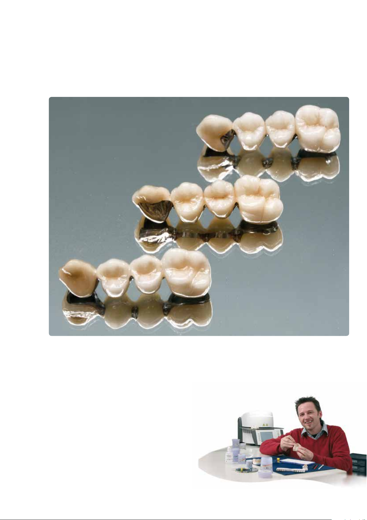
InLine® One
IPS
One-layer metal-ceramic
Finished metal, shape and shade
®
InLine
IPS
Conventional metal-ceramic
InLine® PoM
IPS
Press-on-Metal ceramic
The dental lab work was carried out by
Dieter Grübel, ICDE/Schaan.
85
Page 86

86
Page 87

87
Page 88

Ivoclar Vivadent worldwide
Ivoclar Vivadent AG
Bendererstrasse 2
9494 Schaan
Liechtenstein
Tel. +423 235 35 35
Fax +423 235 33 60
www.ivoclarvivadent.com
Ivoclar Vivadent Pty. Ltd.
1 – 5 Overseas Drive
P.O. Box 367
Noble Park, Vic. 3174
Australia
Tel. +61 3 9795 9599
Fax +61 3 9795 9645
www.ivoclarvivadent.com.au
Ivoclar Vivadent Ltda.
Alameda Caiapós, 723
Centro Empresarial Tamboré
CEP 06460-110 Barueri – SP
Brazil
Tel. +55 11 2424 7400
Fax +55 11 3466 0840
www.ivoclarvivadent.com.br
Ivoclar Vivadent Inc.
1-6600 Dixie Road
Mississauga, Ontario
L5T 2Y2
Canada
Tel. +1 905 670 8499
Fax +1 905 670 3102
www.ivoclarvivadent.us
Ivoclar Vivadent Shanghai
Trading Co., Ltd.
2/F Building 1, 881 Wuding Road,
Jing An District
200040 Shanghai
China
Tel. +86 21 6032 1657
Fax +86 21 6176 0968
www.ivoclarvivadent.com
Ivoclar Vivadent Marketing Ltd.
Calle 134 No. 7-B-83, Of. 520
Bogotá
Colombia
Tel. +57 1 627 3399
Fax +57 1 633 1663
www.ivoclarvivadent.co
Ivoclar Vivadent SAS
B.P. 118
F-74410 Saint-Jorioz
France
Tel. +33 4 50 88 64 00
Fax +33 4 50 68 91 52
www.ivoclarvivadent.fr
Ivoclar Vivadent GmbH
Dr. Adolf-Schneider-Str. 2
D-73479 Ellwangen, Jagst
Germany
Tel. +49 7961 889 0
Fax +49 7961 6326
www.ivoclarvivadent.de
Wieland Dental + Technik
GmbH & Co. KG
Schwenninger Strasse 13
D-75179 Pforzheim
Germany
Tel. +49 7231 3705 0
Fax +49 7231 3579 59
www.wieland-dental.com
Ivoclar Vivadent Marketing (India)
Pvt. Ltd.
503/504 Raheja Plaza
15 B Shah Industrial Estate
Veera Desai Road, Andheri (West)
Mumbai, 400 053
India
Tel. +91 22 2673 0302
Fax +91 22 2673 0301
www.ivoclarvivadent.in
Ivoclar Vivadent s.r.l.
Via Isonzo 67/69
40033 Casalecchio di Reno (BO)
Italy
Tel. +39 051 6113555
Fax +39 051 6113565
www.ivoclarvivadent.it
Ivoclar Vivadent K.K.
1-28-24-4F Hongo
Bunkyo-ku
Tokyo 113-0033
Japan
Tel. +81 3 6903 3535
Fax +81 3 5844 3657
www.ivoclarvivadent.jp
Ivoclar Vivadent Ltd.
12F W-Tower, 1303-37
Seocho-dong, Seocho-gu,
Seoul 137-855
Republic of Korea
Tel. +82 2 536 0714
Fax +82 2 596 0155
www.ivoclarvivadent.co.kr
Ivoclar Vivadent S.A. de C.V.
Av. Insurgentes Sur No. 863,
Piso 14, Col. Napoles
03810 México, D.F.
México
Tel. +52 55 5062 1000
Fax +52 55 5062 1029
www.ivoclarvivadent.com.mx
Ivoclar Vivadent BV
De Fruittuinen 32
2132 NZ Hoofddorp
Netherlands
Tel. +31 23 529 3791
Fax +31 23 555 4504
www.ivoclarvivadent.com
Ivoclar Vivadent Ltd.
12 Omega St, Rosedale
PO Box 303011 North Harbour
Auckland 0751
New Zealand
Tel. +64 9 914 9999
Fax +64 9 914 9990
www.ivoclarvivadent.co.nz
Ivoclar Vivadent Polska Sp. z o.o.
Al. Jana Pawla II 78
00-175 Warszawa
Poland
Tel. +48 22 635 5496
Fax +48 22 635 5469
www.ivoclarvivadent.pl
Ivoclar Vivadent Marketing Ltd.
Prospekt Andropova 18 korp. 6/
office 10-06
115432 Moscow
Russia
Tel. +7 499 418 0300
Fax +7 499 418 0310
www.ivoclarvivadent.ru
Ivoclar Vivadent Marketing Ltd.
Qlaya Main St.
Siricon Building No.14, 2
Office No. 204
nd
Floor
P.O. Box 300146
Riyadh 11372
Saudi Arabia
Tel. +966 11 293 8345
Fax +966 11 293 8344
www.ivoclarvivadent.com
Ivoclar Vivadent S.L.U.
C/ Ribera del Loira nº 46, 5ª planta
28042 Madrid
Spain
Tel. + 34 913 757 820
Fax + 34 913 757 838
www.ivoclarvivadent.es
Ivoclar Vivadent AB
Dalvägen 14
S-169 56 Solna
Sweden
Tel. +46 8 514 939 30
Fax +46 8 514 939 40
www.ivoclarvivadent.se
Ivoclar Vivadent Liaison Office
: Tesvikiye Mahallesi
Sakayik Sokak
Nisantas’ Plaza No:38/2
Kat:5 Daire:24
34021 Sisli – Istanbul
Turkey
Tel. +90 212 343 0802
Fax +90 212 343 0842
www.ivoclarvivadent.com
Ivoclar Vivadent Limited
Ground Floor Compass Building
Feldspar Close
Warrens Business Park
Enderby
Leicester LE19 4SE
United Kingdom
Tel. +44 116 284 7880
Fax +44 116 284 7881
www.ivoclarvivadent.co.uk
Ivoclar Vivadent, Inc.
175 Pineview Drive
Amherst, N.Y. 14228
USA
Tel. +1 800 533 6825
Fax +1 716 691 2285
www.ivoclarvivadent.us
Manufacturer:
Ivoclar Vivadent AG, 9494 Schaan/Liechtenstein
www.ivoclarvivadent.com
Date information prepared: 2014-03, Rev. 1
These materials have been developed solely for use in dentistry. Processing should be carried out strictly
according to the Instructions for Use. Liability cannot be accepted for damages resulting from failure to
observe the Instructions or the stipulated area of application. The user is responsible for testing the products
for their suitability and use for any purpose not explicitly stated in the Instructions. These regulations also
apply if the materials are mixed or used in conjunction with products of other manufacturers.
Printed in Liechtenstein
© Ivoclar Vivadent AG, Schaan / Liechtenstein
633561/en
 Loading...