

Page 1
Press
Abutment Solutions
all ceramic
all you need
instructions for use
Page 2

Table of Contents
3 Product Information
Material
Uses
Composition
6 Fabrication of Hybrid Abutments and Hybrid Abutment Crowns
Treatment/fabrication process
Shade – tooth shade, preparation shade/abutment shade
Model preparation
Selecting a Ti base
Layer thicknesses of the ceramic components
Modeling
Sprueing
Investing
Preheating
Pressing
Divesting
Removing the reaction layer
Finishing
Stain and Characterization firing
Glaze firing
Crown on hybrid abutment
32 Optional: Clinical Try-in
Temporarily securing the pressed object on the Ti base
Clinical try-in
application procedure
37 Permanent Cementation
Pre-treatment of the Ti base
Preparing the pressed object
Cementation with Multilink Implant
43 Seating and Aftercare
Sterilization
Intraoral preparation
Seating the hybrid abutment and crown
Seating the hybrid abutment crown
Care notes – Implant Care
50 General Information
Frequently Asked Questions
Material Selection Table
Press and Firing Parameters
Clinical Cases
2
Page 3
®
IN ST RUC TI ONS FO R U SE
Press
all ceramic
all you need
emax Press-VA 2009-d_emax Press-VA-d.qxd 22.09.11 14:13 Seite 1
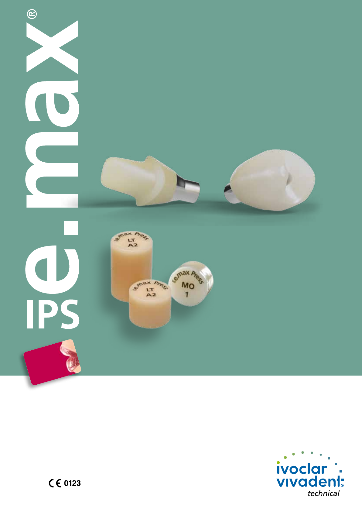
e.max
IPS
Press Abutment Solutions
Product Information
Press ceramics have been synonymous with esthetics, accuracy of fit, shape and function for decades. The IPS e.max Press lithium disilicate
(LS2) glass-ceramic additionally offers an outstanding strength of 400 MPa. The already extensive indication range from thin veneers (0.3 mm)
and monolithic molar crowns to anterior and premolar bridges is now expanded to include hybrid abutment restorations.
With IPS e.max Press, you can fabricate such restorations in combination with a titanium base (Ti base). Two different approaches are available:
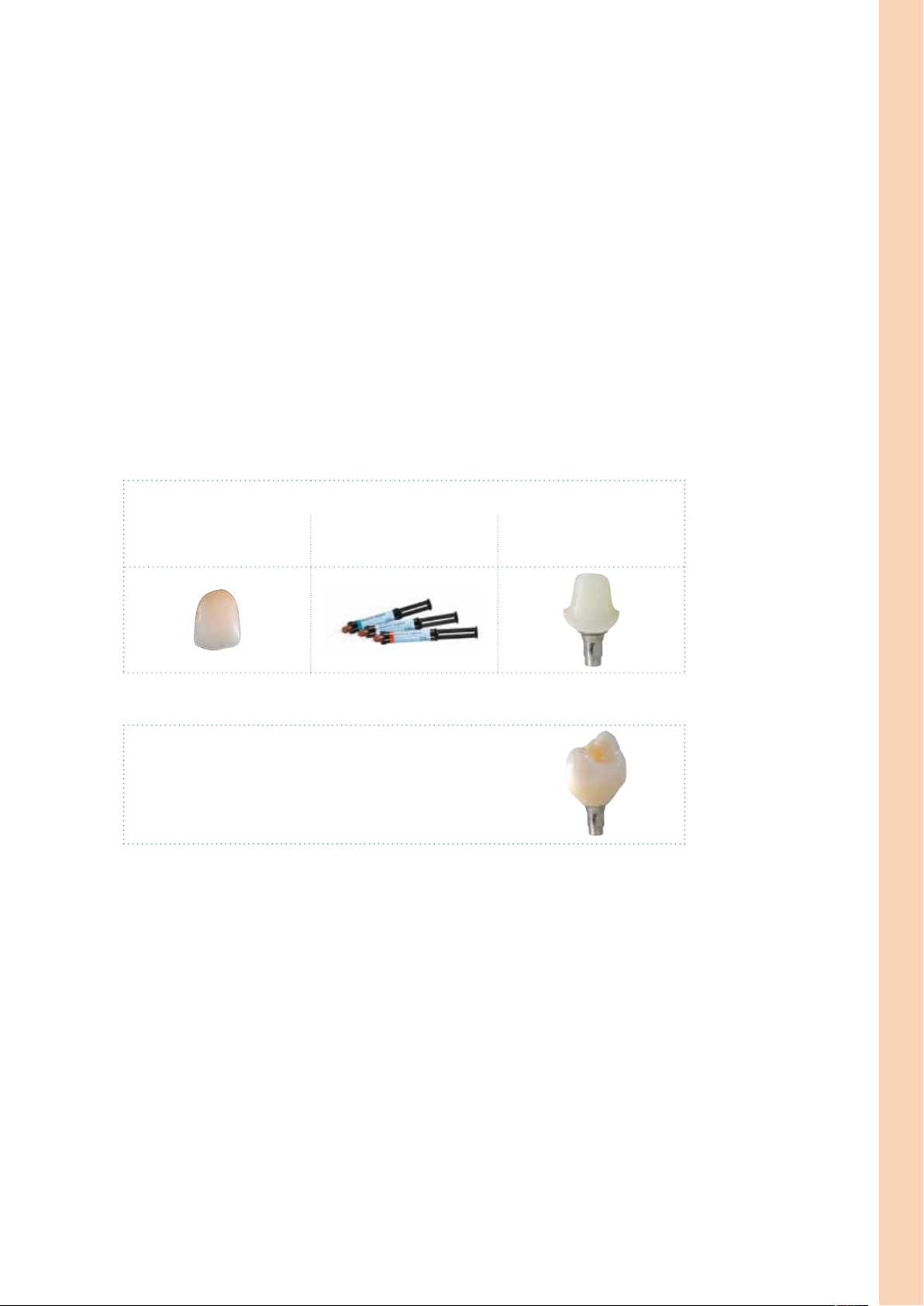
– Hybrid abutment and separate crown
– Hybrid abutment crown
Both solutions show outstanding function, efficiency and esthetics. The durable bond to the Ti base is achieved by means of the self-curing
Multilink Implant luting composite.
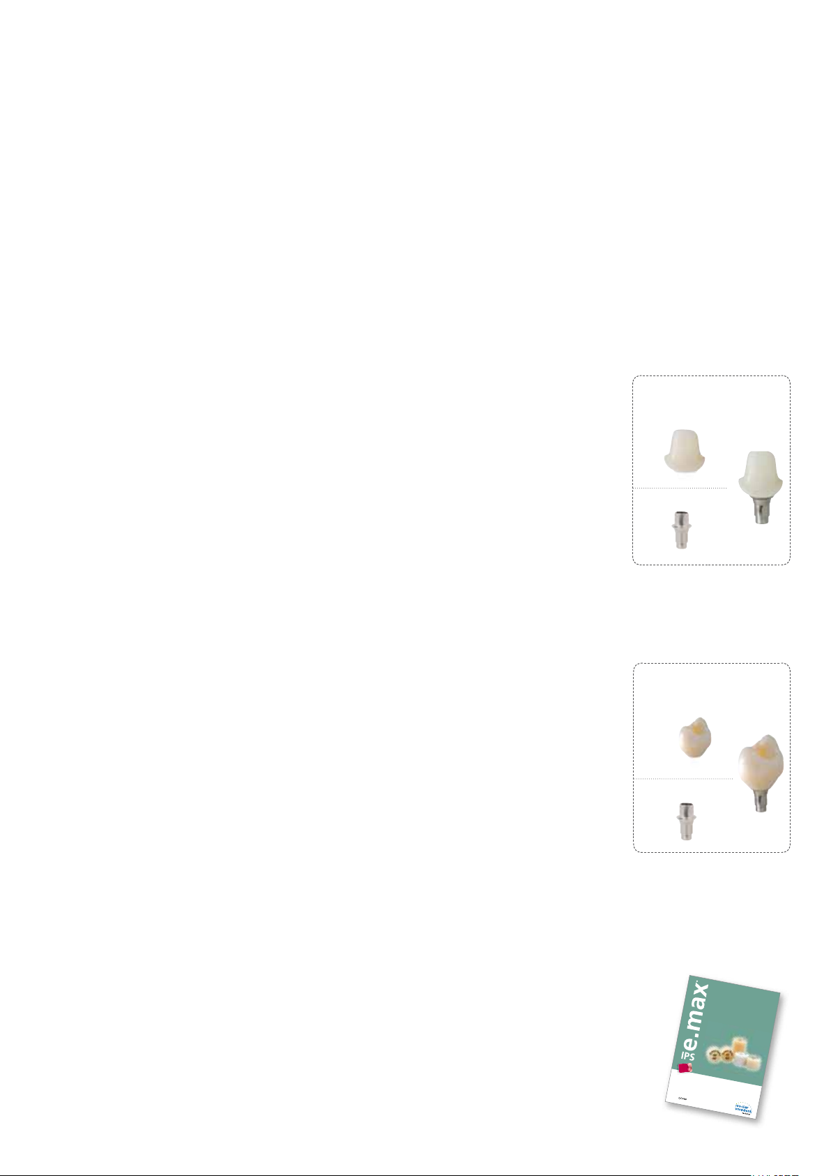
Hybrid abutment
The hybrid abutment is an individually pressed LS2 abutment which is luted to the Ti base. The shape,
emergence profile and esthetic properties of this abutment can be ideally adjusted to the clinical
situation.
Individual esthetics
Given the lifelike appearance of LS2 glass-ceramics, the esthetic possibilities are virtually limitless,
particularly in the anterior region. Due to the individual characterization, a lifelike appearance is
achieved near the root and the transition area to the crown. With the preparation margin of the crown
located on the gingival level, the geometry of the hybrid abutments allows for an easy integration of
the restoration. Excess cementation material is therefore easily removed.
Hybrid abutment
IPS e.max Press LS
AbutmentBase
Ti base
2
Flexibility due to laboratory fabrication
The pressed LS2 abutment is extraorally luted to a Ti base with Multilink Implant, then screwed into
place in the oral cavity and finally provided with a permanent IPS e.max crown. As the hybrid abutment
is conveniently fabricated in the lab, the process is time-saving and flexible.
Hybrid abutment crown
Hybrid abutment crowns are characterized by combining abutment and monolithic crown in one piece.
This is an efficient two-in-one solution made of lithium disilicate (LS2), which is directly luted to a Ti base.
Efficient fabrication due to two-in-one approach
LS2 glass-ceramics provide for strength, durability and efficiency, particularly in the posterior area.
Moreover, the material offers well-known esthetic properties allowing restorations to be simply
characterized with IPS e.max Ceram stains.
Luted extraorally, screwed in intraorally – for improved flexibility
The monolithically pressed hybrid abutment crown is reliably luted to the Ti base by means of Multilink
Implant. Then, the restoration is screwed onto the implant – in one piece. Thus, the bothersome task of
excess cement removal is a thing of the past. Subsequently, the screw access channel is sealed with a
composite material (e.g. Tetric EvoCeram®). If required, the screw can be accessed at any time, which
affords the dental team clincial flexibility.
New possibilities for economically efficient restorations
IPS e.max Press hybrid abutment crowns are a new, economically attractive alternative to conventional
implant-supported restorations, particularly for the posterior area, where strength, durability and convenient clinical handling matter.
Hybrid abutment crown
IPS e.max Press LS
Abutment
Ti base
Base
2
Note regarding the Instructions for Use:
The present Instructions for Use deal only with IPS e.max Press Abutment Solutions and represent a
supplement to the existing IPS e.max Press Instructions for Use. The IPS e.max Press Instructions for Use
contain more detailed descriptions of the material (e.g. ingot concept) and the entire indication range.
In case you do not have the IPS e.max Press Instructions for Use, you can order them from your sales
representative or simply download it from www.ivoclarvivadent.com.
3
Page 4
Material
Uses
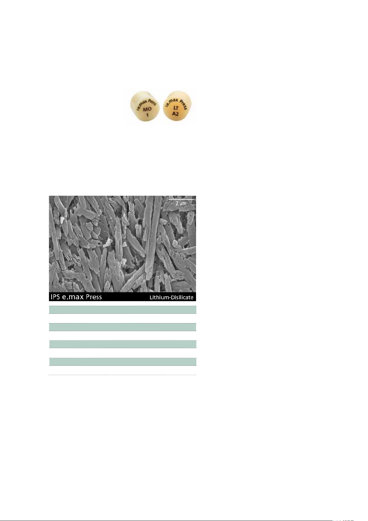
Press ceramic
IPS e.max Press are lithium disilicate glass-ceramic (LS2) ingots for
the press technology. The industrial
production process creates absolutely homogeneous ingots in different translucency levels. For IPS e.max Press Abutment Solutions,
ingots from the exisitng range of products are used.
The ingots feature a strength of 400 MPa and are thus the pressed
ceramic ingots with the highest strength. They are pressed in Ivoclar
Vivadent press furnaces to produce objects with outstanding accuracy
of fit. The pressed, tooth-coloured, highly esthetic restorations are
completed with IPS e.max Ceram.
CTE (100–400°C) [10-6/K] 10.2
CTE (100-500°C) [10-6/K] 10.5
Flexural strength (biaxial) [MPa]* 400
Fracture toughness [MPa m
Modulus of elasticity [GPa] 95
Vickers hardness [MPa] 5800
Chem. solubility [µg/cm2]* 40
Pressing temperature [°C] 915–920
*according to ISO 6872
0.5
] 2.75
Indications
– Hybrid abutments for anterior and posterior single-tooth
restorations
– Hybrid abutment crowns for anterior and posterior restorations
Contraindications
– Use of Ti bases which do not fulfil the geometry requirements.
– Failure to observe the requirements stipulated by the implant
manufacturer for using the selected implant type (diameter and
length of the implant must be approved for the respective position
in the jaw by the implant manufacturer).
– Bruxism
– Failure to observe the permissible maximum and minimum ceramic
wall thicknesses.
– All uses not stated as indications are contraindicated.
Important processing restrictions
Failure to observe the following restrictions may compromise the
results achieved with IPS e.max Press:
– If hybrid abutment crowns are fabricated, the opening of the
screw channel must not be located in the area of contact points
and areas with masticatory function. If this is not possible, a
hybrid abutment with a separate crown would be preferred.
– No extension units; only single-tooth restorations
– Layering with a veneering ceramic other than IPS e.max Ceram
– Pressing of two or more IPS e.max Press ingots in one investment
ring
– Pressing of IPS e.max Press in the IPS Investment System 300 g
– Use of a luting composite other than Multilink® Implant to lute
IPS e.max Press to the Ti base
– Temporary cementation of the crown on the hybrid abutment.
– Failure to observe the manufacturer's instructions regarding the
processing of the Ti base.
Side effects
If the patient is known to be allergic to any of the components,
IPS e.max Press Abutment Solutions should not be used.
Ti base
For IPS e.max Press Abutment Solutions, customary Ti bases made of
titanium or titanium alloys are used.
Please observe the instructions for use and processing of the manufacturer of the Ti bases used.
4
Page 5

Composition
IPS e.max Press ingots and accessories required in conjunction with
IPS e.max Press Abutment Solutions consist of the following main
components:
– IPS e.max Press ingots
Components: SiO2
Additional components: Li2O, K2O, MgO, ZnO, Al2O3, P2O5 and
other oxides
– IPS Alox Plunger
Components: Al
– IPS Alox Plunger Separator
Components: Boron nitride
– IPS e.max Press Invex Liquid
Components: Hydrofluoric acid and sulphuric acid in water
– IPS PressVEST Powder
Components: SiO2, MgO and NH4H2PO4
– IPS PressVEST Liquid
Components: Colloidal silicic acid in water
2O3
Warning
– Do not inhale ceramic dust during finishing – use exhaust air
discharge and mouth protection.
– IPS Ceramic Etching Gel contains hydrofluoric acid. Contact with
skin, eyes and clothing must be prevented at all costs, since the
material is extremely toxic and corrosive. The etching gel is intended
for professional use only and must not be applied intraorally
(inside the mouth).
– IPS PressVEST Speed Powder
Components: SiO2, MgO and NH4H2PO4
– IPS PressVEST Speed Liquid
Components: Colloidal silicic acid in water
– IPS Object Fix Flow
Components: Oxides, water, thickening agent
– IPS Ceramic Etching Gel
Components: Hydrofluoric acid (approx. 5%)
– Virtual Extra Light Body Fast Set
Components: Addition-reaction silicone, vinyl polysiloxane,
methylhydrogensiloxane, organoplatinic complex, silica
– Monobond Plus
Components: Alcohol solution of silane methacrylate, phosphoric
acid methacrylate and sulphide methacrylate
– Multilink Implant
Components: Dimethacrylate, HEMA, barium glass, ytterbium tri-
fluoride, spheroid mixed oxide
5
Page 6
®
e.max
IPS
Press Abutment Solutions
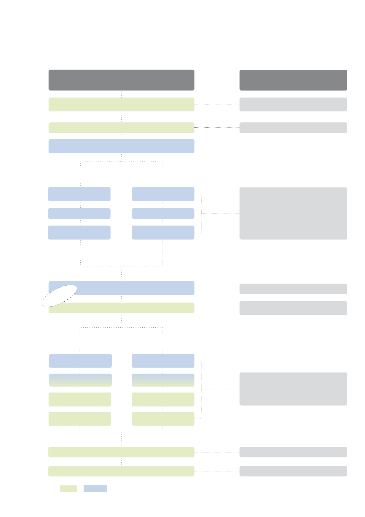
Treatment/Fabrication Process
Implantation, healing phase,
Shade determination, impression-taking
Hybrid
abutment
Contouring
and Investing
Pressing
Characterization, glaze
Optional: Polishing
Crown made of
IPS e.max Press
Working steps
gingiva shaping
Model fabrication,
selection of Ti base
Hybrid
abutment crown
Contouring
and investing
Pressing
Characterization, glaze
Ivoclar Vivadent
All the products
Cervitec Plus, Cervitec Liquid,
Telio system
OptraGate, Virtual
IPS Investment Ring System 100g, 200g
IPS PressVEST, IPS PressVEST Speed
IPS e.max Press
Programat EP 3000, EP5000
IPS Alox Plunger
IPS Alox Plunger Separator
IPS e.max Ceram
Programat P300, P500, P700
Temporarily securing
pressed object – Ti base
Optional
Hybrid
abutment
Cementing
pressed object – Ti base
Preparing for
intraoral cementation
Screwing in the hybrid abut-
ment intraorally
Cementation
IPS e.max Press crown
Checking the articulation/occlusion
Clinical try-in
pressed object – Ti base
intraoral cementation
Screwing in the hybrid abut-
ment crown intraorally
Virtual Extra Light Body Fast Set
OptraGate, Virtual Extra Light Body Fast Set,
Liquid Strip
Hybrid
abutment crown
Cementing
Preparing for
IPS Ceramic Etching Gel, Monobond Plus,
Multilink Implant, Liquid Strip,
Tetric EvoCeram, bluephase
Sealing
the screw channel
OptraFine, OptraPol, AstroPol
Practice
Laboratory
Recall
Implant Care
6
The range of available products may vary from country to country.
Page 7
Shade – tooth shade, preparation shade/abutment shade
Optimum integration in the oral cavity of the patient is the prerequisite for a true-to-nature all-ceramic
restoration. To achieve this, the following guidelines and notes must be observed by both the dentist and
the laboratory.
With IPS e.max Press Abutment Solutions, you can imitate not only the clinical crown of a natural tooth,
but also a part of the "root". By defining/determining the "root shade" you can adjust the shade of the
IPS e.max Press Abutment Solution restoration accordingly. This allows you to achieve a highly esthetic
implant-supported restoration which retains its lifelike appearance also in the case of gingiva recession.
Hybrid abutment and separate crown
Restoration shade
(pressed ceramic LS
characterization)
,
2
(crown on hybrid abutment)
Shade luting material
Shade hybrid abutment
(Ti base, luting material, pressed
ceramic LS2)
Hybrid abutment crown
Shade hybrid abumtent crown
(Ti base, luting material, pressed ceramic LS
, characterizations)
2
Please refer to the table on page 52 for the selection of the suitable IPS e.max Press ingot.
Application procedure – Fabrication Hybrid Abutment and Hybrid Abutment Crown
7
Page 8
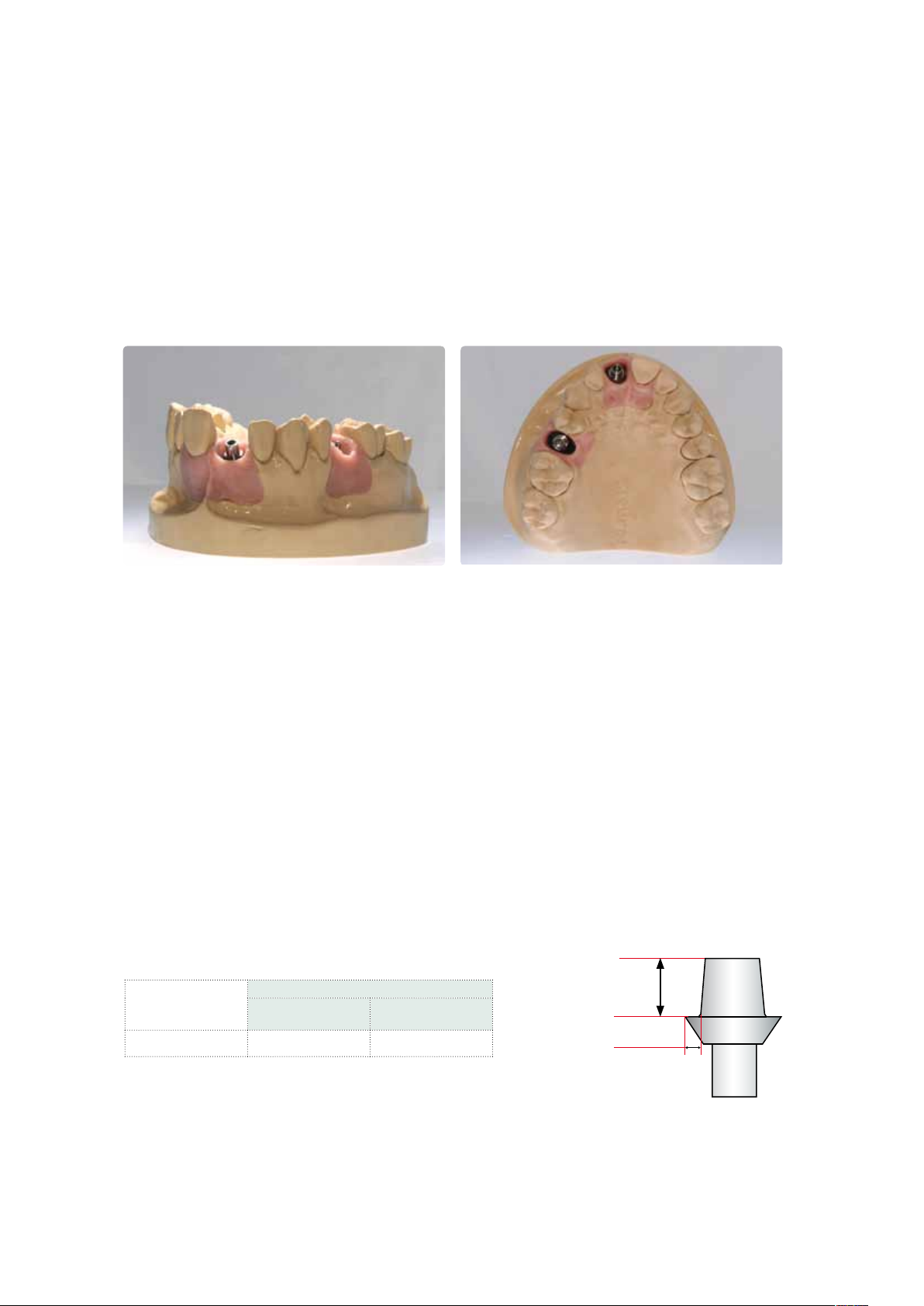
Model preparation
For the fabrication of an IPS e.max Press Abutment Solutions restoration, a model with gingiva mask is fabricated.
– Select the suitable model analog according to the implant system used.
– Fabricate a model with gingiva mask.
Prepared model with gingiva mask
Selecting a Ti base
The following paragraphs outline the selection criteria for a suitable Ti base. As a general rule, the instructions of the
respective manufacturer regarding the use of the Ti base have to be observed.
– Only bases consisting of Ti or Ti alloys must be used.
– Select a Ti base with a size that matches the clinical situation and the chosen implant system. The geometry
requirements must be observed.
– The rotation lock must be designed in such a way that stress concentrations on the pressed object are avoided.
– Ti bases with undercuts, e.g. retention grooves, are suitable to some extent.
– Check the available space for the pressed object taking the geometry of the Ti base into account on the model (e.g.
silicone key).
– Observe the instructions of the manufacturer when modifying the Ti base.
Height H
Minimum dimensions
Height H
(bonding surface)
Ti
Shoulder width S
Ti base HTi min. 4.0 mm STi min. 0.6 mm
Ti
Ti
(luted area)
Marginal shoulder
width S
Ti
8
Page 9
Layer thicknesses of the ceramic components
Observing the geometry requirements of the pressed objects made of IPS e.max Press material is the key to success for a
durable restoration. The more attention given to the design, the better the final results and the clinical success will turn out
to be. The following basic guidelines have to be observed:
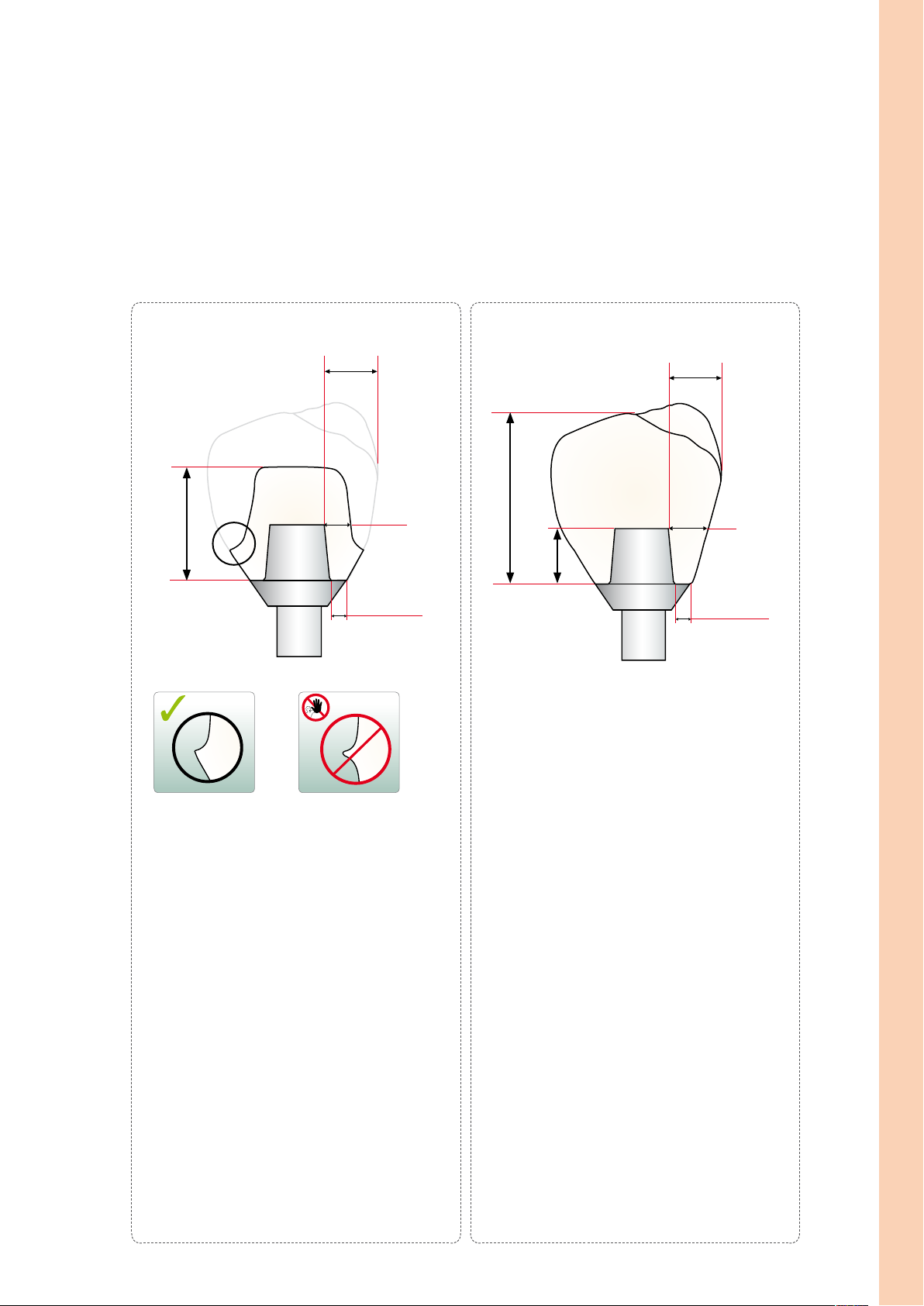
Hybrid abutment
Width abutment crown B
A
Height H
Wall thickness W
Marginal
shoulder width S
AK
AK
Height H
A
A
Hybrid abutment crown
Height
Ti base
Width abutment crown B
Wall thickness W
Marginal
shoulder width S
AK
AK
Application procedure – Fabrication Hybrid Abutment and Hybrid Abutment Crown
A
– The marginal shoulder width SA must be at least
0.6 mm.
– Create an emergence profile with a right angle at
the transition to the crown (see picture).
– The wall thickness WA must be at least 0.5 mm.
– The height HA must not exceed twice the height of
the Ti base HTi.
– The hybrid abutment should be designed in a simi-
lar way as a prepared natural tooth:
– Circular epi-/supragingival shoulder with rounded
inner edges or a chamfer.
– In order for the crown to be cemented to the
hybrid abutment using a conventional/self-
adhesive cementation protocol, retentive surfaces
and a sufficient "preparation height" must be
observed.
– The width BAK of the crown is limited to 6.0 mm
from the axial height of contour to the screw
channel of the hybrid abutment.
– The marginal shoulder width S
must be at least
A
0.6 mm.
– The wall thickness WAK must be larger than 1.5 mm
for the entire circumference.
– The opening of the screw channel must not be
located in the contact point areas or areas with a
masticatory function. If this is not possible, a hybrid
abutment with a separate crown should be
preferred.
– The width of the hybrid abutment crown BAK is
limited to 6.0 mm from the axial height of contour
to the screw channel.
– The height HAK must not exceed twice the height of
the Ti base by more than 2 mm.
9
Page 10
Modeling
Fabrication of a resin coping
To prepare the wax-up, a resin coping is prepared if both hybrid abutments and hybrid abutment crowns
are fabricated. Please observe the following procedure:
– Check the implant position and inclination with regard to the position of the screw channel.
– Screw the Ti base onto the model analog with the corresponding screw.
– Tip: Make sure that an additional model analog is available as this will facilitate some steps.
– Clean the Ti base with a steam cleaner.
– Insert a pin with the same diameter as the screw channel to "seal" and "extend" the screw channel.
– Do not apply die spacer.
– Isolate the Ti base and the pin with a thin application of separator. If too much separator is used, this
might result in uneven areas on the inner aspect of the pressed object.
– In order to achieve a sound fit and to facilitate the subsequent wax-up, a coping is first fabricated on
the Ti base with modelling resin. Design the coping in such a way that it can subsequently be completely covered with modelling wax. Please observe the instructions of the manufacturer regarding the
processing of modelling resin.
– Remove the Ti base from the model.
– Eliminate possible over-contoured areas of the resin coping at the transition area to the Ti base by
means of rubber polishers. Do not damage the Ti base.
– Remove the resin coping together with the pin from the T i base.
– Loosen and remove the pin by rotating the resin coping.
– Screw the Ti base onto the model analog again.
– Place the resin coping back on the Ti base and check the fit and dimension (e.g. silicone key). If
necessary, adjust the coping by means of rotary instruments.
Screw the Ti base onto the model analog with the corresponding screw. – Insert a pin with the same diameter as the screw channel to "seal" and "extend"
10
the screw channel.
Page 11
Isolate the Ti base and the pin with a thin application of separator.
Apply the modelling resin to the Ti base in increments.
Application procedure – Fabrication Hybrid Abutment and Hybrid Abutment Crown
Design the resin coping on the entire Ti base.
Loosen and remove the pin by rotating the resin coping.
Remove the resin coping together with the pin from the Ti base.
Eliminate possible over-contoured areas of the resin coping at the transition area to
the Ti base by means of rubber polishers.
Place the resin coping back on the Ti base and check the fit and dimension (e.g. silicone key). If necessary, adjust the coping by means of rotary instruments.
Design the coping in such a way that it can subsequently be covered with modelling wax.
11
Page 12
Wax-up
Please observe the following notes with regard to modelling:
– Observe the stipulated layer thicknesses.
– Create an accurate model of the restoration, particularly at the transition area to the Ti base.
– Do not over-contour the margins, since this would require time-consuming and risky fitting procedures after pressing.
– Use an organic wax for modelling to ensure that it burns out without leaving residue in the investment ring.
Procedure for hybrid abutments
– Before creating the wax object, re-insert the isolated pin into the screw channel.
– Design the emergence profile by flooding the area between the gingiva mask and the resin coping with wax.
– Contour the hybrid abutment to a reduced tooth shape. The hybrid abutment should be designed in such a way that the
required layer thicknesses are met in the crown that is fabricated. Check by means of the silicone key and in relation to
the opposing dentition.
– Determine the crown margins in relation to the gingiva level.
– Design a chamfer on which the crown is subsequently seated.
– Remove the object together with the Ti base from the model and check the emergence profile. If necessary, make
adjustments.
– Check the transition to the Ti base and remove excess wax.
– Check the required minimum thicknesses (page 9) prior to attaching the sprue.
Design the emergence profile by flooding the area between the gingiva mask and the
resin coping with wax.
Check the dimensions by means of the silicone key and in relation to the opposing
dentition.
Design the hybrid abutment with a reduced tooth shape and determine the crown
Remove the object together with the Ti base from the model and check the emergence
profile. If necessary, make adjustments. Check the transition to the Ti base and
12
margin in relation to the gingiva level.
thoroughly remove excess wax.
Page 13
Procedure for hybrid abutment crowns:
– If required, re-insert the isolated pin into the screw channel before creating the wax object.
– Design the emergence profile by flooding the area between the gingiva mask and the resin coping with wax.
– Design the abutment crown to full contour according to functional and esthetic criteria. Check in relation to the
opposing dentition.
– Make sure to take a slightly reduced occlusal relief into consideration during the wax-up, since the application of the
Stains and Glaze results in a slight increase in vertical dimensions.
– Remove the object together with the Ti base from the model and check the emergence profile. If necessary, make
adjustments.
– Check the transition to the Ti base and remove possible excess wax.
– Check the required thicknesses (page 9) prior to attaching the sprues.
Application procedure – Fabrication Hybrid Abutment and Hybrid Abutment Crown
Design the emergence profile by flooding the area between the gingiva mask and the
resin coping with wax. If necessary, re-insert the pin prior to modelling.
Design the abutment crown to full contour according to functional and esthetic
criteria. Check the object in relation to the opposing dentition.
13
Page 14
Sprueing
Please observe the following notes when attaching the sprues to the abutment or the abutment crown:
– Depending on the number and size of the objects to be invested, either the 100 g or 200 g IPS Investment Ring System
is selected. Before sprueing, weigh the ring base and record the weight (seal the opening of the ring base with wax).
Please note that the mixing ratio of the investment material is different for the various restoration types (e.g. inlays,
crowns, abutments).
– Use a 2.5 mm wax wire for sprueing.
– For abutments, the sprue is attached to an axial surface.
– For abutment crowns, the sprue is attached to a cusp.
– Align the wax wire as parallel as possible to the screw channel in order to prevent the investment material
from fracturing in the screw channel.
– The maximum length (object + sprue) of 16 mm must not be exceeded.
– Place the object on the investment ring base in such a way that the screw channel is parallel to the outer wall of the
investment ring. As a result, the investment material can subsequently be filled evenly and in a controlled manner. The
objects could be placed in a tilted position on the investment ring base, but this may lead to difficulties during investing
(e.g. bubbles in the screw channel).
– Observe a distance of at least 10 mm between the object and the silicone ring.
– If only one object is invested and pressed in an EP500 furnace, a second short (blind) sprue must be placed. This ensures
that the switch-off function of the furnace works properly at the end of the pressing procedure.
ø 2.5 mm ø 2.5 mm
Attach the sprue to a circular area of the abutment model and as parallel as possible
to the screw channel. Use a 2.5 mm wax wire.
Attach the sprue to an oral cusp of the abutment crown and as parallel as possible to
the screw channel. Use a 2.5 mm wax wire.
Place the object on the investment ring base in such a way that the screw channel is parallel to the outer wall of the investment ring.
Furthermore, this reduces the risk of the investment material breaking in the screw channel while the ceramic material is pressed.
As a result, the investment material can subsequently be filled evenly and in a controlled manner.
14
Page 15
Investing
Investing is carried out with either IPS PressVEST or IPS PressVEST Speed. The corresponding IPS Silicone Ring with the
matching ring gauge is used for investment.
Determine the weight of the object before investing.
– Position the wax objects on the ring base and attach them with wax and weigh.
– The difference between the empty and the loaded ring base is the definitive wax weight.
Small Ingot Large Ingot (L)
Wax weight up to max. 0.75 g up to max. 2 g
Investment Ring System 100 g and 200 g only 200 g
Please refer to the Instructions for Use of the corresponding investment material regarding the detailed processing
parameters. The following basic procedure is recommended:
– Do not use a debubblizer on the wax objects.
– Carefully place the IPS Silicone Ring on the ring base without damaging the objects. The silicone ring must sit flush on
the ring base.
– The processing temperature of the investment material is 18– max. 23 °C / 64 °F – max. 73 °F. Higher or lower
processing temperatures substantially affect the setting behaviour.
– Mix the investment material. Note: The investment material contains quartz powder. Therefore, avoid the inhalation of
dust.
– Important: Pour the investment material slowly into the investment ring, so that the material continuously
fills the screw channel. If the material does not sufficiently fill the screw channel, use an instrument to
carefully apply additional investment material to the screw channel from the top.
– Carefully fill the investment ring with investment material up to the marking on the silicone ring and position the ring
gauge with a hinged movement.
– Allow the investment ring to set without manipulating it.
– To prevent crystallization of the IPS PressVEST investment material, the invested ring must be processed within 24 hours.
– If IPS PressVest Speed is used, make sure that the investment ring is placed in the preheating furnace after a setting time
of at least 30 and maximum 45 minutes.
Application procedure – Fabrication Hybrid Abutment and Hybrid Abutment Crown
Investment material: Liquid concentration and quantity
IPS PressVEST IPS PressVEST Speed
Indication
Investment Ring
Liquid : dist. water
200 g
Investment Ring
Liquid : dist. water
100 g
Investment Ring
Liquid : dist. water
200 g
Investment Ring
Liquid : dist. water
100 g
IPS e.max Press
Hybrid abutment
Hybrid abutment crown
Mixing time
(under vacuum at approx. 350 rpm)
Liquid concentration: The data contained in the table are approximative values. Depending on the geometry of the Ti
base and the materials used for the wax-up, these values may be individually changed. However, the concentrated Liquid
content must not be lower than 50% in relation to distilled water.
Important: The total quantity of liquid (Liquid + dist. water) must not be altered.
16 ml : 6 ml 32 ml : 12 ml 20 ml : 7 ml 40 ml : 14 ml
60 seconds
If a high-speed mixer is used, the mixing time under
2.5 minutes
vacuum has to be reduced.
15
Page 16
Correctly sprued abutment (left) and abutment crown (right). The screw channel is in a
vertical position and parallel with the wall of the investment ring.
Continue to carefully fill the investment ring up to the marking and position the ring gauge with a hinged movement.
Pour the investment material slowly into the investment ring, so that the material can
continuously fill the screw channel.
16
Page 17
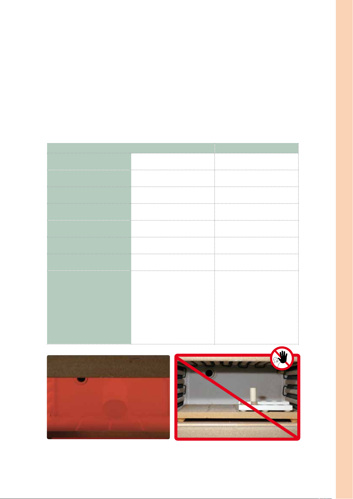
Preheating
After the stipulated setting time of the respective investment material (IPS PressVEST or IPS PressVEST Speed), the investment ring is prepared for preheating as follows:
– Remove the ring gauge with a turning movement.
– Carefully push the investment ring out of the IPS Silicone Ring.
– Remove the ring base with a turning movement.
– Remove rough spots on the bottom surface of the investment ring with a plaster knife. Check the 90° angle. Investment
material residue must not enter the sprues. Blow into the sprues if necessary.
– If several investment rings are preheated together, mark them accordingly.
IPS PressVEST IPS PressVEST Speed
Setting time min. 60 min, max. 24 hrs min. 30 min, max. 45 min
Temperature of the preheating furnace
when placing the investment ring
Position of the investment ring in the
preheating furnace
Final temperature for preheating the
investment ring
Holding time of the investment ring at
final temperature
IPS e.max Press ingots no preheating no preheating
IPS Alox Plunger no preheating no preheating
Important If several Speed investments are to be
Towards the rear wall, tipped with the
Room temperature
opening facing down
850 °C / 1562 °F 850 °C / 1562 °F
min. 60 min
850 °C / 1562 °F; switch on the
preheating furnace in time.
Towards the rear wall, tipped with the
opening facing down
100 g investment ring – min. 45 min
200 g investment ring – min. 60 min
conducted, they should be invested
consecutively and placed into the pre-
heating furnace at an interval of
approx. 20 minutes. Make sure that
the furnace temperature does not
drop too much when placing the
investment rings into the preheating
furnace. The stipulated holding time
counts from the point when the pre-
heating temperature has been reached
again.
Application procedure – Fabrication Hybrid Abutment and Hybrid Abutment Crown
Towards the rear wall, tipped with the opening facing down Do not preheat the IPS e.max Press ingot and Alox Plunger.
In order to ensure smooth working procedures in the laboratory on a daily basis, impeccable functioning of the infrastructure, particularly the preheating furnaces, is essential. This includes their maintenance, cleaning with a vacuum cleaner in a
cool state as well as regular checks of the temperature controls and heating elements, etc., by the manufacturer.
17
Page 18

Pressing
Carry out the following preparatory steps for pressing before the preheating cycle for the investment ring has been
completed:
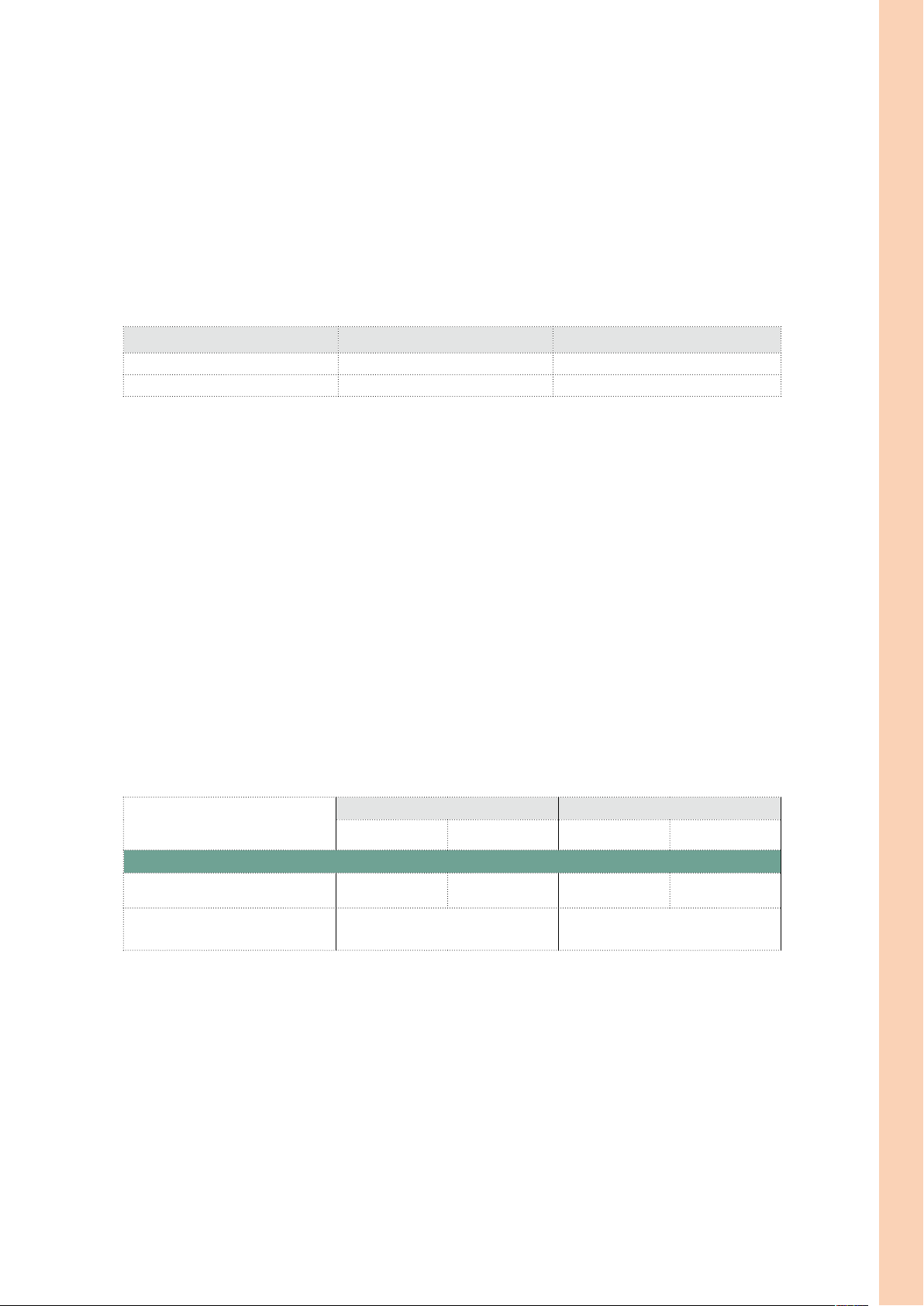
– Provide a cold IPS Alox Plunger and a cold IPS e.max Press ingot in the desired shade (please refer to the material
selection table on page 52).
– Dip the cold IPS Alox Plunger into the opening of the IPS Alox Plunger Separator and keep it ready for use.
– Turn on the press furnace (e.g. Programat EP 5000) in time so that the self-test and preheating phase are completed.
– Select the press program for IPS e.max Press and the desired investment ring size.
Remove the investment ring from the preheating furnace immediately after completion of the preheating cycle. This step
may take max. 30 seconds to prevent the investment ring from cooling down too much.
– Place the cold IPS e.max Press ingot into the hot investment ring.
– Insert the ingots in the investment ring with the non-imprinted side facing down. The imprinted side faces up to check
the ingot shade.
– Place the side of the cold IPS Alox Plunger which has been coated with Separator into the hot investment ring.
– Use the investment ring tongs to place the loaded investment ring in the centre of the hot press furnace.
– The selected press program is started by pressing START.
After the end of the press cycle (optical and/or acoustic signal) proceed as follows:
– Remove the investment ring from the press furnace using the investment ring tongs immediately after pressing.
– Place the investment ring on a cooling grid to cool in a place protected from draft.
– Do not speed up cooling, e.g. by blasting with compressed air.
100 g Investment Ring 200 g Investment Ring
1 small ingot
1 small ingot
IPS e.max Press ingots cold ingot cold ingot
IPS Alox Plunger cold plunger cold plunger
IPS Alox Plunger Separator
Ingots: select one large or one small ingot according to the determined wax weight!
✓ ✓
or
1 large ingot
Provide a cold isolated IPS Alox Plunger and a cold IPS e.max Press ingot in the
desired shade.
Place the cold IPS e.max Press ingot into the hot investment ring with the imprinted
18
side facing up.
Page 19

Then, place the side of the IPS Alox Plunger which has been coated with Separator
into the hot investment ring.
Place the hot and loaded investment ring in the centre of the hot press furnace using
the IPS Investment Ring Tongs.
Application procedure – Fabrication Hybrid Abutment and Hybrid Abutment Crown
Press START to start the selected program. Once the press program is completed, place the hot investment ring on the cooling
grid using the Investment Ring Tongs and allow it to cool to room temperature.
Press parameters for IPS e.max Press
Programat EP 3000
Select the press program in accordance with the selected ingot to be pressed
and the investment ring size used.
The press parameters for HO, MO, LT and HT are integrated
starting with software V 6.1.
Programat EP 5000
Select the press program in accordance with the selected ingot to be pressed
and the investment ring size used.
The press parameters for HO, MO, LT and HT are integrated starting
with software V 6.1.
The press parameters for older-generation Ivoclar Vivadent press furnaces
are listed on page 53 under Press Parameters.
19
Page 20

Divesting
After cooling to room temperature (approximately 60 minutes), the investment ring may show cracks, which developed
during the cooling phase (immediately around the Alox plunger). This is the result of the different CTEs of the various
materials (Alox Plunger, investment material and press ingot) and does not compromise the press results.
Divest the investment ring as follows:
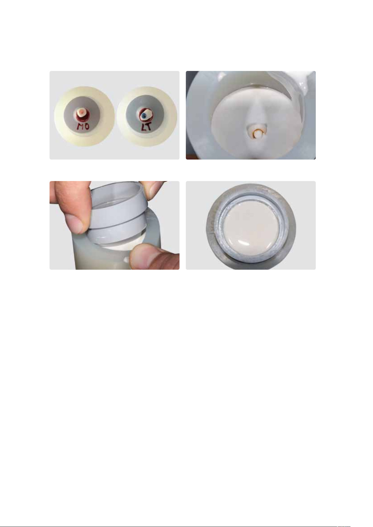
– Mark the length of the Alox Plunger on the cooled investment ring.
– Separate the investment ring using a separating disc. This predetermined breaking
point enables reliable separation of the Alox Plunger and the ceramic material.
– Break the investment ring at the predetermined breaking point using a plaster knife.
– Always use polishing beads to divest the pressed objects (rough and fine divestment).
Do not use Al2O3.
– Rough divestment is carried out with polishing beads at 4 bar (58 psi) pressure.
– Fine divestment is carried out with polishing beads at 2 bar (29 psi) pressure.
– Observe the blasting direction and distance to prevent damage to the object margins
during divestment.
– Same as the outer surfaces, thoroughly blast the screw channel with polishing beads
at 2 bar (29 psi) pressure.
– Remove possible ceramic residue from the Alox Plunger with type 100 Al2O3.
Mark the length of the Alox Plunger.
Separate the investment ring using a separating disc and break it at the predetermined breaking point.
Tip
Pull out the plunger with pliers from the separated segment using a rotating movement.
This also removes any possible ceramic residue from the Alox plunger.
20
Page 21

Rough divesting with polishing beads at 4 bar (58 psi) pressure until the object
becomes visible.
Fine divestment of the abutment is carried out with polishing beads
at 2 bar (29 psi) pressure.
Application procedure – Fabrication Hybrid Abutment and Hybrid Abutment Crown
Fine divestment of the abutment crown is carried out with polishing beads at 2 bar
(29 psi) pressure.
Completely divested IPS e.max Press objects.
21
Page 22

Removing the reaction layer
After fine divestment, the reaction layer formed during the press procedure is removed using IPS e.max Press Invex Liquid.
The procedure is carried out as follows:
– Pour the Invex Liquid into a plastic cup.
– Immerse the pressed object in the Invex Liquid and clean in an ultrasonic cleaner for at least 10 min and at most 30 min.
Make sure that the objects are completely covered with Invex Liquid.
– Use the sieve insert to remove the restoration from the Invex Liquid and clean the object under running water and blow
dry.
– Carefully remove the white reaction layer with type 100 Al2O3 at max. 1–2 bar (15–29 psi) pressure.
– Make sure that the reaction layer is completely removed, both from the screw channel and the outer side of the object
(repeat the procedure, if necessary).
– If the reaction layer is not completely removed, problems may occur in the further course of the fabrication process.
– Replace the IPS e.max Invex Liquid after 20 applications or after sedimentation of the Liquid.
To remove the reaction layer, immerse the pressed objects in IPS e.max Press Invex ... ... and place in an ultrasonic cleaner for at least 10 and at most 30 minutes.
Using Al
and a pressure of at most 1–2 bar (15–29 psi) pressure, carefully remove
2O3
the reaction layer from the outer side ...
... and the screw channel.
Warning
– The Invex Liquid contains < 1% hydrofluoric acid.
– It is harmful when inhaled, swallowed and when it comes into contact with the skin. Furthermore, it is corrosive.
– Keep the container tightly sealed and store it in a well-ventilated place (acid cabinet).
– If the material comes into contact with the eyes, immediately rinse with copious amounts of water and see an ophthalmologist
immediately.
– In case of accidental contact with skin, immediately wash with plenty of water.
– Use suitable protective clothing, gloves and goggles when working.
– In case of an accident or physical discomfort, see a physician immediately, and take the Invex label with you, if possible.
Disposal
– Neutralize the Invex Liquid before disposal!
– Use the IPS Ceramic Neutralization Powder to neutralize the Invex Liquid.
– For 50 ml Invex Liquid, approx. 3–4 g of IPS Ceramic Neutralization Powder are required.
– Note: strong foam development during neutralization.
– Carefully add the neutralization powder to the Invex Liquid in small portions until foam is no longer formed; then allow a
reaction time of 5 minutes.
– If larger quantities are disposed of, check the liquid with litmus paper (must show an alkaline reaction).
– After the reaction time, pour the neutralized solution into the sink, flushing it with running water.
22
Page 23

Finishing
It is of critical importance to use the correct grinding instruments for finishing and adjusting high-strength glass-ceramics
(please refer to the Ivoclar Vivadent Flow Chart "Recommended grinding instruments for glass-ceramics"). If unsuitable
grinding instruments are used, chipping of the edges and local overheating may occur.
Observe the following procedure for finishing IPS e.max Press restorations:
– Adjustment by grinding of pressed IPS e.max Press restorations should be kept to a minimum.
– Overheating of the ceramic must be avoided. Low speed and light pressure is recommended.
– Make sure that the minimum thicknesses are maintained even after the minor adjustments.
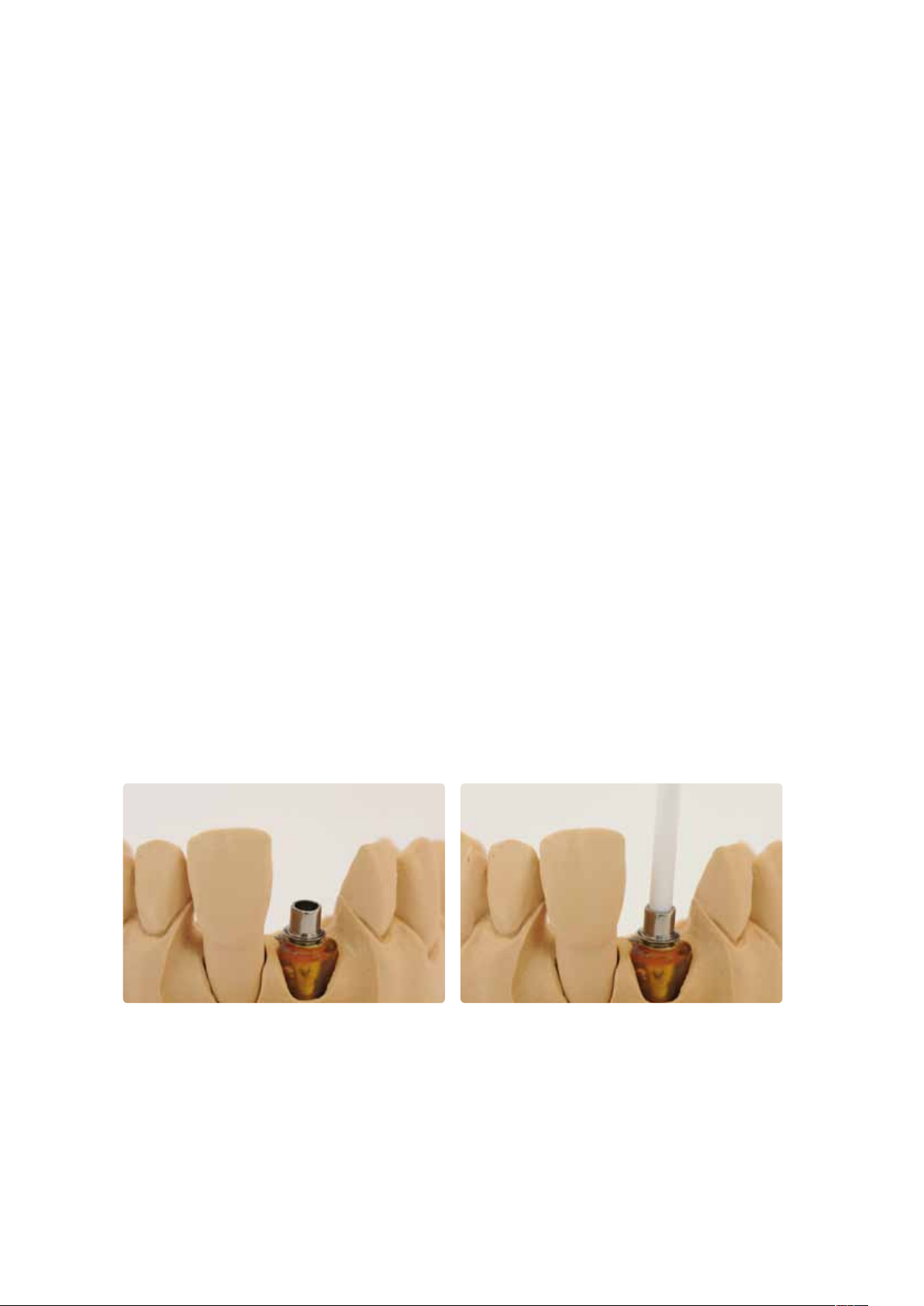
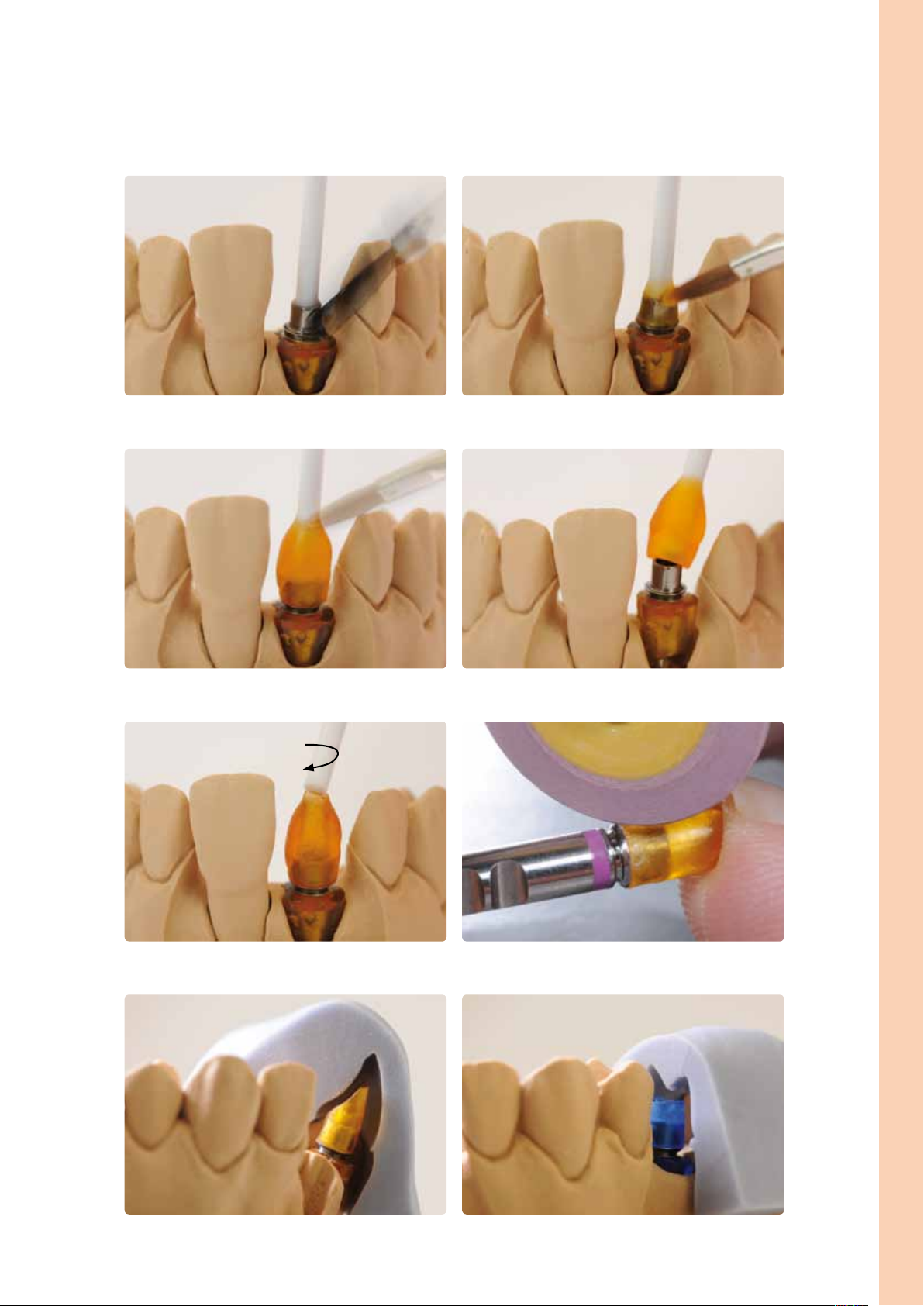
Fitting to the Ti base
The fit of the abutment or abutment crown is checked on the Ti base before the sprue is separated.
– Before the object is fitted, the inner aspect of the object (screw channel) is checked for bubbles in the ceramic. If
required, the bubbles are removed with suitable instruments.
– Carefully position the abutment or abutment crown on the Ti base. Note: Apply only light pressure to secure the pressed
object on the Ti base in order to prevent chipping of the ceramic. Observe the position of the rotation lock.
– Possible rough spots interfering with the fit of the pressed object on the Ti base cause greyish-black markings on the
screw channel. Carefully remove such markings with suitable grinding instruments. The diameter of the grinding
instrument must be smaller than that of the screw channel. As an alternative to marking the rough spots, an occlusion
spray can also be used.
– Carefully remove possible rough spots until an optimum fit between the Ti base and the pressed object is achieved.
Repeat the procedure, if required.
Application procedure – Fabrication Hybrid Abutment and Hybrid Abutment Crown
Check the screw channel for bubbles ...
Possible rough spots interfering with the fit on the Ti Base cause stains on the screw
channel of the pressed object, ...
Carefully position the abutment or abutment crown on the Ti base.
... which can be carefully removed by means suitable grinding tools.
23
Page 24

After possible rough spots have been removed, an optimum fit between the hybrid
abutment ...
... or the abutment crown and the Ti base is achieved.
Finishing
Once an optimum fit between the abutment or the abutment crown and the Ti base has been achieved, please proceed as
follows for the finishing steps:
– Separate the sprue using a separating disc. Avoid overheating.
– Smooth out the attachment point of the sprue. Make sure that the minimum thicknesses are maintained.
– Check the emergence profile and the fit on the model.
– In the case of abutment crowns, additionally check the occlusion and articulation. Adjust by grinding, if necessary, and
create surface textures.
– To clean the abutment crown, briefly blast the outer side with Al2O3 at 1 bar (15 psi) pressure and clean with the steam
cleaner. Some blasting devices may require different pressure settings to accomplish this procedure.
Separate the sprues using a separating disc. Avoid overheating.
Smooth out the attachment point of the sprue.
Check the emergence profile and the fit on the model.
24
Page 25

Stain and Characterization firing
IN S T R U C T I O N S
FO R
US E
Ceram
all ceramic
all you need
The following paragraphs will explain the steps of optional staining and characterizing with IPS e.max Ceram Shades and
Essences. On abutments, only the emergence profile is characterized for the individual patient. This characterization may
also take place at a later stage, i.e. when the crown is characterized.
Application procedure – Fabrication Hybrid Abutment and Hybrid Abutment Crown
If abutments are fabricated, only the area of the emergence profile is characterized
with IPS e.max Ceram Shades and Essences.
If abutment crowns are fabricated, the entire outer surface may be individually
characterized.
The Stains and Characterization firing is conducted with IPS e.max Ceram Shades and Essences. For further
information, please refer to the IPS e.max Ceram Instructions for Use.
– IPS e.max Ceram Shades are ready-to-use stains in syringes.
– IPS e.max Ceram Essences are intensively shaded powdered stains, which are mixed with IPS e.max Ceram
Glaze and Stain Liquid.
The following steps must be observed:
– Clean the pressed object with a steam cleaner to remove any contaminations and grease
residue. Any contamination after cleaning must be prevented.
– Tip: For the characterization, place the abutment or the abutment crown on the Ti base using a little IPS e.max Ceram
Glaze and Stain Liquid. This allows you to assess the effect of the Ti base on the shade.
– For better wetting of the stains, a small quantity of IPS e.max Ceram Glaze and Stain Liquid may be slightly rubbed into
the area that needs to be characterized.
– Mix the pastes or powders with the IPS e.max Ceram Glaze and Stain Liquids (allround or longlife) until the desired
consistency is achieved.
– More intensive shades are achieved by several staining procedures and repeated firing, not by applying thicker layers.
– To imitate the incisal area and translucency of the abutment crown in the incisal and occlusal third, IPS e.max Ceram
Shade Incisal may be used.
– The cusps and fissures can be individualized using Essences.
– If abutments are fabricated, only the area of the emergence profile is characterized with IPS e.max Ceram Shades and
Essences. Do not apply materials to the bonding surface to the crown, as this might compromise the fit and the bond.
– Important: Make sure that absolutely no materials are applied to the screw channel and the interface to the Ti base in
order not to compromise the fit and bond.
– Conduct the Stain and Characterization firing on a honey-comb firing tray using the stipulated firing parameters. Please
observe the special firing parameters.
– Remove restoration from the furnace after completion of the firing cycle (wait for the acoustic signal of the furnace).
– Allow the objects to cool to room temperature in a place protected from draft.
– Do not touch the hot objects with metal tongs.
25
Page 26
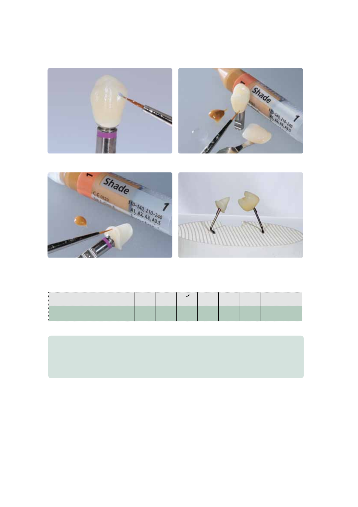
Apply IPS e.max Ceram Shade Incisal to imitate the incisal area.
Enhance the chroma of the buccal surface.
Individual characterization of the emergence profile with IPS e.max Ceram Essences.
Conduct the Stain and Characterization firing on a honey-comb firing tray.
Firing parameters for the Stain and Characterization firing
IPS e.max Ceram on IPS e.max Press
Abutment Solutions
B
°C
S
mint°C/min
T
°C
H
min
V
1
°C
Stain and Characterization firing 403 6:00 60 770 01:00 450 769 500
V
2
°C
Additional Stain and Characterization firing cycles can be conducted with the same firing parameters.
Note:
If the layer thickness is less than 2 mm on the entire pressed object, long-term cooling (L) is not required to
produce a tension-free condition.
L
°C
26
Page 27

Glaze firing
Glaze firing is conducted with powder or paste glaze. On abutments, only the emergence profile is glazed.
Glaze firing may also take place at a later stage, i.e. when the crown is glazed. On abutment crowns, glaze
is applied to the entire outer surface.
The following procedure is recommended:
– Mix the glazing material (IPS e.max Ceram Glaze Paste or Powder) with the IPS e.max Ceram Glaze and Stain Liquids
allround or longlife to the desired consistency.
– Apply an even layer of glazing material covering all areas that are to be glazed.
– If required, the fluorescence may be increased by applying a fluorescing glazing materal (paste or powder).
– Important: Make sure that absolutely no materials are applied to the screw channel and the interface to the Ti base in
order not to compromise the fit.
– Make sure that no glaze material is present on the interface of abutments and abutment crowns prior to the firing cycle.
If necessary, carefully remove the glaze material.
– Conduct the Glaze firing on a honey-comb firing tray using the stipulated firing parameters. Please observe the special
firing parameters.
– Remove restoration from the furnace after completion of the firing cycle (wait for the acoustic signal of the furnace).
– Allow the objects to cool to room temperature in a place protected from draft.
– Do not touch the hot objects with metal tongs.
– If adjustments are required after Glaze firing (e.g. contact points), they may be applied using IPS e.max Ceram Add-on
(see page 28).
Application procedure – Fabrication Hybrid Abutment and Hybrid Abutment Crown
Apply an even layer of glaze material to the emergence profile of the abutment. Make
sure that no glaze material enters the screw channel.
Make sure that no glaze material is present on the interface of abutments and
abutment crowns prior to the firing cycle. If necessary, carefully remove the glaze
material.
Apply the glazing material evenly on the outer surface of the abutment crown. Make
Conduct the Glaze firing on a honey-comb firing tray with the corresponding
27
sure that no glaze material enters the screw channel.
parameters.
Page 28

Firing parameters for the Glaze firing
IPS e.max Ceram on IPS e.max Press
Abutment Solutions
Glaze firing 403 6:00 60 770
B
°C
S
mint°C/min
°C
T
H
min
1:00–
2:00
V
1
°C
450 769 500
V
2
°C
If the gloss is unsatisfactory after the first Glaze firing, further Glaze firing procedures may be conducted
using the same firing parameters.
Note:
If the layer thickness is less than 2 mm on the entire pressed object, long-term cooling (L) is not required to
produce a tension-free condition.
L
°C
Completely glazed and characterized abutment and abutment crown
Adjustments with IPS e.max Ceram Add-On
Use IPS e.max Ceram Add-On Dentin and/or Incisal to make adjustments to the abutment or
abutment crown after Glaze firing. Please observe the following procedure for processing:
– Mix IPS e.max Ceram Add-On Dentin or Incisal with IPS e.max Ceram Build-Up Liquid soft or
allround and apply on the corresponding areas.
– Fire with the stipulated parameters for the "Add-On after Glaze firing". Observe long-term cooling!
If necessary, polish the adjusted areas to a high gloss after firing.
Firing parameters IPS e.max Ceram Add-On after Glaze firing.
IPS e.max Ceram on IPS e.max Press
Glaze firing 403 6:00 50 700 01:00 450 699 500
B
°C
S
min.t°C/min
28
T
°C
H
min
V
1
°C
V
2
°C
L
°C
Page 29

Optional: Polishing the emergence profile of the abutment
If no characterizations and no glaze firing of the abutment are required, the emergence profile may be
manually polished. Please remember that polishing results in a slight reduction of the emergence profile,
which might influence the fit to the gingiva in certain situations.
Please observe the following procedure for polishing:
– Clean the pressed object with a steam cleaner to remove any contaminations.
– Place the pressed object onto the Ti base for processing.
– Overheating of the glass-ceramic must be avoided. Observe the recommendations of the manufacturer of the grinding
tool.
– Pre-polish the emergence profile with a diamond-coated rubber polisher. Note: The Ti base should not be modified.
– Fine polishing of the emergence profile with a high-gloss rubber polisher.
– High-gloss polishing with brushes and polishing paste.
– Clean the abutment with an ultrasonic or steam cleaner.
Application procedure – Fabrication Hybrid Abutment and Hybrid Abutment Crown
Pre-polish the emergence profile with a diamond-coated rubber polisher.
Then clean the abutment with ultrasonic ...
High-gloss polishing with brushes and polishing paste.
... or with steam.
29
Page 30
Crown on hybrid abutment
IN STR UC TIO NS F OR U SE
Press
all ceramic
all you need
emax Press-VA 2009-d_emax Press-VA-d.qxd 22.09.11 14:13 Seite 1
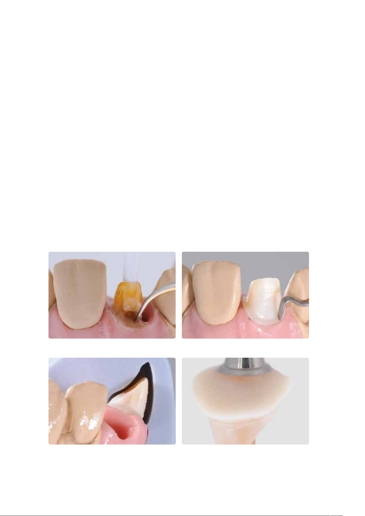
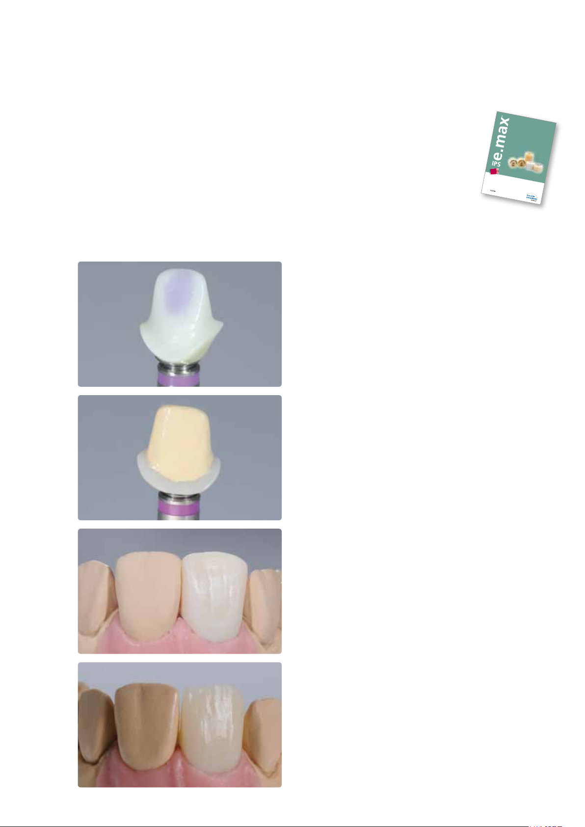
Preferably, a crown made of IPS e.max Press is seated on an IPS e.max Press hybrid abutment. Depending on your
preference, the staining, cut-back or layering technique may be applied for this. For a detailed description of the
fabrication, please refer to the IPS e.max Press Instructions for Use.
The following paragraphs describe the working steps which deviate from the procedure applied for the fabrication of
restorations on prepared teeth. In this example, an IPS e.max Press crown is fabricated in the cut-back technique.
Screw the Ti base onto the model analog with the
corresponding screw. If required, the abutment
can be secured on the Ti base by means of Virtual
Extra Light Body Fast Set.
Seal the screw channel (e.g. with silicone).
Before contouring the crown, apply a spacer up to
approx. 1 mm from the cervical crown margin.
Isolate the abutment and then contour the crown
with wax.
Finally, the restoration is pressed with IPS e.max
Press material.
Pressed IPS e.max Press crown with cut-back after
divesting and finishing.
30
Page 31

Complete the anatomical shape of the reduced
areas using IPS e.max Ceram layering materials,
such as Incisal and Opal.
Finish the restoration with diamonds and give it a
true-to-nature shape and surface structure.
Finally, conduct the Stain and Glaze firing with
IPS e.max Ceram Shades, Essences and Glaze.
Application procedure – Fabrication Hybrid Abutment and Hybrid Abutment Crown
Abutment and matching crown after Characterization and Glaze firing.
31
Page 32

®
e.max
IPS
Press Abutment Solutions
Optional: Clinical Try-in
Temporarily securing the pressed object on the Ti base
Before the abutment or abutment crown is permanently luted to the Ti base, a clinical try-in may be performed. To
facilitate the intraoral handling, the components are temporarily arttached to one another with silicone material,
e.g. Virtual® Extra Light Body Fast Set.
Please observe the following procedure to temporarily secure the components in place:
– Clean the non-pre-treated Ti base and the pressed object (abutment or abutment crown) with steam and blow dry.
– Place the pressed object on the Ti base (which is screwed to the model analog) and mark the relative position of the
components. This facilitates the achievement of the correct position when the parts are subsequently temporarily
assembled.
– Seal the screw channel with a foam pellet.
– Insert the Virtual cartridge into the dispenser and remove the protective cap.
– Screw on the mixing tip and attach the Oral Tip to the mixing tip.
– Apply Virtual Extra Light Body Fast Set both to the Ti base and directly into the pressed object.
– Insert the Ti base into the pressed object. Observe the relative position of the objects (rotation lock/marking).
– Hold the parts in the correct relative position for 2:30 minutes until the Virtual Extra Light Body Fast Set has set.
– Carefully remove protruding excess material with a suitable instrument, e.g. a scalpel.
Cleaned, non-pre-treated pressed objects (abutment or abutment crown)
Seal the screw channel with a foam pellet.
Place the abutment or abutment crown onto the Ti base and mark the relative position.
Insert the Virtual cartridge into the dispenser, screw on the mixing tip and attach the
32
Oral Tip.
Page 33

Application procedure – Optional: Clinical try-in
Apply Virtual Extra Light Body Fast Set both to the Ti base ...
Insert the Ti base into the pressed object. In doing so, observe the relative position of
the two components (rotation lock/marking). Hold the components in place for
approx. 2:30 minutes until the Virtual Extra Light Body Fast Set material has set.
... and directly into the pressed object (abutment/abutment crown).
Carefully remove protruding excess material with a suitable instrument, e.g. a scalpel.
Remove excess Virtual Extra Light Body Fast Set material from the screw channel with
an instrument.
33
Page 34

Clinical try-in
Hybrid abutment
Important note: Any intraoral checking of the occlusion/articulation and possible adjustments by grinding may only be
performed if the objects have been attached to one another by means of Virtual Extra Light Body Fast Set. During try-in,
the Virtual material acts as a buffer, particularly if grinding is necessary, and prevents chipping in the transition area
between the hybrid abutment and the crown.
Please observe the following procedure for the clinical try-in:
– Have the clean prepared hybrid abutment (temporarily secured) and the matching clean crown ready at hand.
– Remove the temporary restoration.
– Manually screw in the hybrid abutment with the matching screw.
– Check the geometry of the hybrid abutment (e.g. fit, gingival anaemia) with regard to the gingival margin.
– If required, seal the screw channel on the hybrid abutment with a foam pellet.
– Tip: Isolate the inner aspect of the crown with glycerin gel, e.g. Try-in paste, Liquid Strip
– Place the crown intraorally onto the hybrid abutment to check and adjust the proximal contacts, if necessary.
Note: No occlusal functional checks must be performed at this stage.
– For the functional check, the crown has to be secured on the hybrid abutment with Virtual Extra Light Body
Fast Set. Do not use Try-in paste for this purpose, as this material is not sufficiently resistant against the
compressive forces.
– Insert the Virtual cartridge into the dispenser and remove the protective cap.
– Screw on the mixing tip and attach the Oral Tip to the mixing tip.
– Apply Virtual Extra Light Body Fast Set to the inner aspect of the crown.
– Use your finger to press the crown to the hybrid abutment until the final position has been achieved. Hold the crown in
the final position until the Virtual material has set.
– Remove excess Virtual material.
– Check the occlusion/articulation and make required adjustments with suitable grinding instruments (see separate
IPS e.max Recommended grinding instruments for ceramics – use in the dental practice). If adjustments have been made
by grinding, conduct another polishing cycle or glaze firing.
– Carefully remove the crown from the hybrid abutment and the hybrid abutment (including Ti base).
– Insert the temporary restoration.
Manually screw in the hybrid abutment with the matching screw. Check the geometry
of the hybrid abutment (e.g. fit, gingival anaemia) with regard to the gingival margin.
If required, seal the screw channel of the hybrid abutment with a foam pellet.
34
Page 35

Application procedure – Optional: Clinical try-in
Tip: Isolate the inner aspect of the crown with glycerine gel.
Apply Virtual Extra Light Body Fast Set to the inner aspect of the crown.
Place the crown intraorally onto the hybrid abutment to check and adjust the proximal
contacts, if necessary. Note: No occlusal functional checks must be performed
Use your finger to press the crown to the hybrid abutment until the final position has
been achieved. Hold the crown in the final position until the Virtual material has set.
at this stage.
Remove excess Virtual material.
Carefully remove the crown from the hybrid abutment and remove the
Virtual Extra Light Body Fast Set material.
Check the occlusion/articulation and use suitable grinding instruments to make
possibly required adjustments.
Unscrew the hybrid abutment.
35
Page 36

Hybrid abutment crown
Please observe the following procedure for the clinical try-in:
– Have the cleaned hybrid abutment crown (temporarily secured with Virtual Extra Light Body Fast Set) at hand.
– Remove the temporary restoration.
– Place the hybrid abutment crown intraorally onto the implant to check and possibly adjust the proximal
contacts. Note: No occlusal functional checks must be performed at this stage.
– Manually screw in the hybrid abutment crown with the matching screw.
– Check the geometry of the hybrid abutment crown (e.g. fit, gingival anaemia) with regard to the gingiva.
– Check the occlusion/articulation and make possibly required adjustments with suitable grinding instruments (see separate
IPS e.max Recommended grinding instruments for ceramics – use in the dental practice). If adjustments have been made
by grinding, conduct another polishing cycle or glaze firing.
– Carefully remove the hybrid abutment crown (including Ti base).
– Rinse the implant site e.g. with Cervitec Liquid (antibacterial mouth wash with chlorhexidine) to clean and disinfect it.
– Insert the temporary restoration.
Place the hybrid abutment crown intraorally onto the implant to check and possibly
adjust the proximal contacts. Note: No occlusal functional checks must be
performed at this stage.
Manually screw in the hybrid abutment crown with the matching screw.
Check the geometry of the hybrid abutment crown (e.g. fit, gingival anaemia) with
regard to the gingiva.
Check the occlusion/articulation and use suitable grinding instruments to make
possibly required adjustments.
Carefully remove the hybrid abutment crown (including Ti base).
36
Page 37

®
e.max
IPS
Press Abutment Solutions
Permanent Cementation
Careful preparation of the bonding surface is a prerequisite for an optimum adhesive cementation of the
Ti base and the pressed object. The following paragraphs outline the required procedures. The procedure is
the same for hybrid abutments and hybrid abutment crowns.
IPS e.max Press Abutment Solutions
Abutment,
abutment crown
Blasting –
Etching
Conditioning/silanating
Adhesive cementation Multilink
Covering the cementation joint Glycerine gel, e.g. Liquid Strip
The bonding area with
®
Ceramic Etching Gel for 20 s
IPS
with Monobond
The bonding area
®
The bonding area with Al
®
Plus for 60 s
Implant MO 0
Ti base
at low pressure
–
2O3
Application procedure – Permanent Cementation
Curing
Polishing the cementation joint Customary polishers for ceramic/resin materials
All the materials that are required for permanent cementation
and for clinical try-in are contained both in the IPS e.max Press
Abutment Solutions Basic Kit A–D* and the IPS e.max
Abutment Solutions Cem Kit*.
* The range of available products may vary from country to country.
(optionally in a light-curing device)
7-minute curing
37
Page 38

Pre-treatment of the Ti base
To prepare the Ti base for cementation with the pressed object, please observe the following procedure:
– Observe processing instructions of the manufacturer of the Ti base.
– Clean the Ti base in an ultrasonic cleaner and blow dry or use a steam cleaner.
– Screw Ti base onto a model analog.
– Place the pressed object on the Ti base and mark the relative position of the components. This facilitates locating the
correct position when the parts are assembled at a later stage.
– The emergence profile of the Ti base must not be blasted or modified in any way. To protect the emergence profile,
hard modelling wax is applied, as this material can be easily removed later on.
– Seal the screw channel with wax.
– Carefully blast the bonding area with Al2O3 (50–100 µm) at low pressure until an even mat surface has been achieved.
– Clean with an instrument and steam cleaner. Make sure that any wax residue is carefully removed.
– After cleaning, any contamination of the bonding surface must be prevented, since contaminations negatively influence
the bond.
– Apply Monobond Plus on the cleaned bonding surface and allow to react for 60 seconds. After the reaction time, dry
the remaining residue with water- and oil-free air.
– Seal the screw channel with a foam pellet or wax. Make sure that the bonding surface is not contaminated.
Screw Ti base onto a model analog. Mark the relative position to the
pressed object.
Carefully blast the bonding area with Al
mat surface has been achieved.
(50–100 µm) at low pressure until an even
2O3
Apply wax to protect the emergence profile. In addition, seal also the screw channel
Clean with an instrument and steam cleaner. Make sure that any
38
wax residue is carefully removed.
with wax.
Page 39

Application procedure – Permanent Cementation
Apply Monobond Plus on the cleaned bonding surface and allow to react for
60 seconds. After the reaction time, dry the remaining residue with water-
and oil-free air.
Seal the screw channel with a foam pellet or wax.
Make sure that the bonding surface is not contaminated.
Preparing the pressed object
To prepare the pressed object for cementation onto the Ti base, please observe the following procedure:
– Do not blast the IPS e.max Press object to prepare it for cementation.
– Clean the pressed object in an ultrasonic cleaner and blow dry or use a steam cleaner.
– After cleaning, any contamination of the bonding surface must be prevented, since contaminations negatively influence
the bond.
– To protect the outer surfaces or the glazed areas, wax may be applied.
– Etch the bonding surface with 5% hydrofluoric acid gel (IPS Ceramic Etching Gel) for 20 seconds.
– Subsequently, thoroughly rinse the bonding surface under running water and dry with oil-free air.
– Apply Monobond Plus on the cleaned bonding surface and allow to react for 60 seconds. After the reaction time, dry
the remaining residue with water and oil-free air.
Do not blast IPS e.max Press object Etch with IPS Ceramic Etching Gel for 20 seconds. Allow Monobond Plus to react for 60 seconds
39
and dry with air.
Page 40
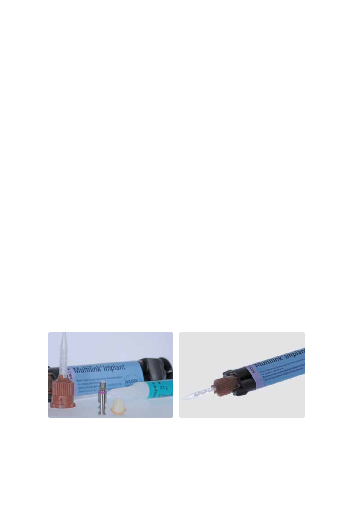
Cementation with Multilink® Implant
For an optimum bond between the IPS e.max Press object and the Ti base, use the self-curing luting composite Multilink®
Implant with light-curing option. Read the respective Instructions for Use for more detailed information.
Please observe the following procedure for cementation:
– Keep the cleaned and conditioned components that are to be luted (pressed objects, Ti base) at hand.
– The subsequent cementation procedure must be carried out quickly and without interruption. The working
time of Multilink Implant is 90 (± 15) seconds at 23 °C (± 1 °C) or 73 °F (± 1.8 °F).
– As a general rule, attach a new mixing tip to the Multilink Implant syringe prior to each use.
– Apply Multilink Implant directly from the mixing tip in a thin layer on the bonding surface of the Ti base and the
bonding surface of the pressed object.
– Leave the mixing tip attached to the Multilink Implant syringe until the next application. As the material will cure in the
mixing tip, it will serve as a seal.
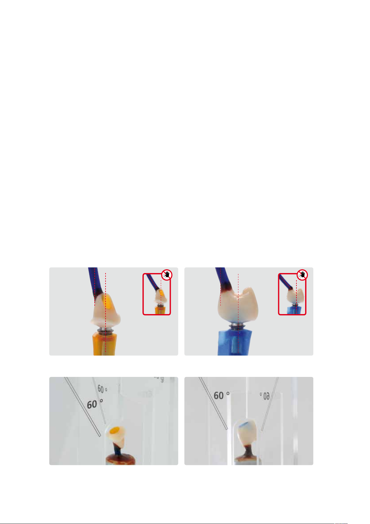
– Position the pressed object above the Ti base in such a way that the position markings are aligned.
– Use even and low pressure to join the parts and check the correct relative position of the components when they are in
their final position (transition Ti base/pressed object).
– Subsequently, tightly press the components together for 5 seconds.
– Carefully remove excess in the screw cavity, e.g. with Microbrush or brush, using a rotary movement.
– Remove excess at the transition to the Ti base carefully in its ductile state, e.g. with a foam pellet, while applying slight
pressure to hold the components in place.
– Apply a glycerine gel (e.g. Liquid Strip) to the cementation joint to prevent the formation of a inhibition layer.
– After that, completely polymerize the luting composite for 7 minutes in a light-polymerization device.
– Important: Do not move the objects until the Multilink Implant material has completely cured and hold them
in place without allowing for any motion, e.g. with diamond-coated tweezers.
– After completion of the polymerization, rinse off the glycerine gel with water.
– Smooth out and polish the cementation joint with rubber polishers.
– If there are any cement residues in the screw channel, remove them using suitable rotary instruments.
– Clean with a steam cleaner.
Keep the cleaned and conditioned components that are to be luted at hand. Attach a new mixing tip to the Multilink Implant syringe prior to each use.
40
Page 41

Application procedure – Permanent Cementation
Apply Multilink Implant directly from the mixing tip in a thin layer on the bonding
surface of the Ti base.
Position the pressed object above the Ti base in such a way that the position markings
are aligned.
Apply Multilink Implant directly from the mixing tip in a thin layer on the bonding
Join the components using even and light pressure. Subsequently, tightly press the
surface of the pressed object.
components together for 5 seconds.
Carefully remove excess in the screw cavity, e.g. with a Microbrush or a brush, using a
rotary movement.
Apply a glycerine gel (e.g. Liquid Strip) to the cementation joint to prevent the
formation of a inhibition layer.
Remove excess carefully in its ductile state, e.g. with a foam pellet, while applying
Polymerize the luting composite for 7 minutes (optionally in a light-curing unit).
Important: Do not move the objects until the material has completely
cured and hold them in place without allowing for any motion.
slight pressure to hold the components in place.
41
Page 42

After completion of the polymerization, rinse off the glycerine gel with water.
Smooth out and polish the cementation joint with rubber polishers.
If there is any cement residue in the screw channel, remove using suitable rotary
instruments. Do not damage the Ti base.
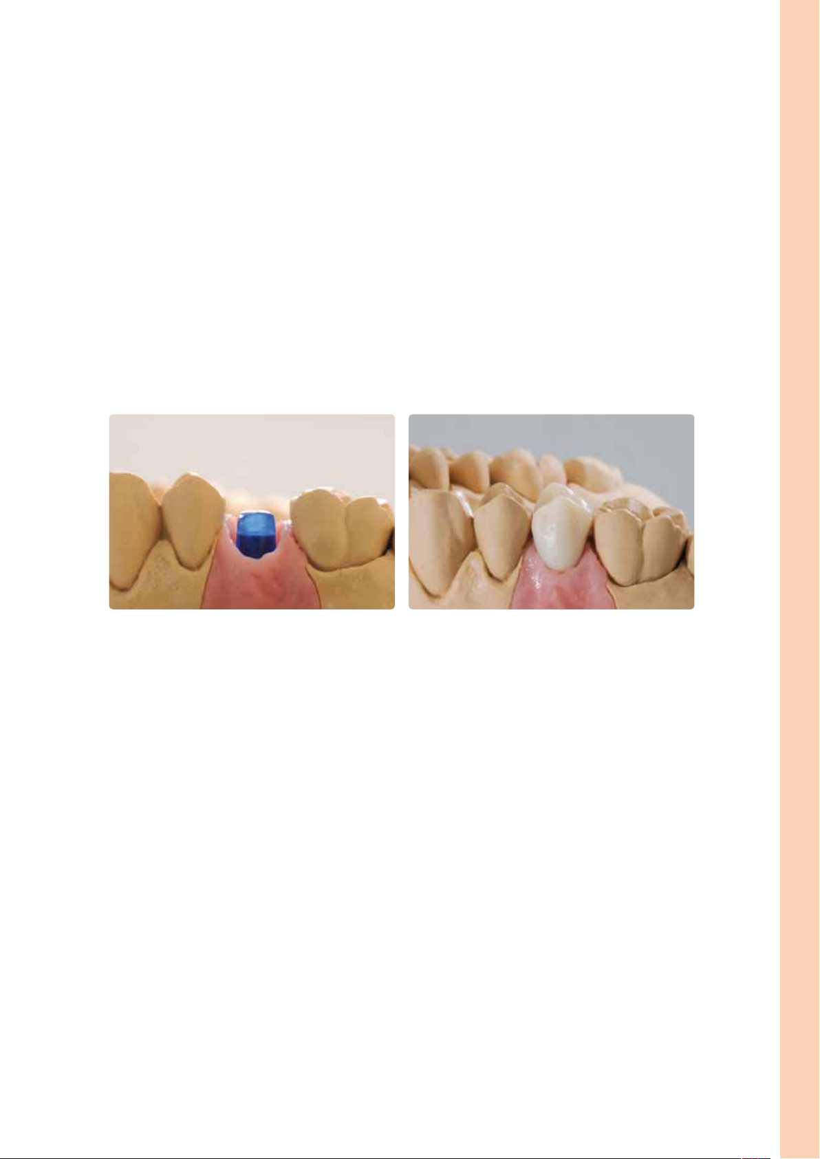
Completed hybrid abutment and hybrid abutment crown after cementation.
42
Page 43

®
e.max
IPS
Press Abutment Solutions
Seating and Aftercare
Sterilization
We recommend sterilizing hybrid abutments or hybrid abutment crowns before seating
them in the patient's mouth.
– The sterilization time is 15 minutes at 121 °C / 250 °F.
– Only devices which comply with the standards EN 13060 and EN 285 should be
used for sterilization. The sterilization processes are validated according to
EN ISO-17664:2004.
Intraoral preparation
Please observe the following procedure to prepare for the permanent cementation of the implant-supported restoration:
– Remove the temporary restoration.
– Clean the implant site.
– Check the periimplant tissue (emergence profile).
Application procedure – Seating and Aftercare
Seating the hybrid abutment and crown
Preparing/conditioning the hybrid abutment and crown
Conditioning of the ceramic surface, i.e. the bonding surface, in preparation for cementation is critical for generating a
sound bond between the cementation material and the all-ceramic material.
The following steps must be observed:
– Do not blast the IPS e.max Press hybrid abutment or the IPS e.max Press crown with Al2O3 or glass polishing beads prior
to seating.
– Ideally, conduct the clinical try-in before etching in order not to contaminate the bonding surface.
– Thoroughly clean the hybrid abutment and the crown with water and blow dry.
– Etch the bonding surfaces with 5% hydrofluoric acid gel (IPS Ceramic Etching Gel) for 20 seconds. Make sure that no
etching gel comes into contact with the emergence profile or the outer side of the crown. Important: Do not use the
IPS Ceramic Etching Gel intraorally.
– Thoroughly rinse off the etching gel with water and dry with oil- and water-free air.
– If an adhesive or self-adhesive cementation protocol is used, apply Monobond Plus to the bonding surfaces,
allow to react for 60 seconds and then dry with oil- and water-free air.
Do not blast IPS e.max Press objects. Etch the bonding surfaces with IPS Ceramic Etching Gel
for 20 seconds.
43
Apply Monobond Plus to the bonding areas,
allow to react for 60 s and blow dry.
Page 44

Seating the hybrid abutment and crown
For the permanent seating of the hybrid abutment and the crown, please observe the following working steps. Please also
observe the Instructions for Use of the selected luting material.
– Do not use phenolic mouth washes, as such products negatively influence the bond between the ceramic and the
composite.
– Insert the hybrid abutment intraorally into the implant.
– Manually screw in the matching implant screw.
– Tighten the implant screw with a torque wrench (observe the instructions of the manufacturer).
– Insert a cotton or foam pellet into the screw channel.
– Seal the screw channel with a temporary composite (e.g. Telio® CS Inlay). This serves to ensure access to the screw at a
later stage.
– Check the bonding area for contamination/moisture and clean or dry with an air syringe, if necessary.
– Apply the luting material, e.g. SpeedCEM®, into the conditioned crown.
– Place the crown onto the hybrid abutment and secure in place in the final position.
– Conduct the pre-polymerization using the four-quarter technique.
– Remove excess luting material.
– Cover the cementation joint with glycerine gel (e.g. Liquid Strip).
– Polymerize with an LED curing light (e.g. bluephase®).
– Rinse off the glycerine gel with water.
– Check the occlusion and articulation and make adjustments, if necessary. If adjustments are made to the restoration by
grinding, these areas must subsequently be polished to a high gloss, e.g. using OptraFine.
– Polish restoration margins and the cementation joint with silicone polishers (e.g. Astropol®, OptraFine).
– Apply Cervitec Plus in the area of the gingival margin.
Insert the hybrid abutment intraorally into the implant.
Tighten the implant screw with a torque wrench (observe the instructions of the
manufacturer).
Manually screw in the matching implant screw.
Seal the screw channel, for instance with a cotton or foam pellet
44
and a temporary composite material.
Page 45

Application procedure – Seating and Aftercare
Apply the luting material, e.g. SpeedCEM, into the conditioned crown.
Conduct the pre-polymerization using the four-quarter technique.
Place the crown onto the hybrid abutment and secure in place.
Remove excess luting material.
Cover the restoration margin with glycerine gel (e.g. Liquid Strip).
Rinse off the glycerine gel with water. Check the occlusion and articulation and make adjustments, if necessary.
Polymerize with an LED curing light (e.g. bluephase).
45
Page 46

Polish restoration margins and the cementation joint with polishers (e.g. Astropol,
OptraFine).
Completed IPS e.max Press hybrid abutment and crown.
46
Page 47

Seating the hybrid abutment crown.
Preparing/conditioning the hybrid abutment crown
Please observe the following notes to prepare for the intraoral sealing of the screw channel:
– As a general rule, do not blast IPS e.max Press hybrid abutment crowns with Al2O3 or glass polishing beads.
– Thoroughly clean the the hybrid abutment crown with water and blow dry.
– Etch the screw channel from the occlusal side with 5% hydrofluoric acid gel (IPS Ceramic Etching Gel) for 20 seconds.
Make sure that no etching gel comes into contact with the occlusal surface. Important: Do not use the IPS Ceramic
Etching Gel intraorally.
– Thoroughly rinse off the etching gel with water and dry with oil- and water-free air.
– Apply Monobond Plus to the etched and cleaned surface in the screw channel, allow to react for 60 seconds and then
blow dry with oil- and water-free air.
Application procedure – Seating and Aftercare
Do not blast IPS e.max Press object Etch with IPS Ceramic Etching Gel for 20 seconds. Apply Monobond Plus and allow to react for 60 seconds
Seating the hybrid abutment crown.
For the permanent seating of the hybrid abutment crown, please observe the following working steps.
– Do not use phenolic mouth washes, as such products negatively influence the bond between the ceramic and the
composite.
– Insert the hybrid abutment crown intraorally into the implant.
– Manually screw in the matching implant screw.
– Tighten the implant screw with a torque wrench (observe the instructions of the manufacturer).
– Check the screw channel for contamination/moisture and clean with Total Etch (phosporic acid gel), if necessary.
– Insert a cotton or foam pellet into the screw channel.
– Apply the bonding agent.
– Seal the screw channel with a composite material (e.g. Tetric EvoCeram) in the appropriate shade.
– Polymerize with an LED curing light (e.g. bluephase).
– Check the occlusion/articulation after polymerization and correct possible rough spots with suitable fine-grain diamonds.
– Polish to a high gloss with silicone polishers (e.g. OptraFine).
and blow dry with air.
47
Page 48

Insert the hybrid abutment crown intraorally into the implant.
Manually screw in the matching implant screw.
Tighten the implant screw with a torque wrench (observe the instructions of the
manufacturer).
Polymerize with an LED curing light (e.g. bluephase).
Seal the screw channel with a composite material (e.g. Tetric EvoCeram) in
After polymerization, check the occlusion/articulation and correct possible rough spots
with suitable finishers (e.g. Astropol F) or fine diamonds.
the appropriate shade.
Polish to a high gloss using silicone polishers (e.g. Astropol P, Astropol HP or
Astrobrush).
Completed IPS e.max Press hybrid abutment crown
48
Page 49

Care Notes – Implant Care
Implant Care
Implant restorations protected
all around
Cervitec Gel
the oral health care
gel with chlor -
hexidine and fluoride
Cervitec
Liquid
the antibacterial
mouth rinse
Cervitec Plus
the protective varnish with
chlorhexidine
Proxyt
the fine prophy paste
Optra Gate
the flexible lip and
cheek retractor
Plaque Test
the fluorescent
disclosing li quid
Implant Care_SalesChart_170x120_E_627940_Layout 1 27.09.11 16:23 Seite 1
Implant Care comprises a range of coordinated products for the professional care of patients during the various phases of
implant treatment and lifelong aftercare. Products for professional tooth cleaning and bacterial control contribute to the
long-term quality assurance of implant-supported restorations. Structural elements, peri-implant tissue, natural teeth, dental
restorations, gingiva and the mucosa are treated in an optimum way with regard to function and esthetics.
Application procedure – Seating and Aftercare
49
Page 50

®
e.max
IPS
Press Abutment Solutions
General Information
Frequently Asked Questions
In addition to the desired tooth shade, why
should the root shade also be defined/
determined upon shade determination?
IPS e.max Press Abutment Solutions allow you to
fabricate restorations with a lifelike appearance
both in the visible area and the area below the
gingiva (root). By defining the root shade, a highly
esthetic outcome can be achieved especially
receding gingiva.
Is it possible to fabricate an abutment or an
abutment crown with IPS e.max Press (LS2)
without using a Ti base?
No! For this indication, IPS e.max Press needs the
support provided by the Ti base. In addition, the Ti
base allows an optimum (industrially fabricated) fit
to the implant to be achieved.
Is it possible to use any commercially
available Ti base in conjunction with
IPS e.max Press Abutment Solutions?
When selecting a suitable Ti base, the requirements
in terms of minimum dimensions (height, shoulder
width, no undercuts) must be taken into account.
In addition, the Ti base must be equipped with a
rotation lock which does not entail a reduction of
the ceramic layer thickness.
Is it permissible to modify the selected
Ti base?
The instructions of the manufacturer with regard
to modifying the Ti base must be observed. Prior
to permanent cementation, the bonding surface of
the Ti base must be blasted with Al2O3.
Is a hybrid abutment crown indicated in the
anterior region?
This indication depends on the position and inclination of the implant. If the opening of the screw
channel is located on the lingual/palatinal surface,
a hybrid abutment crown may be fabricated in the
anterior region.
Is it possible to use an IPS e.max Press hybrid
abutment as an abutment for a bridge
restoration?
No. Only single-tooth restorations may be
fabricated.
What do I need to take into consideration
when designing a hybrid abutment or hybrid
abutment crown in order to fabricate a
durable restoration?
The stipulated minimum and maximum layer thicknesses for IPS e.max Press need to be observed. In
addition, the ratio between the height of the Ti
base and the height of the entire restoration must
be observed.
What do I need to take into consideration
when attaching sprues and investing the
wax-up?
The screw channel of the sprued wax-up must be
parallel to the outer wall of the investment ring.
As a result, the investment material can be filled
evenly and in a controlled manner. In addition, the
risk that the flowing ceramic material could break
off the investment material in the screw channel is
reduced. The objects could be placed in a tilted
position on the investment ring base, but this may
lead to difficulties during investing (e.g. bubbles in
the screw channel).
If the screw channel is very long, the investment
material in the screw channel can be stabilized
with a pin (e.g. high-grade steel, ZrO
investing. For this purpose, pour investment
material into the investment ring up to the
restoration margin, insert the pin into the screw
channel and fill up the investment ring up to the
marking without vibrating it.
When is the sprue of the pressed object
separated?
We recommend that the pressed objects should
be fitted to the Ti base first, as this facilitates the
handling. Subsequently, the pressed objects are
separated from the sprue.
) during
2
50
Page 51

How should the emergence profile of the
hybrid abutment be finished?
Preferably, a Characterization and Glaze firing is
conducted on the emergence profile prior to the
cementation procedure. In this way, you may
adjust the esthetic appearance of the abutment to
the clinical situation ("root shade"). If no characterization is required, the emergence profile may
be polished to a high gloss with polishers as well
as brushes and paste.
Is it possible to use IPS e.max Ceram Glaze
Spray to glaze the abutment or the abutment
crown?
We do not recommend using the Glaze Spray in
this indication, as the bonding surface and the
screw channel may be contaminated with glaze
material.
An optional clinical try-in may be performed.
How are the objects prepared for this?
The Ti base and the pressed abutment or abutment
crown are temporarily joined in the laboratory by
means of a silicone material, e.g. Virtual Extra
Light Body Fast Set. This facilitates the intraoral
handling.
What material is used to permanently cement
the abutment or the abutment crown made
of IPS e.max Press with the Ti base?
Only Multilink Implant is to be used for the permanent cementation. Other luting materials have
not been tested for this purpose.
How is the Ti base prepared for the permanent cementation with Multilink Implant?
Carefully blast the bonding area with Al
2O3
at low
pressure until an even mat surface has been
achieved. After cleaning, the area is conditioned
with Monobond Plus.
How is the screw channel of a hybrid
abutment crown sealed intraorally?
After the hybrid abutment crown has been
screwed into place and the screw has been
tightened with a torque wrench, the screw
channel is sealed with a composite restorative
material.
General Information – Frequently Asked Questions
What must be observed for the clinical try-in
of a crown on a hybrid abutment?
To check the occlusion/articulation and to make
possible adjustments, the crown must be temporarily secured on the hybrid abutment with a silicone material, e.g. Virtual Extra Light Body Fast
Set. The silicone material acts as a buffer and prevents chipping in the marginal area of the crown.
Try-in pastes or Vaseline must not be used for
functional checks.
51
Page 52

Material Selection Table
Ti base
LT
D4
LT
D3
LT
D2
LT
C4
LT
C3
LT
C2
LT
C1
LT
B4
LT
B3
LT
B2
LT
B1
Ti base
LT
D4
LT
D3
LT
D2
LT
C4
LT
C3
LT
C2
LT
C1
LT
B4
LT
B3
LT
B2
LT
B1
Multilink Implant MO 0
Desired tooth shade: Bleach BL and A-D Shade Guide
BL1 BL2 BL3 BL4 A1 A2 A3 A3,5 A4 B1 B2 B3 B4 C1 C2 C3 C4 D2 D3 D4
HO HO 0 HO 1 HO 2 HO 1 HO 2 HO 1 HO 2
MO – MO 0 MO 1 MO 2 MO 0 MO 2 MO 0 MO 2 MO 0 MO 1
LT
A4
e.g. Multilink Implant, SpeedCEM, etc.
LT
A3.5
adhesive, self-adhesive or conventional cementation
LT
A3
LT
A2
LT
A1
LT
BL4
LT
BL3
LT
BL2
LT
BL1
Multilink Implant MO 0
LT
A4
LT
A3.5
Desired tooth shade: Bleach BL and A-D Shade Guide
BL1 BL2 BL3 BL4 A1 A2 A3 A3,5 A4 B1 B2 B3 B4 C1 C2 C3 C4 D2 D3 D4
LT
A3
LT
A2
LT
A1
LT BL1 LT BL2 LT BL3 LT BL4
Hybrid abutment and separate crown
The material is selected on the basis of the desired tooth shade (Bleach BL or A–D). Depending on the Ti base selected and the design of the hybrid abutment or crown, characterizations with
IPS e.max Ceram Shades and Essences may be necessary to achieve the desired shade.
The desired tooth shade is achieved after the restoration has been seated and is made up of the shade of the hybrid abutment and the shade of the crown that is cemented onto it. The ingot
recommendations for the hybrid abutment have been selected in such a way that the desired tooth shade is achieved in combination with the crown. In the "cervical area", it may be necessary
to characterize the hybrid abutment according to the clinical situation.
Cementation in the labora-
tory
Ingot* for the
hybrid abutment
Cementation (intraoral)
IPS e.max Press crown
52
* Given the high opacity, HO ingots are better suited to cover the (grey) titanium bases. These ingots may also be used for thinner hybrid abutment designs.
Hybrid abutment crown
The material is selected on the basis of the desired tooth shade (Bleach BL or A–D). Depending on the Ti base selected and the design of the hybrid abutment crown, characterization with
IPS e.max Ceram Shades and Essences may be necessary to achieve the desired shade.
Cementation in the labora-
tory
Abutment crown
IPS e.max Press
Page 53

Press and Firing Parameters
Press parameters for IPS e.max Press
The press furnace, investment ring size and the selected IPS e.max Press ingot must be considered:
Press furnace IPS e.max Press
EP 500
Press furnace IPS e.max Press
EP 600
ingots
HO, MO, LT
HT
ingots
HO, MO, LT
Combi
HT
Programat EP 3000
IPS Investment
Ring System
100 g
200 g
100 g
200 g
IPS Investment
Ring System
100 g
200 g
100 g
200 g
B t➚ T H V1 V2
°C °C/min °C min °C °C
700 60 925 15 500 925
Software 2.9
700 60 930 25 500 930
Software 2.9
700 60 920 15 500 920
Software 2.9
700 60 925 25 500 925
Software 2.9
B t➚ T H A
°C °C/min °C min
700 60 915 15 300 µm/min
700 60 920 25 300 µm/min
700 60 910 15 300 µm/min
700 60 915 25 300 µm/min
Program 11-20
Program 11-20
Program 11-20
Program 11-20
Select the press program in accordance with the selected ingot to be pressed
and the investment ring size used.
General Information – Material Selection Table | Press and Firing Parameters
The press parameters for HO, MO, LT and HT are integrated starting
with software V 6.1.
Programat EP 5000
Select the press program in accordance with the selected ingot to be pressed
and the investment ring size used.
The press parameters for HO, MO, LT and HT are integrated starting
with software V 6.1.
– The firing parameters listed represent standard values and apply to the Ivoclar Vivadent furnaces P300, P500, P700,
EP 3000 and EP 5000. The temperatures indicated also apply to furnaces of older generations. However, the temperature
in the firing chamber may deviate by approx. ± 10 °C/18 °F, depending on the age of the heating muffle.
– If a non-Ivoclar Vivadent furnace is used, temperature corrections may be necessary.
– Regional differences in the power supply or the operation of several electronic devices by means of the same circuit
may also render adjustments of the temperatures necessary.
53
Page 54

Firing parameters for IPS e.max Press Abutment Solutions
– Use a honey-comb tray and the corresponding pins for firing.
– Do not use ceramic pins.
– The stipulated parameters are coordinated with Ivoclar Vivadent furnaces (tolerance range +/- 10 °C/18 °F).
– If furnaces other than those from Ivoclar Vivadent are used, temperature adjustments may be necessary.
– Remove IPS e.max Press objects from the furnace after completion of the firing cycle (wait for the acoustic signal of the
furnace).
– Allow the objects to cool to room temperature in a place protected from draft.
– Do not touch the hot objects with metal tongs.
– Do not blast or quench the objects.
Note regarding the firing parameters for IPS e.max Press Abutment Solutions:
Given the geometry of hybrid abutments and hybrid abutment crowns, the layer thicknesses of the pressed object may vary
considerably. When the objects cool after the firing cycle, the different cooling speeds in the areas with different thicknesses
may result in internal tensions. In the worst case, these tensions may result in fractures in the pressed ceramic objects. By
using slow cooling (long-term cooling (L)), these tensile stresses can be minimized.
Note:
Please read the notes of the manufacturer of the ceramic furnace for more details on the programming of the long-term
cooling (L). If the layer thickness is less than 2 mm on the entire pressed object, long-term cooling (L) is not required.
IPS e.max Ceram on IPS e.max Press
Abutment Solutions
Stain and Characterization firing 403 6:00 60 770 01:00 450 769 500
Glaze firing 403 6:00 60 770
Add-On after Glaze firing 403 6:00 50 700 01:00 450 699 500
B
°C
S
mint°C/min
T
°C
H
min
1:00 –
2:00
V
1
°C
450 769 500
V
2
°C
L
°C
54
Page 55

Clinical cases (R. Watzke, Liechtenstein)
IPS e.max Press hybrid abutment / IPS e.max Press crown (area 36), IPS e.max Press crown (area 37).
General Information – Press and Firing Parameters
Clinical situation after implantation and gingiva shaping
Final image, buccal view: IPS e.max Press crown cemented onto an
IPS e.max Press hybrid abutment
IPS e.max Press hybrid abutment (36) and IPS e.max Press crown,
IPS e.max Press single crown
Final image, occlusal view: IPS e.max Press crown cemented onto an
IPS e.max Press hybrid abutment
IPS e.max Press hybrid abutment crown (area 35)
IPS e.max Press hybrid abutment, screwed in,
cemented IPS e.max Press crown
Clinical situation after implantation and gingiva shaping
Sealing the screw channel with composite material (e.g. Tetric
EvoCeram)
IPS e.max Press hybrid abutment crown
Final image of an IPS e.max Press hybrid abutment crown
55
Screwing in the hybrid abutment crown
Page 56

Ivoclar Vivadent – worldwide
Ivoclar Vivadent AG
Bendererstrasse 2
FL-9494 Schaan
Liechtenstein
Tel. +423 235 35 35
Fax +423 235 33 60
www.ivoclarvivadent.com
Ivoclar Vivadent Pty. Ltd.
1 – 5 Overseas Drive
P.O. Box 367
Noble Park, Vic. 3174
Australia
Tel. +61 3 979 595 99
Fax +61 3 979 596 45
www.ivoclarvivadent.com.au
Ivoclar Vivadent Ltda.
Alameda Caiapós, 723
Centro Empresarial Tamboré
CEP 06460-110 Barueri – SP
Brazil
Tel. +55 11 2424 7400
Fax +55 11 3466 0840
www.ivoclarvivadent.com.br
Ivoclar Vivadent Inc.
2785 Skymark Avenue, Unit 1
Mississauga
Ontario L4W 4Y3
Canada
Tel. +1 905 238 5700
Fax +1 905 238 5711
www.ivoclarvivadent.com
Ivoclar Vivadent Marketing Ltd.
Rm 603 Kuen Yang
International Business Plaza
No. 798 Zhao Jia Bang Road
Shanghai 200030
China
Tel. +86 21 5456 0776
Fax +86 21 6445 1561
www.ivoclarvivadent.com
Ivoclar Vivadent Marketing Ltd.
Calle 134 No. 7-B-83, Of. 520
Bogotá
Colombia
Tel. +57 1 627 33 99
Fax +57 1 633 16 63
www.ivoclarvivadent.co
Ivoclar Vivadent SAS
B.P. 118
F-74410 Saint-Jorioz
France
Tel. +33 450 88 64 00
Fax +33 450 68 91 52
www.ivoclarvivadent.fr
Ivoclar Vivadent GmbH
Dr. Adolf-Schneider-Str. 2
D-73479 Ellwangen, Jagst
Germany
Tel. +49 (0) 79 61 / 8 89-0
Fax +49 (0) 79 61 / 63 26
www.ivoclarvivadent.de
Ivoclar Vivadent Marketing (India)
Pvt. Ltd.
503/504 Raheja Plaza
15 B Shah Industrial Estate
Veera Desai Road, Andheri (West)
Mumbai, 400 053
India
Tel. +91 (22) 2673 0302
Fax +91 (22) 2673 0301
www.ivoclar-vivadent.in
Ivoclar Vivadent s.r.l.
Via Isonzo 67/69
40033 Casalecchio di Reno (BO)
Italy
Tel. +39 051 611 35 55
Fax +39 051 611 35 65
www.ivoclarvivadent.it
Ivoclar Vivadent K.K.
1-28-24-4F Hongo
Bunkyo-ku
Tokyo 113-0033
Japan
Tel. +81 3 6903 3535
Fax +81 3 5844 3657
www.ivoclarvivadent.jp
Ivoclar Vivadent Ltd.
12F W-Tower, 1303-37
Seocho-dong, Seocho-gu,
Seoul 137-855
Republic of Korea
Tel. +82 (2) 536 0714
Fax +82 (2) 596 0155
www.ivoclarvivadent.co.kr
Ivoclar Vivadent S.A. de C.V.
Av. Insurgentes Sur No. 863.
Piso 14, Col. Napoles
03810 México, D.F.
México
Tel. +52 (55) 50 62 10 00
Fax +52 (55) 50 62 10 29
www.ivoclarvivadent.com.mx
Ivoclar Vivadent Ltd.
12 Omega St, Albany
PO Box 5243 Wellesley St
Auckland, New Zealand
Tel. +64 9 914 9999
Fax +64 9 814 9990
www.ivoclarvivadent.co.nz
Ivoclar Vivadent Polska Sp. z o.o.
Al. Jana Pawla II 78
00-175 Warszawa
Poland
Tel. +48 22 635 54 96
Fax +48 22 635 54 69
www.ivoclarvivadent.pl
Ivoclar Vivadent Marketing Ltd.
Derbenevskaja Nabereshnaya 11, Geb. W
115114 Moscow
Russia
Tel. +7 495 913 66 19
Fax +7 495 913 66 15
www.ivoclarvivadent.ru
Ivoclar Vivadent Marketing Ltd.
Qlaya Main St.
Siricon Building No.14, 2
nd
Floor
Office No. 204
P.O. Box 300146
Riyadh 11372
Saudi Arabia
Tel. +966 1 293 83 45
Fax +966 1 293 83 44
www.ivoclarvivadent.com
Ivoclar Vivadent Pte. Ltd.
171 Chin Swee Road
#02-01 San Centre
Singapore 169877
Tel. +65 6535 6775
Fax +65 6535 4991
www.ivoclarvivadent.com
Ivoclar Vivadent S.L.U.
c/ Emilio Muñoz Nº 15
Entrada c/ Albarracin
E-28037 Madrid
Spain
Tel. + 34 91 375 78 20
Fax + 34 91 375 78 38
www.ivoclarvivadent.es
Ivoclar Vivadent AB
Dalvägen 14
S-169 56 Solna
Sweden
Tel. +46 (0) 8 514 93 930
Fax +46 (0) 8 514 93 940
www.ivoclarvivadent.se
Ivoclar Vivadent Liaison Office
: Tesvikiye Mahallesi
Sakayik Sokak
Nisantas’ Plaza No:38/2
Kat:5 Daire:24
34021 Sisli – Istanbul
Turkey
Tel. +90 212 343 08 02
Fax +90 212 343 08 42
www.ivoclarvivadent.com
Ivoclar Vivadent Limited
Ground Floor Compass Building
Feldspar Close
Warrens Business Park
Enderby
Leicester LE19 4SE
United Kingdom
Tel. +44 116 284 78 80
Fax +44 116 284 78 81
www.ivoclarvivadent.co.uk
Ivoclar Vivadent, Inc.
175 Pineview Drive
Amherst, N.Y. 14228
USA
Tel. +1 800 533 6825
Fax +1 716 691 2285
www.ivoclarvivadent.us
Date information prepared: 11/2011
Some products and/or indications may not be regulatory cleared/released in all markets. Please contact the local
Ivoclar Vivadent sales office for the current national status.
These materials have been developed solely for use in dentistry. Processing should be carried out strictly
according to the Instructions for Use. Liability cannot be accepted for damages resulting from failure to
observe the Instructions or the stipulated area of application. The user is responsible for testing the products
for their suitability and use for any purpose not explicitly stated in the Instructions. Descriptions and data constitute no warranty of attributes and are not binding. These regulations also apply if the materials are used in
conjunction with products of other manufacturers.
Printed in Liechtenstein
© Ivoclar Vivadent AG, Schaan / Liechtenstein
641315/1111/e/BVD
 Loading...