

Page 1
Page 2

NEF SERIES
MECHANICAL INJECTION
SYSTEM
INTRODUCTION
We would like to thank you for buying an IVECO MOTORS
product, and compliment you on your choice of engine.
Before you carry out any operation involving the engine or its
fittings, please read the contents of this manual carefully; compliance
with the instructions provided in the manual is the best way to
guarantee trouble-free, long term operation of the engine.
N45 MNA - N45 MSA (TIER 2)
N45 MNS - N45 MSS (TIER 2/3)
N45 MNT - N45 MST (TIER 2/3)
N67 MNA - N67 MSA (TIER 2)
N67 MNT (TIER 2/3)
N67 MST (TIER 2)
NEF 45 SM1/SM2
NEF 45 TM1/TM2
NEF 67 SM1
NEF 67 TM2/TM3
SE AND MAINTENANCE
U
The contents of this manual refer to the standard configuration of
the engine, and the illustrations are purely indicative. Some
instructions are provided by giving the sequence of operations to be
carried out in order to allow the engine and/or its fittings to
perform in a certain way. In some cases they will be dependent on
the configuration of the commands and the set-up of the machine
on which the engine is installed; for any points that differ from the
contents of this manual, please consult the instructions provided by
the machine Manufacturer or a specific manual.
The information provided below was current at the date of
publication.
The Manufacturer reserves the right to make modifications at any
time without prior notice, for technical or commercial reasons or
to update the engines to comply with legal requirements in the
various Countries.
The Manufacturer declines all liability for any errors or omissions.
Please remember that the IVECO MOTORS Technical Service
Network is available to offer you its experience and professional
skills, wherever you may be.
1
ENGLISH
Page 3

TABLE OF CONTENTS
Page
GENERAL INFORMATION . . . . . . . . . . . . . . . . . . . . . . . . . . . . . .3
Guarantee . . . . . . . . . . . . . . . . . . . . . . . . . . . . . . . . . . . . . . . . . . . . . .3
Spare Parts . . . . . . . . . . . . . . . . . . . . . . . . . . . . . . . . . . . . . . . . . . . . .3
Liability . . . . . . . . . . . . . . . . . . . . . . . . . . . . . . . . . . . . . . . . . . . . . . . . .3
Safety . . . . . . . . . . . . . . . . . . . . . . . . . . . . . . . . . . . . . . . . . . . . . . . . . .3
Engine technical data N45 MNA - N45 MSA. . . . . . . . . . . . . . . . .4
Engine technical data N45 MNS / MSS / MNT / MST . . . . . . . . . . 6
Engine technical data N67 MNA/MSA/MNT/MST. . . . . . . . . . . . . 8
Engine technical data NEF 45 SM1/SM2 - TM1/TM2 . . . . . . . . .10
Engine technical data NEF 67 SM1 - TM2/TM3 . . . . . . . . . . . . .12
Signs . . . . . . . . . . . . . . . . . . . . . . . . . . . . . . . . . . . . . . . . . . . . . . . . . .14
USE. . . . . . . . . . . . . . . . . . . . . . . . . . . . . . . . . . . . . . . . . . . . . . . . . . .15
Preliminary checks. . . . . . . . . . . . . . . . . . . . . . . . . . . . . . . . . . . . . . .15
Starting and stopping the engine . . . . . . . . . . . . . . . . . . . . . . . . . . .15
Recognising alarms . . . . . . . . . . . . . . . . . . . . . . . . . . . . . . . . . . . . . .18
Engine pre-heating . . . . . . . . . . . . . . . . . . . . . . . . . . . . . . . . . . . . . .19
For proper use of the engine . . . . . . . . . . . . . . . . . . . . . . . . . . . . .19
Special warnings . . . . . . . . . . . . . . . . . . . . . . . . . . . . . . . . . . . . . . . .20
Running in . . . . . . . . . . . . . . . . . . . . . . . . . . . . . . . . . . . . . . . . . . . . .21
Refuelling . . . . . . . . . . . . . . . . . . . . . . . . . . . . . . . . . . . . . . . . . . . . . .22
CONTROLS AND MAINTENANCE . . . . . . . . . . . . . . . . . . . . .23
Maintenance personnel . . . . . . . . . . . . . . . . . . . . . . . . . . . . . . . . . .23
Accident prevention . . . . . . . . . . . . . . . . . . . . . . . . . . . . . . . . . . . . .23
Frequency . . . . . . . . . . . . . . . . . . . . . . . . . . . . . . . . . . . . . . . . . . . . .24
Requirements . . . . . . . . . . . . . . . . . . . . . . . . . . . . . . . . . . . . . . . . . .25
How to proceed. . . . . . . . . . . . . . . . . . . . . . . . . . . . . . . . . . . . . . . .26
Moving the engine . . . . . . . . . . . . . . . . . . . . . . . . . . . . . . . . . . . . . .34
Disposal of waste . . . . . . . . . . . . . . . . . . . . . . . . . . . . . . . . . . . . . . .34
Page
LONG PERIODS OF INACTIVITY . . . . . . . . . . . . . . . . . . . . . . .35
Preparing the engine for a long period of inactivity . . . . . . . . . . .35
Restarting the engine after a long period of inactivity . . . . . . . . .36
BEHAVIOUR IN AN EMERGENCY. . . . . . . . . . . . . . . . . . . . . . .37
IN APPENDIX . . . . . . . . . . . . . . . . . . . . . . . . . . . . . . . . . . . . . . . . . . .
Oil viscosity level according to surrounding temperatures . . . . . . .
Electronic control panel use requirements . . . . . . . . . . . . . . . . . . . .
2
Page 4

GENERAL INFORMATION
GUARANTEE
In order to ensure that your engine gives the best possible
performance and to take advantage of the IVECO MOTORS
guarantee, you must follow the indications provided in this
publication with great care; failure to do so may result in invalidation
of the guarantee.
SPARE PARTS
Always use Original IVECO MOTORS Spare parts. This is essential
to keep the engine in original running order.
The use of non-original spare parts will not only invalidate the
guarantee, but will mean that IVECO MOTORS will not be
considered liable in any way during the whole working life of the
engine.
LIABILITY
The Manufacturer will only be considered liable subject to
performance of the control and maintenance operations indicated
and described in this manual; to this effect, proof that these
operations have been performed must be provided. Any special
maintenance operations that may be necessary must be carried out
by qualified technicians from authorised Workshops in the IVECO
MOTORS Network, using the instruments and equipment provided
for the purpose.
SAFETY
The following information is intended to encourage caution when
using the engine, so as to avoid damage to persons or property as a
result of improper or incorrect behaviour.
The engines must only be used for the purposes indicated by the
Manufacturer.
Any tampering, modification and use of non-original spare parts
may compromise proper operation and safe use of the engine
never, under any circumstances
wiring and to the units equipping the engine, or connect them
the
to other power systems.
Pay particular attention to moving parts of the engine, to high
temperature components and to circuits containing pressurised
fluids; its electrical equipment houses electrical currents and
voltage.
The exhaust fumes produced by the engine are bad for your
health.
The engine must be handled using suitable lifting tackle, making
use of the U-bolts provided on the engine for that purpose.
The engine must not be started up and used until the machine in
which it installed has satisfied all necessary safety requirements,
or until the machine has been guaranteed to comply with local
laws and regulations.
The operations required to guarantee the best possible use and
preservation of the engine must only be carried out by persons
of proven experience, equipment with tools considered suitable
by IVECO MOTORS.
For the purpose of safety, further recommendations are given in the
chapter CONTROLS AND MAINTENANCE.
make modifications to
;
ENGLISH
3
Page 5

ENGINE TECHNICAL DATA N45 MNA - N45 MSA
The technical code and serial number are indicated on a plate, which
is located on different parts of the engine, according to the model:
flywheel casing, tappet cover, other.
Code N45 MNA / MSA
Engine family F4
Cycle 4-stroke diesel
Number and arrangement
of cylinders 4, in line
Bore x stroke 104 x 132 mm
Total displacement 4,500 cm
Air system Aspiration
Injection type Direct with rotating pump
Engine direction of
rotation
Anticlockwise (seen from
flywheel side)
Dry weight 380 kg
Electrical system 12 V
Accumulator/s
- capacity
- discharge current
100 Ah or above
650 A or above
3
Performance: Maximum power (*)
Maximum torque
N45 MNA / MSA 60 kW (81 CV) @ 2300 rpm
320 Nm (33 Kgm) @ 1400 rpm
(*)Net power to the flywheel in compliance with ISO 3046-1. Test
conditions: temperature 25 °C; atmospheric pressure 100 kPa;
relative humidity 30%.
WARNING
Any alteration of the above mentioned characteristics is strictly
prohibited, penalty invalidation of the guarantee and absence of all
liability on the part of IVECO MOTORS.
4
Page 6
ENGLISH
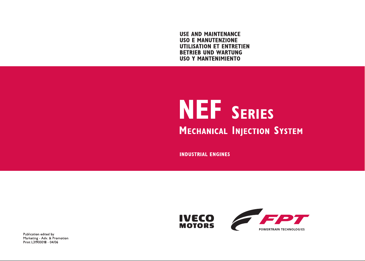
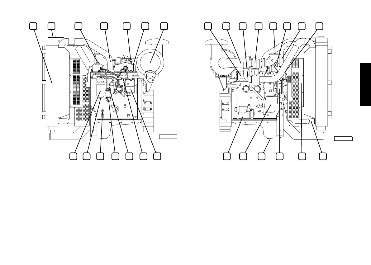
05_591_N
Engine N45 MNA - N45 MSA
1. Auxiliary member drive belt - 2. Fuel filter - 3. Oil filler cap - 4.
Fuel outlet connector to tank - 5. Engine air inlet - 6. Lifting U-bolt
- 7. Injection pump - 8. Cold injection timing variator - 9. Fuel inlet
manifold from tank - 10. Fuel supply pump - 11. Oil drainage plug -
12. Oil dipstick - 13. Fuel filter condensation drainage plug.
05_592_N
Engine N45 MNA - N45 MSA
1. Exhaust manifold - 2. Oil vapour bleeder - 3. Exhaust outlet -
4. Lifting U-bolt - 5. Engine coolant outlet - 6. Location of
thermostat valve - 7. Alternator - 8. Engine coolant inlet - 9.
Lubricant oil filter - 10. Electrical starter motor.
5
Page 7

ENGINE TECHNICAL DATA N45 MNS/MSS/MNT/MST
The technical code and serial number are indicated on a plate, which
is located on different parts of the engine, according to the model:
flywheel casing, tappet cover, other.
Code N45 MNS/MSS/MNT/MST
Engine family F4
Cycle 4-stroke diesel
Number and arrangement
of cylinders 4, in line
Bore x stroke 104 x 132 mm
Total displacement 4,500 cm
Air system Supercharged - Aftercooled
Injection type Direct with rotating pump
Engine direction of
rotation
Anticlockwise (seen from
flywheel side)
Dry weight 390 kg
(1) Excluding engines N45 MNS / MSS
3
(1)
Performance TIER2 Maximum power (*)
Maximum torque
N45 MNS / MSS 74 kW (100 CV) @ 2300 rpm
398 Nm (40.5 Kgm) @ 1400 rpm
N45 MNT / MST 82 kW (111 CV) @ 2200 rpm
480 Nm (48.9 Kgm) @ 1400 rpm
N45 MNT / MST 94 kW (128 CV) @ 2300 rpm
500 Nm (50.9 Kgm) @ 1400 rpm
Performance TIER3 Maximum power (*)
Maximum torque
N45 MNS / MSS 66 kW (89 CV) @ 2200 rpm
362 Nm (36.9 Kgm) @ 1400 rpm
N45 MNT / MST 74 kW (100 CV) @ 2200 rpm
397 Nm (40.5 Kgm) @ 1400 rpm
N45 MNT / MST 93 kW (126 CV) @ 2200 rpm
520 Nm (53 Kgm) @ 1400 rpm
(*)Net power to the flywheel in compliance with ISO 3046-1. Test
conditions: temperature 25 °C; atmospheric pressure 100 kPa;
relative humidity 30%.
Electrical system 12 V
Accumulator/s
- capacity
- discharge current
100 Ah or above
650 A or above
WARNING
Any alteration of the above mentioned characteristics is strictly
prohibited, penalty invalidation of the guarantee and absence of all
liability on the part of IVECO MOTORS.
6
Page 8
ENGLISH
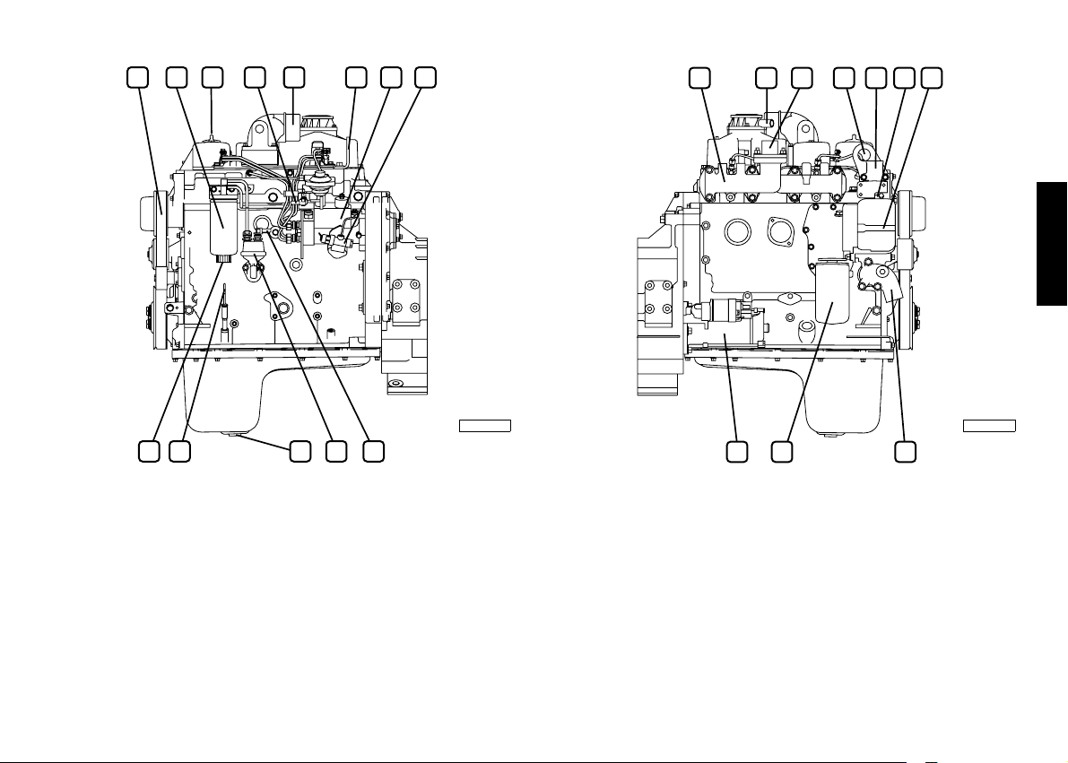
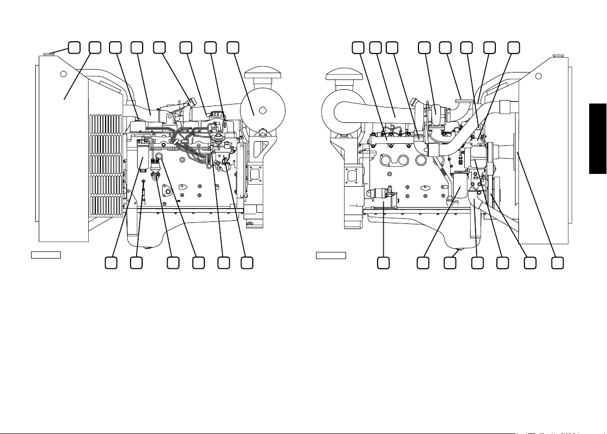
05_595_N
Engine N45 MNS/MSS/MNT/MST
1. Auxiliary member drive belt - 2. Fuel filter - 3. Oil filler cap - 4.
Fuel outlet connector to tank - 5. Oil vapour bleeder - 6. Lifting Ubolt - 7. Injection pump - 8. Cold injection timing variator - 9. Fuel
inlet manifold from tank - 10. Fuel pump - 11. Oil drainage plug -
12. Oil dipstick - 13. Fuel filter condensation drainage plug.
05_596_N
EngineN45 MNS/MSS/MNT/MST
1. Exhaust manifold - 2. Turbocharger air inlet - 3. Turbocharging air
outlet ( only for N45 MNT / MST engines) - 4. Turbocharger -
5. Turbocharger exhaust outlet - 6. Engine air inlet - 7. Lifting U-bolt
- 8. Engine coolant outlet - 9. Location of thermostat valve -
10. Alternator - 11. Engine coolant inlet - 12. Oil filter - 13. Electric
starter motor.
7
Page 9

ENGINE TECHNICAL DATA N67 MNA/MSA/MNT/MST
The technical code and serial number are indicated on a plate, which
is located on different parts of the engine, according to the model:
flywheel casing, tappet cover, other.
Code N67 MNA/MSA/MNT/MST
Engine family F4
Cycle 4-stroke diesel
Number and arrangement
of cylinders 6, in line
Bore x stroke 104 x 132 mm
Total displacement 6,700 cm
Air system Supercharged and aftercooled
Injection type Direct with rotating pump
Engine direction of rotation Anticlockwise (seen from flywheel
side)
Dry weight 530 kg
(1) Excluding engines N67 MNA / MSA
Electrical system 12 V
Accumulator/s
- capacity
- discharge current
180 Ah or above
950 A or above
3
(1)
Performance TIER2 Maximum power (*)
Maximum torque
N67 MNA / MSA 81 kW (110 CV) @ 2500 rpm
440 Nm (45 Kgm) @ 1400 rpm
N67 MNT / MST 120 kW (163 CV) @ 2300 rpm
630 Nm (64 Kgm) @ 1400 rpm
N67 MNT / MST 129 kW (175 CV) @ 2300 rpm
700 Nm (71 Kgm) @ 1400 rpm
Performance TIER3 Maximum power (*)
Maximum torque
N67 MNT 129 kW (175 CV) @ 2200 rpm
720 Nm (73 Kgm) @ 1400 rpm
(*)Net power to the flywheel in compliance with ISO 3046-1. Test
conditions: temperature 25 °C; atmospheric pressure 100 kPa;
relative humidity 30%.
WARNING
Any alteration of the above mentioned characteristics is strictly
prohibited, penalty invalidation of the guarantee and absence of all
liability on the part of IVECO MOTORS.
8
Page 10
ENGLISH
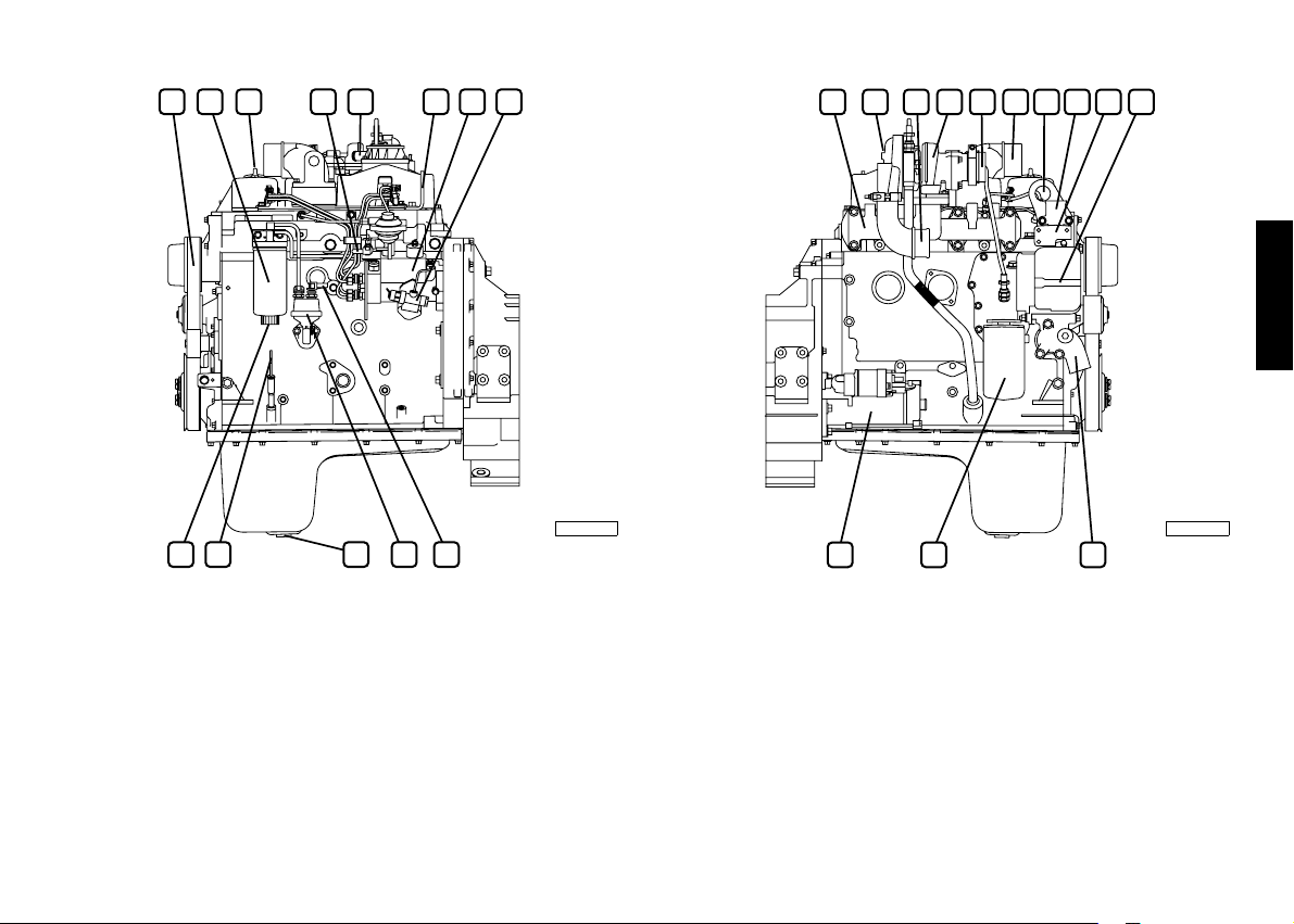
05_597_N
Engine N67 MNA/MSA - N67 MNT/MST
1. Auxiliary member drive belt - 2. Fuel filter - 3. Oil filler cap - 4.
Engine intake manifold - 5. Fuel outlet connector to tank - 6. Lifting
U-bolt - 7. Injection pump - 8. Cold injection timing variator -
9. Fuel inlet manifold from tank - 10. Fuel supply pump - 11. Oil
drainage plug - 12. Oil dipstick - 13. Fuel filter condensation drainage
plug.
05_598_N
EngineN67 MNA/MSA - N67 MNT/MST
1. Exhaust manifold - 2. Oil vapour bleeder - 3. Turbocharger air
inlet - 4. Turbocharging air outlet (*) - 5. Turbocharger (*) - 6.
Turbocharger exhaust outlet (*) - 7. Lifting U-bolt - 8. Engine
coolant outlet - 9. Location of thermostat valve - 10. Alternator -
11. Engine coolant inlet - 12. Lubricant oil filter - 13. Electrical
starter motor.
(*) Only for versions MNT/MST
9
Page 11

ENGINE TECHNICAL DATA NEF 45 SM - TM
The technical code and serial number are indicated on a plate, which
is located on different parts of the engine, according to the model:
flywheel casing, tappet cover, other.
Code NEF 45 SM1/SM2 - TM1/TM2
Engine family F4
Cycle 4-stroke diesel
Number and arrangement
of cylinders 4, in line
Bore x stroke 104 x 132 mm
Total displacement 4,500 cm
Air system Supercharged - Aftercooled
Injection type Direct with rotating pump
Engine direction of
rotation
Anticlockwise (seen from
flywheel side)
Speed regulator Mechanical
Dry weight 500 kg
1) Excluding versions SM
Electrical system 12 V
Accumulator/s
- capacity
- discharge current
100 Ah or above
650 A or above
3
(1)
Performance
(*)
NEF 45 SM1
(50 Hz) Prime 53.5 kWm @ 1500 rpm
Stand by 59 kWm @ 1500 rpm
(60 Hz) Prime 59
kWm @ 1800 rpm
Stand by 65 kWm @ 1800 rpm
Performance
(50 Hz) Prime 66
(*)
NEF 45 SM2
kWm @ 1500 rpm
Stand by 73 kWm @ 1500 rpm
(60 Hz) Prime 65
kWm @ 1800 rpm
Stand by 72 kWm @ 1800 rpm
Performance
(*)
NEF 45 TM1
(50 Hz) Prime 77 kWm @ 1500 rpm
Stand by 85 kWm @ 1500 rpm
(60 Hz) Prime 86
kWm @ 1800 rpm
Stand by 95 kWm @ 1800 rpm
Performance
(50 Hz) Prime 88
(*)
NEF 45 TM2
kWm @ 1500 rpm
Stand by 97 kWm @ 1500 rpm
(60 Hz) Prime 98
kWm @ 1800 rpm
Stand by 107 kWm @ 1800 rpm
(*)Values in compliancewith ISO 8528.
WARNING
Any alteration of the above mentioned characteristics is strictly prohibited,
penalty invalidation of the guarantee and absence of all liability on the
part of IVECO MOTORS.
10
Page 12
ENGLISH
05_611_N
Engine NEF 45 SM - TM
1. Heat exchanger/s - 2. Coolant filler cap - 3. Oil filler cap - 4.
Engine air inlet manifold - 5. Oil vapour bleeder - 6. Lifting U-bolt -
7. Air filter - 8. Injection pump - 9. Fuel outlet connector to tank -
10. Fuel inlet manifold from tank - 11. Hand pump - 12. Oil dipstick
- 13. Fuel filter condensation drainage plug - 14. Fuel filter.
*) Excluding versions SM
05_612_N
EngineNEF 45 SM - TM
1. Exhaust manifold - 2. Turbocharger air intake - 3. Turbocharging
air outlet - 4. Turbocharger- 5. Exhaust outlet - 6. Lifting U-bolt -
7. Coolant outlet manifold from engine - 8. Location of thermostat
valve - 9. Engine coolant inlet connector sleeve - 10. Fan -
11. Alternator - 12. Lubricant oil discharge plug - 13. Oil filter -
14. Electrical starter motor.
*) Excluding versions SM
11
Page 13

ENGINE TECHNICAL DATA NEF 67 SM - TM
The technical code and serial number are indicated on a plate, which
is located on different parts of the engine, according to the model:
flywheel casing, tappet cover, other.
Code NEF 67 SM1 - TM2/TM3
Engine family F4
Cycle 4-stroke diesel
Number and arrangement
of cylinders 6, in line
Bore x stroke 104 x 132 mm
Total displacement 6,700 cm
Air system Supercharged - Aftercooled
Injection type Direct with rotating pump
Engine direction of
rotation
Anticlockwise (seen from
flywheel side)
Speed regulator Mechanical
Dry weight 530 kg
1) Excluding versions SM
Electrical system 12 V
Accumulator/s
- capacity
- discharge current
180 Ah or above
950 A or above
3
(1)
Performance
(*)
NEF 67 SM1
(50 Hz) Prime 110 kWm @ 1500 rpm
Stand by 121 kWm @ 1500 rpm
(60 Hz) Prime 126 kWm @ 1800 rpm
Performance
Stand by 138
(*)
NEF 67 TM2
kWm @ 1800 rpm
(50 Hz) Prime 114 kWm @ 1500 rpm
Stand by 125 kWm @ 1500 rpm
(60 Hz) Prime 127 kWm @ 1800 rpm
Stand by 140 kWm @ 1800 rpm
Performance
(*)
NEF 67 TM3
(50 Hz) Prime 138 kWm @ 1500 rpm
Stand by 152 kWm @ 1500 rpm
(60 Hz) Prime 150 kWm @ 1800 rpm
Stand by 165 kWm @ 1800 rpm
(*)Values in compliance with ISO 8528.
WARNING
Any alteration of the above mentioned characteristics is strictly
prohibited, penalty invalidation of the guarantee and absence of all
liability on the part of IVECO MOTORS.
12
Page 14
ENGLISH
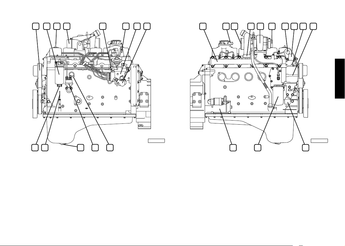
05_605_N
Engine NEF 67 SM - TM
1. Coolant filler cap - 2. Heat exchanger - 3. Lubricant oil filler cap
- 4. Engine air inlet manifold - 5. Waste-gate - 6. Oil vapour bleeder
- 7. Lifting U-bolt - 8. Air filter - 9. Injection pump - 10. Fuel outlet
connector to tank - 11. Fuel inlet manifold from tank - 12. Hand
pump - 13. Oil dipstick - 14. Fuel filter.
*) Excluding versions SM
05_606_N
EngineNEF 67 SM - TM
1. Exhaust manifold - 2. Turbocharger air intake - 3. Turbocharging air
outlet - 4. Turbocharger - 5. Exhaust gas discharge - 6. Lifting U-bolt
- 7.Coolant outlet manifold from engine - 8. Thermostat valve
location - 9. Fan - 10. Auxiliary member drive belt - 11. Alternator -
12. Engine coolant inlet sleeve - 13. Lubricant oil discharge plug - 14.
Oil filter - 15.Electrical starter motor.
*) Excluding versions SM
13
Page 15

SIGNS
Certain warning signs are affixed to the engine by the Manufacturer,
and their meanings are indicated below
N.B. The signs with an exclamation mark on them underline a
potential danger.
Lifting point (engine only).
Fuel Cap
(on the fuel tank, if there is one).
Oil Cap.
Oil dipstick.
Danger of burning:
Expulsion of hot water under pressure.
Danger of burning:
Presence of high temperature parts.
Danger of fire:
Fuel present.
Danger of impact or catching
on moving parts:
Presence of fans, pulleys, belts or the like.
14
Page 16

USE
PRELIMINARY CHECKS
Before starting the engine each time:
Check the level of technical fluids (fuel, engine oil and coolant),
and top-up if necessary.
Make sure that the air aspiration filter is not blocked or
obstructed, checking at the same time that the mechanical
indicator on the filter does not show the “red” sign. If the engine
is equipped with an electrical blockage sensor, an alarm will be
displayed on start-up, by means of the indicator light on the
instrument panel.
Note: The procedures required to clean the filter are indicated
in the chapter CONTROLS AND MAINTENANCE.
CAUTION!
Make sure that no combustible vapours or gasses are
present in the area in which the engine is to operate.
Ensure that closed areas are adequately ventilated and
fitted with a suitable exhaust extraction system.
STARTING AND STOPPING THE ENGINE
The start-up and shut-down operations described below apply to an
on-board control panel manufactured by IVECO MOTORS; if the
Manufacturer of the vehicle or machine has fitted a customised
instrument panel, these operations may vary according to the
various choices made during construction.
In these cases, follow the start-up/shut-down sequences and use the
instrument panel description provided in the specific
documentation.
ENGLISH
15
Page 17

Starting the engine from the IVECO MOTORS
control panel
1. Insert the key into the switch (1) and turn it to the right to
position 1B. “Run”. Once the indicator lights have been tested
and the beeper has stopped sounding, make sure that the
analogue instruments are showing values that conform with the
relevant physical parameters of temperature, battery voltage and
oil pressure; (information on how to interpret the indicators and
alarms is given in the relevant paragraph).
2. If the engine is fitted with a pre-heating system (optional) and the
engine temperature is lower than the minimum value foreseen
for it to come into operation, wait for the relevant indicator light
to go out.
3. Turn the key to position 1C “Start” and release it once the
engine has started, without accelerating.
4. Make sure that the “Battery recharge” and “Oil pressure low”
indicators have turned off and that the analogue instruments are
showing values that conform with the relevant new physical
parameters. If the pre-heating system has intervened, the
relevant indicator will turn on again to indicate that the postheating phase is in progress; the duration of this function is
proportional to the temperature value.
5. If the engine does not start, after releasing the key it will only be
possible to turn it back to the start position after first returning
the switch to the rest position 1A.
5
4
6
7
123
05_607_N
1. Key switch to start/stop the engine - 2. Beeper - 3. Voltmeter -
4. Rev counter and hour counter - 5. Coolant temperature
indicator - 6. Engine oil pressure indicator - 7. Alarm and indicator
module.
1A
Detail of the
1B
1C
key switch
05_580_N
1A “REST” position allowing the key to be removed
1B Stable “RUN” position
1C Unstable “START” position
STOP Unstable position used in EXCITED STOP set-ups for
engines fuelled by a mechanical injection pump.
16
Page 18

Start-up of a power generator
The start-up method described above may vary, depending on the
solutions used to create the electric panels and the system control
and running boards; so you should always comply with the
indications provided by the Fitter of the power generating plants or
the Manufacturer of the machine, even if the panels and control
stations have been created using the same components used for
IVECO MOTORS panels.
In any case, after start-up the engine will automatically revert to the
selected running speed.
It is suggested that the engine be warmed up with a reduced load
before applying the full load (*).
(*) With the exception of the emergency power generators, for
which the operating limits indicated in the commercial
documentation apply and for which the use of a pre-heating
device is required (see following pages).
Stopping the engine from the IVECO MOTORS
control panel
Before stopping the engine it is recommended you run it for a few
minutes at minimum speed with no load; this will allow the
temperature to drop evenly and will avoid harmful thermal shocks.
The shutdown method will depend on the type of equipment
installed.
With “unexcited” stop circuit
- Turn the key switch to position 1A - REST.
With “excited” stop circuit
- Turn the key switch to the STOP position.
In the absence of IVECO MOTORS control panels, always follow
the instructions provided by the Manufacturer of the machine.
ENGLISH
CAUTION!
The emergency power generator may start up at any time.
During maintenance operations it is therefore essential
that all the safety precautions set down by the
Manufacturer of the generator or the Preparer of the
system in which it is fitted be closely followed.
Should you intend to re-start the engine:
1. Return the key switch to the rest position 1A, thus resetting all
the on-board panel functions (Required for electronically
controlled engines).
2. Turn the key to position 1C “Start” and release it once the
engine has started, without accelerating.
3.Proceed as described previously.
17
Page 19

RECOGNISING ALARMS
Indicator and alarm synoptics
The IVECO MOTORS instrument panel contains the indicator lights
used to indicate the state of operation of the engine. Light-up of
these indicators is piloted by electronic circuits, which have a
simultaneous alarm timer and storage function.
7D
7C
7B
7A 7H
7A. Maximum allowed rotation speed exceeded (on request) - 7B.
Air filter blocked - 7C. Fuel level low - 7D. Coolant temperature
high - 7E. Oil pressure low - 7F. Alternator malfunction - 7G. Engine
coolant level low - 7H. Pre-post heating.
Some types of engine and relevant equipment only make some of
the functions indicated in the key available.
If the machine Manufacturer uses different technical options there
may also be further changes to the above.
7E
7F
7G
05_581_N
Operation
When the key is turned in the switch to position 1B an efficiency
test is performed, for 5 seconds, on all the indicator lights, with the
exception of the “Pre-post heating” indicator, while at the same
time the beeper sounds.
During start-up and for the following 15 seconds, all synoptic
functions are disabled; after this period, each critical state detected
by the sensors provided on the engine will result in the relevant
indicator lighting up.
Some alarms, which are of critical importance for efficient running
of the engine, will not only light the relevant optical indicator, but
will also start the beeper and cause automatic shutdown of the
engine:
- Maximum allowed rotation speed exceeded
- Coolant temperature high
- Oil pressure low
- Engine coolant level low.
CAUTION!
In the event of momentary stoppages of the engine, pay
attention to the synoptics and check for any alarm signals.
Do not restart the engine until the cause of the problem
has been removed or proper operating conditions have
been restored.
18
Page 20

ENGINE PRE-HEATING (optional)
(220 V, single phase electrical device)
The engines for which low temperature start-up and immediate
delivery of power are required may be fitted with a 220 V single
phase electrical heating device, which allows the temperature of the
coolant to be raised to or maintained at suitable values. The device
is fitted with a thermostat to cut the power supply when the
required temperature is reached.
FOR PROPER USE OF THE ENGINE
(with the exception of power generator engines)
Do not leave the key turned to the start position
engine has started.
It is not efficient to leave the engine running at minimum speed
while waiting for it to reach the proper working temperature; it
is preferable that, after approximately one minute from start-up,
you gradually increase the engine load.
Do not leave the engine running at minimum speed for long, as
this increases the production of harmful emissions and does not
guarantee the best performance.
The engine speed must be increased and decreased gradually, to
allow regular combustion and proper operation of all engine
components.
The running speed and power values must comply with the
specifications on the technical and commercial documentation.
During use, periodically check that:
1. The engine coolant temperature does not reach the alarm
threshold.
2. The oil pressure remains within normal values.
If the temperature is considered too high, reduce speed and stop to
check the state of the cooling system circuits; also check and have
checked:
a) the tension of the auxiliary member drive belt;
b) operation of the thermostat valve;
c) whether or not the heat exchanger is clean.
1C, when the
ENGLISH
19
Page 21

SPECIAL WARNINGS
Coolant circuit
When a state of “Coolant temperature high” and “Engine coolant
level low” is found, this triggers stoppage of the engine; in these
cases, check the efficiency of the circuit components, remembering
that when the engine is warm, a pressure liable to cause hot liquid
to be expelled with extreme violence is created within the cooling
circuits. This results in a danger of burning.
CAUTION!
Only open the coolant tank cap if strictly necessary, and
only when the engine is cold.
Lubrication circuit
When a state of “Oil pressure low”, is found, this triggers stoppage
of the engine; in this case, check the oil level and top up if necessary,
following the instructions given in the chapter on CONTROLS
AND MAINTENANCE.
If the condition persists, contact an Authorised Service Centre.
Fuel circuit
Avoid using the engine with only a small reserve of fuel in the fuel
tank; this encourages the formation of condensation and makes it
more likely you will suck up dirt or air, resulting in engine stoppage.
CAUTION!
When refuelling, always pay great care to ensure that no
solid or liquid pollutants enter the fuel tank; you must also
remember that smoking and live flames are prohibited
when refuelling.
CAUTION!
Never loosen the circuit connectors in any way when the
engine is running.
Air intake and exhaust discharge circuits
Inspect the cleanliness of the air intake circuit on a regular basis. The
maintenance intervals indicated in this manual vary according to the
conditions in which the engine is used.
In particularly dusty environments it is necessary to carry out
maintenance at more frequent intervals; with respect to the
indications provided in the chapter CONTROLS AND
MAINTENANCE.
20
Page 22

CAUTION!
Visually check that the exhaust circuit is not blocked or
damaged, so as to prevent dangerous fumes.
Electrical recharging and start-up system
Periodically check, particularly during the winter, to ensure that the
batteries are clean and in full working order, checking and topping
up as indicated in the chapter CONTROLS AND MAINTENANCE
Should it be necessary to replace the batteries, always respect the
capacity and minimum discharge current intensity requirements.
CAUTION!
The batteries contain an acid solution that will burn the
skin and corrode clothing; when checking them, always
wear protective clothing, gloves and goggles, do not smoke
or use live flames in the vicinity, and make sure that the
room they are housed in is adequately ventilated.
Periodically check or have someone check the cleanliness, wear and
full tensioning of the drive belt.
RUNNING IN
Thanks to modern engine construction technology, no particular
running in procedure is required. However, it is recommended that,
for the first 50 hours, you do not use the engine at high power for
long periods.
ENGLISH
21
Page 23

REFUELLING
Parts to be supplied N45 ...
NEF 45 ...
litres (kg)
Cooling circuit
Lubrication circuit
total capacity
(1)
(2)
(3)
12,8 (11,8)
N67 ...
NEF 67 ...
litres (kg)
8,5 10,5
17,2 (15,8)
Oil consumption is considered acceptable when it reaches a
maximum of 0.5% of fuel consumption
(3)The amounts indicated refer to initial refuelling, and include filling
the engine, sump and filter.
(4)Only use normal commercial diesel fuel (EN590 standards). Do
not use additives. Do not use fuels derived from the synthesis of
organic substances and vegetable oils (Biodiesel).
WARNING
Periodic changing:
oil sump at minimum level
oil sump at maximum level
Fuel tank
(4)
7 (6,5)
11,5 (10,5)
- -
8,7 (8)
15,2 (14)
NOTE: the amounts indicated relate to the standard configuration
of the engine only.
(I) Use a mixture of water and 50% PARAFLU 11 even during the
summer months. As an alternative to PARAFLU 11, use another
product that complies with international specifications SAE J
1034.
(2) Use lubricants that comply with international specifications
ACEA E3 - E5 (high power engines), API CF - CH4 (associated
with fuels with a percentage sulphur < 0.5%), MIL - L - 2104 F.
The viscosity level of oil to be used depending on surrounding
temperatures in given in the table provided in the appendix.
Refuelling from drums or tanks may result in pollution of the diesel
fuel, with the risk of damage to the injection system; if necessary, filter
the fuel in a suitable manner or allow sedimentation of the impurities
before refuelling.
Low temperature diesel
EN590 specifications distinguish different classes of diesel fuel,
identifying the characteristics of those best suited to low
temperatures.
It is entirely up to the Oil companies to comply with these
regulations, which foresee that fuels suited to the climactic and
geographic conditions of the various Countries be distributed.
22
Page 24

CONTROLS AND MAINTENANCE
MAINTENANCE PERSONNEL
The engine control and maintenance operations described in the
following chapter require training, experience and compliance with
current safety regulations; for this reason they must be carried out
by special technicians, as indicated below.
Controls: by workshop technicians or the machine user if
necessary.
Periodic maintenance: by qualified personnel
equipped with suitable equipment and adequate
means of protection. Operations marked by the key
symbol.
Special maintenance: by qualified Authorised
Service Centre staff with specific technical information
and equipment. Operations marked by the key
symbol.
The Authorised Service Centres are the ones in the IVECO
MOTORS Technical Service Network.
ACCIDENT PREVENTION
Always wear heavy-duty footwear and overalls.
Never wear loose, flapping garments, rings, bracelets and/or
necklaces in the vicinity of engines or moving parts.
Always wear protective gloves and goggles when:
• filling up batteries with acid solution
• refuelling with inhibitors or antifreeze
• replacing or topping up lubricant (hot engine oil may cause burns
and scalds. Only carry out these operations when the oil has
dropped to a temperature of below 50°C).
When working in the engine compartment, pay particular
attention to how you move, to avoid contact with moving parts
or high temperature components.
Wear goggles and use high pressure air jets (maximum air
pressure used to clean is 200 kPa (2 bar, 30 psi, 2 kg/cm
Wear a protective helmet when working in an area were there
are suspended loads or systems installed at head-height.
Use protective hand creams.
Immediately replace wet overalls.
Always keep the engine clean, removing oil, grease and coolant
stains.
Store cloths in flame-proof containers.
Do not leave foreign bodies on the engine.
Use suitable, safe containers for used oil.
When completing a repair, make suitable provisions to stop the
engine taking in air if, after start-up, an uncontrolled increase in
engine speed were to occur.
2
).
ENGLISH
23
Page 25

CAUTION!
Do not carry out maintenance operations when the electric
power supply is turned on: always check to ensure that the
appliances are properly earthed. During diagnosis and
maintenance operations, make sure that your hands and feet
are dry, and whenever possible use insulating stands
.
FREQUENCY
Controls (when in use) Frequency
Check oil level in engine Daily
Check coolant level Daily
Clean heat exchangers Daily
Clean air filter Daily
Drain water from the fuel pre-filter 150 hours
Check/top up electrolyte level
in batteries and clean terminals
Half-yearly
The maintenance intervals indicated below take into account the
typical working factors for various types of engine use; the most
suitable interval for maintenance operations for the various
applications will be indicated by the maintenance staff, according to the
way and working conditions in which the engine is used.
(1)
Planned maintenance
Check state and tension of belt 300 hours
Change oil 600 hours
Change oil filter/s 600 hours
Change fuel filter/s 600 hours
Change fuel pre-filter 600 hours
Frequency
(2)
(3) (4)
(3) (4) (5)
(3) (1) (5)
(3) (1)
Check exhaust pipe/s for damage Half-yearly
Drain/suck water and condensation
from fuel tank Half-yearly
(1)
Change auxiliary member belt 1200 hours
Change air filter 1200 hours
Change coolant 1200 hours or 2
years
(6)
24
Page 26

Special maintenance
Frequency
6) The frequency with which operations are carried out will depend
on the working conditions and efficiency/wear of the product.
7) Required by oil vapour recirculation.
Clean the turbocharger 1200 hours
Check the efficiency of the pre-post
1200 hours
(7)
heating system (if there is one)
Injector calibration 1800 hours
Overhaul injection pump 3000 hours
Adjust play in valves-rocker arms 3000 hours
1) Maximum period when using good quality fuel, (EN 590 standard);
this is reduced if the fuel is contaminated and alarms are triggered
due to blockage of the filters and presence of water in the prefilter. When blockage of the filter is indicated, it must be replaced.
If the water in pre-filter indicator does not go out after drainage,
the pre-filter must be replaced.
2) Refers to engines with traditional and automatic tensioning
devices
3) Must be performed annually, even if the required number of
working hours are not reached
4) Replace lubricants according to the frequency indicated in the
REFUELLING table.
5) Only use filters with the following characteristics:
- filtration level < 12 µm
- filtering efficiency ß > 200.
REQUIREMENTS
1. Do not disconnect the batteries with the engine running.
2. Do not carry out arc welding operations in the vicinity of the
engine without first removing electrical cables.
3. After each maintenance operation involving disconnection of the
battery/batteries, make sure that the terminals have been
properly locked onto the poles.
4. Do not use battery chargers to start the engine.
5. Disconnect the on-board network battery/batteries when
recharging.
6. Do not paint the appliances, components and electrical
connectors equipping the engine.
7. Disconnect the battery/batteries before any electrical
operations.
8. Contact the Manufacturer before installing electronic equipment
on board (two-way radios and the like).
ENGLISH
25
Page 27

HOW TO PROCEED
Check oil level in engine
Only proceed with the engine stopped and at a low temperature, so
as to avoid the risk of burning.
Take all necessary action to ensure that the machine is “level”.
Using the dipstick (1), check that the oil level is between the
"Min" and "Max" levels.
If the level is too low, top up through the inlet, after first
removing the relevant cap (2).
2
1
1
05_584_N
WARNING
After topping up, make sure that the oil level does not exceed the
"Max" limit marked on the dipstick.
Make sure that the dipstick is inserted properly and the filler cap
is turned in a clockwise direction until it stops turning completely.
05_608_N
26
Page 28

Check coolant level
Only proceed with the engine stopped and at a low temperature, so
as to avoid the risk of burning.
With the engine cold, make sure that the level of coolant in the
expansion tank is above the minimum level.
Visually check that the fluid level is not more than 2/3 of the
height of the tank, to allow the increase in temperature to
increase the volume of fluid.
Top up the tank if necessary, using clean water. Do not use
distilled water; indications are provided in the table
REFUELLING.
MAX
MIN
05_585_N
CAUTION
When the engine is warm, a pressure liable to cause hot
liquid to be expelled with extreme violence is created
within the cooling circuits. This results in a danger of
burning.
Clean heat exchangers
Check that the radiator air inlets are free from dirt (dust, mud,
straw, etc.).
Clean them if necessary, using compressed air or steam.
ENGLISH
05_609_N
CAUTION
The use of compressed air makes it necessary to use
suitable protective equipment for the hands, face and
eyes. Please see the prescriptions in the paragraph on
ACCIDENT PREVENTION.
27
Page 29

Cleaning the air filter
(Refers to IVECO MOTORS components)
Only proceed with the engine stopped.
Remove the filter cover (1) after first unscrewing the locking
handle.
Remove the external cartridge (2), after unfastening the second
locking handle; during this operation, take care to ensure that no
dust get into the sleeve.
Check that there is no dirt. If there is, clean the filter element as
indicated below.
Blow dehumidified compressed air through the filter element,
from the inside outward (maximum pressure 200 kPa). Do not
use detergents; do not use diesel.
Never use tools to beat the filter element, and check its
condition before replacing it.
Replace the filter if any breakages or tears are found.
Check that the gasket at its base is in good condition. Some filter
systems are fitted with a second filter element (3) which does not
require cleaning; this must be replaced at least once every 3
changes in the main element.
Reassemble by repeating the above operations in reverse order.
Set up the mechanical blockage indicator for operation by pressing
the button located on the top part of the indicator. This operation
is not necessary if there is an electrical sensor.
WARNING
Take care to ensure that the parts are reassembled correctly.
Imperfect assembly might result in unfiltered air being sucked into the
engine, causing serious damage.
05_590_N
1 2 3
28
Page 30

Drain water from the fuel pre-filter
The high risk of refuelling with fuel that is polluted by foreign bodies
and water makes it advisable to carry out this control every time
you refuel.
Proceed with the engine stopped.
Place a container under the filter or pre-filter to collect the fluid.
Unscrew the tap plug (1) in the bottom part of the filter; in some
lay-outs the plug includes a sensor to detect the presence of
water in the diesel.
Drain off liquid until only “diesel” can be seen.
Close the plug again, tightening it completely by hand.
Dispose of the drained fluids according to current requirements.
Visually check that the fluid level is between the “Min” and “Max”
limits; in the absence of references, check that the fluid covers
the Lead plates inside the elements.
Top up with distilled water only those elements in which the
level is below the minimum.
Contact specialised technical staff if the battery needs recharging.
Have the efficiency of the battery recharging system tested if
a voltage of less than 11 V (for 12 V rated systems) or 22 V
(for 24 V rated systems) is detected with the engine running.
On this occasion, make sure that the terminals and clamps are
clean, properly locked and protected by vaseline.
CAUTION
The batteries contain sulphuric acid, which is extremely
caustic and corrosive; always wear protective gloves and
goggles when topping them up. Whenever possible it is
recommended that this control be carried out by
specialised personnel.
Do not smoke or use live flames near the batteries
during the control, and make sure that the room you are
working in is adequately ventilated.
ENGLISH
1
Check/top up electrolyte level in batteries
Place the batteries on a level surface, then proceed as follows.
05_587_N
05_369_N
29
Page 31

04_362_N
Some types of battery havea single cover for all the inspection plugs.
To access the elements, use a lever as shown in the figure.
Restore the correct tension in the auxiliary
member drive belt
(Refers to engines with traditional tensioning devices)
Loosen the screw fixing the alternator to the bracket (1).
Loosen the bolt anchoring the alternator to its lower support.
Proceed to tighten the tensioner (2), locking the counternut.
On reaching the required tension, lock the fixing screws and bolt.
2
1
m
c
1
05_588_N
For engines without a screw tensioner, proceed after loosening the
fixing screws (1) and anchor bolt, turning the alternator as shown in
the figure until the required tension is reached, after which tighten
the fixing screws and anchor bolt firmly.
WARNING
Replace the belt if any abrasion, cracking or tearing is seen, and if oil
or fuel has spilled onto the belt.
30
Page 32
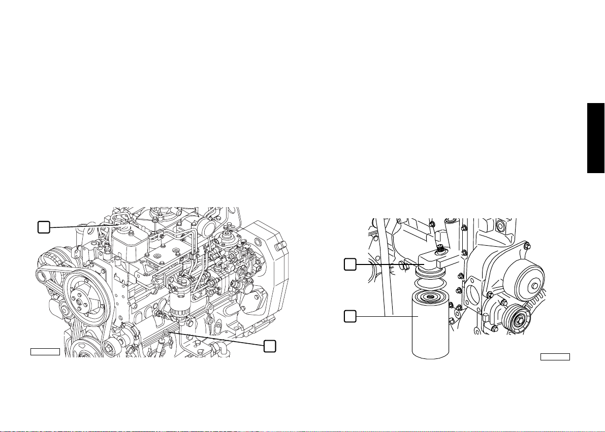
Change oil
Only proceed with the engine stopped and at a low temperature, so
as to avoid the risk of burning.
Place a container under the drainage plug to collect the used oil
(see illustrations in the chapter ENGINE TECHNICAL DATA).
Unscrew the plug and wait until the sump has emptied
completely, then fasten the plug in place again.
Fill up through the feeder hole (1) on the timer cover or
elsewhere (opt.), using the types and amounts of oil indicated in
the table REFUELLING.
Using the dipstick (2), check that the oil level is between the
"Min" and "Max" levels.
Dispose of used oil according to current requirements.
1
Change oil filter
Only proceed with the engine stopped and at a low temperature, so
as to avoid the risk of burning.
Only use filters with a filtration level equivalent to the ones you are
replacing (see section FREQUENCY).
Place a container under the filter support (1), to collect the used
oil.
Unscrew the filter and remove it (2).
Carefully clean the surfaces of the support that are in contact
with the seal gasket.
Damp the new seal gasket with a thin layer of oil.
Hand screw the new filter into place until the seal gasket touches
the support, then lock by a further 3/4 of a turn.
Dispose of the old filter according to current requirements.
1
2
ENGLISH
05_583_N
2
05_610_N
31
Page 33

Change fuel filter/s
Only proceed with the engine stopped and at a low temperature, so
as to avoid the risk of burning.
Only use filters with a filtration level equivalent to the ones you are
replacing (see section FREQUENCY).
Remove the filter/s by unscrewing it.
Check that the new filter has performance levels that satisfy the
needs of the engine (e.g. by comparing them with the old one).
Damp the new filter seal with diesel or engine oil.
Hand screw the new filter into place until the seal gasket touches
the support, then lock by a further 3/4 of a turn.
Pay particular attention to the electrical fuel pre-heater and
relevant electrical connection (1).
2
1
05_587_N
05_369_N
WARNING
Do not fill up the new filter before it is fitted to the support, to avoid
inserting harmful impurities into the injection system and circuit.
Bleeding procedure:
Loosen the fuel outlet manifold, located on the upper part of the
filter (2).
Make sure that any diesel coming out will not dirty the auxiliary
member drive belt or be dispersed into the environment.
Use the pre-filter hand pump until the diesel coming out is free
from any residual air or perform the same operation using the
mechanical feed pump (3).
Lock the manifold loosened as above to the required torque.
Dispose of any diesel expelled during the above operation in
accordance with the law.
Start the engine and run it at minimum speed for a few minutes
to eliminate any residual air.
NOTE: should it be necessary to
accelerate the bleeding phase,
the hand pump can be used
during start-up.
32
3
05_370_N
Page 34

Changing the fuel pre-filter
Only proceed with the engine stopped.
Should the filter be fitted with a
sensor to detect the presence of
water, remove the whole sensor
4
from its seat.
Remove the pre-filter by
unscrewing it.
Check that the new filter has
performance levels that satisfy
the needs of the engine (e.g. by
comparing them with the old
one).
Damp the new filter seal with
diesel or engine oil.
Hand screw the new filter into
place until the seal gasket
touches the support, then lock
by a further 3/4 of a turn.
Place the water presence sensor
in its seat, taking care to couple
3
the threads correctly.
Loosen the bleeder screw (2) on the pre-filter support and
activate the hand pump (1) until the supply circuit is full. Ensure
that any fuel coming out is not dispersed into the environment.
Lock the bleeder screw tightly.
Start the engine and run it at minimum speed for a few minutes
to eliminate any residual air.
1
2
0_018_V
Check the efficiency of the earthing connection of the filter
support.
NOTE: should it be necessary to accelerate the bleeding phase, the
hand pump can be used during start-up.
Check exhaust pipe/s for damage
Visually check that the exhaust system is not blocked or damaged.
Make sure that there is no risk of dangerous fumes within the
machine. Contact the Manufacturer if necessary.
ENGLISH
Change auxiliary member belt
Please refer to the information provided for checking the belt
tension.
Change coolant
Only proceed with the engine stopped and at a low temperature, so
as to avoid the risk of burning.
Provide suitable containers to ensure that no coolant is
dispersed into the environment.
Loosen the seal elements, remove the sleeves connecting the
engine circuit to the heat exchanger and wait until it has emptied
completely. When empty, repair the circuit making sure that the
sleeves are perfectly sealed.
Fill up the circuit as indicated in the table REFUELLING. Check
the fluid level as indicated in the respective paragraph herein.
Bleed the circuit after a limited period of operation, and top-up
if the level appears to be insufficient.
33
Page 35

WARNING
The operations listed below must only be carried out by qualified staff
from the IVECO MOTORS Service Centres or by the Manufacturer's
staff.
The methods used to perform them are described in the Technical
and Repair Manuals.
Drain/suck condensation from fuel tank
Clean the turbocharger
Check the efficiency of the pre-post heating system
Adjust play in valves-rocker arms
Injector calibration
Overhaul injection pump
MOVING THE ENGINE
The operations necessary to disconnect and subsequently
reconnect the engine must only be carried out by technicians from
Authorised Service Centres.
When lifting the engine only, use the U-bolts indicated in this manual
in the section ENGINE TECHNICAL DATA and marked on the
engine with special stickers.
Lifting must be carried out using a rocker arm that keeps the metal
cables supporting the engine parallel, using all the U-bolts provided
simultaneously; the use of a single U-bolt only is not allowed.
The engine lifting system must have a capacity and size suited to the
weight and dimensions of the engine; check that there is no
interference between the lifting system and the engine components.
Do not lift the engine before removing the transmission members
that are coupled to it.
DISPOSAL OF WASTE
The engine is made up of parts and elements that, if discarded, may
cause damage to the environment.
The materials listed below must be handed over to specialised
Collection Centres; the laws in force in the various Countries
foresee severe penalties for transgressors:
Starter batteries.
Used lubricants.
Mixtures of water and antifreeze.
Filters.
Additional cleaning materials (e.g. greasy or fuel-soaked cloths).
34
Page 36

LONG PERIODS OF INACTIVITY
PREPARING THE ENGINE FOR A LONG
PERIOD OF INACTIVITY
In order to prevent oxidation of the internal parts of the engine and
of certain components in the injection system, when the engine is
expected to be inoperative for periods of more than two months,
the following operations must be carried out in preparation for this:
1. Drain the lubricant from the sump, after first warming up the
engine.
2. Fill the engine with protective oil type 30/M (or alternatively oil
that complies with MIL 2160B type 2 specifications), up to the
"minimum" level indicated on the dipstick. Start the engine and
keep it running for approximately 5 minutes.
3. Drain the fuel from the injection circuit, from the filter and from
the injection pump pipes.
4. Connect the fuel circuit to a tank containing CFB (ISO 4113)
protective fluid, and feed in the fluid by putting the circuit under
pressure and running the engine for approximately 2 minutes,
after first disabling the injection system. This operation can be
performed by polarising terminal 50 of the starter motor with a
positive voltage equivalent to the rated voltage of the system,
using a conductor provided for that purpose.
5. Nebulise approximately 80 g of 30/M protective oil (10 g per litre
displacement) into the turbocharger suction inlet, during the
pressurised filling operation described in the previous point.
6. Close all the suction, delivery, ventilation and bleeder openings
in the engine with suitable plugs, or seal them with adhesive tape.
7. Drain the residual 30/M protective oil from the sump. This oil can
be used again for a further 2 preparation operations.
8. Fit signs reading "ENGINE WITHOUT OIL" to the engine and to
the on-board control panel.
9. Drain the coolant, if it has not been mixed with suitable
antifreeze and corrosion inhibitors, and affix a sign to indicate the
fact.
In the event of prolonged inactivity, the operations described must
be repeated every 6 months, following the procedure given below:
A) drain the 30/M protective oil from the sump;
B) repeat the operations described from point 2 to point 7.
Should you intend to protect external parts of the engine, proceed
by spraying OVER 19 AR protective liquid on unpainted metal parts,
such as the flywheel, pulleys and the like, avoiding belts, connector
cables and electrical equipment.
ENGLISH
35
Page 37

RESTARTING THE ENGINE AFTER A LONG
PERIOD OF INACTIVITY
1. Drain the residual 30/M protective oil from the sump.
2. Fill the engine, as prescribed, with lubricant of the type and
amount indicated in the table REFUELLING.
3. Drain the CFB protective fluid from the fuel circuit, carrying out
this operation as indicated under point 3. of PREPARING THE
ENGINE FOR A LONG PERIOD OF INACTIVITY.
4. Remove the plugs and/or seals from the suction, delivery,
ventilation and bleeder openings in the engine, restoring it to a
normal state of use. Connect the turbocharger suction inlet to
the air filter.
5. Connect the fuel circuits to the machine’s fuel tank, completing
the operations as indicated in point 4. of PREPARING THE
ENGINE FOR A LONG PERIOD OF INACTIVITY. During filling
operations, connect the fuel return pipe to a collection tank, so
as to prevent any residual CFB protective fluid from flowing into
the machine's fuel tank.
6. Check the engine and fill it up with coolant as prescribed,
bleeding it if necessary.
7. Start the engine and keep it running until the idling speed rate has
stabilised completely.
8. Check that the instruments on the on-board control panel/s are
showing plausible values, and that no alarms are shown.
9. Stop the engine.
10.Remove the "ENGINE WITHOUT OIL" signs from the engine
and from the on-board control panel.
36
Page 38

BEHAVIOUR IN AN EMERGENCY
The user of a machine that has been constructed according to safety
regulations, when following the instructions provided in this manual
and the indications given on the engine labels, will be working in safe
conditions.
Should improper conduct result in accidents, always request the
intervention of trained first aid specialists immediately.
In an emergency and while awaiting the arrival of first aid specialists,
follow the instructions given below.
Engine malfunctions
When operating with a malfunctioning engine, take the greatest
possible care when manouevering and make sure that all those
aboard are holding firmly to safe hand-holds (see section on
ENGINE MALFUNCTIONS)
In case of fire
Extinguish the fire using the fire-fighting equipment foreseen, and in
the manner indicated by Fire prevention authorities (fire-fighting
equipment for certain machines and equipment is compulsory under
current safety legislation).
Burns and scalds
1. Extinguish any flames on the burned person's clothing, by:
• throwing water over them;
• using a powder fire-extinguisher, without directing the jet at the
person's face;
• covering with blankets or rolling the victim on the ground.
2. Do not attempt to remove pieces of clothing that may have stuck
to the skin;
3. In the case of scalding, immediately but carefully remove any
clothing that may be soaked in the hot liquid;
4. Cover the burn with a special burn dressing or sterile bandage.
Carbon monoxide intoxication (CO)
Carbon monoxide from the engine exhaust is without smell, and is
dangerous both because it causes intoxication, and because when
combined with air it forms an explosive mixture.
In closed rooms, carbon monoxide is extremely dangerous, as it can
reach critical concentrations within a very short time.
When assisting an intoxicated person in a closed room:
1. Ventilate the room immediately, to reduce the concentration of
gas.
2. When entering the room, hold your breath, do not light flames,
lights or ring electric doorbells or phones, to avoid the risk of
explosion.
3. Carry the intoxicated person out into the fresh air or into a well
ventilated room, resting him on one side if he is unconscious.
ENGLISH
37
Page 39

Electrocution
A. The engine's electrical 12 V or 24 V electrical system does not
involve the risk of electrocution, however, in the event of a
short-circuit caused, for example, by a metal tool, there is a risk
of burning due to overheating of the object through which the
electrical current runs. In these circumstances:
1. Remove the object that caused the short-circuit, using means
that provide sufficient heat insulation.
2. Switch off the power at the main switch, if there is one.
B. The electric generator systems (generator units) normally
produce high voltages that are liable to result in extremely
dangerous current levels. In the event of medium or high voltage
electrocution:
1. Turn off the power supply at the main switch before touching the
victim. If this is not possible, use equipment that is both safe and
adequately insulated when touching the victim; remember that
touching a victim of electrocution is also extremely dangerous
for the person giving aid.
2. Proceed as indicated by the competent authorities (cardiac
massage, mouth-to-mouth resuscitation, etc...)
Injuries and fractures
The vast number of possible circumstances and the specific nature
of operations required means that the intervention of a medical
team is necessary.
1. In the event of bleeding, keep the edges of the wound pressed
together until help arrives.
2. If there is any suspicion of a fracture, do not move the injured
part and only move the patient if absolutely necessary.
Caustic burns
Caustic skin burns are caused by contact with extremely acid or
alkaline substances.
For electric maintenance technicians these are typically caused by
acid from batteries; in these circumstances, proceed as follows:
1. Remove any clothing soaked in the caustic substance.
2. Wash the area with lots of running water, avoiding parts that
have not been burned.
If either battery acid, lubricants or diesel come into contact with the
eyes: wash the eyes with water for at least 20 minutes, keeping the
eyelids open so that the water flows over the eyeball (move the eye
in all directions to wash more thoroughly).
38
Page 40

&
6$(:
6$(:
6$(
6$(
6$(:
6$(:
6$(:
6$(:
6$(:
6$(:
6$(:
6$(:
V\QWKHWLFEDVH
V\QWKHWLFEDVH
PLQHUDOEDVH
VHPLV\QWKHWLFEDVH
VHPLV\QWKHWLFEDVH
ENGLISH
39
)
Page 41

ELECTRONIC CONTROL PANEL USE REQUIREMENTS
The data indicated below refer to IVECO MOTORS equipment in its original configuration.
The requirements and technical characteristics of the customisations may differ from those indicated and must be dealt with in a specific
document prepared by those who have performed any such customisations.
IVECO MOTORS control panels With analogue instruments With digital instruments
Environmental working conditions
Operating temperature range from -10°C to +60°C from -10°C to +60°C
Temperature limits during stationing min. -20°C / max. +75°C min. -20°C / max. +75°C
Degree of protection against dusts and rain (front) IP 65 – DIN 40050 – IEC 529 IP 66
Saline mist resistance (Reference standard) IEC 60068-2-52 IEC 60068-2-52
Electric and electromagnetic characteristics
Operating voltage (excluding polarity inversions) min. 9 V / max. 32 V (*) min. 9 V / max. 32 V (*)
Maximum allowed overvoltage 60 V per 1 ms 60 V per 1 ms
Maximum allowed current on main control panel 1.1 A (12 V) – 1 A (24 V) 310 mA (12 V) – 200 mA (24 V)
Maximum allowed current on secondary control panel 400 mA (12 V) -400 mA (24 V) 310 mA (12 V) -200 mA (24 V)
Electromagnetic compatibility (Reference standard) IEC 945 IEC 945
Wiring connector requirements (Reference standard) MIL 1344/1001 MIL 1344/1001
Wiring requirements (Reference standard)
Mechanical characteristics
Vibration resistance (expressed as gravity acceleration)
Shock resistance (expressed as gravity acceleration) 15 g - 1.5 ms - semisinusoidal wave 15 g - 1.5 ms - semisinusoidal wave
CEI 20/22 - CEI 20/38 - CEI 2000/532/CE
1 g eff. max. -25-500 Hz 2 g eff. max. -25-500 Hz
(*) min. 9 V / max. 16 V referring to the equipment designed to be supplied only at the rated voltage of 12 V.
40
 Loading...