

Page 1

STRALIS AT/AD
REPAIR MANUAL
MECHANICAL
ELECTRIC
ELECTRONIC
Page 2

STRALIS AT/AD
REPAIR MANUAL
Page 3

This publication describes the characteristics, the data, the
correct methodology of the repairs that can be made on each
individual component of the vehicle.
By complying with the instructions supplied and using the
specific tools it is possible to perform any repair intervention
correctly, within the specifiedtime frames, while protecting the
technicians against incidents.
Before starting any repair work, make sure that all accident
prevention devices are ready at hand.
Check and wear the protective personal equipment provided
for by the safety standards: goggles, helmet, gloves, shoes.
Check the efficiency of all processing, lifting and transport tools
before using them.
The data contained in this publication might fail to reflect the
latest changes which the Manufacturer may introduce at any
time, for technical or sales purposes, or to meet the
requirements of local legislation.
Copy, even partial, of text and drawings is forbidden.
Publication Edited by:
IVECO S.p.A.
T.C.O. - B.U. Customer Service
Lungo Stura Lazio, 15/19
10156 Torino (Italy)
Printed 603.93.141 -1
st
Ed. 2003
Produced by:
B.U. TECHNICAL PUBLISHING
C.so Svizzera, 185
10149 Torino (Italy)
Page 4

SPECIAL REMARKS
The workshop manuals for mechanical parts have been divided into Sections, each of which has a number and its relevant contents
are indicated in the General Specifications. Each section features a main Unit (e.g. engine, gears etc.).
The subjects usually dealt with in each section are:
Technical data table, Driving torques, Equipment, Diagnostic, Removal and Fitting in place, Repair operations.
Where possible, the same sequence of procedures has been followed for easy reference.
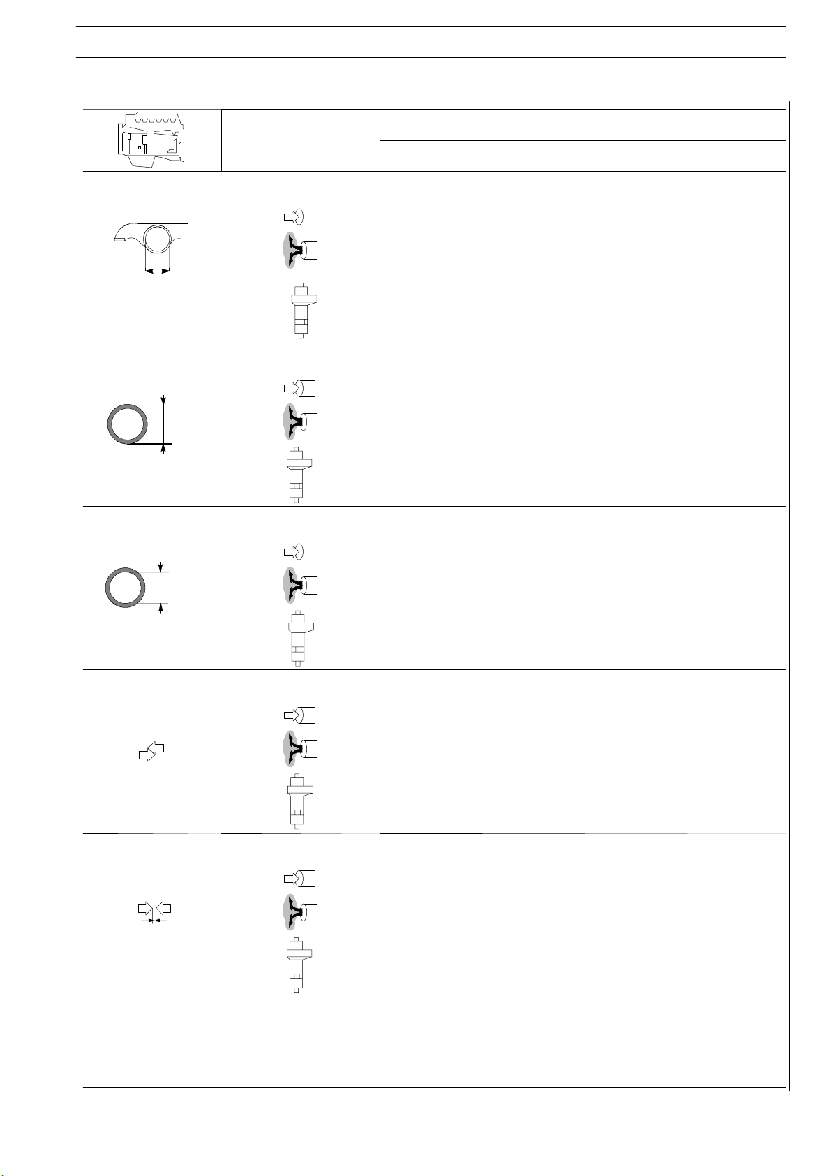
Diagrams and symbols have been widely used to give a clearer and more immediate illustration of the subject being dealt with, (see
next page) instead of giving descriptions of some operations or procedures.
Example
∅
Ø 1 = h ousing for connecting rod small end bush
1
Tighten to torque
Ø 2 = h ousing for connecting rod bearings
Tighten to torque +
α
angular value
∅2
Furthermore, within each section, every heading or sub-heading concerning the operations to be carried out is preceded by a six
digit number. This number is the Product Code that is to be found in the repair operation described in the REPAIR TIMES CHARTS
and in the FAULT CODES.
For quick reference the indication of how to read this code is described below (see the Repair time charts also).
Product Code:
50
PRODUCT UNIT SUB-ASSEMBLY
COMPONENT
Example:
Product 50 = Frame;
Product 52 = Axles;
Product 53 = Gears etc.
Unit Code:
PRODUCT UNIT SUB-ASSEMBLY
01
COMPONENT
Figures three and four identify the ASSEMBLY within the PRODUCT
Example:
Product 50 = Frame;
Unit 01 = Chassis;
Unit 02 = Bumpers etc .
Sub-assembly Code:
PRODUCT UNIT SUB-ASSEMBLY
40
COMPONENT
Example:
Product 50 = Frame;
Unit 01 = Chassis;
Sub-assembly 40 = Chassis cross members etc.
Print 603.93.141 Base - January 2003
Page 5
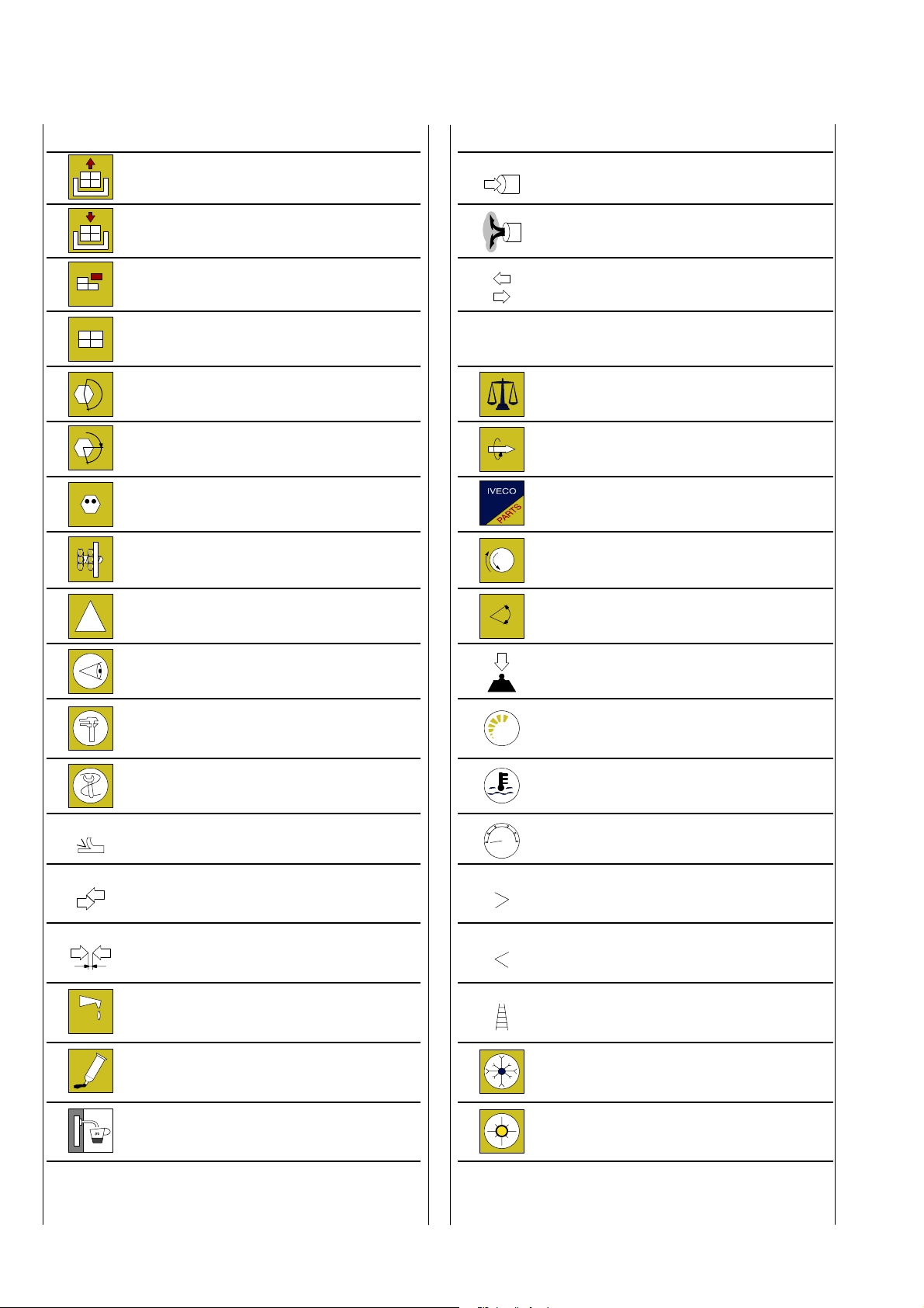
Graphs and symbols
Removal
Disconnection
Refitting
Connection
Removal
Disassembly
Fitting in place
Assembly
Tighten to torque
α
!
Tighten to torque + angle value Rolling torque
Press or caulk
Regulation
Adjustment
Warning
Note
ρ
Intake
Exhaust
Operation
Compression ratio
Tolerance
Weight difference
Replacement
Original spare parts
Rotation
Angle
Angular value
Visual inspection
Fitting position check
Measurement
Value to find
Check
Equipment Temperature
Surface for machining
Machine finish
Interference
Strained assembly
Thickness
Clearance
Lubrication
Damp
Grease
Sealant
Adhesive
Air bleeding
bar
Preload
Number of revolutions
Pressure
Oversized
Higher than….
Maximum, peak
Undersized
Less than….
Minimum
Selection
Classes
Oversizing
Temperature < 0°
Cold
Winter
Temperature > 0°
Hot
Summer
Base - January 2003 Print 603.93.141
Page 6

Print603.43.671/A
STRALIS AT/AD
Print 603.93.141 — 1stedition
Base — January 2003
UPDATE DATA
Section Description Page Revision date
Print 603.93.141 Base - January 2003
Page 7

Base - January 2003 Print 603.93.141
Page 8

INDEX OF SECTIONS
Section
General information
Engine 2
Clutch 3
Gearbox 4
Hydraulic retarder 5
Propeller shafts 6
Rear axles 7
Front axle 8
1
Front and rear suspensions 9
Wheels and tyres 10
Steering system 11
Pneumatic system - brakes 12
Bodywork and chassis frame 13
Maintenance 14
Print 603.93.141 Base - January 2003
Page 9

Base - January 2003 Print 603.93.141
Page 10

SECTION 1
General
VEHICLE IDENTIFICATION DATA 3..........
- Vehicle identification plate 4................
- Production identification plate 4.............
COMPOSITION OF MODELS 5..............
P.I.C. NUMBER CODING 9..................
REPLENISHING FLUIDS 13...................
1STRALIS AT/AD GENERAL
Page
Print 603.93.141 Base - January 2003
Page 11

2
GENERAL
STRALIS AT/AD
Base - January 2003 Print 603.93.141
Page 12
Print603.43.671
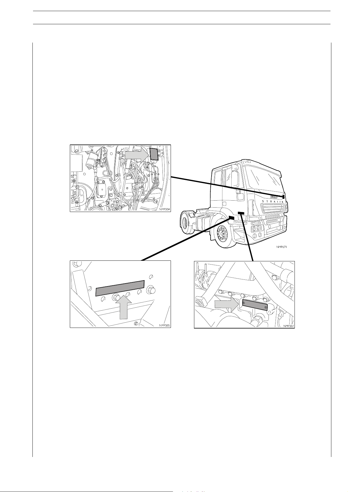
VEHICLE IDENTIFICATION DATA
The type and number of engine, type and
number of chassis and manufacturer’s plate
comprise the vehicle identification data.
3STRALIS AT/AD GENERAL
Manufacturer’s
plate
To identify the vehicle in accordance with the
E.E.C. directive
(under the front radiator cowling).
Chassis frame
Punching (front on right side member of
chassis frame).
Engine
Plate on the left rear side of the crankcase
Print 603.93.141 Base - January 2003
Page 13
4
GENERAL
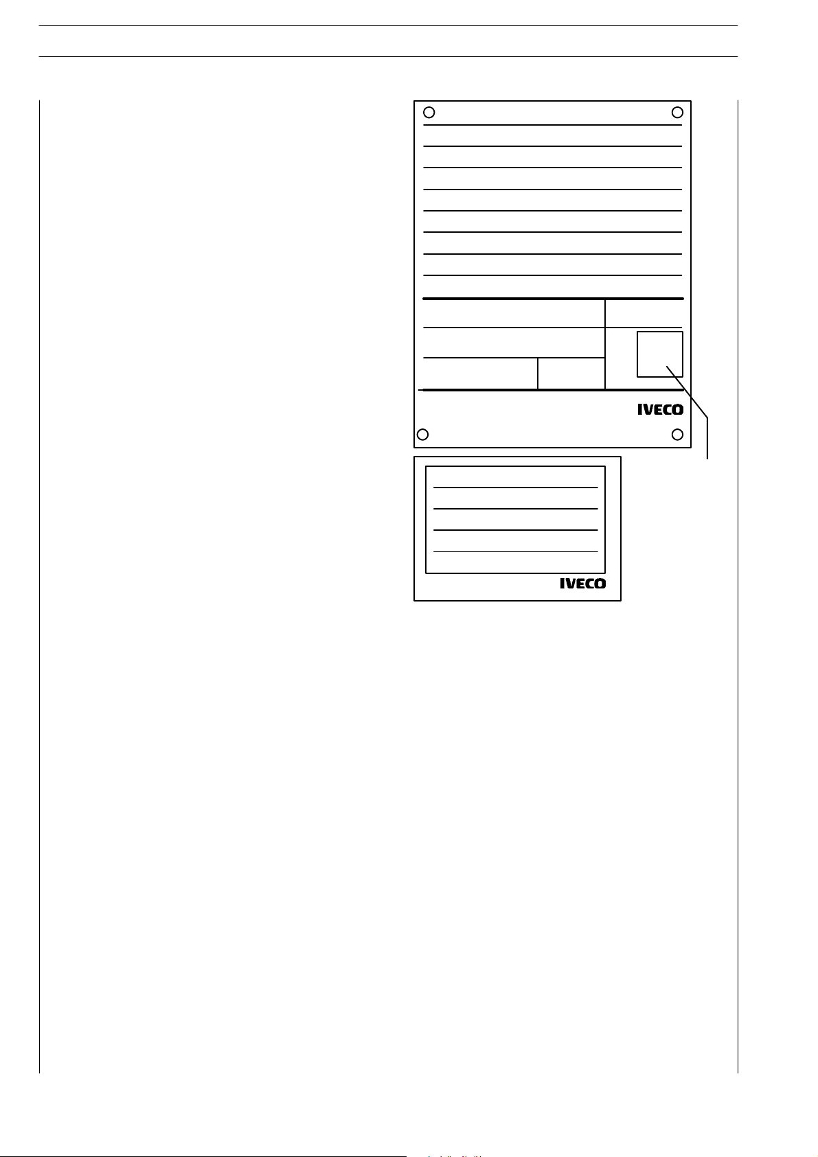
Vehicle Identification Plate
STRALIS AT/AD
Plate legend
a) Type-approval number marking (if applicable).
b) Vehicle identification code number (V.I.N.).
c) Total tractor weight.
d) Total weight of tractor + trailer (if applicable).
e) Permissible weight limit on 1st axle.
f) Permissible weight limit on 2nd axle (if applicable).
g) Permissible weight limit on 3rd axle.
h) Permissible weight limit on 4th axle (if applicable).
i) Specific identification of type.
l) Wheelbase in mm.
m) Engine type.
n) Engine power.
o) No. of axles.
p) Place of manufacture.
Production identification plate
This plate shows the P.I.C. (production identification code
number), which is needed when referring to the spare
parts catalogue (electronic and/or microfiche catalogue).
The P.I.C. is also given on the vehicle warranty card.
Note: When consulting the catalogues, use only the first
8 digits of the product identification code number.
a)
b)
c)
d)
e)
f)
g)
h)
i)
l)
m)
p)
IVECO MAGIRUS AG
1234-
Type
Wheelbase
Engine type
Made in
Unit No
Part No
Serial No
P.I.C. No
Made in Germany-Iveco Magirus AG
Engine power KW
n)
Noof axles
Corrected
absorption
value
Kg
Kg
Kg
Kg
Kg
Kg
o)
Permissible
grade of
smoke
9843 8247
Base - January 2003 Print 603.93.141
Page 14

COMPOSITION OF MODELS
5STRALIS AT/AD GENERAL
ASSEMBLIES
CHASSIS CABS - 4x2 MODELS
AD 190 S 27
AT 190 S 27
AD 190 S 27/P
AT 190 S 27/P
AD 190 S 27/FP-D
AT 190 S 27/FP-D
AD 190 S 30
AD 190 S 30/P
AD 190 S 31
AT 190 S S31
AD 190 S 31/P
AT 190 S 31/P
AD 190 S 31/FP-D
AT 190 S 31/FP-D
AD 190 S 35
AT 190 S 35
AD 190 S 35/P
AT 190 S 35/P
AD 190 S 35/FP-D
AT 190 S 35/FP-D
AD 190 S 40
AT 190 S 40
AD 190 S 40/P
AT 190 S 40/P
AD 190 S 40/FP-D
AT 190 S 40/FP-D
AT 190 S 40/FP-CT
AD 190 S 43
AT 190 S 43
AD 190 S 43/P
AT 190 S 43/P
AD 190 S 43/FP-D
AT 190 S 43/FP-D
F2BE0681F (270 CV)
F2BE0681E (300 CV)
F2BE0681B (310 CV)
f f f
fff
f
f
f
f f f f f
F2BE0681A (350 CV) f f f f f f
F3AE0681B (400 CV) f f f f f f f
F3AE0681D (430 CV) f f f f f f f
Single disc 16” f f f f f f f f f f f f f f f f f f f f
Single disc 17” f f f f f f f f f f f f f f
ZF 9 S 109 D.D. f f f f f f f f f f f f
ZF 16 S 151 D.D. f f f f f f
ZF 16 S 181 O.D.
ZF 16 S 181 D.D. f f f f f f f f f f f f f f
ZF 16 S 221 O.D.
EuroTronic Automated 12 AS 2301 O.D.
EuroTronic Automated 12 AS 2301 D.D. f f f f f f f f f f f f f f f f f f f f f f
Allison MD 3060 P - MD 3066 P f f f f
FRONT AXLE: 5876/4 (F 8021)
5876/5 (F 8021) F F F F F F F F F F F F F F
⊗ ⊗ ⊗ ⊗ ⊗ ⊗ ⊗ ⊗ ⊗
⊗ ⊗ ⊗ ⊗ ⊗ ⊗ ⊗ ⊗ ⊗ ⊗ ⊗ ⊗ ⊗ ⊗ ⊗
F
F F F F F F F F F
5886/5 (F 9021) f f f f f f f f f f
ADDED AXLE:
Steering central 5876/4 (F 8021)
Rigid rear 55080/D1 (N 8071) *
Rigid rear 56082/D1 (N 9171) *
Steering rear 57080/D1 (N 8072) *
MERITOR MS 13-175/T - MS 13-175/D
f f f f f f f f f f f
f f f f f f f f f f f f f f f f f f f f f f f
MERITOR RT 160/1
451391 HR
ZF 8098
FRONT MECHANICAL Front
f f f f f f f f f f f
j
j j
j
j j
j
j j j j j j f j j j j j j j j
f f f f f f f f f f f f f f f f f f f f f f f
Rear j j j j j j j j j j j
T=4x2tractor
TX = 6x2 C tractor (central added axle cannot
be lifted)
TY = 6x2 P tractor (rear added axle can be
lifted)
AT 190 S 43/FP-CT
TN = 6x2 vehicles with mechanical rear
suspensions and raisable rigid rear added
axle
TZ = 6x4 tractor (bogie rear axle)
P = 4x2 — 6x2P — 6x2C vehicles with air
suspension on rear axle and 6x2P vehicles
with rigid rear axle that can be lifted with
single wheels
PT = 6x2P vehicles with air suspension on rear
axle and rigid rear added axle that can be
lifted with twin wheels
PS = 6x2P vehicles with air suspension on rear
axle and on steering rear added axle that
can be lifted with single wheels
FP = 4x2 — 6x4 — 6x2P — 6x2C vehicles with
front and rear air suspensions
FS = 6x2P vehicles with front and rear air
suspensions, steering rear added axle can
be lifted with single wheels
4x2 = Vehicles with two axles with rear driving
axle
6x2P = Vehicleswith three axles with rear driving
axle and rear added third axle that can be
lifted
6x2C = Vehicleswith three axles with rear driving
axle and central added third axle that
cannot be lifted
6x4 = Vehicles with three axles with two rear
driving axles (in tandem)
CM = Movable Boxes
LT = Tractor with lowered chassis frame
CT = Chassis cab with lowered chassis frame
RR = Rough Roads
D=Distribution
HR = Hub Reduction
AT = Active Time
AD = Active Day
PNEUMATIC Front
Rear
f f f f f f f f f f f f
f f f f f f f f f f f f f f f f f f f f f f f
Added axle
⊗ = With brake calliper assembly at 57° without parking brake j = With parabolic leaf springs
F = With brake calliper assembly at 0° with parking brake * = TI with drum brakes
Z = With longitudinal and transversal bars
Print 603.93.141 Base - January 2003
Page 15

6
GENERAL
COMPOSITION OF MODELS
STRALIS AT/AD
ASSEMBLIES
CHASSIS CABS - 6x2 P MODELS
AD 260 S 27Y/P
AT 260 S 27Y/PS
AT 260 S 27Y/P
AD 260 S 27Y/PS
AD 260 S 27Y/FP-D
AT 260 S 27Y/FS-D
AT 260 S 27Y/FP-D
AD 260 S 27Y/FS-D
AT 260 S 30Y/FS-D
AD 260 S 31Y/P
AD 260 S 31Y/PS
AT 260 S 31Y/PS
AD 260 S 31Y/FP-D
AT 260 S 31Y/FP-D
AD 260 S 31Y/FS-D
AT 260 S 31Y/FS-D
AD 260 S 35Y/P
AD 260 S 30Y/PS
AT 260 S 30Y/PS
AT 260 S 31Y/P
AT 260 S 35Y/P
AD 260 S 35Y/FP-D
AD 260 S 35Y/PS
AT 260 S 35Y/PS
AT 260 S 35Y/FP-D
AD 260 S 35Y/FS-D
AT 260 S 35Y/FS-D
AD 260 S 27Y/PT
AT 260 S 27Y/PT
AD 260 S 27Y/TN
AT 260 S 31Y/PT
AT 260 S 27Y/TN
AD 260 S 31Y/PT
AD 260 S 31Y/TN
AT 260 S 31Y/TN
AD 260 S 35Y/PT
AT 260 S 35Y/PT
AD 260 S 35Y/TN
F2BE0681F (270 CV) f f f f f f f f f f f f
F2AE0681E (300 CV) f f f
F2BE0681B (310 CV) f f f f f f f f f f f f
F2BE0681A (350 CV) f f f f f f f f f f f f
F3AE0681B (400 CV)
F3AE0681D (430 CV)
Single disc 16” f f f f f f f f f f f f f f f f f f f f f f f f f f f f f f f f f f f f f f f
Single disc 17”
ZF 9S 109 D.D. f f f f f f f f f f f f f f f f f f f f f f f f f
ZF 16S 151 O.D. f f f f f f f f f f f f
ZF 16S 181 O.D.
ZF 16S 181 D.D.
ZF 16S 221 D.D.
EuroTronic Automated 12 AS 2301 D.D.
EuroTronic Automated 12 AS 2301 O.D. f f f f f f f f f f f f f f f f f f f f f f f f f f f f f f f f
Allison MD 3060 P - MD 3066 P f f f f f f f f f f f
FRONT AXLE: 5876/4 (F 8021) ⊗ ⊗ ⊗ ⊗ ⊗ ⊗ ⊗ ⊗ ⊗ ⊗ ⊗ ⊗ ⊗ ⊗ ⊗ ⊗ ⊗ ⊗ ⊗ ⊗ ⊗ ⊗ ⊗ ⊗ ⊗ ⊗ ⊗ ⊗ ⊗ ⊗ ⊗
5876/5 (F 8021) F F F F F F F F F F F F F F F F F F F F F F F F F F F F F F F
5886/5 (F 9021) f f f f f f f f
ADDED AXLE:
Steering central 5876/2 (F 8021)
Rigid rear 55080/D1 (N 8071) * f f f f f f f f f f f f
Rigid rear 56082/D1 (N 9171) * f f f f f f f f f f f f
Steering rear 57080/D1 (N 8072) * f f f f f f f f f f f f f f f
MERITOR MS 13-175/T - MS 13-175/D f f f f f f f f f f f f f f f f f f f f f f f f f f f f f f f f f f f f f f f
MERITOR RT 160/1
451391 HR
ZF 8098 f f f f f f f f f f f f f f f f f f f f f f f f f f f f f f f f f f f f f f
T=4x2tractor
TX = 6x2 C tractor (central added axle cannot
be lifted)
TY = 6x2 P tractor (rear added axle can be lifted)
TN = 6x2 vehicles with mechanical rear
AT 260 S 35Y/TN
suspensions and raisable rigid rear added
axle
TZ = 6x4 tractor (bogie rear axle)
P = 4x2 — 6x2P — 6x2C vehicles with air
suspension on rear axle and 6x2P vehicles
with rigid rear axle that can be lifted with
single wheels
PT = 6x2P vehicles with air suspension on rear
axle and rigid rear added axle that can be
lifted with twin wheels
PS = 6x2P vehicles with air suspension on rear
axle and on steering rear added axle that
can be lifted with single wheels
FP = 4x2 — 6x4 — 6x2P — 6x2C vehicles with
front and rear air suspensions
FS = 6x2P vehicles with front and rear air
suspensions, steering rear added axle can
be lifted with single wheels
4x2 = Vehicles with two axles with rear driving
axle
6x2P = Vehicles with three axles with rear driving
axle and rear added third axle that can be
lifted
6x2C = Vehicles with three axles with rear driving
axle and central added third axle that
cannot be lifted
6x4 = Vehicles with three axles with two rear
driving axles (in tandem)
CM = Movable Boxes
HM = Heavy Mission
LT = Tractor with lowered chassis frame
CT = Chassis cab with lowered chassis frame
RR = Rough Roads
D=Distribution
AT = Active Time
AD = Active Day
FRONT MECHANICAL Front j j j j j j j j j j j j j j j j j j j j j j j j j j
Rear j j j j j j
PNEUMATIC Front f f f f f f f f f f f f f
Rear f f f f f f f f f f f f f f f f f f f f f f f f f f f f f f f f f
Added axle f f f f f f f f f f f f f f f f f f f f f f f f f f f f f f f f f
⊗ = With brake calliper assembly at 57° without parking brake j = With parabolic leaf springs
F = With brake calliper assembly at 0° with parking brake * = TI with drum brakes
Z = With longitudinal and transversal bars
Base - January 2003 Print 603.93.141
Page 16

COMPOSITION OF MODELS
7STRALIS AT/AD GENERAL
ASSEMBLIES
CHASSIS CABS - 6x2 P MODELS
AD 260 S 40Y/P
AT 260 S 40Y/PS
AT 260 S 40Y/P
AD 260 S 40Y/PS
AD 260 S 40Y/FP-D
AT 260 S 40Y/FS-D
AT 260 S 40Y/FP-D
AD 260 S 40Y/FS-D
AD 260 S 40Y/FS-CM
AT 260 S 40Y/FS-CM
AD 260 S 43Y/P
AD 260 S 43Y/PS
AT 260 S 43Y/PS
AD 260 S 43Y/FP-D
AT 260 S 43Y/FP-D
AD 260 S 43Y/FS-D
AT 260 S 43Y/FS-D
AD 260 S 43Y/FS-CM
AT 260 S 43Y/P
AT 260 S 43Y/FS-CM
AD 260 S 40Y/TN
AD 260 S 40Y/PT
AT 260 S 40Y/PT
AT 260 S 40Y/TN
AD 260 S 43Y/PT
AT 260 S 43Y/PT
AD 260 S 43Y/TN
F2BE0681F (270 CV)
F2AE0681E (300 CV)
F2BE0681B (310 CV)
F2BE0681A (350 CV)
F3AE0681B (400 CV) f f f f f f f f f f f f f f
F3AE0681D (430 CV) f f f f f f f f f f f f f f
Single disc 16”
Single disc 17” f f f f f f f f f f f f f f f f f f f f f f f f f f f f
ZF 9S 109 D.D.
ZF 16S 151 O.D.
ZF 16S 181 O.D.
ZF 16S 181 D.D. f f f f f f f f f f f f f f f f f f f f f f f f f f f f
ZF 16S 221 D.D.
EuroTronic Automated 12 AS 2301 D.D.
EuroTronic Automated 12 AS 2301 O.D. f f f f f f f f f f f f f f f f f f f f f f f f
Allison MD 3060 P - MD 3066 P
FRONT AXLE: 5876/4 (F 8021) ⊗ ⊗ ⊗ ⊗ ⊗ ⊗ ⊗ ⊗ ⊗ ⊗ ⊗ ⊗ ⊗ ⊗ ⊗ ⊗ ⊗ ⊗ ⊗ ⊗ ⊗ ⊗
5876/5 (F 8021) F F F F F F F F F F F F F F F F F F F F F F
5886/5 (F 9021) f f f f f f
ADDED AXLE:
Steering central 5876/4 (F 8021)
Rigid rear 55080/D1 (N 8071) * f f f f f f
Rigid rear 56082/D1 (N 9171) * f f f f f f f f
Steering rear 57080/D1 (N 8072) * f f f f f f f f f f f f f f
MERITOR MS 13-175/T - MS 13-175/D f f f f f f f f f f f f f f f f f f f f f f
MERITOR RT 160/1
451391 HR
ZF 8098 f f f f f f f f f f f f f f f f f f f f f f f f f f f f
T=4x2tractor
TX = 6x2 C tractor (central added axle cannot
be lifted)
TY = 6x2 P tractor (rear added axle can be lifted)
TN = 6x2 vehicles with mechanical rear
AT 260 S 43Y/TN
suspensions and raisable rigid rear added
axle
TZ = 6x4 tractor (bogie rear axle)
P = 4x2 — 6x2P — 6x2C vehicles with air
suspension on rear axle and 6x2P vehicles
with rigid rear axle that can be lifted with
single wheels
PT = 6x2P vehicles with air suspension on rear
axle and rigid rear added axle that can be
lifted with twin wheels
PS = 6x2P vehicles with air suspension on rear
axle and on steering rear added axle that
can be lifted with single wheels
FP = 4x2 — 6x4 — 6x2P — 6x2C vehicles with
front and rear air suspensions
FS = 6x2P vehicles with front and rear air
suspensions, steering rear added axle can
be lifted with single wheels
4x2 = Vehicles with two axles with rear driving
axle
6x2P = Vehicles with three axles with rear driving
axle and rear added third axle that can be
lifted
6x2C = Vehicles with three axles with rear driving
axle and central added third axle that
cannot be lifted
6x4 = Vehicles with three axles with two rear
driving axles (in tandem)
CM = Movable Boxes
LT = Tractor with lowered chassis frame
CT = Chassis cab with lowered chassis frame
RR = Rough Roads
D=Distribution
HR = Hub Reduction
AT = Active Time
AD = Active Day
FRONT MECHANICA0L Front j j j j j j j j j j j j j j j j
Rear j j j j
PNEUMATIC Front j j j j Z Z j j j j Z Z
Rear f f f f f f f f f f f f f f f f f f f f f f f f
Added axle f f f f f f f f f f f f f f f f f f f f f f f f
⊗ = With brake calliper assembly at 57° without parking brake j = With parabolic leaf springs
F = With brake calliper assembly at 0° with parking brake * = TI with drum brakes
Z = With longitudinal and transversal bars
Print 603.93.141 Base - January 2003
Page 17

8
TRACTORSMODEL
S
GENERAL
COMPOSITION OF MODELS
STRALIS AT/AD
ASSEMBLIES
TRACTORS - MODELS
AD 440 S 31T/P
AT 440 S 35T/P
AT 440 S 31T/P
AD 440 S 35T/P
AD 440 S 35T/P-HR
AT 440 S 35T/P-HR
AT 440 S 40T/P
AD 440 S 40T/P
4x2 6x2 C 6x4
AD 440 S 40T/P-HR
AD 440 S 40T/P-RR
AT 440 S 40T/P-RR
AT 440 S 40T/P-HR
AT 440 S 40T/FP-CT
AT 440 S 40T/FP-LT
AD 440 S 43T/P
AT 440 S 43T/P
AD 440 S 43T/P-RR
AT 440 S 43T/P-RR
AD 440 S 43T/P-HR
AT 440 S 43T/P-HR
AT 440 S 43T/FP-CT
AT 440 S 43T/FP-LT
AD 440 S 40TX/P
AT 440 S 40TX/P
AD 440 S 43TX/P
AT 440 S 43TXP
F2BE0681F (270 CV)
F2AE0681E (300 CV)
F2BE0681B (310 CV) f f
F2BE0681A (350 CV) f f f f
F3AE0681B (400 CV) f f f f f f f f f f
F3AE0681D (430 CV) f f f f f f f f f f f
Single disc 16”
Single disc 17” f f f f f f f f f f f f f f f f f f f f f f f f f f f
ZF 9S 109 D.D.
ZF 16S 151 O.D. f f f f f f
ZF 16S 181 O.D. f f f f f f f f
ZF 16S 181 D.D. f f f f f f f f f f f f
ZF 16S 221 D.D. f
EuroTronic Automated 12 AS 2301 D.D. f f f f
EuroTronic Automated 12 AS 2301 O.D. f f f f f f f f f f f f f f f f f f f f
Allison MD 3060 P - MD 3066 P
FRONT AXLE: 5876/4 (F 8021) ⊗ ⊗ ⊗ ⊗ ⊗ ⊗ ⊗ ⊗ ⊗ ⊗ ⊗ ⊗ ⊗ ⊗ ⊗ ⊗ ⊗ ⊗ ⊗ ⊗ ⊗ ⊗ ⊗ ⊗ ⊗ ⊗ ⊗
5876/5 (F 8021) F F F F F F F F F F F F F F F F F F F F F F F F F F F
5886/5 (F 9021)
ADDED AXLE:
Steering central 5876/4 (F 8021) f f f f
Rigid rear 55080/D1 (N 8071) *
Rigid rear 56082/D1 (N 9171) *
Steering rear 57080/D1 (N 8072) *
MERITOR MS 13-175/T - MS 13-175/D f f f f f f f f f f f f f f f f f f f f f f
MERITOR RT 160/1 f
451391 HR f f f f
ZF 8098 f f f f f f f f f f f f f f f f f f f f f f f f f f f
FRONT MECHANICAL Front j j j j j j j j j j j j j j j j j j j j j j j
Rear j
T=4x2tractor
TX = 6x2 C tractor (central added axle cannot
be lifted)
TY = 6x2 P tractor (rear added axle can be lifted)
TN = 6x2 vehicles with mechanical rear
suspensions and raisable rigid rear added
axle
AT 440 S 43TZ/P
TZ = 6x4 tractor (bogie rear axle)
P = 4x2 — 6x2P — 6x2C vehicles with air
suspension on rear axle and 6x2P vehicles
with rigid rear axle that can be lifted with
single wheels
PT = 6x2P vehicles with air suspension on rear
axle and rigid rear added axle that can be
lifted with twin wheels
PS = 6x2P vehicles with air suspension on rear
axle and on steering rear added axle that
can be lifted with single wheels
FP = 4x2 — 6x4 — 6x2P — 6x2C vehicles with
front and rear air suspensions
FS = 6x2P vehicles with front and rear air
suspensions, steering rear added axle can
be lifted with single wheels
4x2 = Vehicles with two axles with rear driving
axle
6x2P = Vehicles with three axles with rear driving
axle and rear added third axle that can be
lifted
6x2C = Vehicles with three axles with rear driving
axle and central added third axle that
cannot be lifted
6x4 = Vehicles with three axles with two rear
driving axles (in tandem)
CM = Movable Boxes
HM = Heavy Mission
LT = Tractor with lowered chassis frame
CT = Chassis cab with lowered chassis frame
RR = Rough Roads
D=Distribution
AT = Active Time
AD = Active Day
PNEUMATIC Front f f f f
Rear f f f f f f f f f f f f f f f f f f f f f f f f f f f
Added axle
⊗ = With brake calliper assembly at 57° without parking brake j = With parabolic leaf springs
F = With brake calliper assembly at 0° with parking brake * = TI with drum brakes
Z = With longitudinal and transversal bars
Base - January 2003 Print 603.93.141
Page 18

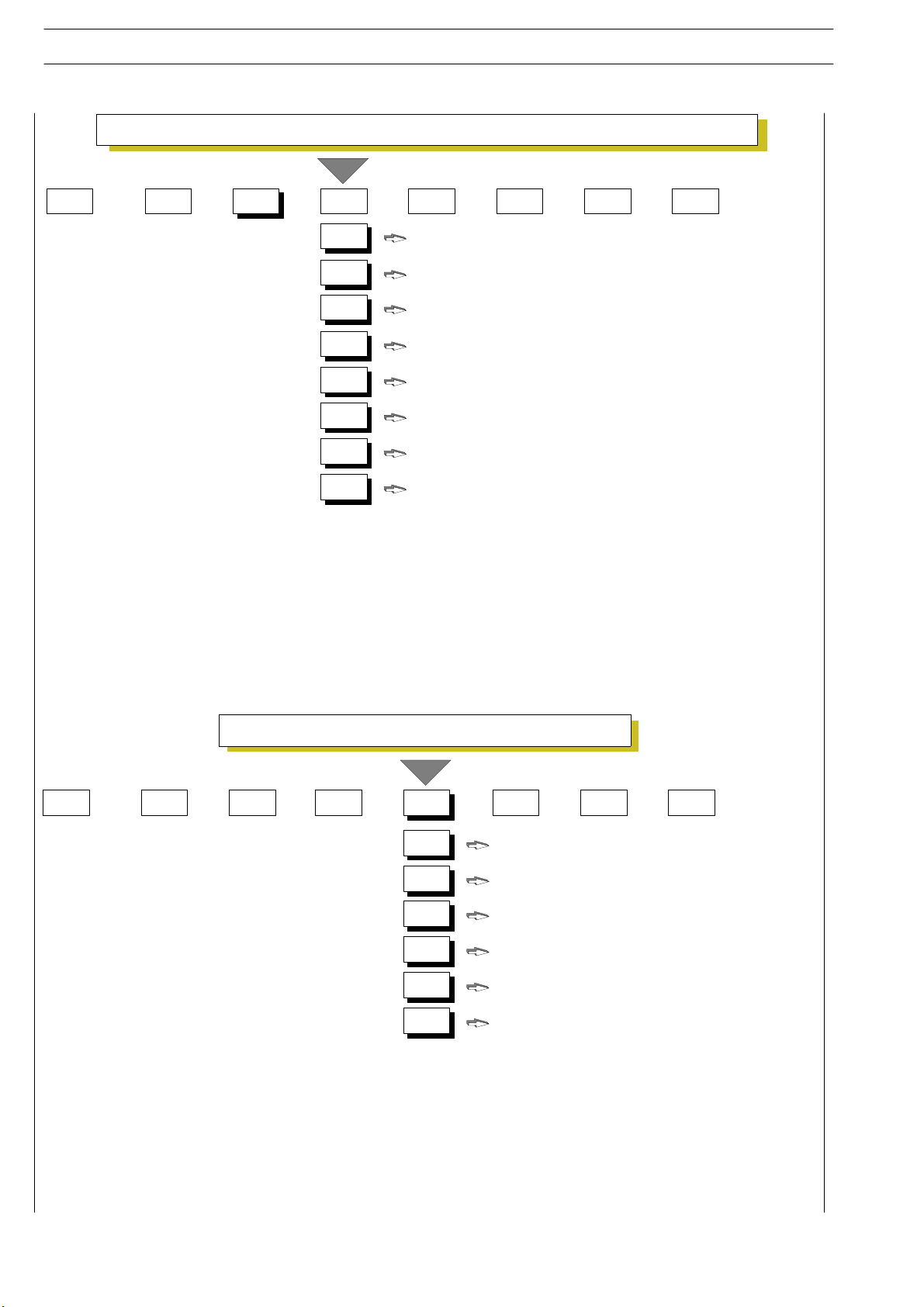
P.I.C. NUMBER CODING
CAB LIVEABILITY
AAB CDBCA
9STRALIS AT/AD GENERAL
M
M
N
= Stralis AD (Active Day)
= Stralis AT (Active Time)
TO TAL WEI GH T O N G RO UN D - AXL ES CONFIGURATION
AAB CDBC
A
C
D
E
F
G
H
K
=4x2;18-20ton.
=4x2T;19-20ton.
=6x2C;26ton.
=6x2P;26ton.
=6x2P;26ton.
=4x2T;19-20ton.
J
=6x2C;26ton.
=6x4;26ton.
ENGINE
ABCDBCA
L
M
N
=4x2P;19-20ton.
=6x2P;26ton.
=6x2P;26ton.
A
H
L
K
P
Q
R
E 270
E 400
E 430
E 310
E 300
E 352
Print 603.93.141 Base - January 2003
Page 19
10
GENERAL
SUSPENSION TYPE - REAR AXLE TYPE - TYPE OF ADDITIONAL AXLE
STRALIS AT/AD
ABCDBCA
A
A
B
C
E
E
F
G
H
* = Suspensions with 5886/D front axle
TWIN = Twin rear wheels
CENT = Middleaxle(6x2Cvehicles)
SING = Added axle with rear single wheels
STER = Added axle with rear steering single wheels
HR = Double reduction rear axle
SR = Simple reduction rear axle
Mechanical - SR - TWIN
Pneumatic - SR - CENT/SING/TWIN
-SR-CENT/SING
Pneumatic - HR (Tractor 4x2)
Pneumatic - HR - SR - STER (Chassis cab 6x2P)
-SR-STER
(*) - SR - SING
(*) - SR - STER
VERSION COMBINATION - USE
AA CDCA B
Cartran = Car transport
LOW T R = Lowered tractor
STD = Standard use
GRAV = Heavy duty use
B
1
2
H
M
N
T
= Chassis cab - STD
=Tractor-STD
=Tractor-GRAV
= Cartran - STD -Tractor
= Cartran - STD - Chassis cab
= LOW TR - STD
Base - January 2003 Print 603.93.141
Page 20
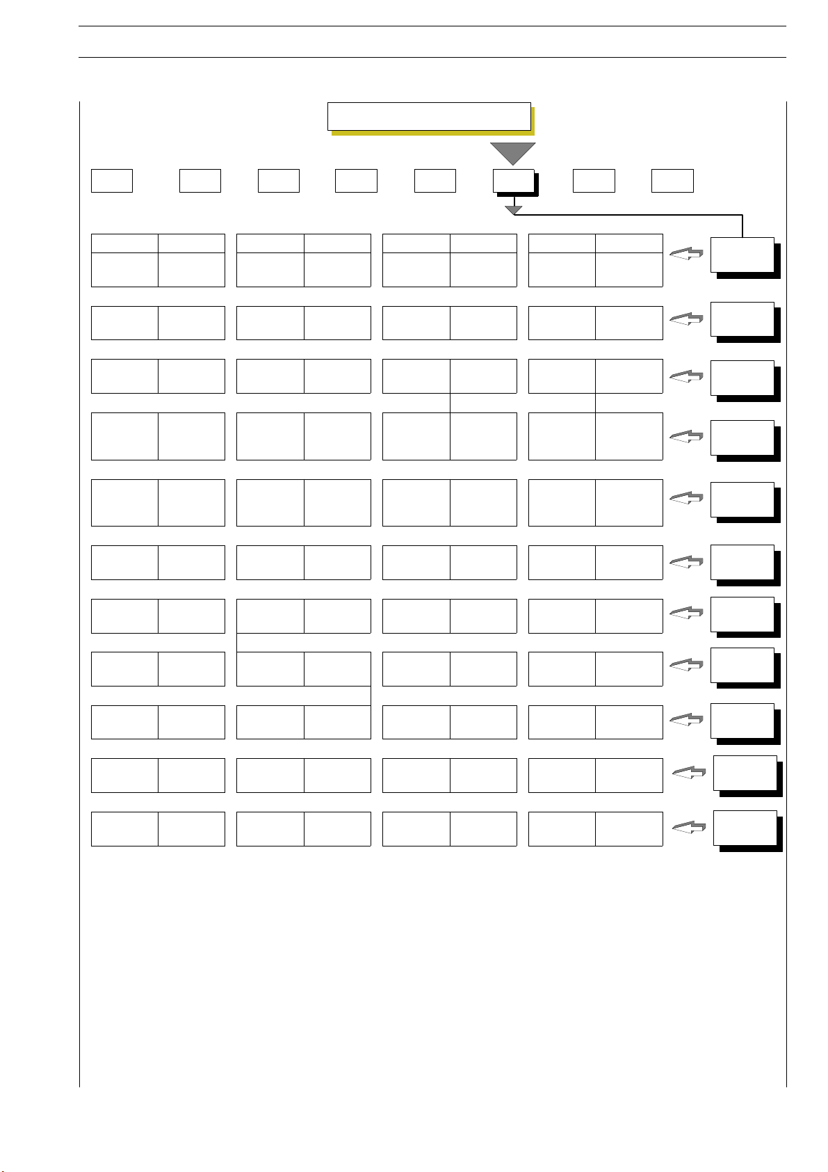
WHEELBASE
CAA CDBA B
VERSION WHEELBASE VERSION WHEELBASE VERSION WHEELBASE VERSION WHEELBASE
T6x2C 3800 T4x2 3650 6x2P 3120 T6x4 2800
11STRALIS AT/AD GENERAL
1
T6x4 3200
6x2P
C4x2
C4x2 6300 6x2P 6050
3805
T4x2
C6x2C
C4x2
C6x2C
6x2P
C4x2
C6x2
6x2P
C4x2
6x2P
C4x2
6x2P
C4x2
6x2P
3800
4200
4500
4800
5100
5700
2
3
4
5
6
7
8
9
C4x2 5500
C4x2 6300
Print 603.93.141 Base - January 2003
L
M
Page 21

12
Mechanical
L
L
LeftRight
GENERAL
GEARBOX - BRAKES COMBINATION
AA DBCA B C
STRALIS AT/AD
GEARBOX
Mechanical
A
ISON Disc Drum
EuroTronic 12 A S 2301 Disc Disc
EuroTronic 12 A S 2301 Disc Drum
NO YES
Disc Disc
Disc Drum
BRAKES
CAB - DRIVE - BRAKES COMBINATION
A
B
D
E
F
AABCA B C D
DRIVE
1
A
Base - January 2003 Print 603.93.141
Page 22
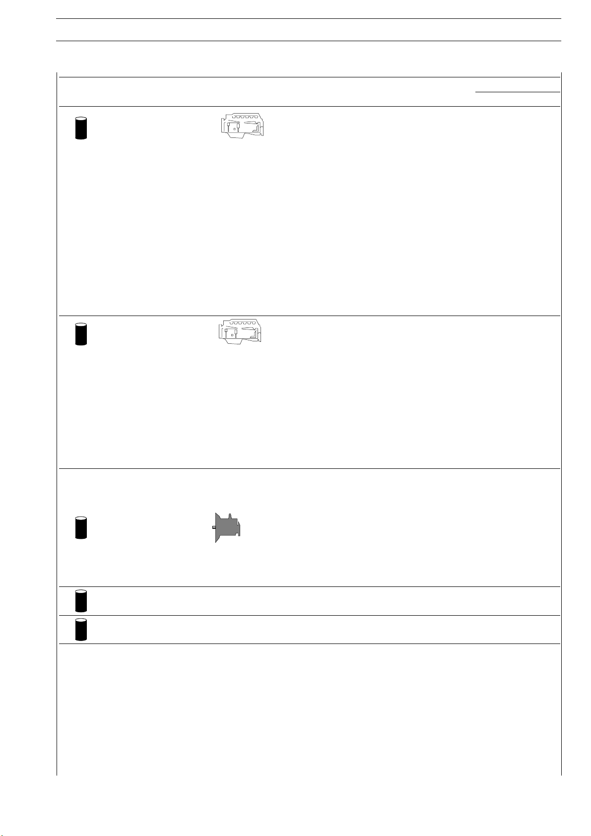
REPLENISHING FLUIDS
t
y
g
UraniaLD5
A
1
13STRALIS AT/AD GENERAL
LUBRICANTS RECOMMENDED BY IVECO
Urania FE 5W30
Urania LD5
Urania Turbo LD
Urania FE 5W30
Urania LD5
Urania Turbo LD
Tutela Truck FE-Gear
Tutela ZC 90
* Quantity 1stfilling
(1)
(1)
1
PARTS TO BE FILLED UP Quanti
Litres
Engine F2B
Total capacity for first filling
Capacity:
- engine sump min level
- engine sump max level
- quantity in circulation that
does not flow back to the engine sump
- quantity contained in the cartridge filter (which has to be
added to the cartridge filter refill)
Engine F3A
st
Total capacity 1
filling
Capacity:
- engine sump at minimum level
- engine sump at maximum level
- quantity in c irculation that does not return to sump
- quantity contained in cartridge filter (to
add when changing the cartridge filter)
Gearbox
ZF 9 S 109 *
ZF 16 S 151 *
ZF 16 S 151 + Intarder *
ZF 16 S 181 *
ZF 16 S 181 + Intarder*
ZF 16 S 221 *
ZF 16 S 221 + Intarder*
EuroTronic automated 12 AS 2301*
EuroTronic automated 12 AS 2301* + intarder
28 25,2
12.5
23
5
2.5
30 29.8
17
25
7
2.5
8
11
18.5
13
21.5
13
21.5
12
23
K
11,2
21
4.5
2.3
15.3
22.5
6.3
2.3
7.2
10
16.65
12
19.35
12
19.35
11
21
Tutela GI/
TutelaTruckFE-Gear
Tutela ZC 90
Allison MD 3060 P - MD 3066 P 18 16
Power take off (Multipower) 2.5
(1) IVECO recommends using these oils for reasons of fuel economy. IVECO provides new vehicles already with these types of
lubricants. Also suited for cold climates (minimum temperature down to -30ºC)
These quantities are not decisive. An exact check must be made by verifying the levels
Print 603.93.141 Base - January 2003
Page 23
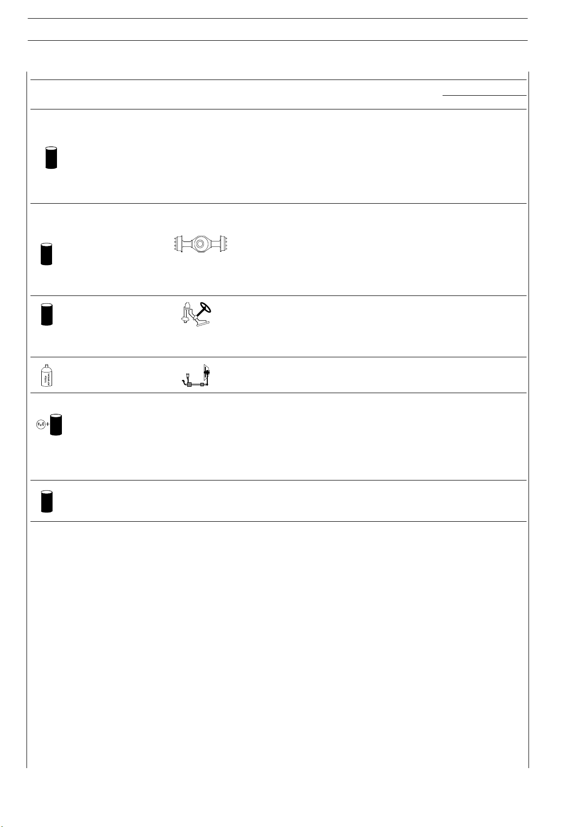
14
LUBRICANTSRECOMMENDEDBYIVEC
OPA
g
A
g
v
GENERAL
REPLENISHING FLUIDS
STRALIS AT/AD
Tutela Truck FE-Axle
Tutela W140/M-DA
Tutela W90/M-DA
Tutela Truck
FE-Axle
(2)
TutelaW140/M-D
Tutela W90/M-DA
Tutela GI/A
Tutela TRUCK
DOT SPECIAL
RTS FOR REPLENISHING
Front hubs (single)
FRONT AXLE 5876/4-/5 (F8021)
(2)
3
3
FRONT AXLE 5886/5
ADDED AXLE::
Steering central 5876/4 (F 8021)
Rigid rear 55080/D1 (N 8071)
Rigid rear 56082/D1 (N 9171)
Steering rear 57080/DI (N 8072)
Bridge Meritor MS 13-175/T - MS 13-175/D:
V (mechanical suspension)
V (pneumatic suspension)
Bridge 451391 HR
Rear axle Meritor in tandem RT 160E/1
- middle
-rear
Power steering
*Excludin
ehicleswith steeringrear axle
** For vehicles with steering rear axle only
Clutch circuit
(excluding vehicles with Euro Tronic gearbox)
Litres k
0.35
0.35
0.35
0.35
0.35
0.35
18.5
17
16
18.5
16.5
0.32
0.32
0.32
0.32
0.32
0.32
16.5
15.5
14.5
16.6
14.8
2.7*
13.5**
0.5 0.45
2.4
12
Quantity
Cooling system
µ23.4
µ27
µ39.6
µ57.6
Water+Paraflu
11
Engine F2B Total capacity*
Engine F2B with Intarder Total capacity*
Engine F3A Total capacity*
Engine F3A with Intarder Total capacity*
µ34
µ50
µ38
µ58
*=Protective anti -freeze
(concentration 50% freezing point —35°C)
Tutela LHM
Cab tilting system 0.6 0.54
(2) Only on axles with disc brakes, IVECO recommends using these oils for reasons of fuel economy. IVECO provides new vehicles
already with these types of lubricants. Also suited for cold climates (minimum temperature down to -30ºC)
(3) Specific for cold climates
These quantities are not decisive. An exact check must be made by verifying the levels
Base - January 2003 Print 603.93.141
Page 24

International lubricant designation FL products
Engine oil
Meets the specifications:
ACEA E4 with a totally synthetic base SAE 50W 30
ACEA E5 with a mineral base SAE 15W 40
ACEA E3 with a mineral base SAE 15W 40
URANIA FE 5W30
Urania LD5
Urania Turbo LD
Oil for differential gear and wheel hubs
Meets the specifications:
API GL5, MT-1 with a totally synthetic base SAE 75W 90
API GL5 with a mineral base SAE 85W 140
API GL5 with a mineral base SAE 80W 90
Tutela Truck FE-Axle
Tutela W140/M-DA
Tutela W90/M-DA
Oil for mechanical gearboxes
Containing non-EP anti-wear additives
Meets the specifications:
API GL4 with a totally synthetic base SAE 75W 85
API GL3 with a mineral base SAE 80W 90
Tutela Truck FE-Gear
Tutela ZC90
Oil for power steering and hydrostatic transmissions
A.T.F. DEXRON II D
Grease for general greasing
based on lithium soaps, N.L.G.I. consistency no. 2
Specific grease for bearings and wheel hubs
based on lithium soaps, N.L.G.I. consistency no. 3
Tutela GI/A
Tutela MR 2
Tutela MR 3
Clutch drive fluid
Conforming to N.H.T.S.A. standards 116, ISO 4925, Std. SAEJ 1703,
Tutela TRUCK DOT SPECIAL
IVECO STANDARD 18-1820
Mineral oil for hydraulic circuits
In compliance with IVECO STANDARD 18-1823
Windscreen washer fluid, mixture of spirit, water and surfactants
CUNA NC 956-11
Tutela LHM
Tutela PROFESSIONAL SC 35
Grease for central lubrication systems based on lithium soaps,
with synthetic base, N.L.G.I. no. 2.
Tutela COMAR 2
Working temperatures: from —30°C to +140°C
Concentrated protective fluid for radiators
based on ethylene glycol containing corrosion inhibitors, conforming to the
Paraflu
11
standard: IVECO-STANDARD 18-1830
15STRALIS AT/AD GENERAL
Print 603.93.141 Base - January 2003
Page 25

16
Print603.43.671
GENERAL
STRALIS AT/AD
Base - January 2003 Print 603.93.141
Page 26

STRALIS AT/AD
ENGINE 1
SECTION 2
Engine
Page
- F2B Engine 3............................
- F3A Engine 113...........................
- Hidrocar pressure take-off on timing system
(P.T.O. - Optional) 223.....................
Print 603.93.141 Base - January 2003
Page 27

2
ENGINE
TRALIS AT/AD
S
Base - January 2003 Print 603.93.141
Page 28

STRALIS AT/AD
ENGINE F2B 3
Print603.43.671
F2B Engine
Page
VIEWS OF THE ENGINE 8..................
GENERAL CHARACTERISTICS 13.............
ASSEMBLY CLEARANCE DATA 16............
TIGHTENING TORQUES 22.................
TOOLS 28................................
DISMANTLING THE ENGINE ON THE BENCH 40
REPAIR OPERATIONS 47....................
CYLINDER BLOCK 47.......................
- Checks and measurements 47...............
CYLINDER LINERS 48.......................
- Fitting and checking protrusion 49............
- Removal 49.............................
- Replacing cylinder liners 49..................
CRANKSHAFT 50..........................
- Measuring main journals and crank pins 51......
PRELIMINARY MEASUREMENT OF MAIN AND BIG
END BEARING SHELL SELECTION DATA 52..
- Replacing the timing control gear and
the oi l pump 59..........................
- Checking main journal installation clearance 59...
- Checking crankshaft end float 60.............
PISTON-CONNECTING ROD ASSEMBLY 61....
- Removal 61.............................
- Measuring the diameter of the pistons 62.......
- Conditions for correct gudgeon pin-piston
coupling 62..............................
- Piston rings 63...........................
CONNECTING ROD 64.....................
- Checking connecting rod alignment 65.........
Print 603.93.141 Base - January 2003
Page 29

4
ENGINE F2B
TRALIS AT/AD
S
- Mounting the connecting rod-piston assembly 65.
- Mounting the piston rings 65.................
- Fitting the connecting rod-piston assembly into
the piston liners 66........................
- Piston protrusion check 66..................
- Checking assembly clearance of big end pins 67..
CYLINDER HEAD 67........................
- Valve removal 67..........................
- Checking the planarity of the head on
the cylinder block 67.......................
VALVE 67.................................
- Removing deposits and checking the valves 67...
VALVE GUIDES 68..........................
- Replacing of valve guides 69.................
Page
Page
- Fitting the connecting rod-piston assembly into
the cylinder liners 80.......................
ENGINE FLYWHEEL 83......................
- Fitting engine flywheel 83...................
- Fitting camshaft 84.........................
- Fitting pump-injectors 85....................
- Fitting rocker-arm shaft assembly 85...........
- Camshaft timing 86........................
- Phonic wheel timing 88.....................
- Intake and exhaust rocker play adjustment and
pre-loading of rockers controlling pump injectors. 89
ENGINE COMPLETION 90..................
LUBRICATION 93..........................
- Replacing - Reaming the valve seats 69.........
REPLACING INJECTOR HOLDER CASES 69.....
- Removal 69..............................
- Checking protrusion of injectors 71............
TIMING GEAR 72...........................
- Checking cam lift and pin alignment 72.........
- Camshaft 73.............................
- Bushes 73...............................
- Replacing camshaft bushes using
beater 99360487 74.......................
- Removal 74..............................
- Assembly 74.............................
VALVE SPRINGS 75.........................
- Fitting the valves and oil seal ring 75...........
- Oil pump 95.............................
- Overpressure valve 95.....................
- Oil pressure control valve 96................
- Heat exchanger 96........................
- By-pass valve 97..........................
- Thermostatic valve 97......................
- Engine oil filters 97........................
COOLING 99..............................
- Description 99............................
- Operation 99............................
- Water pump 101..........................
- Thermostat 101...........................
- Electromagnetic coupling 101.................
ROCKER SHAFT 76.........................
- Rocker 76...............................
- Shaft 76.................................
TURBOCHARGER 102.......................
TURBOCHARGING 102......................
TURBO COMPRESSOR HOLSET HX 40V 104.....
ASSEMBLING THE ENGINE ON THE BENCH 77.
- Actuator 107..............................
DIAGRAM SHOWING THE UNDERBLOCK FIXING
SCREWS TIGHTENING ORDER 79..........
Base - January 2003 Print 603.93.141
- Solenoid valve for VGT control 107............
Page 30

STRALIS AT/AD
FUEL FEED 108.............................
- Replacing injectors-pump 109.................
- Injector-pump 109..........................
- Fuel pump 109............................
- Injector Phases 110.........................
ENGINE F2B 5
Page
Print 603.93.141 Base - January 2003
Page 31

6
ENGINE F2B
TRALIS AT/AD
S
Base - January 2003 Print 603.93.141
Page 32
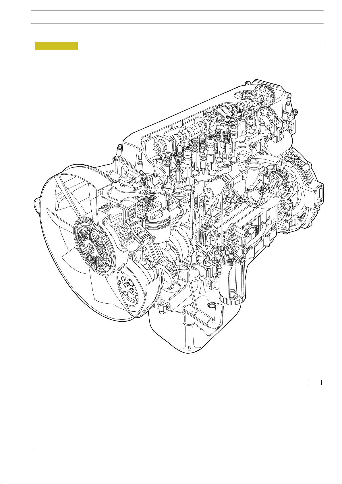
STRALIS AT/AD
Figure 1
ENGINE F2B
7
78840
F2B ENGINE
Print 603.93.141 Base - January 2003
Page 33
8
ENGINE F2B
VIEWSOFTHEENGINE
ENGINE
S
TRALIS AT/AD
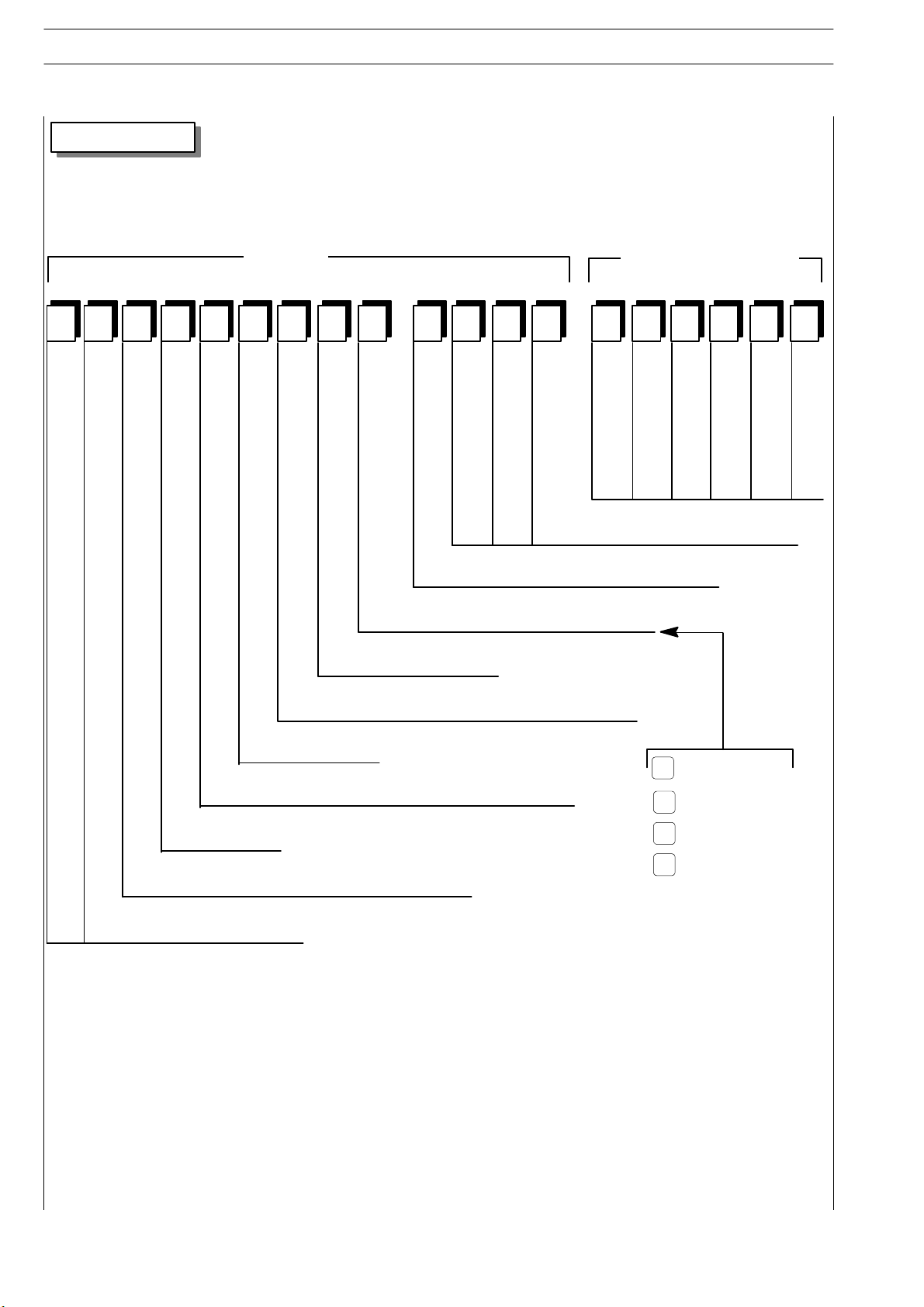
TYPE PART NUMBER
F 2 B E 0 6 8 1 A
Engine power output or torque level
Use (eg I = truck)
Fuel feed + injection (TCA, direct injection diesel engine)
Number of cylinders
Number of strokes and cylinders’ position (eg 0 = 4 strokes,
vertical)
Engine
A 0 0 1
*
Only for exh aust gas level with
thesametorqueandpowercurves
-
Version number within the B.o.M.
Progressive production number
A
352 CV 131 kgm
310 CV 114 kgm
B
E
301 CV 113 kgm
F
273 CV 114 kgm
Engine family evolution (also irrespective of the
displacement)
Indicates the engine family
Base - January 2003 Print 603.93.141
Page 34
STRALIS AT/AD
Figure 2
ENGINE F2B
9
rpm
52244
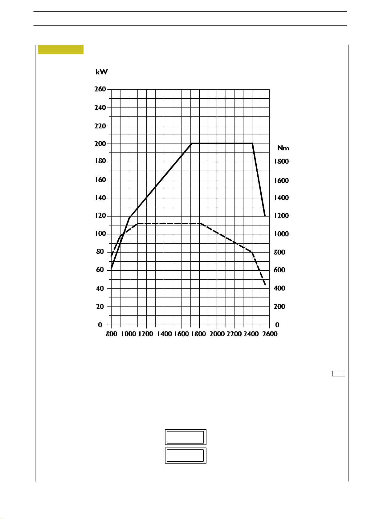
F2BE0681F: POWER-TORQUE CURVES
Max OUTPUT 200 kW at 2400 rpm
Max TORQUE 1115 Nm at 1000 to 1770 rpm
Print 603.93.141 Base - January 2003
273HP
114 kgm
Page 35
10
ENGINE F2B
Figure 3
S
TRALIS AT/AD
rpm
52243
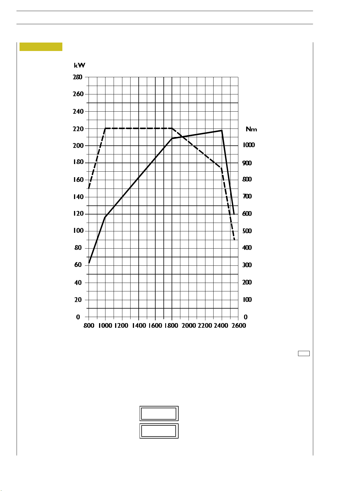
F2BE0681E: POWE R-TORQUE CURVES
Max OUTPUT 221 kW at 2400 rpm
Max TORQUE 1110 Nm at 1000 rpm
Base - January 2003 Print 603.93.141
301HP
113 kgm
Page 36
STRALIS AT/AD
Figure 4
ENGINE F2B
11
rpm
47531
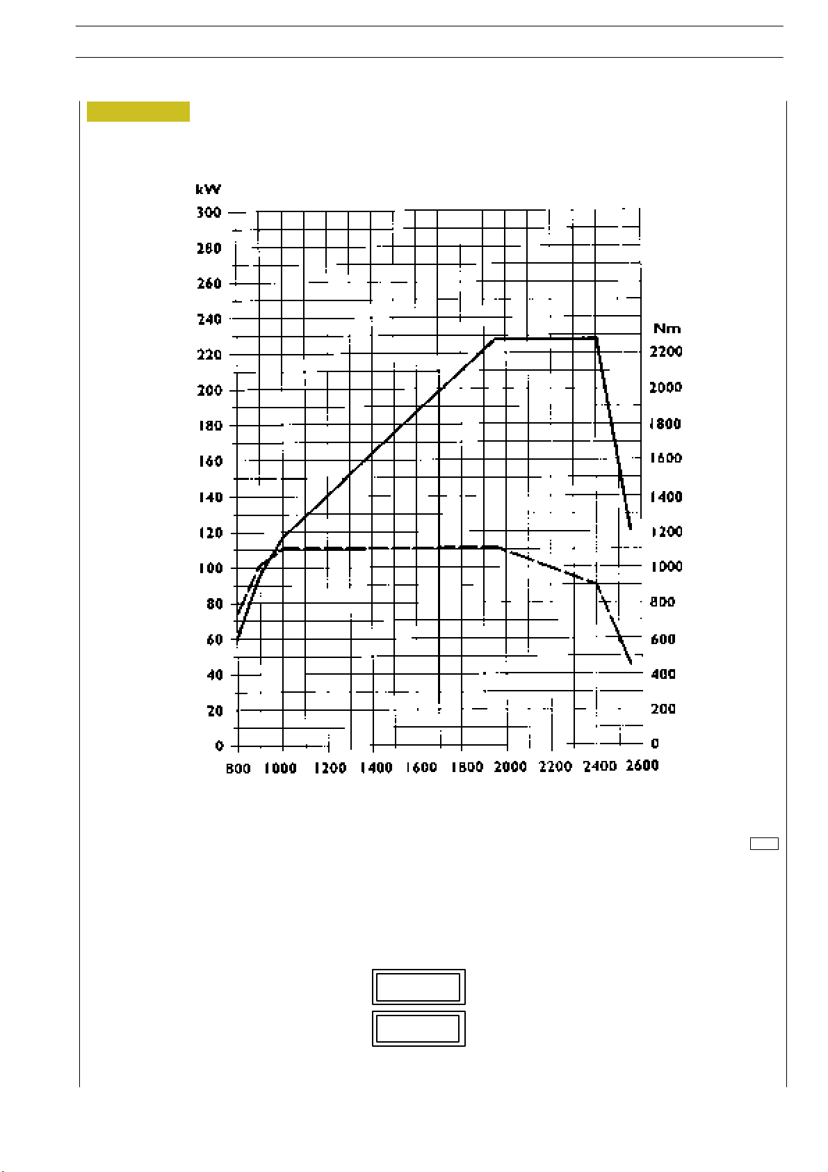
F2BE0681B: POWER-TORQUE CURVES
Max OUTPUT 228 kW at 2400 rpm
Max TORQUE 1100 Nm at 1000 to 1950 rpm
Print 603.93.141 Base - January 2003
310HP
114 kgm
Page 37
12
ENGINE F2B
Figure 5
S
TRALIS AT/AD
rpm
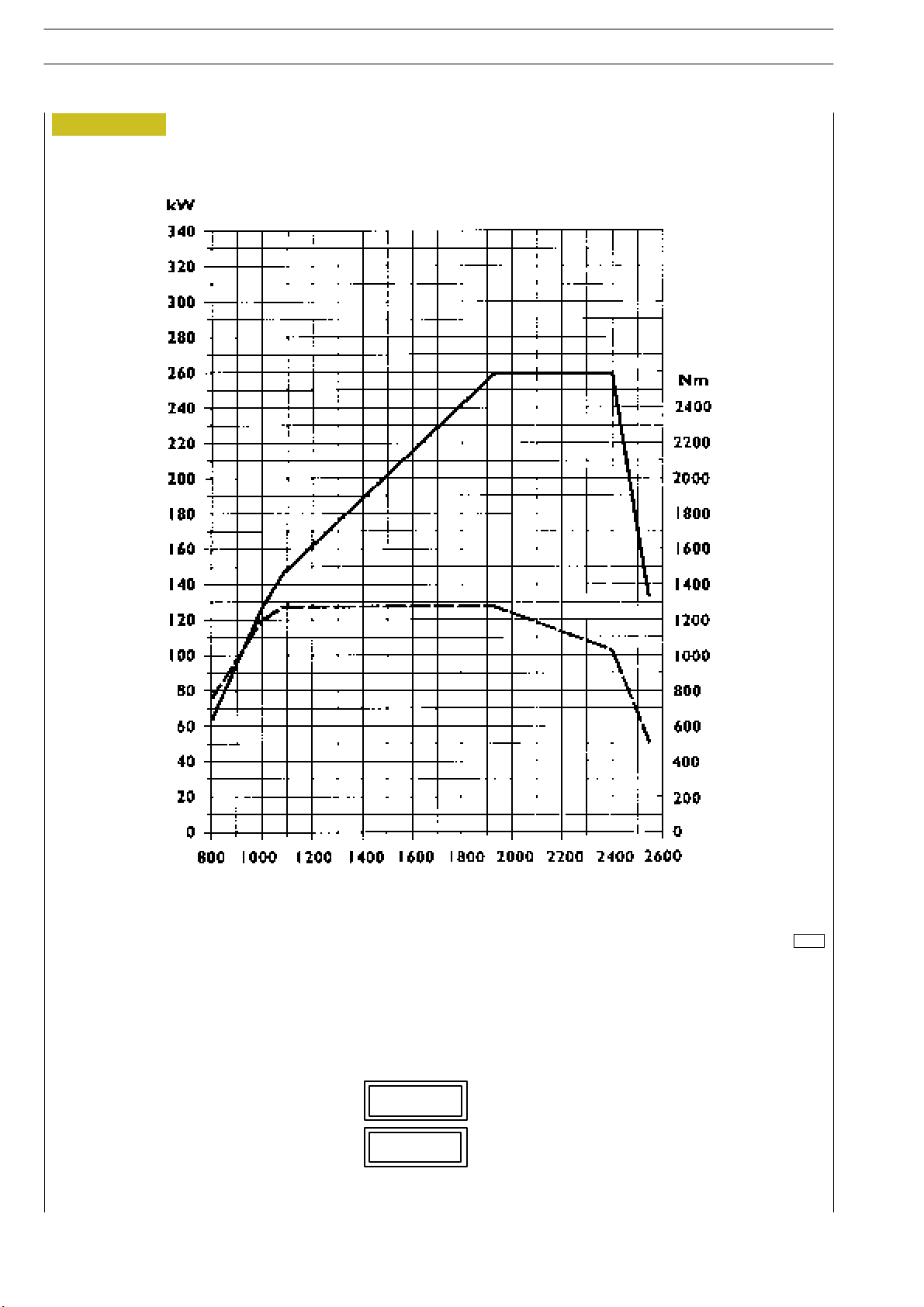
47532
F2BE0681A: POWER-TORQUE CURVES
Max OUTPUT 259 kW at 2400 rpm
Max TORQUE 1280 Nm at 1080 to 1930 rpm
Base - January 2003 Print 603.93.141
352HP
131 kgm
Page 38
STRALIS AT/AD
r
r
gedwit
r
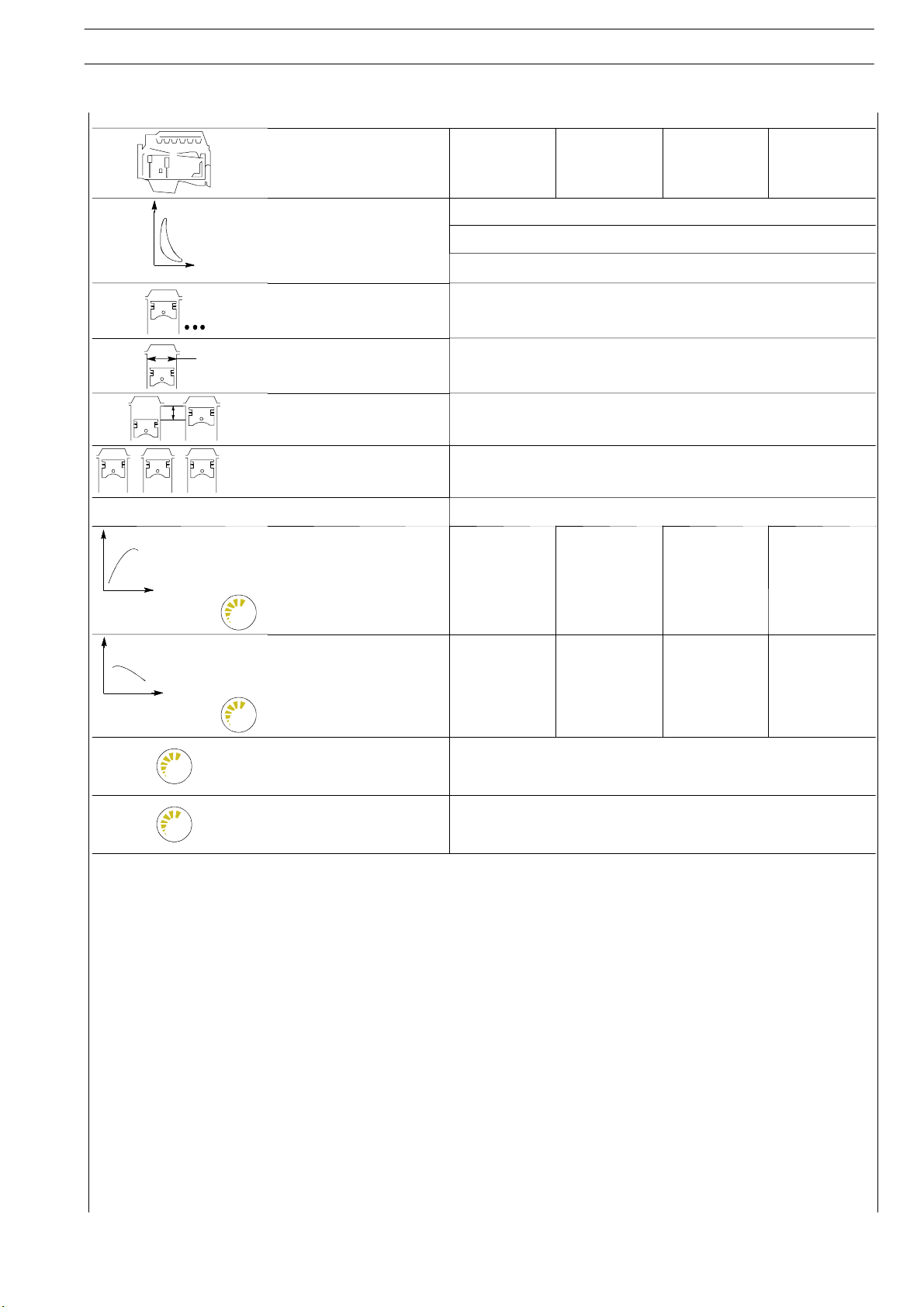
GENERAL CHARACTERISTICS
ENGINE F2B
13
Type
Cycle Diesel 4 strokes
Feeding
Injection Direct
N. of cylinders 6 o n-line
∅
Diameter mm 115
Stroke mm 125
+++..=
ρ
Total displacement cm
Compression ratio 16 ± 0.8
Max. power KW
F2BE0681A F2BE0681B F2BE0681E F2BE0681F
Tu
bocha
3
259
(HP)
rpm 2400 2400 2400 2400
(352)
228
(310)
7790
haftercoole
221
(301)
200
(273)
Max. torque Nm
(Kgm)
rpm
Engine idling speed,
no load
rpm
Maximum engine
speed, no load
rpm
1280
(131)
1080 to 1930 1000 to 1950 1000 1000 to 1770
1115
(114)
1110 (113)
525 ± 25
2760 ± 20
1115
(114)
Print 603.93.141 Base - January 2003
Page 39

14
N
type_
ENGINE F2B
S
TRALIS AT/AD
Type
F2B
A
VALVE TIMING
opens before T.D.C. A
B
closes after B.D.C. B
17°
31°
C
opens before B.D.C. D
closes after T.D.C. C
48°
9°
D
For t iming check
mm
_
X
X
mm
_
Running
ba
mm
0.35 to 0.45
X
0.35 to 0.45
FEED
Injection
type Bosch
mm
Through fuel pump - Filters
With electronically regulated injectors PDE 30
pump injectors controlled by overhead camshaft
ozzle
Injection order 1-4-2-6-3-5
Injection pressure bar
1500
r
Injector calibration bar
Base - January 2003 Print 603.93.141
Page 40
STRALIS AT/AD
Holset,wit
hvar
iab
leg
try
1.5
5
2
8
F
iat
lubri
(accordingtoE39
6
2.5
ENGINE F2B
15
COOLING
Urania Turbo LD
(according to E3-96
(according to E2-96
bar
cants
standard)
Urania Turbo
standard)
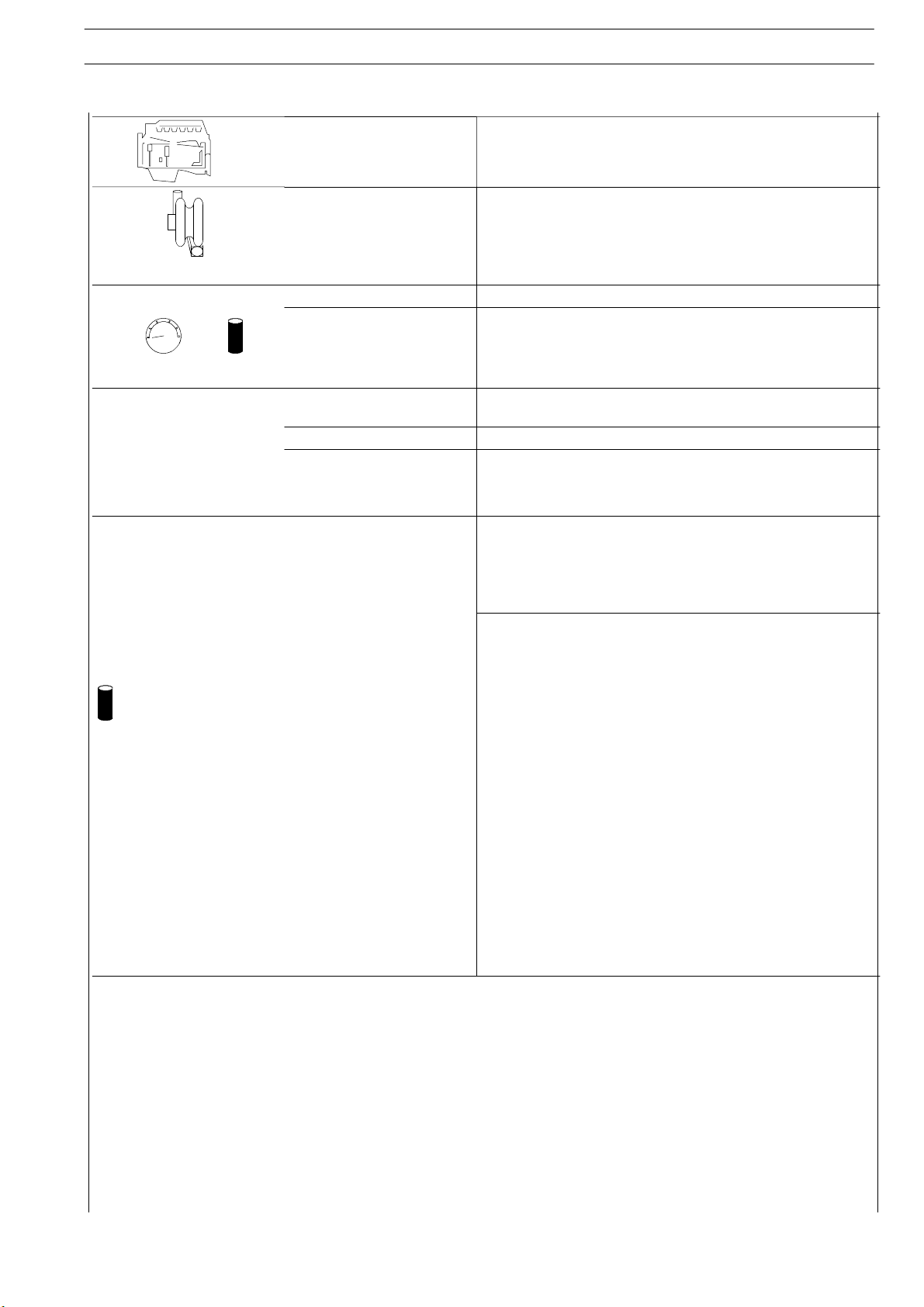
Type
F2B
SUPERCHARGING
eome
Turbocharger
type: HY 40 V
LUBRICATION Forced by gear pump, pressure control valve, o il filter
Oil pressure, engine hot
o
(100
C ± 5oC):
at idling speed bar
1.5
5
at maximum speed bar
By cent rifugal pump, regulating thermostat, viscostatic fan,
radiator and heat exchanger
Water pump control By belt
Thermostat: N. 1
starts to open:
fully open:
~85 ºC
_
OIL FILLING
Total capacity at 1st filling
liters
kg
28
25.5
Capacity:
- engine sump min level
liters
kg
- engine sump max level
liters
12.5
11.2
kg
- quantity in circulation that
does not flow back to the
23
21
engine sump
liters
kg
5
- quantity contained in the
cartridge filter (which has to
be added to the cartridge filter
refill)
liters
kg
2.3
Print 603.93.141 Base - January 2003
Page 41
16
∅
1
X
X
ENGINE F2B
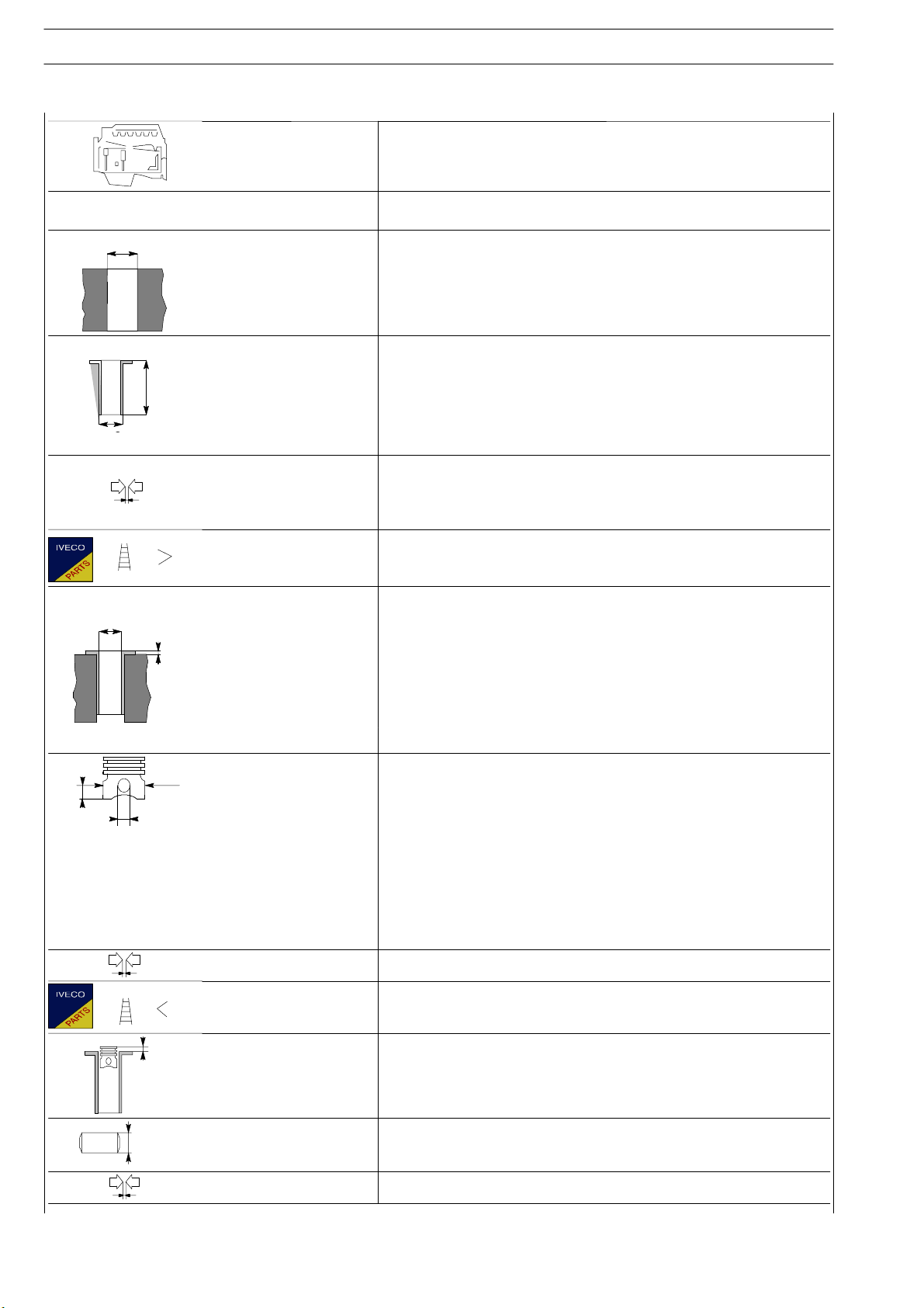
ASSEMBLY CLEARANCE DATA
Type F2B
S
TRALIS AT/AD
CYLINDER BLOCK AND CRANK
MECHANISM COMPONENTS
∅
1
Cylinder sleeve bore
upper
∅ 1
lower
Cylinder liners:
outer diameter:
L
upper
∅ 2
lower
∅2
length L
Cylinder sleeve -
crankcase bore
upper
lower
Outside diameter ∅ 2
Cylinder sleeve
∅
3
mm
130.200 to 130.225
128.510 to 128.535
130.161 to 130.186
128.475 to 128.500
0.014 to 0.064
0.010 to 0.060
A* 115.000 to 115.012
inside diameter ∅ 3
X
B* 115.010 t o 115.022
Protrusion X 0.035 to 0.065
* Available dia. class
Pistons:
measuring dimension X
outside diameter ∅ 1A• 114.888 to 114.900
∅
2
outside diameter ∅ 1B•• 114.898 to 114.910
outside diameter ∅ 2
• ClassApistonssuppliedasspares.
•• ClassBpistonsarefittedinproductiononlyand
are not supplied as spares.
Piston - cylinder sleeve 0.100 to 0.124
Piston diameter ∅ 1 _
X
Pistons protrusion X 0.32 to 0.99
18
46.010 to 46.018
114.898 to 114.910
∅
3
Gudgeon pin ∅ 3 45.994 to 46.000
Gudgeon pin - pin housing 0.010 to 0.024
Base - January 2003 Print 603.93.141
Page 42
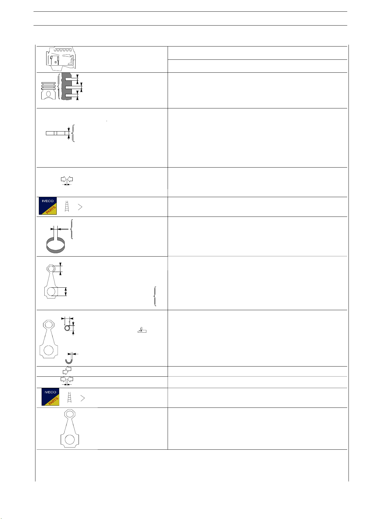
STRALIS AT/AD
F2BTy
p
X
12X
X32
X
3
X
p
raper
ring
pringS3
3.975
to3.990
X
2
X
3
X
∅
1
∅
ENGINE F2B
17
e
mm
X1* 2.71 to 2.74
Piston ring groov es X 2 2.55 to 2.57
X3 4.02 to 4.04
*measured on ∅ of 112 mm
Piston rin gs:
trapezoidal seal S 1*
1
lune seal S2
2.575 to 2.595
2.470 to 2.490
2SS
S
with slits and internal
milled sc
3
s
*measured on ∅ of 112 mm
1 0.115 to 0.165
Piston rings -
grooves 2
0.060 to 0.100
3 0.030 to 0.065
∅4
1
∅ 2
Piston rings _
1
X
2
Piston ring end gap in
cylinder liners:
X1 0.35 to 0.50
X2 0.70 to 0.96
X3 0.30 to 0.60
Small end bush housing
Ø1
49.975 to 50.000
Big end bearing
housing Ø2
Selection classes Ø2 2
Rated value 77.000 to 77.030
1
77.000 to 77.010
77.010 to 77.020
3
77.020 to 77.030
Small end bush diameter
outside ∅4 50.055 to 50.080
∅
3
inside ∅ 3
46.015 to 46.030
Bigendbearingshell S
S
Red
Green
Yellow
2.000 to 2.010
2.011 to 2.020
2.021 to 2.030
Small end bush - housing 0.055 to 0.105
Piston pin - bush 0.015 to 0.036
Big en d bearing shells 0.127 - 0.254 - 0.508
Connecting rod weight
A
g. 2890 to 2920
Class B g. 2921 to 2950
C g. 2951 to 2980
Print 603.93.141 Base - January 2003
Page 43
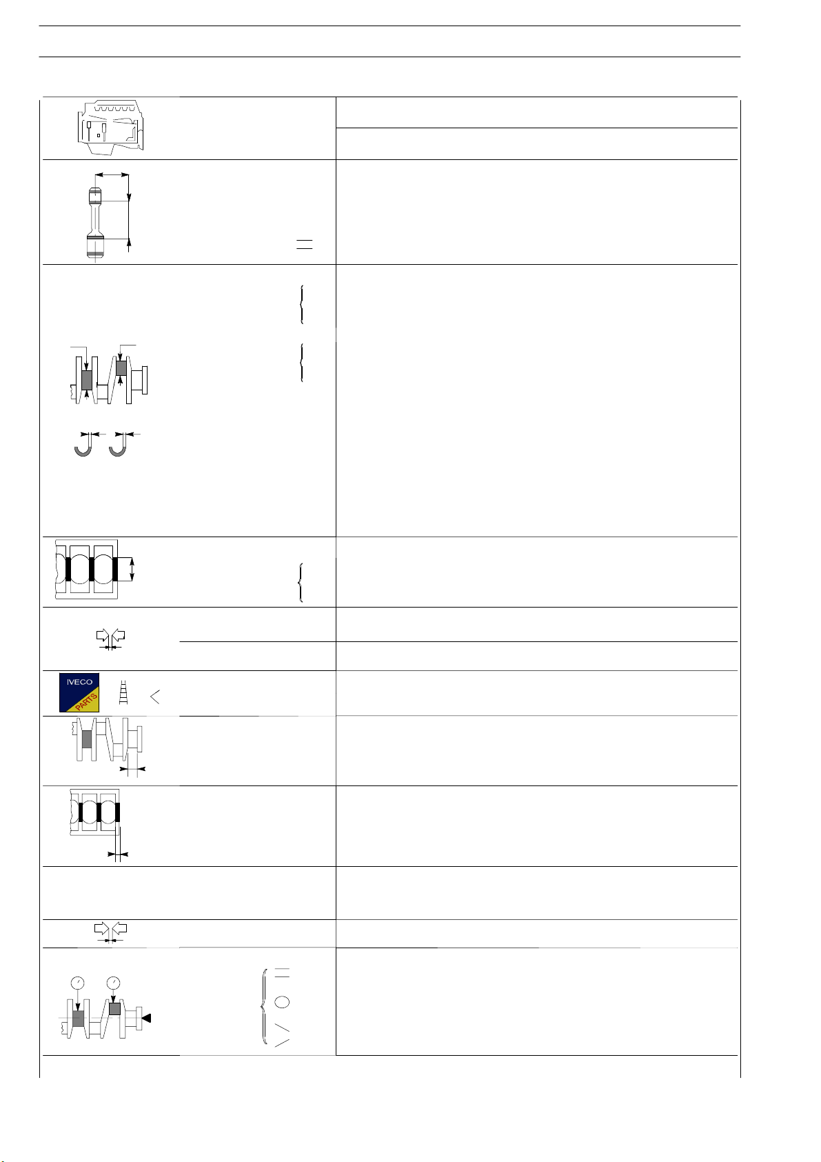
18
Typ
∅
∅
1
2
∅
∅
ENGINE F2B
S
TRALIS AT/AD
F2B
e
mm
X
12
S1S
2
3∅
Measuring dimension X 125
Max. connecting rod
axis misalignment
tolerance
0.08
Main journals ∅ 1 Rated value 82.910 to 82.940
1
Selection class 2
3
82.910 to 82.919
82.920 to 82.929
82.930 to 82.940
Crankpins ∅ 2 Rated value 72.915 to 72.945
1
Selection class 2
3
72.915 to 72.924
72.925 to 72.934
72.935 to 72.945
Main bearing
shells S1
Red
Green
Yellow D
3.000 to 3.010
3.011 to 3.020
3.021 to 3.030
Big end bearing
shells S2
Red
Green
Yellow D
2.000 to 2.010
2.011 to 2.020
2.021 to 2.030
Main bearing housings ∅ 3 Rated value 89.000 to 89.030
1
Selection class 2
3
Bearing shells main journals
Bearing shells big ends
89.000 to 89.009
89.010 to 89.019
89.020 to 89.030
0.040 to 0.080
0.035 to 0.075
Main bearing shells 0.127 - 0.254 - 0.508
Big end bearing shells 0.127 - 0.254 - 0.508
Main journal,
thrust bearing X1
39.96 to 40.00
X1
Main bearing housing,
thrust bearing X2
32.94 to 32.99
X2
X3
Thrust washer
halves X3
3.38 to 3.43
Driving shaft shoulder 0.11 to 0.30
12
1
≤ 0.05
Alignment
2
Ovality 1 - 2
Taper 1 - 2
_
0.010
0.010
D Fitted in production only and not supplied as spares
Base - January 2003 Print 603.93.141
Page 44
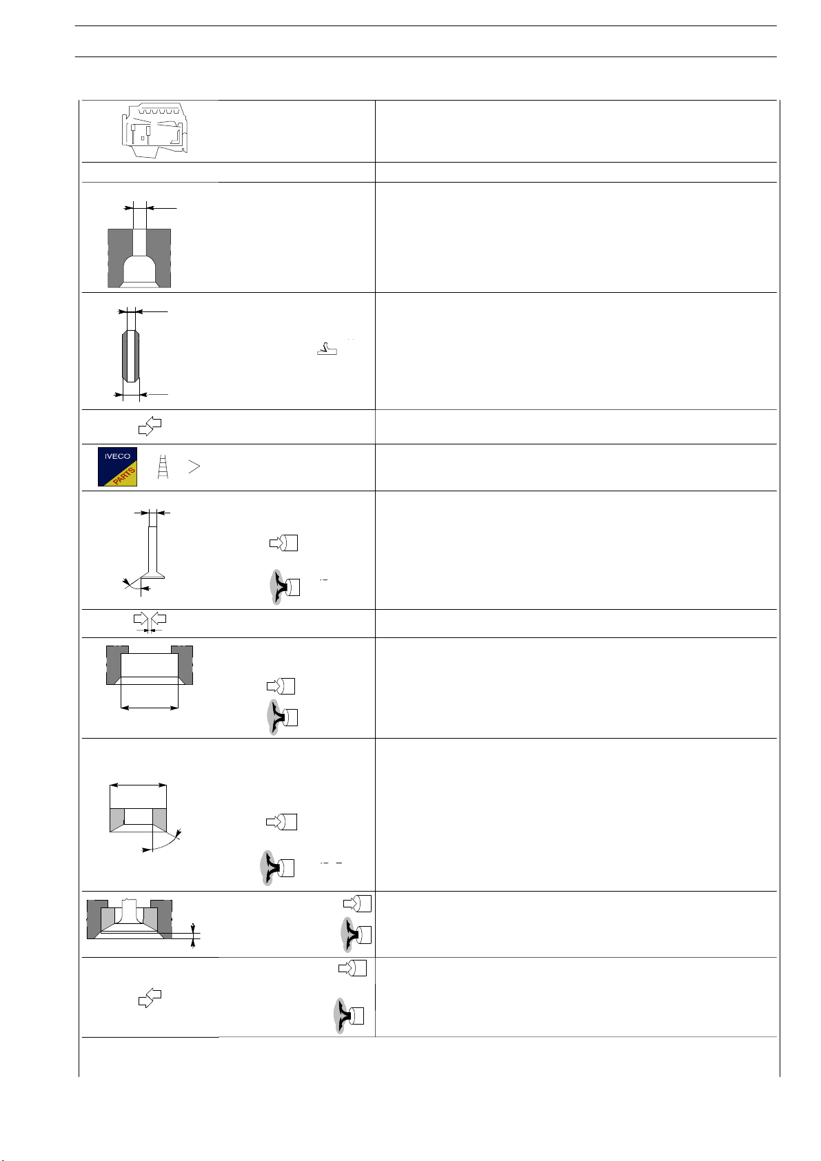
STRALIS AT/AD
∅
2
∅
4Valves
:
∅
4
∅
4
t
sea
t
Outsidediameterofvalv
e
∅
2
valve
X
Bet
w
11
Type F2B
CYLINDER HEADS - VALVE TRAIN mm
∅
1
Valve guide housings
in cylinder head
∅1
12.980 to 12.997
2∅
ENGINE F2B
19
∅
α
∅ 4
∅ 1
2
∅ 3
∅ 2
8.023 to 8.038
Valve guide
∅ 3
Valve guides - housings
in the cylinder heads
13.012 to 13.025
0.015 to 0.045
Valve guide _
Valves:
7.985 to 8.000
α
∅ 4
α
60° 30′±7′ 30″
7.985 to 8.000
45° +15′
Valve stem and its guide 0.023 to 0.053
Housing in head for valve
sea
∅1
∅1
41.985 to 42.020
40.985 to 41.020
Outside diameterofvalve
seat; angle of valve seat in
cylinder head:
∅ 2
α
α
∅ 2
α
Recessing of
42.060 to 42.075
60° - 30’
41.060 to 41.075
45° -30′
0.5 to 0.8
valve X
X
1.6 to 1.9
een valve
seat and head
Print 603.93.141 Base - January 2003
0.040 to 0.090
Page 45
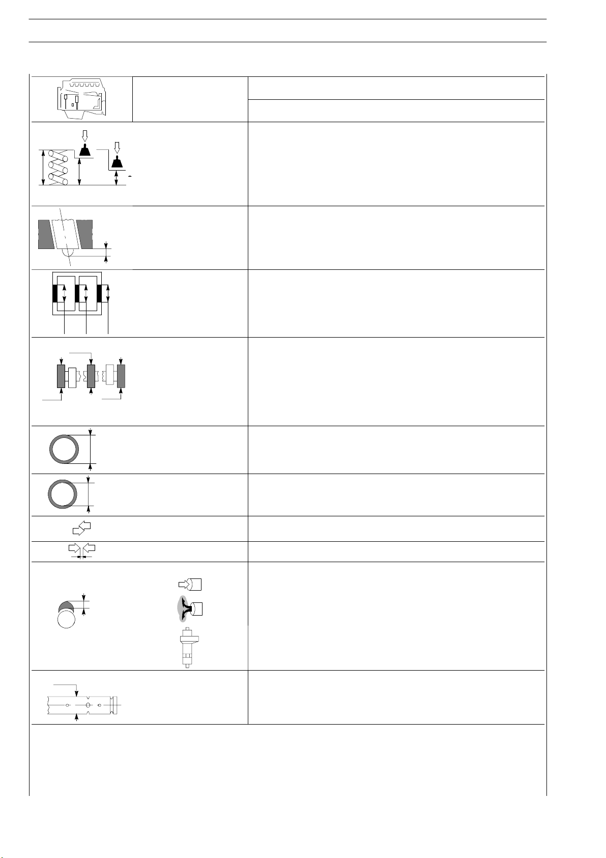
20
H
1H2
ENGINE F2B
S
TRALIS AT/AD
Type
F2B
mm
Valve outside spring
height:
free height H 62.6
H
H1
under a load of:
N 454 ± 22 H1 48.5
N 840 ± 42 H2 36.5
Injector protrusion X 0.7
X
Camshaft bush housing
fitted in the cylinder head:
∅
∅
∅
∅
1 ⇒ 7Ø
2
80.000 to 80.030
Camshaft journal diameter:
1 ⇒ 7Ø
75.924 to 75.940
∅
∅
1
∅
∅
∅
3
Camshaft bushing outer
diameter: ∅
Camshaft bushing
inner diameter: ∅
Bushings and housings in
engine block
80.090 to 80.115
75.990 to 76.045
0.060 to 0.115
Bushings and journals 0.050 to 0.121
Cam lift:
8.07
H
7.63
8.80 to 8.82
1
Rocker shaft ∅ 1
37.984 to 38.000
Base - January 2003 Print 603.93.141
Page 46
STRALIS AT/AD
ENGINE F2B
21
∅
∅
Type
Bushing housing in rocker
arms
Bushing outer diameter
forrockerarms:
Bushing inner diameter
forrockerarms:
F2B
mm
41.000 to 41.016
53.000 to 53.019
42.000 to 42.016
41.097 to 41.135
53.105 to 53.156
42.066 to 42.091
38.025 to 38.041
∅
50.025 to 50.041
38.015 to 38.071
Between bushings and
housings
0.081 to 0.135
0.086 to 0.156
0.050 to 0.091
Between rocker arms and
shaft
0.025 to 0.057
0.225 to 0.057
0.015 to 0.087
TURBOCHARGER
Type
End float
Radial play
Print 603.93.141 Base - January 2003
HOLSET, variable geometry
_
_
Page 47

22
ENGINE F2B
S
TRALIS AT/AD
TIGHTENING TORQUES
PART TORQUE
Nm kgm
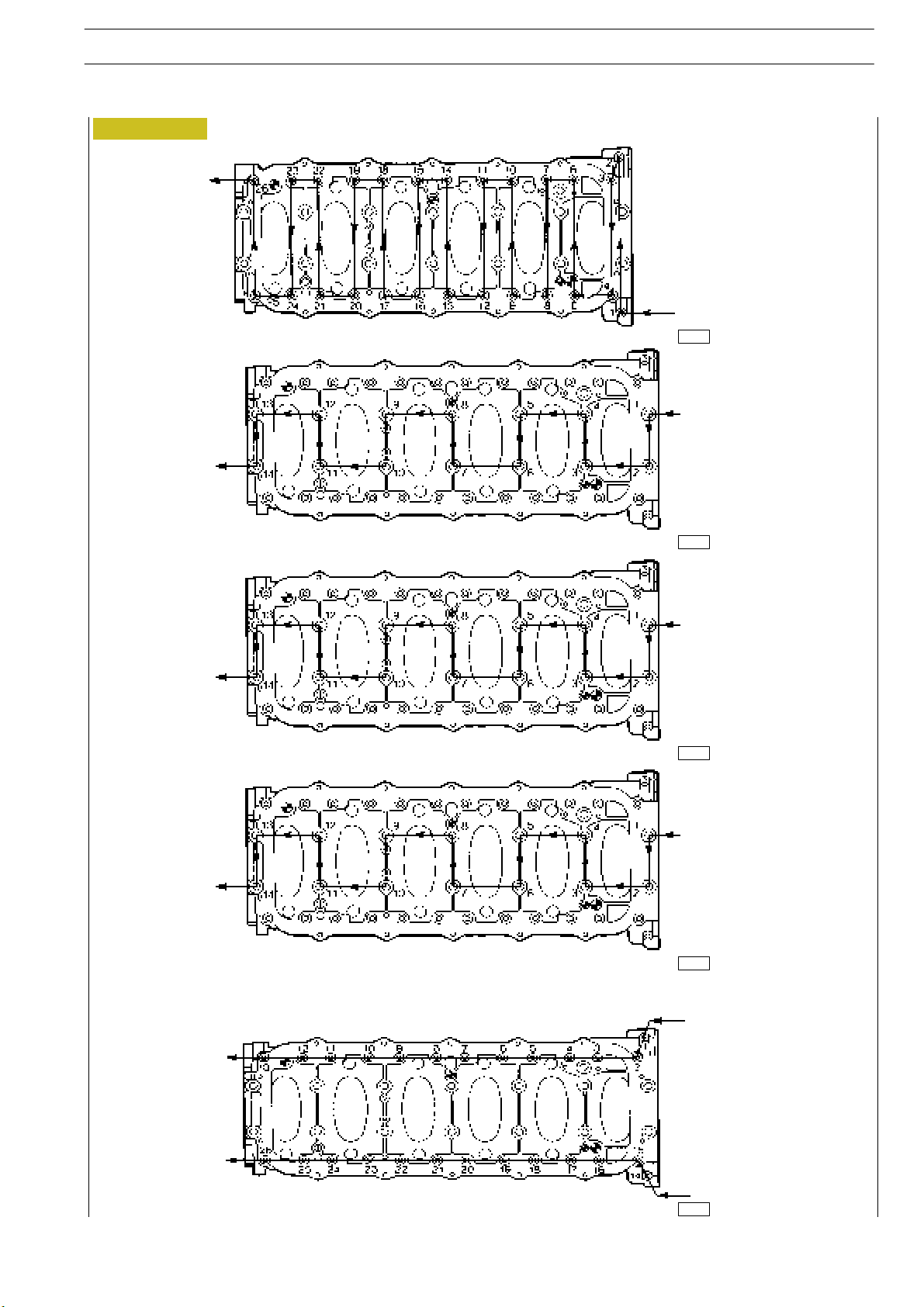
Under-basement fastening screws to cylinder block (see Figure 6) ♦
Outer screws First stage : pre-tightening M10x1.25 25 2.5
Inner screws Second stage : pre-tightening M16x2 140 14
Inner screws Third stage : angle closing M16x2 60°
Inner screws Fourth stage : angle closing M16x2 60°
Outer screws Fifth stage : angle closing M10x1,5 90°
Pipe un i on for piston cooling nozzle M12X1.5
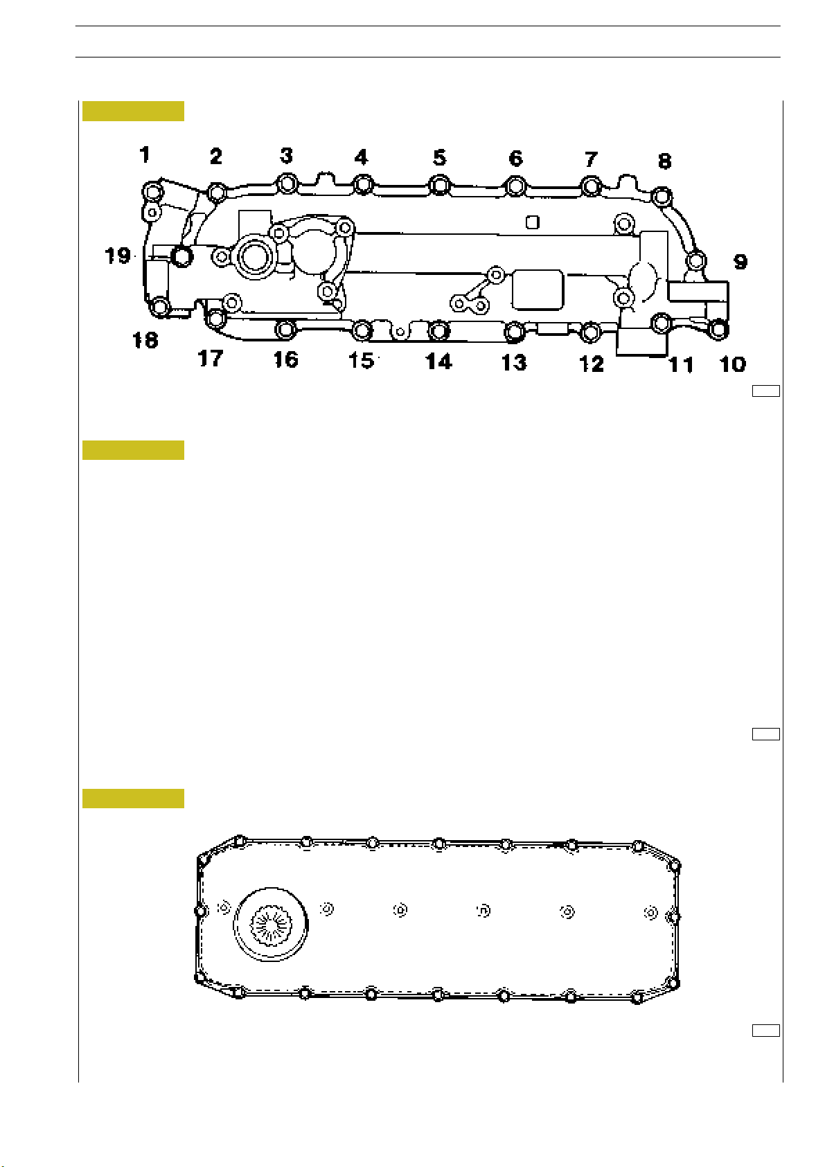
Intercooler fastening screws to cylinder block ♦ (see Figure 10)
pre-tightening
tightening
Plug 125 ± 15 12.5 ± 1.5
Spacer and oil sump fastening screws (see Figure 11) 41.5 ± 3.5 4.1 ± 0.3
Gearcase fastening screws to cylinder block 41.5 ± 3.5 4.1 ± 0.3
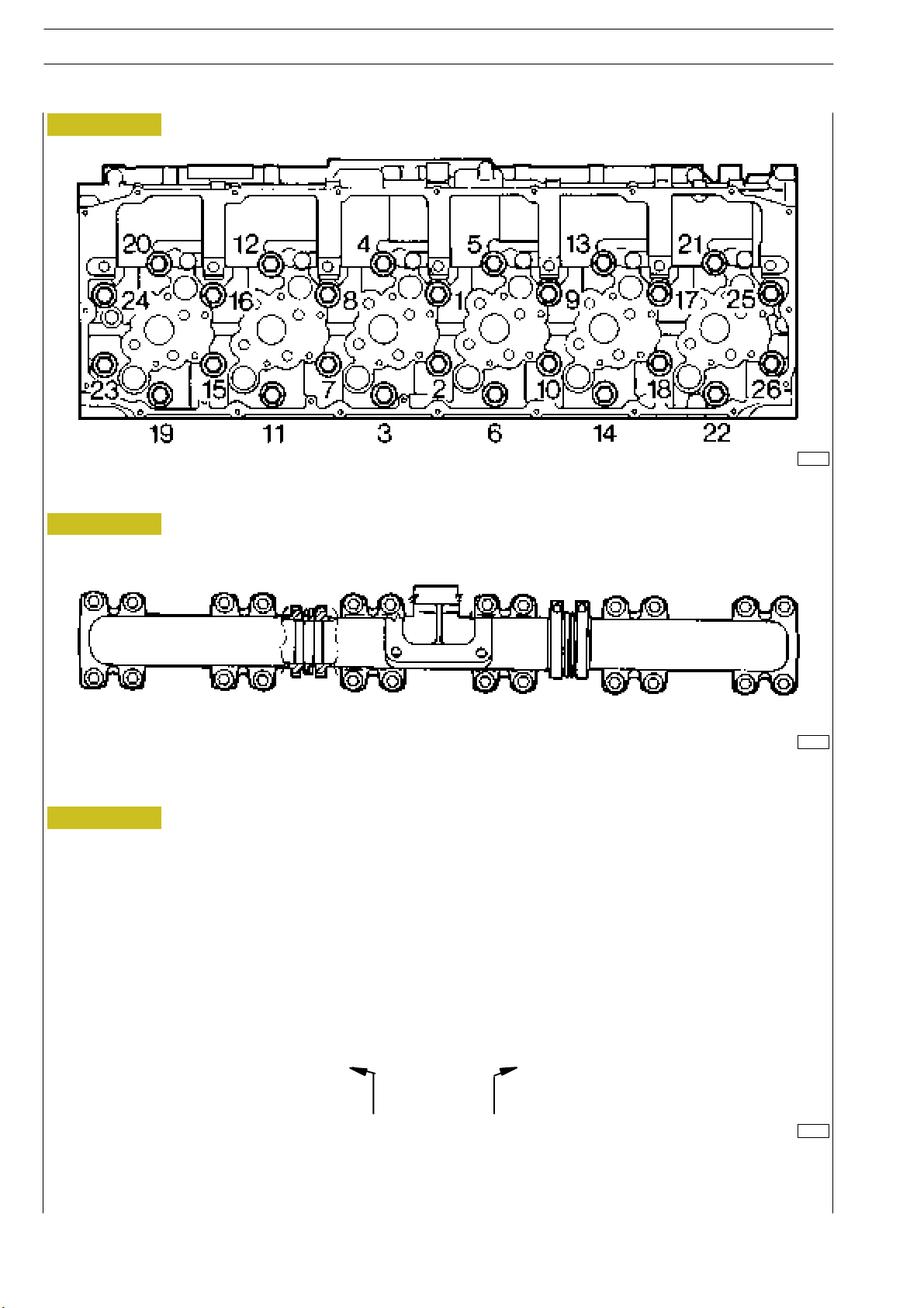
Cylinder head fastening screw: (see Figure 7) ♦
First stage pre-tighteni ng 50 5
Second stage pre-tightening 100 10
Third stage angle closing 90°
Fourth stage angle closing 75°
Rocker arm shaft fastening screw ♦
First stage pre-tighteni ng 40 4
Second stage pre-tightening 60°
Locknutforrockerarmadjustingscrew♦
Screws for injector fastening brackets ♦ 36.5 3.65
Shoulder plate fastening screws to head ♦ 23.5 2.35
Engine support bracket fastening screws to cylinder head 74 ± 8 7.4 ± 0.8
Gear fastening screws to camshaft: ♦
First stage pre-tighteni ng 50 5
Second stage pre-tightening 50°
Phonic wheel fastening screws to distribution gear 8.5 ± 1.5 0.8 ± 0.1
Exhaust pipe fastening screws • (see Figure 8)
pre-tightening
tightening
Engine brake actuator cylinder fastening sc rews 24.5 ± 2.5 2.4 ± 0.2
Connecting rod cap fastening screws: ♦
First stage pre-tighteni ng 50 5
Second stage pre-tightening 40°
Engine flywheel fastening screws: ♦ M16x1.5x58
First stage pre-tightening 100 10
Second stage pre-tightening 60°
Engine flywheel fastening screws: ♦ M16x1.5x110
First stage pre-tightening 100 10
Second stage pre-tightening 120°
Flywheel pulley fastening screws to crankshaft : ♦
First stage pre-tighteni ng 70 7
Second stage pre-tightening 50°
♦ Lubricate with oil MOLYKOTE before assembly
• Lubricate with graphitized oil before assembly
35 ± 2 3.5 ± 0.2
11.5 ± 3.5
19 ± 3
1.15 ± 0.35
1.9 ± 0.3
63 ± 76.3± 0.7
9 ± 31.9± 0.3
39 ± 5 3.9 ± 5
32.5 ± 7.5
47 ± 2.5
3.2 ± 0.7
4.7 ± 0.2
Base - January 2003 Print 603.93.141
Page 48

STRALIS AT/AD
ENGINE F2B
TIGHTENING TORQUES
PART TORQUE
Nm kgm
Damper flywheel fastening screws: ♦ 115 ± 15 11.5 ± 1.5
Idler gear pin fastening screws: ♦
First stage pre-tighteni ng 30 3
Second stage pre-tightening 90°
Idle gear link rod fastening screw
Oil pump fastening screw 24.5 ± 2.5 2.4 ± 0.2
Oil pump suction rose fastening screw 24.5 ± 2.5 2.4 ± 0.2
Front cover fastening screw to cylinder block ♦ 19 ± 3 1.9 ± 0.3
Control unit fastening screw to cylinder block ♦ 19 ± 3 1.9 ± 0.3
Supply pump fastening screw to gearcase ♦ 19 ± 3 1.9 ± 0.3
Fuel filter support fastening screw to cylinder head ♦ 37 ± 3 3.7 ± 0.3
Turbo-compressor fastening screws and nuts • (see Figure 9)
pre-tightening
tightening
Water pump fastening screw to cylinder block 24.5 ± 2.5 2.4 ± 0.2
Pulley fastening screw to hub 55 ± 5 5.5 ± 0.5
Rocker arm cover fastening screws (see Figure 12) 9 0.9
Thermostat box fastening screws to c ylinder head 24.5 ± 2.5 2.4 ± 0.2
Automatic tightener fastening screws to cylin der block 45 ± 5 4.5 ± 0.5
Fixed tightener fastening screws to cylinder block 105 ± 5 10.5 ± 0.5
Fan support fastening screws t o cylinder block 24.5 ± 2.5 2.4 ± 0.2
Starter fastening screws 44 ± 4 4 ± 0.4
Airheateroncylinderhead 30 ± 3 3 ± 0.3
Aircompressorfasteningscrewtocylinderhead 74 ± 8 7.4 ± 0.8
Air compressor control gear fastening nut 170 17 ± 1
Hydraulic power steering pump gear fastening nut 46.5 ± 4.5 4.6 ± 0.4
Air conditioner compressor fastening screw to support 24.5 ± 2.5 2.4 ± 2.5
Air conditioner compressor support fastening screw to cylinder block 44 ± 4 4.4 ± 0.4
Alternator support fastening screw to cylinder block 44 ± 4 4.4 ± 0.4
Alternator bracket fastening screw to cylinder block 24.5 ± 2.5 2.4 ± 0.2
Water pipe unions 35 3.5
Water temperature sensor 32.5 ± 2.5 3.2 ± 0.2
♦ Lubricate with oil MOLYKOTE before assembly
• Lubricate with graphitized oil before assembly
24.5 ± 2.5 2.4 ± 0.2
32.5 ± 7.5
46 ± 2
3.2 ± 0.7
4.6 ± 0.2
23
Print 603.93.141 Base - January 2003
Page 49

24
ENGINE F2B
S
TRALIS AT/AD
TIGHTENING TORQUES
PART TORQUE
Nm kgm
Engine brake solenoid valve fastening screws 32.5 ± 2.5 3.2 ± 0.2
Flywheel rev sensor fastening screw 8 ± 4 0.8 ± 0.2
Camshaft rev sensor fastening screw 8 ± 2 0.8 ± 0.2
P.D.E solenoid connector fastening screw 1.62 ± 0.3 0.1 ± 0.3
Overboost pressure sensor fastening screw 8 ± 2 0.8 ± 0.2
Absolute pressure sensor fastening screw 22.5 ± 2.5 2.2 ± 0.2
P.W.M. control valve fastening screw/nut 8 ± 2 0.8 ± 0.2
Fuel/coolant temperature sensor 35 3.5
Coolant temperature indicator 23.5 ± 2.5 2.3 ± 0.2
Filter clogging sensor 10 1
Oil temperature switch 25 ± 1 2.5 ± 0.1
Oil pressure sensor 25 ± 1 2.5 ± 0.1
Oil clogging sensor 55 ± 5 5.5 ± 0.5
Electric wire fastening screw 8 ± 2 0.8 ± 0.2
Heater fastening screw 12.5 ± 2.5 1.2 ± 0.2
Base - January 2003 Print 603.93.141
Page 50
STRALIS AT/AD
UNDERBLOCK FIXING SCREWS TIGHTENING SEQUENCE
Figure 6
ENGINE F2B
25
FRONT SIDE
FRONT SIDE
FRONT SIDE
First phase:
preliminary t ightening
of outer screws
(25 Nm)
44897
Second phase:
preliminary
tightening of
inner screws
(140 Nm)
44898
Third phase:
angle tightening
of inner screws
60º
FRONT SIDE
FRONT SIDE
44898
Front phase:
angle tightening
of inner screws
60º
44898
Fifth phase:
angle tightening
of outer screws
90º
44899
Print 603.93.141 Base - January 2003
Page 51
26
ENGINE F2B
Figure 7
DIAGRAM OF CYLINDER HEAD FIXING SCREWS TIGHTENING SEQUENCE
S
TRALIS AT/AD
44900
Figure 8
18
63 27 63 47 63 27
DIAGRAM OF EXHAUST MANIFOLD FIXING SCREWS TIGHTENING SEQUENCE
Figure 9
54852854 11
45359
45360
DIAGRAM OF TURBOCHARGER FIXING SCREWS AND NUTS TIGHTENING SEQUENCE
SEQUENCE: Preliminary tightening 4 - 3 - 1 - 2
Tightening 1-4-2-3
Base - January 2003 Print 603.93.141
Page 52
STRALIS AT/AD
Figure 10
DIAGRAM OF HEAT EXCHANGER FIXING SCREWS TIGHTENING SEQUENCE
ENGINE F2B
27
455361
Figure 11
1
12 11 10 3
14
45672
DIAGRAM OF ENGINE OIL SUMP FIXING SCREWS TIGHTENING SEQUENCE
Figure 12
17 14 13 1 4 5 8
913
8
45362
18
19
20
16 15 12 2 3 6 7
DIAGRAM OF ROCKER ARM CAP FIXING SCREWS TIGHTENING SEQUENCE
Print 603.93.141 Base - January 2003
9
10
11
45363
Page 53
28
ENGINE F2B
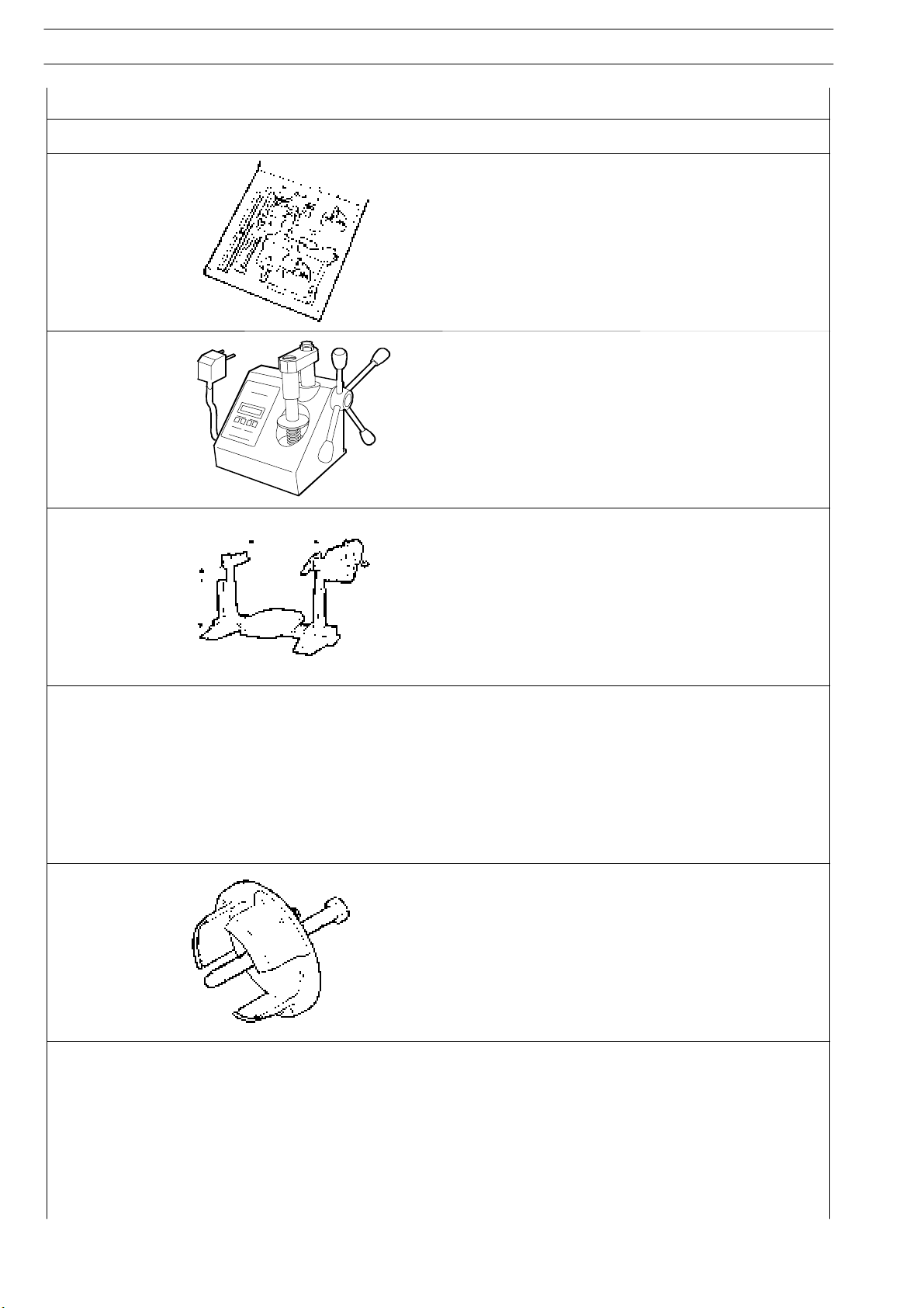
TOOLS
TOOL NO. DESCRIPTION
S
TRALIS AT/AD
99305019
99305047
99322230
Full-optional tool-kit to rectify valve seat
Equipment for spring load check
Rotary telescopic stand
99340051
99340052
99340205
Extractor for cran kshaft front gasket
Extractor for crankshaft rear gasket
Percussion extractor
Base - January 2003 Print 603.93.141
Page 54
STRALIS AT/AD
TOOLS
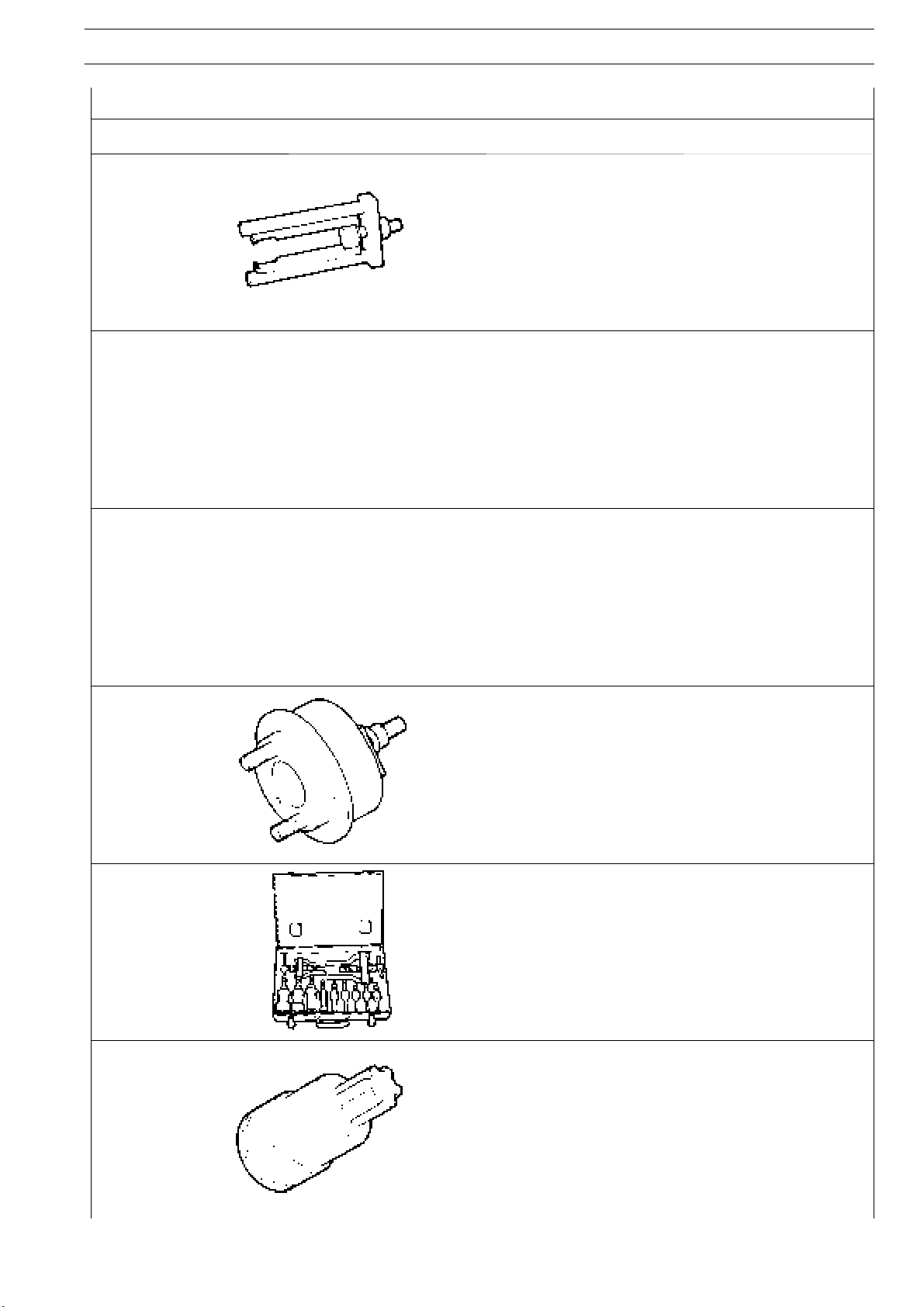
TOOL NO. DESCRIPTION
ENGINE F2B
29
99342148
99342149
99346245
Injector extractor
Extractor for injector-holder
Tool to install the crankshaft front gasket
99346246
99348004
99350072
Tool to install the crankshaft rear gasket
Universal extractor for 5 to 70 mm internal components
Box wren ch for transmission gear support fixing screws
Print 603.93.141 Base - January 2003
Page 55
30
ENGINE F2B
TOOLS
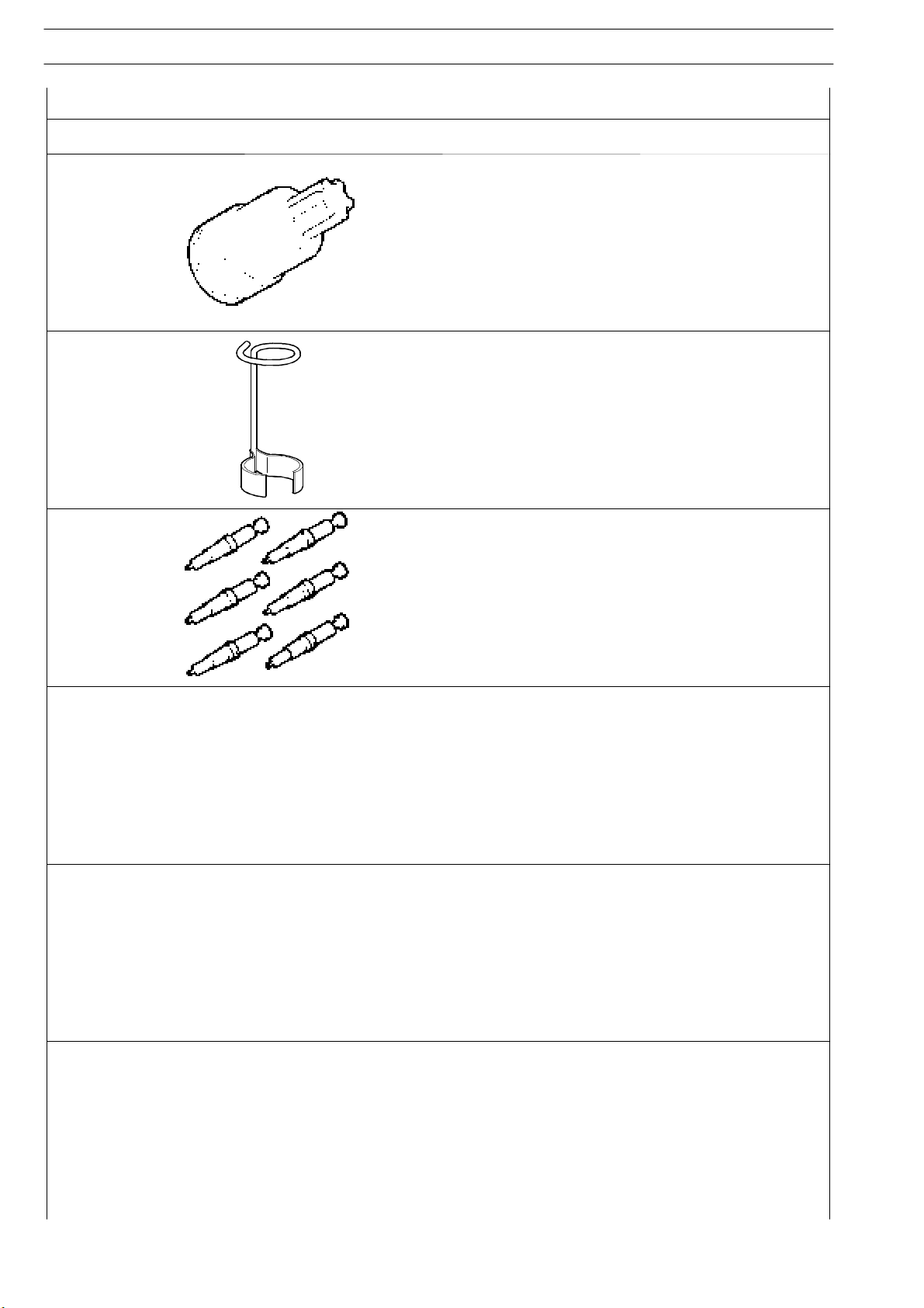
TOOL NO. DESCRIPTION
S
TRALIS AT/AD
99350074
99360144
99360177
Box wrench for block junction bolts to the underblock
Skid retaining tools (12+6) for rocker arm adjusting screws during
rocker arm shaft removal/ refitting
Injector housing plug
99360184
99360264
99360288
Pincers for removing and refitting circlips and pistons
(105-160 mm)
Tool to take down-fit engine valves
Tool to remove valve guide
Base - January 2003 Print 603.93.141
Page 56
STRALIS AT/AD
TOOLS
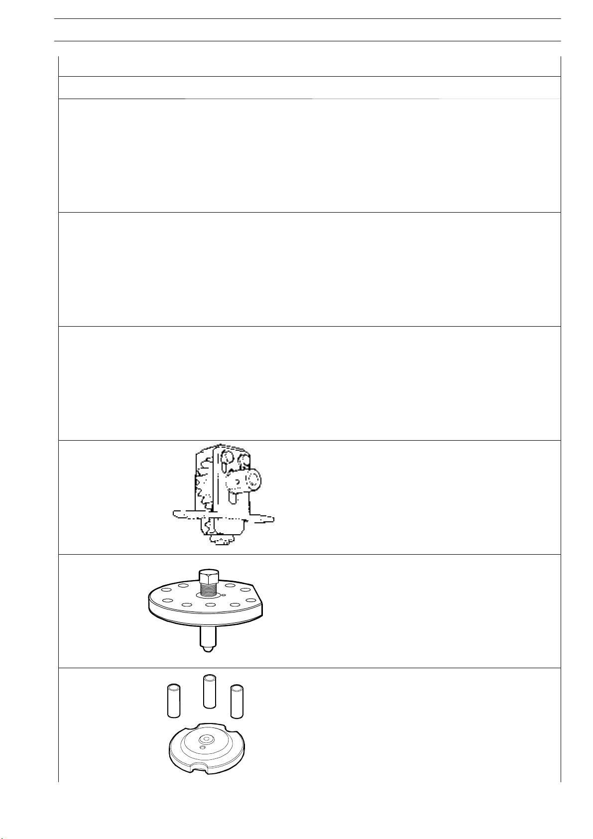
TOOL NO. DESCRIPTION
ENGINE F2B
31
99360292
99360294
99360314
Tool to install gasket on valve guide
Tool to drive valve guide
Tool to remove cartridge filters
99360321
99360334
99360335
Tool to rotate engine flywheel
Tool for checking cylinder barrel projection.
Cylinder barrel compression cap (to be used with 99360334)
Print 603.93.141 Base - January 2003
Page 57
32
ENGINE F2B
TOOLS
TOOL NO. DESCRIPTION
S
TRALIS AT/AD
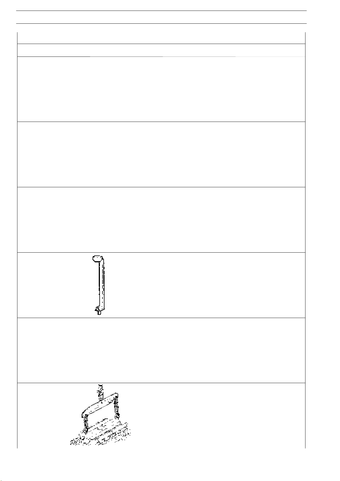
99360351
99360487
99360500
Tool to stop engine flywheel
Tool to take down and fit back camshaft bushes
Tool to lift crankshaft
99360551
99360558
99360585
Bracket to take down and fit engine flywheel
Tool to lift and transport rocker shaft
Balance for lifting and handling engine
Base - January 2003 Print 603.93.141
Page 58
STRALIS AT/AD
TOOLS
TOOL NO. DESCRIPTION
ENGINE F2B
33
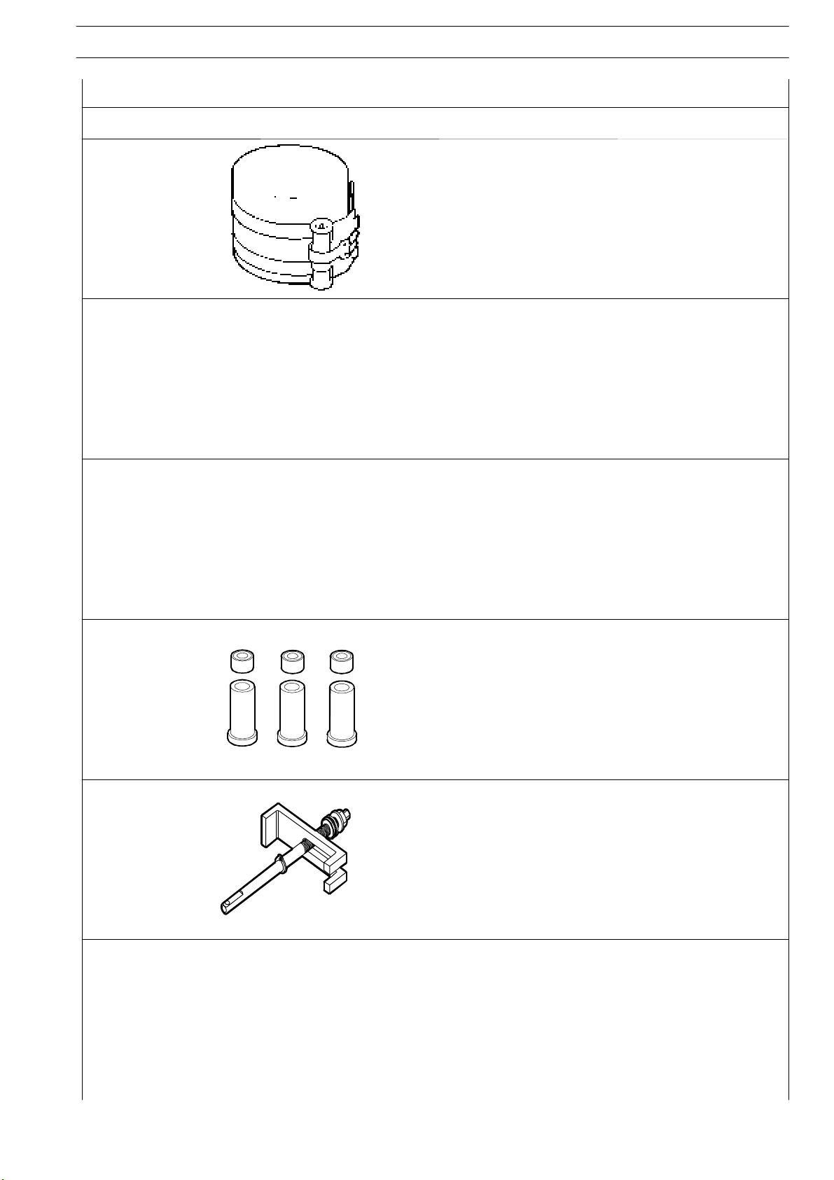
99360605
99360612
99360613
Belt to insert piston in cylinder liner (60 - 125 mm)
Engine flywheel timing pin
Tool for timing of phonic wheel on timing gear
99360703
99360706
99360724
Tool to stop cylinder liners
Tool to extract cylinder liners
Tool to extract the cylinder liners (to be used with 99360723)
Print 603.93.141 Base - January 2003
Page 59
34
ENGINE F2B
TOOLS
TOOL NO. DESCRIPTION
S
TRALIS AT/AD
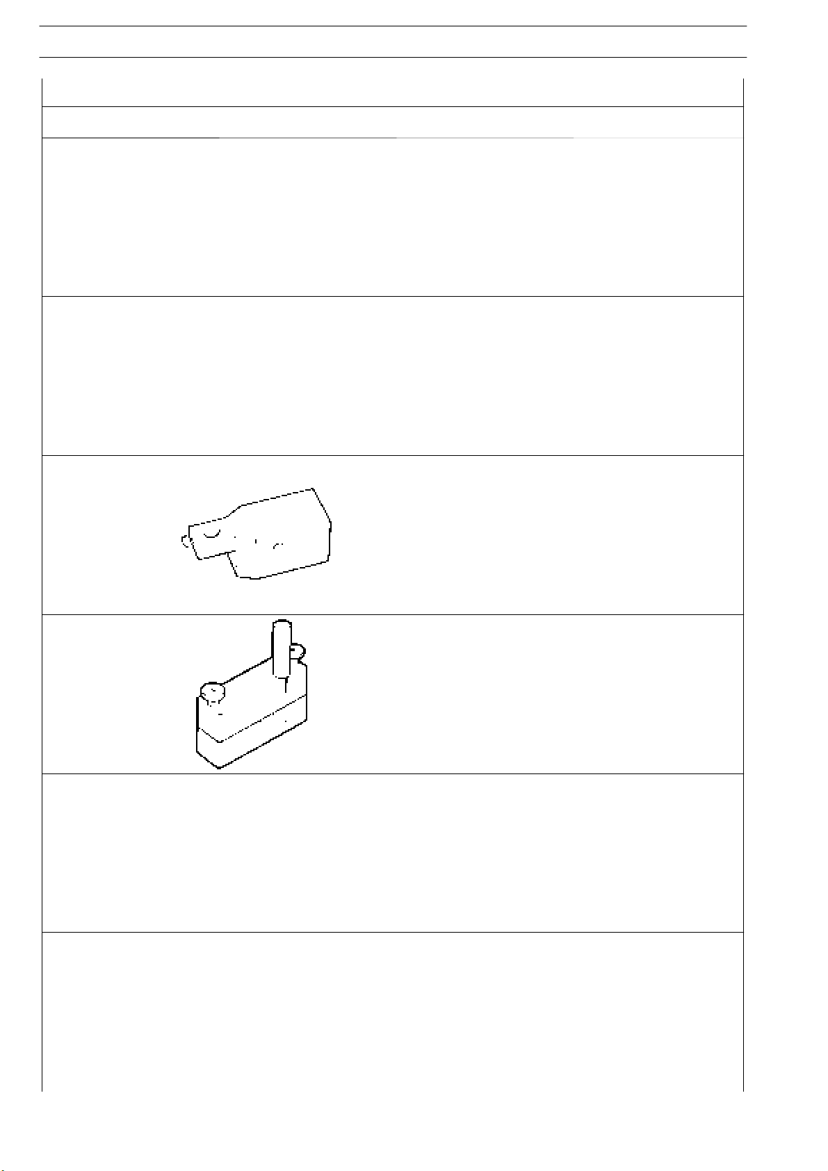
99361035
99365054
99370415
Brackets fixing the engine to rotary stand 99322230
Toolforinjectorholderheading
Tool to detect cylinder liner projections
(use with 99395603)
99378100
99378101
99378102
Tool for printing engine identification plates (to be used with
special punches)
Punches (A) for printing engine identification plates (to be used
with 99378100)
Punches (B) for printing engine identification plates (to be used
with 99378100)
Base - January 2003 Print 603.93.141
Page 60

STRALIS AT/AD
TOOLS
TOOL NO. DESCRIPTION
ENGINE F2B
35
99378105
99378106
99389834
Punches (E) for printing engine identification plates (to be used
with 99378100)
Punches (F) for printing engine identification plates (to be used
with 99378100)
Dynamometric screwdriver to calibrate screws for injector
solenoid valve
99390310
99390772
99390804
Valve guide sleeker
Tool to remove residues from injector holder
Tool to thread injector holders to be extracted
Print 603.93.141 Base - January 2003
Page 61

36
ENGINE F2B
TOOLS
TOOL NO. DESCRIPTION
S
TRALIS AT/AD
99394014
99394041
99394043
Guide bush (to be used with 99394041 or 99394043)
Cutter to rectify injector holder housing (to be used with
99394015)
Reamer to rectify injector holder lower side (to be used with
99394015)
99395215
99395216
99395363
Gauge for centre distance check between camshaft and idle gear
Measuring pair for angular tightening with 1/2” and 3/4” square
couplings
Complete square to check connecting rod squaring
Base - January 2003 Print 603.93.141
Page 62
STRALIS AT/AD
TOOLS
TOOL NO. DESCRIPTION
ENGINE F2B
37
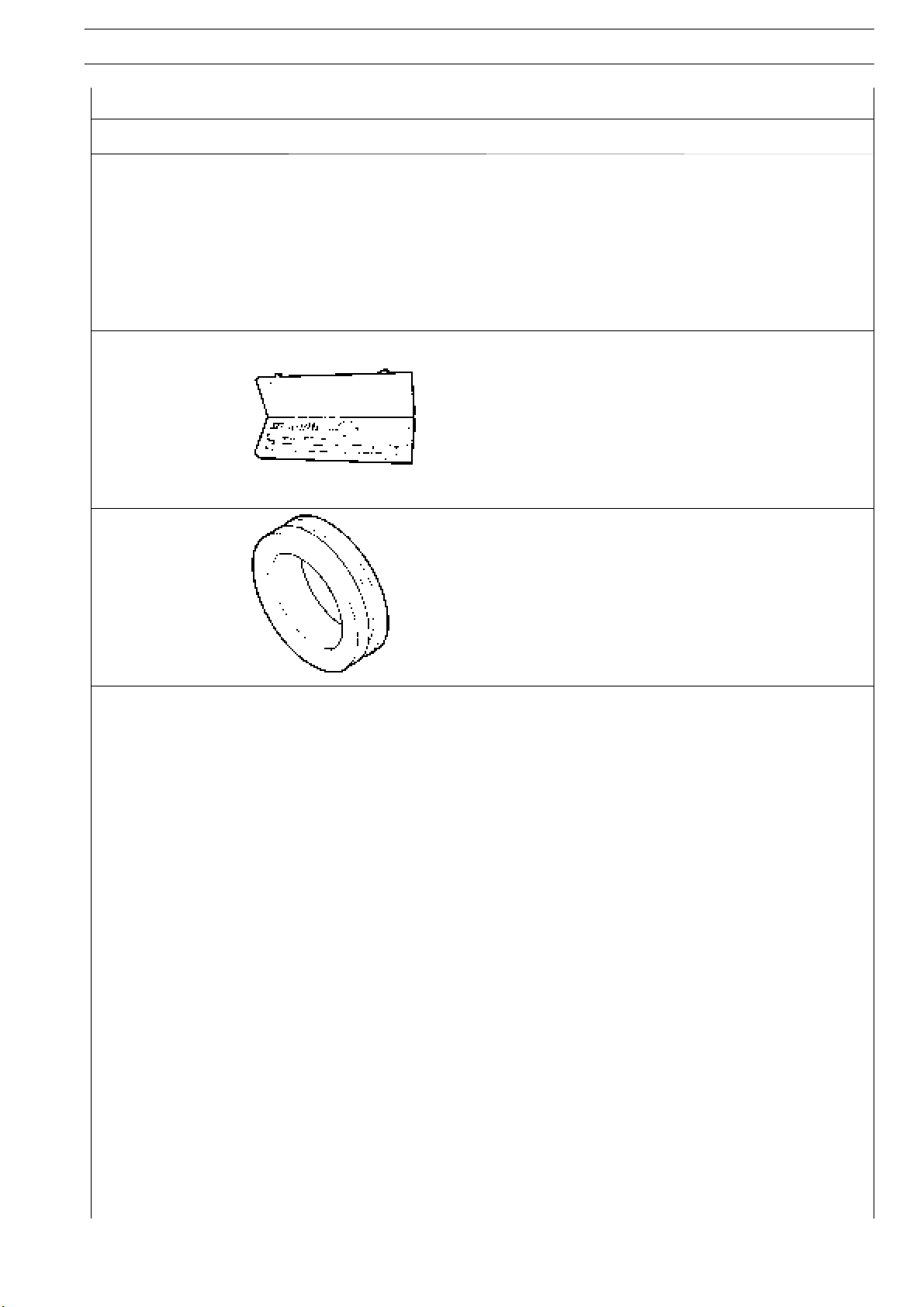
99395603
99395687
99396033
Dial gauge (0 - 5 mm)
Reaming gauge (50-178 mm)
Centering ring of crankshaft front cap
Print 603.93.141 Base - January 2003
Page 63
38
ENGINE F2B
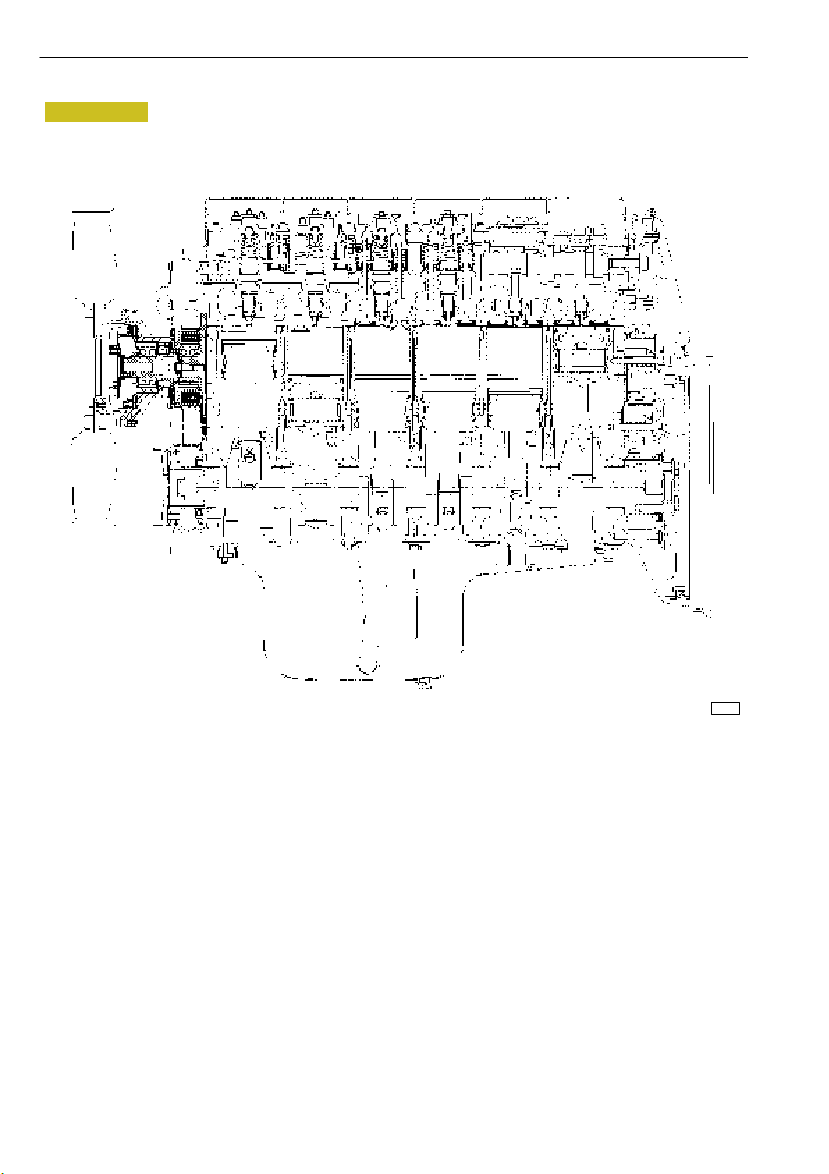
Figure 13
S
TRALIS AT/AD
ENGINE - LONGITUDINAL SECTION
78839
Base - January 2003 Print 603.93.141
Page 64
STRALIS AT/AD
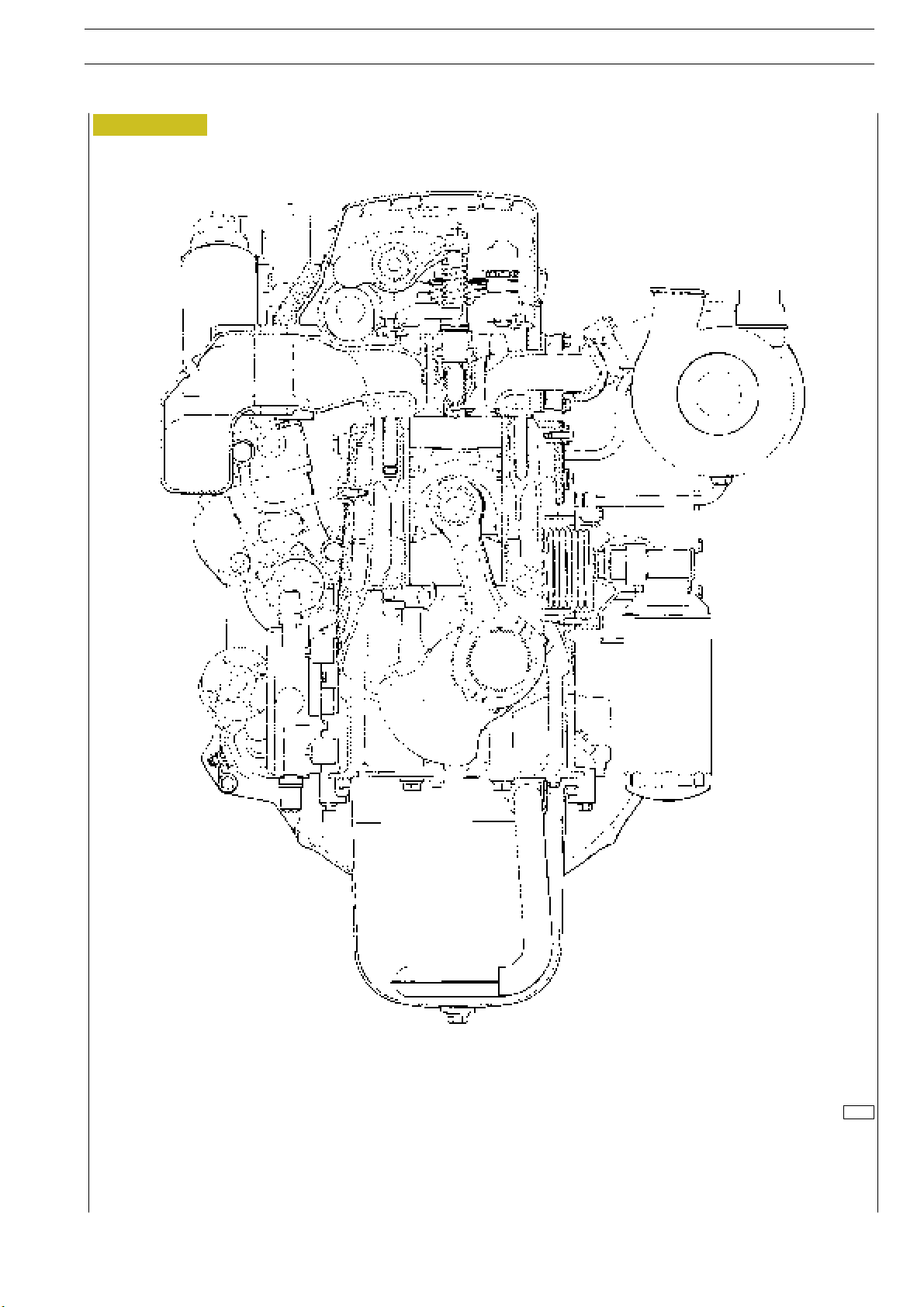
Figure 14
ENGINE F2B 39
78841
ENGINE - CROSS SECTION
Print 603.93.141 Base - January 2003
Page 65
40
ENGINE F2B
54010 DISMANTLING THE ENGINE
ON THE BENCH
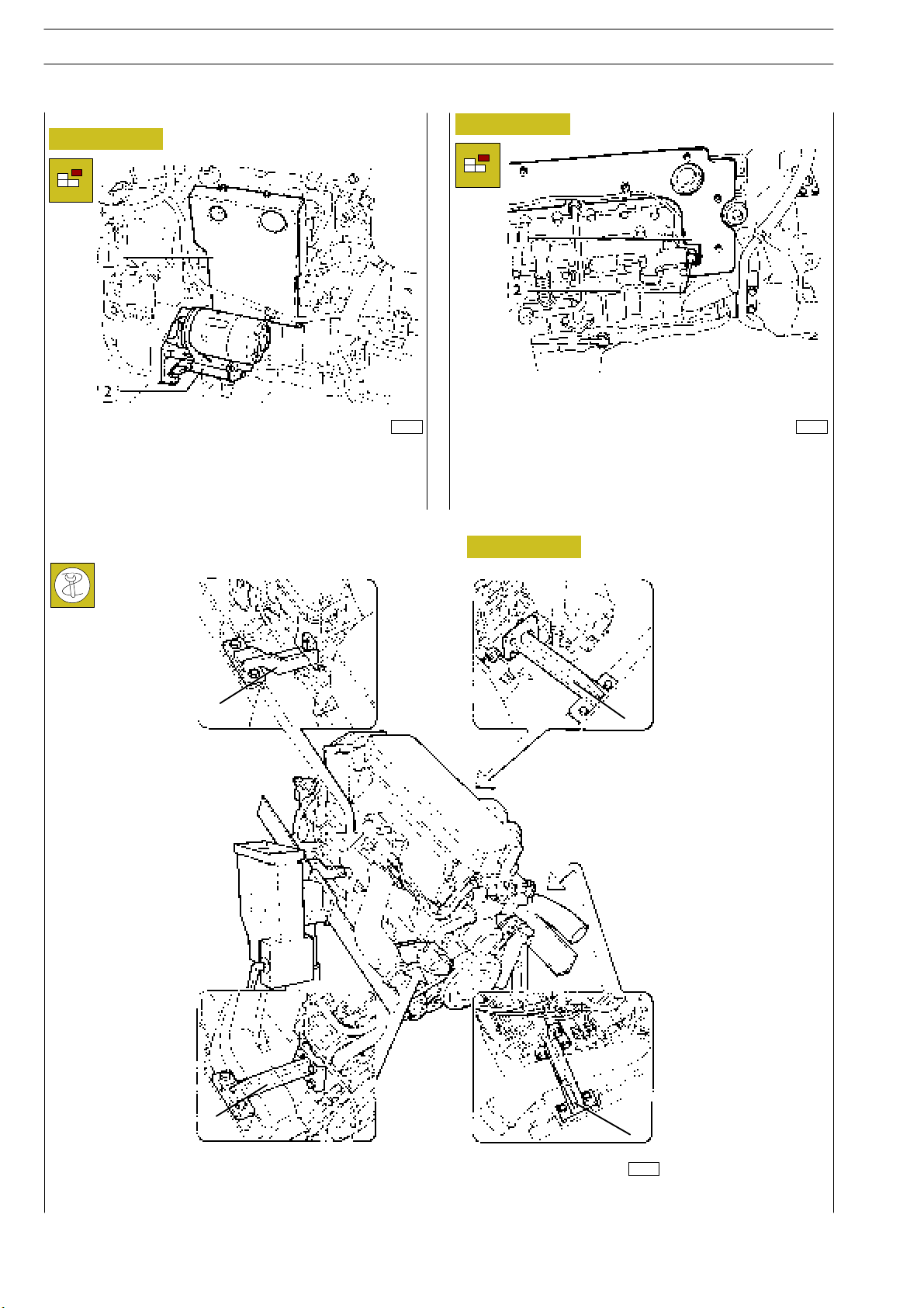
Figure 15
Before dismantling the engine on the rotary stand 99322230,
remove the following components:
- starter (2)
- turbocharger soundproofing shield (1)
TRALIS AT/AD
S
Figure 16
47562 47563
Remove the soundproofing shield (1) and plug (2)
Figure 17
1
1
1
1
47601
Fix the engine to the rotary stand 99322230, by means of
brackets 99361035 (1), remove the fan.
Base - January 2003 Print 603.93.141
Page 66
STRALIS AT/AD
ENGINE F2B 41
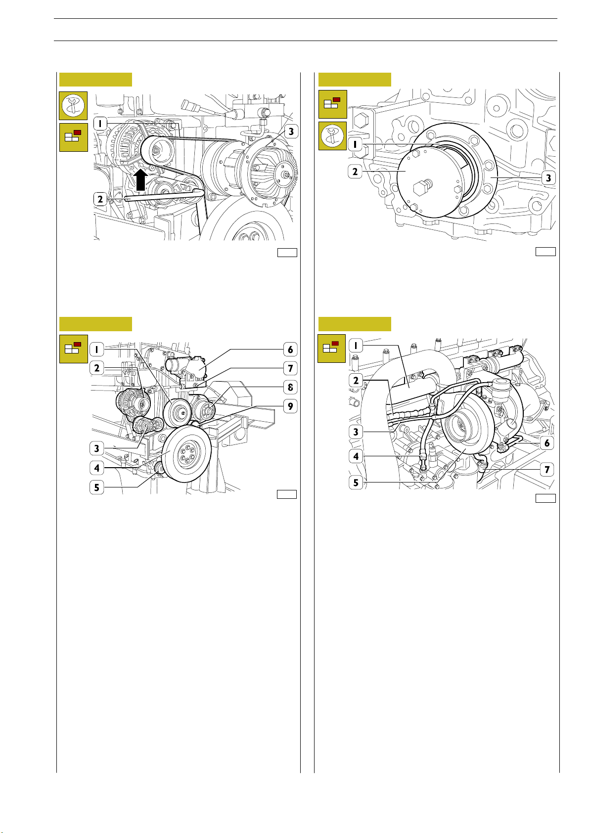
Figure 18
73579
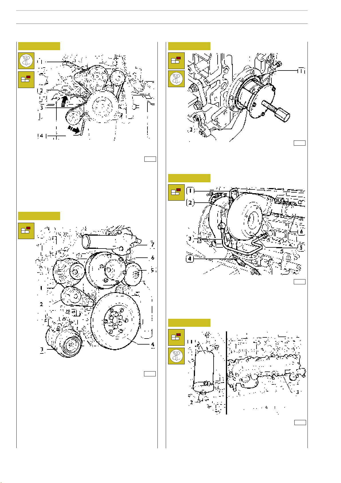
Using an appropriate tool (2), operate in the direction of the
arrow, and remove the belt (1) driving the water pump,
alternator and fan.
Take out the sc rew s and remove the electromagnetic
coupling (3).
Figure 19
Figure 20
60490
Fit the extractor 99340053 (2) and remove the engine
crankshaft seal gasket (1), remove the cover (3).
Figure 21
60489
Remove the following components:
- thermostat unit (6) fitted with turbine actuator pressure
sensor (7);
-alternator(2);
- pulley support (1);
- water pump (8) and piping;
- automatic belt tightener support (3);
- fixed belt tightener (9);
- damping flywheel (4) and pulley underneath it;
- automatic belt tightener (5);
- disconnect all the electric connections and the sensors.
60491
Remove the following components:
- water outlet line (2);
- oil delivery line (4);
- actuator air line (3);
- water delivery line (6);
- oil return line (7);
- turbocharger (5);
- exhaust manifold (1).
Print 603.93.141 Base - January 2003
Page 67
42
ENGINE F2B
TRALIS AT/AD
S
Figure 22
47564
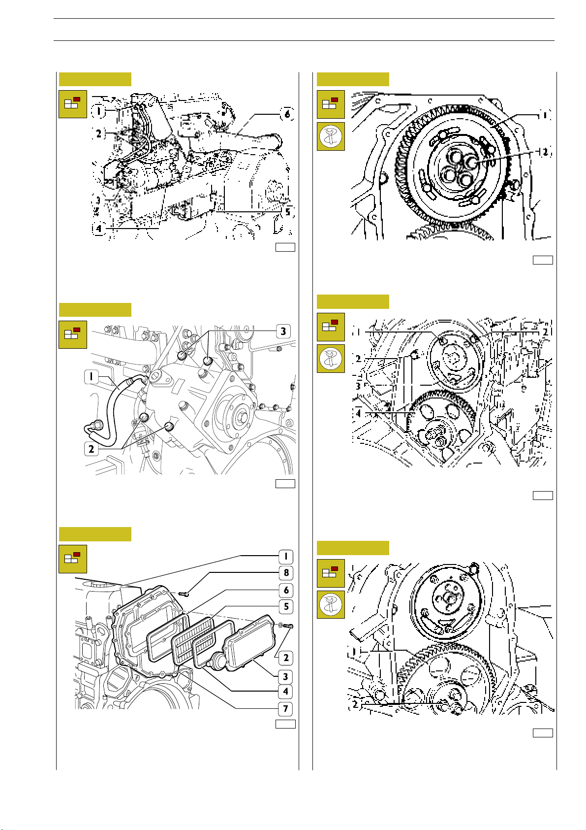
Load the belt tensioner spring by tool (4), acting in the
direction shown by the arrow, on the head of the screw fixing
the roller. The screw cannot be untightened as the thread is
counterclock-wise. Remove the belt (3). By tool (2), act in the
direction shown by the arrow and remove the fan, alternator
and water pump control belt (1).
Figure 24
45254
Install extractor 99340051 (2) and remove the seal gaskets
(1). Unscrew the screws and remove the cover.
Disconnect all electric connections and sensors.
Figure 25
Figure 23
Remove the following components:
-alternator(1);
- belt tightener support (2);
- air conditioner compressor (3);
- flywheell (4);
- water pump and piping (5);
- fan pulley spacer (6);
- thermostat unit (7).
47566
Remove the following components: oil supply lines (1); water
cooling supply lines (3); water discharge lines (2); oil return
lines (4); turbocharger (5); exhaust manifold (6).
Figure 26
47565
47567
Unscrew the oil filter (1) by tool 99360314 (2).
Unscrew the screws and remove the entire heat exchanger
(3).
Base - January 2003 Print 603.93.141
Page 68
STRALIS AT/AD
ENGINE F2B 43
Figure 27
47587
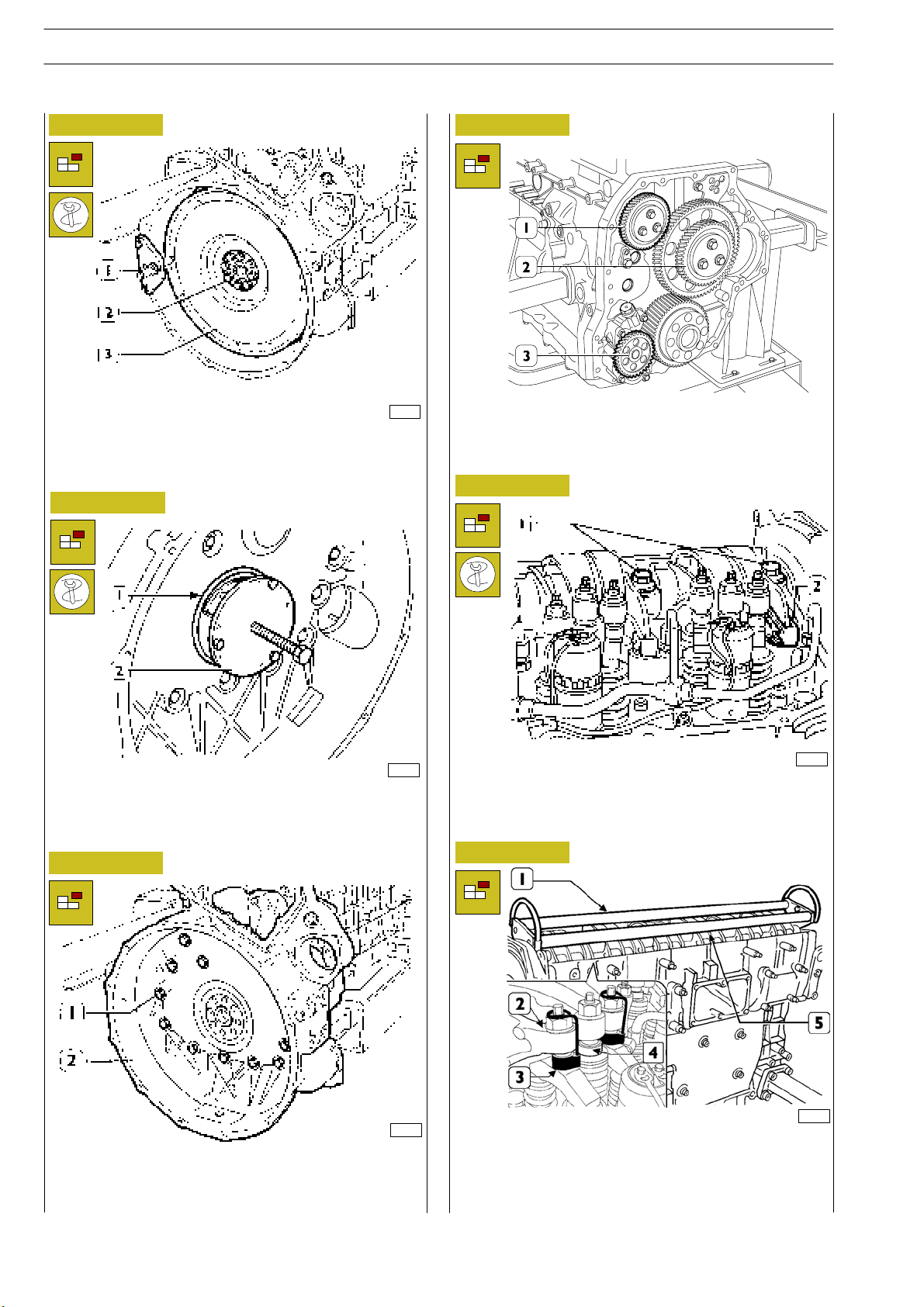
Remove the following components: intake manifold (6);
support for fuel filter (1); fuel lines (2); fuel pump
(3);compressor (4); control unit (5).
Figure 28
Figure 30
45661
Unscrew the screws (2), by using the proper wrench and
remove the gear (1) with the phonic wheel.
Figure 31
70708
To remove the P.T.O. (if applicable):
- Disconnect the oil pipe (1).
- Unscrew the 4 screws (2) and (3).
Figure 29
84377
Remove the rocker arm cover (1), take off the screws (2) and
remove: the cover (3), the filter (5) and the gaskets (4 and 6).
Take off the screws (8) and remove the blow-by case (7).
45265
Unscrew the screws (1); tighten a screw in a reaction hole and
remove the shoulder plate (3), remove the sheet gasket.
Figure 32
47568
By means of a properly splined wrench, untighten screws (2)
and remove the transmission gear (1)
Print 603.93.141 Base - January 2003
Page 69
44
ENGINE F2B
TRALIS AT/AD
S
Figure 33
47568
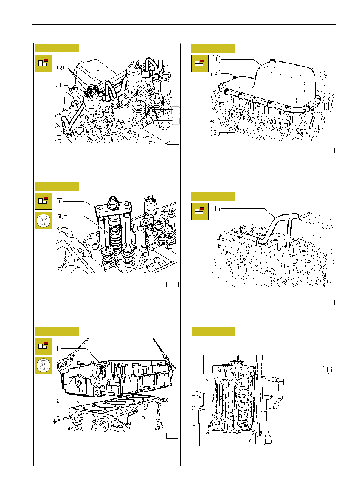
Stop the engine flywheel (3) rotation by means of tool
99360351 (1), untighten the fixing screws (2) and remove the
engine flywheel.
Figure 34
Figure 36
In sequence, take out the:
- if the P.T.O. control gear (1) is present;
- idle gear (2);
- oil pump gear (3).
Figure 37
45257
Apply extractor 99340052 (2) and pull out the seal gasket (1).
Figure 35
47569
Untighten the screws (1) and take down the gear box (2).
45259
- Remove the check springs (2) of the exhaust brake lever;
- Untighten the fixing screws (1) of rocker arm shaft.
Figure 38
73533
- Using tool 99360144 (3), constrain the blocks (4) to the
rockers (2).
- Apply tool 99360553 (1) to the rocker holder shaft (5)
and remove the shaft (5) from the cylinder head.
Base - January 2003 Print 603.93.141
Page 70
STRALIS AT/AD
ENGINE F2B 45
Figure 39
45262
- Remove the piping (1) for exhaust brake pins;
- Untighten screws and remove electric connections (2)
from solenoid valves;
- Untighten fixing screws (3) of injector brackets (4).
Figure 40
Figure 42
3
4
47573
Untighten screws (2) and remove the engine oil sump (1) with
spacer (3) and seal .
Figure 43
45263
- Remove injectors (2)
If this operations is difficult, use extractor 99342148 (1). Install
plugs 99360177 instead of injectors.
Figure 41
45266
Remove the camshaft and the fixing screws on cylinder heads
- By means of wire ropes, lift the cylinder head (1) and
remove seals (2).
47572
Untighten screws and remove suction rose (1).
Figure 44
47574
Rotate the block (1) to the vertical position.
Print 603.93.141 Base - January 2003
Page 71
46
ENGINE F2B
TRALIS AT/AD
S
Figure 45
47575
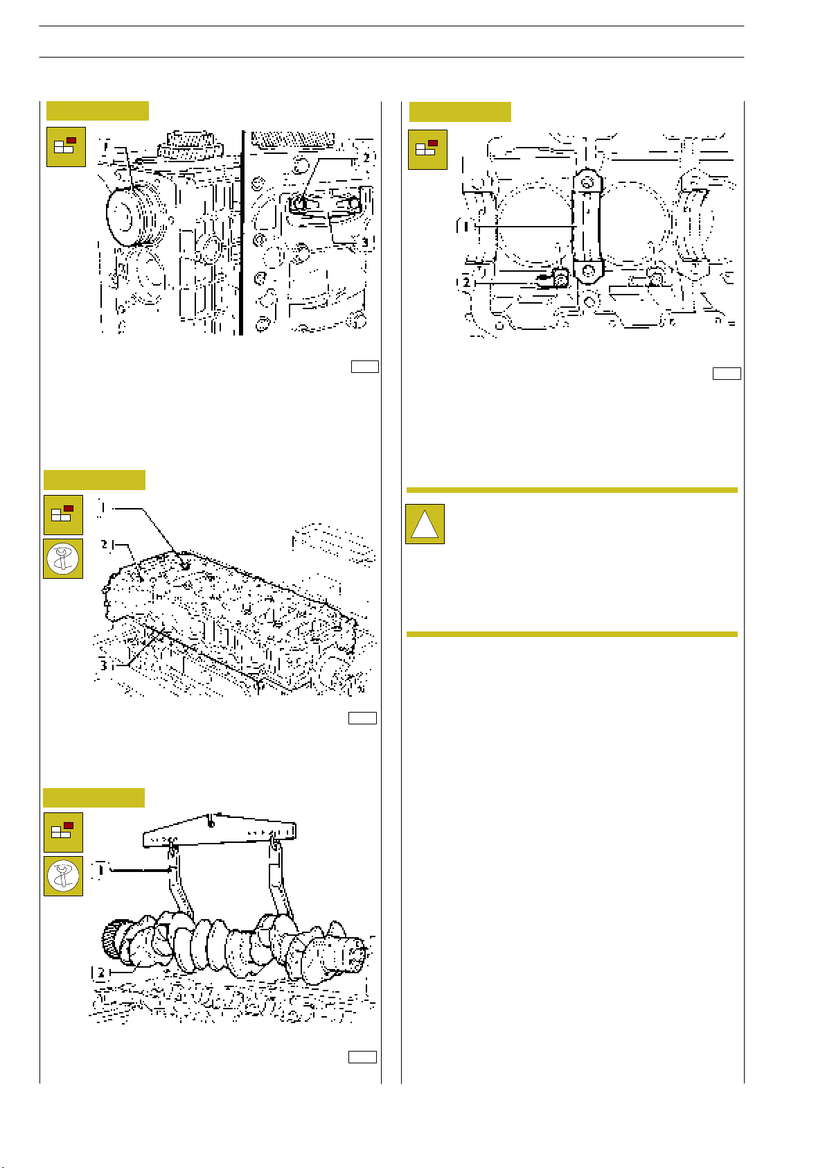
Untighten screws (2) fixing the connecting rod cap (3) and
remove it. Remove the connecting rod-piston assembly from
the upper side. Repeat these operations for the other pistons.
Figure 46
Figure 48
47571
Remove the crankshaft half-bearings (1), untighten the screws
and remove oil spray nozzles (2).
Take down cylinder liners as specified in the relative paragraph
on page 49.
After disassembling the engine, thoroughly clean
disassembled parts and check their integrity.
!
Instructions for main checks and measures are given
in the following pages, in order to determine whether
the parts can be re-used.
47576
By means of proper and splined wrenches, untighten the
screws (1) and (2) and remove the under-block (3).
Figure 47
47570
Remove the crankshaft (2) with tool 99360500 (1).
Base - January 2003 Print 603.93.141
Page 72
STRALIS AT/AD
REPAIR OPERATIONS
540410 CYLINDER BLOCK 540420 Checks and measurements
Figure 49
(Demonstration)
Figure 51
ENGINE F2B
47
34994
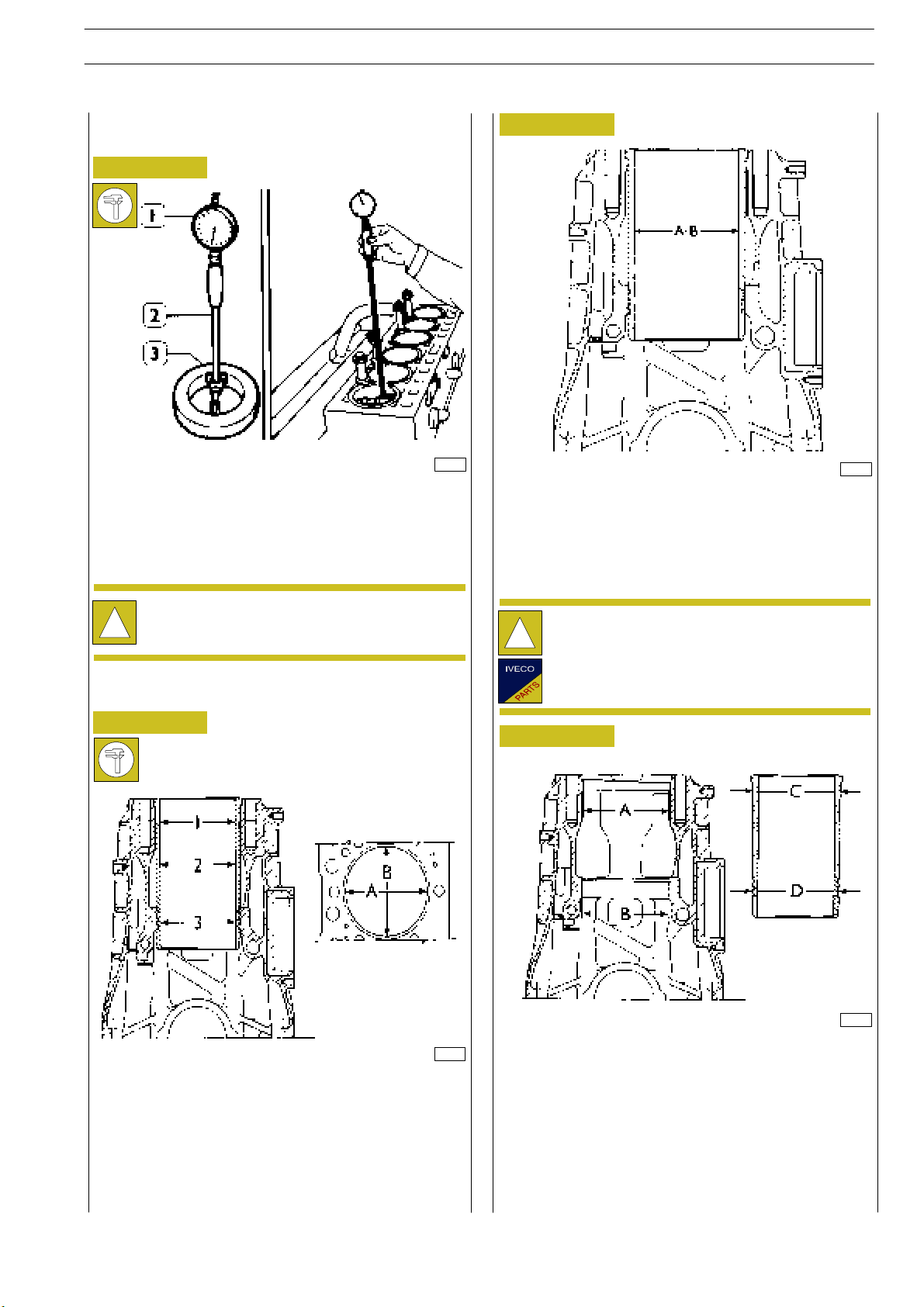
Internal diameter of the cylinder liners is checked for
ovalization, taper and wear, using a bore dial (1) centesimal
gauge 99395687 (2) previously reset to ring gauge (3),
diameter 115 mm.
If a 115 ring gauge is not available use a micrometer
caliper.
!
Figure 50
47440
A = Selection class Ø 115 to 115.012 mm
B = Selection class Ø 115.010 to 115.022 mm
In case of maximum wear max 0.150 mm or maximum
ovalization max 0.100 mm compared to the values indicated
in the figure, the liners must be replaced as they cannot be
ground, lapped or trued.
!
Cylinder liners are equipped with spare parts with
“A“ selection class.
Figure 52
47441
47439
A = Ø 130.200 to 130.225 mm
B = Ø 128.510 to 128.535 mm
1=1stmeasuring
2=2ndmeasuring
3=3rdmeasuring
Carry out measurings on each cylinder liner at three different
levels and on two (A-B) surfaces, to one another
perpendicular, as shown in Figure 50.
Print 603.93.141 Base - January 2003
C = Ø 130.161 to 130.186
D = Ø 128.475 to 128.500 mm
The figure shows the outer diameters of the cylinder liners
and the relative seat inner diameters.
The cylinder liners can be extracted and installed several
times in different seats, if necessary.
Page 73
48
ENGINE F2B
CYLINDER LINERS
Figure 53
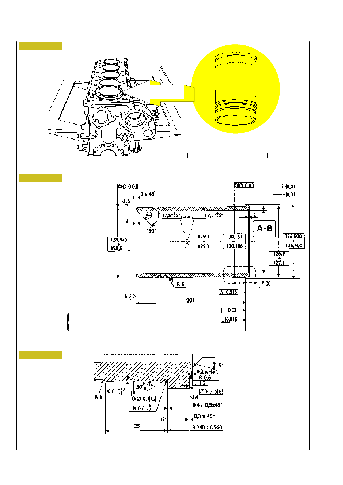
Figure 54
45150 45150a
BLOCK WITH CYLINDER LINERS
S
TRALIS AT/AD
47533
Selection class
A mm 115.000 to 115.012
B mm 115.010 to 115.022
CYLINDER LINERS MAIN DATA
Figure 55
A
47534
DETAIL “X”
“A“ = Selection class marking area
Base - January 2003 Print 603.93.141
Page 74
STRALIS AT/AD
540420 Replacing cylinder liners
Removal
Figure 56
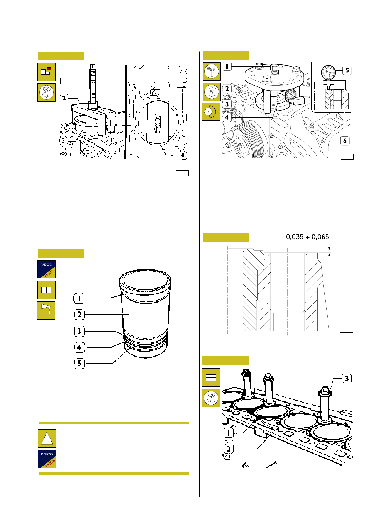
Place details 99360706 (1 and 2) and plate 99360724 (4) as
shown in the figu re, by making sure that the plate (4) is
properly placed on the cylinder liners.
Tighten the screw nut (1) and remove the cylinder liner (3)
from the block.
47577
ENGINE F2B
49
Figure 58
77812
Check cylinder barrel protrusion with tool 99360334
(1-2-3-4) and tighten screw (1) to 170 Nm.
With dial gauge 99395603 (5) placed on base 99370415 (6).
Measure the cylinder barrel protrusion compared to the
cylinder head supporting plane, it must be 0,035 to 0,065 mm
(Figure 59); otherwise replace t he adjusting ring (1,
Figure 57) fitted with spare parts having different thickness.
Fitting and checking protrusion
Figure 57
16798
Always replace water sealing rings (3, 4 and 5).
Install the adjustment ring (1) on the cylinder liner (2);
lubricate lower part of liner and install it in the cylinder unit
using the proper tool.
Figure 59
Figure 60
49017
CYLINDER LINER PROTRUSION
(Demonstration)
!
The adjustment ring (1) is supplied as spare parts in
the following thicknesses: 0.08 mm - 0.10 mm - 0.12
mm.
35012
When the installation is c ompleted, block th e cylinder liners
(1) to the block (2) wit h studs 99360703 (3).
Print 603.93.141 Base - January 2003
Page 75
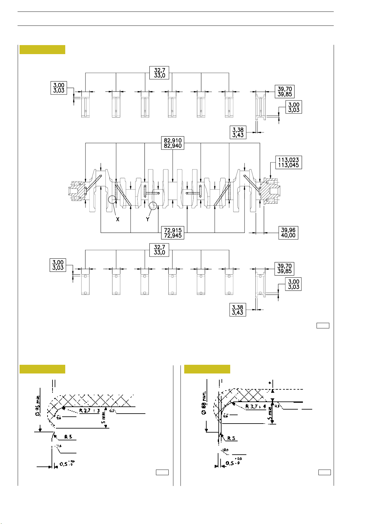
50
ENGINE F2B
5408 CRANKSHAFT
Figure 61
Upper main journal half bearing
S
TRALIS AT/AD
Lower main journal half bearings
49018
MAIN DATA FOR THE CRANK SHAFT PINS AND THE HALF BEARINGS
Check the condition of the journals and the big end pins; there must no be signs of scoring, ovalization or excessive wear.
The data given refer to the normal diameter of the pins.
Figure 62
Figure 63
BUFF
BUFF
47537 47538
X. Detail of main journals connections Y. Detail of crank pins connections
Base - January 2003 Print 603.93.141
Page 76
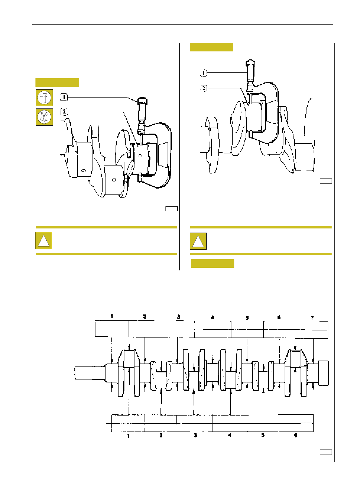
STRALIS AT/AD
540812 Measuring main journals and crank pins
Before grinding the crank pins using a micrometer (1),
measure the main journals and the crank pins (2) and decide,
on the basis of the undersizing of the bearings, the final
diameter to which the pins are to be ground.
Figure 64
47535
MEASURING THE MAIN JOURNALS
ENGINE F2B
Figure 65
47536
MEASURING CRANK PINS
During grinding, pay attention to journal andcrank pins values
specified in figures 62 and 63.
51
It is advisable t o enter the values fou nd in a table
(Figure 66).
!
Fill in this table with the measurements of the main journals and the crank pins.
MAIN JOURNALS
Ø MIN.
Ø MAX.
All journals and crank pins must also be ground to
the same undersizing class, in order to avoid any
!
alteration to shaft balance.
Figure 66
Ø MIN.
Ø MAX.
CRANK PINS
Print 603.93.141 Base - January 2003
36061
Page 77
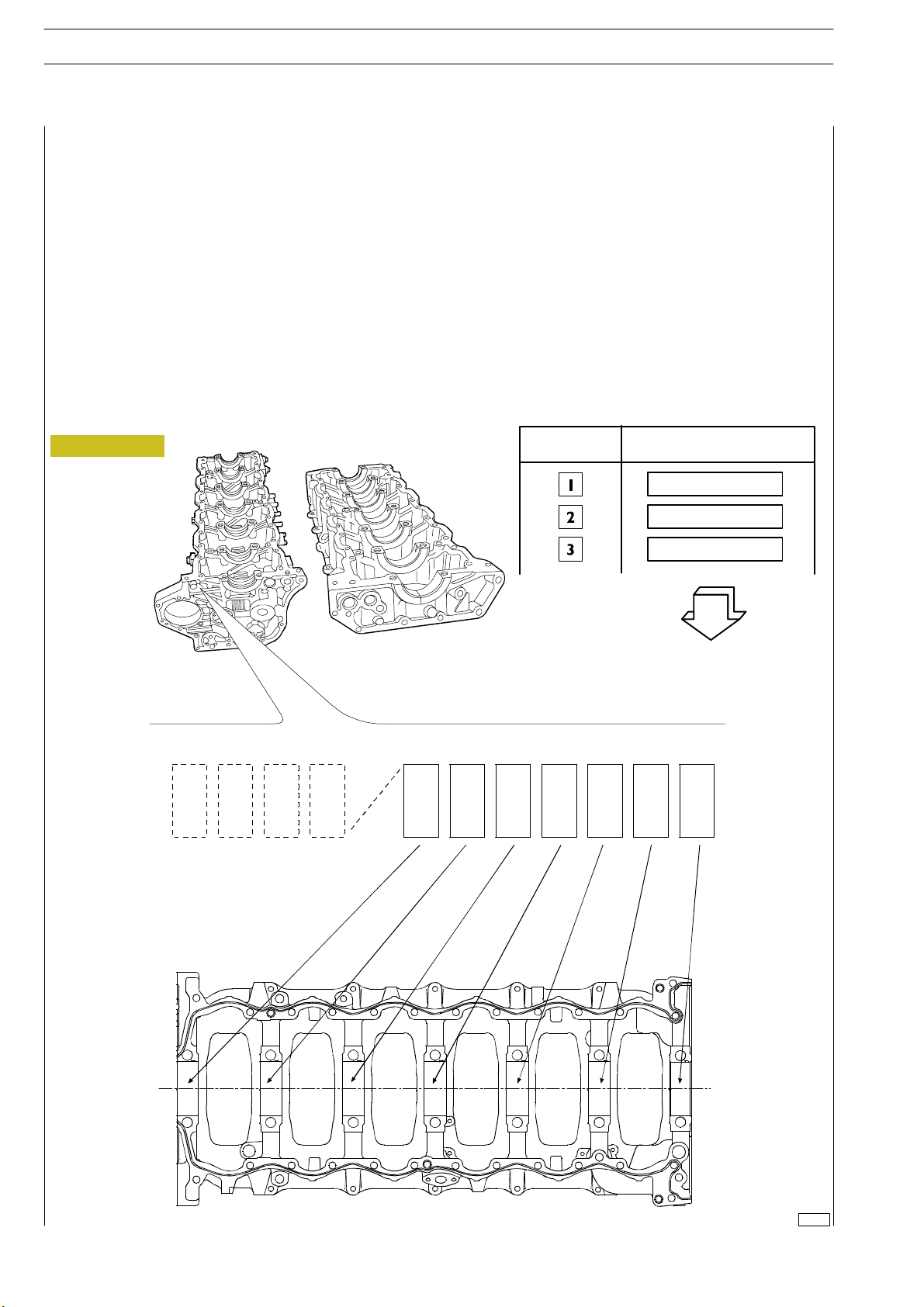
52
ENGINE F2B
S
TRALIS AT/AD
PRELIMINARY MEASUREMENT OF MAIN AND BIG END BEARING SHELL SELECTION DATA
For each of the journals of the crankshaft, it is necessary to carry out the following operations:
MAIN JOURNALS:
- Determine the c lass of diameter o f the seat in the
crankcase.
- Determine t he class of diameter of the main journal.
- Select the class of th e bearing shells to mount.
CRANKPINS:
- Determine the c lass of diameter o f the seat in the
connecting rod.
- Determine the class of diameter of the crankpin.
- Select the class of th e bearing shells to mount.
DEFINING THE CLASS OF DIAMETER OF THE SEATS FOR BEARING SHELLS ON THE CRANKCASE
On the front of the crankcase, two sets of numbers are marked in the position shown (Figure 67 at to p).
- The first set of digits (four) is the coupling number of the crankcase with its base.
- The following seven digits, taken singly, are the class of diameter of each of the seats referred to (Figure 67 at bottom).
- Each of these digits may be 1, 2 or 3.
Figure 67
CLASS
MAIN BEARING HOUSING
NOMINAL DIAMETER
89.000 to 89.009
89.010 to 89.019
89.020 to 89.030
47535
Base - January 2003 Print 603.93.141
Page 78
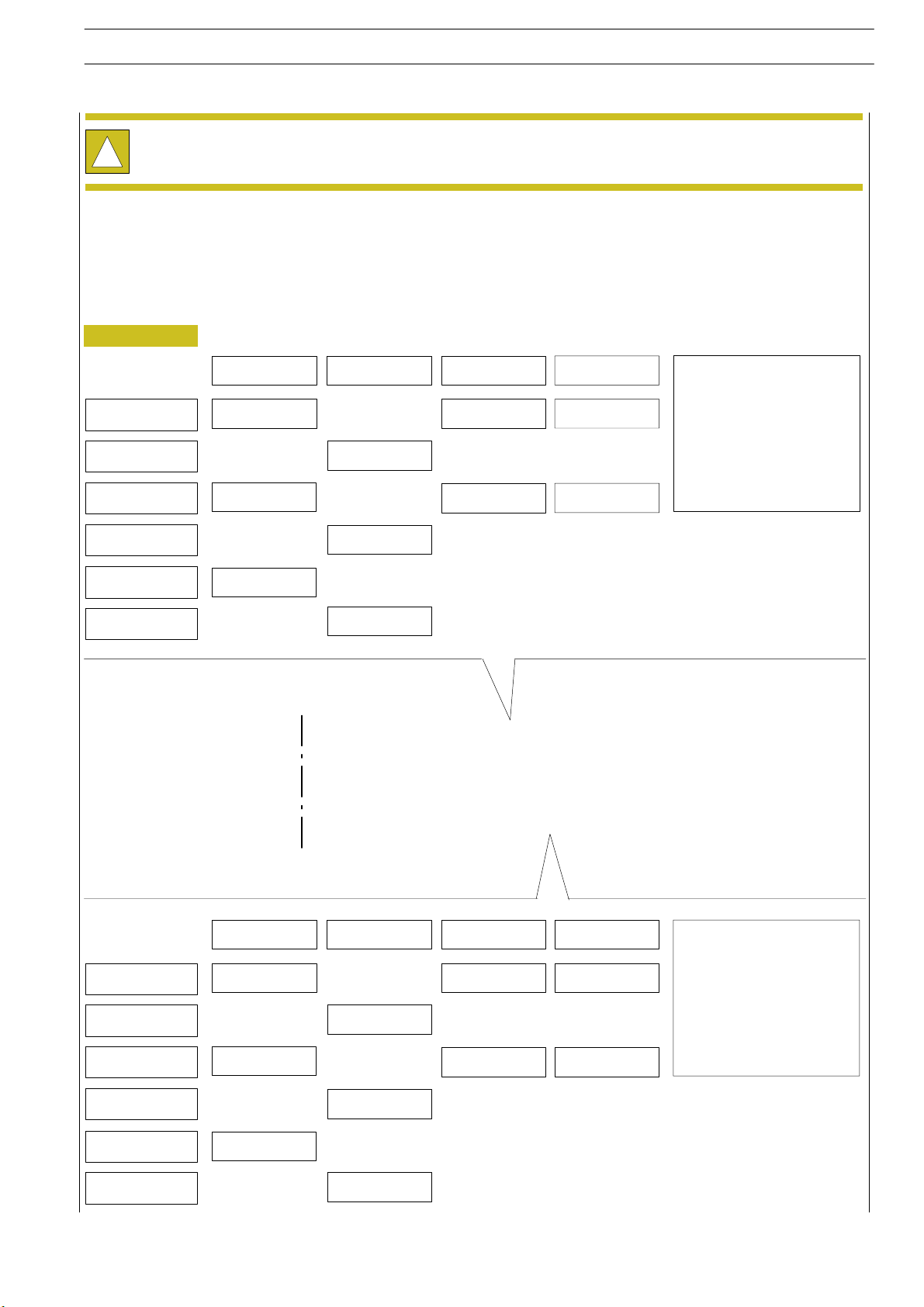
STRALIS AT/AD
ENGINE F2B
Selecting the main and big end bearing shells
To obtain the required assembly clearances, the main and big end bearing shells need to be selected as described
!
hereunder.
This operation makes it possible to identify the most suitable bearing shells for each of the journals (the bearingshells, if necessary,
can have different classes from one journal to another).
Depending on the thickness, the bearing shells are selected
in classes of tolerance marked by a coloured sign (red-green
— red/black — green/black).
Figure 68
The following tables give the specifications of the main and
big end bearing shells available as spares in the standard sizes
(STD) and in the permissible oversizes (+0.127, +0.254,
+0.508).
53
red
red/black
green
green/black
yellow*
yellow/black*
STD
2.000 to 2.010
2.011 to 2.020
2.021 to 2.030
+0.127
2.063 to 2.073
2.074 to 2.083
2.084 to 2.093
+0.254
2.127 to 2.137
2.138 to 2.147
+0.508
2.254 to 2.264
2.265 to 2.274
STD
red
3.000 to 3.010
red/black
green
3.011 to 3.020
green/black
yellow*
3.021 to 3.030
yellow/black*
Print 603.93.141 Base - January 2003
+0.127
3.063 to 3.073
3.074 to 3.083
3.084 to 3.093
+0.254
3.127 to 3.137
* Fitted in production only and not supplied as spares
+0.508
2.254 to 3.264
Page 79
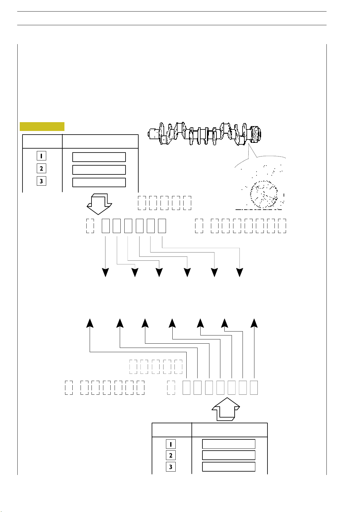
54
ENGINE F2B
S
TRALIS AT/AD
DEFINING THE CLASS OF DIAMETER OF THE MAIN JOURNALS AND CRANKPINS (Journals with nominal diameter)
Main journals and crankpins: determining the class of diameter of the journals.
Three sets of numbers are marked on the crankshaft in the position shown by the arrow (Figure 69 at top):
- The first number, of five digits, is the part number of the shaft.
- Under this number, on the left, a set of six digits refers to the crankpins and is preceded by a single digit showing the status
of the journals (1 = STD, 2 = -0.127), the other six digits, taken singly, give the class of diameter of each of the cran k pins
they refer to (Figure 69 at top).
- The set of seven digits, on the right, refers to the main jou rn als and is preceded by a single digit: the single digit shows the
status of the journals (1 = STD, 2 = -0.127), the other seven digits, taken singly, give the class of diameter of each of the
main journals they refer to (Figure 69 at bottom).
Figure 69
CLASS
CRANKPIN
NOMINAL DIAMETER
72.915 to 72.924
72.925 to 72.934
72.935 to 72.945
CLASS
MAIN JOURNALS
NOMINAL DIAMETER
82.910 to 82.919
82.920 to 82.929
82.930 to 82.940
Base - January 2003 Print 603.93.141
Page 80
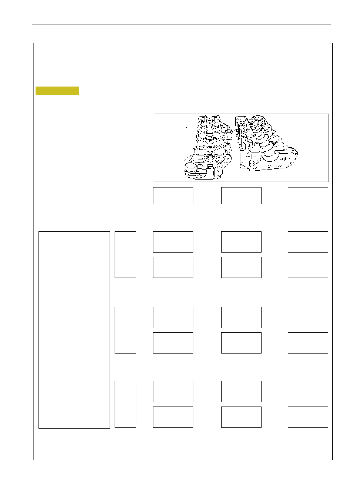
STRALIS AT/AD
Selection of main half-bearings (nominal diameter pins)
After detecting, for each journal, the necessary data on block and crankshaft, select the type of half-bearings to be used, in
compliance w ith the following table:
Figure 70
ENGINE F2B
STD.
55
1
2
1 2 3
green
green
red
red
green
green
green
green
green
green
green
green
red
red
red
3
red
Print 603.93.141 Base - January 2003
red
red
Page 81
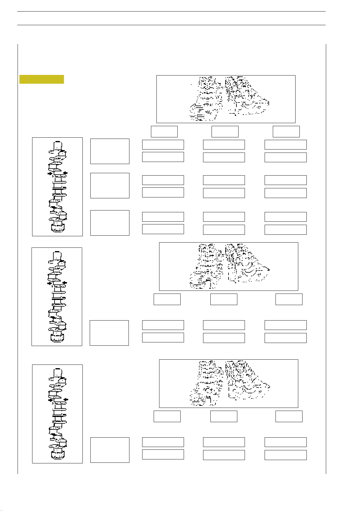
56
ENGINE F2B
Selection of main half-bearings (rectified pins)
If the journals have been rectified, the procedure described cannot be applied.
In this case, make sure that the new diameter of the journals is as specified on the t able and install the only half-bearing type
required for this undersizing.
Figure 71
S
TRALIS AT/AD
red/black =
mm 3.063 to 3.073
green/black =
mm 3.063 to 3.073
-0.127
82.784
82.793
82.794
82.803
82.804
82.814
-0.254
1
2
3
1 2 3
green/black
green/black
red/black
red/black
red/black
red/black
green/black
green/black
green/black green/black
green/black
red/black
red/black
green/black
green/black
green/black
red/black
red/black
red =
mm 3.127 to 3.137
82,666
82,686
-0.508
red =
mm 3.254 to 3.264
82.412
82.432
1 2 3
red red red
red red red
1 2 3
red red red
red red red
Base - January 2003 Print 603.93.141
Page 82
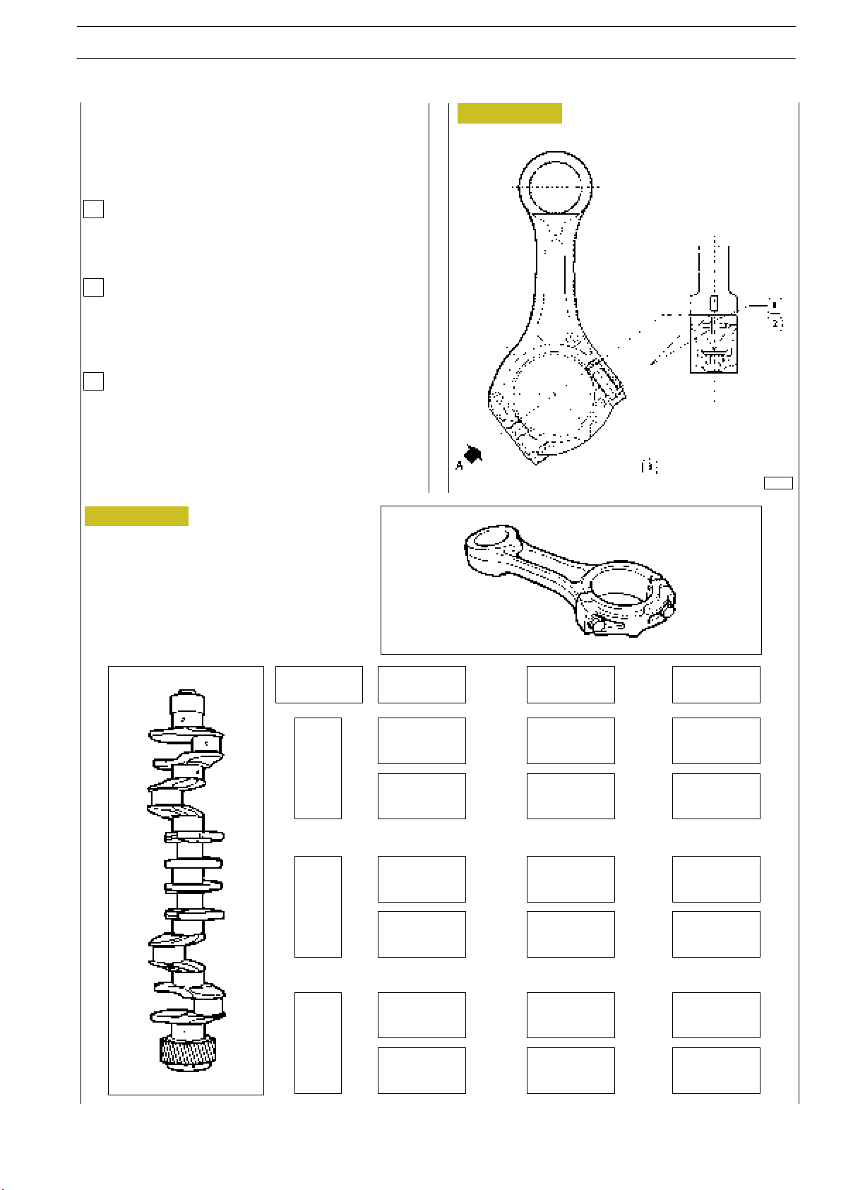
STRALIS AT/AD
ENGINE F2B
57
SELECTINGTHEBIGENDBEARINGSHELLS
(JOURNALS WITH NOMINAL DIAMETER)
There are three markings on the body of the connecting rod
in the position shown in the view from ”A”:
1
Letter indicating the class of weight:
A = 2890 to 2920 g.
B = 2921 to 2950 g.
C = 2951 to 2980 g.
Number indicating the selection of the diameter of the
2
big end bearing seat:
1 = 77.000 to 77.010 mm
2 = 77.011 to 77.020 mm
3 = 77.021 to 77.030 mm
Numbers identifying the cap-connecting rod coupling.
3
The number, indicating the class of diameter of the bearing
shell seat may be 1, 2 o 3.
Determine the type of big end bearing to fit on each journ al
by following the indications in the table (Figure 73).
Figure 73
Figure 72
VIEW FROM “A”
47557
STD.
Class
1
2
1 2 3
green
green
red
red
green green
green green
green
green green
green
red
red
red
3
red
Print 603.93.141 Base - January 2003
red
red
Page 83
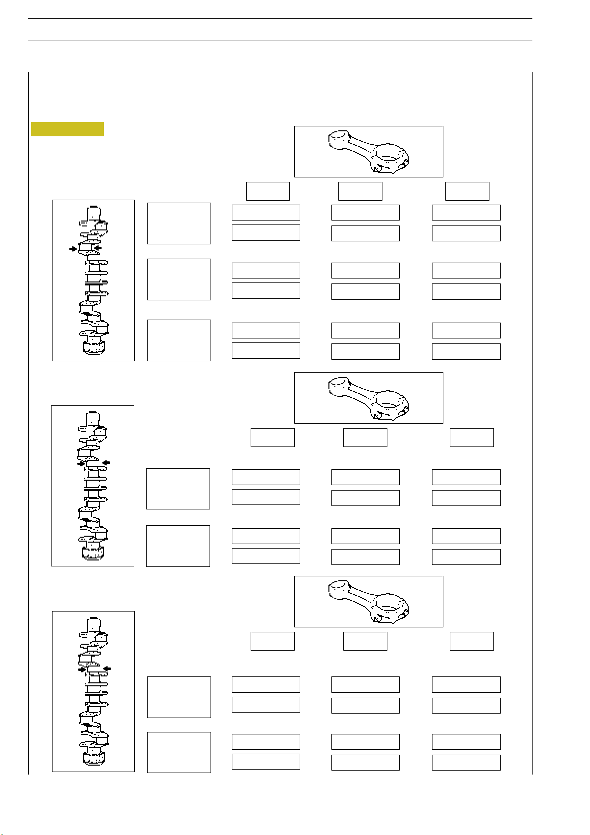
58
ENGINE F2B
Selection of connecting rod half-bearings (rectified pins)
If pins have been rectified, the procedure described must be applied.
In this case, (for each undersizing) determine the tolerance field the new big end pins belong to, and install the half-bearings
identified acco rding to the relative table.
Figure 74
red/black =
mm 2.074 to 2.083
green/black =
mm 2.063 to 2.073
-0.127
S
TRALIS AT/AD
1 2 3
72.789
72.798
72.799
72.808
72.809
72.818
-0.254
red
mm 2.127 to 2.137
green =
mm 2.138 to 2.147
72.671
72.680
1
2
3
green/black
green/black
red/black
red/black
red/black
red/black
green/black
green/black
green/black green/black
green/black
red/black
red/black
1 2 3
red green green
red green green
green/black
green/black
green/black
green/black
green/black
72.681
72.691
red red green
red red green
-0.508
red =
mm 2.254 to 2.264
green =
mm 2.265 to 2.274
72.417
72.426
72.427
72.437
Base - January 2003 Print 603.93.141
1 2 3
red green green
red green green
red red green
red red green
Page 84
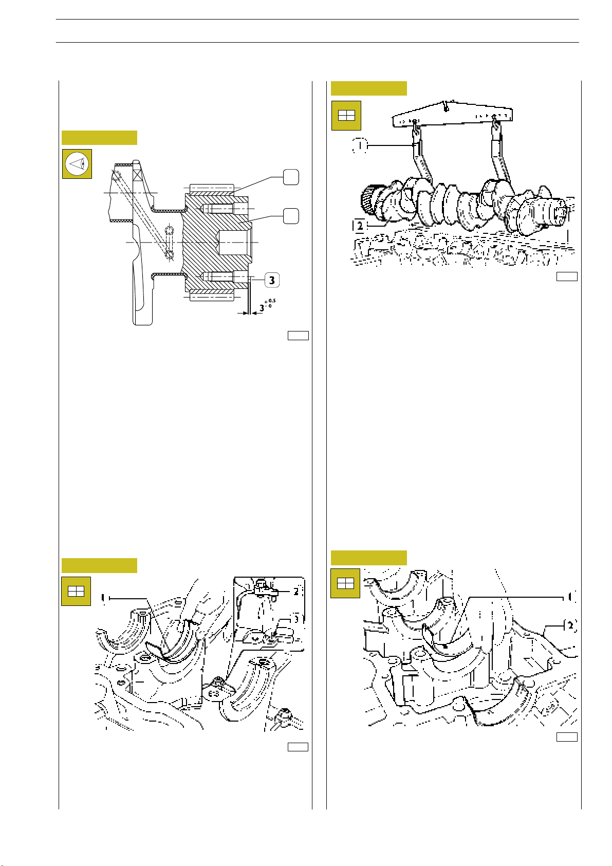
STRALIS AT/AD
540815 Replacing the timing control gear and
the oil pump
Check that the teeth of the gears are not damaged or worn,
otherwise remove them using the appropriate extractor.
Figure 75
1
2
49020
After fitting the gear (1) on the crankshaft (2), heat it for
~15 minutes in an oven at temperature not higher than
180°C.
Let them cool down after the in stallation .
If changing the pin (3), after fitting it on, check it protrudes
from the crankshaft as shown in the figure.
ENGINE F2B
Figure 77
47578
Using the hoist and hook 99360500 (1) mount the driving
shaft (2).
59
540811 Checking main journal installation
clearance
Figure 76
47579
Install the oil spray nozzles (2) and have the dowel coincide
with the block hole (3).
Install the half-bearings (1) on the main bearings.
Figure 78
49021
Install the half-bearings (1) on the main bearings in the
underblock (2).
Check the installation clearance between the main journals
and the relative bearings as follows:
Print 603.93.141 Base - January 2003
Page 85
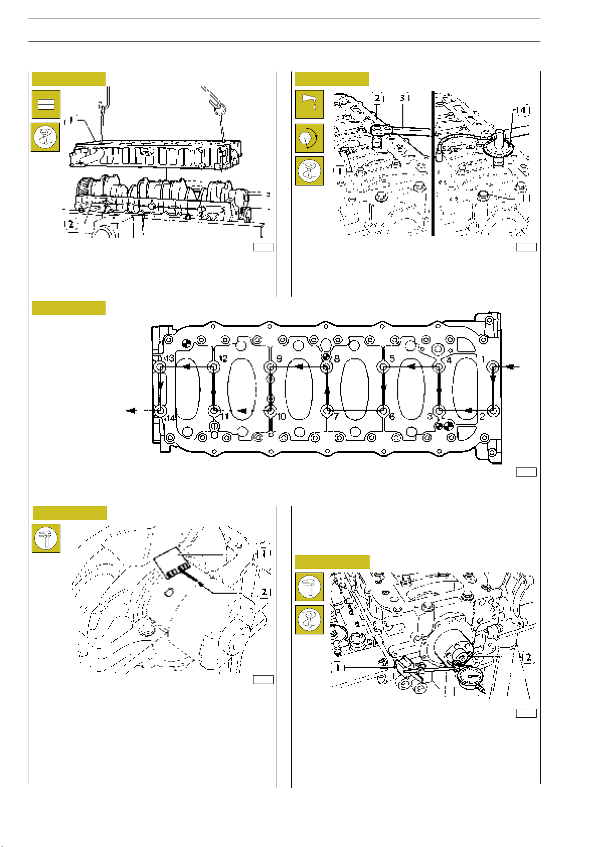
60
ENGINE F2B
Figure 79 Figure 80
S
TRALIS AT/AD
α
49022
Place a piece of calibrated wire on the journal of the
crankshaft (2), parallel to the longitudinal axis; install the
underblock (1), by hoist and appropriate hooks.
Figure 81
FRONT SIDE
Diagram showing the tightening order of the screws fixing the lower under-block to the block
Figure 82
47578
- Lubricate inside screws (1) con UTDM oil, and tigh t en
them by dynamometric wrench to 140 Nm torque,thus
with 60º angle closing, following the diagram in Figure 81.
44898
Checking crankshaft end float
Figure 83
- Remove the under-block
47579
The clearance between the main bearings an d the journals
is obtained by comparing the calibrated wire length (2) at the
47588
maximum deflection point, with the calibrated sc ale on the
coating (1) cont ain ing the calibrated wire (1).
Numbers shown on the scale specify the clearance in
coupling millimeters. If the clearance obtained is different
from the clearance required, replace the half-bearings and
repeat this check.
Base - January 2003 Print 603.93.141
End float is checked by placing a magnetic dial gauge (1) on
the crankshaft (2),as shown in the figure. If the value obtained
is higher than specified, replace the rear thrust half-bearings
and repeat this check.
Page 86
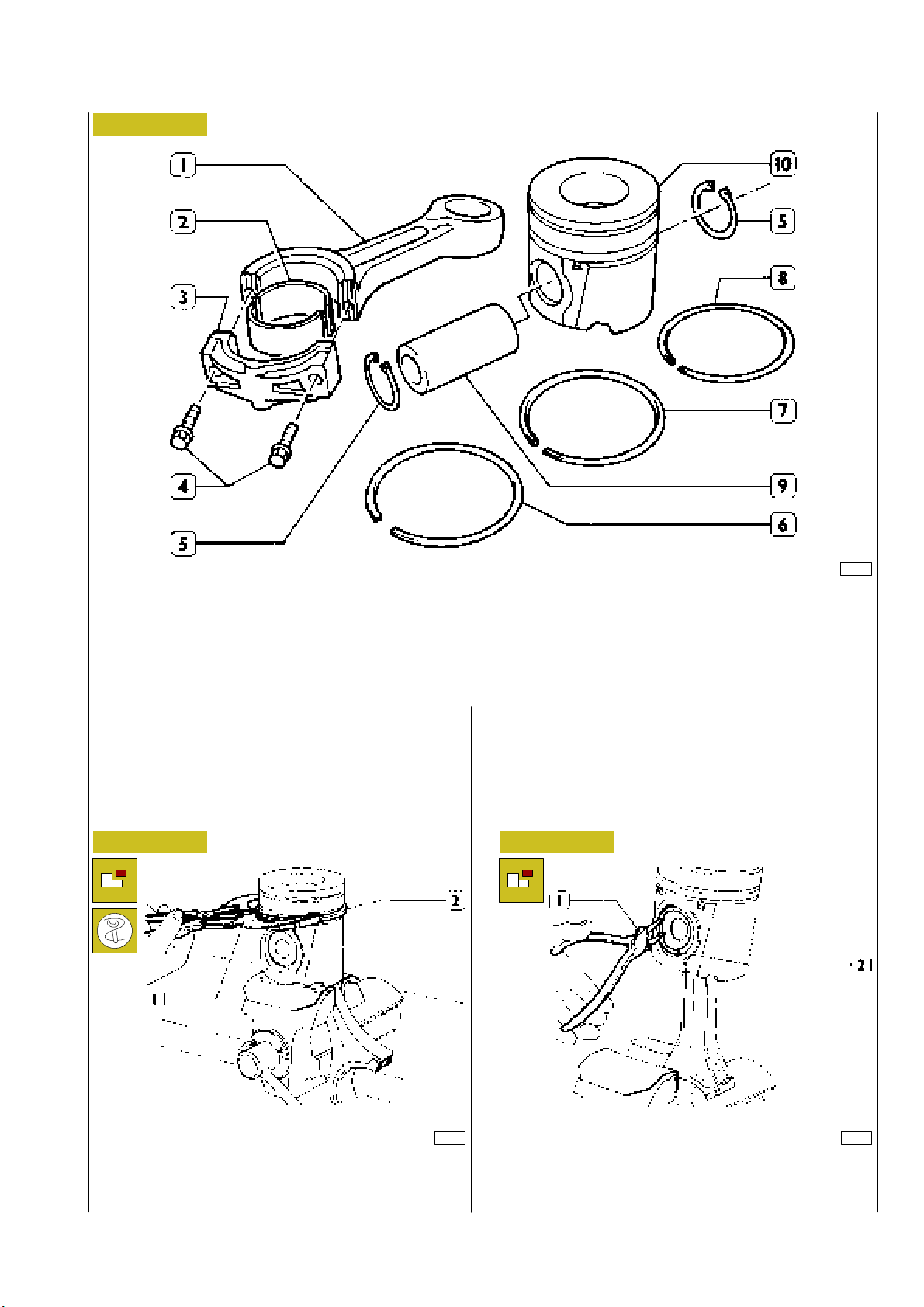
STRALIS AT/AD
5408 PISTON-CONNECTING ROD ASSEMBLY
Figure 84
ENGINE F2B
61
47580
PISTON CONNECTING ROD ASSEMBLY
1. Connecting rod body - 2. Half bearings - 3. Connecting rod cap - 4. Cap fastening screws - 5. Split ring - 6. Scraper ring with
spiral spring - 7. Bevel cut sealing ring - 8. Trapezoidal sealing ring - 9. Piston pin - 10. Piston
Make sure the piston does show any trace of seizing, scoring,
cracking; replace as necessary.
Pistons are equipped with three elastic rings: a sealing ring, a
trapezoidalringandascraperring.
Pistons are grouped into classes A and B for diameter.
Removal
Figure 85
Figure 86
49023
Removal of the piston split rings (2) u s ing the pliers 99360184
(1).
Print 603.93.141 Base - January 2003
Remove the piston pin split rings (2) usin g the round tipped
pliers (1).
49024
Page 87
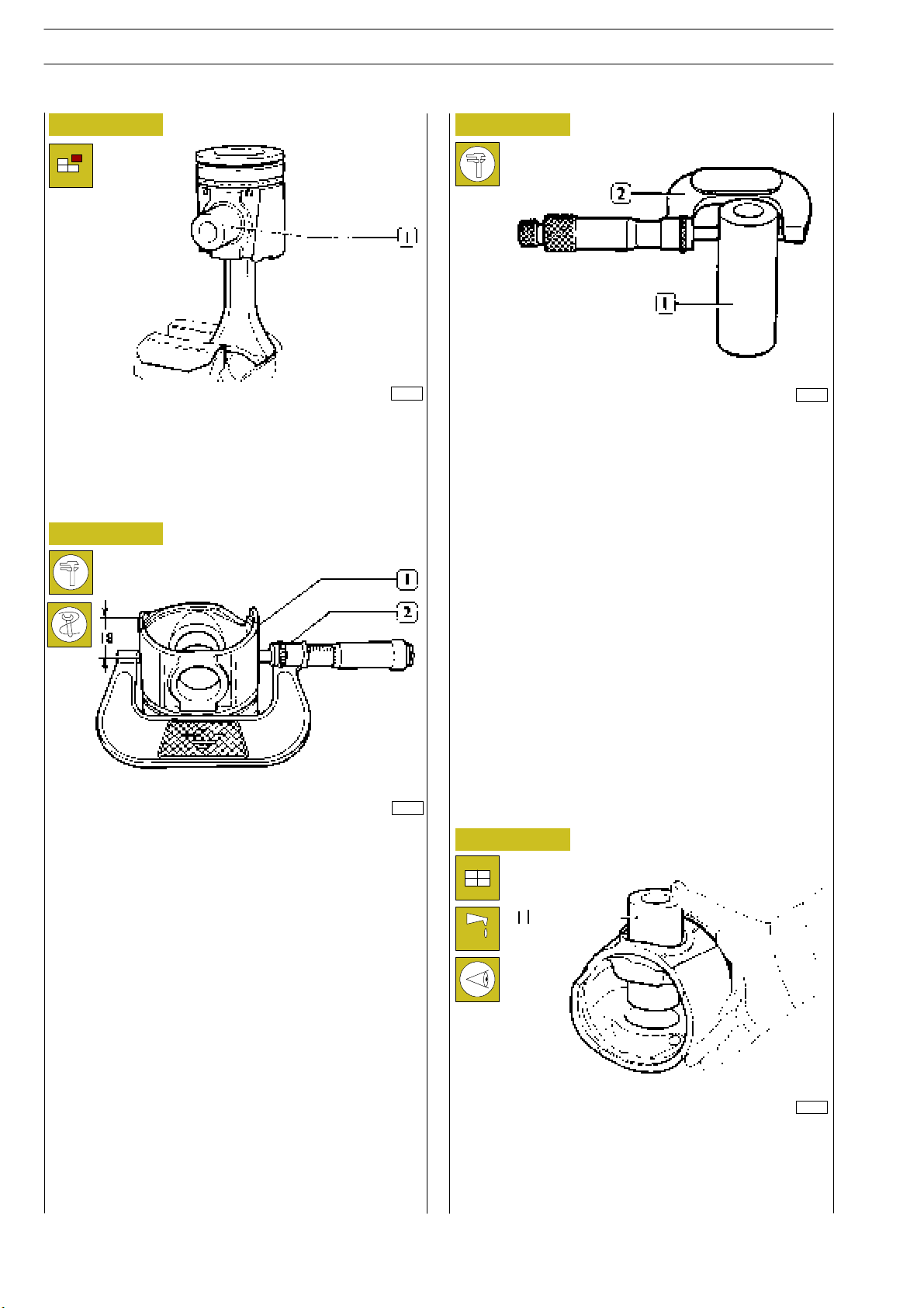
62
ENGINE F2B
S
TRALIS AT/AD
Figure 87
Remove the piston pin (1).
If removal is difficult use the appropriate beater.
Measuring the diameter of the pistons
Figure 88
49025
Figure 89
32618
Measuring the gudgeon pin diameter (1) with a micrometer
(2).
47584
Using a micrometer (2), measure the diameter of the piston
(1) to determine the assembly clearance; the diameter should
be measured at the specified value.
Conditions for correct gudgeon pin-piston coupling
Figure 90
49026
Lubricate the pin (1) and the relevant housing on the piston
hubs with engin e oil; piston must be inserted with a slight
finger pressure and it should not come out by gravity.
Base - January 2003 Print 603.93.141
Page 88
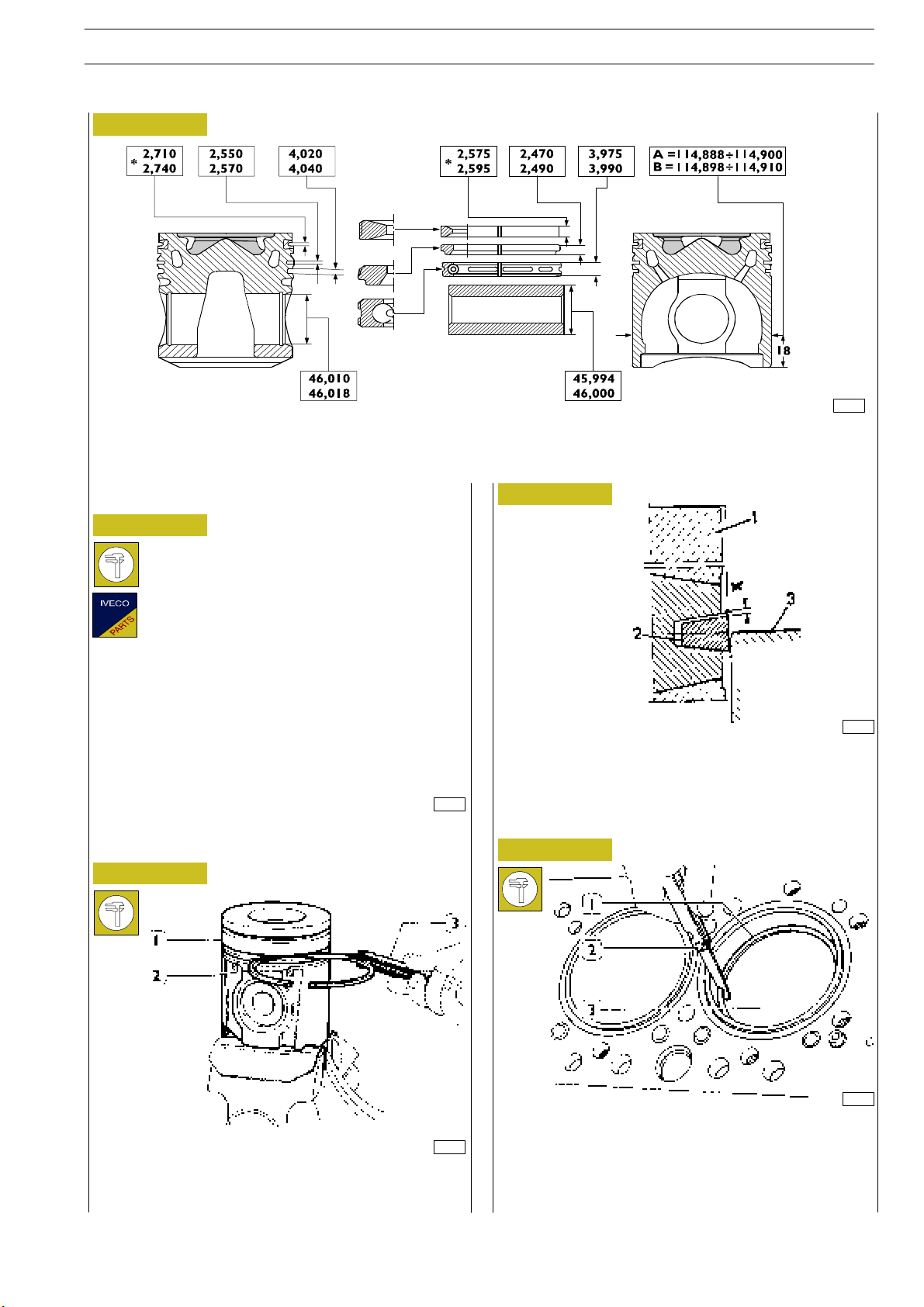
STRALIS AT/AD
Figure 91
ENGINE F2B
63
Drawing No. 500388370
MAIN DATA ON PISTONS, AND PISTONS RINGS
* Values are determined on ∅ of 112 mm.
540842 Piston rings
Figure 92
16552
Check the thickness of the piston ring (2) using a micrometer
(1).
Figure 93
77816
Figure 94
3513
The sealing ring (2) of the 1º cavity is trapezoidal. Clearance
“X” between the sealing ring and its housing is measured by
placing the piston (1) with its ring in the cylinder barrel (3),
so that the sealing ring is half-projected out of the cylinder
barrel.
Figure 95
36134
Check the opening between the ends of the sealing rings (1),
16552
Check the clearance between the sealing rings (2) and the
using a thickn ess gauge (2), entered i n the cylinder barrel (3).
If the distance betweenends is lower or higher than the value
required, replace split rings.
relative piston housin gs (1) using a thikness gauge (3).
Print 603.93.141 Base - January 2003
Page 89
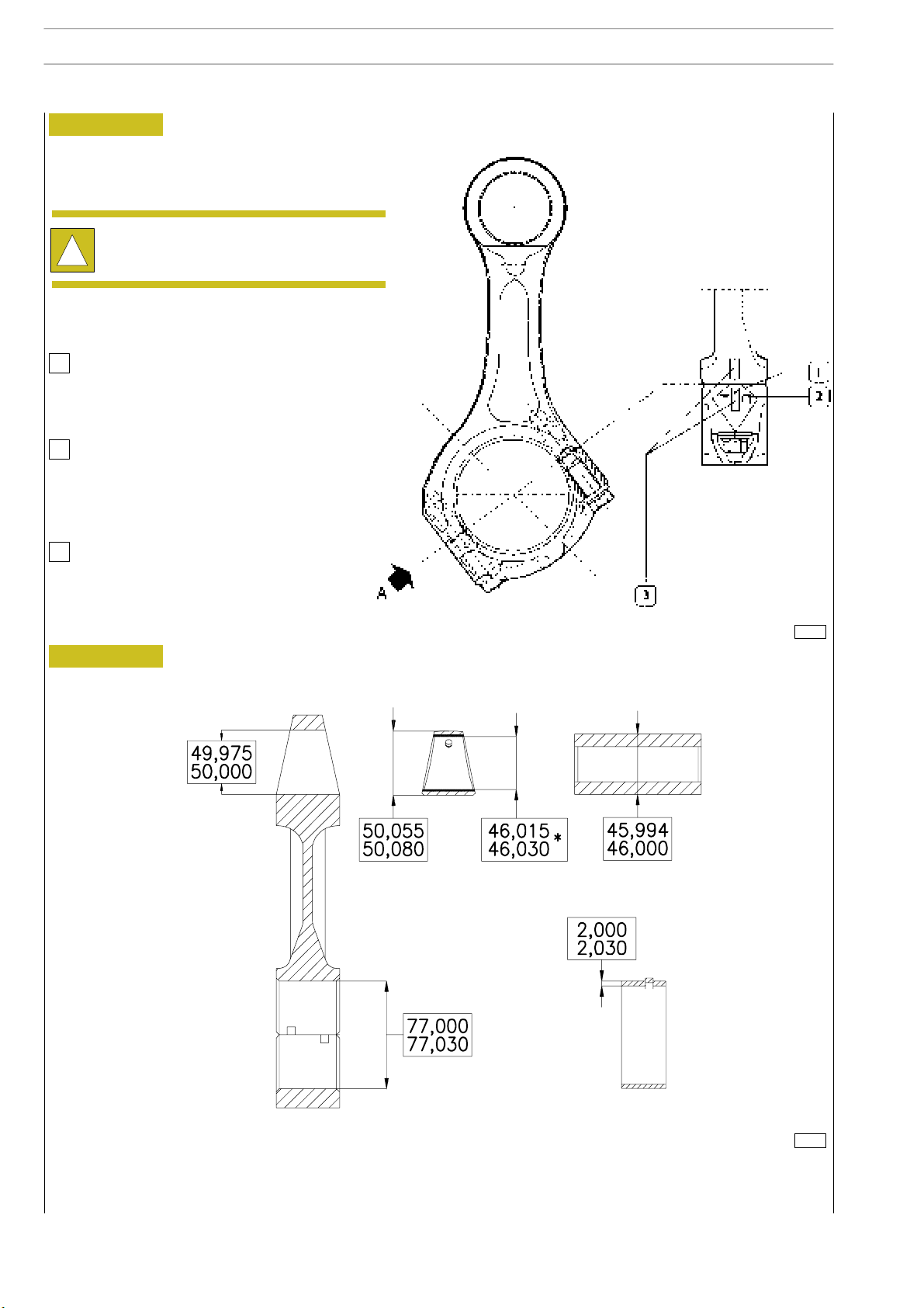
64
ENGINE F2B
540830 CONNECTING ROD
Figure 96
Data concerning the class section of connecting rod
housing and weight are stamped on the big end.
When installing connecting rods, make su re
they all belong to the same weight class.
!
DIAGRAM CONNECTING ROD MARKS
Letter indicating the weight class:
1
A = 2890 to 2920 g.
B = 2921 to 2950 g.
C = 2951 to 2980 g.
Number indicating the selection of diameter for
2
the big end bearing housing:
1 = 77.000 to 77.010 mm
2 = 77.011 to 77.020 mm
3 = 77.021 to 77.030 mm
Numbers identifying cap-connecting rod coupling
3
S
TRALIS AT/AD
VIEW FROM “A”
Figure 97
47557
44927
MAIN DATA - BUSH, CONNECTING ROD, PIN AND HALF-BEARINGS
* Values to be obtained after installing the bush
Base - January 2003 Print 603.93.141
Page 90
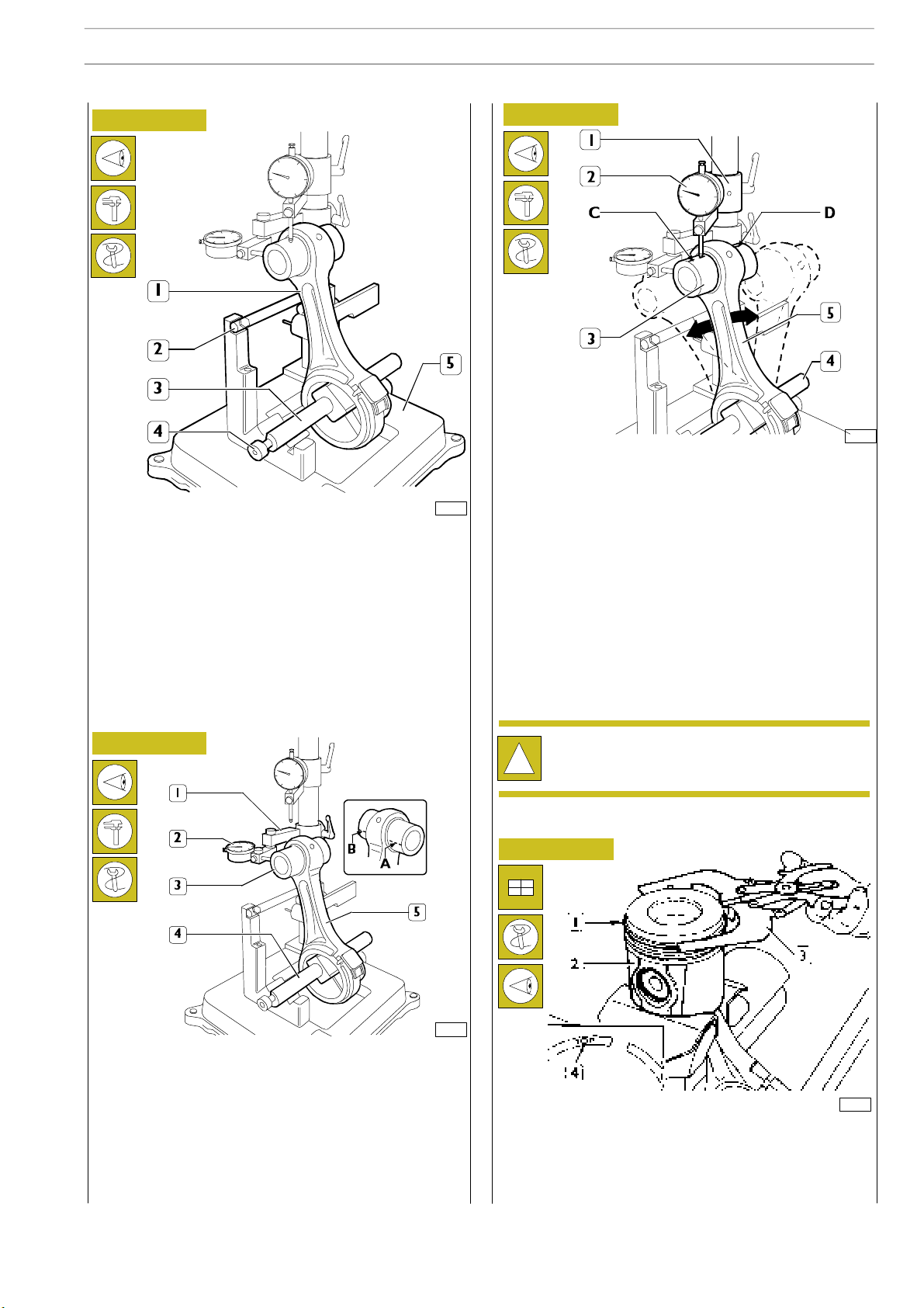
STRALIS AT/AD
ENGINE F2B
65
Checking connecting rod alignment
Figure 98
61696
Checking axis alignment
Check the alignment of the axes of the connecting rods (1)
with device 99395363 (5), proceeding as follows:
- Fit the connecting rod (1) on the spindle of the tool
99395363 (5) and lock it with the screw (4).
- Set the spindle (3) on the V-prisms, resting th e connecting
rod (1) on the stop bar (2).
Checking torsion
Checking bending
Figure 100
61695
Check the bending of the connecting rod (5) by comparing
two points C and D of the pin (3) on the vertical plane of the
axis of the connecting rod.
Positionthe verticalmount (1) of the dial gauge (2) so that this
restsonthepin(3)atpointC.
Swing the connecting rod backwardsand forwardsseekingthe
highest position of the pin and in this condition zero the dial
gauge (2).
Shift the spindle (4) with the connecting rod (5) and repeat
the check on the highest point on the opposite side D of the
pin (3). The difference between point C and point D must be
no greater than 0.08 mm.
Mounting the connecting rod - piston assembly
Carry out the steps for removal described on page 61 in
reverse order.
Figure 99
61694
Check the torsion of the connecting rod (5) by comparing
two points (A and B) of the pin (3) on the horizontal plane
of the axis of the connecting rod.
Position the mount (1) of the dial gauge (2) so that this
pre-loads by approx. 0.5 mm on the pin (3) at point A and
zero the dial gauge (2). Shift the spindle (4) wi th the
connecting rod (5) and compare any deviation on the
opposite side B of the pin (3): the difference between A and
B must be no greater than 0.08 mm.
The connecting rod screws can be reused as long as
the diameter of the thread is not less than 13.4 mm.
!
Mounting the piston rings
Figure 101
49029
To fit the piston rings (1) on the piston (2) use the pliers
99360184 (3).
The rings need to be mounted with the word ”TOP” (4)
facing upwards. Direct the ring openings so they are
staggered 120° apart.
Print 603.93.141 Base - January 2003
Page 91
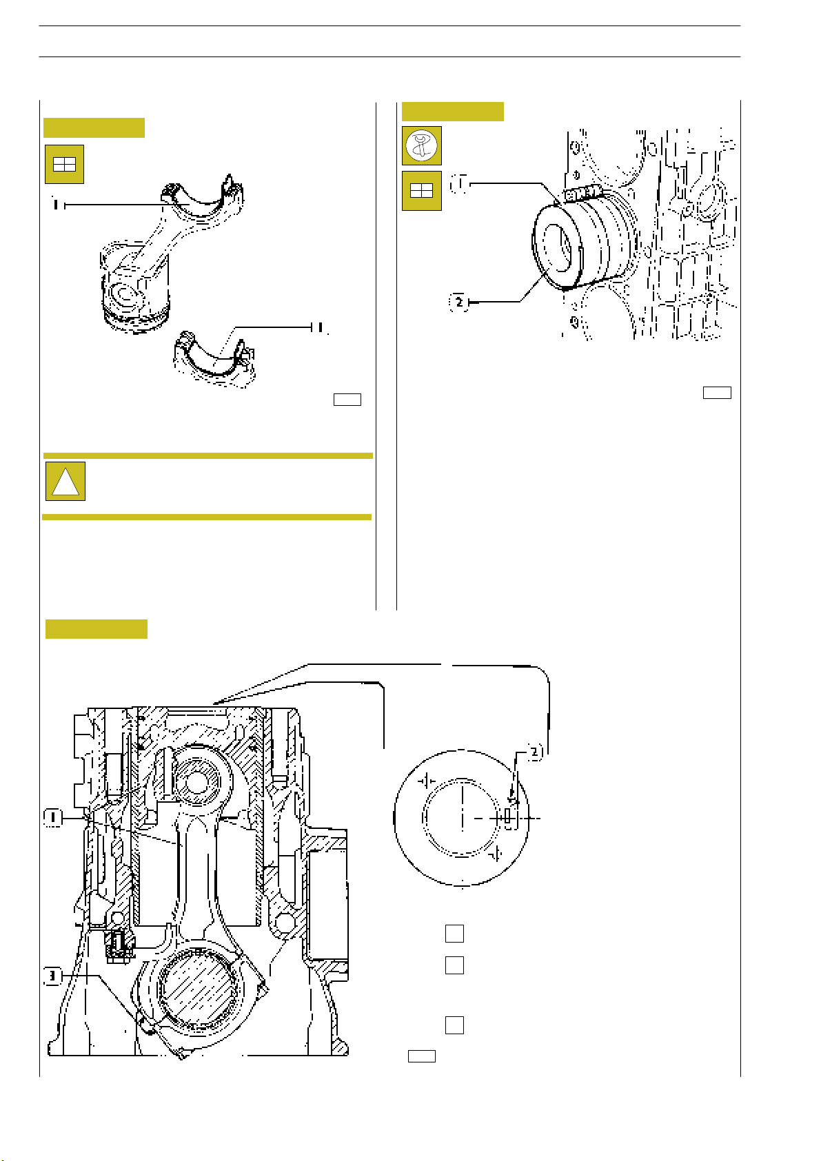
66
ENGINE F2B
Fitting the connecting rod-piston assembly into the piston liners
Figure 102
Figure 104
S
TRALIS AT/AD
49030
Install half-bearings (1), selected as specified on page 66, on
both the connecting rod and the cap.
As spares, class A pistons are provided and can be
!
fitted also to cylinder barrels belonging to class B.
Fit the connecting rod-piston assemblies (1) into the piston
liners (2) using band 99360605 (1, Figure 104). Check the
following:
- the openings of the split rings are offset by 120°;
Figure 103
47593
- all pistons belong to the same class, A or B;
- ideogram stamped on the piston crown is placed toward
the engine flywheel, or the cavity, on the piston cover,
corresponds to the position of the oil spray nozzles.
Piston protrusion check
Once assembly is complete, check piston protrusion from
cylinder barrels: it must be 0.32-0.69 mm.
Connecting rod-piston assembly
1
Marking area on the piston crown of ideogram
2
specifying the assembly position and t h e
selection class
Connectingrodmarkingarea(seefig.96).
3
61831
Base - January 2003 Print 603.93.141
Page 92
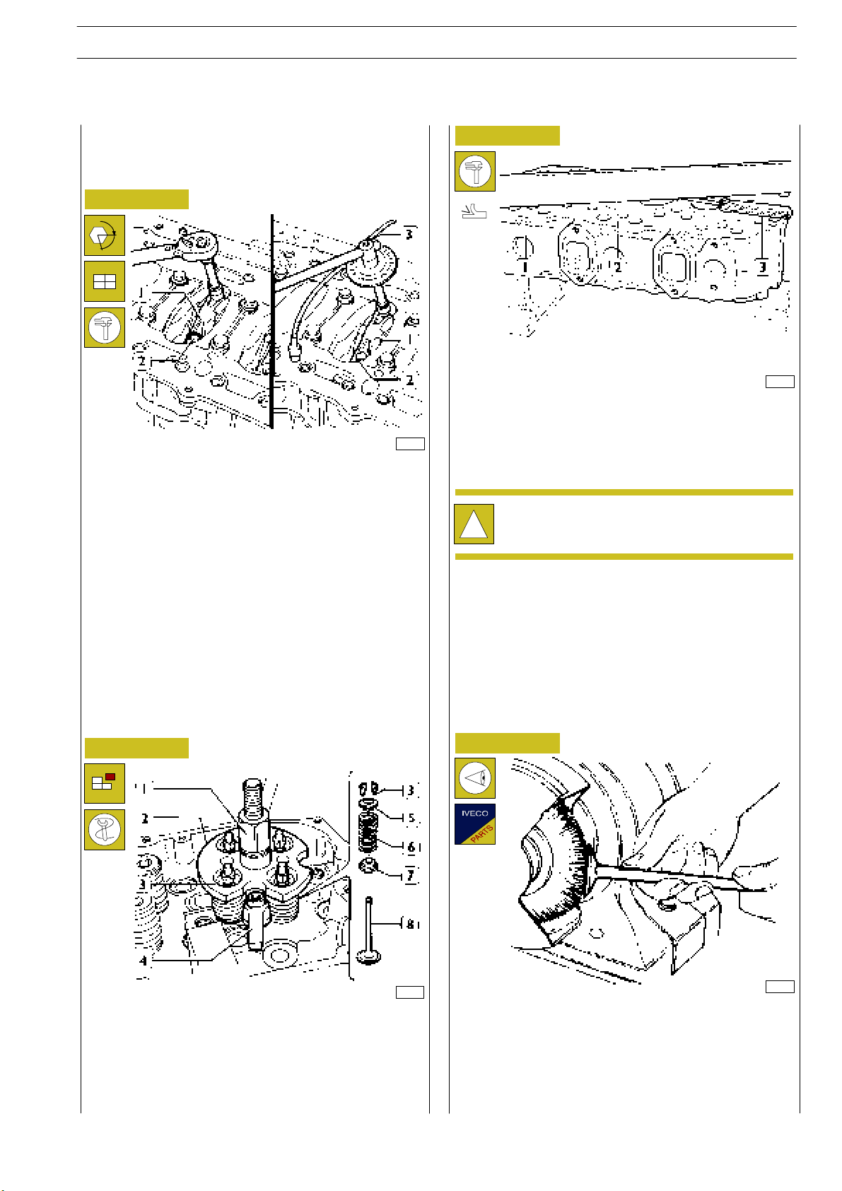
STRALIS AT/AD
ENGINE F2B
67
540831 Checking assembly clearance of big
end pins
To check the clearance proceed as follows:
Connect the connecting rods to the relative main journals,
place a length of calibrated wire on the latter.
Figure 105
α
47594
Install the connecting rod caps (1) wit h half-bearings; tighten
the con n ec t ing rod cap fixing screws (2) to 50 Nm (5 kgm)
torque. By tool 99395216 (3), tighten the screws further at
40° angle.
Remove the caps and check the clearance by comparing the
width of the calibrated wire with the scale calibration on the
envelope containing the wire.
Checking the planarity of the head on the cylinder block
Figure 107
The planarity (1) is checked using a ruler (2) and a thikness
gauge (3). If deformations exist, surface the head usin g
proper surface grinder; the maximum amount of material to
be removed is 0.2 mm.
After leveling, make sure that valve sinking and
injector protrusion are as described in the relative
!
paragraph.
(Demonstration)
36159
540610 CYLINDER HEAD
Before taking down the cylinder head, check the seal using
the appropriate tool; in case of leakage replace the cylinder
head.
Valve removal
Figure 106
47583
Install and fix too l 99360264 (2) with bracket (4); tighten by
lever (1) until cotters are removed (3); remove the tool (2)
and the upper plate (5), the spring (6) and the lower plate (7).
Repeat the operation on all the valves. Turn the cylinder head
upside down and remove the valves (8).
540622 VALVE
Removing deposits and checking the valves
Figure 108
48625
Remove carbon deposits using the metal brush supplied.
Check that the valves show no signs of seizure or cracking.
Check the diameter of the valve stem using a micrometer
(see fig. 109) and replace if necessary.
Print 603.93.141 Base - January 2003
Page 93
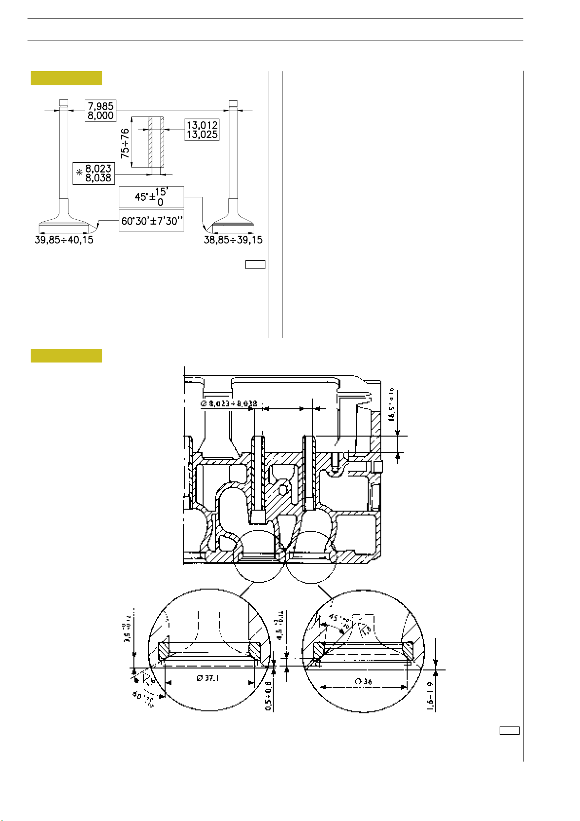
68
ENGINE F2B
S
TRALIS AT/AD
Figure 109
MAIN DATA - VALVES AND VALVE GUIDES
* Values to be obtained after installing the valve guides
540667 VALVE GUIDES
Figure 110
Check, by means of a micrometer, that valve stem diameters
are as specified; if necessary, grind the valves seat w ith a
grinder, removing the minimum quantity of material.
47584
*
INSTALLATION DIAGRAM FOR VALVE GUIDES AND VALVES
47509
* Values to be obtained after installing the guide valves
Base - January 2003 Print 603.93.141
Page 94
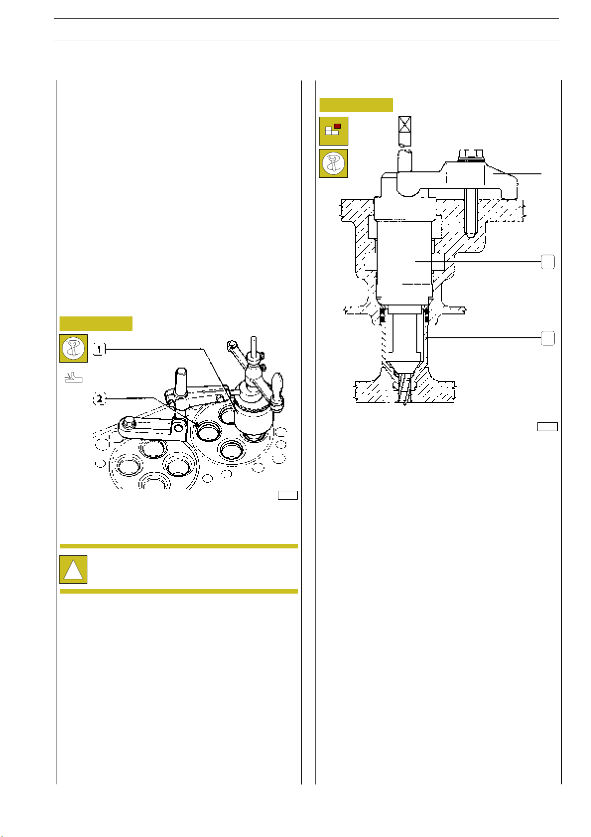
STRALIS AT/AD
Replacing of valve guides
Remove valve guides by means of tool 99360288.
Install by means of tool 99360288 equipped with part
99360294, which determines the exact installation position
of valve gu ides into the cylinder heads; if they are not
available, install the valve guides in the cylinder head so that
they project out by mm 16.3 to 16.7 (fig. 110).
After installing the valve guides, smooth their holes with
sleeker 99390310.
ENGINE F2B
540613 REPLACING INJECTOR HOLDER
CASES
Removal
Figure 112
69
A
Replacing - Reaming the valve seats
To replace the valve seats, remove them using the
appropriate tool.
Figure 111
41032
Ream the valve seats (2) on cylinder head usin g tool
99305019 (1).
1
2
45634
To replace the injector case (2), act as follows:
- thread the case (2) with tool 99390804 (1).
Carry out operation s described in figs. 112-115-116-117
by fixing tools to th e cylinder head by means of braket A.
Valve seats must be reamed whenever val ves or
valve guides are replaced or ground.
!
After reaming the valve seats, use tool 99370415, to make
sure that the valve position, with respect to the cylinder head
surface, is the following:
- -0.5 to -0.8 mm (recessing) of exhaust valves;
- -1.6 to 1.9 mm (recessing) of discharge valves.
Print 603.93.141 Base - January 2003
Page 95
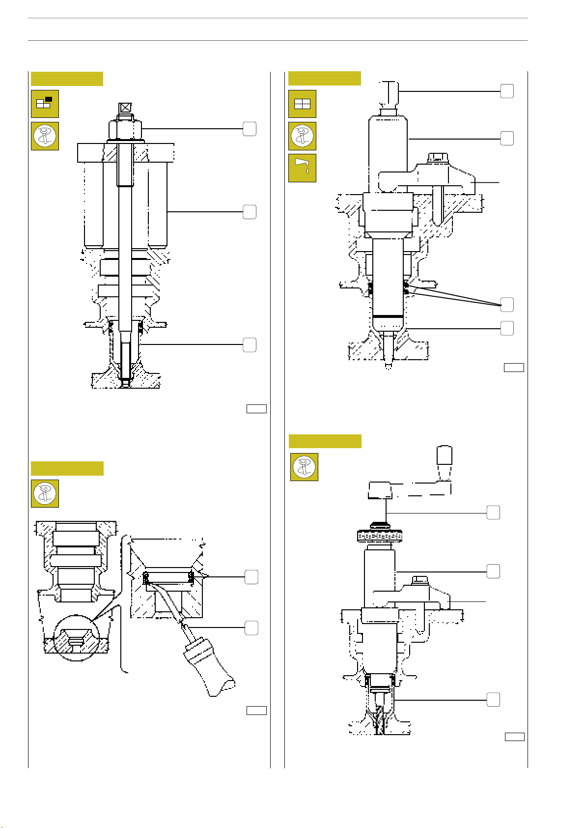
70
ENGINE F2B
S
TRALIS AT/AD
Figure 113
Figure 115
1
1
2
A
2
3
4
3
45631
- fasten extractor 99342149 (2) to case (3), by tightenin g
the nut (1), and pull out the case from cylinder head.
Figure 114
1
2
45635
- Lubricate sealing rings (3) and fit them to the case (4);
fix tool 99360554 (2) to the cylinder head by means of
bracket A, install the new case, tighten the screw (1),
upsetting the case lower part.
Figure 116
1
2
A
45633
- Remove any residue (1), with tool 99390772 (2), from
the cylinder head groove.
45632
- Adjust the casing hole (3) with borer 99394043 (1) and
guide bushing 99394014 (2).
Base - January 2003 Print 603.93.141
3
Page 96
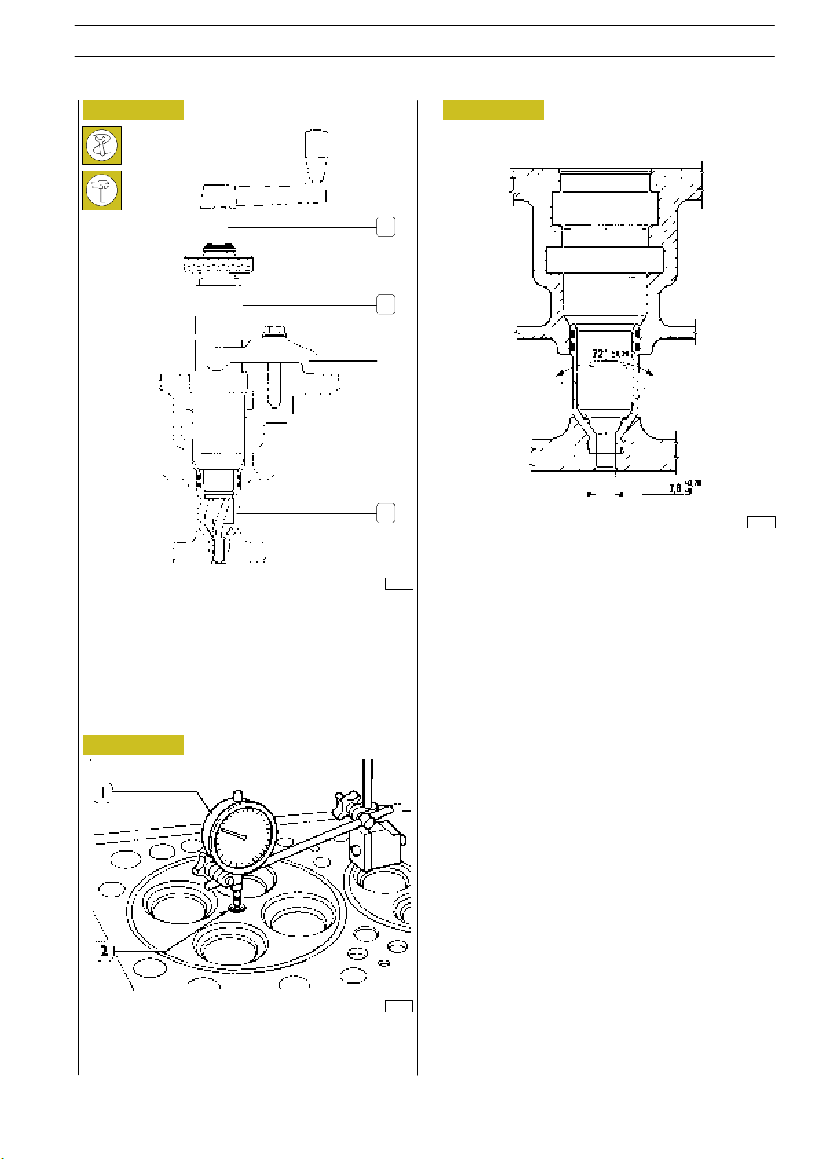
STRALIS AT/AD
ENGINE F2B
71
Figure 117
Figure 119
1
2
A
3
45636
- Through miller 99394041 (1) and bushing 99394014 (2),
ream the injector seat in the case (3), check the injector
protrusion from the cy linder head plane which must be
0.7 mm.
Checking protrusion of injectors
Figure 118
44909
INSTALLATION DIAGRAM FOR
INJECTOR CASE
47585
Using dial gauge (1), ch eck the protrusion of the injector (2)
which must be 0.7 mm.
Print 603.93.141 Base - January 2003
Page 97
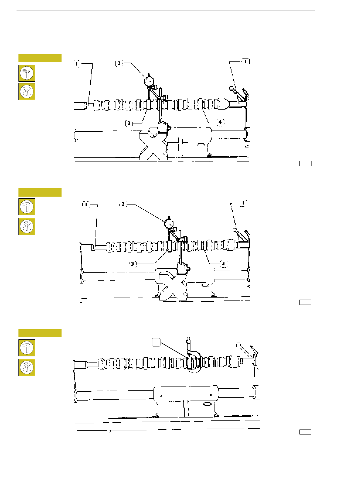
72
ENGINE F2B
S
TRALIS AT/AD
5412 TIMING GEAR
541211 Checking cam lift and pin alignment
Figure 120
47506
Place the camshaft (4) on the tailstock (1) and check cam lift (3) using a centesimal gauge (2); values are shown in table on page
20.
Figure 121
47507
When the camshaft (4) is on the tailstock (1), check alignment of supporting pin (3) using a centesimal gauge (2); it must not exceed
0.030 mm . If misalignment exceeds this value, replace the shaft.
Figure 122
1
47505
In order to check installation clearance, measure bush inner diameter and camshaft pin (1) diameter;the real clearance is obtained
by their difference.
If clearance exceeds 0.150 mm, replace bushes and, if necessary, the camshaft.
Base - January 2003 Print 603.93.141
Page 98
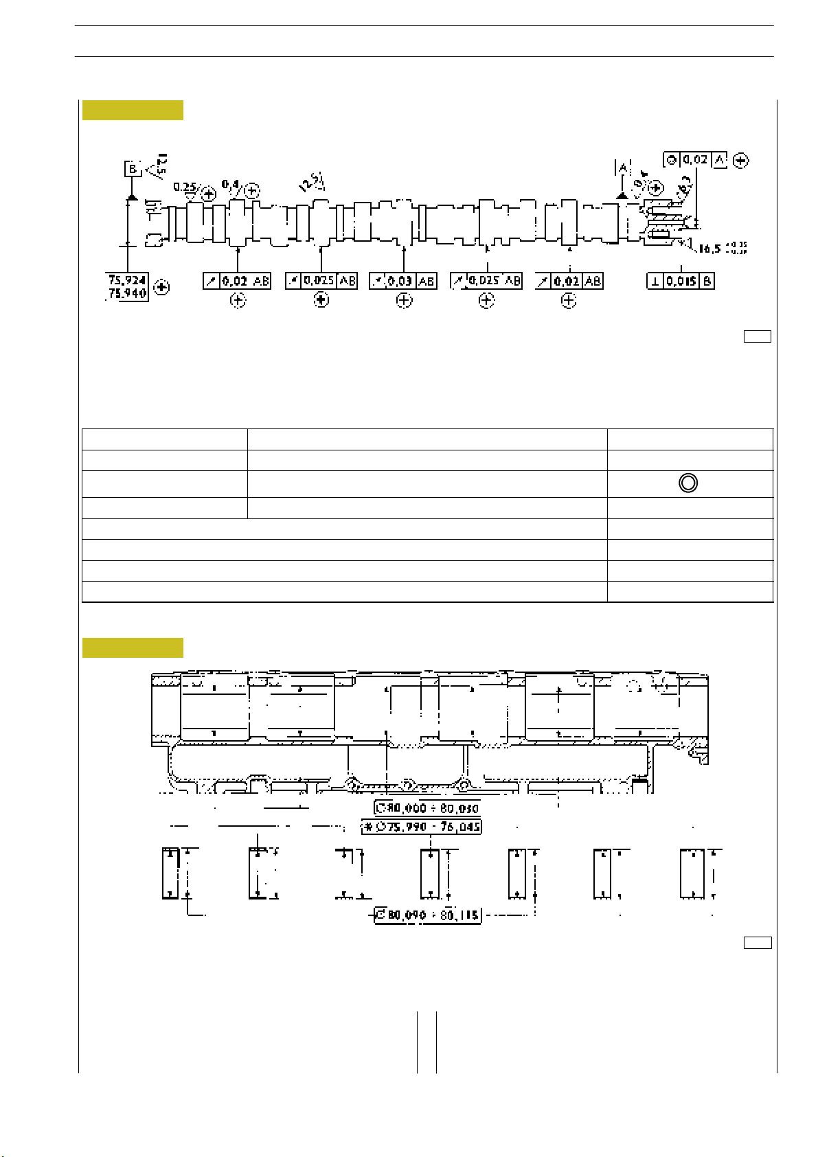
STRALIS AT/AD
ENGINE F2B
541210 Camshaft
Figure 123
47504
MAIN DATA - CAMSHAFT AND TOLERANCES
The surfaces of shaft supporting pin and cams must be extremely smooth; if you see any sign of seizing or scoring, replace the
shaft and the relative bushes.
TOLERANCES TOLERANCE CHARACTERISTIC SYMBOL
ORIENTATION Perpendicularity ⊥
73
POSITION Concentricity or coaxial alignment
OSCILLATION Circular oscillation ↗
IMPORTANCE CLASS ASSIGNED TO PRODUCT CHARACTERISTICS SYMBOL
CRITICAL
IMPORTANT ⊕
SECONDARY ⊝
541213 Bushes
Figure 124
47508
MAIN DATA - CAMSHAFT BUSHES AND RELATIVE BLOCK SEATS
* Bush inner diameter after installation
The bush surfaces must not show any sign of seizing or
scoring; if they do replace them.
Measure the bush inner diameters with a baremeter and replace
them, if the value measured exceeds the tolerance value.
To take down and fit back the bushes, use the proper tool
99360487.
Print 603.93.141 Base - January 2003
Page 99
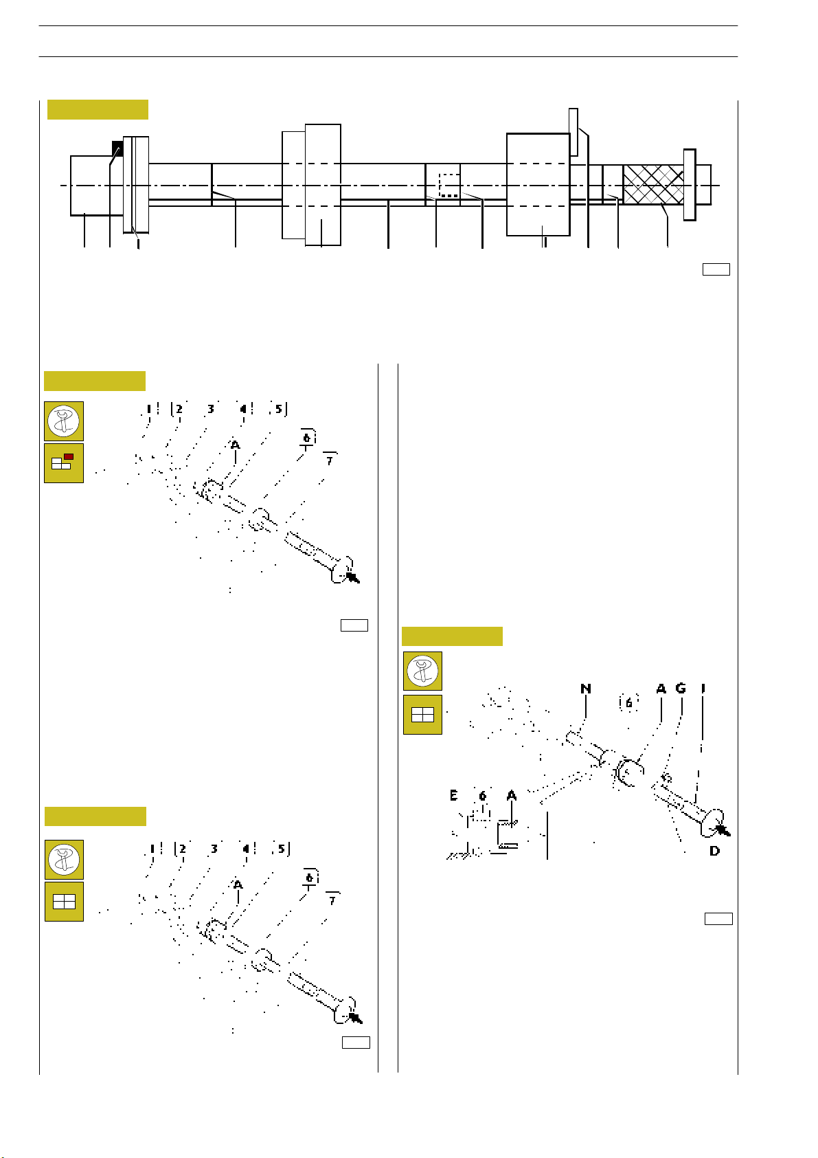
74
ENGINE F2B
541213 Replacing camshaft bushes using beater 99360487
Figure 125
S
TRALIS AT/AD
A
BC D E
F
DL
G
HD I
A. Drift with seat for bushings to insert/extract. - B. Grub screw for positioning bushings. - C. Reference mark to in sert
seventh bushing correctly. - D. Reference mark to insert bushings 1, 2, 3, 4, 5, 6 correctly (red marks). - E. Guide bushing. -
F. Guide line. - G. Guide bushing to secure to the seventh bushing mount. - H. Plate fixing yellow bushing to cylinder head.
-I.Grip.-L.Extensioncoupling.
Removal
Figure 126
Rear
71725
The sequence for removing the bushings is 7, 6, 5, 4, 3, 2, 1.
The bushings are extracted from the front of the single seats.
Removal does not require the drift extension for bushings 5,
6 and 7 and it is not necessary to use the guide bushing.
For bushings 1, 2, 3 and 4 it is necessary to use the extension
and the guide bushings.
Position the drift accurately during the phase of removal.
1 Position the bushing to insert on the drift (A) making the
grub screw on it coincide with the seat (B) (Figure 125)
on the bushing.
2 Position the guide bushing (E) and secure the guide
bushing (G) (Figure 125) on the seat of the 7
th
bushing
with the plate (H).
3 While driving in the bushing, make the reference mark (F)
match the mark (M). In this way, when it is driven home,
the lubrication hole on the bushing will coincide with the
oil pipe in its seat.
The bushing is driven home when the 1
st
red reference
mark (D) is flush with the guide bushing (G).
Figure 128
71721
Assembly
Figure 127
Rear
71723
To insert the bushing (6), proceed as follows:
- Unscrew the grip (I) and t he extension (N).
- Position the extension (N) and the guide bushing (E) as
showninthefigure.
Assemble the drift together with the extension.
77795
To insert bushings 1, 2, 3, 4 and 5, proceed as follows:
Base - January 2003 Print 603.93.141
- Repeatsteps1,2,3.
Page 100
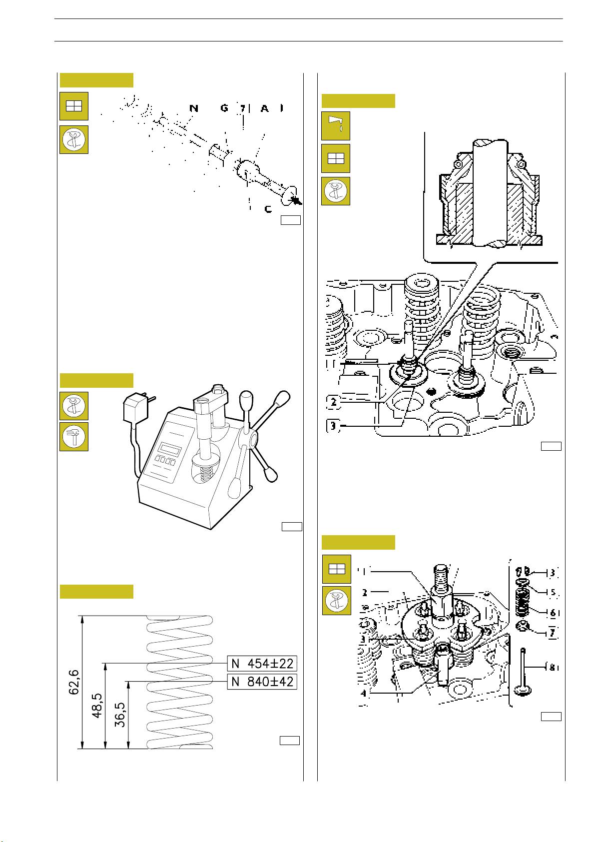
STRALIS AT/AD
ENGINE F2B
75
Figure 129
Rear
71724
To insert bushing (7), proceed as follows:
- Unscrew the grip (I) and t he extension (N).
- Refit th e guide (G) from the inside as shown in the figure.
- Position the bushing on the drift (A) and bring it close
up to the seat, making the bushing hole match the
lubrication hole in the head. Drive it home.
th
The 7
bushing is driven in when the reference mark (C)
is flush with the bushing seat.
540665 VALVE SPRINGS
Figure 130
Fitting the valves and oil seal ring
Figure 132
70000
Before assembly, the flexibility of the valve springs has to be
checked with the tool 99305047.
Compare the load and elastic deformation data with tho se
of the new springs given in the following figure.
Figure 131
Freespring height
Valve closed
Valve open
49034
MAIN DATA TO CONTROL EXHAUST AND
DISCHARGE VALVE SPRING
49033
Lubricate the valve stem and place the valves in the relevant
valve guides; install the lower plates (3) using tool 99360292,
fit the oil seal ring (1) on valve guides (2), then install the
valves as shown:
Figure 133
47583
- fit springs (6) and the upper plate (5);
- apply tool 99360264 (2) and block it with bracket (4);
tighten the lever (1) until cotters are installed (3),
remove tool (2).
Print 603.93.141 Base - January 2003
 Loading...