

Page 1
EUROCARGO
EURO 6
M E D I U M R A N G E
BODYBUILDERS INSTRUCTIONS
ISSUE 2013
Page 2

IVECO S.p.A
Technical Application & Homologation
Strada delle Cascinette, 424/34
10156 Torino (TO) - Italy
www.iveco.com
Printed 603.95.747 – 1
st
ed. 12/2013
Images and text: IVECO S.p.A. 2013
All rights reserved.
Page 3

EUROCARGO Euro 6 – GUIDELINES FOR TRANSFORMATION AND
GUIDELINES FOR TRANSFORMATION AND VERSIONS
UPDATE DATA
5
– Printed 603.95.747 – 1st Ed. - Base 12/2013
GUIDELINES FOR TRANSFORMATION AND VERSIONS
UPDATE DATA
Section Description Page Revision date
Page 4

- Printed 603.95.747 – Base 12/2013
Page 5
6
EUROCARGO Euro 6 – GUIDELINES FOR TRANSFORMATION AND
GUIDELINES FOR TRANSFORMATION AND VERSIONS
INTRODUCTION
– Printed 603.95.747 – 1st Ed. - Base 12/2013
INTRODUCTION
This publication provides information, features and instructions for transformation and fitting of the vehicle; considering the type of
content, it is meant for qualities and specialised staff.
The Bodybuilder is manager of the project and its execution, and must assure compliance with what is set forth in this publication
and in the laws in forth.
Any modification, transformation or fitting not provided by this manual and not expressly authorised, will result in exemption of any liability by IVECO and in particular, if the vehicle is covered by a guarantee, the immediate dissolution of the same.
This criterion also applies with regard to single units and components, those described in this manual have
been submitted by IVECO to for deliberations, approvals and inspections and belong to normal production.
The use of any type of unit not recognised (such as PTO, tyres, horns, etc.) relieves IVECO from any liability.
IVECO is available to provide information on the implementation of the interventions and to provide instructions for any cases and
situations not covered in this publication.
Before performing any operation, it is necessary to:
● verify that you have the manuals for the vehicle model on which you are about to work;
● ensure that all the safety devices (goggles, helmet, gloves, shoes, etc.), as well as the equipment used for work, lifting and trans-
port, is available and working;
● ensure that the vehicle is placed in safe conditions.
At the end of the operation, the operational, efficiency and safety conditions set by IVECO must be restored. Contact the Service
network for vehicle calibration if necessary.
Data and information contained in this publication may be outdated as a result of changes adopted by IVECO, at any time, for technical or commercial reasons or due to the need to adapt the vehicle to new legal requirements.
In the event of discordance between the information herein and the actual vehicle, please contact the Product Manager operating
on the market before performing any interventions.
SYMBOLS - WARNINGS
Danger for persons
Failure to comply with these prescriptions can result in the risk of serious injury.
Risk of serious damage to the vehicle
Partial or complete non observance of these prescriptions can lead to serious damages to the vehicle and can sometimes result in the
guarantee being voided.
General danger
Includes the dangers of both above described signals.
Environmental protection
Indicates correct behaviour in order that vehicle use is as environmentally friendly as possible.
NOTE Indicates an additional explanation for a piece of information.
Page 6

- Printed 603.95.747 – Base 12/2013
Page 7

INDEX OF SECTIONS
- Printed 603.95.747 – Base 12/2013
GENERAL INFORMATION 1
CHASSIS INTERVENTIONS 2
APPLICATIONS OF
SUPERSTRUCTURES 3
POWER TAKE-OFFS 4
ELECTRONIC
SUB-SYSTEMS 5
SPECIAL INSTRUCTIONS
FOR SCR EXHAUST SYSTEM 6
Page 8

- Printed 603.95.747 – Base 12/2013
Page 9

- Printed 603.95.747 – Base 12/2013
SECTION 1
GENERAL
INFORMATION
Page 10

- Printed 603.95.747 – Base 12/2013
Page 11

EUROCARGO Euro 6 – GENERAL INFORMATION
GENERAL INFORMATION
Contents
3
– Printed 603.95.747 – 1st Ed. - Base 12/2013
Contents
1.1 SCOPE OF THE GUIDELINES . . . . . . . . . . . . . 5
1.2 TECHNICAL DOCUMENTATION AVAILABLE
ELECTRONICALLY . . . . . . . . . . . . . . . . . . . . . . . 5
1.3 IVECO AUTHORISATION . . . . . . . . . . . . . . . 5
1.4 AUTHORISATION REQUEST . . . . . . . . . . . . . 6
1.5 RESPONSIBILITIES . . . . . . . . . . . . . . . . . . . . 6
1.6 LEGISLATIVE REQUIREMENTS . . . . . . . . . . . . 6
1.7 MULTI-STAGE APPROVAL - COLLABORATION
(only for EU countries, Switzerland and Turkey) . . . . . 6
1.8 GUARANTEES . . . . . . . . . . . . . . . . . . . . . . 7
1.9 QUALITY SYSTEM MANAGEMENT . . . . . . . . . . 8
1.10 ACCIDENT PREVENTION . . . . . . . . . . . . . . 8
1.11 CHOICE OF MATERIALS TO USE: ECOLOGY
- RECYCLING . . . . . . . . . . . . . . . . . . . . . . . . . . 8
1.12 VEHICLE MANAGEMENT ON THE PART OF
BODYBUILDER . . . . . . . . . . . . . . . . . . . . . . . . . 9
Acceptance of chassis . . . . . . . . . . . . . . . . . . . . 9
Maintenance . . . . . . . . . . . . . . . . . . . . . . . . . 9
Delivery of the vehicle to the final customer . . . . . 9
1.13 VEHICLE NAMES . . . . . . . . . . . . . . . . . . . 10
Commercial name . . . . . . . . . . . . . . . . . . . . . 10
1.14 TRADEMARKS AND SYMBOLS . . . . . . . . . . 11
1.15 DIMENSIONS AND GROUND . . . . . . . . . . 11
General information . . . . . . . . . . . . . . . . . . . . 11
Determination of the centre of gravity of the
superstructure and the payload . . . . . . . . . . . . . 12
Respect of the permitted masses . . . . . . . . . . . . 15
1.16 INSTRUCTIONS FOR PROPER
FUNCTIONING OF THE VEHICLE PARTS AND
ACCESSIBILITY . . . . . . . . . . . . . . . . . . . . . . . . 16
1.17 GENERAL REGULATION FOR THE
PREVENTION OF FIRE RISK . . . . . . . . . . . . . . . . 19
1.18 CONVENTIONS . . . . . . . . . . . . . . . . . . . 19
Page 12

4
EUROCARGO Euro 6 – GENERAL INFORMATION
GENERAL INFORMATION
– Printed 603.95.747 – 1st Ed. - Base 12/2013
Page 13

EUROCARGO Euro 6 – GENERAL INFORMATION
GENERAL INFORMATION
1.1 SCOPE OF THE GUIDELINES
5
– Printed 603.95.747 – 1st Ed. - Base 12/2013
GENERAL INFORMATION
1.1 SCOPE OF THE GUIDELINES
The scope of this publication is to provide information, features and instructions for fitting and transformation of the original
IVECO vehicle in order to ensure its functionality, safety and reliability.
These Guidelines also aim to indicate to Bodybuilders:
● the quality level to be obtained;
● obligations regarding the safety of operations;
● obligations regarding the objective responsibility of the product.
It should be noted that the collaboration with IVECO is based on the assumption that the Bodybuilder uses the maximum of their
technical and organisational skills and that operations are technically and perfectly complete. As outlined below, the topic is extensive and we can only provide the rules and minimum precautions that can allow development of the technical initiative.
Faults or defects caused by total or partial failure to comply with these Guidelines are not covered by the guarantee on the chassis
or relative mechanical units.
1.2 TECHNICAL DOCUMENTATION AVAILABLE ELECTRONICALLY
On the website www.ibb.iveco.com the following technical documentation is available:
● Guidelines for transformation and fitting of vehicles;
● technical specifications;
● truck diagrams;
● tractor diagrams;
● chassis diagrams;
● other range-specific data.
Requests to access the site must be made exclusively at www.ibb.iveco.com.
1.3 IVECO AUTHORISATION
Modifications or fittings proved in these Guidelines and carried out in respect of the same do not require a specific authorisation.
On the other hand, IVECO authorisation is required to carry out:
● particular changes to the wheelbase;
● work on the braking system;
● modifications to the steering system:
● modifications to the stabiliser bars and suspensions;
● modifications to the cab, cab mounts, locking and tilting devices;
● modifications to intake, engine exhaust and SCR components;
● applications of retarders;
● power take-off applications;
● variations in tyre measurements;
● modifications to hook organisms (hooks, fifth wheels).
Page 14

6
EUROCARGO Euro 6 – GENERAL INFORMATION
GENERAL INFORMATION
1.4 AUTHORISATION REQUEST
– Printed 603.95.747 – 1st Ed. - Base 12/2013
1.4 AUTHORISATION REQUEST
Authorisation requests, when necessary, must be sent to the responsible IVECO Departments on the market.
The Bodybuilder must provide vehicle data (cab, wheelbase, overhang, chassis No.) and adequate documentation (drawings, calculations, technical report, etc.) showing the realisation, use and operating conditions of the vehicle. The drawings should evidence
everything that differs from these instructions.
The Bodybuilder will be responsible for obtaining final approval from the competent authority for completed operations.
1.5 RESPONSIBILITIES
The authorisations issued by IVECO are exclusively related to the technical/conceptual feasibility of the modification and/or fitting.
The Bodybuilder is therefore responsible for:
● the design;
● the choice of materials;
● the implementation;
● the compliance of the design and implementation to any specific indications provided by IVECO and the laws in force in the
countries where the vehicle is destined;
● effects on functionality, safety, reliability and, in general, good behaviour of the vehicle;
● the supply of spare parts for a minimum period of 10 years starting from the last fitting of an order and for all pieces and
components that are installed.
1.6 LEGISLATIVE REQUIREMENTS
The Bodybuilder must verify that the final product is compliant, without exception, to all applicable legal requirements, on the municipal/autonomous/national level of each State in which it is registered and/or will circulate (Highway code, Official Regulations, etc.)
and on the international level (European Union Directives, ONU/Geneva ECE Regulations, etc.). It is also necessary to comply with
all requirements for accident prevention, instructions for assistance, the environment, etc.
The regulations on accident prevention or the legal indications cited in these Guidelines may be considered the most important, but
are not meant in any way to replace or eliminate the obligation and responsibility of the Bodybuilder to stay properly informed.
For this reason, IVECO shall not be held liable for any consequences due to errors caused by insufficient knowledge or incorrect
interpretation of the legal provisions in force.
1.7 MULTI-STAGE APPROVAL - COLLABORATION (only for EU countries, Switzerland and
Turkey)
Attachment XVII of Directive 2007/46/EC concerns Multi-stage approval.
This procedure requires that each manufacturer is responsible for the approval and compliance of the production of systems, components and "separate technical units" produced by the same or applied to the vehicle.
The manufacturer of the vehicle is defined as first-stage manufacturer, while the bodybuilder is defined as Second-stage manufacturer
or that of the next stage.
Page 15

EUROCARGO Euro 6 – GENERAL INFORMATION
GENERAL INFORMATION
1.8 GUARANTEES
7
– Printed 603.95.747 – 1st Ed. - Base 12/2013
191319
Figure 1
1. IVECO
2. Dealer
3. Bodybuilder
4. Customer
Based on this Directive, IVECO (main vehicle manufacturer) and a Bodybuilder intending to launch the multi-stage approval process
must sign a specific Collaboration Contract, called Technical Agreement, which sets out the content and reciprocal obligations in
detail.
Consequently:
1. IVECO has the responsibility of providing, in the agreed form, the approval documents (EC/ECE approvals) and the technical
information necessary for the proper implementation of the fitting and/or transformation (manuals, drawings, specifications);
2. the Bodybuilder has the following responsibilities:
■ the design and implementation of modifications to the basic vehicle received from IVECO,
■ reattainment of approvals of systems already approved in a previous stage when, due to changes on the basic vehicle the
approvals need to be updated,
■ compliance with national/international laws and in particular the laws of the destination country, for all changes made,
■ presentation of the changes made to a technical service, for evaluation,
■ appropriate documentation of the changes made, in order to give objective evidence of compliance to the aforemen-
tioned provisions of law (e.g. approval documents/test reports).
Before signing the Technical Agreement IVECO reserves the right to visit the Bodybuilder, in order to verify qualifications to carry
out the fittings and/or processing for which the above collaboration is requested.
The contents of the Technical Agreement can be evaluated in detail upon request to the Manager for relations with the Bodybuilder
for the single Market.
1.8 GUARANTEES
The guarantee that the work has been performed to standard must be given by the Bodybuilder who made the superstructure or
modifications to the chassis, in full compliance with the instructions in these Guidelines.
IVECO reserves the right to void the guarantee on the vehicle, if:
● unauthorised fittings or transformations have been carried out;
● a chassis not suitable for the fitting or intended use has been used;
● the standards, specifications and instructions, provided by IVECO for proper execution of the work, have not been respected;
● original spare parts or components made available by IVECO for specific operations have not been used;
● safety regulations have not been respected;
● the vehicle is used for purposes other than those for which it was designed.
Page 16

8
EUROCARGO Euro 6 – GENERAL INFORMATION
GENERAL INFORMATION
1.9 QUALITY SYSTEM MANAGEMENT
– Printed 603.95.747 – 1st Ed. - Base 12/2013
1.9 QUALITY SYSTEM MANAGEMENT
IVECO has always promoted the training and development of a Quality System for Bodybuilders.
This requirement is not only due to regulations on product liability, but also to the increasingly higher quality level demands, new
organizational forms in various sectors and the search for more advanced levels of efficiency.
IVECO therefore considers it appropriate for Bodybuilders to be equipped with:
● organizational charts for roles and responsibilities;
● quality objectives and indicators;
● design technical documentation;
● process documentation, including controls;
● plan for product improvement, also obtained through corrective actions;
● post-sales assistance;
● training and qualification of staff.
The availability of ISO 9001 certification, even though not required, is considered very important by IVECO.
1.10 ACCIDENT PREVENTION
Do not allow unauthorised staff to intervene or operate on the vehicle.
It is forbidden to use the vehicle with safety devices that have been tampered with or are damaged.
▶ Structures and devices installed on the vehicle must comply with the applicable regulations for
accident prevention, and with safety regulations required in the individual countries where the
vehicles will be used.
All precautions dictated by technical knowledge must be taken to avoid damage and functional defects.
Compliance with these requirements must be overseen by the builders of the structures and devices.
▶ Seats, coatings, gaskets, protective panels, etc., may pose a fire hazard when exposed to an in-
tense heat source. Remove them before working with welding and with flames.
1.11 CHOICE OF MATERIALS TO USE: ECOLOGY - RECYCLING
In the study and design phase, the choice of materials to be used by be made carefully, even from the ecological and recycling point
of view.
To this regard, please note that:
● it is forbidden to use materials that are harmful to health, or at least which may pose a risk, such as those containing asbestos,
lead, halogen additives, fluorocarbons, cadmium, mercury, hexavalent chromium, etc.;
● it is advisable to use materials whose processing produces limited waste quantities and allows easy recycling after first use;
● in synthetic materials of the composite type, it is advisable to use components that are compatible with each other, allowing
use with the possible addition of other recovery components. Prepare the required markings in accordance with the regulations in force;
● the batteries contain substances that are very dangerous for the environment. To replace the batteries it is possible to go to
the Service Network, equipped for disposal in accordance with the nature and the law.
▶ To comply with Directive 2000/53 EC (ELVs), IVECO prohibits the in-vehicle installation of com-
ponents that contain lead, mercury, cadmium and hexavalent chromium; exceptions are made
in cases allowed by Annex II of the above Directive.
Page 17

EUROCARGO Euro 6 – GENERAL INFORMATION
GENERAL INFORMATION
1.12 VEHICLE MANAGEMENT ON THE PART OF BODYBUILDER
9
– Printed 603.95.747 – 1st Ed. - Base 12/2013
1.12 VEHICLE MANAGEMENT ON THE PART OF BODYBUILDER
Acceptance of chassis
The Bodybuilder receiving a chassis/vehicle from IVECO or from a Dealer must perform a preliminary check, notifying of any missing accessories or damage attributable to the transporter.
Maintenance
To preserve the chassis/vehicle in its full efficiency, even while parking in the warehouse, maintenance operations may be necessary
within a predetermined time.
The expenses for carrying out these operations are borne by the owner of the vehicle in that moment (Bodybuilder, Dealer or
Customer).
▶ In case of long periods of vehicle inactivity, it is advisable to disconnect the negative pole of the
battery to maintain optimal charging status.
Delivery of the vehicle to the final customer
Before delivering the vehicle, the Bodybuilder must:
● calibrate its production (vehicle and/or equipment) and verify functionality and safety;
● carry out the controls set forth in the Pre-Delivery Inspection (PDI) list available in the IVECO network, for the items being
worked on (obviously the other items of the PDI will be the responsibility of the Dealer, such as the guarantee pamphlet);
● measure battery voltage with a digital multimeter (2 digit decimal), keeping in mind that:
1. optimal value is equal to 12.5 V,
2. between 12.1 V and 12.49 V the battery should be put under a slow charge,
3. with values less than 12.1 V the battery should be replaced.
Note
The batteries must be maintained at regular intervals (refer to IVECO Std 20-1812 and/or IVECO Std 20-1804) until delivery of
the vehicle to the Customer/Dealer to avoid problems of insufficient charging, short circuit or corrosion.
IVECO reserves the right to nullify the guarantee on the battery if the prescribed maintenance procedures are not respected.
● carry out a functional road test (in case of vehicle transformation). Any defects or problems should be notified to the IVECO
Assistance Service to verify conditions for inclusion in the PDI costs;
● prepare and deliver to the final Customer the necessary instructions for service and maintenance of the fitting and any added
units;
● report new data on special labels;
● provide confirmation that the operations carried out comply with the indications of the vehicle Manufacturer and legal re-
quirements;
● draw up a guarantee covering the changes made.
Page 18

10
EUROCARGO Euro 6 – GENERAL INFORMATION
GENERAL INFORMATION
1.13 VEHICLE NAMES
– Printed 603.95.747 – 1st Ed. - Base 12/2013
1.13 VEHICLE NAMES
The commercial names (an example follows) of IVECO vehicles do not coincide with approval names.
Commercial name
EUROCARGO MLC 120 E 19 / P
● EUROCARGO – Vehicle name
● MLC – Cab type
MLC Short cab
MLL Long cab
MLD Double cab
● 120 – Gross mass - GVW Cabs (no/10 = weight in t)
60 4x2 trucks
65 4x2 trucks
75 4x2 trucks
80 4x2 trucks
90 4x2 trucks
100 4x2 trucks
110 4x2 - 4x4 trucks
120 4x2 trucks
140 4x2 trucks
150 4x2 - 4x4 trucks
160 4x2 trucks
180 4x2 trucks
190 4x2 trucks
● E – Range code
E Standard frame height
EL Optimal chassis height
● 19 – Engine power (no. x 10 = power in HP)
● / P – Version
– Rear mechanical suspension
P Rear air suspension
FP Front and rear pneumatic suspensions
R Towing vehicles
D Dual cab (6+1) with mechanical suspension
D/P Dual cab (6+1) with rear air suspension
K Tipping body with mechanical suspension
DK Tipping body with mechanical suspension
Page 19

EUROCARGO Euro 6 – GENERAL INFORMATION
GENERAL INFORMATION
1.14 TRADEMARKS AND SYMBOLS
11
– Printed 603.95.747 – 1st Ed. - Base 12/2013
1.14 TRADEMARKS AND SYMBOLS
Trademarks, symbols and names may not be altered or moved from their original placement, as the originality of the vehicle image
must be protected.
The application of transformation or fitting trademarks must be authorised. Their placement should not be in the immediate vicinity
of the IVECO trademark and symbols.
IVECO reserves the right to withdraw trademarks and symbols if the fitting or transformation present features that do not comply
with requirements; the Bodybuilder assumes full responsibility for the entire vehicle.
Instructions for additional units
For additional units, the Bodybuilder must provide all necessary maintenance instructions upon vehicle delivery.
All the units that make up the same order must be equipped with components of the same brand, model and quality.
1.15 DIMENSIONS AND GROUND
General information
The dimensions and masses of vehicles allowed on the axles are shown in the drawings, the technical descriptions and, more generally, on the documents on the official IVECO website. Defects refer to vehicles in their standard versions; the use of special equipment may lead to changes on the masses and their distribution on the axles.
Weighing of the chassis
It should be noted that variations are possible on the masses of the order of 5%.
For this reason, before carrying out the fitting, it is a good idea to determine the mass of the vehicle cab and its distribution on the
axles.
Vehicle adaptability
The vehicle adaptability limits for each model are mainly defined as:
● distribution of mass on the axles;
● width of mirrors adopted;
● rear under-run protection device position.
The positioning of lights and mirrors, normally set for widths of 2550 mm, is also suitable for special superstructures 2600 mm
wide (e.g. mini-vans).
Carriage space
In order to comply with Euro VI requirements, different mechanical units have greater dimensions and different positions on the
chassis regarding the previous series.
Because of this the carriage space moves a few centimetres towards the rear under-run protection bar and in some cases it reduces.
The following table summarises the cases:
Table 1.1 - Carriage space
Vehicle
Extra space occupied rear cab
Transfer
fitting
towards the bar
under-run protection
Reduction
body
Engines
E22/E25
Engines
E28/E32
60, 75, 80EL – – approx 15 mm –
80, 90, 100 70 mm – approx 158 mm –
Page 20
12
EUROCARGO Euro 6 – GENERAL INFORMATION
GENERAL INFORMATION
1.15 DIMENSIONS AND GROUND
– Printed 603.95.747 – 1st Ed. - Base 12/2013
Vehicle
Extra space occupied rear cab
Transfer
fitting
towards the bar
under-run protection
Reduction
body
Engines
E22/E25
Engines
E28/E32
110EL, 120EL, 120, 140, 150, 160 115 mm 115 mm approx 15 mm 115 mm (E28/E32)
180, 190EL – 80 mm approx 15 mm 80 mm
It will still be allowed to keep the same carriage space as the corresponding Euro V models: This is possible by increasing the height
of the counter chassis, sufficient to exceed any interference or by combining retracting and raising of the superstructure.
Determination of the centre of gravity of the superstructure and the payload
Positioning on the longitudinal plane
To determine the position of the centre of gravity of the superstructure and the payload, you can proceed according to the examples given below.
On the technical documentation for each model (cab version diagram), you can see the positions allowed by the vehicle in the
standard version. The masses and the positioning of the individual components of the vehicle are shown on the chassis and weight
allocation diagram.
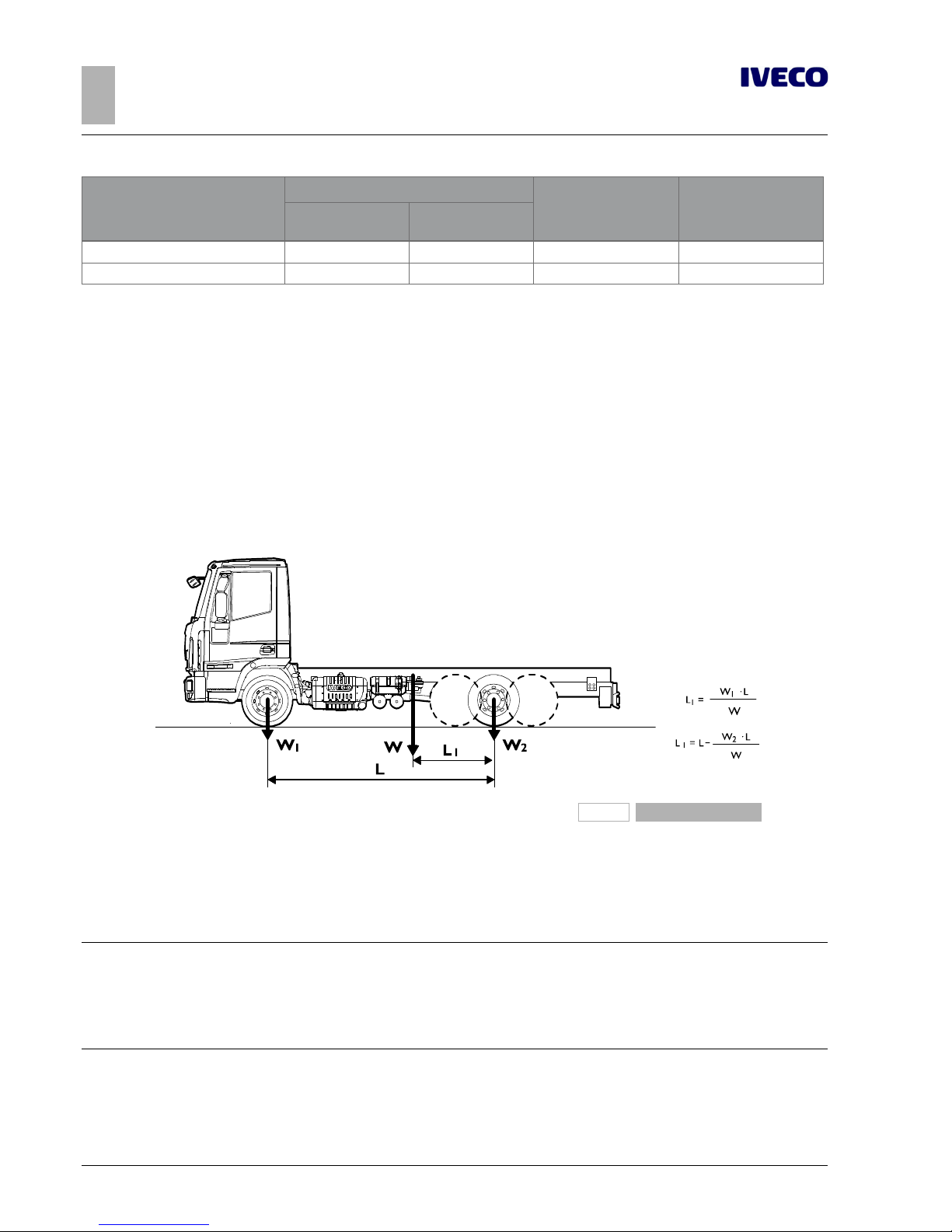
196789
Figure 2
Example to determine the placement of the centre of gravity of the payload plus superstructure (Vehicle with 2 axles;
vehicles with 3 axles having equal loads on two rear axles)
W = Payload plus superstructure
W1 = Measurement of payload on front axle
W2 = Measurement of payload on rear axle (or tandem)
L1 = Distance of centre of gravity from the centre line of the
rear axle (or tandem centre line)
L = Actual wheelbase
Note
For vehicles with three or more axes, with variable ratio of the distribution of the masses on the two rear axles depending on the
load, the "virtual" value of the wheelbase and the centre line between the axles must be determined for the respective load condition realized, using the instructions on the vehicle cab diagram.
This way, in particular version outfits (e.g. cranes on the rear overhang), the correct positioning can be determined for the centre of
gravity of the equipment and the payload, depending on the load carried (see Chapter 3.8).
For the purposes of breakdown of the payload on the axes, it should be considered that this is evenly distributed, except in cases in
which the shape of the load surface leads to a different load distribution.
For equipment, the centre of gravity is obvious considered for its actual position.
Page 21
EUROCARGO Euro 6 – GENERAL INFORMATION
GENERAL INFORMATION
1.15 DIMENSIONS AND GROUND
13
– Printed 603.95.747 – 1st Ed. - Base 12/2013
In the realisation of the superstructure or containers, automatic loading and unloading of the goods transported must be provided
to avoid excessive variations of the distribution and/or excessive loads on the axles, providing information for users if necessary.
The Bodybuilder should also provide a suitable anchoring systems for the load on the superstructure, so that transport can occur in
maximum security.
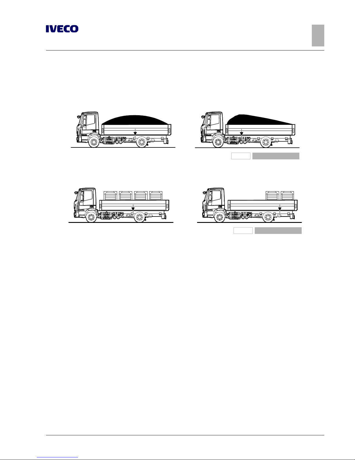
196790
Figure 3
Even distribution of load Uneven distribution of load
196791
Figure 4
Even distribution of load Uneven distribution of load (attention to loads on axles
and minimum ratio)
Height of centre of gravity
For the cab version and no-load vehicle, the value of the height of the centre of gravity is shown on the specific technical documentation for each model (cab version diagram).
For the vehicle complete with super structure and full load, this height must comply with the maximum values allowed by national
or international standards, in particular, Directives ECE 13 on longitudinal stability and ECE 111 on lateral stability while driving.
The following cases should be distinguished:
1. fixed loads,
2. mobile loads;
3. loads that result in increased aerodynamic actions.
Page 22
14
EUROCARGO Euro 6 – GENERAL INFORMATION
GENERAL INFORMATION
1.15 DIMENSIONS AND GROUND
– Printed 603.95.747 – 1st Ed. - Base 12/2013
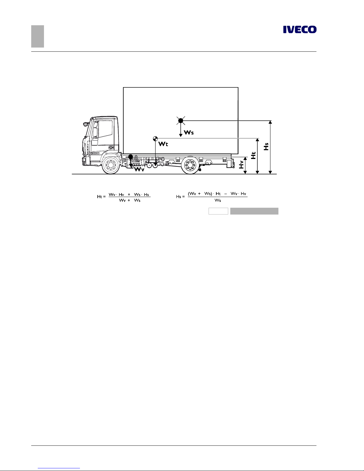
1. Fixed loads
196792
Figure 5
Control at full load
Hv = Vehicle centre of gravity height (loaded)
Hs = Height of payload centre of gravity from the ground
Ht = Complete full-load vehicle centre of gravity height
Wv = Vehicle tare weight
Ws = Payload
Wt = Complete vehicle ground at full load
For any inspections with the vehicle set up without payload you can proceed similarly, assuming Ws is only the tare weight of the
superstructure (considering for Hv a value appropriate for the load and between the no-load cab version trim and the full-load
trim).
2. Mobile loads
In the versions where the load can be moved laterally while cornering (e.g.: suspended loads, liquid transport, animal transport,
etc..) high lateral dynamic forces may be generated which may jeopardise the stability of the vehicle.
With reference to the indications of the regulation ECE 111, special attention should therefore be paid to:
● defining the height of the fitted vehicle's centre of gravity and at full load;
● assessing the dynamic forces and the lateral displacement of the centre of gravity;
● considering (for liquids) the density;
● prescribing the implementation of adequate precautions for driving.
Any cases where evaluation is difficult should be submitted to IVECO for approval.
Page 23

EUROCARGO Euro 6 – GENERAL INFORMATION
GENERAL INFORMATION
1.15 DIMENSIONS AND GROUND
15
– Printed 603.95.747 – 1st Ed. - Base 12/2013
3. Loads that result in increased aerodynamic actions
In outfits characterised by high vertical and surface development (e.g.: advertising panelling), the hight of the centre of thrust, determined in the case of cross-wind, must be evaluated very carefully.
▶ Even with the low centre of gravity, a vehicle fitting that has a high surface area may not provide
sufficient lateral stability and may be exposed to the danger of tilting.
Special attention must therefore be paid:
● in defining the height of the fitted vehicle's centre of gravity and at full load,
● in assessing the aerodynamic forces,
● prescribing the implementation of adequate precautions for driving.
Any cases where evaluation is difficult should be submitted to IVECO for approval.
implementation of stabiliser bars
The application of additional or reinforced stabiliser bars, where available, reinforcing the springs or rubber elastic elements (in
accordance with the procedure outlined in Section 2.7), may allow higher values of the centre of gravity of the payload, to be determined from time to time. The operation must be carried out after a careful evaluation of the features of the outfit, the wheelbase and the subdivision of lateral forces on the suspension, and should generally concern both the front and the rear. However,
it should be kept in mind that in many cases it is advisable to carry out the operation only on the rear axle; acting on the front axle
would give the driver an incorrect sensation of greater stability, making it actually harder to perceive the safety limit. Interventions
on the front axle can be made in the presence of concentrated loads behind the cab (e.g. cranes) or superstructures with high rigidity (e.g. vans).
Exceeding the limits
In the case of special transport with a high centre of gravity height (e.g., transport of machinery, indivisible loads, etc.), from a technical standpoint it is possible to exceed the values shown in the table, provided that the driving is adjusted appropriately (e.g. reduced speed, gradual variations of the trajectory of travel, etc.).
Respect of the permitted masses
All the limits shown on IVECO documentation must be respected. It is particularly important to evaluate the maximum ground on
the front axle in any load condition, in order to ensure the necessary steering features in all road surface conditions.
Special attention must therefore be paid to vehicles with concentrated load on the rear overhang (e.g.: cranes, tail lifts, central axle
trailers) and vehicles with a short wheelbase and high centre of gravity height (e.g. silo vehicles, concrete mixers).
Note
In the positioning of the auxiliary bodies and superstructure, a proper load distribution in the transverse direction must be ensured.
A variation on the nominal load may be permitted for each wheel (50% load on the corresponding axle) of±4% (e.g.: load allowed
on the axle 10,000 kg; allowed for each wheel side from 4,800 to 5,200 kg) in compliance with what is permitted by the tyres,
without affecting the braking and driving stability characteristics of the vehicle.
Unless otherwise specified individual vehicles, the minimum values of the mass on the front axle must be:
–
20% of the actual mass of the vehicle, if the load is evenly distributed,
–
25% of the actual mass of the vehicle, if the load is concentrated on the rear overhang.
Actual mass is meant to include any vertical load resulting from the trailer.
The rear overhang of the superstructure must be realized in observance of the admissible axle loads, the minimum required load
on the front axle, the length limits, positioning of the tow hook and under-run protection, provided for by the various Standards.
Page 24

16
EUROCARGO Euro 6 – GENERAL INFORMATION
GENERAL INFORMATION
1.16 INSTRUCTIONS FOR PROPER FUNCTIONING OF THE VEHICLE PARTS AND ACCESSIBILITY
– Printed 603.95.747 – 1st Ed. - Base 12/2013
Variations on permitted masses
Special exemptions from the maximum permissible masses may be granted for specific uses, for which, however, there are precise
limits for use and reinforcements to be made to parts of the vehicle.
These exceptions, if they exceed the limits of the law, must be authorised by the Administrative Authority.
In the authorisation request, you must indicate:
● type of vehicle, wheelbase, chassis number, intended use;
● division of the tare weight on the axles (in fitted vehicles, e.g.: crane with flatbed), with the position of the payload centre of
gravity;
● any proposals for strengthening the parts of the vehicle.
The permitted reduction of mass on vehicles (derating), can lead to interventions on some parts, such as suspension and brakes,
and may require a new calibration for the braking correction operation; in these cases the necessary indications may be provided.
1.16 INSTRUCTIONS FOR PROPER FUNCTIONING OF THE VEHICLE PARTS AND ACCESSIBILITY
In carrying out the transformations and applying any type of equipment, there should be no alteration to what enables the proper
functioning of the vehicle units and parts under various working conditions.
For example:
● free access must be guaranteed to the places that need inspection, maintenance or periodic controls (e.g., battery replace-
ment, access to the air suspension compressor) and, in the case of enclosed superstructures, special compartments and doors
should be provided;
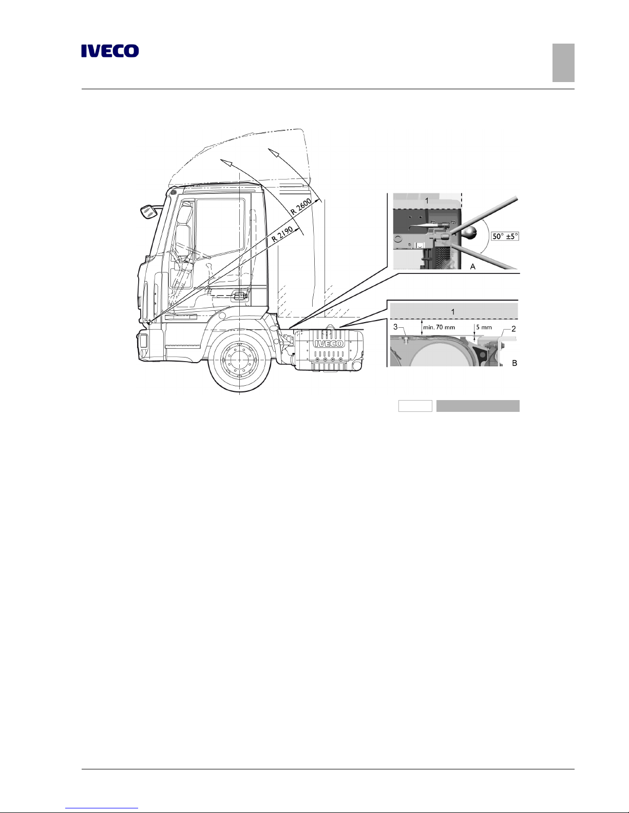
● it must be guaranteed the free tipping of the cab and the possibility of operating the relevant pump; in Figure 1-6 are shown
the longitudinal space and the rotation radius of the available cabs, as well as the angle that the bar inserted in the pump must
have without obstacles in relation to the upper limit of the counter chassis;
Page 25
EUROCARGO Euro 6 – GENERAL INFORMATION
GENERAL INFORMATION
1.16 INSTRUCTIONS FOR PROPER FUNCTIONING OF THE VEHICLE PARTS AND ACCESSIBILITY
17
– Printed 603.95.747 – 1st Ed. - Base 12/2013
196793
Figure 6
1. Possible fitting size limit
2. Upper chassis wire
3. Upper wire DPF/silencer
A. Right-hand side view
B. Left-hand side view
● the possibility of disassembly of the various units must be maintained for any support interventions (e.g. in figure 1-6 ref. B is
shown the case of the DPF / silencer assembly, with the minimum necessary dimension to allow the use of tools);
● in the fitting that provides the tipping of the lateral tails, consider the size of the most protruding parts of the vehicle, in order
to avoid limitations to tipping or damage to the parts.
Page 26
18
EUROCARGO Euro 6 – GENERAL INFORMATION
GENERAL INFORMATION
1.16 INSTRUCTIONS FOR PROPER FUNCTIONING OF THE VEHICLE PARTS AND ACCESSIBILITY
– Printed 603.95.747 – 1st Ed. - Base 12/2013
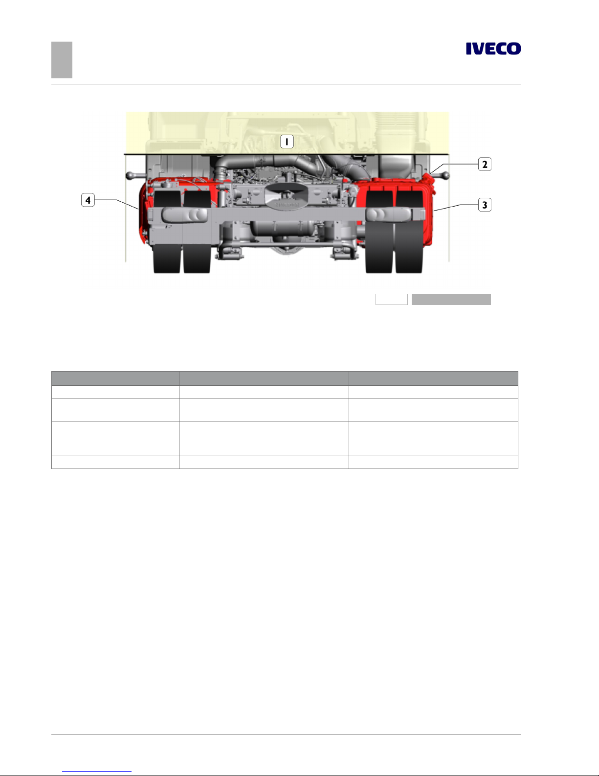
196798
Figure 7
1. Body surface
2. Lateral protrusion AdBlue tank
3. Lateral protrusion diesel oil pre-filter
4. Lateral protrusion silencer protection
Table 1.2 - Sizes of the most protruding units
Vehicle Y
max
left side member Y
max
right side member
From 60E to 100E 1125 mm 1125 mm - AdBlue cap
From 110EL to 160 E 1145 mm
1150 mm - pre-filter
1128 mm - AdBlue cap
180, 190EL 1125 mm
1160 mm - pre-filter (280 litre tank)
1150 mm - pre-filter (200 litre tank)
1128 mm - AdBlue cap
110W, 150W 1145 mm 1225 mm - pre-filter
● the possibility of disassembly of the various units must be maintained for any support interventions (e.g. in figure 6 ref. 2 is
shown the case of the DPF / silencer assembly, with the minimum necessary dimension for the correct use of the tools);
● conditions should not be affected regarding cooling (radiator grille, radiator, air passages, cooling etc.), fuel supply (pump posi-
tioning, filters, pipe diameter, etc.) and engine air intake;
● the soundproofing panels must not be altered or moved so as not to affect the approved sound emission limits. If any open-
ings need to be made (e.g. for the passage of pipes or added sections), they must be thoroughly closed, using fireproof and
soundproofing materials equivalent to the original materials used;
● adequate ventilation must be maintained for the brakes and battery casing (particularly in the execution of truck bodies);
● in the placement of fenders and wheel arches, free shaking of the rear wheels must be guaranteed, even under the conditions
of use with chains. It must also be guaranteed enough space for the lifting axle tyres. Some models include steering of the 3rd
axle in the raised position as well: respect the spaces necessary for this function (see Chapter 2.21);
● adjustment of the vehicle's headlamps must be checked once construction is completed, to correct any changes in their struc-
ture; for adjustment, proceed according to the instructions given in the "Use and Maintenance" manual;
● for any elements supplied loose (e.g. spare wheel, chocks), the Bodybuilder must position and fasten them in an accessible and
secure way, in compliance to any national regulations.
Page 27
EUROCARGO Euro 6 – GENERAL INFORMATION
GENERAL INFORMATION
1.17 GENERAL REGULATION FOR THE PREVENTION OF FIRE RISK
19
– Printed 603.95.747 – 1st Ed. - Base 12/2013
1.17 GENERAL REGULATION FOR THE PREVENTION OF FIRE RISK
Particular attention must be paid to prevent the spillage of hydraulic fluids or inflammable liquids above components which may
become hot or overheated.
Therefore, when pipes must be inevitably installed near the engine, exhaust system, catalytic converter or turbocharger, suitable
insulating shields or protective plates must be provided.
1.18 CONVENTIONS
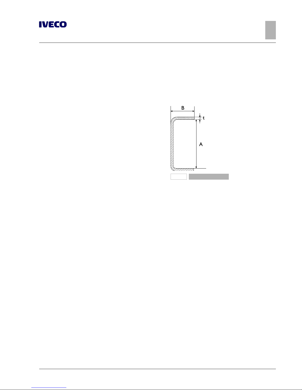
91473
Figure 8
In these Guidelines the following conventions are adopted:
● Wheelbase: distance between the centre lines of the first
steering axle and the first rear axle (engine or not).
● Rear overhang: distance between the centre line of the last
axle and the rear extremity of the chassis side members.
● Dimensions A, B and t of the chassis section: see the picture
on the side.
Page 28

20
EUROCARGO Euro 6 – GENERAL INFORMATION
GENERAL INFORMATION
– Printed 603.95.747 – 1st Ed. - Base 12/2013
Page 29

- Printed 603.95.747 – Base 12/2013
SECTION 2
CHASSIS
INTERVENTIONS
Page 30

- Printed 603.95.747 – Base 12/2013
Page 31

EUROCARGO Euro 6 – CHASSIS INTERVENTIONS
CHASSIS INTERVENTIONS
Contents
3
– Printed 603.95.747 – 1st Ed. - Base 12/2013
Contents
2.1 GENERAL CHASSIS MODIFICATION
STANDARDS . . . . . . . . . . . . . . . . . . . . . . . . . . . 5
Preventive measures . . . . . . . . . . . . . . . . . . . . 5
Characteristics of the material used in chassis
modifications . . . . . . . . . . . . . . . . . . . . . . . . . 6
Stresses on the chassis . . . . . . . . . . . . . . . . . . . 7
2.2 DRILLS ON THE CHASSIS . . . . . . . . . . . . . . . 7
Hole position and size . . . . . . . . . . . . . . . . . . . 8
Screws and nuts . . . . . . . . . . . . . . . . . . . . . . . 8
Welds . . . . . . . . . . . . . . . . . . . . . . . . . . . . . 9
Sealing holes by welding . . . . . . . . . . . . . . . . . 11
2.3 RUST AND PAINT PROTECTION . . . . . . . . . 11
Original vehicle parts . . . . . . . . . . . . . . . . . . . 11
Added or modified parts . . . . . . . . . . . . . . . . . 13
Precautions . . . . . . . . . . . . . . . . . . . . . . . . . 14
2.4 WHEELBASE MODIFICATION . . . . . . . . . . . 15
General information . . . . . . . . . . . . . . . . . . . . 15
Authorisation . . . . . . . . . . . . . . . . . . . . . . . . 15
Effects on steering . . . . . . . . . . . . . . . . . . . . . 15
Effects on braking . . . . . . . . . . . . . . . . . . . . . 16
Intervention procedure . . . . . . . . . . . . . . . . . . 16
Checking chassis stress . . . . . . . . . . . . . . . . . . 16
Cross members . . . . . . . . . . . . . . . . . . . . . . 17
Gearbox modifications . . . . . . . . . . . . . . . . . . 17
2.5 REAR OVERHANG MODIFICATION . . . . . . . 17
General information . . . . . . . . . . . . . . . . . . . . 17
Authorisation . . . . . . . . . . . . . . . . . . . . . . . . 18
Chassis Shortening . . . . . . . . . . . . . . . . . . . . 18
Elongation . . . . . . . . . . . . . . . . . . . . . . . . . . 18
2.6 INSTALLING THE TOW HOOK . . . . . . . . . . 20
General information . . . . . . . . . . . . . . . . . . . . 20
Precautions for Installation . . . . . . . . . . . . . . . 20
Towing hooks for conventional trailers . . . . . . . . 22
Drawbar couplings for centre axle trailers . . . . . . 22
Rear crossbar in lowered position . . . . . . . . . . . 28
2.7 ASSEMBLING AN ADDITIONAL AXLE . . . . . . 33
General information . . . . . . . . . . . . . . . . . . . . 33
Reinforcements on the chassis . . . . . . . . . . . . . 33
Added axle . . . . . . . . . . . . . . . . . . . . . . . . . 34
Steering axles . . . . . . . . . . . . . . . . . . . . . . . . 35
Suspension . . . . . . . . . . . . . . . . . . . . . . . . . 35
Stabiliser bars . . . . . . . . . . . . . . . . . . . . . . . . 36
Attachments to the chassis . . . . . . . . . . . . . . . 36
Brake system . . . . . . . . . . . . . . . . . . . . . . . . 36
Lifting device . . . . . . . . . . . . . . . . . . . . . . . . 37
2.8 GEARBOX MODIFICATION . . . . . . . . . . . . 37
Lengths allowed . . . . . . . . . . . . . . . . . . . . . . 38
Positioning the sections . . . . . . . . . . . . . . . . . 40
2.9 MODIFYING THE ENGINE AIR INTAKE AND
EXHAUST SYSTEMS . . . . . . . . . . . . . . . . . . . . . 43
Intake . . . . . . . . . . . . . . . . . . . . . . . . . . . . 43
Engine exhaust . . . . . . . . . . . . . . . . . . . . . . . 44
2.10 MODIFYING THE ENGINE COOLING
SYSTEM . . . . . . . . . . . . . . . . . . . . . . . . . . . . . 44
2.11 INSTALLING AN ADDITIONAL HEATING
SYSTEM . . . . . . . . . . . . . . . . . . . . . . . . . . . . . 45
2.12 INSTALLING AN AIR CONDITIONING
SYSTEM . . . . . . . . . . . . . . . . . . . . . . . . . . . . . 46
2.13 WORK ON THE CAB . . . . . . . . . . . . . . . . 46
General information . . . . . . . . . . . . . . . . . . . . 46
Work on the roof . . . . . . . . . . . . . . . . . . . . . 47
Spoiler or top-sleeper installation . . . . . . . . . . . 47
Realization of sleeper cabs . . . . . . . . . . . . . . . . 47
2.14 CHANGING TYRE SIZE . . . . . . . . . . . . . . . 48
2.15 WORK ON THE BRAKING SYSTEM . . . . . . 49
General information . . . . . . . . . . . . . . . . . . . . 49
Brake pipes . . . . . . . . . . . . . . . . . . . . . . . . . 49
ABS electronic brake control devices . . . . . . . . . 52
Withdrawing air from the cooling system . . . . . . 52
2.16 ELECTRICAL SYSTEM: CURRENT
INTERVENTIONS AND DRAWS . . . . . . . . . . . . . 53
Page 32

4
EUROCARGO Euro 6 – CHASSIS INTERVENTIONS
CHASSIS INTERVENTIONS
Contents
– Printed 603.95.747 – 1st Ed. - Base 12/2013
2.17 PART RELOCATION AND ANCHORAGE OF
ADDITIONAL UNITS AND EQUIPMENT . . . . . . . . 53
2.18 TRANSPORT OF HAZARDOUS MATERIALS
(ADR) . . . . . . . . . . . . . . . . . . . . . . . . . . . . . . 55
2.19 INSTALLING A RETARDER . . . . . . . . . . . . 57
2.20 REAR UNDER-RUN PROTECTION
(RUP) . . . . . . . . . . . . . . . . . . . . . . . . . . . . . . . 58
2.21 REAR MUD GUARDS AND WHEEL
ARCHES . . . . . . . . . . . . . . . . . . . . . . . . . . . . . 58
2.22 RAIN FLAP . . . . . . . . . . . . . . . . . . . . . . . 59
2.23 SIDE PROTECTIONS . . . . . . . . . . . . . . . . 59
2.24 FRONT UNDER-RUN PROTECTION
(FUP) . . . . . . . . . . . . . . . . . . . . . . . . . . . . . . . 61
2.25 REAR-VIEW MIRRORS . . . . . . . . . . . . . . . . 61
Page 33
EUROCARGO Euro 6 – CHASSIS INTERVENTIONS
CHASSIS INTERVENTIONS
2.1 GENERAL CHASSIS MODIFICATION STANDARDS
5
– Printed 603.95.747 – 1st Ed. - Base 12/2013
CHASSIS INTERVENTIONS
2.1 GENERAL CHASSIS MODIFICATION STANDARDS
Keep in mind that:
● weldings on the supporting structures of the chassis are absolutely forbidden (except as prescribed in Para-
graph"Weldings" ( ➠ Page 9) and in Chapters 2.4 ( ➠ Page 15), and 2.5 ( ➠ Page 17));
● no holes may be drilled into the side members (with exception to what is stated in Paragraphs "Weldings"
( ➠ Page 9) and "Choosing the type of connection" ( ➠ Page 11));
● for cases where modifications to nailed unions are allowed, the nails may be replaced with flanged head screws or with hex
head screws classed 8.8 with the next higher class diameter and nuts fitted with an anti-unscrewing system. Screws larger than
M14 may not be used (maximum hole diameter of 15 mm), unless otherwise specified;
● for cases where unions that require screws are restored, the suitability of these screws must be checked before being reused, and they must be tightened to the appropriate torque;
▶ As regards remounting safety components, it is prohibited to re-use the same screws and tight-
ening must be done at the specified torque (contact the Service Network for the value).
● for cases involving remounting of safety components where nails are replaced by screws, the union must be checked again
after about 500 - 1000 km of travel.
Preventive measures
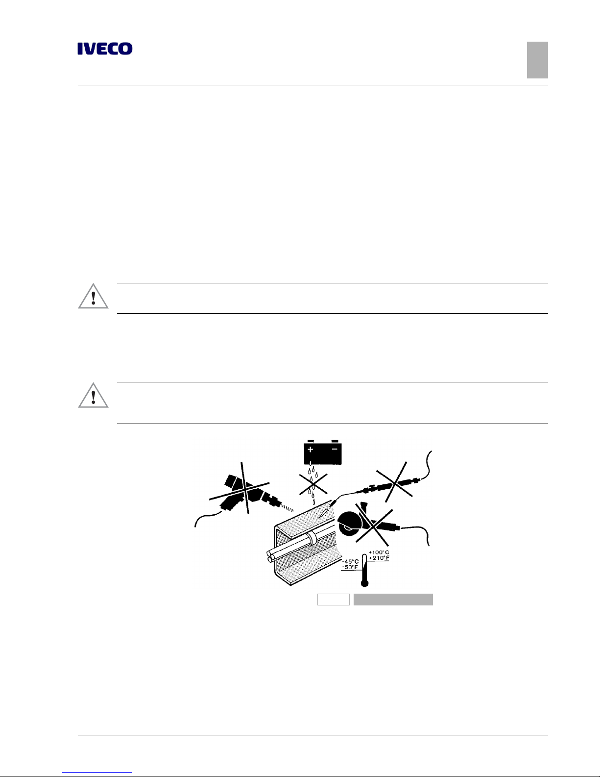
▶ When welding, drilling, milling and cutting near brake hoses and electrical wires, be sure to ad-
opt appropriate precautions for their protection; disconnect these parts if necessary (respect
the prescriptions in Chapters 2.15 and 5.7).
91444
Figure 1
Page 34
6
EUROCARGO Euro 6 – CHASSIS INTERVENTIONS
CHASSIS INTERVENTIONS
2.1 GENERAL CHASSIS MODIFICATION STANDARDS
– Printed 603.95.747 – 1st Ed. - Base 12/2013
Precautions for alternators and electric/electronic components
In order to avoid damage to the rectifier diode, the battery must never be disconnected (or the isolator switch opened) while the
engine is running.
In cases where the vehicle must be started by towing (strongly discouraged), make sure that the battery is charged and connected
so as to ensure minimum supply voltage to the engine ECU.
Recharge the battery only after disconnecting it from the vehicle circuit. In cases where the engine must be started-up with external charging equipment, be sure to avoid using the "start" function (if these devices feature this function) in order to avoid peak
currents that may damage electric and electronic components.
Start-up must be performed only via an external battery assembly, making sure that polarity is respected.
Earth connection
The original earth connections of the vehicle should never be altered; in cases where these connections must be moved or new
connections added, use the holes present on the chassis to the extent possible, taking care to:
● mechanically remove - either by filing and/or with a suitable chemical based solution - the paint on both the chassis and ter-
minal side, thus creating a contact surface free of indentations and edges;
● paint the area between the terminal and metal surface with a high conductivity paint (e.g. zinc coating Part Number IVECO
459622 from PPG);
● connect to earth within 5 minutes after application of the paint.
For ground connections at the signal level (e.g. sensors or devices with low absorption), absolutely never use standardised IVECO
M1 points (ground connection of the batteries), M2 or M8 (grounding the starter motor, depending on the position of the guide)
and connect the signal cable ground on points separate from the power cables and wires that serve as radio frequency screens.
Avoid earth connections between devices in a concatenated fashion for electronic equipment; install individual earth connections of
optimal length (favour the shortest routes).
Braking and electrical systems
For additional details on the braking and electrical systems see Chapters 2.15 ( ➠ Page 49) and 5.7 ( ➠ Page 36).
Characteristics of the material used in chassis modifications
For chassis modifications on the vehicle (all models and wheelbases) and for applications of reinforcements on the side members,
the material used must correspond to the original chassis material in terms of quality and thickness (see Tables 2.1 and 2.2).
If it is not possible to procure materials of the thickness indicated, materials having immediately higher standard thickness may be
employed.
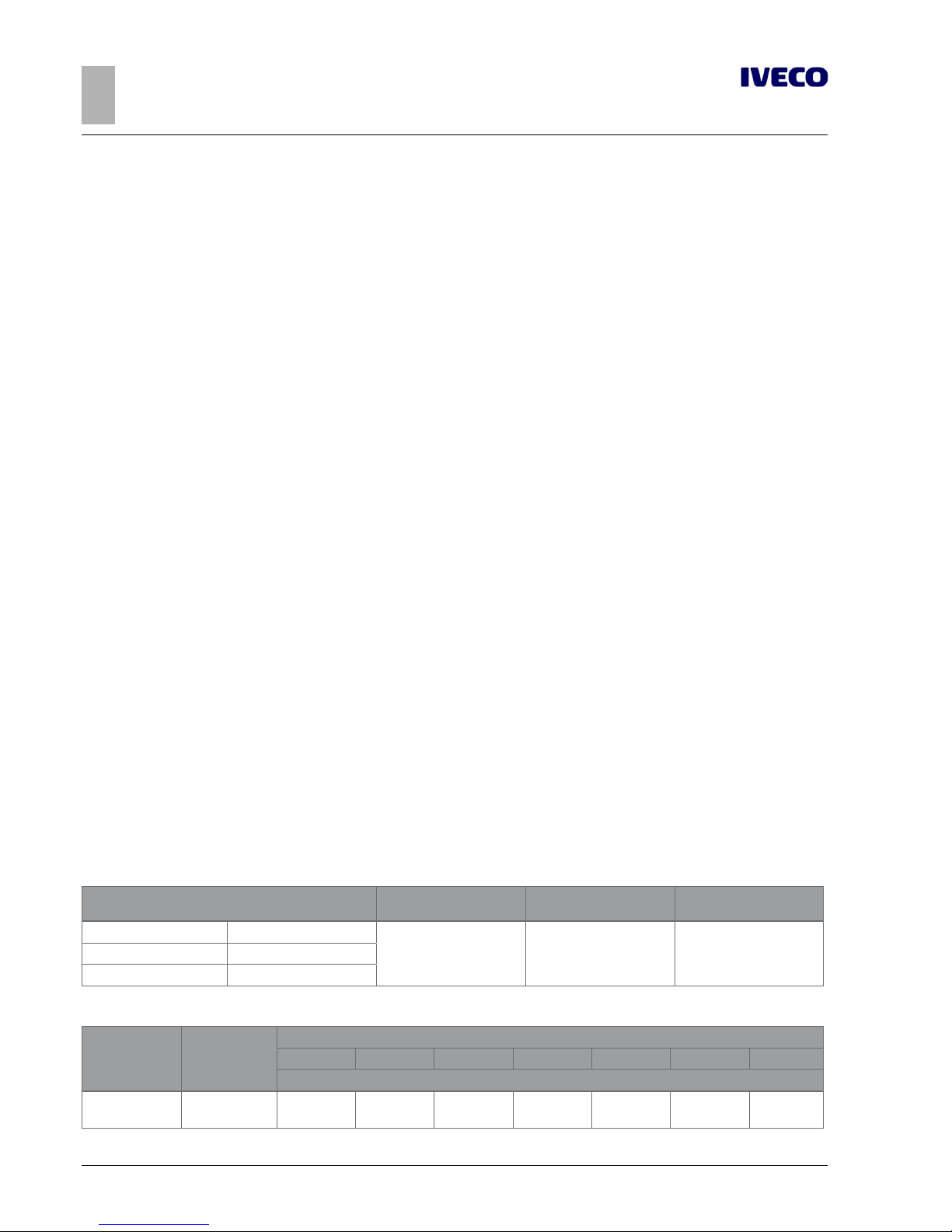
Table 2.1 - Material to be used in chassis modifications
Name of steel
Breaking strength
[N/mm2]
Yield stress
[N/mm2]
Elongation
IVECO Fe E420
530 420 21%Europe S420MC
Germany QStE420TM
Table 2.2 - Chassis side members sections
Model
A x B
[mm]
Wheelbase [mm]
2790 3105 3330 3690 4185 4455 4815
Thickness t [mm]
60E, 65E, 75E,
80EL
172.5x65 4 4 4 4 4 4 5
Page 35

EUROCARGO Euro 6 – CHASSIS INTERVENTIONS
CHASSIS INTERVENTIONS
2.2 DRILLS ON THE CHASSIS
7
– Printed 603.95.747 – 1st Ed. - Base 12/2013
Model
A x B
[mm]
Wheelbase [mm]
2790 3105 3330 3690 4185 4455 4815
Thickness t [mm]
80E, 90E, 100E 195x65 4 4 4 4 5 5 5
Model
A x B
[mm]
Wheelbase [mm]
3105 3330 3690 4185 4455 4590 4815 5175 5670 6210 6570
Thickness t [mm]
110EL, 120EL 195.5x65 5 5 5 6 6 – 6 – – – –
120E 240x70 5 – 5 5 6 – 6 6.7 6.7 – 6.7
140E
240x70
5
–
5 5
6 –
6
6.7
7.7
–
–
150E
5 6 6 6.7 6.7 7.7
160E
180EL
262.5x80 – – 6 7.7 – 7.7 7.7 7.7 7.7 7.7 7.7
190EL
Model
A x B
[mm]
Thickness t [mm]
3240 3690 3915 4150
Wheelbase [mm]
110EW
240x70
6 6 6 6
150EW 6 6 6 6
Stresses on the chassis
The following stress value in static conditions cannot be exceeded for any reason whatsoever:
Note
static stress σ allowed on chassis: 120 N/mm
2
In any case, respect any more restrictive limits placed by national standards.
Welding causes material property deterioration; therefore, when checking stresses in thermally altered zones, a resistance reduction of 15% must be accounted for.
2.2 DRILLS ON THE CHASSIS
Installation of auxiliary equipment onto the chassis must be done using the factory drilled holes whenever possible.
▶ It is strictly forbidden to drill holes into the side member flaps, with exception to what is indic-
ated in Chapter 3.3 - Paragraph "Choosing the type of connection".
When new holes must be made for specific applications (installation of shelves, corner shelves, etc.), these must be drilled into the
upright rib of the side member and must be thoroughly de-burred and bored.
Page 36
8
EUROCARGO Euro 6 – CHASSIS INTERVENTIONS
CHASSIS INTERVENTIONS
2.2 DRILLS ON THE CHASSIS
– Printed 603.95.747 – 1st Ed. - Base 12/2013
Hole position and size
The new holes must not be drilled into the areas subjected to greater stresses (such as spring supports) or where the side member
section varies.
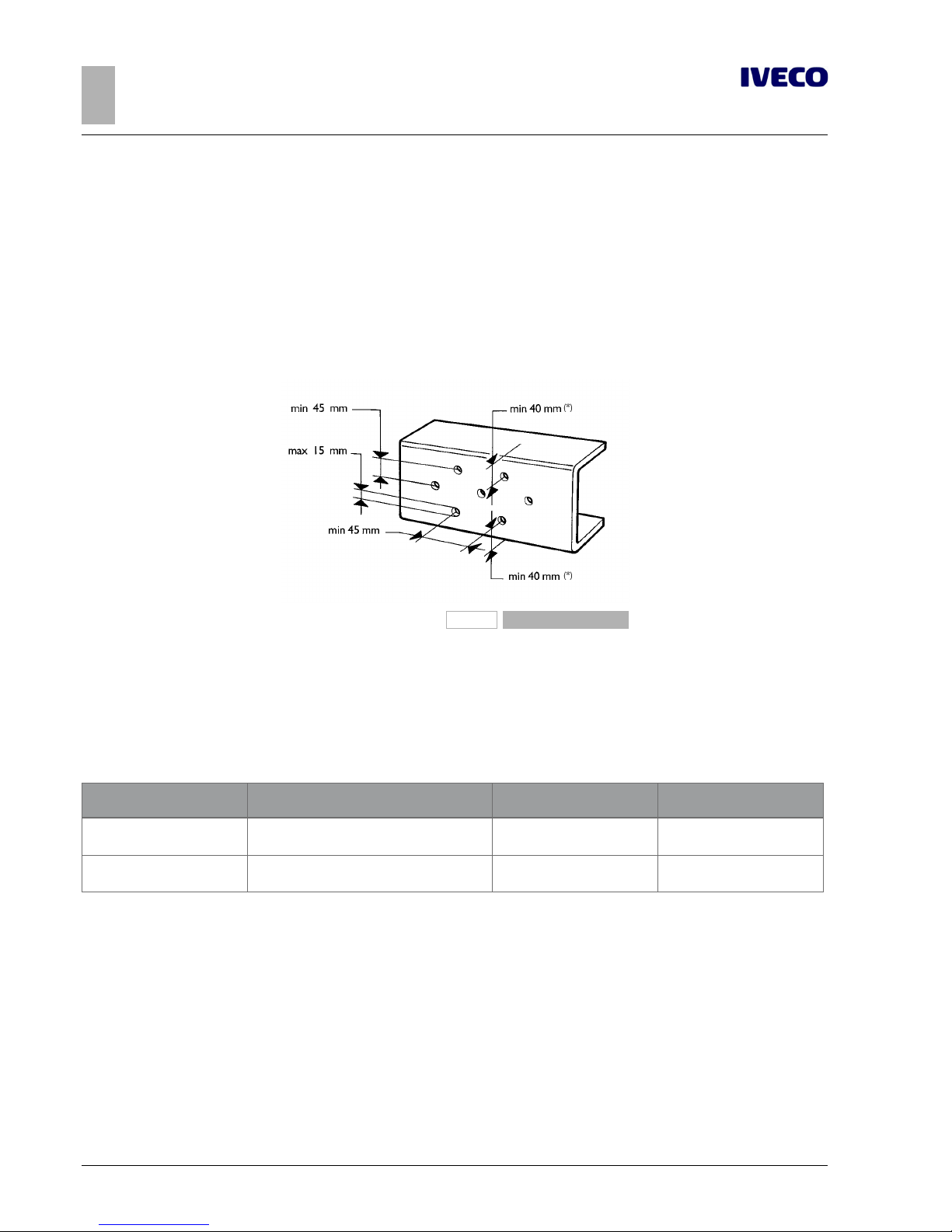
Hole diameter must be suited to sheet metal thickness but cannot exceed 15 mm (unless otherwise stated). The distance of the
hole axle from the edge of the side member must never fall below 40 mm (for chassis with thickness of 7.7 mm) or 39 mm (for
chassis with thickness of 6.7 mm), likewise, the hole axes must not be at a distance of less than 45 mm from each other, or from
the axes of existing holes.
The holes must be offset as in Figure 2.2.
The original hole layout must be maintained when moving spring supports or crossbars.
192342
Figure 2
(*)
valid with chassis thickness 7.7 mm, with chassis thickness 6.7 mm the measurement is equal to 39 mm.
Screws and nuts
We generally recommend the use of the same type and class of screws and nuts as those employed for similar anchorages on the
original vehicle (see Table 2.3).
Table 2.3 - Screws resistance classes
Resistance class Use
Breaking strength
[N/mm2]
Yield stress
[N/mm2]
8.8
Intermediate resistance screws (crossbars, shear
resistant plates, brackets)
800 640
10.9
High resistance screws (springs supports, stabiliser
bars and shock absorbers)
1000 900
Screws classed 8.8 and 10.9 must be well cleaned and, for applications using a screw with a diameter of ≤ 6 mm; we recommend
protection FeZnNi 7 IV.
Screw treatment allowed is Geomet or zinc coating. Geomet treated screws are discouraged when using them in welding operations.
Use flange headed screws and nuts if there is sufficient space.
Use nuts with an anti-unscrewing system and keep in mind that the tightening torque must be applied to the nut.
Page 37
EUROCARGO Euro 6 – CHASSIS INTERVENTIONS
CHASSIS INTERVENTIONS
2.2 DRILLS ON THE CHASSIS
9
– Printed 603.95.747 – 1st Ed. - Base 12/2013
Welds
▶ When welding, drilling, milling and cutting near brake hoses and electrical wires, be sure to ad-
opt appropriate precautions for their protection; disconnect these parts if necessary (respect
the prescriptions in Chapters 2.15 and 5.7).
Welds are allowed:
● in side member unions for elongations or trimming;
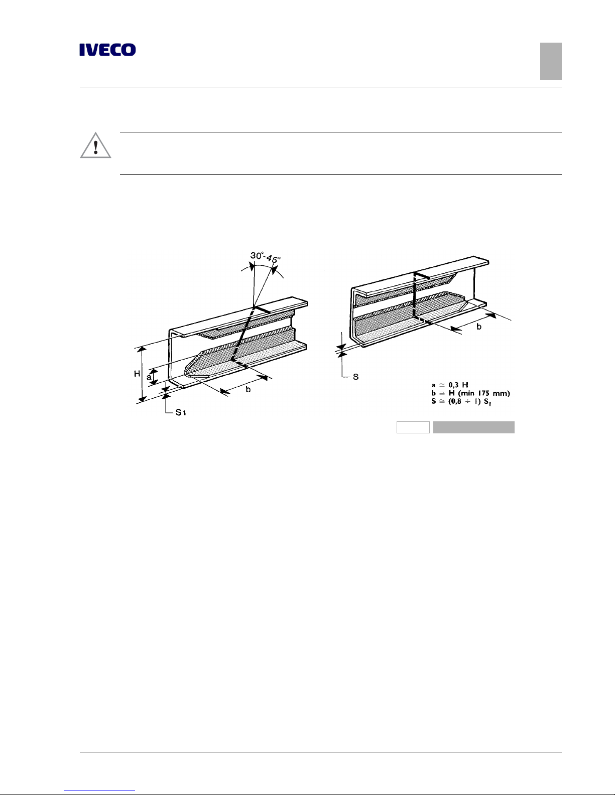
● in the application of corner reinforcements in the area regarding side member modification, as hereafter specified (see Figure
2.3).
91448
Figure 3
The following instructions must be respected when performing electric arc welding and in order to protect electrical components
and ECUs:
● before disconnecting the power cables ensure there are no active electric users;
● if an electric circuit breaker (main switch) is present, wait for it to complete the cycle;
● disconnect the negative pole from the battery;
● disconnect the positive pole of the battery without connecting it to earth; do NOT short-circuit the negative pole;
● disconnect all ECU connectors, proceed with caution and do not touch the ECU connector pins;
● disconnect the ECU from the vehicle for welds close to the ECU;
● connect the welder earth directly to the weld piece;
● protect the plastic pipes from heat and disconnect them if necessary;
● protect the surfaces of the leaf and air springs against any weld splashes when welds are performed nearby;
● avoid touching the spring leafs with the electrodes or pliers.
Page 38
10
EUROCARGO Euro 6 – CHASSIS INTERVENTIONS
CHASSIS INTERVENTIONS
2.2 DRILLS ON THE CHASSIS
– Printed 603.95.747 – 1st Ed. - Base 12/2013
Weld operations
● Thoroughly remove paint and rust from the chassis where welds will be made, as well as all parts that will be covered by rein-
forcements.
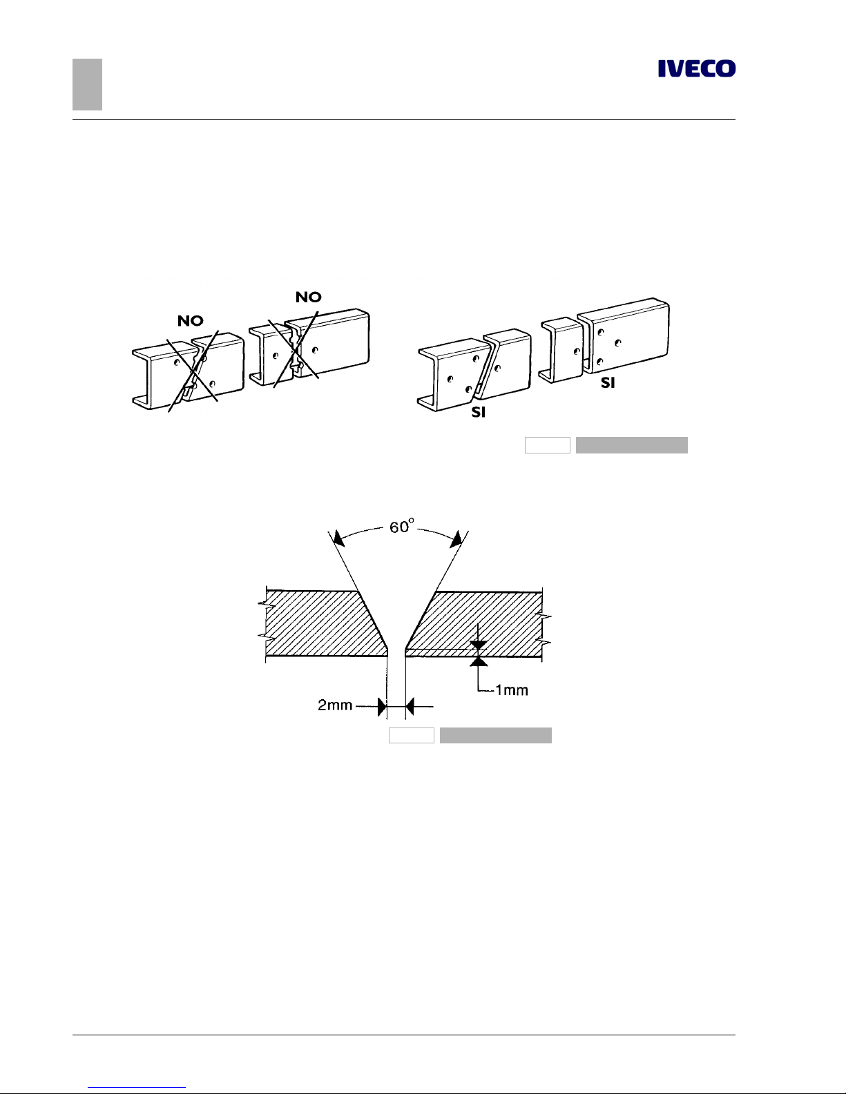
● Cut the side members with a skewed or vertical cut. The side members must not be cut at the points where the chassis con-
tour and width changes or where stress is greater (e.g. spring mounts). The cutting line must not go through the holes on the
side member (see Figure 2.4).
91446
Figure 4
● Make a 60 degree bevel cut on the internal part of the side member of the parts to join, for the entire length of the weld area
(see Figure 2.5).
91447
Figure 5
● Arc weld the area with multiple steps and use base electrodes that are thoroughly dried.
Avoid power overloads; the welds must be free of marginal incisions and slag.
● Start from the opposite end and weld as in the previous item.
● Let the side members cool slowly and in a uniform fashion. No cooling with air jets, water or other means is allowed.
● Grind off the excess material.
● Mount steel corner reinforcements that have the same characteristics as the chassis; the minimum indicative sizes are shown in
Figure 2.3.
Reinforcement anchorage must regard only the vertical rib of the side member and can be realised with a weld bead, staples,
bolts or nails (even Huck nails).
Area and length of the weld bead, number and distribution of staples, number of nails of bolts must be adequate to transmit
the bending and shearing moments.
● Once work is complete, use anti-rust protection (see Paragraph"Added or Modified Parts" ( ➠ Page 13)).
Page 39

EUROCARGO Euro 6 – CHASSIS INTERVENTIONS
CHASSIS INTERVENTIONS
2.3 RUST AND PAINT PROTECTION
11
– Printed 603.95.747 – 1st Ed. - Base 12/2013
Sealing holes by welding
If new holes are located near old holes (see Figure 2.2), these last can be welded shut.
Good results are obtained by:
● chamfering the outer edge of the hole;
● applying a copper plate on the inner edge of the side member to hold the welding material;
● welding the side member on both sides with elimination of all residual material.
Holes of 20 mm diameter can be sealed off by using chamfered washers welded on both sides.
2.3 RUST AND PAINT PROTECTION
Note
All components mounted on the chassis must be painted in compliance with IVECO Standard 18-1600 Colour IC444 RAL 7021 70/80 gloss.
Original vehicle parts
The following tables show, respectively, the classes of coating and protection required for the original vehicle components, the
protections required for the parts not painted or in aluminium and treatments required for the painted parts.
Table 2.4 - Class of protection - IVECO Standard 18 - 1600 (Prospectus I)
Class Part requirements Examples of parts involved
A Parts in direct contact with atmospheric agents
Bodywork - Rear-view mirrors - Windscreen wipers -
Metallic structured sun visors - Metallic bumpers -
Cab hook lock - Door stop device -
Bodywork fastening elements (screws, bolts, nuts, washers), etc.
B
B2
Parts in direct contact with atmospheric agents that mainly have
structural characteristics, in clear sight
Frame and relative parts, including its fasteners
Parts below the radiator grille (class B)
External cab ramps
B1 Only for rear axles and front axles
C Parts in direct contact with atmospheric agents, not in clear view Engine and relative parts
D Parts not in direct contact with atmospheric agents
Pedals - Seat coverings - Fastening elements - etc.,
mounted inside the cab
Table 2.5 - Various parts and components not painted and in aluminium - IVECO Standard 18 - 1600
(Prospectus IV)
Type of protection
IVECO
standard
Classes
A B - B1 - B2 C D
Stainless steel
(1)
18-0506 – – – –
Geomet
(2)
GEO 321-8
18-1101
yes –
– –
GEO 500-8
GEO 321-8 PM
GEO 321-8 PML
GEO 321-8 PL
GEO 500-8 PL
GEO 321-5
– yesGEO 500-5
GEO 321-5 PM
Page 40

12
EUROCARGO Euro 6 – CHASSIS INTERVENTIONS
CHASSIS INTERVENTIONS
2.3 RUST AND PAINT PROTECTION
– Printed 603.95.747 – 1st Ed. - Base 12/2013
Type of protection
IVECO
standard
Classes
A B - B1 - B2 C D
Geomet
(2)
GEO 321-5 PML
18-1101 –
yes
– –
GEO 321-5 PL
yes
Class B1
wheel studs
GEO 500-5 PL
Zinc coating
(3)
Fe/Zn 12 II
18-1102
– – yes yes
Fe/Zn 7 IV
Fe/Zn 12 IV
– – yes yes
Fe/Zn 7 IV LUB
Fe/Zn 7 IV S
– yes yes yes
Fe/Zn 12 IV S
Alloy Zn-Ni
Fe/Zn Ni 7 VII S
FIAT 9.57409 – yes yes yes
Fe/Zn Ni 7 IV
Aluminium
Anode oxidation 18-1148 yes
yes yes yes
Painting See Table III yes
(1)
Coupling with other materials must not cause the "battery effect”.
(2)
Coatings free from chromium salts.
(3)
Coatings free of hexavalent chromium.
Table 2.6 - Painted parts - IVECO Standard 18 - 1600 (Prospectus III)
Cycle phase description
Classes
A B
(8)
B1
(5)
B2 C D
MECHANICAL SURFACE
CLEANING
(1)
Sand/shot blasting –
yes
(*)
– yes
(*)
yes
(*)
yes
(*)
Brushing
yes
(*)
Sandpapering
PRE-TREATMENT
Iron phosphating
(only for non-precoated ferrous materials)
–
yes
(*)
– yes
(*)
yes
(*)
yes
(*)
Zinc phosphating
(**)
yes
CATAPHORETIC PAINTING
High thickness (30-40 μm)
yes
(2)
yes
(*)
(6)
–
yes
(*)
(6)
yes
(*)
(6) (9)
yes
(*)
(6)
Medium thickness (20-30 μm)
yes
(3)
Acrylic finishing (>35 μm)
– –
RUST PREVENTER
Bi-component (30-40 μm)
–
yes – yes
yes
(*)
(9)
yes
(*)
Single-component (30-40 μm) – yes –
ANTIROCK PRIMER
Single (130 °C) or bicomponent (30-40 μm)
yes
(3)
– – – – –
VARNISH
Single (130 °C) or bicomponent (30-40 μm)
yes
yes
(*)
–
– yes
(*)
yes
(*)
(7)
Powders (40-110 μm)
yes
(4)
Low temperature single-component (30-40 μm)
– – yes
(1)
This operation must be performed when dealing with cutting burr, oxidation, weld slag, or laser-cut surfaces.
(2)
Two-layer bodywork cycle.
(3)
Three-layer bodywork cycle.
(4)
In alternative to single and bi-component paint only for particular bodywork (windscreen wipers, rear-view mirrors, etc.).
(5)
Only rear/front axles.
Page 41

EUROCARGO Euro 6 – CHASSIS INTERVENTIONS
CHASSIS INTERVENTIONS
2.3 RUST AND PAINT PROTECTION
13
– Printed 603.95.747 – 1st Ed. - Base 12/2013
(6)
Excluding parts that cannot be immersed in pre-treatment baths or undergo painting because of compromised functionality (e.g.: mech-
anical parts).
(7)
Only if the colour is defined in a drawing according to I.C.
(8)
For fuel tanks in ferrous or pre-coated sheets.
(9)
Only parts to mount on the engine.
(*)
Alternative products and cycles for the same phase under the condition of comparability with the part to treat.
(**)
Specific phosphates must be used for zinc coated or aluminium sheets.
Added or modified parts
All vehicle parts (body, chassis, equipment, etc.) that are add-ons or subjected to modifications must be protected against oxidation
and corrosion.
Areas free of protection on ferrous materials are not accepted.
Tables 2.7 and 2.8 indicate the minimal treatment that modified or added components must receive when it is not possible to have
protection that is similar to that of original components. Different treatment is allowed if it ensures similar oxidation and corrosion
protection.
Do not used powder varnish directly after degreasing has been performed.
Lightweight alloy, copper and brass parts must be protected.
Table 2.7 - Painted modified parts or add-ons
Cycle phase description
Class
A - B -D
(1)
Mechanical surface cleaning
(including elimination of burrs/oxidation and cleaning of cut parts)
Brushing/sandpapering/sand blasting
Pre-treatment Degreasing
Rust preventer
Bi-component (30-40 μm)
(2)
Varnish
Bi-component (30-40 μm)
(3)
(1)
Modifications on rear axles, from axles and engine (classes B1 and C) not allowed
(2)
Preferably epoxy
(3)
Preferably polyurethane
Table 2.8 - Unpainted or aluminium modified parts or add-ons
Type of protection
Class
A - B
(1)
D
Stainless steel
yes
–
Geomet –
Zinc coating
(1)
– yes
(1)
Free from hexavalent chromium
Page 42

14
EUROCARGO Euro 6 – CHASSIS INTERVENTIONS
CHASSIS INTERVENTIONS
2.3 RUST AND PAINT PROTECTION
– Printed 603.95.747 – 1st Ed. - Base 12/2013
Precautions
On the vehicle
Appropriate precautions must be taken to protect parts on which paint could be harmful to the conservation and operation
thereof:
● hoses for pneumatic and hydraulic systems in rubber or plastic, with particular reference to the braking system;
● gaskets, rubber or plastic parts;
● drive shaft and PTO flanges;
● radiators;
● suspension, hydraulic/pneumatic cylinder stems;
● air vent valve (mechanical assembly, air tank, thermostarter preheat tanks, etc.)
● sediment bowl and fuel filter assembly;
● plates, codes.
If painting is required after wheels are removed, it is necessary to:
● Protect the wheel rim mounting surfaces on the hubs and the contact areas of the locking lugs/wheel studs;
● ensure adequate protection of brake discs.
The electronic components and modules must be removed.
Engines and their electric/electronic components
Appropriate precautions must be taken to protect:
● engine wiring and ground contacts;
● the sensor/actuator side connectors and wiring side;
● the sensors/actuators on the flywheel and on the flywheel rpm sensor mounting bracket;
● pipes (plastic and metal) of the fuel circuit;
● complete basic diesel filter;
● the ECU and its base;
● the entire internal part of the sound-proof cover (injectors, rails, pipes);
● the common rail pump and its control valve;
● the vehicle electric pump;
● tank containers;
● the front V-belts and relative pulleys;
● the power steering pump and relative pipes.
▶ When painting is complete and before oven drying (max. temperature 80 °C), the parts that risk
heat damage must either be removed or protected.
Page 43

EUROCARGO Euro 6 – CHASSIS INTERVENTIONS
CHASSIS INTERVENTIONS
2.4 WHEELBASE MODIFICATION
15
– Printed 603.95.747 – 1st Ed. - Base 12/2013
2.4 WHEELBASE MODIFICATION
General information
▶ Any wheelbase modifications that regard the electric circuits and/or relocation of the
electric/electronic components requires IVECO approval and must be carried out in compliance
with chapter 5.7 instructions.
Usually, wheelbase modification must be performed on the standard wheelbase that is closest to the target value.
If the dimensions of the superstructure are suitable, it is best to use wheelbases in standard production because this allows the use
of original drive shafts and pre-defined crossbar positions.
Nevertheless, IVECO must issue its authorisation for wheelbases below the minimum or maximum approved standard sizes on the
market.
Authorisation
Wheelbase variation in the 4x2 versions is allowed without IVECO authorisation only when:
● the target wheelbase is listed in the catalogue for the type of vehicle being transformed;
● the structure (area of side members; number, type and position of the crossbars), the existing circuits and systems on the
series chassis corresponding to this length will be replicated.
When these conditions do not exist in combination at the same time, which ensure that the schematics of the transformed frame is
equal to that of the original, the modification must undergo approval.
The workshop that performs the transformation must provide sufficient guarantees in terms of technology and inspections (qualified personnel, appropriate operational processes, etc.).
For the 4x4 versions, variation in the wheelbase is only allowed with specific approval from IVECO.
The operations must be performed in compliance with these directives, taking into account the suitable adjustments and adaptations, as well as all required precautions (e.g.: check whether the ECUs must be reparameterized, exhaust pipe adjusted, observance of minimum tare weight on the rear axle, etc.) provided for on the corresponding original wheelbases.
Effects on steering
Generally speaking, extending the wheelbase will have a negative effect on steering.
When required by standard, the maximum thresholds for cornering path, steering wheel force and relative time to negotiate
curves should not be exceeded (e.g.: ECE Regulation of EC Directive in force).
Table 2.9 lists the maximum wheelbase elongation values allowed for the vehicle with series steering, maximum load and tyres.
Longer wheelbases require approval and technical solutions must be adopted to improve steering, such as reduction of maximum
load on the front axle or the implementation of a caster trail with a restricted set of values.
The installation of an additional pump must also be authorised, while successive installations require the participation of the specialised Company.
Table 2.9 - Wheelbase lengthening with standard steering
Model Maximum Wheelbase [mm]
60E, 65E, 75E, 80EL 80E, 90E, 100E, 110EL, 120EL 5670
120E, 130E, 140E, 150E, 160E 6570
180E, 190EL 6700
110EW, 150EW 4500
For the pneumatic fitting see Chapter 2.14 ( ➠ Page 48).
Page 44

16
EUROCARGO Euro 6 – CHASSIS INTERVENTIONS
CHASSIS INTERVENTIONS
2.4 WHEELBASE MODIFICATION
– Printed 603.95.747 – 1st Ed. - Base 12/2013
Effects on braking
Generally speaking, shortening the wheelbase will have a negative effect on braking.
Contact the IVECO Department - Homologation & Technical Application to find out at what conditions (brake cylinders, minimum
tare, theoretically admissible loads, tyres, height of centre of gravity) transformation can be allowed.
▶ The changes of the wheelbase on vehicles equipped with ASR necessarily lead to the updating of
the setting parameters of its control unit.
Intervention procedure
Proceed as follows to obtain good results:
● position the vehicle so that the chassis is perfectly horizontal, use appropriate trestles;
● detach the drive shafts, braking system hoses, cables and all other equipment that may interfere with proper work execution;
● identify the reference points on the frame (e.g: guide holes, suspension supports);
● mark the reference points with a slight punch mark on the top flaps on both side members, after having verified that the con-
junction line is at a perfect right angle with the longitudinal axle of the vehicle;
● if moving the suspension supports, identify the new position using the previously determined references;
● make sure that the new measurements are identical on both the right and left sides; the diagonal check, for lengths of at least
1500 mm must not yield deviations of over 2 mm;
● make the new holes using as jig - if any other tools are unavailable - the supports and gusset plates of the crossbars;
● secure the supports and crossbars using nails or screws; if using screws, bore the holes and use calibrated screws class 10.9
with anti-unscrewing nuts; if size allows, flanged head screws may be employed;
● if cutting the frame (to be carried out according to indications of the second item in "Welding Operations" - Paragraph "Welding" ( ➠ Page 9)) mark a second line of reference points so that the work area is set between the two lines (plan for a distance of at least 1500 mm upon work completed). Carry over the points relative to the cutting area between the two lines;
proceed as instructed in Paragraph "Welding" ( ➠ Page 9);
● before welding, check that the side members and any added parts are perfectly aligned and perform the check measurements on both sides and along the diagonal line, as previously indicated. Apply the reinforcements as in Paragraph "Welding"
( ➠ Page 9).
Additional information
● Protect the surfaces against oxidation as in Paragraph "Added or modified parts" ( ➠ Page 13).
● Restore the braking and electrical systems as according to Chapters 2.15 ( ➠ Page 49) and 5.7 ( ➠ Page 36).
● Follow the instructions in Chapter 2.8 ( ➠ Page 37) for interventions on the transmission.
Checking chassis stress
With regard to wheelbase elongation, aside from local reinforcement in the joint area of the side members, the Bodybuilder must
also account for reinforcements - along the entire contour of the wheelbase - until achieving area strength modulus equal to
IVECO values for the same wheelbase or for the next admissible greater length. In alternative, for cases allowed by local standards,
larger counter-frame profiles can be adopted.
The Bodybuilder must make sure that the stress limits prescribed by national standards are respected. These stresses must not
be greater than those or the original wheelbase frame, assuming an evenly distributed load and considering the frame as a beam
positioned in place of the suspension supports.
When an elongation is performed starting from the longest original wheelbase, the reinforcements adopted must account for
wheelbase elongation, type of chassis produced and vehicle use.
Page 45
EUROCARGO Euro 6 – CHASSIS INTERVENTIONS
CHASSIS INTERVENTIONS
2.5 REAR OVERHANG MODIFICATION
17
– Printed 603.95.747 – 1st Ed. - Base 12/2013
Cross members
The need to apply one or more crossbars is subject to the amount of elongation, the positioning of the gearbox, the welding area,
the points of application of forces arising from the superstructure, and the conditions of use of the vehicle.
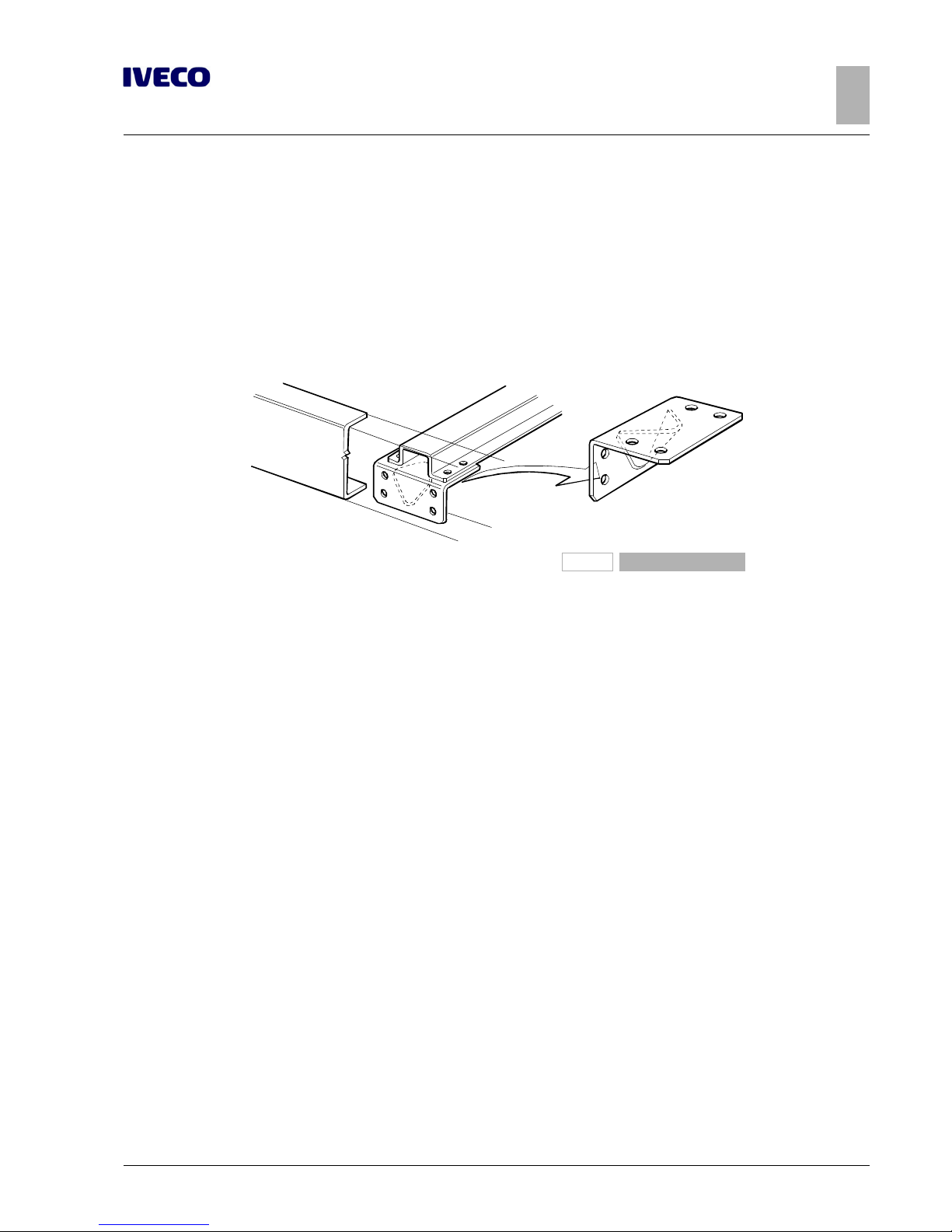
Any additional cross members must have the same characteristics of those already mounted on the frame (bending and torsion
strength, material quality, connection to side members, etc.). Figure 2.6 shows an example. In any case an additional crossbar must
be installed for elongations exceeding 600 mm.
The distance between the two cross members must generally be within 1000 ÷ 1200 mm.
The minimum distance between the cross members, especially for "heavy duty use" must not be less than 600 mm; this restriction
excluded "lightweight" cross member that acts as transmission and suspension supports.
91449
Figure 6
Gearbox modifications
See Chapter 2.8 ( ➠ Page 37) for checks of modifications allowed.
2.5 REAR OVERHANG MODIFICATION
General information
When modifying the rear overhang it is necessary to take note of the variations that this modification inflicts on distribution of
axle loads, in compliance with loads established by IVECO (see Chapter 1.15 ( ➠ Page 11)). Limits set by national law must also
be respected, as well as maximum distances from the rear structural edge and distance from ground, defined for towing hook and
under-run protection. The distance from the tip of the frame to the rear edge of the superstructure must, as a rule, not exceed
350 ÷ 400 mm.
If it is necessary to move the rear crossbar fixed using screws, it is necessary to maintain the same type of union as in the series
(number of screws, dimensions, strength class).
If a drawbar shall be attached, it is necessary to leave sufficient space (approx. 350 mm) between the rear crossbar and that
nearest, for any drawbar assembly/disassembly operations.
If all works are performed in a professional manner and according to the instructions contained herein, the original towing capacity
may remain the same.
In all cases, the parties performing the work shall be liable thereof.
Page 46

18
EUROCARGO Euro 6 – CHASSIS INTERVENTIONS
CHASSIS INTERVENTIONS
2.5 REAR OVERHANG MODIFICATION
– Printed 603.95.747 – 1st Ed. - Base 12/2013
Authorisation
Rear frame elongation as well as shortening to the smallest value for each model of the series do not require authorisation if performed in compliance with the instructions provided herein.
For vehicles destined to special uses, where load distribution is predefined and fixed, the rear overhand can be extended with values greater than 60% of the wheelbase, as long as the conditions stated in Chapter 1.15 ( ➠ Page 11), Directive CEE 97/27 and
their relative national laws are respected in terms of cornering path.
▶ If you need to adjust the length of the electrical circuits, see Chapter 5, "Special instructions for
electronic subsystems”.
Chassis Shortening
The last crossbar must be moved forward when shortening the rear overhang of the chassis.
When the rear crossbar is too close to another crossbar, the latter can be eliminated if it plays no role in suspension support.
Elongation
possible solutions concerning elongations are shown in Figures 2.7 and 2.8.
Cuts can be of straight type. The minimum dimensions of the reinforcements to apply in the area of modification are shown in
Figure 2.3.
The solution for elongations greater than 300 ÷ 350 mm is shown in Figure 7. In this case, the corner reinforcements, which also
serve as junction between cross member and frame, must have the same width and thickness of the original gusset plate. The union
between the cross member and plate, originally performed using nails, can be done with screws class 8.8 having the next largest
scale diameter and anti-unscrewing nuts.
When the connection between the cross and the gusset plate is made by welding, it may be connected to the gusset plate reinforcement by welding (see Figure 2.7).
The solution for elongations greater than 350 mm is shown in Figure 2.8.
Page 47
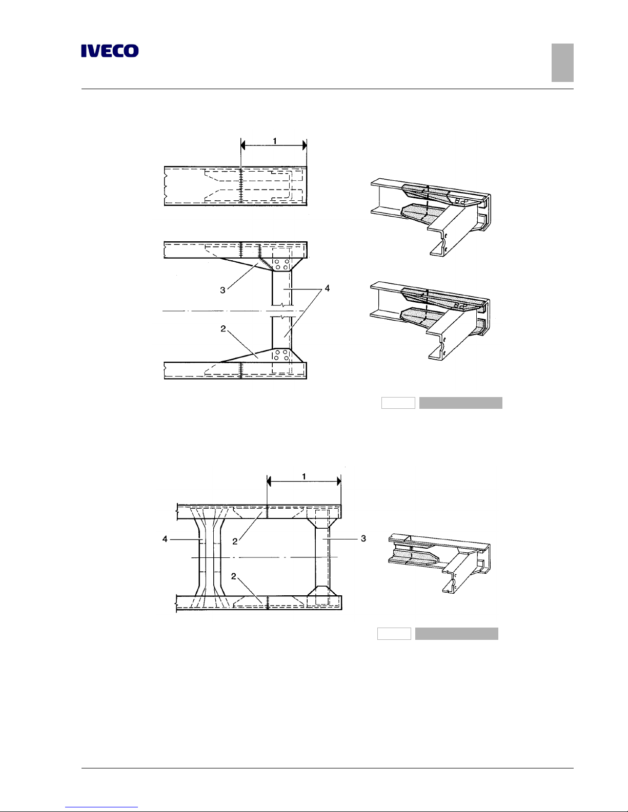
EUROCARGO Euro 6 – CHASSIS INTERVENTIONS
CHASSIS INTERVENTIONS
2.5 REAR OVERHANG MODIFICATION
19
– Printed 603.95.747 – 1st Ed. - Base 12/2013
91454
Figure 7
1. Added part
2. Reinforcing profile
3. Reinforcing profile (alternative solution)
4. Original rear cross member
91455
Figure 8
1. Added part
2. Reinforcing profile
3. Original rear cross member
4. Any additional cross member
When the elongation is rather large, the need of an additional crossbar must be evaluated on a case to case basis in order to ensure
proper torsional strength of the frame. The insertion of an extra crossbar having characteristics similar to the series is necessary,
however, when two cross members are spaced more than 1200 mm apart.
Page 48

20
EUROCARGO Euro 6 – CHASSIS INTERVENTIONS
CHASSIS INTERVENTIONS
2.6 INSTALLING THE TOW HOOK
– Printed 603.95.747 – 1st Ed. - Base 12/2013
2.6 INSTALLING THE TOW HOOK
General information
The application of a towing hook is possible without authorisations:
● on vehicles with the specifically prescribed crossbar (opt. 6151) for inertia trailers;
● on vehicles originally equipped with opt. 430 for adaptation to towing a trailer.
The installation on vehicles to which the drawbar coupling is not originally provided must be authorized by IVECO.
For trailers with one or more close axles (central axle trailers), taking into account the stresses to which the rear crossbar is subjected, particularly due to the dynamic vertical loads, keep in mind the precautions given in Paragraph "Towing hook for centre axle
trailers" ( ➠ Page 22).
Precautions for Installation
The towing hook must be suited for the loads allowed and must be of a type approved by national standards.
▶ Given their importance related to safety, the drawbar couplings must not undergo modifica-
tions.
In addition to the requirements of the hook manufacturer, it is necessary to respect the limitations imposed by the Regulations on:
● clearances required for the coupling of the brakes and electrical system;
● distance between the pivot axle of the hook and the rear edge of the superstructure (see Figure 2.9).
In the European Community (UN-ECE Regulation No. 55), this will normally be about 420 mm, but values are allowed up to 550
mm if an appropriate mechanism is adopted for safe operation of the hand lever. For even higher values it is advisable to consult
the aforementioned Regulation.
Page 49
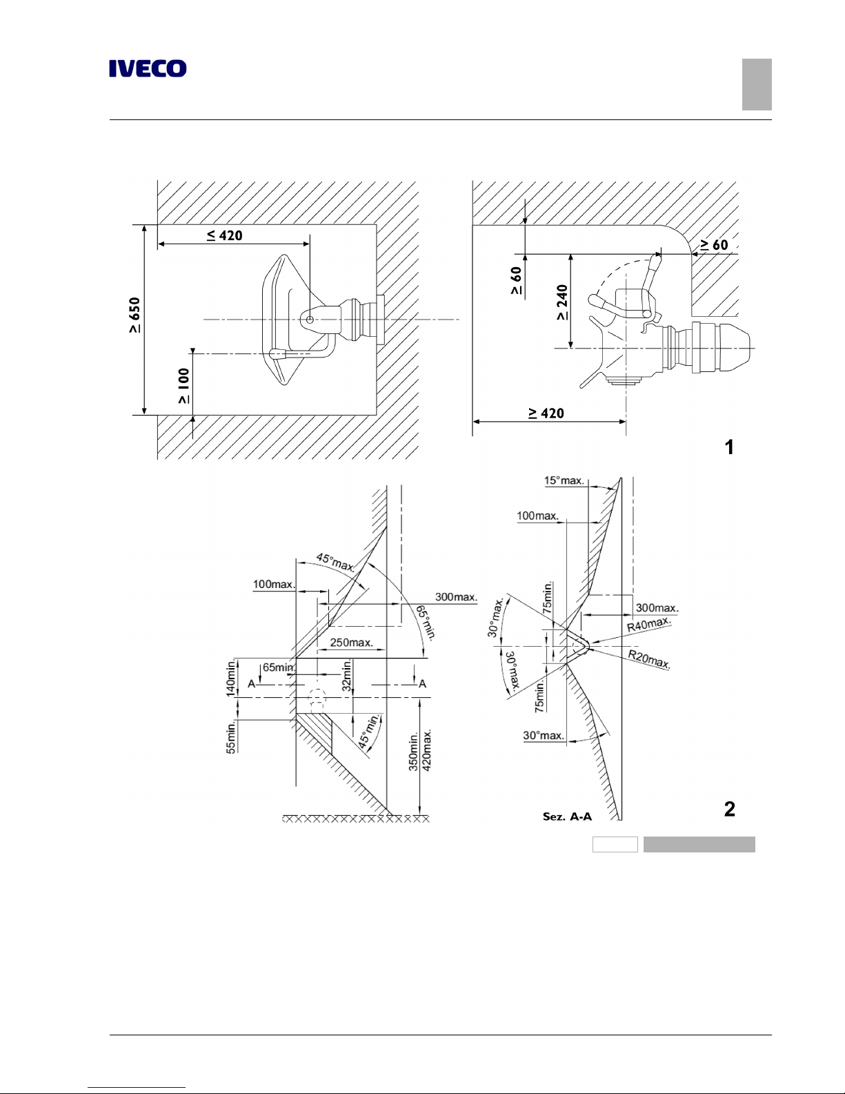
EUROCARGO Euro 6 – CHASSIS INTERVENTIONS
CHASSIS INTERVENTIONS
2.6 INSTALLING THE TOW HOOK
21
– Printed 603.95.747 – 1st Ed. - Base 12/2013
196787
Figure 9
1. Free field for towing hooks 2. Free field for coupling hooks according to standard DIN
74058 ESC-152
In cases where the connection flange of the drawbar coupling does not have holes suitable to those on the existing rear crossbar of
the vehicle, the latter may be authorised for modification upon application of adequate reinforcements.
The Bodybuilder has the duty of realising and installing the superstructure so as to allow coupling connection and checks without
impairment or hazard of sort.
The trailer drawbar must be guaranteed freedom of movement.
Page 50

22
EUROCARGO Euro 6 – CHASSIS INTERVENTIONS
CHASSIS INTERVENTIONS
2.6 INSTALLING THE TOW HOOK
– Printed 603.95.747 – 1st Ed. - Base 12/2013
Towing hooks for conventional trailers
According to Directive 94/20/CE, both for the choice of the hook and for the application of any reinforcements to the rear crossbar, it is important to take into account the action of the horizontal forces generated by the masses of the tractor and trailer, based
on the following formula:
D = 9.81 (T • R) / (T + R)
D = representative value of drawbar class [kN]
T = maximum mass of the tractor [t]
R = maximum mass of trailer with mobile vertical drawbar [t]
Drawbar couplings for centre axle trailers
Centre axle trailers are defined as those that have the drawbar rigidly connected to the frame and the axle (or more close axles)
placed at half the length of the same chassis.
Compared to the articulated drawbars, the rigid drawbar acts on the drawbar coupling with the increase of the static vertical loads
and, in the braking phase or in the oscillations caused by the road surface, the increase of the dynamic vertical loads. By means of
the hook, these loads lead to increases in the torsion of the rear crossbar of the vehicle, as well as push-ups on the overhang.
The use of centre axle trailers therefore requires the use of suitable towing hooks.
The values of the towed weights and vertical loads allowed are listed on the technical documents of the drawbar coupling manufacturer and on the part manufacture plate (see DIN 74051 and 74052).
Towing hooks that bear special approvals and with values greater than those listed in the above standards may be used. However,
these towing hooks may pose restrictions in relation to the type of trailer used (e.g. drawbar length); In addition, the drawbar may
require reinforcement for the towing vehicle as well as larger counter chassis profile section.
For mechanical coupling devices for trailers with a central axle, refer to the following formulas:
DC= g (T • C) / (T + C)
V = a • C (X2/ L2)
DC= representative value of drawbar class [kN]. This is defined as the determination of the theoretical reference value for horizontal load between tractor
g = acceleration of gravity [m/s2]
T = maximum weight of tractor
R = maximum weight of trailer
S = value of vertical static load that, in static conditions, is transmitted to the coupling point. S must be ≤ 0.1 x R ≤ 1000 kg of the
trailer
C = sum of maximum axial loads of the centre axle trailer at full load It is equal to the maximum mass of the trailer decreased by
the vertical static load (C = R - S)
V = value of the theoretical dynamic vertical load [kN]
a = vertical acceleration in the area of the drawbar coupling/hook. in function of the rear tractor suspension, use the following
values:
● a = 1.8 m/s2of air suspension
● a = 2.4 m/s2for other types of suspension
X = length of the load bed [m], (see Figure 2.10)
L = theoretical drawbar length, distance between the centre of the drawbar eye and the centre line of the trailer axles [m], (see
Figure 2.10)
X2/ L2≥ 1 if the result is less than the unit, use the value 1
Page 51
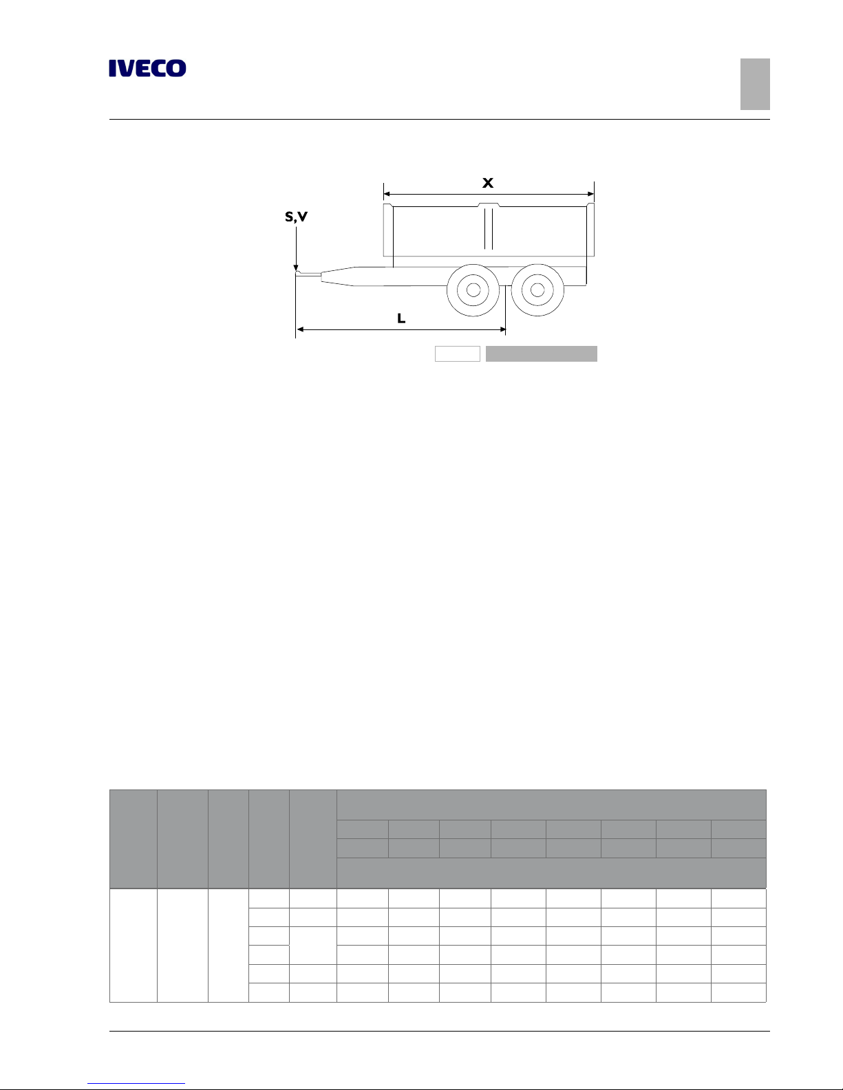
EUROCARGO Euro 6 – CHASSIS INTERVENTIONS
CHASSIS INTERVENTIONS
2.6 INSTALLING THE TOW HOOK
23
– Printed 603.95.747 – 1st Ed. - Base 12/2013
193864
Figure 10
X. Length of the trailer load bed L. Theoretical drawbar length
If you wish to use the tow with a vehicle not originally designed (and in compliance with the limits established by IVECO for each
model), only original rear crossbars which have already been hole punched can be mounted. Towable masses and the bearable
vertical loads can be defined based on the size of the hole.
To tow centre-axle trailers the vehicle must have an adequate connection between the chassis and the counter chassis and, in particular, in the area that goes from the rear end of the overhang to the front support of the rear suspension, longitudinal and transverse sealing plates need to be provided.
Moreover, in the case of long rear overhangs and depending on the masses to be towed, it may be necessary to adopt sections of
the counter chassis having a larger size than those normally provided.
Example of calculations for connection device class for centre axle trailers
We shall consider a vehicle with maximum weight of 18 t that must tow a centre axle trailer of 9 t with length of load bed 8 m and
theoretical drawbar length of 7 m.
The data at hand yields:
R = 9 t
S equals 0.9 t, i.e. the least of the values 0.1 • R = 0.9 t and 1 t
X2/ L2= 64 / 49 = 1.3
we obtain:
DC= 9.81 • [18 • (9 - 0.9)] / [18 + (9 - 0.9)] = 9.81 • (145.8 / 26.1) = 54.8 [kN]
V = 1.8 • (9 - 0.9) • 1.3 = 18.95 [kN]
Table 2.10 - Longitudinal sections of the counter chassis for centre axle trailers
Models
Profile
chassis
AxB
[mm]
S
[mm]
Wheel-
base
[mm]
Over-
hang
rear.
[mm]
R = Maximum weight of trailer [kg]
S = Vertical static load on the trailer hook [kg]
R≤4500 R≤6500 R≤9500 R≤10500 R≤12000 R≤14000 R≤16000 R≤18000
S≤ 450 S≤ 650 S≤ 950 S≤ 1000 S≤ 1000 S≤ 1000 S≤ 1000 S≤ 1000
Section modulus Wx[cm3] for longitudinal sections of the counter chassis
with yield point of the material equal to 360 N/mm
2
75E 172.5x65 4
2790 1313 16 16
3105 1313 16 16
3330
1830
16 25
3690 18 25
4185 2145 36 57
4455 2280 44 63
Page 52

24
EUROCARGO Euro 6 – CHASSIS INTERVENTIONS
CHASSIS INTERVENTIONS
2.6 INSTALLING THE TOW HOOK
– Printed 603.95.747 – 1st Ed. - Base 12/2013
Models
Profile
chassis
AxB
[mm]
S
[mm]
Wheel-
base
[mm]
Over-
hang
rear.
[mm]
R = Maximum weight of trailer [kg]
S = Vertical static load on the trailer hook [kg]
R≤4500 R≤6500 R≤9500 R≤10500 R≤12000 R≤14000 R≤16000 R≤18000
S≤ 450 S≤ 650 S≤ 950 S≤ 1000 S≤ 1000 S≤ 1000 S≤ 1000 S≤ 1000
Section modulus Wx[cm3] for longitudinal sections of the counter chassis
with yield point of the material equal to 360 N/mm
2
75E
172.5x65
5 4815 2505 39 63
75EP
4
2790 1313 25 39
3105 1313 33 44
3330
1830
57 70
3690 57 78
4185 2145 78 85
4455 2280 78 95
5 4815 2505 78 85
80E
195x65
4
3105 1313 16 16 16 16
3330
1830
16 16 34 34
3690 16 24 44 44
5
4185 2145 16 19 57 57
4455 2280 19 39 63 70
4815 2505 32 57 78 85
80EP
4
3105 1313 18 39 57
3330
1830
44 63 85
3690 63 78 100 100
5
4185 2145 57 78 100 100
4455 2280 78 85 100 112
4815 2505 78 100 120 120
90E
195x65
4
3105 1313 16 16 16
3330
1830
16 18 38
3690 16 25 49
5
4185 2145 18 36 50
4455 2280 18 44 70
4815 2505 44 63 85
90EP
4
3105 1313 16 49 63
3330
1830
63 78 95
3690 70 85 100
5
4185 2145 70 85 100
4455 2280 85 100 112
4815 2505 85 112 130
100E 195x65
4
2790 1313 16 16 16
3105 1313 16 16 16
3330
1830
16 29 44
3690 18 44 57
5
4185 2145 25 50 70
4455 2280 44 57 78
4815 2505 57 78 100
Page 53

EUROCARGO Euro 6 – CHASSIS INTERVENTIONS
CHASSIS INTERVENTIONS
2.6 INSTALLING THE TOW HOOK
25
– Printed 603.95.747 – 1st Ed. - Base 12/2013
Models
Profile
chassis
AxB
[mm]
S
[mm]
Wheel-
base
[mm]
Over-
hang
rear.
[mm]
R = Maximum weight of trailer [kg]
S = Vertical static load on the trailer hook [kg]
R≤4500 R≤6500 R≤9500 R≤10500 R≤12000 R≤14000 R≤16000 R≤18000
S≤ 450 S≤ 650 S≤ 950 S≤ 1000 S≤ 1000 S≤ 1000 S≤ 1000 S≤ 1000
Section modulus Wx[cm3] for longitudinal sections of the counter chassis
with yield point of the material equal to 360 N/mm
2
100EP 195x65
4
2790 1313 63 70 78
3105 1313 49 57 70
3330
1830
70 85 100
3690 85 100 112
5
4185 2145 85 100 125
4455 2280 100 100 130
4815 2505 100 124 135
120E
240x70
5
3105 1313 16 16 16 16 16 16
3690 1740 16 16 16 16 16 16
4185 2055 16 16 40 45 45 45
6
4455 2190 16 16 16 16 16 16
4815 2460 18 25 63 63 63 63
6.7
5175 2685 18 21 63
5670 3000 29 63 100
6570 3500 85 112 135
120EP
5
3105 1313 16 16 16 16 16 16
3690 1740 39 63 85 85 85 85
4185 2055 70 85 115 115 115 115
6
4455 2190 44 70 100 100 100 100
4815 2460 70 100 130 130 130 130
6.7
5175 2685 70 100 130
5670 3000 112 130 150
6570 3500 135 170 210
140E
240x70
5
3105 1313 16 16 16 16
3690 1740 16 16 16 16
4185 2055 20 44 49 49
6
4455 2190 18 29 44 44
4815 2460 44 78 78 78
6.7
5175 2685 63 85 85 85
5670 3000 85 130 130 130
6570 3605 133 170 170 170
140EP
5
3105 1313 16 29 44 44
3690 1740 63 85 85 85
4185 2055 100 130 130 13
6
4455 2190 100 130 130 130
4815 2460 130 150 150 150
6.7
5175 2685 130 150 150 150
5670 3000 150 190 190 190
6570 3605 190 215 230 230
Page 54

26
EUROCARGO Euro 6 – CHASSIS INTERVENTIONS
CHASSIS INTERVENTIONS
2.6 INSTALLING THE TOW HOOK
– Printed 603.95.747 – 1st Ed. - Base 12/2013
Models
Profile
chassis
AxB
[mm]
S
[mm]
Wheel-
base
[mm]
Over-
hang
rear.
[mm]
R = Maximum weight of trailer [kg]
S = Vertical static load on the trailer hook [kg]
R≤4500 R≤6500 R≤9500 R≤10500 R≤12000 R≤14000 R≤16000 R≤18000
S≤ 450 S≤ 650 S≤ 950 S≤ 1000 S≤ 1000 S≤ 1000 S≤ 1000 S≤ 1000
Section modulus Wx[cm3] for longitudinal sections of the counter chassis
with yield point of the material equal to 360 N/mm
2
150E
240x70
5 3105 1313 16 16 16 16
6
3690 1740 16 16 16 16
4185 2055 16 25 35 35
4455 2190 16 50 57 57
6.7
4815 2460 29 78 78 78
5175 2685 78 100 100 100
7.7
5670 3000 78 115 115 115
6570 3605 130 150 170 170
150EP
5 3105 1313 16 16 16 16
6
3690 1740 35 57 57 57
4185 2055 85 100 100 100
4455 2190 100 125 125 125
6.7
4815 2460 100 135 135 135
5175 2685 130 150 150 150
7.7
5670 3000 130 170 170 170
6570 2605 170 230 230 230
160E
240x70
5 3105 1313 16 16 16 16
6
3690 1740 16 16 16 16
4185 2055 16 16 16 16
4455 2190 16 25 35 35
6.7
4815 2460 25 57 57 57
5175 2685 57 85 85 85
7.7
5670 3000 78 115 115 115
6570 3605 130 183 183 183
160EP
5 3105 1313 16 16 16 16
6
3690 1740 16 25 35 35
4185 2055 70 85 85 85
4455 2190 85 100 100 100
6.7
4815 2460 85 130 130 130
5175 2685 130 150 150 150
7.7
5670 3000 130 183 183 183
6570 3605 172 230 230 230
180E
262.5x80
(in line
217.5x80)
6 3690 1133 16 16 16 16
7.7
4185 1313 16 16 16 16
4590 1650 16 16 16 16
4815 1853 16 16 16 18
5175 2123 16 16 16 57
5670 2235 18 35 35 78
6210 2235 16 16 16 63
Page 55

EUROCARGO Euro 6 – CHASSIS INTERVENTIONS
CHASSIS INTERVENTIONS
2.6 INSTALLING THE TOW HOOK
27
– Printed 603.95.747 – 1st Ed. - Base 12/2013
Models
Profile
chassis
AxB
[mm]
S
[mm]
Wheel-
base
[mm]
Over-
hang
rear.
[mm]
R = Maximum weight of trailer [kg]
S = Vertical static load on the trailer hook [kg]
R≤4500 R≤6500 R≤9500 R≤10500 R≤12000 R≤14000 R≤16000 R≤18000
S≤ 450 S≤ 650 S≤ 950 S≤ 1000 S≤ 1000 S≤ 1000 S≤ 1000 S≤ 1000
Section modulus Wx[cm3] for longitudinal sections of the counter chassis
with yield point of the material equal to 360 N/mm
2
180E
262.5x80
(in line
217.5x80)
7.7 6590 2775 78 100 100 150
180EP
6 3690 1133 16 16 16 16
7.7
4185 1313 16 16 16 16
4590 1650 16 18 18 63
4815 1853 18 35 49 110
5175 2123 49 78 78 133
5670 2235 78 100 100 133
6210 2235 57 85 85 115
6590 2775 130 150 150 211
190E
262.5x80
(in line
217.5x80)
6 3690 1133 16 16 16 16
7.7
4185 1313 16 16 16 16
4590 1650 16 16 16 16
4815 1853 16 16 16 18
5175 2123 18 35 35 57
5670 2235 18 49 57 78
6210 2235 18 35 35 63
6590 2775 85 115 115 150
190EP
6 3690 1133 16 16 16 16
7.7
4185 1313 16 16 16 16
4590 1650 16 35 35 63
4815 1853 49 78 78 110
5175 2123 85 115 115 133
5670 2235 85 115 115 133
6210 2235 78 100 100 115
6590 2775 135 170 170 211
Note
See Table 3.2 (profile dimensions).
Page 56
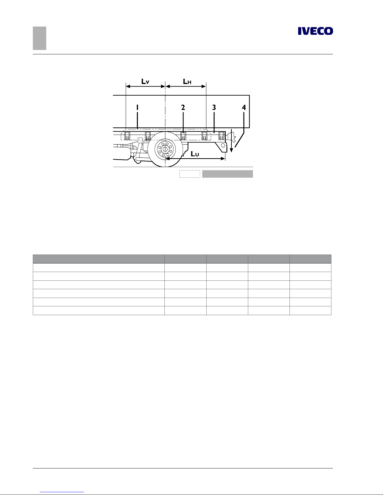
28
EUROCARGO Euro 6 – CHASSIS INTERVENTIONS
CHASSIS INTERVENTIONS
2.6 INSTALLING THE TOW HOOK
– Printed 603.95.747 – 1st Ed. - Base 12/2013
102183
Figure 11
LU = Rear overhang
LV = Length of the reinforcement parts placed in front of the
centre line of the rear axle
LH = Length of the reinforcement parts placed behind the
centre line of the rear axle
1. Combined reinforcement
2. Shear resistant connections
3. Longitudinal counter chassis section
4. Vertical static load on the towing hook
Use sections with a greater resistance modulus if the superstructure requires it. Check from time to time the need to install a suitable towing crossbeam and a suitable hook.
Table 2.11 - Solutions with combined reinforcement sections
A B C D
R
0.2
(N/mm2) (1) 320 320 360 360
Maximum reduction of the section height [mm] 40 60 100 120
LV(see figure 2.11) 0.5 L
U
0.5 L
U
0.8 L
U
0.85 L
U
LH(see figure 2.11) 0.6 L
U
0.6 L
U
0.95 L
U
1.0 L
U
Example of combined sections in alternative to C 250x80x8 [mm] 210x80x8 190x80x8 150x50x8 + angle 130x50x8 + angle
Actual reduction in height [mm] 40 52 92 104
The possibility of interrupting the combined reinforcement continuity is limited to special cases and must be authorized. Similarly,
when the application of the external reinforcement angle (solutions C and D see Figure 3.24), presents difficulties (e.g. presence of
suspension supports, or of the coupling brackets of the air spring) and the recess to perform could reduce excessive the resistance
capacity of the section, the solution must be submitted for approval with the proposed reinforcements.
Rear crossbar in lowered position
When the drawbar coupling must be lowered from its original position, IVECO may issue an authorisation to lower the original
drawbar or install an additional drawbar, which is the same as the original, in a lowered positioned.
Figures 2.12 and 2.13 show the respective realisation examples.
Connection of the drawbar in its new position must be performed in the same way and using screws of the same type (diameter
and resistance class) in relation to the original connection.
Anti-unscrewing systems must be used in the connections.
Page 57
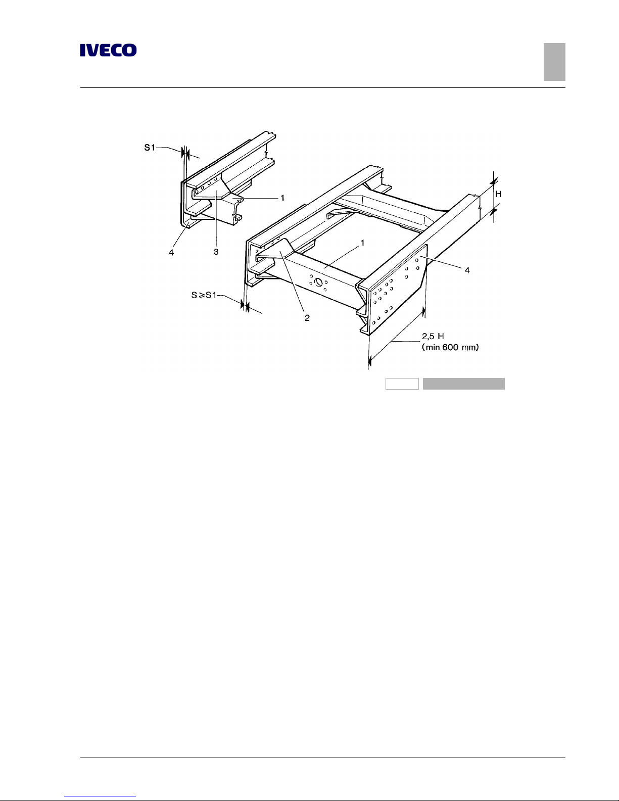
EUROCARGO Euro 6 – CHASSIS INTERVENTIONS
CHASSIS INTERVENTIONS
2.6 INSTALLING THE TOW HOOK
29
– Printed 603.95.747 – 1st Ed. - Base 12/2013
192343
Figure 12
1. Original rear cross member.
2. Gusset plate
3. Overturned gusset plate
4. Connecting corner
The outer corners should have a thickness of not less than that of the side members of the vehicle, they should extend in length
for a distance of at least 2.5 times the height of the side member itself (min 600 mm) and should use a material with the minimum
requirements set out in Chapter 3.3 - Paragraph "Choosing the type of connection" ( ➠ Page 11). The fastening to the vertical rib
of the side members must be done with all the union screws of the crossbar to the chassis of the vehicle, integrating them with
others whose number and positioning consider the greater time transmitted. In principle, in the lowerings equivalent to the height
of the side member, an increase in the number of screws equal to about 40% is predicted.
In applying a supplementary crossbar (see Figure 2.13) a central coupling plate must be provided, of thickness suited to that of the
crossbars.
Page 58
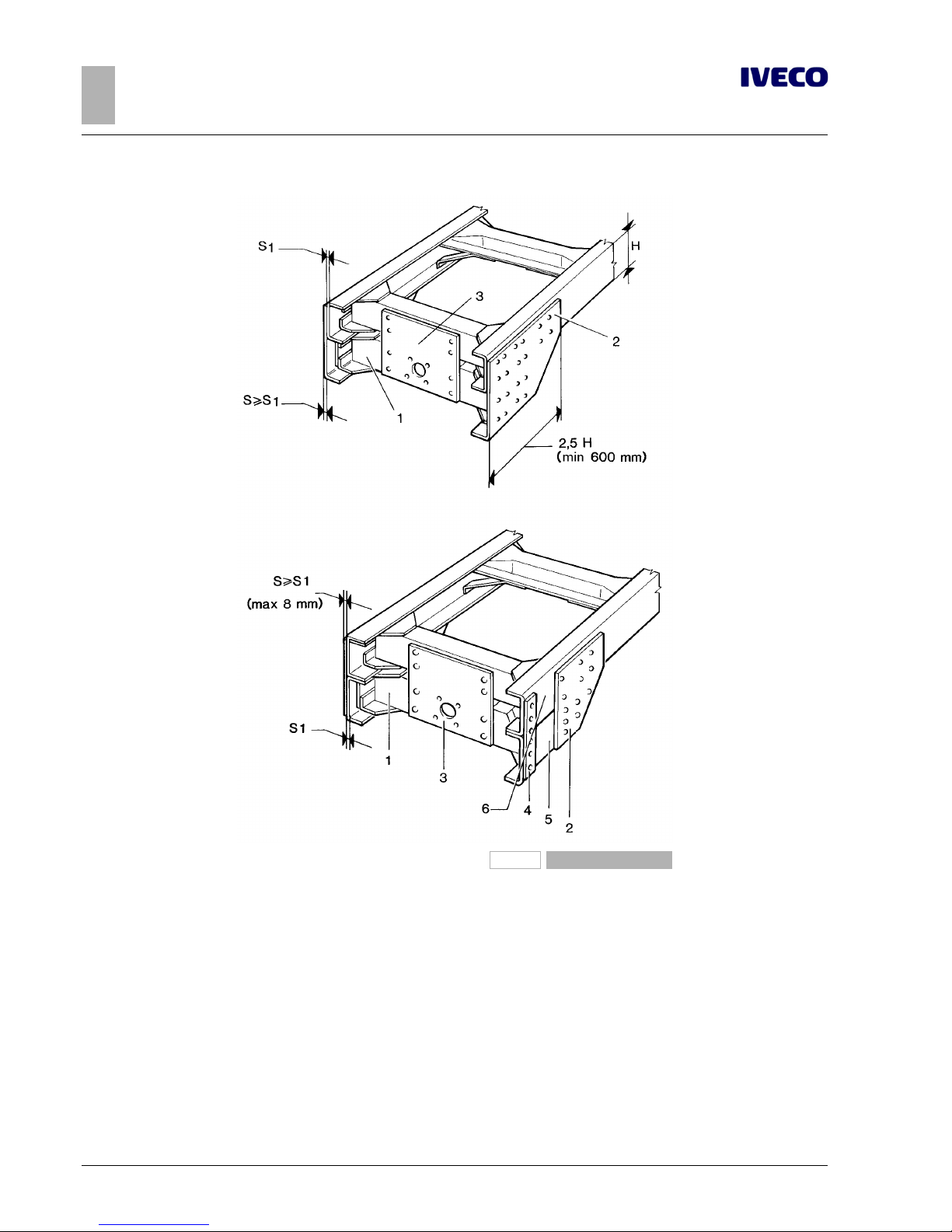
30
EUROCARGO Euro 6 – CHASSIS INTERVENTIONS
CHASSIS INTERVENTIONS
2.6 INSTALLING THE TOW HOOK
– Printed 603.95.747 – 1st Ed. - Base 12/2013
192344
Figure 13
1. Original rear cross member.
2. Connecting plate or angle
3. Coupling plate
4. Connecting plate
5. C-profile (same dimensions as chassis)
6. Space for rear spring retainer
The movements between the drawbar and the vehicle established by regulations in force must be ensured.
If the local legal regulations provide it, after construction the vehicle must be presented for the required checks.
Figure 2.13 shows an example of a lowered supplementary crossbar.
In cases where this solution is chosen on vehicles with short rear overhangs, the external connection angle must be made according
to the solution proposed therein. If, after lowering the rear crossbar, the shelves of the guards need to be changed, there must
be a method of fastening, resistance and rigidity equivalent to the original. Verify compliance with the standards for positioning the
lights.
Page 59
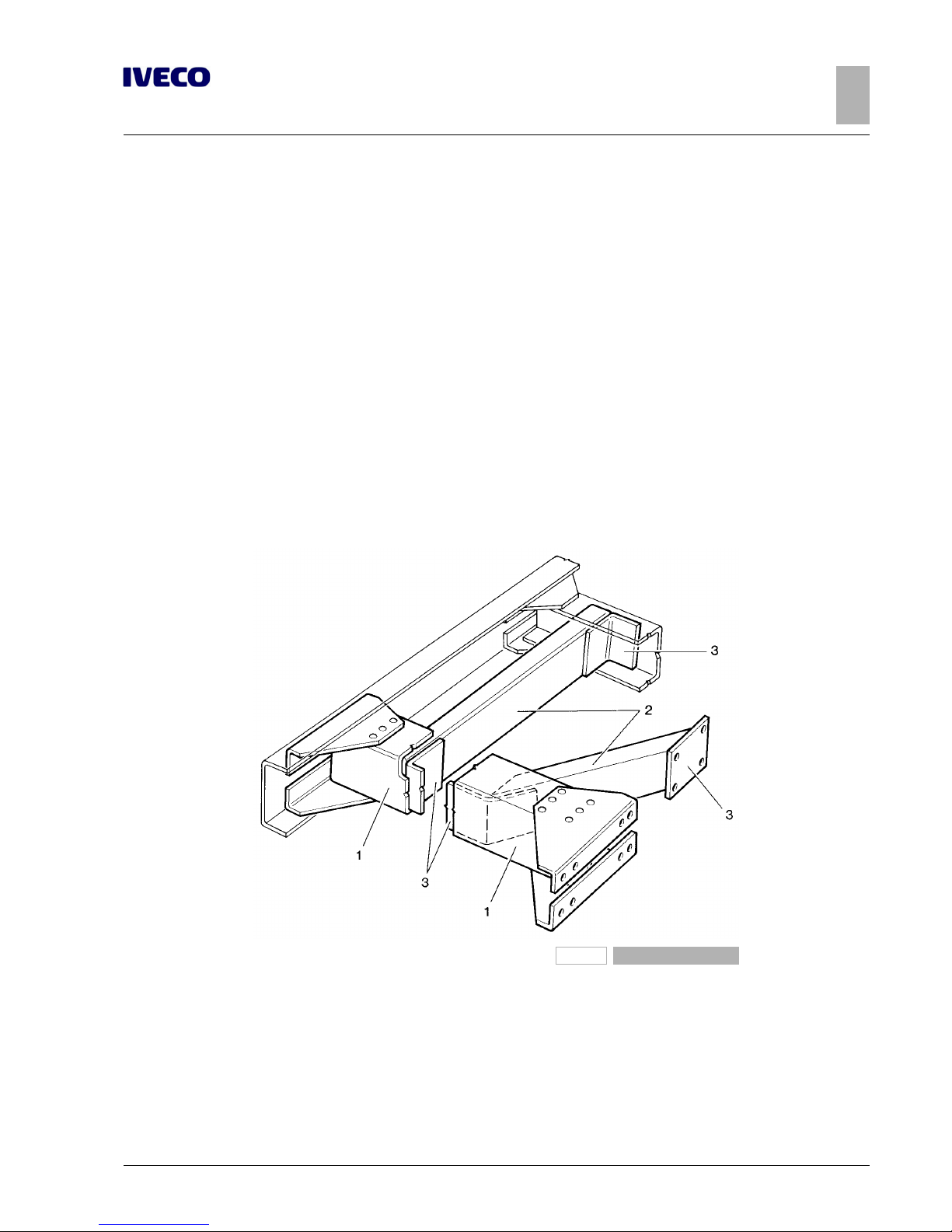
EUROCARGO Euro 6 – CHASSIS INTERVENTIONS
CHASSIS INTERVENTIONS
2.6 INSTALLING THE TOW HOOK
31
– Printed 603.95.747 – 1st Ed. - Base 12/2013
Tow beam in a lowered and forward position (close coupling) for centre axle trailers
Vehicles that, to tow centre axle trailers, must adopt a two beam in a lowered and forward position (close to the rear housings of
the rear suspension or air springs), do not require special chassis reinforcement.
The Bodybuilder must provide an adequate two beam and use a suitable drawbar coupling.
The positioning of the hook must be made in order to allow all relative movement between the tractor and the trailer drawbar in
the various conditions of use, subject to the necessary safety margins and compliance with any regulations or legal requirements.
Since in these cases the normal version of the under-run protection bar can not be used, the Bodybuilder will be responsible for
investigations on possible exceptions permitted or to be taken on the specific solutions (e.g.. tilting bumper beam).
Standard crossbar reinforcements
In cases where it is necessary to reinforce the standard crossbar and there are no originally reinforced crossbars, you will have to
resort to the application of:
● C-profile within the crossbar an adequate reinforcement even of the connections of the same to the side members of the
vehicle;
● C profile within the crossbar with connection to the vertical rib of the side member or to the next crossbar of the chassis if it
is located in close proximity, according to Figure 2.14;
91459
Figure 14
1. Original rear cross member.
2. Reinforcing profile
3. Connecting plates or angles
● suitably sized box-shaped crossbar, fastened on the ends to the vertical rib of the side members and connected to the cross-
bar in the central part, as shown in Figure 2.15. In vehicles with short rear overhang and in the presence of the subframe, the
box profile can be inserted inside the profiles of the counter chassis, above the crossbar and connected to it by means of a
front plate (as in Figure 2.13).
If in the mounting of the box profile it is necessary to operate on the brackets of the under-run protection bar, there must be
a version equivalent to the original in terms of fastening, resistance and rigidity (respect any national legal requirements).
Page 60
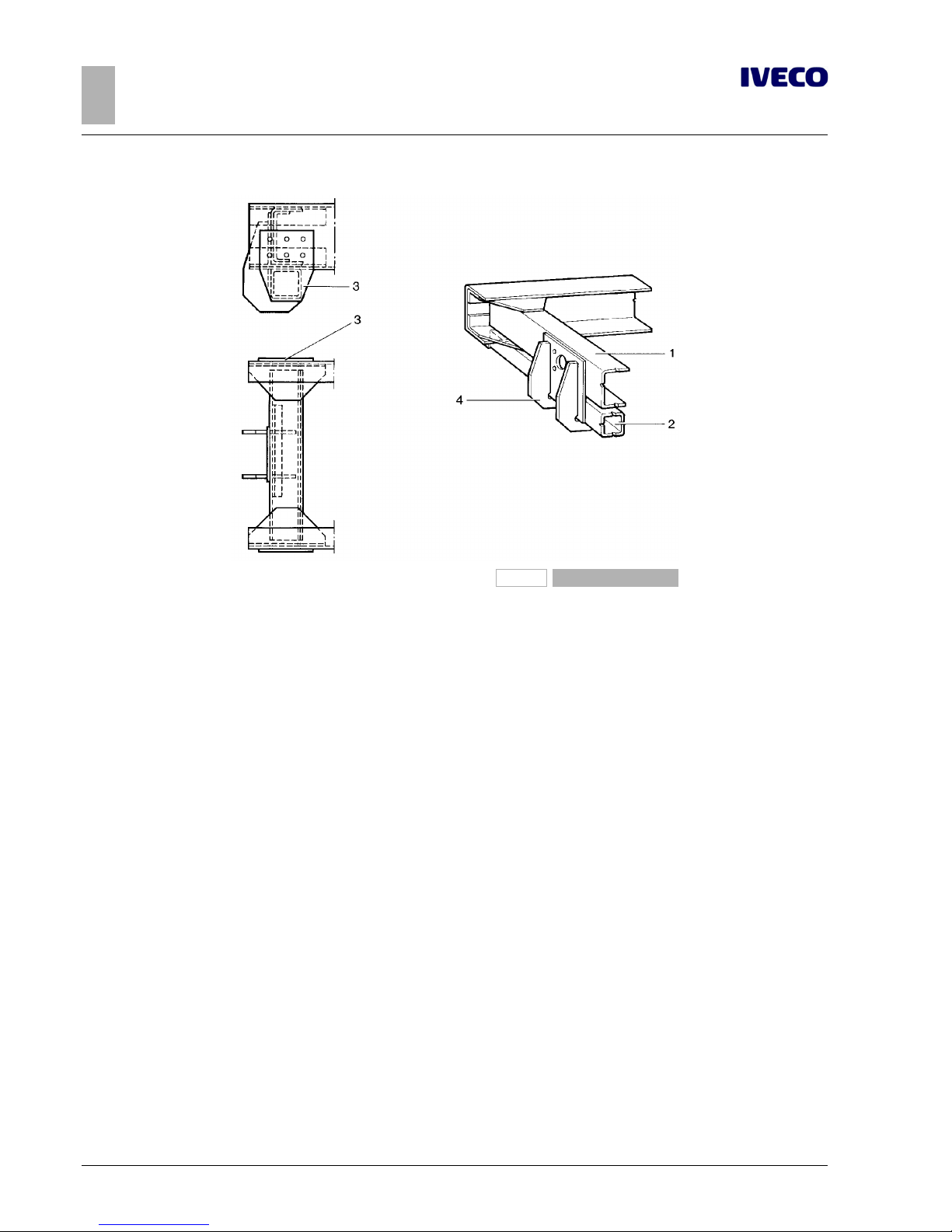
32
EUROCARGO Euro 6 – CHASSIS INTERVENTIONS
CHASSIS INTERVENTIONS
2.6 INSTALLING THE TOW HOOK
– Printed 603.95.747 – 1st Ed. - Base 12/2013
91460
Figure 15
1. Original rear cross member.
2. Box profile
3. Connecting plate
4. Coupling plate
Observations on payload
Static load on the drawbar coupling must not surpass the load allowed on the rear axle or axles of the vehicle. Furthermore, the
minimum front axle load must be respected as indicated in Chapter 1.15 ( ➠ Page 11).
Increase of tow weight
As regards tow vehicles, IVECO may evaluate - in certain cases and for particular applications - the possibility to authorise greater
tow weights than those normally allowed.
These authorisations include the towing conditions and, when necessary, provide the instructions relevant to any vehicle modifications or work required: standard crossbar reinforcements (see Figure 2.13), or installation of a reinforced crossbar when available,
or adjustments to the braking system.
The drawbar coupling must be suited for the new use, and its connection flange must coincide with that of the crossbar.
Fix the crossbar to the chassis by using flanged head screws and nuts or hex head screws of 8.8 min. class.
Use anti-unscrewing systems.
Plates
Some countries require a plate to be applied on the towing device, which must list maximum tow load and maximum vertical load
allowed.
If not already mounted, the Bodybuilder shall see to its manufacture and installation.
Page 61
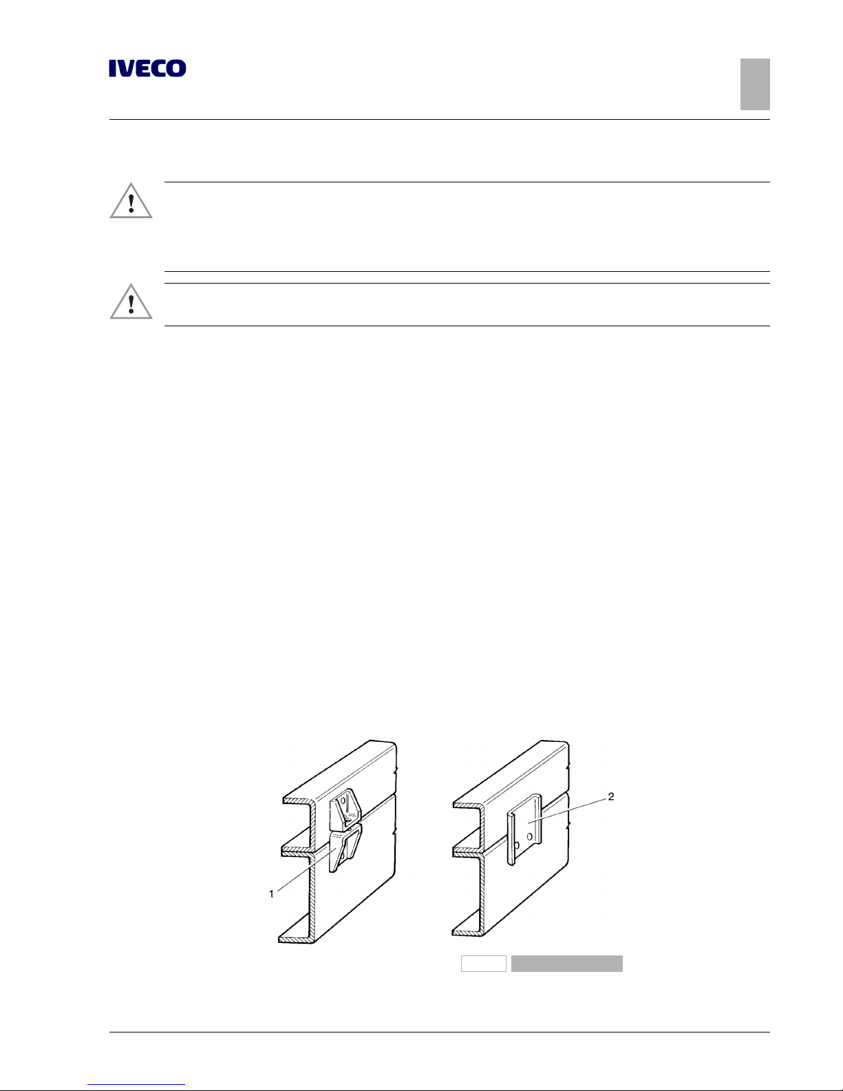
EUROCARGO Euro 6 – CHASSIS INTERVENTIONS
CHASSIS INTERVENTIONS
2.7 ASSEMBLING AN ADDITIONAL AXLE
33
– Printed 603.95.747 – 1st Ed. - Base 12/2013
2.7 ASSEMBLING AN ADDITIONAL AXLE
▶ The installation of an additional axle includes the perfect integration with the braking system,
pneumatic system, wiring and electronic systems: therefore approval by IVECO is necessary.
The request of technical information at the axle manufacturer and suppliers of plants and systems involved in the transformation is the responsibility of the bodybuilder, as well as performing the functional and approval tests.
▶ The granting of the authorisation to install an additional axle and the passing of the approval
tests do not exempt the Bodybuilder from full responsibility for processing.
General information
On some models of the EuroCargo range, it may be possible to apply an additional axle and consequently increase the gross vehicle
weight.
For its implementation, the mass limits and conditions imposed by IVECO must be respected, as well as all other conditions requested by national laws and the necessity to ensure driving safety and proper vehicle function.
This includes the need to verify, due to the GVW increase, the adequacy of the FUP (Front Underrun Protection) and RUP
(Rear Underrun Protection) type to the new situation and their possible replacement (see chapter 2.20 ( ➠ Page 58) and 2.25
( ➠ Page 61)).
Any application diagrams sent to IVECO - Technical Application to be examined and authorised must show indications regarding
connection of the axle to the chassis, as well as information on reinforcement and on changes to be made on the chassis; diagrams
regarding modifications to systems must also be provided.
With regard to modifications to the chassis, in addition to complying with the indications in the previous paragraphs, it is necessary
to consider the increase in stress due to the increase in the permitted load and the different conditions of operating dynamic stress.
The transformed frame must, in the corresponding sections, not be subjected to bending loads no greater than on the frame of the
original vehicle.
Reinforcements on the chassis
Figure 2.16 shows several examples of possible solutions.
The reinforcements must concern the entire length of the chassis, up to the cab.
192346
Figure 16
1. Bracket 2. Plate
Page 62
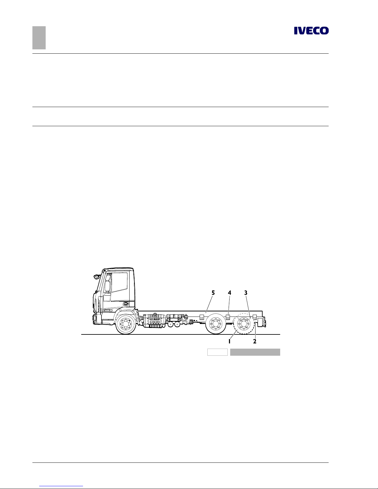
34
EUROCARGO Euro 6 – CHASSIS INTERVENTIONS
CHASSIS INTERVENTIONS
2.7 ASSEMBLING AN ADDITIONAL AXLE
– Printed 603.95.747 – 1st Ed. - Base 12/2013
In the case of a counter chassis reinforcement, the anchors provided on the chassis may be used (if in existence), otherwise they
should be made according to the indications in Chapter 3.1 - Paragraph "Sizing of profiles" and subsequent paragraphs.
We recommend creating a cut-resistant joint in the area of the rear overhang and for about half of the wheelbase length (and
always for lengths of at least 2 m from the front axle) (see Figure 2.16).
Note
Reinforcement plates may not be mounted directly onto the side member flaps via holes filled with welding material; Negative
effects on the strength of the original sections, due to incorrect welding, should be avoided.
Added axle
For the installation of a rear or central third axle the following changes are mandatory:
● use of suitable brake cylinders on the axle for the parking brake;
● adjustment of the brake system.
It is necessary that, of the two ABS solenoid valves on the axle, one handles the right wheels of the engine axle and of the added
axle and the other one the left wheels.
a) rear
The installation of an axle behind the engine axle generally results in the lengthening of the chassis overhang (see Figure 2.17), to be
realised according to the indications in Paragraph "Lengthening" ( ➠ Page 18) and without prejudice to the need for reinforcements
as referred to in Paragraph "Reinforcements on the chassis" ( ➠ Page 33).
For vehicles with a tapered frame, the adaptation of the section of the new overhang to the rest of the sections of the chassis can
be a useful solution for containment of the stresses caused by transformation.
196781
Figure 17
1. Added supplementary axle
2. Lengthening of the overhang
3. Reinforcements for modification of the chassis
4. Connections
5. Reinforcing profile
Page 63
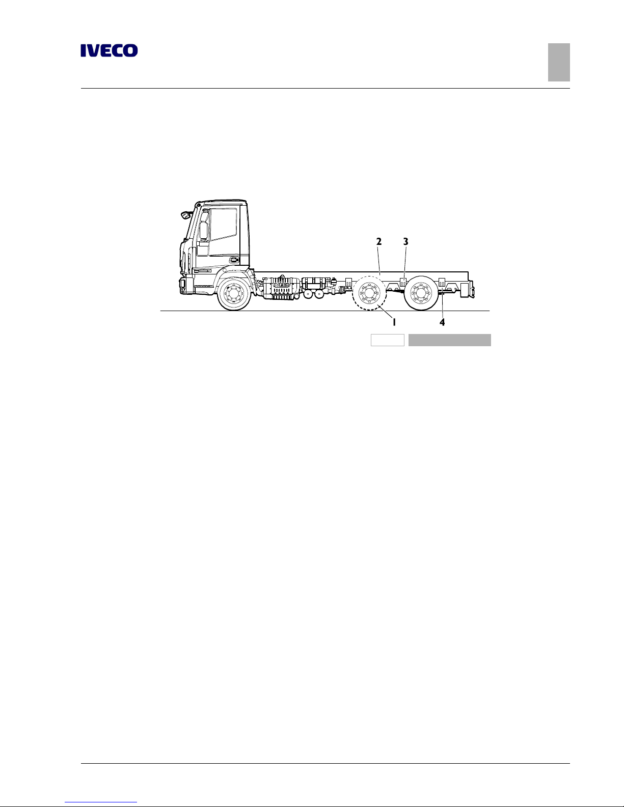
EUROCARGO Euro 6 – CHASSIS INTERVENTIONS
CHASSIS INTERVENTIONS
2.7 ASSEMBLING AN ADDITIONAL AXLE
35
– Printed 603.95.747 – 1st Ed. - Base 12/2013
b) central
The installation of an axle in front of the engine axle may make it necessary to reduce the rear overhang (see Figure 2.18), to be
realised according to the indications in Paragraph "Shortening" ( ➠ Page 18) to respect the technically permissible load.
Special attention must be paid to avoiding possible interference between the added axle and the drive shaft.
196782
Figure 18
1. Added supplementary axle
2. Reinforcing profile
3. Connections
4. Shortening (if necessary) of the rear overhang
Steering axles
Steering axles can be installed in both the centre position and the rear position and be either the self-steering or controlled steering
type; they must be built and installed in order to ensure the necessary safety for functionality and driving.
● Self-steering axles must be equipped with a device that keeps them in place while reversing, which can be activated from the
driver's seat.
● The application of a controlled steering axle, obtained through the original device of the vehicle's steering system, requires
authorisation from IVECO upon presentation of the supplementary system diagram.
Suspension
The construction quality of all the components must be ensured (axle, suspension, brake assemblies, systems etc.) in order to guarantee the driving safety and the correct functioning of the vehicle.
Particular attention must be paid to the realization of the suspension, given its importance in the vehicle's road handling.
The type of suspension to be realized may be mechanical leaf spring, air spring or mixed; its execution must not compromise the
vehicle's handling or its components in terms of driving stability, comfort, cornering performance and transmission working angle
(with the relative space restrictions in the event of an additional intermediate axle).
Implementation of a compensated type suspension is recommended (particularly for off-road vehicles), both total and partial, to
maintain constant the load distribution on two rear axles and to ensure that both axles are in condition to react to static and dynamic loads established in the original design, and in conditions imposed by the relevant Standards (e.g. difference in axle levels).
If there is a suspension independent of that of the engine axle, in principle rigidity characteristics can be adopted, proportional to
those of the original rear suspension, in the ratio of the static loads on the two axles.
Page 64

36
EUROCARGO Euro 6 – CHASSIS INTERVENTIONS
CHASSIS INTERVENTIONS
2.7 ASSEMBLING AN ADDITIONAL AXLE
– Printed 603.95.747 – 1st Ed. - Base 12/2013
Parabolic suspension
Interventions are generally not allowed on this type of suspension.
Exception is made for outfits or special uses for which, in order to increase suspension rigidity, the application of rubber elastic
elements may be authorised.
In special cases and only after IVECO approval, the addition of supplemental sheets on the parabolic springs may be allowed; this
must be carried out by a specialised spring manufacturer.
Transformation of the suspension from mechanical to pneumatic (for the shop van fitting)
This type of transformation is strongly discouraged because it involves the suspension components and chassis coupling elements
essential for the active safety of vehicle.
The bodybuilder that intents to perform the intervention must present a detailed documentation to IVECO in order to obtain a
technical approval.
In case of installation of not original components, it is noted that any approval is issued on the basis of a specially planned evaluation
of their characteristics and without the contribution of specific tests, unlike when use of components of first use.
Therefore, for this particular type of transformation, IVECO shall be relieved from any liability that may be attributed to the new
component.
Stabiliser bars
In the case of an additional axle with air suspension, it might be necessary, depending on the solution adopted, to provide a stabiliser
bar, particularly when there is a superstructure with high centre of gravity.
Similar stability measures should be adopted for mixed suspensions on added rear axles.
Attachments to the chassis
The connections for the added axle to the chassis must be able to react directly on all the longitudinal and transversal forces
without transmitting them to the engine axle.
In the points of application of forces (spring supports, brackets for air springs, etc.), suitable crossbars or adequate reinforcements
to the chassis must be provided.
It is important to remember to create the correct orthogonality and alignment of the added axle, respectively, with the longitudinal
axle of the vehicle and with the drive wheel axle.
Check the special equipment available on the market.
Brake system
▶ Considering the importance for the active safety of the vehicle, extreme care must be given to
the braking system in both design and implementation.
The same type of braking units, pipes and couplings as on the original vehicle must be used on the added axle; in particular, the
braking unit must be of the type that equips the front axle.
For connection between the fixed parts (chassis) and the axle, it is advisable to use flexible pipes.
Direct connection is allowed between the braking section of the added axle and that of the engine axle.
Verify that the capacity of the air tank is suitable to the dimensions of the new added brake cylinders and, if necessary, mount an
additional air tank.
We recommend activating the parting brake on the added axle as well.
Keeping in mind the different gross vehicle mass determined with the intervention, the braking torque must be adjusted to the new
static and dynamic loads in order achieve even distribution of braking among the axles.
Page 65

EUROCARGO Euro 6 – CHASSIS INTERVENTIONS
CHASSIS INTERVENTIONS
2.8 GEARBOX MODIFICATION
37
– Printed 603.95.747 – 1st Ed. - Base 12/2013
The total braking capacity of the modified vehicle must be proportional to that of the original vehicle and the performance of the
system (service, emergency and parking) must continue in any case to comply with national standards.
Note
After processing, the vehicle must be presented to the competent authorities for approval verifications (an individual test or approval of that type).
The documentation on the braking to be presented to the approval body (e.g. curves of adhesion and compatibility, distribution,
decelerations, heat behaviour, response time, etc.) must be provided by the person carrying out the work or the Manufacturer or
the added axle.
Technical documentation with the features of the system and the braking capacities of the original vehicle is available on request.
▶ For general indications on the braking system, follow what is set forth in Chapter 2.15.
▶ With regard to the electrical system, follow the indications in Chapter 5.7.
Lifting device
The added axle may be equipped with a lifting device and may be used, in special cases and if national laws allow it, for the purpose
of increasing grip of the engine axle in specific situations (starting on hills, slippery, snowy or icy roads).
For the device in question, the following conditions must exist:
● implementation depends on issuance by IVECO of the relative permit, on which the maximum permissible load on the over-
loaded axle is indicated;
● the use is limited to short sections of the route and the speed limit set in the specific authorisation.
Some national laws allow the use of the lifting device even in normal driving conditions, as long as the max approved load set for
the engine axle and the allowed speed limit are not exceeded.
In this case it is a good idea to remember the indications in Chapter 1.15 ( ➠ Page 11) with regard to the positioning of the centre
of gravity of the superstructure plus payload.
Note
After processing, the vehicle must be presented to the competent authorities for approval verifications (an individual test or approval of that type).
For service and maintenance operations on the added groups, use operating modes and intervention times consistent with the
provisions set for the original vehicle and shown on its documentation.
2.8 GEARBOX MODIFICATION
Gearbox adjustment, following wheelbase modification, must be done using the gearbox diagram of a similar range vehicle having
almost the same wheelbase.
The maximum tilt values of the drive shaft for the vehicle series must be respected, even for interventions on the rear engine axle
suspensions.
Contact the IVECO Technical Application for any difficulties; and send them a diagram with the length and tilt of the new transmission for a constant-velocity check.
The technical specifications in the gearbox Manufacturer manual must be used for correct production and installation of the sections.
Page 66
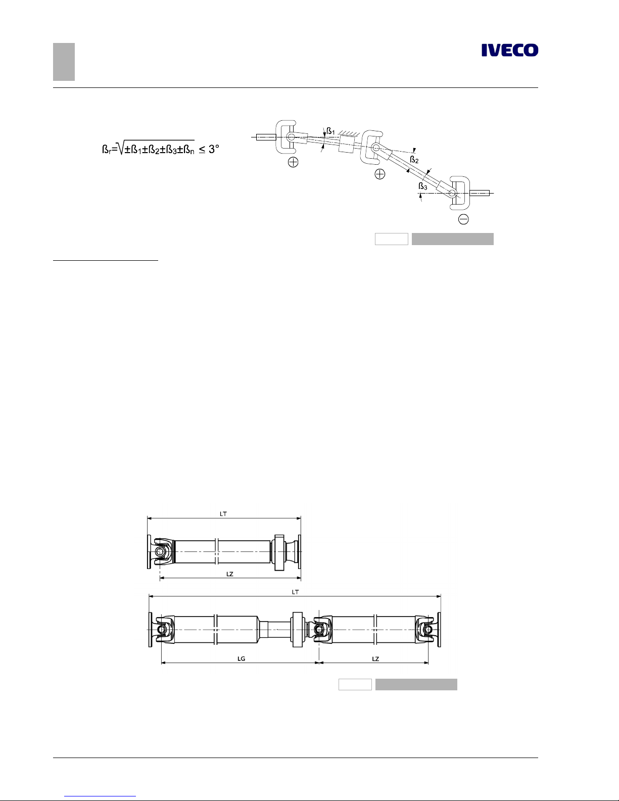
38
EUROCARGO Euro 6 – CHASSIS INTERVENTIONS
CHASSIS INTERVENTIONS
2.8 GEARBOX MODIFICATION
– Printed 603.95.747 – 1st Ed. - Base 12/2013
196780
Figure 19
Maximum allowed angularity
n = engine speed
β • n < 20000 for classes 2040-2045-2050
β • n < 25000 for classes 2025-2030-2035
Values that must be valid both when the vehicle is empty (tare only) and when the vehicle has a static load considering the maximum allowed load on the rear axle.
The scope of these instructions is to safeguard proper operation of the gearbox, limit sound level and avoid stress transmitted by
the drive assembly. In no way does this relieve the Outfitter of any work related liabilities.
Lengths allowed
1. The maximum work lengths that can be produced, both for the middle and sliding sections “LG” or “LZ” (see Figure 2.20),
can be determined in relation to the external diameter of the existing vehicle pipe and the maximum running rpm (see formula and Table 2.12).
If the shaft length calculated in this fashion is insufficient for the modification at hand, it is necessary to insert a new section
with the same characteristics as those mounted.
2. In some cases, a drive shaft with a larger diameter can be used and calculated (again, see Table 2.12) in relation to the length
required and the maximum number of engine rpm.
192345
Figure 20
LG Length of intermediate sections
LZ Length of sliding sections
LT Total length
Page 67

EUROCARGO Euro 6 – CHASSIS INTERVENTIONS
CHASSIS INTERVENTIONS
2.8 GEARBOX MODIFICATION
39
– Printed 603.95.747 – 1st Ed. - Base 12/2013
For sliding shafts, the length LG must be evaluated between the universal joint centres and with the sliding stem in the intermediate
position. Always check both stems LG and LZ.
The maximum number of engine rpm must be calculated with the following formula:
nG= n
max
/ (iG+ iV)
n
G
maximum engine speed [rpm]
n
max
engine speed [rpm] at maximum output power, see Table 2-12
i
G
gear ratio at highest speed, see Table 2-12
i
V
minimum transfer box ratio, 0.95 for EuroCargo 4x4 and equal to 1 if missing or for shafts upstream of the transfer box
Table 2.12 - Engine speed [rpm] at maximum output power and gear ratio
Engine Power [HP] n
MAX
[rpm] Gearbox i
G
4 cylinders
F4AFE411A 160 2500
5S -42 0.77
6S700 0.79
6AS700 0.79
F4AFE411B 190 2500
6S700 0.79
6AS700 0.79
S1000 0.71
S2500 0.74
F4AFE411C 210 2500
5S -42 0.77
6S800 0.78
6AS800 0.78
9S -75 0.73
S1000 0.71
S2500 0.74
6 cylinders
F4AFE611A 220 2500
6S800 0.78
6AS800 0.78
9S -75 0.73
12AS1210 0.813
S2500 0.74
S3000 0.73
F4AFE611E 250 2500
6S800 0.78
6AS800 0.78
9S -75 0.73
12AS1210 0.813
S3000 0.73
F4AFE611C 280 2500
6S1000 0.78
6AS1000 0.78
9S1110 0.78
12AS1210 0.813
S3000 0.73
F4AFE611D 320 2500
9S1110 0.78
12AS1210 0.813
S3000 0.73
Page 68
40
EUROCARGO Euro 6 – CHASSIS INTERVENTIONS
CHASSIS INTERVENTIONS
2.8 GEARBOX MODIFICATION
– Printed 603.95.747 – 1st Ed. - Base 12/2013
Note
Usually, the fork universal joints of the same shaft must not be rotated.
Pipe thickness
Valid tube thickness is usually not possible.
In fact, pipe thickness depends on the torque that the original shaft must transmit, as well as on the specifications of the transmission line (torque, power train ratio, axle loads or drive axles).
If using a pipe with a greater diameter than the original, thickness should in theory be reduced until reaching the same torsional
capacity; nevertheless, the dimensions of the fork male-end, need for adaptor rings, and the dimensions of pipes on the market
must also be taken into account.
Hence, the pipe thickness must be established on a case to case basis in relation to the dimensions of the driver shaft (e.g. cardan
joint size), in concert with the drive shaft Manufacturer authorised shops.
Minimum operating length (from flange to flange) must be at least 800 mm for sliding shafts and 700 mm for intermediate shafts.
Table 2.13 - Maximum possible lengths
Dimensions
of the
hook
outer diameter
x thickness
[mm]
Maximum propeller shaft speed [rpm]
2500 2700 2900 3300 3800
Maximum possible lengths LG to LZ [mm]
2030 90 x 3 2060 1960 1900 1760 1635
2035 100 x 3 2170 2100 2000 1850 1710
2040 120 x 3 2420 2350 2220 2070 1850
2045 120 x 4 2420 2360 2220 2070 1900
▶ The maximum lengths obtainable that are indicated above refer to original shafts; plan for
shorter lengths (-10%) for sections obtained after machining.
Positioning the sections
The transmissions that comprise several sections, each axle must be of approximately the same length. Generally speaking, the
distance between an intermediate shaft and sliding shaft (see Figure 2.21) must be no greater than 600 mm, while between two
intermediate shafts this difference must not be greater than 400 mm. As regards sliding shafts, there must be a minimum margin of
25 mm between minimum operating length and maximum sealing length; in opening, a covering must be guaranteed between the
shaft and the sleeve of approx. 2 times the diameter of the spline shaft.
Page 69
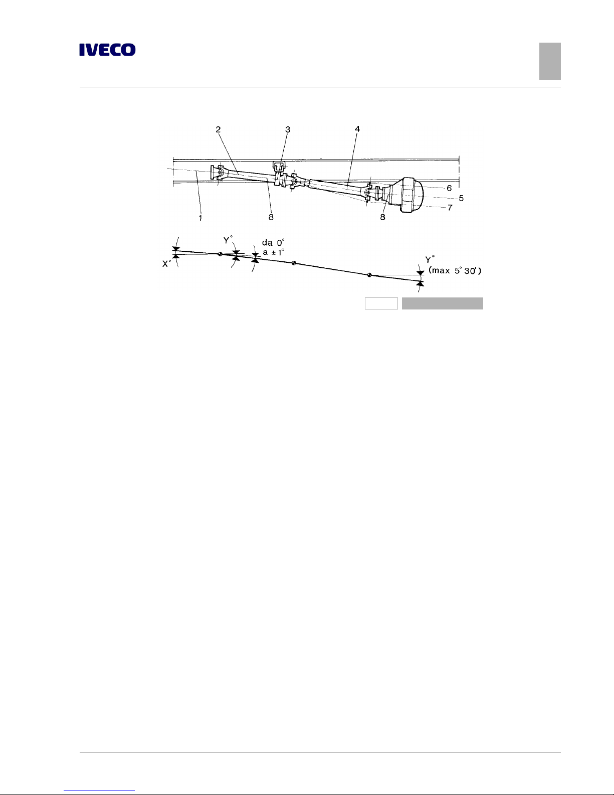
EUROCARGO Euro 6 – CHASSIS INTERVENTIONS
CHASSIS INTERVENTIONS
2.8 GEARBOX MODIFICATION
41
– Printed 603.95.747 – 1st Ed. - Base 12/2013
91451
Figure 21
1. Drive shaft, clutch, gearbox
2. Intermediate shaft
3. Intermediate shaft bearing
4. Sliding shaft
5. Rear axle casing tilt (static load)
6. Rear axle casing tilt (max compression)
7. Rear axle casing tilt (no load)
8. Intermediate shaft, sliding articulated shaft and rear axle
casing axis must have the same tilt.
The intermediate shaft and the axle casing axle must be aligned.
Their tilt may vary up to 1° in regards to that of the engine-clutch-gearbox axle; which may be obtained by placing a wedge
between the axle casing and the spring, or by means of adjusting the rear axle reaction bars.
The inclination of the rear axle casing must be no more than 5.5° from the horizontal plane.
When in vehicle loading conditions, the flange of the rear axle is lower than that of the gearbox housing flange, it is necessary to
make the inclination of the rear axle housing and the intermediate shaft greater than that of the engine-gearbox axle. Vice versa,
when in vehicle loading conditions, if the flange of the rear axle is higher than that of the gearbox housing flange, it is necessary to
make the incline of the axle housing and the intermediate shaft less than that of the engine-gearbox axle.
When wheelbase lengthening is substantial, it may be necessary to mount an additional intermediate section, as indicated in Figure
2.22. In this case, make sure that the engine-gearbox axle, the second intermediate shaft and the axle casing axis when in static load
are all aligned with the same tilt.
Page 70
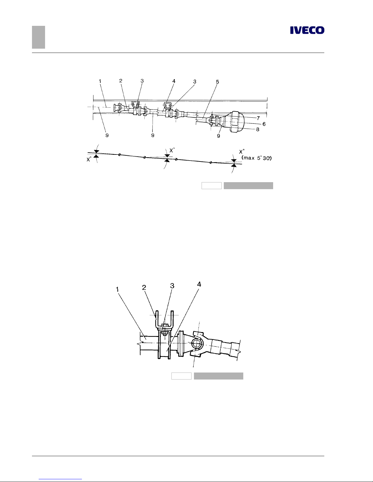
42
EUROCARGO Euro 6 – CHASSIS INTERVENTIONS
CHASSIS INTERVENTIONS
2.8 GEARBOX MODIFICATION
– Printed 603.95.747 – 1st Ed. - Base 12/2013
91452
Figure 22
1. Drive shaft, clutch, gearbox
2. First intermediate shaft
3. Intermediate shaft bearing
4. Second intermediate shaft
5. Sliding shaft
6. Rear axle casing tilt (static load)
7. Rear axle casing tilt (max compression)
8. Rear axle casing tilt (no load)
9. Gearbox, second intermediate shaft, sliding articulated
shaft and axle casing axis must have the same tilt.
The application of elastic bearings must be done using support plates at least 5 mm thick (see Figure 2.23), connected to crossbars
with characteristics similar to those specified by IVECO.
In modifying the wheelbase, it is best to plan for disassembly of intermediate shafts when shaft length is less than approximately 800
mm.
91453
Figure 23
1. Intermediate shaft
2. Support plate
3. Rest plate
4. Intermediate shaft bearing
The considerations made up to this point are valid for vehicles with separate gearboxes.
Furthermore, the wheelbase on these vehicles may not be reduced beyond the shortest value for the series (e.g. tipper truck).
We recommend using original IVECO gearboxes; if this is not possible, the use of raw steel pipes with a yield load of at least 420
N/mm2(42 kg/mm2) may be used.
Page 71

EUROCARGO Euro 6 – CHASSIS INTERVENTIONS
CHASSIS INTERVENTIONS
2.9 MODIFYING THE ENGINE AIR INTAKE AND EXHAUST SYSTEMS
43
– Printed 603.95.747 – 1st Ed. - Base 12/2013
The universal joints may not be modified.
For every transformation of the transmission, of any of its parts, a thorough dynamic balancing must be performed on each section
modified.
▶ Given that the transmission is an important part of the vehicle in terms on safety, we strongly
recommend that all modifications made to it stand up to maximum safety standards. Therefore,
all modifications should be made only by highly specialised Companies that are qualified by the
transmission Manufacturer.
2.9 MODIFYING THE ENGINE AIR INTAKE AND EXHAUST SYSTEMS
Note
The characteristics of the engine air intake and exhaust systems must not be modified. Modifications, if authorised by IVECO, must
not vary the original intake vacuum and exhaust counter-pressure values.
Table 2.14 - Maximum allowed counter-pressure at intake and exhaust under normal operating conditions and at full load
Engine Model Engine code
Exhaust
counter-pressure [kPa]
Intake vacuum [kPa]
TECTOR 4 CYLINDERS
F4AFE411A*C 15 4.3
F4AFE411B*C 15 4.3
F4AFE411C*C 15 4.3
TECTOR 6 CYLINDERS
F4AFE611A*C 26 5
F4AFE611E*C 26 5
F4AFE611C*C 26 5
F4AFE611D*C 26 5
Intake
The air intake must be mounted as to avoid intake of hot air from the engine compartment, or dust and water.
The intake compartment must be sealed airtight and fitted with rubber gaskets that prevent hot air recirculation. The gaskets must
be of high quality as to support a steady temperature of 100 ºC, with short durations of 120 ºC, without undergoing visible deformations or deteriorations. The compartment must keep airflow sections efficient for the entire circuit.
The holes that must be made in the box part of the van must have an area of about twice that of the cross-section of the pipe
upstream of the filter; these openings (e.g. grille holes) must have minimal dimensions to prevent possible clogging.
The following are not allowed:
● alterations or replacement of the original air filter with one of lower capacity;
● modifications to the silencer body;
● interventions on equipment (injection pump, control valve, injectors, etc.) that may compromise good engine performance
and affect exhaust gas emissions.
● change the succession Humidity sensor → Brakes air→ Blow by in the segment between air filter and turbine
Lastly, it is necessary to check if new system approval is required in relation to specific national standards (sound level, smokiness).
Page 72

44
EUROCARGO Euro 6 – CHASSIS INTERVENTIONS
CHASSIS INTERVENTIONS
2.10 MODIFYING THE ENGINE COOLING SYSTEM
– Printed 603.95.747 – 1st Ed. - Base 12/2013
Engine exhaust
Given the compaction of the “Hi-e SCR” system (see Section 6 ( ➠ Page 5)) and the optimal arrangement of its assemblies on
the chassis, any modifications to the exhaust pipe formation may be permitted only for the realization of a vertical exhaust outlet,
differing from that offered as optional 180.
The realization of a vertical exhaust requires the following:
● a considerable distance from the air intake conveyor;
● the simplest possible pipe route (curvatures with radii of no less than 2.5 times the outer diameter, passage sections no smal-
ler than those of the original solution, absence of throttling);
● suitable distances (min. 150 mm) from electrical systems and plastic pipes (shorter distances progressively require plate guards,
thermal insulators or the replacement of plastic pipes with steel ones);
● a support structure for the vertical part fastened to the vehicle chassis and braced, if necessary;
● a flexible pipe between the part of the exhaust connected to the engine and the part rigidly fastened to the chassis;
● a solution that prevents water entering from the top of the pipe (e.g. curvature).
2.10 MODIFYING THE ENGINE COOLING SYSTEM
The good operating conditions of the original system must not be altered, especially for what concerns the radiator, free surface of
the radiator and pipes (dimension and layout).
In any case, if modifications are required (e.g: cab modifications) that entail interventions on the engine cooling system, keep in mind
that:
● The air passageway area for radiator cooling must not be less than that on vehicles with series standard cabs;
● maximum air expulsion from the engine compartment must be guaranteed, making sure that there are no hot air pockets of
recirculation by adopting guards or deflectors;
● fan performance must not be modified;
● any modifications of the water piping must not compromise complete filling of the circuit (done with a steady flow and
without any backflow from the intake until the circuit is filled) and regular water flow; in addition, these modifications must not
alter maximum water stabilisation temperature, even in the most demanding conditions of use;
● pipe layout must be done so as to avoid the formation of air pockets (e.g. eliminating siphoning bends or installing required
vents) that may make water circulation difficult;
● check that water pump activation at engine start-up and successive operation during idling is immediate (accelerate a few
times), even when circuit is not pressurised. During checks make sure that the water pump supply pressure, with engine at
top speed and no load, is less than 1 bar.
To check the operation of the cooling circuit we must account for the water supply, bleed and circulation proceeding as follows:
● open the supply valve of the heating system and the heater bleed valves;
● fill the circuit while the engine is off with a flow rate of 8 - 10 l/min, until water seeps from the overflow vent;
● one bled, close the heater bleed valves;
● start the engine and run idle for 5 minutes, successively check to see that the water level in the supply tank has not dropped
below minimum level;
● gradually rev the engine, checking that average pressure in the water pump outlet pipes steadily increases without and discontinuities;
● keep accelerating the engine until the thermostat opens, causing air bubbles to pass through transparent pipes installed
between:
■ engine output and radiator;
■ water supply tank and water pump;
■ engine bleed and water supply tank;
● check, after the thermostat has be open for 15 minutes, that there are no more bubbles in the circuit;
Page 73

EUROCARGO Euro 6 – CHASSIS INTERVENTIONS
CHASSIS INTERVENTIONS
2.11 INSTALLING AN ADDITIONAL HEATING SYSTEM
45
– Printed 603.95.747 – 1st Ed. - Base 12/2013
● check that, with thermostat open and engine running idle, that average pressure in the water pump outlet pipe is greater than
500 mm water column.
2.11 INSTALLING AN ADDITIONAL HEATING SYSTEM
We recommend using IVECO type heating systems whenever it is necessary to install an additional heating system.
On vehicles where IVECO does not employ these heaters, installation must be done in compliance with the instructions issued by
the equipment Manufacturer (installation of heaters, pipes, electric system, etc.) and in relation to the following indications.
The additional heating system must respect all national standards on the subject (e.g. tests, specific installations for the transport of
hazardous materials, etc.). It must avoid the use of vehicle equipment that requires certified approval whenever such equipment
may cause a negative impact on performance.
In addition, be sure to:
● care for the proper operation of all other vehicle systems (e.g.: engine cooling system);
● check that the battery capacity and alternator power are sufficient for increased current draw (see Chapter 5.7 ( ➠ Page 36))
and install a protection fuse on the new circuit;
● connect - for the fuel supply - the supply system to a supplementary tank that is installed along the return pipe of the engine
fuel. Direct connection to the vehicle tank is allowed under the condition that it occurs independently from the engine fuel
supply, and the new circuit must be perfectly airtight;
● route piping and wiring layout (and installation of brackets and flexible fittings) in relation to the spaces available and the influ-
ence of heat on the chassis parts. Avoid any exposed parts that may be dangerous, and adopt suitable guards when necessary.
The system must allow easy access and prompt maintenance.
The Bodybuilder must provide all necessary maintenance instructions.
a) Water heaters
When the original vehicle heating and engine cooling circuits are involved (see Chapter 2.10 ( ➠ Page 44)), the following must be
done to ensure good system operation and safety of the original system:
● carefully define the connection points between the additional and original systems, in agreement with IVECO, if necessary.
The added pipes must be made of brass or other alloy resistant to the corrosive action of coolant, the coupling sleeves must
respect the requirements put forth by the standard IVECO 18-0400;
● plan for a rational layout of pipes, avoiding bottlenecks and siphoning bends;
● install venting valves (bleed points) to allow proper system filling;
● allow complete circuit discharge, also by installing any additional plugs;
● adopt, when necessary, suitable protections to limit heat loss.
b) Air heaters
As regards these heaters and for direct cab installation, be particularly cautious with the exhausts (to avoid combustion gasses from
being trapped in the vehicle) and correct distribution of hot air (in order to avoid direct flow).
Page 74

46
EUROCARGO Euro 6 – CHASSIS INTERVENTIONS
CHASSIS INTERVENTIONS
2.12 INSTALLING AN AIR CONDITIONING SYSTEM
– Printed 603.95.747 – 1st Ed. - Base 12/2013
2.12 INSTALLING AN AIR CONDITIONING SYSTEM
We recommend using original IVECO units for the installation of an air conditioning system.
When this is not possible, aside from complying with the specific requirements provided by the manufacturer of the equipment, it
is necessary to:
● maintain good performance of the vehicle parts that may be involved in the intervention;
● check that the battery capacity and alternator power are sufficient for increased current draw (see Chapter 5.7 - Paragraph
"Additional equipment" ( ➠ Page 43)) and install a protection fuse on the new circuit;
● plan the compressor installation modes with IVECO, if installed on the engine;
● route piping and wiring layout (and installation of brackets and flexible fittings) in relation to the spaces available and the influ-
ence of heat on the chassis parts;
● avoid layouts and installations where exposure may be dangerous when the vehicle is moving; fit suitable guards when necessary;
● the system must allow easy access and ensure prompt maintenance.
The Bodybuilder must provide all necessary maintenance instructions upon vehicle delivery.
In addition, in function of the type of system:
a) cab installed system:
● condenser installation must not cause negative effects on the engine cooling characteristics (reduction of exposed radiator-
engine area);
● condenser installation must not be coupled with the engine radiator, but placed in its own specific compartment with proper
ventilation;
● installation of the evaporator unit and of the bellow inside the cab (in cases where not provided directly from IVECO) must
be planned as not to negatively impact control functions and access to equipment;
b) cab roof-installed systems :
● it is necessary to verify that the mass of the equipment does not exceed the weight allowed by the cab; in addition, the Body-
builder must define the structural reinforcements to apply to the cab roof in relation to the unit's weight and type of intervention performed;
● contact IVECO or specific applications that involve an unoriginal compressor (e.g. fridge).
Note
Note that in relation to Directive 2006/40/EC on the emissions of air conditioning systems for motor vehicles, the use of fluorinated
GHG with overall heating potential over 150 in comparison to CO2 is prohibited.
2.13 WORK ON THE CAB
General information
All interventions on the steering cab must be authorised by IVECO in advance.
The modifications must not hinder operation of the control devices located in the area of the modification (e.g. pedals, switches,
pipes, etc.) nor alter the strength of load-bearing elements (frames, reinforcement profiles, etc.). Care must be taken when dealing
with operations that regard the engine cooling and air intake pipelines.
In relation to variation of cab weight, it is necessary to consider the position of the load in order to respect division of allowed axle
loads (see Chapter 1.15 ( ➠ Page 11)).
As regards operations that entail the removal of internal sound barriers or protective panels (panelling, cladding) be sure to remove only the minimum amount possible; restore the protections as intended in the original design along with their original functionality.
Cab installation of controls and equipment (PTO engage switch, external operator cylinder control, etc.) is allowed as long as:
Page 75

EUROCARGO Euro 6 – CHASSIS INTERVENTIONS
CHASSIS INTERVENTIONS
2.13 WORK ON THE CAB
47
– Printed 603.95.747 – 1st Ed. - Base 12/2013
● installation is rational, performed in good detail and easy to access by the driver;
● the proper safety, control and signalling devices called for by national law are installed.
Make sure that pipe and cable installation is performed properly also in function of cab tilting; adopt the necessary retainers and be
sure to plan for appropriate distances from the engine, heat sources and moving parts.
Each structural modification must bear protection against corrosion (see Chapter 2.3 ( ➠ Page 11)).
The use of zinc coated sheet metal is recommended on both ends of newly inserted sheet metal on cut bodywork in order to
avoid ferrous corrosion of the welds (I.S. 18-1317 class ZNT/F/10/2S or I.S. 18-1318 class ZNT/10/2S); both surfaces must undergo protective treatment.
Install gaskets with care and apply sealant to areas in need of protection.
Make sure that the seals are water, dust and smoke tight.
The Bodybuilder must check that the chassis, after its structural modifications, complies with the standards in force for what concerns both internal and external structure.
Work on the roof
Any cab modifications performed to create specific configurations must be done with care in order to protect the resistance and
maintain cab functionality and protections intact.
In any applications or units or equipment on the roof, make sure that the mass of the equipment does not exceed that permitted
by the cab. These limits can be provided on request, depending on the version.
Spoiler or top-sleeper installation
The installation must be performed by using the specially crafted fixing points on the cab roof sides and using support devices of
appropriate sizes.
If the national standards require it, these installations must be controlled by relevant authorities.
Realization of sleeper cabs
The transformation of the standard cab to a special cab or sleeper cab (special vehicles, public use, fire brigade, etc.) can be authorised by IVECO after the evaluation of the suitability of use of the suspension, tipping and locking systems to operate correctly even
under the new conditions.
In general solutions can be used that are equivalent to those provided by IVECO for the same applications.
To contribute to maintain the rigidity of the cab, it is recommended to keep the rear structure as much as possible unchanged.
It should be noted, however, that the transformation needs new approval tests (seats, seat belts, etc..) and that the relative costs
will be at total charge of the body builder.
The increase of the cab weight, requires appropriate interventions on the suspension, the tipping device and on the rear coupling;
the tipping angle must be reduced.
1. The definition of an appropriate suspension system requires:
■ respect the cab structure provided in the standard vehicle;
■ prevent that the added weight causes serious damage to the original parts of the cab and on the relative suspension parts;
■ ensure the normal oscillations along the vertical, longitudinal and transverse plane.
2. for the tipping it might be necessary to install a cylinder of higher capacity (with adequate supports) or an extra cylinder, verifying compliance with the minimum distances to the nearly arranged parts.
The areas affected by the thrust of such cylinders must be protected by an excessive concentration of stresses and therefore
must be provided:
■ the rear-most possible installation of the lifting points;
■ suitable coupling zones, both on the cab bottom and on the chassis.
Page 76

48
EUROCARGO Euro 6 – CHASSIS INTERVENTIONS
CHASSIS INTERVENTIONS
2.14 CHANGING TYRE SIZE
– Printed 603.95.747 – 1st Ed. - Base 12/2013
If during the tipping, the cabin exceeds the upper equilibrium point, make sure the added hydraulic system allows to keep
it in the limit switch position or otherwise, apply a safety rope.
3. The original coupling device includes a safety lock and an indicator that shows the successful activation: it is suggested to keep
this solution unchanged.
In case the transformed cab should not have the possibility of tipping, in addition to acting on the suspension as seen above, is necessary to provide a movable bonnet, hatches or panels for the inspection and maintenance of the underlying parts.
In order to facilitate interventions in the workshop it is recommended the installation of a rear coupling point for the lifting or the
possibility to apply safety bar.
In the change of the cab can be included the engine air intake and the filter. The use of original elements already provided for similar fittings, can be a good solution and allow the compliance with legislative regulations.
▶ Note that the cab transformation operations affect the good behaviour and the safety of the
vehicle (suspension, tipping manoeuvre) and therefore must be designed and carried out with
extreme care.
2.14 CHANGING TYRE SIZE
Note
Replacing the tyres with others of measure or load bearing capacity that differs from the specifications recorded at vehicle approval
require IVECO certification, as well as a test to determine whether the braking system requires adjustment.
The vehicle must successively be presented to the competent Body that will inspect the new tyres and the vehicle documents.
Mounting larger tyres:
● always requires a size check in relation to mechanical components, wheel arches, etc., in the various dynamic, steering and
vehicle shaking conditions;
● may entail rim replacement with the consequential need to verify the spare tyre holder modification;
● may affect distance from ground of the rear under-run protection device and, in this case, a check on standard compliance is
required; if necessary the support brackets must be replaced with appropriate and approved counterparts (see Chapter 2.20
( ➠ Page 58));
● requires the need to check compliance of the limit transverse contour allowed in relation to the various standards.
Prescriptions
Note
Replacing tyres with others of different external diameter affects vehicle performance (e.g.: speed, max. vehicle ramp slope, tow
load, braking force, etc.); therefore the IVECO Body Controller (speedometer, tachograph and speed limiter) must undergo recalibration at an authorised IVECO workshop.
▶ Tyres of different size and type of structure cannot be mounted on the same axle.
The tyre load bearing capacity and the relative reference speed must be suitable to the vehicle's performance.
Mounting tyres with lower load bearing capacity or reference speed entails a reduction of allowed loads; on the other hand,
mounting tyres with greater load bearing capacity does not automatically entail an increase of load allowed on the axles.
The dimensions and load bearing capacity of the tyres are established by international and national standards (ETRTO, DIN, CUNA,
etc.) and are listed in the manuals of their respective Manufacturers.
Particular performance values may be put forth by national standards for special uses, fire-protection, winter services, airport tank
trucks, buses, etc.
Page 77
EUROCARGO Euro 6 – CHASSIS INTERVENTIONS
CHASSIS INTERVENTIONS
2.15 WORK ON THE BRAKING SYSTEM
49
– Printed 603.95.747 – 1st Ed. - Base 12/2013
▶ If vehicle configuration requires the wheels to be removed, make sure that the contact surfaces
between rim and connection flange are clean and free of corrosion when remounting the wheels.
In addition, tighten the wheel studs at the tightening torque according to the IVECO standard
(see the following Table).
Table 2.15 - Wheel tightening torque according to IVECO STD 17-9219
CONNECTING ELEMENTS
Thread
TIGHTENING
CODE
Name CLASS
Torque [Nm]
FEATURES “S”
(*)
Min Max
1 Front and rear wheel mounting Nut M18x1.5 II 335 410 “S”
2 Front and rear wheel mounting Nut M20x1.5 II 540 440 “S”
3 Front and rear wheel mounting Nut M22x1.5 – 580 650 “S”
(*)
Characteristic “S”: safety tightening (see IVECO std. 19-0405).
▶ If using brackets to mount aesthetic studs positioned between the rim / lug or stud, or if using
rims thicker than the original, geometric mounting functionality must be ensured through appropriate lengths of stud threading in the locking hole.
2.15 WORK ON THE BRAKING SYSTEM
General information
▶ No changes are allowed to the regulating unit, distributor, brake cylinders, valves, etc., since
they are safety components.
▶ Any changes to the braking system (modification of pipes, installation of additional operating
cylinders etc.) requires the authorisation of IVECO.
Note
For new units, it is advisable to prefer the same brands as those fitted to the original vehicle.
If the national standards provide it, the vehicle must be presented to the competent authority for inspection.
In the case of displacement of control valves, dryer, etc., restore the same type of installation originally provided, ensuring the correct functionality; interventions on the dryer must also not affect the conditions of cooling air coming from the compressor.
Brake pipes
Note
In the case of changes to the wheelbase or the cantilever, the brake lines involved should preferably be replaced with new pipes
and in one piece; if this is not possible, the couplings to be used must be of the same type as the original ones.
▶ We would like to underline the dangers related to the full or partial painting of the pipes; there-
fore, during the intervention, the pipes must be properly masked.
When replacing, it is necessary to comply with the minimum internal dimensions of the existing pipes.
The characteristics and the material of the new pipes must match those originally used on the vehicle.
The installation must be carried out so that the system is adequately protected.
Page 78
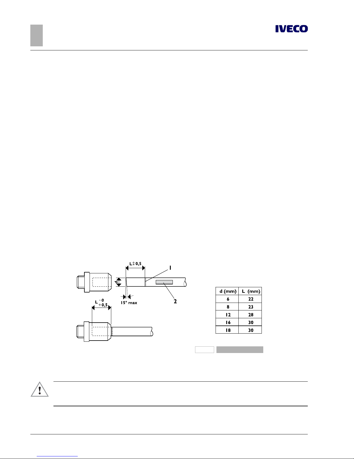
50
EUROCARGO Euro 6 – CHASSIS INTERVENTIONS
CHASSIS INTERVENTIONS
2.15 WORK ON THE BRAKING SYSTEM
– Printed 603.95.747 – 1st Ed. - Base 12/2013
For the supply of materials and their installation it is advisable to contact a Service Centre or Authorised Workshop.
Plastic pipes
In both the addition of new pipes and in the replacement of others, it should be noted that plastic material is not allowed:
● in areas where the internal/external temperature of the pipe may exceed 80 °C, (e.g. within 100 mm from the engine exhaust
outlet or section of pipe at a distance of less than 3 mm from the compressor outlet);
● between the chassis and moving parts, where special flexible pipes should be used;
● on hydraulic lines.
Operations must provide:
● materials and dimensions: Standard DIN 74324 (IVECO STD 18-0400) Maximum operating pressure 12.5 bar
● radii of curvature (referring to the centre line of the pipe):
■ Φ 6 to 35 mm
■ Φ 8 to 55 mm
■ Φ 12 to 85 mm
■ Φ 16 to 85 mm
Preparation and assembly (IVECO STD 17-2403)
Cut the pipe at right angles (15° maximum error), using a special tool in order to avoid imperfections that affect the sealing.
Permanently mark the section of pipe (dimension L in Figure 2.24) to be inserted into the coupling to ensure secure sealing.
Mark the pipe to avoid assembly errors in case of subsequent repair operations.
As much as possible, use the same couplings as the original ones, or otherwise belonging to the normal production of specialised
manufacturers in the sector.
193865
Figure 24
1. Identification of pipe limit 2. Marking
As much as possible, use quick-fit couplings.
▶ For each intervention on the piping, verify whether there is the need, depending on the supplier,
to use always new couplings or if it is possible to reuse those originally present through the use of
appropriate tools (pliers).
When the space conditions require it (e.g. in proximity of curves), couplings with metal inserts can be used.
Page 79
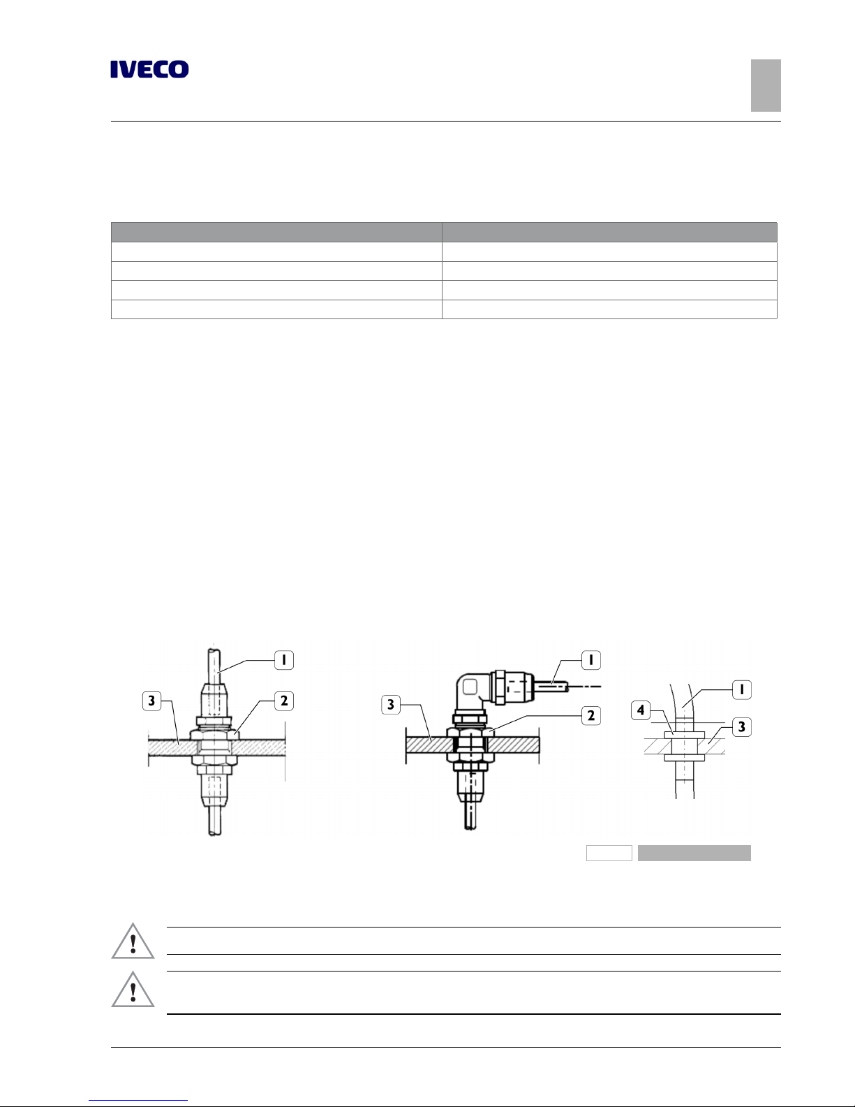
EUROCARGO Euro 6 – CHASSIS INTERVENTIONS
CHASSIS INTERVENTIONS
2.15 WORK ON THE BRAKING SYSTEM
51
– Printed 603.95.747 – 1st Ed. - Base 12/2013
Before inserting the pipe into the coupling, screw the coupling into the threaded insert of the same component (e.g. pneumatic
valve), using the following values for tightening:
Thread Tightening torque [Nm ± 10%]
M12 x 1.5 mm 20
M14 x 1.5 mm 24
M16 x 1.5 mm 30
M22 x 1.5 mm 34
Insert the pipe into the coupling for the previously marked stretch of length L, using a force of between 30 and 120 N, depending
on the size of the tube.
The replacement of components (valves, etc..) is made possible because the engagement and coupling allow an internal rotation
during the operation of unscrewing and screwing.
Vehicle pipe installation
Before use, the new pipes must be thoroughly cleaned inside, for example by blowing air with a compressor.
The pipes must be fixed to the frame with elements which envelop the pipe completely and which may be metal with
rubber/plastic protection or be made of plastic material.
Provide appropriate distances between one fastening element and the other: generally, max. 500 mm for plastic pipes and max.
600 mm for metal pipes can be considered.
In order to avoid deformations and tensions at the time of closure of the couplings for the plastic pipes, it is necessary to take care
of the line and the accommodation of the fastening elements, rubbing should be avoided with the fixed parts of the vehicle and
meet the necessary safety distances from moving parts and heat sources.
In passing the pipes through the chassis (side members or crossbars), take precautions to avoid damage. One solution would be to
use a coupling passing directly through or at an angle, or a rubber protective eyelet, as shown in Figure 2.25.
193866
Figure 25
1. Pipe
2. Through-coupling
3. Chassis
4. Rubber protection
▶ After each intervention is on the system or equipment, brake efficiency should be checked.
▶ Bring the pressure to its maximum level on the air system. Check for leaks in the areas affected
by the intervention.
Page 80

52
EUROCARGO Euro 6 – CHASSIS INTERVENTIONS
CHASSIS INTERVENTIONS
2.15 WORK ON THE BRAKING SYSTEM
– Printed 603.95.747 – 1st Ed. - Base 12/2013
193866
Figure 25
To ensure that the connections have been properly made, the air tank corresponding to an axle can be emptied; the pressure control on the in-vehicle indicator and the verification, by operating the brake pedal, on the remaining braking section(s), allow such
verification.
Hydraulic circuits must have the normal air bleed operation.
ABS electronic brake control devices
In case of changes to the wheelbase, the original position for ABS modulators must be maintained relative to the axis rear wheels.
The wiring between the sensors on the rear axle and the control unit, as well as between the control unit and the modulators,
must be adjusted using new cables or extension cables with appropriate connectors.
The brake piping upstream of the modulators must also be adequate.
Withdrawing air from the cooling system
In vehicles with a pneumatic brake system it is possible to withdraw a small amount of air from the tank in the auxiliary circuit. This
withdrawal should only occur through a limited return valve, which can avoid the lowering of the pressure below the threshold of
8.5 bar in the operating brake circuit and the auxiliary circuit.
Take the air directly from the 4-way safety valve (exit 24) of the braking system.
Page 81
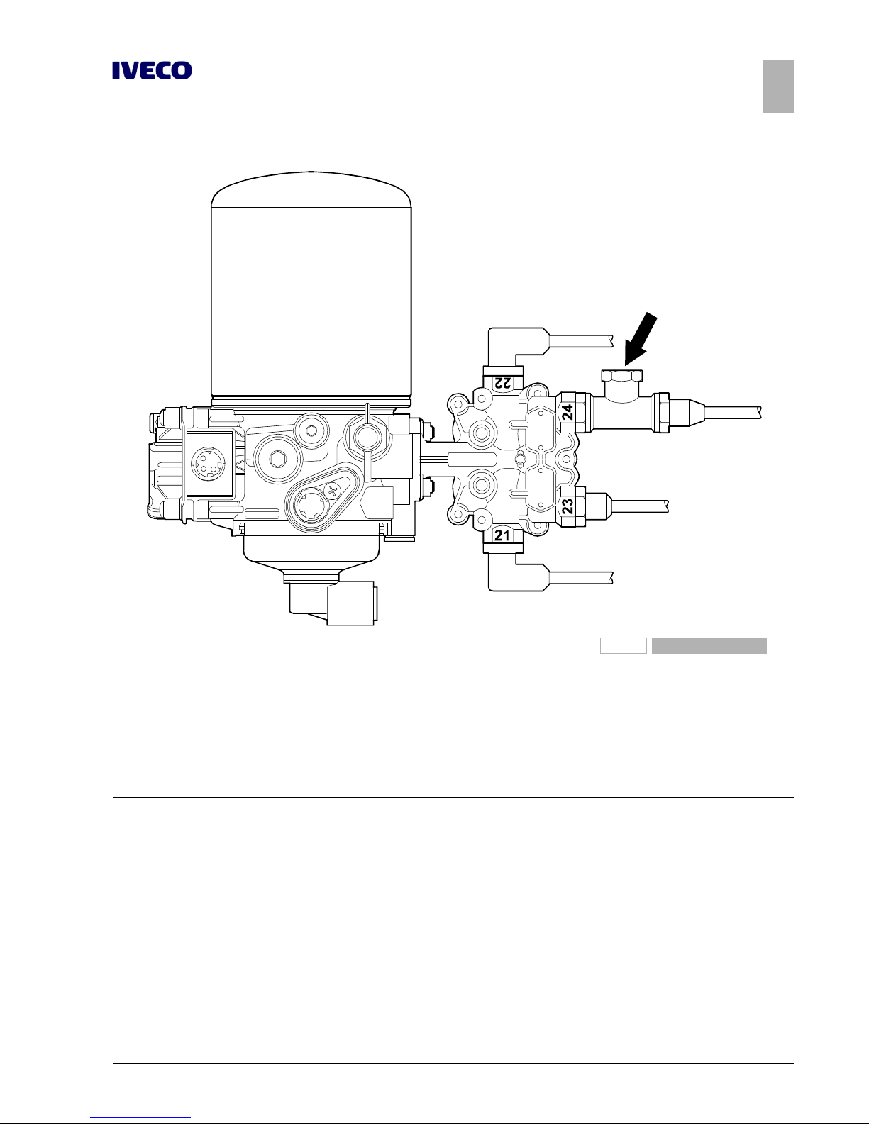
EUROCARGO Euro 6 – CHASSIS INTERVENTIONS
CHASSIS INTERVENTIONS
2.16 ELECTRICAL SYSTEM: CURRENT INTERVENTIONS AND DRAWS
53
– Printed 603.95.747 – 1st Ed. - Base 12/2013
196783
Figure 26
If you require larger quantities of air you have to assemble an additional tank.
In this case, however, it is necessary to ensure that the standard compressor is able to fill the tank within the specified time, otherwise you will need to install a higher capacity compressor.
If air tanks are added to the air suspension (connection 25, Air Drying Unit), the APU regeneration volume must be checked.
2.16 ELECTRICAL SYSTEM: CURRENT INTERVENTIONS AND DRAWS
Note
For information on work on the electrical system, refer to what is described in Section 5 - Chapter 5.7 ( ➠ Page 36).
2.17 PART RELOCATION AND ANCHORAGE OF ADDITIONAL UNITS AND EQUIPMENT
The movement of units (various components, fuel and urea tanks, batteries, spare wheel, etc.) for the installation of equipment is
allowed on the condition that:
● the functionality of the unit is not compromised;
● the original type of connection is restored;
● the new placement and distribution of mass is compatible with that originally established.
Horn
Page 82
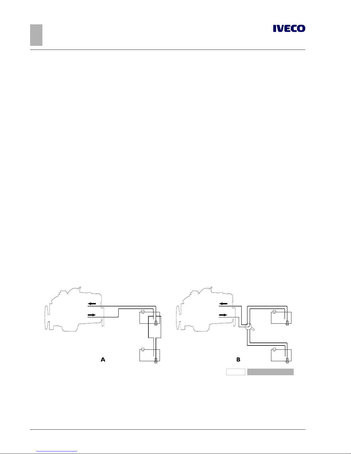
54
EUROCARGO Euro 6 – CHASSIS INTERVENTIONS
CHASSIS INTERVENTIONS
2.17 PART RELOCATION AND ANCHORAGE OF ADDITIONAL UNITS AND EQUIPMENT
– Printed 603.95.747 – 1st Ed. - Base 12/2013
The displacement of the horn obligates the body builder for a new approval. Also in the new position, the device must ensure the
acoustic performance set by the regulations and must be adequately protected from exposure of weathering and/or soiling. IVECO
reserves the right to void the warranty on the moved component.
Spare wheel holder
For chassis cabs not supplied with a spare wheel holder, or in cases where it is necessary to move the spare wheel, a special support must be made that allows rapid extraction and meets a minimum entry angle of 7°.
To secure the spare wheel with a support applied to the rib of the side member, we recommend the application of a local reinforcement plate arranged inside the side member itself and sized depending on both the mass of the wheel and the presence or
absence of other reinforcements on the side member.
To minimise torsional stress on the chassis of the vehicle it is advisable to perform the installation in correspondence with a crossbar, especially in the case of high mass units.
Similarly, it must act for the installation of tanks, compressors, etc.; the distribution of weight must also be taken into account for
their placement (see Chapter 1.15 ( ➠ Page 11)). Depending on the use of the vehicle, applications should always provide a sufficient margin in their height from the ground.
The holes to be drilled for the new arrangements should be made on the rib of the side member, according to the regulations
given in Chapter 2.2 ( ➠ Page 7) and taking care to use the existing holes as much as possible.
When filling the fuel tank is hindered by the superstructure, the tank support brackets can be placed lower down, with a displacement of a drilling module (45 mm).
Fuel tank
When it is necessary to increase the autonomy compared to the standard configuration, it is possible to:
● replace the tank with another of greater capacity, choosing from those provided in series;
● add an additional tank, chosen if possible from the standard ones and compatible with available space.
If the addition is made on the same side of the chassis, the two tanks can be connected with a flexible hose (at least in part) and fuel
can always be drawn from the original tank (Fig. 2.27 A).
When instead the additional tank is positioned on the opposite side of the chassis compared to the original, it is advisable to implement a scheme like the one in Figure 2.27 B, where the implementation of a diverter allows to alternatively use the two tanks.
196784
Figure 27
The chosen solution must be implemented in compliance with specific regulations.
The piping additions must ensure prefect sealing, have technical features and internal dimensions not less than those provided for in
the original system and be properly clamped.
Page 83
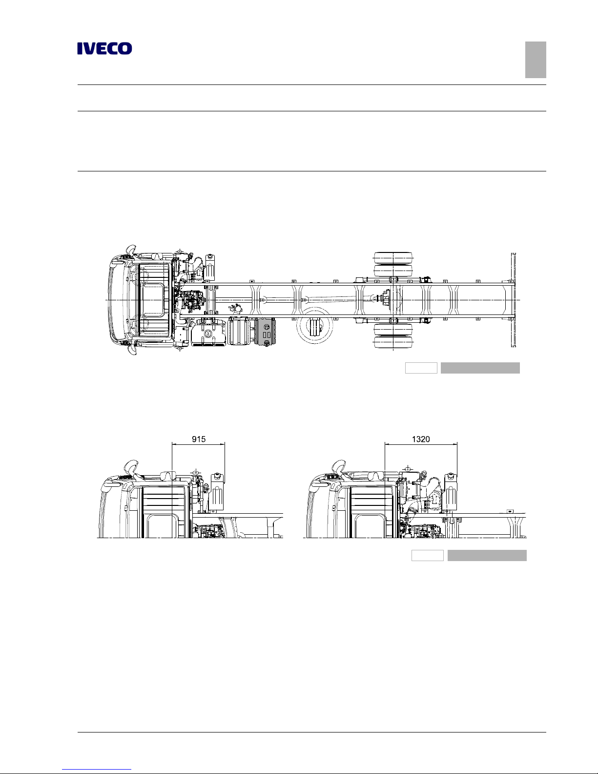
EUROCARGO Euro 6 – CHASSIS INTERVENTIONS
CHASSIS INTERVENTIONS
2.18 TRANSPORT OF HAZARDOUS MATERIALS (ADR)
55
– Printed 603.95.747 – 1st Ed. - Base 12/2013
Note
We would like to underline the need to adopt or implement a new measurement system that will always give correct information
on the actual amount of existing fuel in the tanks.
- realize a measurement system that provides correct information on the actual quantity of fuel in the tanks
- use a specific indicator instrument and separate from the original.
Chassis with free right hand side
In cases where it is necessary that the right side of the chassis, between the front fender and the rear wheels, is free from any suspended assembly, it is possible to adopt specific fuel tanks for the left side (see Figure 2.28). This criterion does not concern the
urea tank that, not having to be moved for any reason, should stay positioned behind the right front fender.
196785
Figure 28
On vehicles with sufficient space to accommodate the fuel tank on the left side of the chassis, the minimum space that can not be
used by fitting elements is equal to 915 or 1320 mm (measured from the centre line of the front axle) according to the original
placement of the urea tank (see Figure 2.29).
196786
Figure 29
2.18 TRANSPORT OF HAZARDOUS MATERIALS (ADR)
Depending on the specific ECE/TRANS/WP.15/213 document and its national implementations, dangerous goods are classified
under "Explosives", "Flammable Liquids", "Gas", "Hydrogen" and must be transported on a specially crafted vehicle. The type of preparation is specific according to the above categories (see end of paragraph).
IVECO does not provide versions fully prepared for the ADR, although production vehicles do already comply for some electrical
parts, mechanical components and materials inside the cab. The Bodybuilder, upon request, is given a "declaration" containing details
of the sections in the ECE document that have already been complied with by the vehicle up from the origin.
A higher level of compliance can be obtained through the optional 2342 (ADR preparation) which brings the vehicle to have:
● specific digital tachograph (to select within two versions)
● specific electric switch (only in cab or both on chassis and in cab)
Page 84

56
EUROCARGO Euro 6 – CHASSIS INTERVENTIONS
CHASSIS INTERVENTIONS
2.18 TRANSPORT OF HAZARDOUS MATERIALS (ADR)
– Printed 603.95.747 – 1st Ed. - Base 12/2013
● emergency switch
● protected electrical connections
● wiring protected with polyamide conduit
● ADR approval plate
● instructions on functioning
Note that with this option, the centralised closing of the doors can be activated only if the ADR transport is not running; Otherwise
the doors can be closed only with the normal keys.
What is still missing for the complete adjustment of the vehicle to the specific type of goods to be transported remains in charge of
the body builder.
For example: the realization of vehicles for the transport of category "OX - Peroxides" materials, for which the regulations require
that the windows of the rear wall of the cab have specific characteristics and so their frames. Since this is not within the content of
the ADR preparation given by IVECO, when ordering the vehicle must be chosen the optional 00741 "Without rear glazing”.
Note
The complete transformation must still be authorised by the authorities responsible for the relative tests.
By way of example, below is some information concluded by the Regulation ECE/TRANS/WP.15/213 on the topic.
● Electrical system.
Conductors suitably insulated and protected in ducts, protected from shock, stones, heat, etc.
Circuits protected from overvoltage with appropriate connections for use in hazardous environments, with fuses or automatic
circuit breakers.
Main power switch (excluding the tachograph, powered directly from the battery with suitable safety devices) placed near the
batteries, with direct or remote control in the cab and outside.
● Braking.
Compliance with specific EC Directives.
Obligation of the anti-lock system (ABS) and a device for slowing down, in the cases provided by law.
● Cab protection.
Use of fire-resistant materials, according to ISO 3795, with a burn rate not exceeding 100 mm/min; otherwise adoption of a
protective wall between the cab compartment and transport.
● Exhaust system.
Suitable insulation for the components that reach temperatures above 200° C and cannot be moved in front of the protective
wall.
Exhaust outlet facing towards the outer side; in the event of transport of explosives, the ends must be equipped with a spark
arrester device.
● Fuel tank.
Location protected from shocks; in case of spills or leaks, the fluid should flow directly on the ground.
● Independent heater.
Safe with regard to protection against the fire; placed in front of the rear cab panel, at least 80 cm from the ground, with
protection of the heated parts.
● Speed limiter.
Compliant with the ECE Directives in force.
● Equipment.
At least two fire extinguishers and two portable lamps, independent from the vehicle's electrical system, whose operation can
not cause the combustion of the transported goods.
● 3rd axle.
Electric lifting device arranged outside of the chassis, in a waterproof box.
Page 85

EUROCARGO Euro 6 – CHASSIS INTERVENTIONS
CHASSIS INTERVENTIONS
2.19 INSTALLING A RETARDER
57
– Printed 603.95.747 – 1st Ed. - Base 12/2013
2.19 INSTALLING A RETARDER
▶ The installation of a retarder brake is complex and requires the perfect integration with electric
and electronic vehicle systems: therefore approval by IVECO is always necessary.
While advising against the adoption of a retarder that is not like the one available in option for the first equipment, we do not exclude the option of selecting one of a different type (e.g. electro-magnetic) that is compatible with the characteristics of the vehicle
and what has already been approved by IVECO.
The installation must be in charge of the brake manufacturer, through its authorized service centres, in accordance with Chapters
2.2 ( ➠ Page 7), 2.8 ( ➠ Page 37) and 5.7 ( ➠ Page 36) of these directives. He has the responsibility of the sizing of the coupling
parts, the correct functioning and the proper execution of the work
Please note that any unauthorised work on the original retarder will invalidate the vehicle warranty.
For the cooling of hydraulic retarders, the connection with the corresponding engine circuit is allowed, given that this does not
result in any case in exceeding the maximum allowed temperature of the fluid in the original system; otherwise there must be a
separate cooling circuit.
In case of installation of additional heat exchangers, the dimensions must be defined by the retarder manufacturer; their positioning
shall not impair the functionality of the original cooling system of the vehicle.
The retarder selection must be performed based on the following formula:
204640
Figure 30
ip= rear axle ratio
Cf= Maximum braking torque [Nm]
R' = radius under load of the used tyre [m]
GVW = Gross Vehicle Weight [kg]
Example of calculation of the maximum braking torque of the retarder for EUROCARGO
We consider a vehicle EUROCARGO ML120E18R/P, with axle ratio 4.88 and tyres 265/70R19,5.
From data:
1. 1. ip= 4.88
2. R’ = 0.401 m
3. GVW = 12.000 kg
we obtain:
Cf= (12.000 • 0.401) / 4.88 = 986 Nm
Can be applied a retarder brake with maximum deceleration torque of 1000 Nm.
Page 86
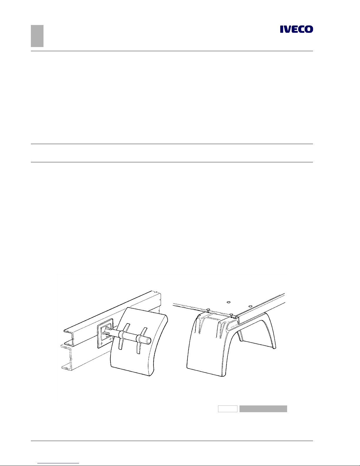
58
EUROCARGO Euro 6 – CHASSIS INTERVENTIONS
CHASSIS INTERVENTIONS
2.20 REAR UNDER-RUN PROTECTION (RUP)
– Printed 603.95.747 – 1st Ed. - Base 12/2013
2.20 REAR UNDER-RUN PROTECTION (RUP)
The maximum distance between the rear under-run protection device (RUP = Rear Underrun Protection) and the rear-most
point of the superstructure is 400 mm, less the deformation observed in the approval phase (on average 10 mm).
If the changes on the chassis require the adaptation of the rear overhang, the under-run protection must be placed by performing
the same connection to the chassis as provided in the original version.
In the transformation of the vehicle or in the application of special equipment (e.g. rear tail lifts), it may be necessary to modify the
structure of the under-run. The intervention shall not change the resistance characteristics and the original rigidity.
The compliance of the modified device with standards in force must be demonstrated to the competent authorities by appropriate
documentation or test certificates.
Note
On vehicles with a GVW higher than 14 tons it is necessary to use a rear under-run protection similar to the one of vehicles with
GVW 18 tons, or choose for the opt 4667 provided for vehicles which use a 3rd axis.
2.21 REAR MUD GUARDS AND WHEEL ARCHES
On cab version vehicles without rear fenders, the Bodybuilder must implement solutions equal to those provided by IVECO.
For the realisation of the fenders, the wheel arch boxes and the shaping of the superstructure, keep in mind that:
● the free shaking of the wheels must be ensured even in the conditions of use with chains; any indications on limit values can be
requested via the Support Service;
● the width of the fender must be greater than the maximum dimensions occupied by the tyres, within the limits set by the
regulations;
● the support structure of the fender must have adequate strength and be able to limit the vibrations;
● the connection can be made on the vertical rib of the side members of the vehicle (using only the already existing holes) or
directly applied under the superstructure (see Figure 2.31).
The first and the second point are also to be considered in the implementation of wheel arches.
91472
Figure 31
Page 87

EUROCARGO Euro 6 – CHASSIS INTERVENTIONS
CHASSIS INTERVENTIONS
2.22 RAIN FLAP
59
– Printed 603.95.747 – 1st Ed. - Base 12/2013
2.22 RAIN FLAP
In cases where legislation requires it and if not present yet, it is necessary to ensure that the complete vehicle is equipped with
suitable rain flaps. For installation, it is necessary to comply with the distances required by the laws in force.
2.23 SIDE PROTECTIONS
In some countries, regulations (national or EC) require the application of side protections. Compliance with the required characteristics should be assured by the Bodybuilder who handles completion of the vehicle, if it was not already equipped as such originally
(optional setting).
In permanently applied superstructures (e.g. fixed bodies, vans) side protection can be applied on the basis of their structure (e.g.
backbone of the floor beams), while for mobile superstructures (e.g. tippers, interchangeable equipment, hook lifts) the connection
can be made by means of suitable supports on the counter chassis or directly on the chassis. In the latter case, use the existing holes
on the vertical rib of the side member as much as possible, in compliance with Chapter 2.2 ( ➠ Page 7).
In implementing the outer protection, as required by the regulations (e.g. EC Directive), it is permitted to use either a single section
with a surface extending in the vertical longitudinal sections, with pre-set dimensions and distances between them.
The protection must be connected to the support structures in order to be quickly removed or reversed in case of maintenance
or repair of the units behind them
Special attention should be paid to ensure the distances established by the Regulations in relation to the various parts of the vehicle.
Figure 2.32 shows:
● a side protection solution in case of a fixed body, made in compliance with the relevant EC Directives,
● an example of a support for fixing the combined lateral protection and the mudguard for the rear wheels, suitable for mobile
superstructures.
Page 88
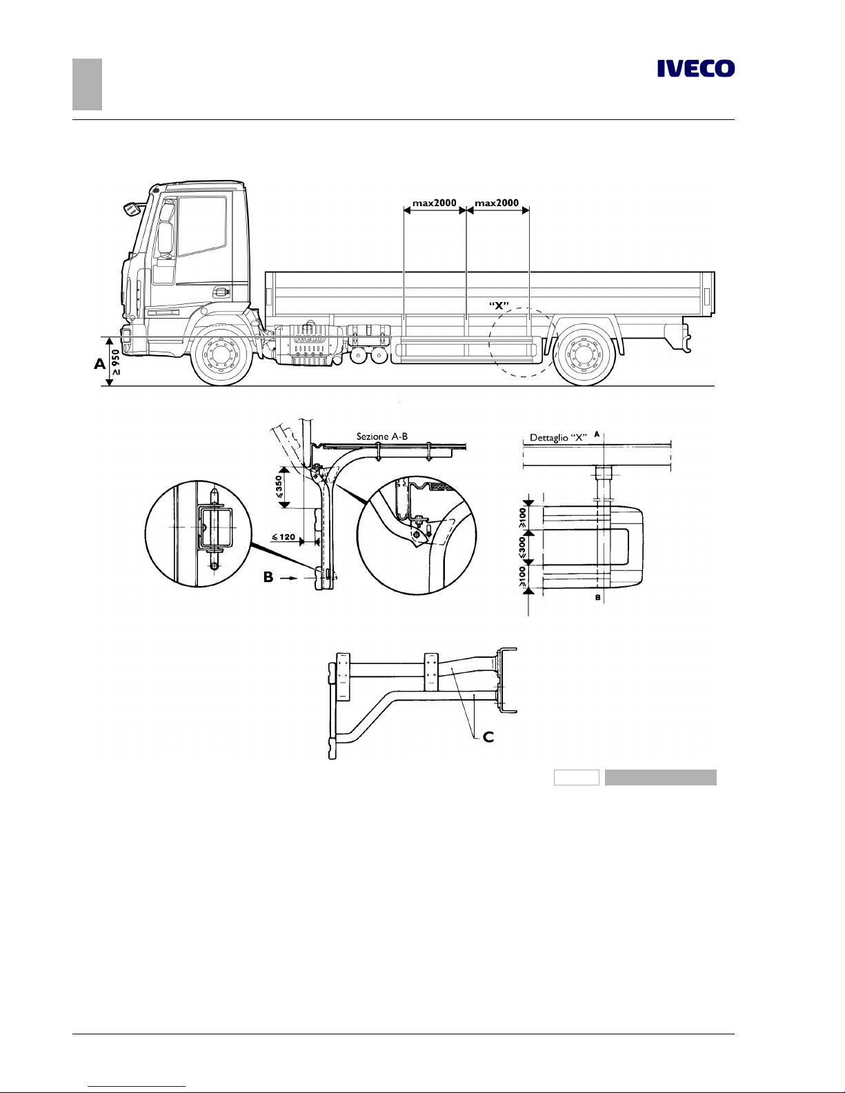
60
EUROCARGO Euro 6 – CHASSIS INTERVENTIONS
CHASSIS INTERVENTIONS
2.23 SIDE PROTECTIONS
– Printed 603.95.747 – 1st Ed. - Base 12/2013
196788
Figure 32
A With the lower part of the superstructure over 1300 mm
from the ground, or with the width of the superstructure
below the external tyre dimension.
B Permissible sag under the test load:≤30 mm on the
rear part (last 250 mm of the device);≤150 mm on
the remaining parts
C Support for fixing the combined lateral protection and the
mudguard for the rear wheels
Page 89

EUROCARGO Euro 6 – CHASSIS INTERVENTIONS
CHASSIS INTERVENTIONS
2.24 FRONT UNDER-RUN PROTECTION (FUP)
61
– Printed 603.95.747 – 1st Ed. - Base 12/2013
2.24 FRONT UNDER-RUN PROTECTION (FUP)
For the front under-run protection bar (FUP = Front Underrun Protection) are provided different fixing positions to the chassis.
So it is possible to comply with the EC 2000/40 Directive even with the new vehicle setting after the fitting, the new loads on the
axes and/or the use of any different tyres.
On vehicles 120E with added third axle it is necessary to use the front under-run protection of the vehicle 140E.
On the vehicles 150E, 180E and 190EL the first entrance step in the cab is fixed to the FUP; the change of its position leads to the
replacement of the fixing bracket of the step in order to keep its position unchanged with respect to the cab.
2.25 REAR-VIEW MIRRORS
The table shows the main dimensions of the arms of the approved rear-view mirrors according to the maximum width of the complete vehicle and the position of the driver.
Table 2.16 - Arms for approved rear-view mirrors
Vehicle width
Arms dimensions a x b x c (mm)
Left-hand drive Right-hand drive
Driving side Passenger side Driving side Passenger side
2300 ÷ 2450 152 x 793 x 151 154 x 793 x 158 154 x 793 x 158 152 x 793 x 151
2400 ÷ 2500 209 x 793 x 209 211 x 793 x 214 211 x 793 x 214 209 x 793 x 209
2500 ÷ 2600
310 x 793 x 303 304 x 793 x 310 304 x 793 x 310 310 x 793 x 303
209 x 793 x 209 211 x 793 x 214 211 x 793 x 214 209 x 793 x 209
Page 90
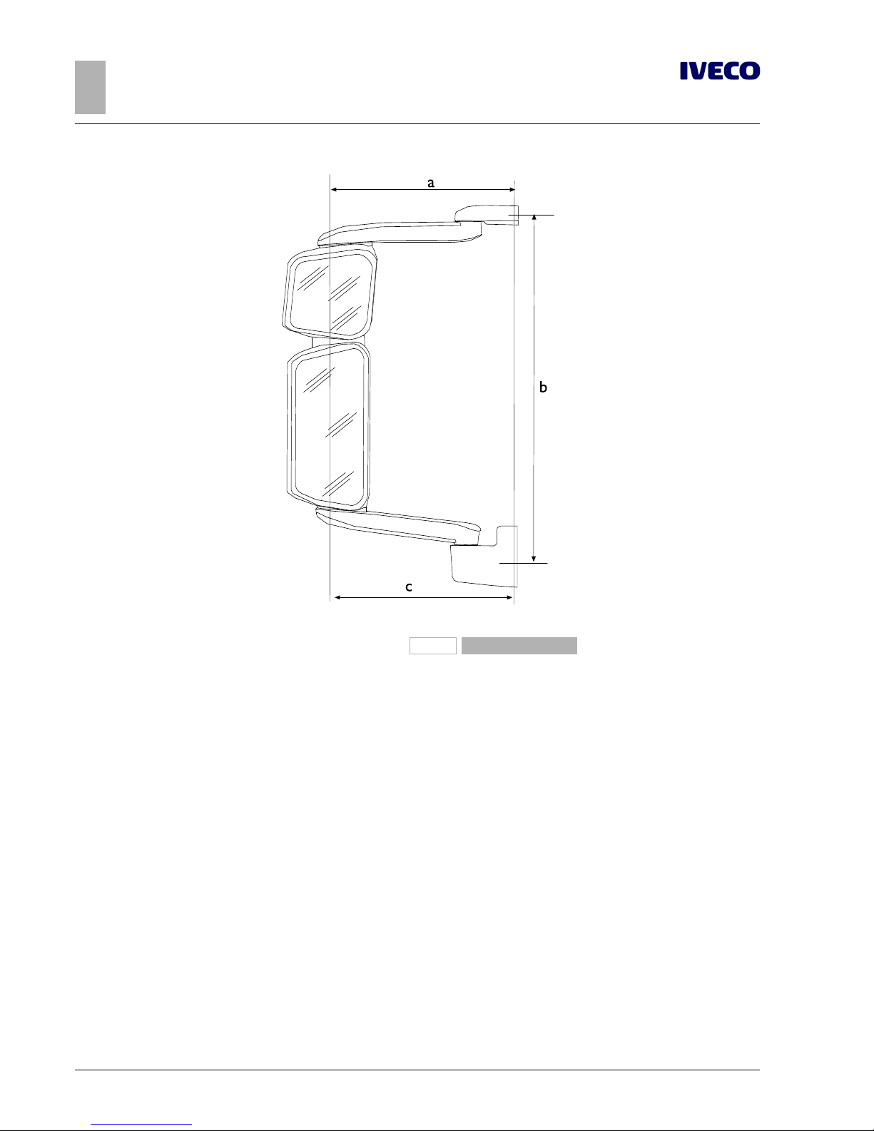
62
EUROCARGO Euro 6 – CHASSIS INTERVENTIONS
CHASSIS INTERVENTIONS
2.25 REAR-VIEW MIRRORS
– Printed 603.95.747 – 1st Ed. - Base 12/2013
131013
Figure 33
Page 91

- Printed 603.95.747 – Base 12/2013
SECTION 3
APPLICATIONS OF
SUPERSTRUCTURES
Page 92

- Printed 603.95.747 – Base 12/2013
Page 93

EUROCARGO Euro 6 – APPLICATIONS OF SUPERSTRUCTURES
APPLICATIONS OF SUPERSTRUCTURES
Contents
3
– Printed 603.95.747 – 1st Ed. - Base 12/2013
Contents
3.1 CONSTRUCTION OF THE COUNTER
CHASSIS . . . . . . . . . . . . . . . . . . . . . . . . . . . . . . 5
Material . . . . . . . . . . . . . . . . . . . . . . . . . . . . 5
Sizing of profiles . . . . . . . . . . . . . . . . . . . . . . . 5
Aluminium counter chassis . . . . . . . . . . . . . . . . 6
3.2 ELEMENTS MAKING UP THE COUNTER
CHASSIS . . . . . . . . . . . . . . . . . . . . . . . . . . . . . . 7
Longitudinal profiles . . . . . . . . . . . . . . . . . . . . . 7
Cross members . . . . . . . . . . . . . . . . . . . . . . . 9
3.3 CONNECTION BETWEEN CHASSIS AND
COUNTER CHASSIS . . . . . . . . . . . . . . . . . . . . . 11
Choosing the type of connection . . . . . . . . . . . . 11
Connection characteristics . . . . . . . . . . . . . . . 12
Connection with brackets . . . . . . . . . . . . . . . . 13
Connections with greater elasticity . . . . . . . . . . 15
Connections with clevis fasteners or clamps . . . . . 15
Connection with longitudinal and transverse
sealing plates (rigid junction) . . . . . . . . . . . . . . 16
Mixed connection . . . . . . . . . . . . . . . . . . . . . 17
3.4 CONTAINER APPLICATION . . . . . . . . . . . . 18
Fixed bodies . . . . . . . . . . . . . . . . . . . . . . . . 18
Tipper bodies . . . . . . . . . . . . . . . . . . . . . . . . 20
Heavy-duty services . . . . . . . . . . . . . . . . . . . . 21
Light-duty services . . . . . . . . . . . . . . . . . . . . . 22
Roll off containers . . . . . . . . . . . . . . . . . . . . . 23
3.5 TRACTOR FOR SEMI-TRAILER . . . . . . . . . . . 24
3.6 TRANSPORT OF INSEPARABLE MATERIALS
(TRAILER TRUCKS) . . . . . . . . . . . . . . . . . . . . . 24
3.7 INSTALLATION OF TANKS AND LOOSE
MATERIAL CONTAINERS . . . . . . . . . . . . . . . . . 24
3.8 INSTALLING A CRANE . . . . . . . . . . . . . . . . 26
Crane behind cab . . . . . . . . . . . . . . . . . . . . . 27
Crane at rear overhang . . . . . . . . . . . . . . . . . . 31
Removable cranes . . . . . . . . . . . . . . . . . . . . . 34
3.9 INSTALLATION OF TAIL LIFTS . . . . . . . . . . . 34
Base configuration for tail lifts . . . . . . . . . . . . . . 39
VEHH configuration for tail lifts . . . . . . . . . . . . 40
3.10 INTERCHANGEABLE OUTFITS . . . . . . . . . . 40
3.11 CONSTRUCTION OF BOX TRUCK
BODIES . . . . . . . . . . . . . . . . . . . . . . . . . . . . . 41
3.12 TILT BEDS (BREAKDOWN RECOVERY)
. . . . . . . . . . . . . . . . . . . . . . . . . . . . . . . . . . . 41
3.13 VEHICLES FOR COUNCIL, FIRE SERVICE
AND SPECIAL USES . . . . . . . . . . . . . . . . . . . . . 41
3.14 FRONT INSTALLATION OF SNOW
PLOUGH ATTACHMENTS . . . . . . . . . . . . . . . . . 42
3.15 APPLICATION OF A WINCH . . . . . . . . . . . 42
3.16 CONCRETE MIXER INSTALLATION . . . . . . 43
Page 94

4
EUROCARGO Euro 6 – APPLICATIONS OF SUPERSTRUCTURES
APPLICATIONS OF SUPERSTRUCTURES
– Printed 603.95.747 – 1st Ed. - Base 12/2013
Page 95

EUROCARGO Euro 6 – APPLICATIONS OF SUPERSTRUCTURES
APPLICATIONS OF SUPERSTRUCTURES
3.1 CONSTRUCTION OF THE COUNTER CHASSIS
5
– Printed 603.95.747 – 1st Ed. - Base 12/2013
APPLICATIONS OF SUPERSTRUCTURES
NOTE The specific instructions below are integrated into the requirements stated in Section 1 "GENERAL INFORMATION" in the
general rules.
3.1 CONSTRUCTION OF THE COUNTER CHASSIS
The purpose of the counter chassis is to ensure a uniform load distribution on the vehicle chassis and the necessary cooperation
with it to the effects of resistance and stiffness, depending on the vehicle's specific use.
Material
In general, if the stresses on the counter chassis are not high, the material for its realisation may have characteristics inferior to
those of the frame, notwithstanding the need to have good characteristics of weldability and limits that are not lower than the values (1) shown in Table 3.1.
In cases where the stress limits require it (e.g. for crane applications), or if you want to avoid high section height, materials with
superior mechanical characteristics may be used. You should, however, keep in mind that the reduction of the time of inertia of
the reinforcing section involves bending and higher stresses on the main chassis.
Following are the characteristics of certain materials which were taken into account in some of the applications stated below.
Table 3.1 - Material to be used for the construction of superstructures Std IVECO 15-2110 and 15-2812
Name of steel
Breaking strength
[N/mm2]
Yield stress
[N/mm2]
Elongation
IVECO Fe 360D
360 (1) 235 (1) 25% (1)
EUROPE S235J2G3
GERMANY ST37-3N
U.K. 40D
IVECO Fe E420
530 420 21%
EUROPE S420MC
GERMANY QStE420TM
U.K. 50F45
IVECO Fe 510D
520 360 22%
EUROPE S355J2G3
GERMANY ST52-3N
U.K. 50D
Sizing of profiles
The following table shows the values of resistance modulus Wxfor C section profiles recommended by IVECO.
The indicated value Wxrefers to the actual section and takes into account the radii of curvature of the section (can be calculated
with good approximation by multiplying the value obtained by 0.95 considering the section composed of simple rectangles). Profiles
of different section may be used in lieu of those specified, provided that resistance modulus Wxand inertia time Jxof the new C
section are not of a lesser value.
Table 3.2 - Profile dimensions
Resistance modulus W
x
[cm3]
Recommended C profile
[mm]
16 ≤ W ≤ 19 80 X 50 X 4 80 X 60 X 4 80 X 50 X 5
20 ≤ W ≤ 23 80 X 60 X 5
Page 96

6
EUROCARGO Euro 6 – APPLICATIONS OF SUPERSTRUCTURES
APPLICATIONS OF SUPERSTRUCTURES
3.1 CONSTRUCTION OF THE COUNTER CHASSIS
– Printed 603.95.747 – 1st Ed. - Base 12/2013
Resistance modulus W
x
[cm3]
Recommended C profile
[mm]
24 ≤ W ≤ 26 80 X 60 X 6
27 ≤ W ≤ 30 80 X 60 X 7 100 X 50 X 5
31 ≤ W ≤ 33 80 X 60 X 8 100 X 60 X 5
34 ≤ W ≤ 36 100 X 60 X 6
37 ≤ W ≤ 41 100 X 60 X 7
42 ≤ W ≤ 45 80 X 80 X 8 100 X 60 X 8
46 ≤ W ≤ 52 120 X 60 X 6 120 X 60 X 7
53 ≤ W ≤ 58 120 X 60 X 8
59 ≤ W ≤ 65 140 X 60 X 7 120 X 70 X 7
66 ≤ W ≤ 72 140 X 60 X 8 120 X 80 X 8
73 ≤ W≤ 79 160 X 60 X 7
80 ≤ W≤ 88 180 X 60 X 8
89 ≤ W≤ 93 160 X 70 X 7 180 X 60 X 7 140 X 80 X 8
94 ≤ W≤ 104 180 X 60 X 8
105 ≤ W≤ 122 200 X 80 X 6 200 X 60 X 8 180 X 70 X 7
123 ≤ W≤ 126 220 X 60 X 7
127 ≤ W≤ 141 220 X 60 X 8
142 ≤ W≤ 160 200 X 80 X 8 240 X 60 X 8
161 ≤ W≤ 178 220 X 80 X 8 240 X 70 X 8
179 ≤ W≤ 201 250 X 80 X 7 260 X 70 X 8
202 ≤ W≤ 220 250 X 80 X 8 260 X 80 X 8
221 ≤ W≤ 224 220 X 80 X 8 280 X 70 X 8
225 ≤ W≤ 245 250 X 100 X 8 280 X 80 X 8
246 ≤ W ≤ 286 280 X 100 X 8
290 ≤ W ≤ 316 300 X 80 X 8
316 ≤ W ≤ 380 340 X 100 X 8
440 380 X 100 X 8
480 400 X 100 X 8
While the form of resistance represents a decisive value for the stress of the material, the moment of inertia is important mainly
for the flexural hardness and for the quota of the bending moment to be taken, depending on the connection used.
Aluminium counter chassis
When using materials with different characteristics from those of steel (e.g. aluminium), the size and structure of the counter
chassis must be appropriately adjusted.
1. When the contribution of the counter chassis is mainly that of providing a uniform distribution of load and the chassis has
the fundamental task of resistance, aluminium longitudinal profiles having dimensions similar to those indicated for the steel
can be used. Typical examples are fixed bodies, vans and tanks, provided that the supports are continuous and close-up or
in the immediate vicinity of the suspension mounts. An exception is made in cases where high stresses on the chassis require
relatively large sections of the steel reinforcement, cut-resistant links.
2. When the counter chassis is prompted to make a contribution in terms of strength and hardness (e.g. superstructures with
high concentrated loads, tipping bodies, cranes, centre axle trailers, etc..), the use of aluminium is generally not recommended
and should be authorised from time to time by IVECO.
Page 97
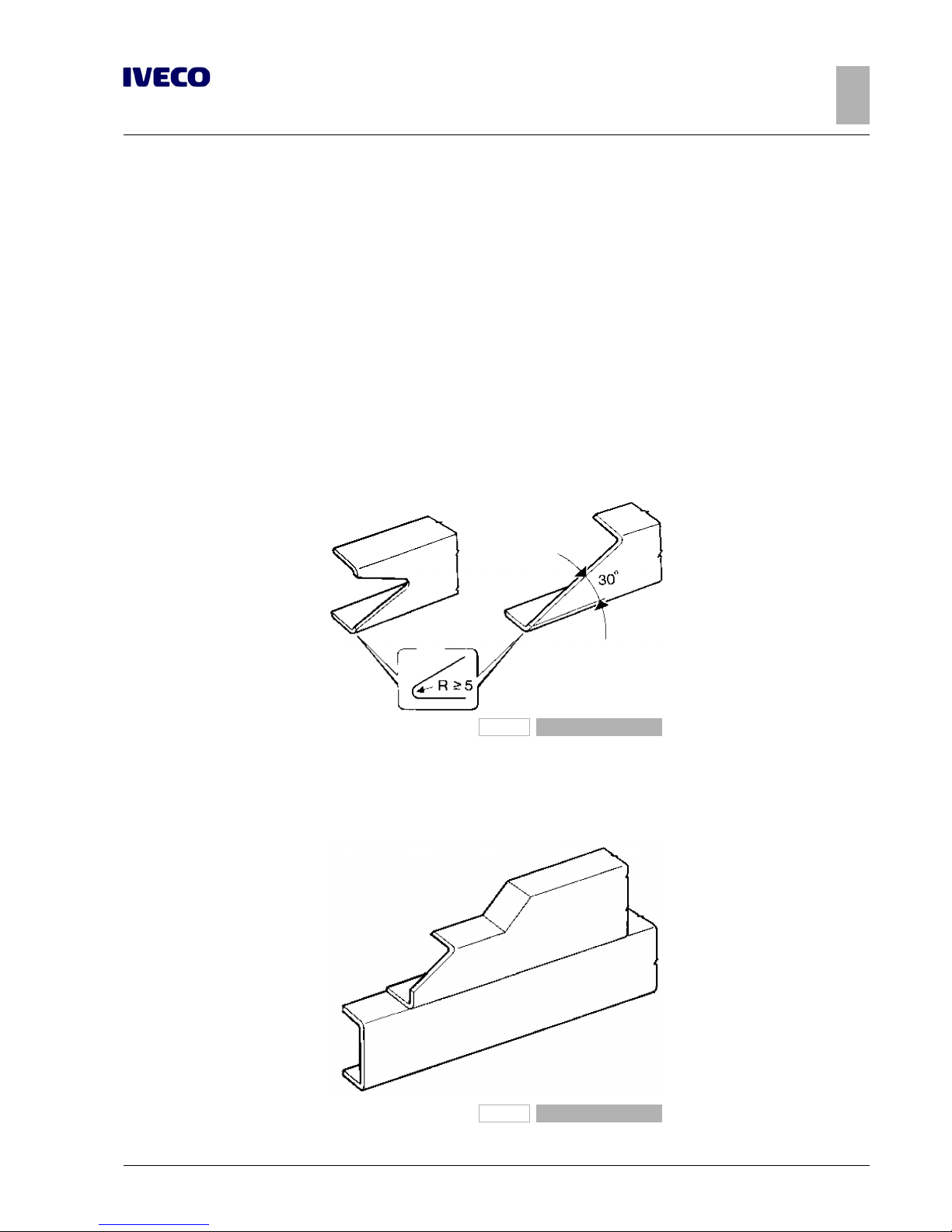
EUROCARGO Euro 6 – APPLICATIONS OF SUPERSTRUCTURES
APPLICATIONS OF SUPERSTRUCTURES
3.2 ELEMENTS MAKING UP THE COUNTER CHASSIS
7
– Printed 603.95.747 – 1st Ed. - Base 12/2013
Please note that in defining the minimum size of the reinforcement profiles in addition to the limit of the allowable stress for
aluminium, reference must be made to the different Elastic Modulus with respect to steel (approx. 7,000 kg/mm2against 21,000
kg/mm2for steel) which involves greater dimensioning of the profiles.
Similarly, when the connection between the chassis and counter chassis is such as to ensure the transmission of the shear stresses
(connection with plates), in checking the stresses at the two ends of the individual section, it is necessary to define the new neutral
axis for this, on the basis of the different elastic modulus of two materials.
The collaboration requirement for aluminium means, in short, large and not very convenient dimensions.
3.2 ELEMENTS MAKING UP THE COUNTER CHASSIS
Longitudinal profiles
The side members of the added structure must be continuous, extended as much as possible toward the front of the vehicle and
towards the rear area of the front spring support; in addition, they must rest on the chassis and not on the brackets.
In order to achieve a gradual reduction of the resistant section, the front ends of the profile must be tapered in height with an
angle not exceeding 30°, or another form of equivalent tapering (see Figure 3.1); the front end in contact with the chassis must
be properly coupled, with min. radius of 5 mm.
91136
Figure 1
In cases in which the components of the cab rear suspension do not allow the passage of the profile in the entire section, this can
be realised as in Figure 3.2. If, due to construction, there are high bending moments on the front of the chassis (e.g. in the case of
a crane with the working range on the front of the vehicle), the profile of the counter chassis must be dimensioned to cope with
such forces.
91137
Figure 2
Page 98
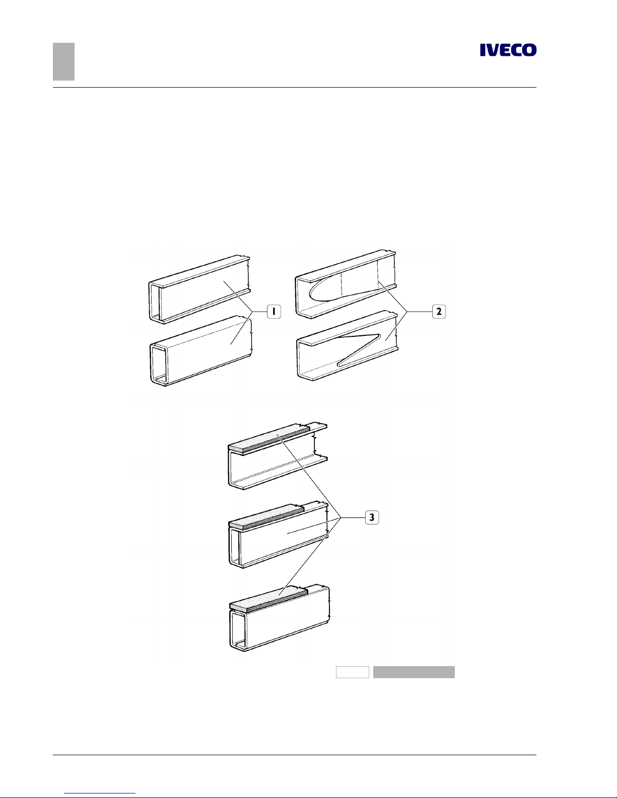
8
EUROCARGO Euro 6 – APPLICATIONS OF SUPERSTRUCTURES
APPLICATIONS OF SUPERSTRUCTURES
3.2 ELEMENTS MAKING UP THE COUNTER CHASSIS
– Printed 603.95.747 – 1st Ed. - Base 12/2013
The possibility of building a counter chassis with a different width from that of the vehicle chassis is permitted only in special cases
(e.g. interchangeable equipment with sliding systems on rollers, where the mechanical or hydraulic devices are unified). In these
cases, precautions must be taken to achieve a correct transmission of forces between the structure of the counter chassis and
the vertical rib of the chassis. This can be achieved by inserting an intermediate profile suitably adapted to the side member, or by
applying an adequately stiffened connecting bracket.
The shape of the profile section is defined taking into account the function of the counter chassis and the type of overlying structure. Open C profiles are advisable when the counter chassis needs to adapt elastically to the vehicle chassis and box sections when
you require greater rigidity of the assembly.
Care should be taken to achieve a gradual transition from the box section to the open section, as in the examples in Figure 3.3.
193867
Figure 3
1. Normal boxed profiles
2. Gradual passage from the boxed section to the open
section
3. 15 mm lintel (width of the wing of the profile)
Page 99
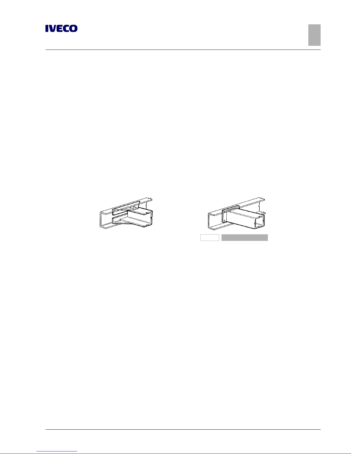
EUROCARGO Euro 6 – APPLICATIONS OF SUPERSTRUCTURES
APPLICATIONS OF SUPERSTRUCTURES
3.2 ELEMENTS MAKING UP THE COUNTER CHASSIS
9
– Printed 603.95.747 – 1st Ed. - Base 12/2013
It is necessary to create continuity of support between the profiles of the counter chassis and those of the chassis; if this is not obtained, the continuity can be restored by means of interposition of strips of sheet metal or light alloy.
If there is to be a rubber undercrawl element we recommend characteristics and thicknesses similar to those used for normal
production (hardness 80 Shore, max thickness 3 mm). Its use can prevent abrasive actions that can cause corrosion in the joining
between materials of different composition (e.g. aluminium and steel).
The dimensioning prescribed for the side members of the various types of superstructure is the recommended minimum value
and, as a rule, is valid for vehicles with wheelbases and rear overhangs provided as standard (see Tables from 3.4 to 3.6 and from
3.8 to 3.13). In all cases similar profiles can be used, but with moments of inertia and resistance that are not lower. These values can
be obtained from the technical documentation of the profile manufacturers.
Cross members
A sufficient number of crossbars, possibly to be placed in correspondence with the fastening clamps to the chassis, must brace the
two sections of the counter chassis.
The crossbars may be open section (e.g. C), or closed section where you would want to impart greater stiffness.
In their connection, suitable gusset plates must be used to give adequate resistance to the connection (see the following Figure on
the left). When you want to achieve greater stiffness in the connection, it can be carried out according to the following Figure on
the right.
193868
Figure 4
Stiffening of the counter chassis
For some superstructures (e.g. tipping bodies, concrete mixers, cranes on rear overhang, superstructures with high centre of gravity), the counter chassis should be stiff in the back.
This can be achieved by increasing the scope of stiffness to obtain:
● boxing the longitudinal sections in the rear area;
● adopting closed section crossbars (see Figure 3.5);
● applying cross diagonals (see Figure 3.6);
● applying a torsion-resistant longitudinal element (see Figure 3.7).
In general the use of boxed longitudinal sections should be avoided in the front part of the counter chassis.
Page 100
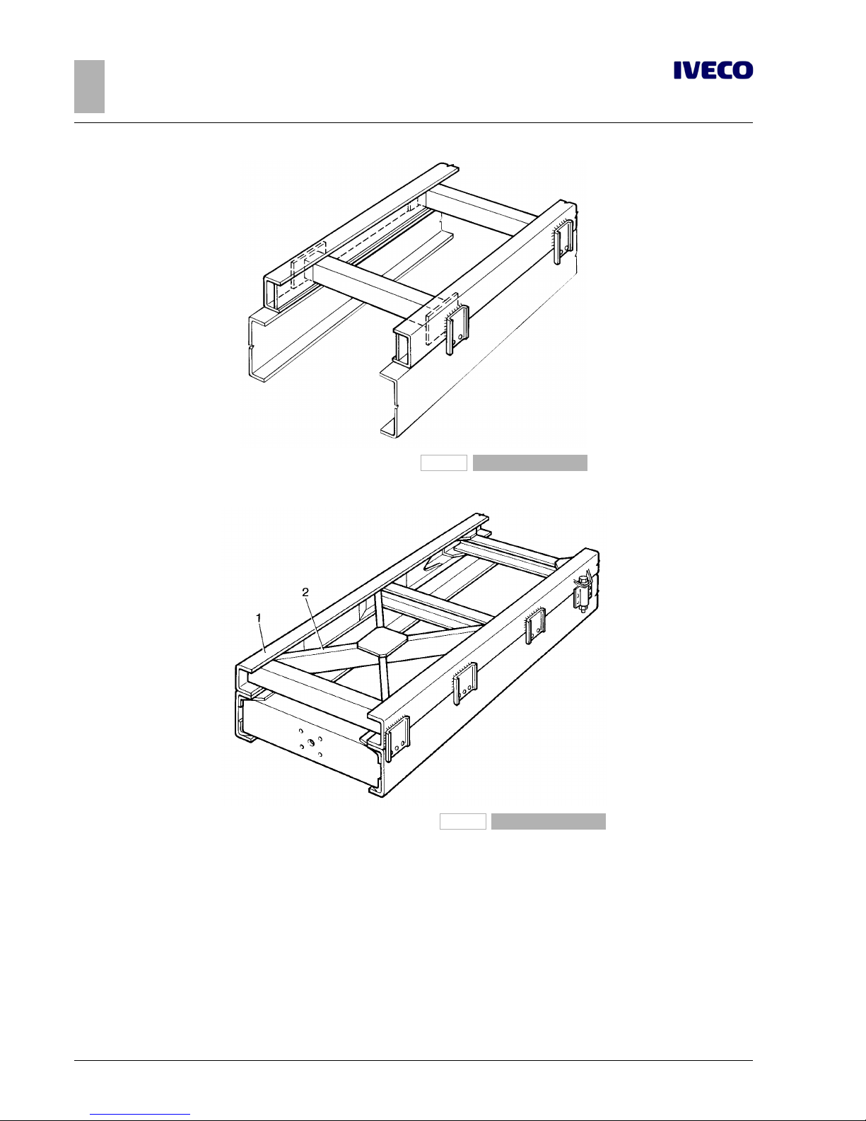
10
EUROCARGO Euro 6 – APPLICATIONS OF SUPERSTRUCTURES
APPLICATIONS OF SUPERSTRUCTURES
3.2 ELEMENTS MAKING UP THE COUNTER CHASSIS
– Printed 603.95.747 – 1st Ed. - Base 12/2013
166684
Figure 5
193869
Figure 6
1 Counter chassis 2. Diagonals
 Loading...