

Page 1

CURSOR TIER 3
SERIES
Industrial application
C10
C10 ENT X
C13
C13 ENT X
CURSOR G-DRIVE
CURSOR 10 TE X
CURSOR 13 TE X
Technical and Repair manual
Page 2

This publication provides unit and relevant component repair
data, specifications, instructions and methodologies.
This publication has been drawn up for qualified and
specialised personnel.
Before performing any operation check that the part relevant
to the unit on which you must work is available along with all
safety devices for accident-prevention, such as, goggles,
helmet, gloves, shoes, etc. and hoisting and transporting
equipment.
Operations are to be performed by following the indications
included here, using the special equipment indicated and
assuring proper repair, compliance with schedule and
operator’s safety requirements.
Each repair must aim to restore operating efficiency and safety
in compliance with the FPT provisions.
FPT cannot be held liable for modifications, alterations or other
interventions non authorised by FPT on the vehicle and if the
unit is warranted the above mentionedinterventions will cause
its expiration.
FPT is not liable for repairing interventions.
FPT will provide further details required to carry out the
interventions and all the instructions that are not included on
this publication.
Data included in this publication may not be up-to-date
therefore subject to Manufacturer’s modifications that can be
added at any time for technical or commercial purposes and
also to meet new law regulations in other Countries.
If issues on this publication differ from what is actually noticed
on the unit, please get in touch with the FPT network before
starting any intervention”.
It is forbidden to copy this text or any of its parts and all
illustrations included.
Publication edited by
FIAT Powerrtrain Technologies
Mkt. Advertising & Promotion
Viale dell’Industria, 15/17
20010 Pregnana Milanese
Milano (Italy)
Print P2D32C003 E -2
nd
Ed. 05.2007
Produced by:
B.U. TECHNICAL PUBLISHING
Iveco Technical Publications
Lungo Stura Lazio, 15/19
10156 Turin - Italy
Page 3

CURSOR ENGINES TIER 3
1
CURSOR ENGINES
Cursor F3A Part 1
Cursor F3B Part 2
Cursor engines application G-Drive Part 3
Print P2D32C003 E Base - May 2007
Page 4

2
CURSOR ENGINES TIER 3
Print P2D32C003 EBase - May 2007
Page 5

RYR
CURSOR ENGINES TIER 3
3
PRELIMINA
Manuals for repairs are split into Parts and Sections, each one of which is marked by a numeral; the contents of these sections are
indicated in the general table of contents.
The sections dealing with things mechanic introduce the specifications, tightening torque values, tool lists, assembly
detaching/reattaching operations, bench overhauling operations, diagnosis procedures and maintenance schedules.
The sections (or parts) of the electric/electronic system include the descriptions of the electric network and the assembly’s
electronic systems, wiring diagrams, electric features of components, component coding and the diagnosis procedures for the
control units peculiar to the electric system.
The manual uses proper symbols in its descriptions; the purpose of these symbols is to classify contained information. In particular,
there have been defined a set of symbols to classify warnings and a set for assistance operations.
EMARKS
SYMBOLS - WARNINGS
Danger for persons
Missing or incomplete observance of these prescriptions can cause serious danger for persons’ safety.
Danger of serious damage for the assembly
Failure to comply, both fully or in part, with such prescriptions will involve serious damage to the assembly and may
sometimes cause the warranty to become null and void.
!
NOTE
General danger
It includes the dangers of above described signals.
Environment protection
Moreover, it describes the correct actions to be taken to ensure that the assembly is used in such a way so as to protect
the environment as much as possible.
It indicates an additional explanation for a piece of information.
Print P2D32C003 E Base - May 2007
Page 6

4
GENERAL WARNINGS
Warnings shown cannot be representativeof all danger situations possibly occurring. Therefore, it is suggested to contact
immediate superiors where a danger situation occurs which is not described.
!
Use both specific and general-purpose toolings according to the prescriptions contained in respective use and
maintenance handbooks. Check use state and suitability of tools not subjected to regular check.
The manual handling of loads must be assessed in advance because it also depends, besides weight, on its size and on
the path.
Handling by mechanical means must be with hoisters proper as for weight as well as for shape and volume. Hoisters,
ropes and hooks used must contain clear indications on maximum carrying capacity acceptable. The use of said means
is compulsorily permitted to authorised personnel only. Stay duly clear of the load, and, anyhow, never under it.
In disassembling operations, always observe provided prescriptions; prevent mechanical parts being taken out from
accidentally striking workshop personnel.
Workshop jobs performed in pairs must always be performed in maximum safety; avoid operations which could be
dangerous for the co-operator because of lack of visibility or of his/her not correct position.
Keep personnel not authorised to operations clear of working area.
You shall get familiar with the operating and safety instructions for the assembly prior to operating on the latter. Strictly
follow all the safety indications found on the assembly.
CURSOR ENGINES TIER 3
Do not leave the running assembly unattended when making repairs.
When carrying out work on the assembly lifted off the ground, verify that the assembly is firmly placed on its supporting
stands, and that the manual/automatic safety devices have been actuated in the event that the assembly is to be lifted
by means of a hoist.
When you h ave to operate on assemblies powered by natural gas, follow the instructions contained in the document,
as well as all the specific safety standards provided for.
Only remove radiator cap when the engine is cold by cautiously unscrewing it in order to let system residual pressure
out.
Inflammable fuel and all inflammable fluidsand liquids must be handled with care, according to what contained on harmful
materials 12-point cards. Refuelling must be performed outdoors with the engine off, avoiding lit cigarettes, free flames
or sparks in order to prevent sudden fires/bursts. Adequately store inflammable, corrosive and polluting fluids and liquids
according to what provided by regulations in force. Compulsorily avoid to use food containers to store harmful liquids.
Avoid to drill or bore pressurised containers, and throw cloths impregnated with inflammable substances into suitable
containers.
Worn out, damaged or consumable parts must be replaced by original spares.
During workshopactivity, always keep the work place clean; timely clear or clean floors from accidentalliquid or oil spots.
Electric sockets and electric equipment necessary to perform r epair interventions must meet safety rules.
Base - May 2007 Print P2D32C003 E
Page 7

CURSOR ENGINES TIER 3
Put on, where required by the intervention, garments and protections provided in accident prevention rules; contact
with moving parts can cause serious injuries. Use suitable, preferably tight-fitted garments, and avoid to use jewels,
scarves, etc.
Do not leave the engine in motion at workshop locations not provided with a pipe to scavenge exhaust gas outside.
Avoid to breathe fumes coming from heating or from paint welding because they can cause damages to health; operate
outdoors or in suitably ventilated areas. Put on proper inspirator if paint powder is present.
Avoid contact with hot water or steam coming from the engine, radiator and pipings because they could cause serious
burns. Avoid direct contact with liquids and fluids present in vehicle systems; where an accidental contact has occurred,
refer to 12-point cards for provisions to make.
Clean the assemblies and carefully verify that they are intact prior to overhauling. Tidy up detached or disassembled
parts with their securing elements (screws, nuts, etc.) into special containers.
Check for the integrity of the parts which prevent screws from being unscrewed: broken washers, dowels, clips, etc.
Self-locking nuts with an insert made of nylon must always be replaced.
Avoid contact of rubber parts with diesel oil, petrol or other not compatible substances.
Before washing under pressure mechanical parts, protect electric connectors, and central units, if present.
5
Tightening screws and nuts must always be according to prescriptions; FPT commercial and assistance network is
available to give all clarifications necessary to perform repair interventions not provided in this document.
Before welding:
- Disconnect all electronic central units, take power cable off battery positive terminal (connect it to chassis bonding)
and detach connectors.
- Remove paint by using proper solvents or paint removers and clean relevant surfices with soap and water.
- Await about 15 minutes before welding.
- Equip with suitable fire resistant protections to protect hoses or other components where fluids or other materials
flow which may catch fire easily on welding.
Should the vehicle be subjected to temperatures exceeding 80°C (dryer ovens), disassemble drive electronic central
units.
The disposal of all liquids and fluids must be performed with full observance of specific rules in force.
Print P2D32C003 E Base - May 2007
Page 8

6
GENERALWARNINGS O N THE ELECTRIC SYSTEM
If an intervention has to be made on the electric/electronic system, disconnect batteries from the system; in this case,
!
always disconnect, as a first one, the chassis bonding cable from batteries negative terminal.
Before connecting the batteries to the system, make sure that the system is well isolated.
Disconnect the external recharging apparatus from the public utility network before taking apparatus pins off battery
terminals.
Do not cause sparks to be generated in checking if the circuit is energised.
Do not use a test lamp in c hecking circuit continuity, but only use proper control apparatuses.
Make sure that the electronic devices wiring harnesses (length, lead type, location, strapping, connection to screening
braiding, bonding, etc.) comply with system and are carefully recovered after repair or maintenance interventions.
Measurements in drive electronic central units, plugged connections and electric connections to components can only
be made on proper testing lines with special plugs and plug bushes. Never use improper means like wires, screwdrivers,
clips and the like in order to avoid the danger of causing a short circuit, as well as of damaging plugged connections, which
would later cause contact problems.
CURSOR ENGINES TIER 3
To start up the engine, do not use fast chargers. Start up must only be performed with either separate batteries or special
truck.
A wrong polarisation of supply voltage in drive electronic central units (for instance, a wrong polarisation of batteries)
can cause them to be destroyed.
Disconnect the batteries from the system during their recharging with an external apparatus.
On connecting, only screw up connector (temperature sensors, pressure sensors etc.) nuts at prescribed tightening
torque.
Before disconnecting the junction connector from an electronic central unit, isolate the system.
Do not directly supply electronic central units servo components at nominal vehicle voltage.
Cables must be arranged such as to result to be parallel to reference plane, i.e. as close as possible to chassis/body
structure.
Once the intervention on the electric system has been completed, recover connectors and wiring harnesses according
to original arrangement.
NOTE
Connectors presentmust be seen from cable side. Connectors views contained in the manual arerepresentative of cable
side.
Base - May 2007 Print P2D32C003 E
Page 9
CURSOR ENGINES TIER 3
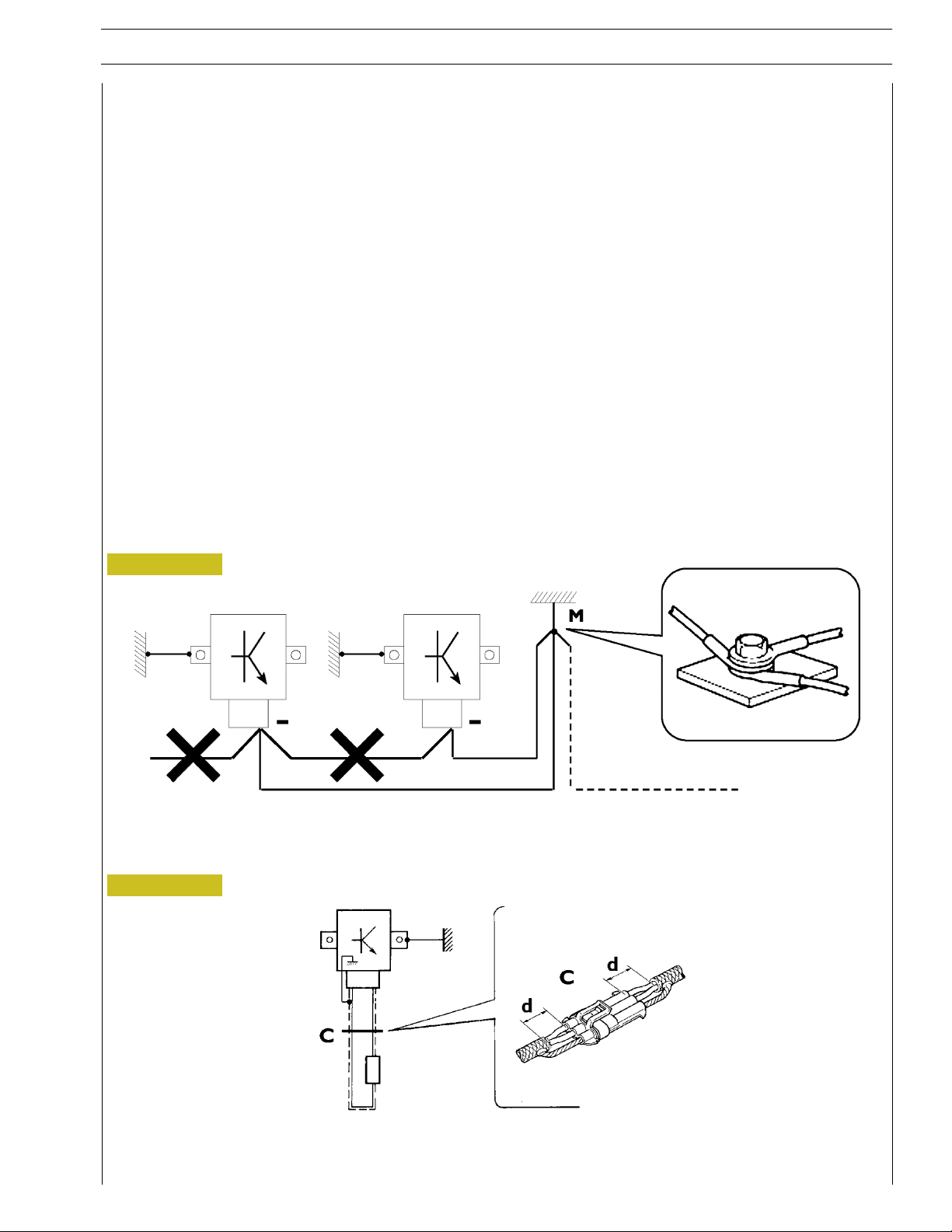
Bonding and screening
Negative leads connected to a system bonded point must be both as short and possible and “star“-connected to each other, trying
then to have their centering tidily and properly made (Figure 1, re. M).
Further, following warnings are to be compulsorily observed for electronic components:
- Electronic central units must be connected to system bonding when they are provided with a metallic shell.
- Electronic central units negative c ables must be connected both to a system bonding point such as the dashboard opening
bonding (avoiding “serial“ or “chain“ connections), and to battery negative terminal.
- Analog bonding (sensors), although not connected to battery negative system/terminal bonding, must have optimal isolation.
Consequently, particularly considered must be parasitic resistances in lugs: oxidising, clinching defects, etc.
- Screened circuits braiding must only electrically contact the end towards the central unit entered by the signal (Figure 2).
- If junction connectors are present, unscreened section d, near them, must be as short as possible (Figure 2).
- Cables must be arranged such as to result to be parallel to reference plane, i.e. as close as possible to chassis/body structure.
7
Figure 1
1. NEGATIVE CABLES “STAR“ CONNECTION TO SYSTEM BONDING M
Figure 2
88039
2. SCREENING THROUGH METALLIC BRAIDING OF A CABLE TO AN ELECTRONIC COMPONENT — C. CONNECTOR
d. DISTANCE ! 0
Print P2D32C003 E Base - May 2007
Page 10

8
CURSOR ENGINES TIER 3
OPTIONAL ELECTRICAL AND MECHANICAL PARTS INSTALLATIONS
Assemblies shall be modified and equipped with additions - and their accessories shall be fitted - in accordance with the assembling
directives issued by FPT.
It is reminded that, especially about the electric system, several electric sockets are provided for as series (or optional) sockets in
order to simplify and normalise the electrical intervention that is care of preparation personnel.
It is absolutely forbidden to make modifications or connections to electric central units wiring harnesses; in particular,
the data interconnection line between central units (CAN line) is to be considered inviolable.
CONVERSIONS BETWEEN THE MAIN UNITS OF MEASUREMENT OF THE INTERNATIONAL SYSTEM AND MOST USED DERIVED QUANTITIES
Power
1 kW = 1.36 metric HP
1 kW = 1.34 HP
1 metric HP = 0.736 kW
1 metric HP = 0.986 HP
1 HP = 0.746 kW
1 HP = 1.014 metric HP
Torque
1 Nm = 0.1019 kgm
1 kgm = 9.81 Nm
Revolutions per time unit
1 rad/s = 1 rpm x 0.1046
1 rpm = 1 rad/s x 9.5602
Pressure
1 bar = 1.02 kg/cm
1 kg/cm
1bar = 10
2
= 0.981 bar
5
2
Pa
Where accuracy is not particularly needed:
- Nm unit is for the sake of simplicity converted into kgm according to ratio 10:1
1 kgm = 10 Nm;
2
- bar unit is for the sake of simplicity converted into kg/cm
2
1 kg/cm
=1bar.
according to ratio 1:1
Temperature
0° C=32° F
1° C = (1 x 1.8 + 32) ° F
Base - May 2007 Print P2D32C003 E
Page 11

CURSOR ENGINES F3A
1
Part 1
CURSOR ENGINES F3A
Section
General specifications
Fuel 2
Duty - Industrial application 3
Overhaul and technical specifications 4
Tools 5
Safety prescriptions Appendix
1
PREFACE TO USER’S GUIDELINE MANUAL
Section 1 describes the F3A engine illustrating its features
and working in general.
Section 2 describes the type of fuel feed.
Section 3 relatesto the specific dutyand is dividedin four separate parts:
1. Mechanical part, related to the engine overhaul,
limited to those components with different characteristics
based on the relating specific duty.
2. Electrical part, concerning wiring harness, electrical
and electronic equipment with different characteristics
based on the relating specific duty.
3. Maintenance planning and specific overhaul.
4. Troubleshooting part dedicated to the operators who,
being entitled to provide technical assistance, shall have simple
and direct instructions to identify the causeof the major inconveniences.
Sections 4 and 5 illustrate the overhaul operations of the engine overhaul on standand the necessary equipment to execute
such operations.
The appendix contains a list of the general safety regulations
to be respected by all installation and maintenance engineers
in order to prevent serious accidents taking place.
Print P2D32C003 E Base - May 2007
Page 12

2
CURSOR ENGINES F3A
Print P2D32C003 EBase - May 2007
Page 13
CURSOR ENGINES F3A
3
SPECIAL REMARKS
Diagrams and symbols have been widely used to give a clearer and more immediate illustration of the subject being dealt with, (see
next page) instead of giving descriptions of some operations or procedures.
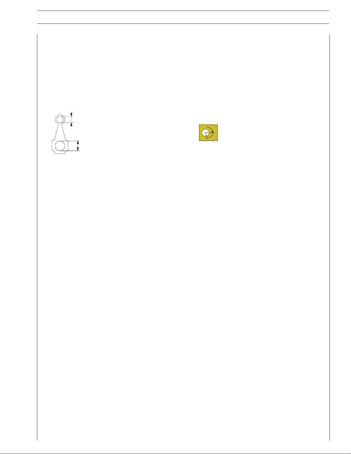
Example
∅
Ø 1 = housing for connecting rod small end bush
1
Ø 2 = housing for connecting rod bearings
∅
2
Tighten to torque
Tighten to torque + angular value
α
Print P2D32C003 E Base - May 2007
Page 14
4
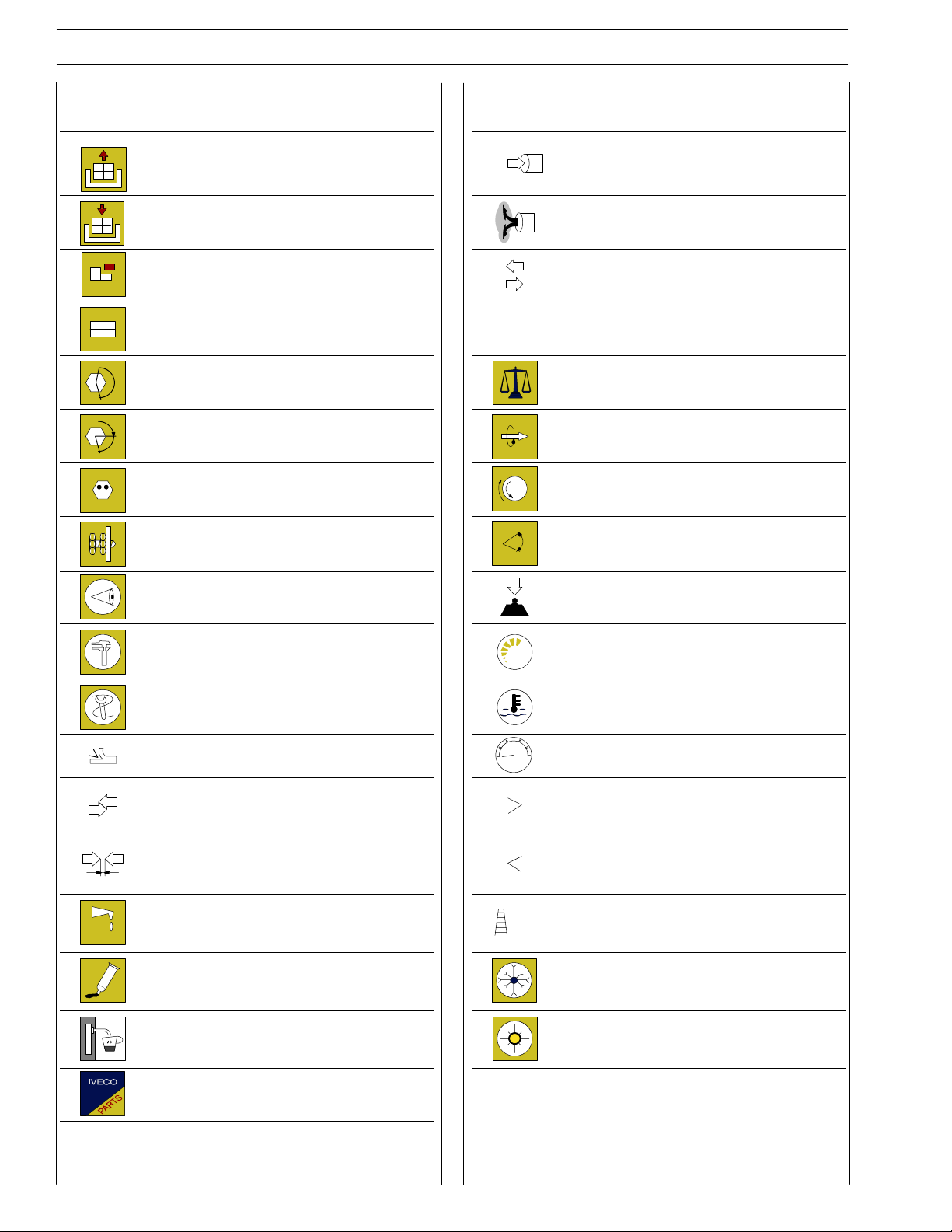
SYMBOLS - ASSISTANCE OPERATIONS
CURSOR ENGINES F3A
Removal
Disconnection
Refitting
Connection
Removal
Disassembly
Fitting in place
Assembly
ρ
Tighten to torque
Tighten to torque + angle value Rolling torque
α
Press or caulk Rotation
Regulation
Adjustment
Visual inspection
Fitting position check
Intake
Exhaust
Operation
Compression ratio
Tolerance
Weight difference
Angle
Angular value
Preload
Measurement
Value to find
Number of revolutions
Check
Equipment Temperature
Surface for machining
Machine finish
Interference
Strained assembly
Thickness
Clearance
Lubrication
Damp
Grease
Sealant
Adhesive
bar
Pressure
Oversized
Higher than….
Maximum, peak
Undersized
Less than….
Minimum
Selection
Classes
Oversizing
Temperature < 0 °C
Cold
Winter
Temperature > 0 °C
Air bleeding
Hot
Summer
Replacement
Original spare parts
Print P2D32C003 EBase - May 2007
Page 15

CURSOR ENGINES F3A
UPDATING
Section Description Page Date of revision
5
Print P2D32C003 E Base - May 2007
Page 16

6
CURSOR ENGINES F3A
Print P2D32C003 EBase - May 2007
Page 17

CURSOR ENGINES F3A
SECTION 1 - GENERAL SPECIFICATIONS
SECTION 1
General Specifications
Page
CORRESPONDENCE BETWEEN TECHNICAL
AND COMMERCIAL CODES 3............
VIEWS OF THE ENGINE
(ONLY FOR TYPE F3AE0684P*E904) 5......
VIEWS OF THE ENGINE (FOR TYPES: F3AE0684P*E906 -
F3AE0684L*E906 - F3AE0684P*E905) 8.....
VIEWS OF THE ENGINE
(ONLY FOR TYPE: F3AE0684N*E907) 11.....
VIEWS OF THE ENGINE
(ONLY FOR TYPE: F3AE0684N*E907) 14.....
LUBRICATION DIAGRAM
(ONLY FOR TYPE: F3AE0684P*E904 ) 16.....
LUBRICATION DIAGRAM
(FOR TYPES: F3AE0684P*E906 - F3AE0684L*E906 -
F3AE0684P*E905) 17.....................
1
LUBRICATION DIAGRAM
(ENGINES F3AE0684N*E907) 18............
- Oil pump 19.............................
- Overpressure valve 19.....................
- Oil pressure control valve 20................
- Heat exchanger (for type: F3AE0684P*E906 -
F3AE0684L*E906 - F3AE0684P*E905 -
F3AE0684N*E907) 20.....................
- Heat exchanger
(only for type: F3AE0684P*E904) 21..........
- By-pass valve 22..........................
- Thermostatic valve 22......................
- Engine oil filters 22........................
COOLING 23.............................
- Description 23...........................
- Operation 23............................
- Water pump 25..........................
- Thermostat 25...........................
TURBOCHARGING 26......................
EGR EXHAUST GAS
RECIRCULATION SYSTEM 27.............
INTERNAL EGR ACTING ON
THEINTAKEVALVES 27..................
Base - May 2007Print P2D32C003 E
Page 18

2
SECTION 1 - GENERAL SPECIFICATIONS
CURSOR ENGINES F3A
Base - May 2007 Print P2D32C003 E
Page 19

CURSOR ENGINES F3A
SECTION 1 - GENERAL SPECIFICATIONS
CORRESPONDENCE BETWEEN TECHNICAL AND COMMERCIAL CODES
Technical Code Commerciale Code
F3AE0684P*E904
F3AE0684P*E906
F3AE0684L*E906
F3AE0684P*E905 C10 ENT X
F3AE0684N*E907
F3AE9687A*E001
F3AE9687B*E001
3
F3AE9687C*E001
Base - May 2007Print P2D32C003 E
Page 20

4
SECTION 1 - GENERAL SPECIFICATIONS
CURSOR ENGINES F3A
Base - May 2007 Print P2D32C003 E
Page 21
CURSOR ENGINES F3A
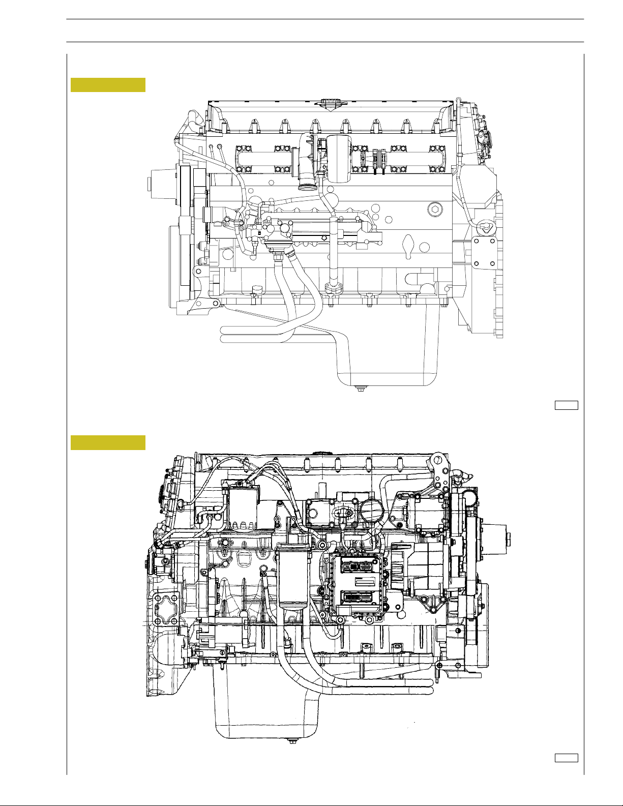
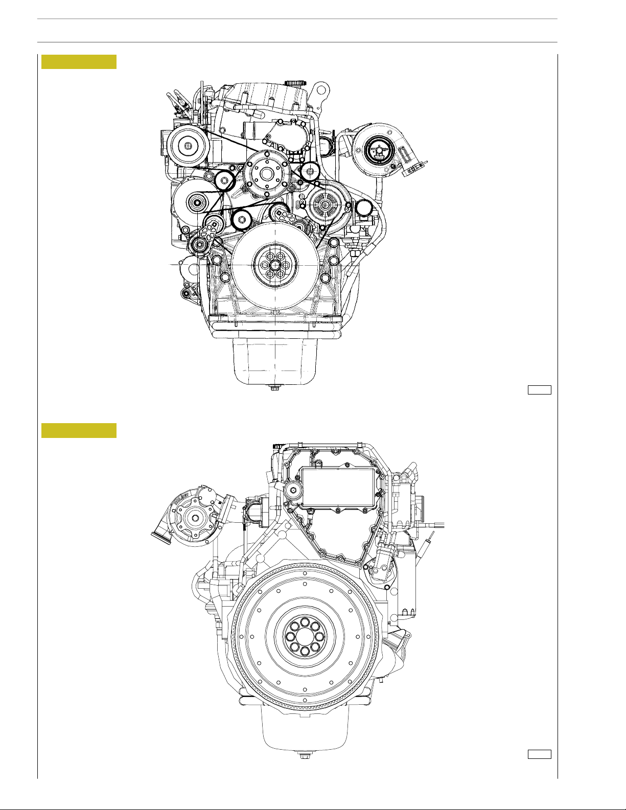
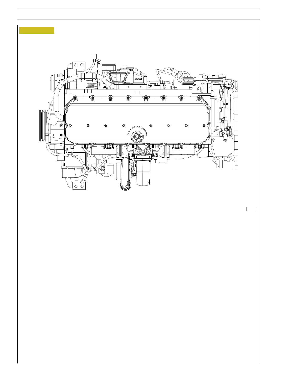
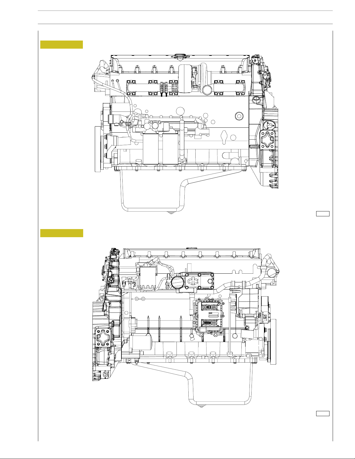
VIEWS OF THE ENGINE (ONLY FOR TYPE F3AE0684P*E904)
Figure 1
SECTION 1 - GENERAL SPECIFICATIONS
5
Figure 2
104224
LEFT-HAND SIDE VIEW
RIGHT-HAND SIDE VIEW
104225
Base - May 2007Print P2D32C003 E
Page 22
6
SECTION 1 - GENERAL SPECIFICATIONS
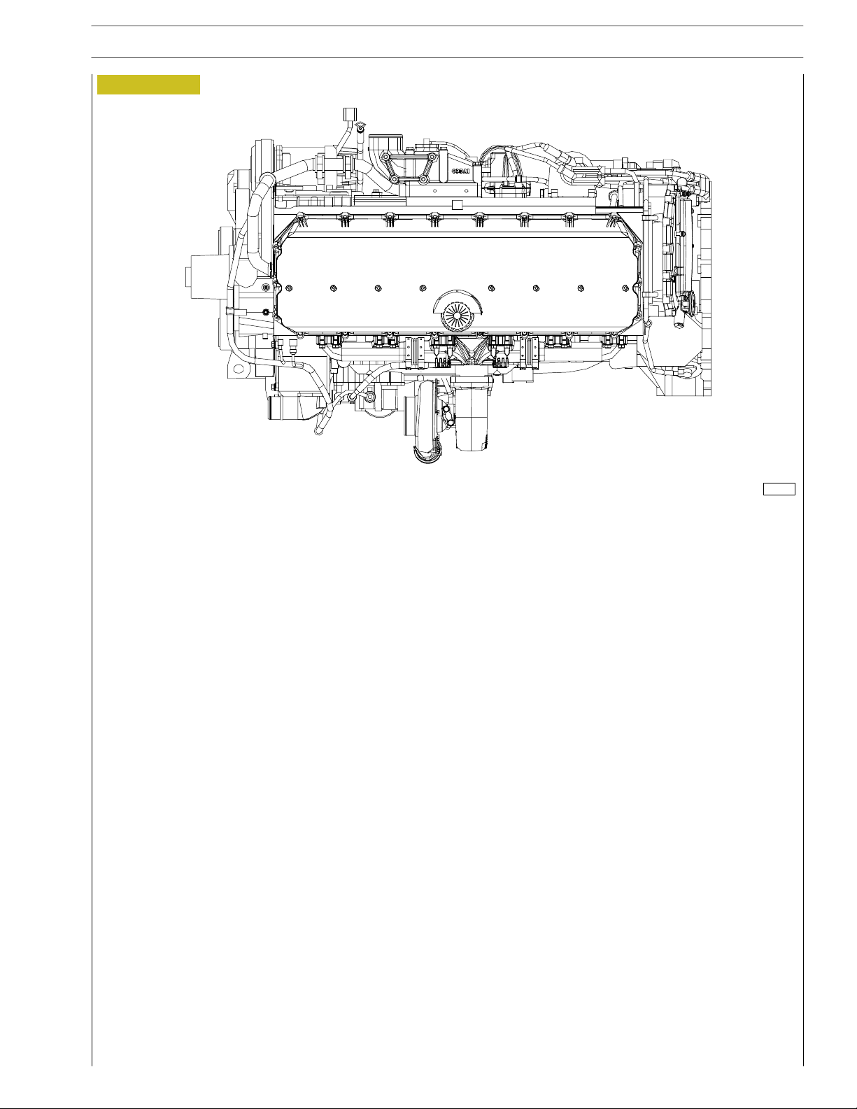
Figure 3
CURSOR ENGINES F3A
Figure 4
104226
FRONT VIEW
104227
REAR VIE W
Base - May 2007 Print P2D32C003 E
Page 23
CURSOR ENGINES F3A
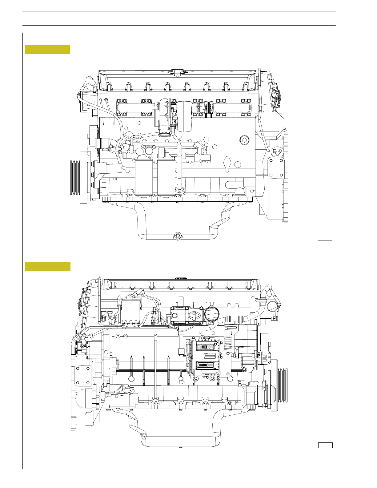
Figure 5
SECTION 1 - GENERAL SPECIFICATIONS
7
TOP VIEW
104228
Base - May 2007Print P2D32C003 E
Page 24
8
SECTION 1 - GENERAL SPECIFICATIONS
CURSOR ENGINES F3A
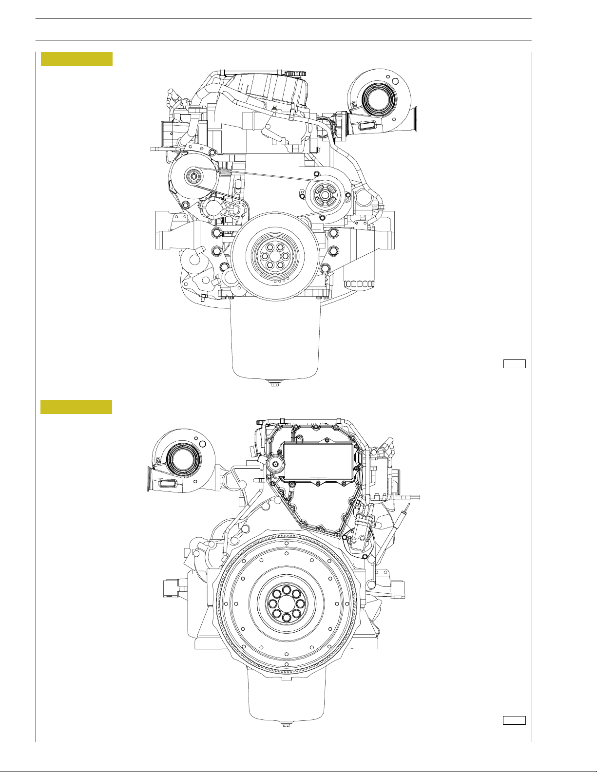
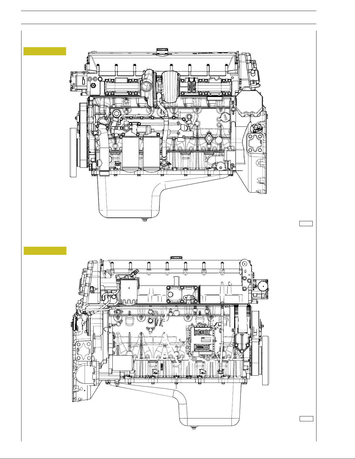
VIEWS OF THE ENGINE (FOR TYPES: F3AE0684P*E906 - F3AE0684L*E906 - F3AE0684P*E905)
Figure 6
Figure 7
104229
LEFT-HAND SIDE VIEW
104230
RIGHT SIDE VIEW
Base - May 2007 Print P2D32C003 E
Page 25
CURSOR ENGINES F3A
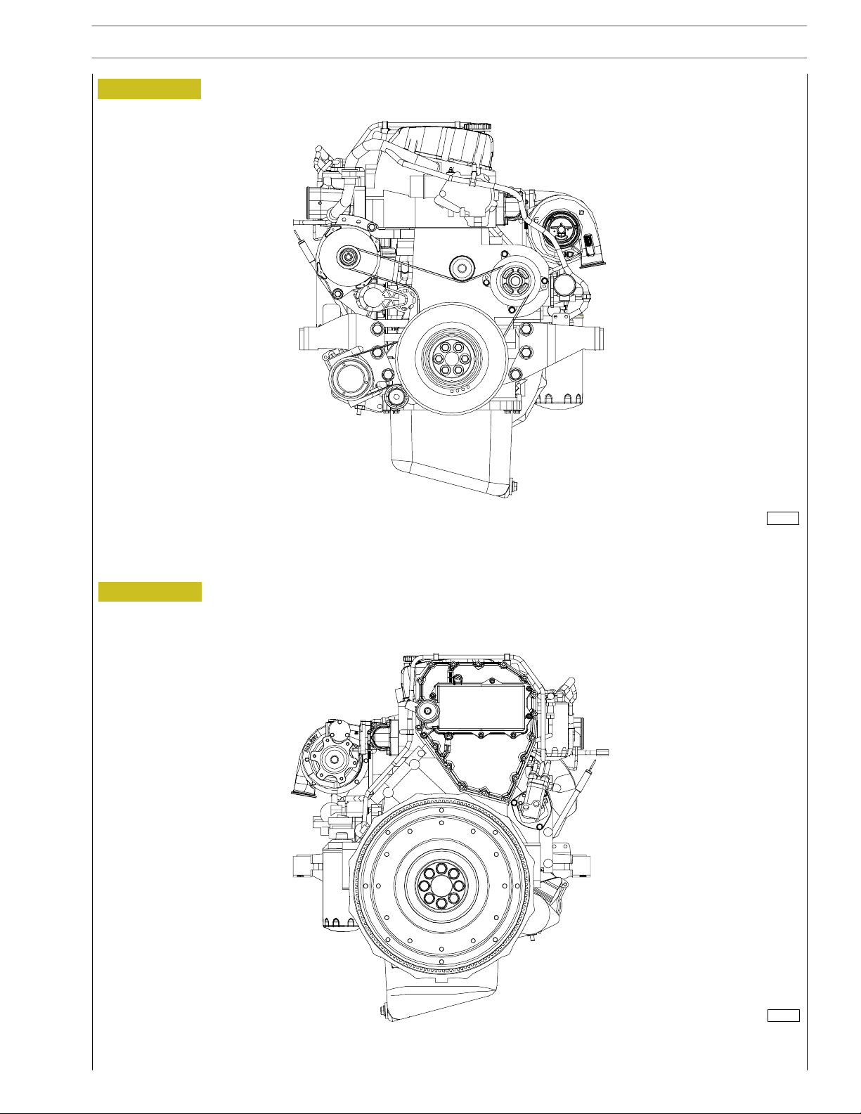
Figure 8
SECTION 1 - GENERAL SPECIFICATIONS
9
Figure 9
104231
FRONT SIDE VIEW
REAR SIDE VIEW
104232
Base - May 2007Print P2D32C003 E
Page 26
10
SECTION 1 - GENERAL SPECIFICATIONS
Figure 10
CURSOR ENGINES F3A
TOP SIDE VIEW
104233
Base - May 2007 Print P2D32C003 E
Page 27
CURSOR ENGINES F3A
VIEWS OF THE ENGINE (ONLY FOR TYPE: F3AE0684N*E907)
Figure 11
SECTION 1 - GENERAL SPECIFICATIONS
11
Figure 12
104755
LEFT-HAND SIDE VIEW
RIGHT SIDE VIEW
104756
Base - May 2007Print P2D32C003 E
Page 28
12
SECTION 1 - GENERAL SPECIFICATIONS
Figure 13
CURSOR ENGINES F3A
Figure 14
104757
FRONT SIDE VIEW
104758
REAR SIDE VIEW
Base - May 2007 Print P2D32C003 E
Page 29

CURSOR ENGINES F3A
Figure 15
SECTION 1 - GENERAL SPECIFICATIONS
13
TOP SIDE VIEW
104759
Base - May 2007Print P2D32C003 E
Page 30
14
SECTION 1 - GENERAL SPECIFICATIONS
CURSOR ENGINES F3A
VIEWS OF THE ENGINE (FOR TYPES: F3AE9687A*E001 - F3AE9687B*E001 - F3AE9687C*E001)
Figure 16
Figure 17
116763
LEFT-HAND SIDE VIEW
116764
RIGHT SIDE VIEW
Base - May 2007 Print P2D32C003 E
Page 31

CURSOR ENGINES F3A
Figure 18
SECTION 1 - GENERAL SPECIFICATIONS
15
Figure 19
116761
FRONT SIDE VIEW
TOP SIDE VIEW
116762
Base - May 2007Print P2D32C003 E
Page 32

16
SECTION 1 - GENERAL SPECIFICATIONS
LUBRICATION DIAGRAM (ONLY FOR TYPE: F3AE0684P*E904)
Figure 20
CURSOR ENGINES F3A
Dropping oil
Pressure oil
104234
Base - May 2007 Print P2D32C003 E
Page 33

CURSOR ENGINES F3A
SECTION 1 - GENERAL SPECIFICATIONS
LUBRICATION DIAGRAM (FOR TYPES: F3AE0684P*E906 - F3AE0684L*E906 - F3AE0684P*E905)
Figure 21
17
Dropping oil
Pressure oil
104235
Base - May 2007Print P2D32C003 E
Page 34

18
SECTION 1 - GENERAL SPECIFICATIONS
CURSOR ENGINES F3A
LUBRICATION DIAGRAM (ENGINES F3AE0684N*E907 - F3AE9687A*E001 - F3AE9687B*E001
- F3AE9687C*E001)
Figure 22
Dropping oil
Pressure oil
104760
Base - May 2007 Print P2D32C003 E
Page 35

CURSOR ENGINES F3A
SECTION 1 - GENERAL SPECIFICATIONS
19
Oil pump
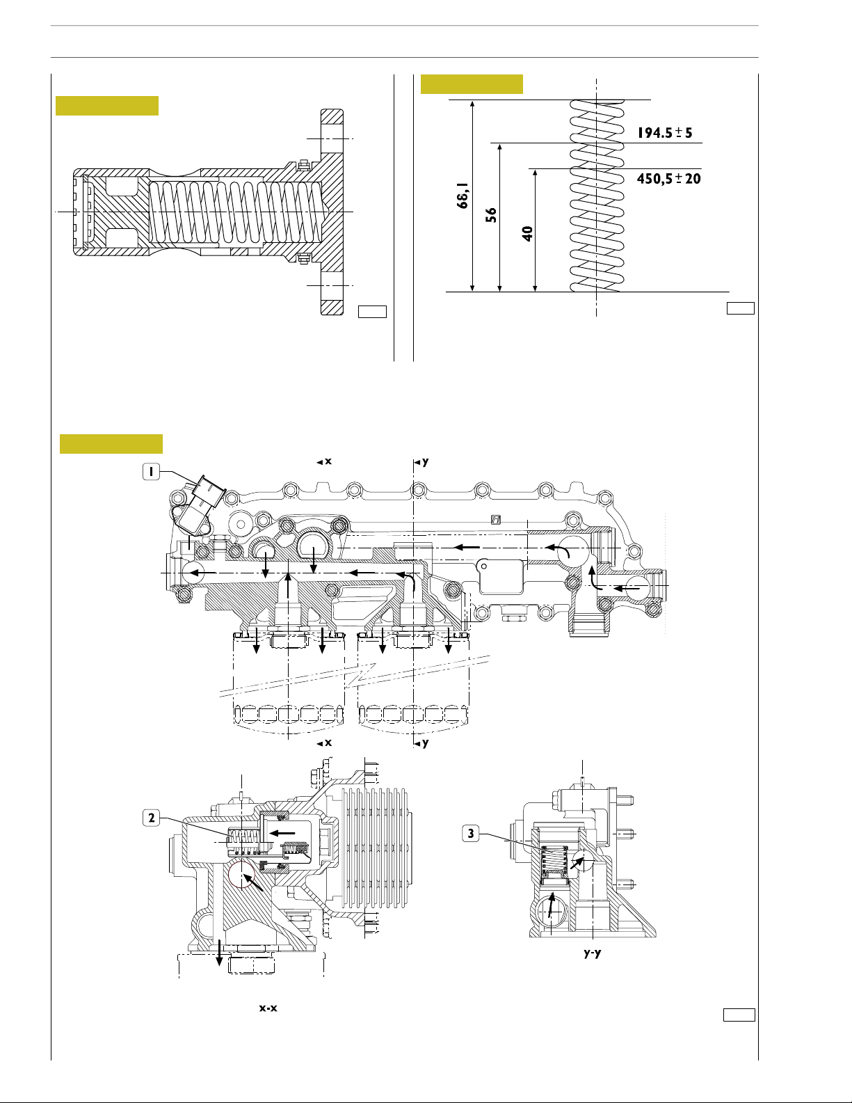
Figure 23
60560
The oil pump (1) cannot be overhauled. On finding any
damage, replace the oil pump assembly.
See under the relevant heading for replacing the gear (2) of
the crankshaft.
Overpressure valve
Figure 25
73540
MAIN DATA TO CHECK THE OVERPRESSURE
VALVE SPRING
Figure 24
1
OIL PUMP CROSS-SECTION
1. Overpressure valve — Start of opening pressure 10.1 ±0.7 bars.
73541
Base - May 2007Print P2D32C003 E
Page 36
20
SECTION 1 - GENERAL SPECIFICATIONS
CURSOR ENGINES F3A
Oil pressure control valve
Figure 27
Figure 26
73542
The oil pressure co ntrol valve is located on the left-hand side
of the c rankcase.
MAIN DATA TO CHECK THE OIL PRESSURE
CONTROL VALVE SPRING
73543
Start of opening pressure 5 bars.
Heat exchanger
(for type: F3AE0684P*E906 - F3AE0684L*E906 - F3AE0684P*E905 - F3AE0684N*E907 F3AE9687A*E001 - F3AE9687B*E001 - F3AE9687C*E001)
Figure 28
104236
HEAT EXCHANGER
The heat exchan ger is fitted with: 1. Oil pressure/temperature sensor - 2. By-pass valve - 3. Heat valve.
Base - May 2007 Print P2D32C003 E
Page 37

CURSOR ENGINES F3A
Heat exchanger (only for type: F3AE0684P*E904)
Figure 29
2
SECTION 1 - GENERAL SPECIFICATIONS
21
104237
HEAT EXCHANGER
The following elements are fitted on the intercooler: 1. By-pass valve - 2. Oil pressure/temperature sensor - 3. Heat valve.
Base - May 2007Print P2D32C003 E
Page 38

22
SECTION 1 - GENERAL SPECIFICATIONS
CURSOR ENGINES F3A
By-pass valve
Figure 30
The valve quickly o pens at a pressure of: 3 bars.
Thermostatic valve
Figure 31
73545
This is a new generation of filters that permit much more
thorough filtration as they are able to holder back a great er
amount of particles of smaller dimensions than those held
back by conventional filters with a paper filtering element.
These high-filtration devices, to date used only in industrial
processes, make it possible to:
- reduce the wear of engine components over time;
- maintain the performance/specifications of the oil and
thereby lengthen the time intervals between changes.
External spiral winding
The filtering elements are closely wound by a spiral so that
each fold is firmly anchored to the spiral with respect to the
others. This produces a uniform use of the element even in
the worst conditions such as cold starting with fluids with a
high viscosity and peaks of flow. In addition, it ensures uniform distribution of the flow over the entire length of the
filtering element, with consequent optimization of the loss of
load and of its working life.
Mount upstream
To optimize flow distribution and the rigidity of the filtering element, this has an exclusive mount composed of a strong mesh
made of nylon and an extremely strong synthetic material.
Start of opening:
- travel 0.1 mm at a temperature of 82 ±2°C
End of opening:
- travel 8 mm at a temperature of 97°C
.
Engine oil filters
Figure 32
Filtering element
73546
Composed of inert inorganic fibres bound with an exclusive
resin to a structure with graded holes, the element is manu-
.
factured exclusively to precise procedures and strict quality
control.
Mount downstream
A mount for the filtering element and a strong nylon mesh
make it even stronger, which is especially helpful during cold
starts and long periods of use. The performance of the filter
remains constant and reliable throughout its working life and
from one element to another, irrespective of the changes in
working conditions.
Structural parts
The o-rings equipping the filtering element ensure a perfect
seal between it and the container, eliminating by-pass risks
and keeping filter performance constant. Strong corrosionproof bottoms and a sturdy internal metal core complete the
structure of the filtering element.
When mounting the filters, keep to the following rules:
- Oil and fit new seals.
- Screw down the filters to bring the seals into contact
with the supporting bases.
- Tighten the filter to a torque of 35-40 Nm.
47447
Base - May 2007 Print P2D32C003 E
Page 39

CURSOR ENGINES F3A
SECTION 1 - GENERAL SPECIFICATIONS
COOLING
Description
The engine cooling system is of the closed-circuit, forced circulation type.
It consists mainly of the following components:
- expansion tank, not supplied;
- a heat exchanger to cool down lubrication oil;
- a water pump with centrifugal system incorporated in the cylinder block;
- fan, not supplied;
- a 2-way thermostat controlling t h e coolant circulation.
Operation
The water pump is actuated by the crankshaft through a poli-V belt and sends coolant to t he cylinder block, especially to the
cylinder head (bigger quantity). When the coolant temperature reaches and overcomes the operating temperature, the
thermostat is opened and from here the coolant flows into the radiator and is cooled down by the fan.
The pressure inside the system, due to temperature change, is adequately controlled t hrough t he expansion vessel.
23
Base - May 2007Print P2D32C003 E
Page 40

24
SECTION 1 - GENERAL SPECIFICATIONS
Figure 33
CURSOR ENGINES F3A
Water flowing out of the thermostat
Water circulating in the engine
Water flowing into the pump
104238
Base - May 2007 Print P2D32C003 E
Page 41

CURSOR ENGINES F3A
SECTION 1 - GENERAL SPECIFICATIONS
25
Water pump
Figure 34
104239
CROSS-SECTION OF THE WATER PUMP
The water pump consists of: rotor, shaft with bearing,
T-gasket and drive pulley with dust sh ield.
Figure 36
TO THE
RADIATOR
TO THE
EXPANSION
TUB
TO THE
FROM
THE ENGINE
BY PASS
60748
Water leaving the thermostat
Check the t hermostat works properly; replace it if in doubt.
Temperature of start of travel 84°C ±2°C.
Minimumtravel15mmat94°C ±2°C.
Check that the pump body has no cracks or water
leakage; if it does, replace the entire water pump.
Thermostat
View of thermostat operation
Figure 35
TO THE
RADIATOR
TO THE
EXPANSION
TUB
FROM
THE ENGINE
Water circulating in the engine
TO THE
BY PASS
60747
Base - May 2007Print P2D32C003 E
Page 42

26
SECTION 1 - GENERAL SPECIFICATIONS
TURBOCHARGING
The turbocharging system consists of:
- air filter;
- Wastegate turbocharger.
Figure 37
CURSOR ENGINES F3A
1. TURBOCHARGER HX55
Exhaust gas
Inlet air
Compressed air (hot )
Intake compressed air
104240
Base - May 2007 Print P2D32C003 E
Page 43

CURSOR ENGINES F3A
SECTION 1 - GENERAL SPECIFICATIONS
EGR EXHAUST GAS RECIRCULATION SYSTEM
The exhaust gases may be partially conveyed back into the cylinders to reduce the maximum combustion temperature responsible for producing nitrogen oxides (NOx).
The exhaust gas recirculation (EGR) system, by reducing the combustion temperature, thus represents an effective NOx emission controlling system.
INTERNAL EGR ACTING ON THE INTAKE VALVES
Through a modification to the design of the intake cams, the internal EGR system enables part of the exhaust gas to be conveyed
back into the engine’s cylinders.
This type of EGR, called internal EGR, has n o electronically controlled elements, the system is always active.
Its configuration requires no additional elements such as control valves, pipes or heat exchangers, so the profile of the engine
remains unchanged.
In addition to the main lobe, the intake cam presents an additional lobe (3) with respect to the configuration without EGR.
During the exhaust stroke of the cylinder concerned, this lobe opens the intake valve slightly earlier (*). In this way, part of the
exhaust gas is trapped in the intake pipe and then, during the int ake stroke of the cylinder, is returned to the load of the cy linder
forthepowerstroke.
Figure 38
27
Y: Lift of valves in mm.
Y: Regulation of engine
shaft in degrees
1. Exhaust cams - 2. Intake cams - 3. EGR lobe - S. Exhaust pipes - A. Intake pipes.
104761
Base - May 2007Print P2D32C003 E
Page 44

28
SECTION 1 - GENERAL SPECIFICATIONS
CURSOR ENGINES F3A
Base - May 2007 Print P2D32C003 E
Page 45

CURSOR ENGINES F3A
SECTION 2- FUEL
SECTION 2
Fuel
FEEDING 3...............................
FUEL SUPPLY DIAGRAM (ALL TYPES) 4.......
- Fuel pump 5............................
- Injector-pump 5.........................
1
Page
Base - May 2007Print P2D32C003 E
Page 46

2
SECTION 2 - FUEL
CURSOR ENGINES F3A
Base - May 2007 Print P2D32C003 E
Page 47

CURSOR ENGINES F3A
FEEDING
Fuel is supplied via a fuel pump, filter and pre-filter, 6
pump-injectors govern ed by the camshaft via rocker arms
and by the electronic control unit.
Figure 1
SECTION 2- FUEL
3
1. Fuel pressure damper - 2. Valve for return circuit, starts opening at 3.5 bars -
3. Valve for return circuit, starts opening at 0.2 bars.
Return circuit
Supply circuit
104241
Base - May 2007Print P2D32C003 E
Page 48

4
SECTION 2 - FUEL
FUEL SUPPLY DIAGRAM (ALL TYPES)
Figure 2
CURSOR ENGINES F3A
104242
1. Temperature sensor - 2. Bleed valve - 3. Secondary fuel filter - 4. By-pass valve (0.3 ÷ 0.4 bar) - 5. Fuel su pply pump -
6. Integrated valve (3.5 bar) - 7. Pressure relief valve (5 bar) - 8. Fuel tan k - 9. Priming pump - 10. Primary fuel filter -
11. Check valve (opening 0.1 bar) - 12. Heater - 13. Electronic control unit - 14. Fuel return union with valve built in
(0.2 bar) - 15. Pump-inject ors.
Base - May 2007 Print P2D32C003 E
Page 49

CURSOR ENGINES F3A
SECTION 2- FUEL
5
Fuel pump
Figure 3
A. Fuel inlet — B. Fuel delivery — C. By-pass nut —
D. Fuel return from the pump-injectors —
E. Pressure relief valve — Opening pressure: 5-8 bars.
Figure 4
CROSS-SECTION OF THE FUEL PUMP
1. Oil and fuel leakage indicator.
Injector-pump
73547
73548
Pumping element
The pumping element is operated by a rocker arm governed
directly by the cam of the camshaft.
The pumping element is able to ensure a high delivery
pressure. The return stroke is made by means of a return
spring.
Nozzle
Garages are authorized to perform fault diagnosis solely on
the entire injection system and may not work inside the
injector-pump, which must only be replaced.
A specific fault-diagnosis program, included in the control
unit, is able to check the operation of each injector (it
deactivates one at a time and checks the delivery of the other
five).
Fault diagnosis makes it possible to distinguish errors of an
electrical origin from ones of a mechanical/hydraulic origin.
It indicates broken pump-injectors.
It is therefore n ecessary to interpret all the control unit error
messages correctly.
Any defects in the injectors are to be resolved by replacing
them.
Solenoid valve
The solenoid, which is energized at each active phase of the
cycle, via a signal from the control unit, controls a slide valve
that shuts off the pumping element delivery pipe.
When the solenoid is not energized, the valve is open, the
fuel is pumped but it flows back into th e return pipe with the
normal transfer pressure of approximately 5 bars.
When the solenoid is energized, the valve shuts and the fuel,
not being able to flow back into the return pipe, is pumped
into the nozzle at high pressure, causing the needle to lift.
The amount of fuel injected depends on the length of time
the slide valve is closed and therefore on the time for which
the solenoid is energized.
The solenoid valve is joined to the injector body and cannot
be removed.
On the top there are two screws securing the electrical
wiring from the c ontrol unit.
To ensure signal transmission, tighten the screws with a torque
wrenchtoatorqueof1.36—1.92Nm(0.136—0.192kgm).
Figure 5
104243
1. Fuel/oil seal — 2. Fuel/diesel seal — 3. Fuel/exhaust gas seal.
The injector-pump is composed of: pumping element, nozzle,
solenoid valve.
Base - May 2007Print P2D32C003 E
Page 50
6
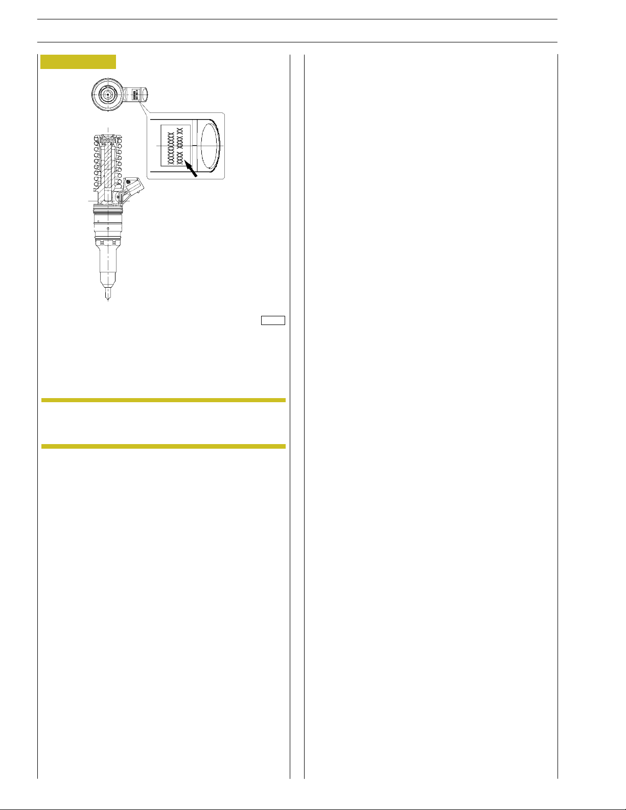
Figure 6
SECTION 2 - FUEL
CURSOR ENGINES F3A
104245
Foreachinjectorreplaced,hook up to the diagnostic station
and, when asked by the program, enter the code punchedon
the injector (→) to reprogram the control unit.
NOTE
When checking the clearance of the rocker arms,
it is important to check the injector-pump pre-load.
Base - May 2007 Print P2D32C003 E
Page 51

CURSOR ENGINES F3A
SECTION 3 - INDUSTRIAL APPLICATION
SECTION 3
Industrial application
CLEARANCE DATA 3.....................
PART ONE -
MECHANICAL COMPONENTS 5.........
ENGINE DISASSEMBLY ASSEMBLY 7.........
ENGINE ASSEMBLY 14......................
ENGINE FLYWHEEL 16.....................
- Fitting engine flywheel 16...................
- Fitting camshaft 17........................
- Fitting pump-injectors 18...................
- Fitting rocker-arm shaft assembly 18..........
1
Page
- Camshaft timing 19.......................
- Phonic wheel timing 21....................
- Intake and exhaust rocker play adjustment and
pre-loading of rockers controlling pump injectors 22
ENGINE COMPLETION 23..................
PART TWO -
ELECTRICAL EQUIPMENT 29.............
- Components on the engine F3A
(For all types except F3AE0684P*E904) 31.....
- Components on the engine F3A
(only for type F3AE0684P*E904) 32..........
- Components on the engine F3A
(only for type F3AE0684N*E907) 33.........
- Components on the engine F3A
(only for type F3AE9687A*E001) 34..........
BLOCK DIAGRAM 35.......................
- EDC 7 UC31 electronic control unit 36.......
- EDC control unit PIN-OUT 37..............
- Pump injector 40.........................
- Engine coolant temperature sensor 41........
- Fuel temperature sensor 42.................
- Flywheel pulse transmitter 43................
- Distribution pulse transmitter 44.............
Base - May 2007Print P2D32C003 E
Page 52

2
SECTION 3 - INDUSTRIAL APPLICATION
-Sensor de temperatura/presión del aire 45.....
-Sensor de presión/temperatura de aceite 45....
-Alt ernator 46............................
-Starting motor 47.........................
-Pre/post-heating resistance 48...............
EDC SYSTEM FUNCTIONS 49................
PART THREE - TROUBLESHOOTING 53......
PREFACE 55...............................
METHODS OF DIAGNOSIS 56...............
-PT-01 56...............................
PT-01 PORTABLE TESTER 57.................
CURSOR ENGINES F3A
Page
-Main functions 57.........................
-Test parameters 57.......................
FAILURE CODES 58........................
Base - May 2007 Print P2D32C003 E
Page 53

CURSOR ENGINES F3A
Typ
e
CLEARANCE DATA
SECTION 3 - INDUSTRIAL APPLICATION 3
F3AE0684
P*E904 P*E906 L*E906 P*E905 N*E907
bar
ρ
Compression ratio 16.5:1
Max. output kW
(HP)
rpm
Max. torque Nm
(kgm)
rpm
Loadless engine
idling rpm
Loadless engine
peak rpm
Borexstroke mm
Displacement cm
SUPERCHARGING
Turbocharger type
LUBRICATION
Oil pressure
(warm engine)
317
(430)
2100
1900
(190)
1500
1000 1000 1000 1000 600
2110 2110 2110 2110 2110
3
317
(430)
2100
1900
(190)
1500
Forced by gear pump, relief valve single action
335
(455)
2100
1900
(190)
1500
125 x 140
10300
Intercooler
Direct injection
HOLSET HX55
oil filter
317
(430)
2100
1900
(190)
1500
291
(395)
2100
1820
(182)
1500
NOTE
- idling bar
- peak rpm bar
COOLING
Water pump control
Thermostat
- start of opening ºC
Data, features and performances are valid only if the setter fully complies with all the installation prescriptions provided
by FPT.
Furthermore, the users assembled by the setter shall always be in conformance to couple, power and number of turns
based on which the engine has been designed.
By means of belt
-
-
Liquid
-
Base - May 2007Print P2D32C003 E
Page 54

4
Typ
e
SECTION 3 - INDUSTRIAL APPLICATION
CLEARANCE DATA
CURSOR ENGINES F3A
F3AE9687
A*E001 B*E001 C*E001
bar
ρ
Compression ratio 16.5:1
Max. output kW
(HP)
rpm
Max. torque Nm
(kgm)
rpm
Loadless engine
idling rpm
Loadless engine
peak rpm
Borexstroke mm
Displacement cm
SUPERCHARGING
Turbocharger type
LUBRICATION
Oil pressure
(warm engine)
315
(428)
2100
1900
(190)
1500
800 800 800
2300 2300 2300
3
DIRECT INJECTION INTERCOOLER
Forced by gear pump, relief valve single action
290
(394)
2100
1800
(180)
1500
125 x 140
10300
HOLSET HX55
oil filter
265
(360)
2100
1700
(170)
1500
NOTE
- idling bar
- peak rpm bar
COOLING
Water pump control
Thermostat
- start of opening ºC
Data, features and performances are valid only if the setter fully complies with all the installation prescriptions provided
by FPT.
Furthermore, the users assembled by the setter shall always be in conformance to couple, power and number of turns
based on which the engine has been designed.
By means of belt
-
-
Liquid
-
Base - May 2007 Print P2D32C003 E
Page 55

CURSOR ENGINES F3A
SECTION 3 - INDUSTRIAL APPLICATION 5
PART ONE -
MECHANICAL COMPONENTS
Base - May 2007Print P2D32C003 E
Page 56

6
SECTION 3 - INDUSTRIAL APPLICATION
CURSOR ENGINES F3A
Base - May 2007 Print P2D32C003 E
Page 57

CURSOR ENGINES F3A
SECTION 3 - INDUSTRIAL APPLICATION 7
ENGINE DISASSEMBLY ASSEMBLY
Handle all parts extremely carefully. Never get your
hands or fingers between pieces.
Wear the required safety clothing such as goggles,
gloves and safety shoes.
Protect the electric parts before doing any washing with
high-pressure jets.
Figure 1
Figure 3
104247
- Remove the engine supports;
- removethedrive(1).
99357
Before securing the engine on the rotary stand, remove:
- the engine electric cable, disconnecting it from the control
unit and from all the sensors/transmitters connected to it;
For all types except F3AE0684P*E904 and F3AE0684N*E907.
- using a suitable tool (3), work in the direction of the arrow
on the tightener and remove the compressor drive belt
(1);
- remove the compressor (2) together with the engine
support.
Figure 2
Figure 4
- Remove the oil pressure adjuster valve (1).
104246
104248
- Secure the engine to the rotary stand with the brackets
993601036.
- Drain the lubricating oil from the sump.
Base - May 2007Print P2D32C003 E
Page 58

8
SECTION 3 - INDUSTRIAL APPLICATION
CURSOR ENGINES F3A
Figure 5
104249
For all types excluding F3AE0684P*E904
- Using a suitabletool (3), work in the direction of the arrow
on the tightener (2) and remove the belt (1).
Figure 6
Figure 8
104251
Remove:
- thermostat assembly (8);
- pipes complete with coolant (6);
- pulley (4);
- water pump (7);
- automatic tightener support (1);
- fixed tightener ( 5);
- damper flywheel (3) and pulley beneath;
- automatic tightener (2);
104250
Only for type F3AE0684P*E904
- Using a suitable tool, operate on the belt take-up units (1)
and (3) in order to remove the belts (2) and (4).
- Remove the compressor (5) and the fan hub (6) with
related supports.
Figure 7
104249/A
Remove:
-alternator(2).
- supports (1 and 3).
Figure 9
99361
with the extractor 99340053 (2) applied as shown in the
figure, extract the seal (4). Undo the screws (3) and take off
the cover (1). Disconnect all the electrical connections and
sensors.
Base - May 2007 Print P2D32C003 E
Page 59

CURSOR ENGINES F3A
SECTION 3 - INDUSTRIAL APPLICATION 9
Figure 10
1
2
On the engine exhaust side, remove the following parts:
- oil delivery pipe (1);
- oil return pipe (4);
- turbocharger (3);
- exhaust manifold (2).
3
4
104252
Figure 12
101960
- using tool 99360314 unscrew the oil filters (1).
Figure 11
99258
Only for type F3AE0684P*E904
- disconnect the oil pipes (3) and (4) and disengage them
from the clamps (←);
- take out the fixing screws (1) and remove the cooler (2);
Figure 13
99362
- Disconnect the pipes (2) from the support (1) disengaging
them from the clamps and remove them.
- Take out the screws (3) and remove the supports (1).
Base - May 2007Print P2D32C003 E
Page 60

10
SECTION 3 - INDUSTRIAL APPLICATION
CURSOR ENGINES F3A
Figure 14
104306
For all types excluding F3AE0684P*E904 only, using tool
99360314 (2), unscrew the oil filters (1).
Figure 16
104253
For all types except F3AE0684N*E907.
Take out the screws (2) and remove the intake manifold (1).
Figure 17
Figure 15
Disconnect the fuel pipes (1) from the fuel pump (2).
Remove:
- the fuel pump (2);
- the fuel filter unit (3) and pipes (1).
104254
Only for type F3AE0684N*E907
104763
Loosen the screws (1) and remove the intake manifold (2).
Figure 18
Remove:
104255
- the starter motor (1);
- the control unit (2) and its support;
- the oil dipstick (3) from the crankcase.
Base - May 2007 Print P2D32C003 E
Page 61

CURSOR ENGINES F3A
SECTION 3 - INDUSTRIAL APPLICATION 11
Figure 19
104256
- Unscrew the screws (1) and remove the heat exchanger (4);
- unscrew the screws (2) and remove the water line (3).
Figure 21
60496
- Unscrew the screws (2) and remove the gear (1) fitted
with phonic wheel.
Figure 20
85480
Remove the rocker arm cover (1), take off the screws (2) and
remove: the cover (3), the filter (5) and the gaskets (4 and 6).
Take off the screws (8) and remove the blow-by case (7).
Figure 22
60497
- Unscrew the screws (1); tighten one screw in a reaction
hole and remove the shoulder plate (2), remove the sheet
gasket.
Base - May 2007Print P2D32C003 E
Page 62

12
SECTION 3 - INDUSTRIAL APPLICATION
CURSOR ENGINES F3A
Figure 23
60498
Unscrew the screws (2) and remove the transmission gear (1).
Figure 24
Figure 26
60501
Unscrew the screws (1) and take down the gearbox (2).
Figure 27
60499
Stop the engine flywheel (3) rotation by means of tool
99360351 (1), unscrew the fixing screws (2) and remove the
engine flywheel.
Figure 25
60500
Apply the extractor 99340054 (2) and pull out the seal
gasket (1).
99364
In sequence, take out the:
- idle gear (1);
- oil pump gear (2).
Figure 28
104257
- Disconnect the electrical connections from the pump
injectors from the pump injector solenoid valves.
- Unscrew the screws (1) fixing the rocker arm shaft.
Base - May 2007 Print P2D32C003 E
Page 63

CURSOR ENGINES F3A
SECTION 3 - INDUSTRIAL APPLICATION 13
Figure 29
116814
Apply tool 99360553 (1) to the rocker holder shaft (2) and
remove the shaft (2) from the cylinder head.
Figure 30
Figure 32
60515
- By means of metal ropes, lift the cylinder head (1).
- Remove the seal (2).
Figure 33
102935
To extract pump injector from cylinder head, use the tool
operating as follows:
- hook tool 99342149 part (3) to pump injector (4);
- mount part (2) on part (3) resting part (2) on cylinder
head;
- screw nut (1) and extract pump injector (4) from cylinder
head.
Figure 31
60514
- Fit the plugs 99360180 (1) instead of injectors.
- Remove the camshaft (2).
- Unscrew the fixing screws on the cylinder head (3).
99268
For all types except F3AE0684P*E904 and F3AE0684N*E907
Undo the screws (2) and remove the engine oil sump (1)
together with the spacer ( 3) and the seal (4).
Figure 34
81871
Only valid for types F3AE0684P*E904 - F3AE0684N*E907 F3AE9687A*E001 - F3AE9687B*E001 - F3AE9687C*E001.
Base - May 2007Print P2D32C003 E
Page 64

14
SECTION 3 - INDUSTRIAL APPLICATION
CURSOR ENGINES F3A
Figure 35
Undo the screws and remove the suction strainer (1).
A. F3AE0684P*E904 - F3AE0684N*E907 -
F3AE9687A*E001 - F3AE9687B*E001 F3AE9687C*E001
B. F3AE0684P*E906 - F3AE0684L*E906
F3AE0684P*E905 - F3AE0684N*E907.
99367
Figure 38
60515
Check that the pistons 1-6 are exactly at the T.D.C.
Put the gasket (2) on the crankcase.
Mount the cylinder head (1) and tighten the screws as shown
in Figs. 38 - 39 - 40.
NOTE
Lubricate the thread of the screws with engine oil
before assembly.
Use new screws every time for head assembly.
ENGINE ASSEMBLY
Figure 36
60563
Using the centring ring 99396035 (2), check the exact position
of the cover (1). If it is wrong, proceed accordingly and lock
the screws (3).
Figure 37
Figure 39
61270
Diagram of the tightening sequence of the screws fixing the
cylinder head.
Figure 40
60564
Key on the gasket (1), mount the key 99346250 (2) and,
screwing down the nut (3), drive in the gasket (1).
Base - May 2007 Print P2D32C003 E
- Pre-tightening with the torque wrench (1):
st
phase: 60 Nm (6 kgm).
1
nd
phase: 120 Nm (12 kgm).
2
60565
Page 65

CURSOR ENGINES F3A
SECTION 3 - INDUSTRIAL APPLICATION 15
Figure 41
α
- Closing to angle with tool 99395216 (1):
rd
3
phase: angle of 120°.
th
phase: angle of 60°.
4
Figure 42
α
60566
NOTE
Figure 44
Mount the gear housing within 10 min. of applying
the sealant.
60567
Mount the oil pump (4), the intermediate gears (2) together
with the link rod (1) and lock the screws (3) in two phases:
pre-tightening 30 Nm.
closing to angle 90°.
Figure 43
60633
Using a torque wrench, tighten the highlighted screws with the
following sequence and tightening torques:
10 screws M12 x 1.75 x 100 63 Nm
2 screws M12 x 1.75 x 70 63 Nm
4 screws M12 x 1.75 x 35 63 Nm
1 screw M12 x 1.75 x 120 63 Nm
2 screws M12 x 1.75 x 193 63 Nm
:
Figure 45
47592
Apply LOCTITE5970 IVECO n˚ 2992644 silicone on the gear
housing, using appropriate tools (1), as shown in the figure.
The sealer string (1) diameter is to be 1,5 ±
0.5
0.2
60568
Key on the gasket (1), mount the keying device 99346251 (2)
and, screwing down the nut (3), drive i n the gasket.
Base - May 2007Print P2D32C003 E
Page 66

16
SECTION 3 - INDUSTRIAL APPLICATION
CURSOR ENGINES F3A
ENGINE FLYWHEEL
Fitting engine flywheel (For types: F3AE0684P*E904 - F 3AE0684P*E906 - F 3AE0684L*E906)
Figure 46
VIEW OF HOLES:
A—B—C
VIEW OF HOLE:
D
60668
DETAIL OF PUNCH MARKS ON ENGINE FLYWHEEL FOR PISTON POSITIONS
A = Hole on flywheel with one reference mark,
corresponding to the TDC of pistons 3-4.
B = Hole on flywheel with one reference mark,
corresponding to the TDC of pistons 1-6.
C = Hole on flywheel with one reference mark,
corresponding to the TDC of pistons 2-5.
D = Hole on flywheel with two reference marks, position
corresponding to 54°.
Fitting engines flywheel (Only for type: F3AE0684N*E907 - F3AE9687A*E001 - F3AE9687B*E001 F3AE9687C*E001)
Figure 47
104764
DETAIL OF PUNCH MARKS ON ENGINE FLYWHEEL FOR PISTON POSITIONS
A = Hole on flywheel with one reference mark,
corresponding to the TDC of pistons 3-4.
B = Hole on flywheel with one reference mark,
corresponding to the TDC of pistons 1-6.
Base - May 2007 Print P2D32C003 E
C = Hole on flywheel with one reference mark,
corresponding to the TDC of pistons 2-5.
D = Hole on flywheel with two reference marks, position
corresponding to 54°.
Page 67

CURSOR ENGINES F3A
If the teeth of the ring gear mounted on the engine
flywheel, for starting the engine, are very damaged,
replace the ring gear. It must be fitted after heatingthe
ring gear to a temperature of approx. 200°C.
Figure 48
α
SECTION 3 - INDUSTRIAL APPLICATION 17
Fitting camshaft
Figure 50
49037
NOTE
The crankshaft has a locating peg that has to couple
with the relevant seat on the engine flywheel.
Position the flywheel (1) on the crankshaft, lubricate the
thread of the screws (2) with engine oil and screw them down.
Lock rotation with tool 99360351 (3). Lock the screws (2) in
three phases.
First phase: pre-tightening with torque wrench (4) to a torque
of 120 Nm (12 kgm).
Figure 49
Position the crankshaft with the pistons 1 and 6 at the top dead
72436
centre (T.D.C.).
This situation occurs when:
1. The hole with reference mark (5) of the engine flywheel
(4) can be seen through the inspection window.
2. The tool 99360612 (1), through the seat (2) of the engine
speed sensor, enters the hole (3) in the engine flywheel (4).
If this condition does not occur, turn the engine flywheel (4)
appropriately. Remove the tool 99360612 (1).
Figure 51
73843
Fit the camshaft (4), positioning it observing the reference
marks (→) as shown in the figure.
Lubricate the seal (3) and fit it on the shoulder plate (2).
Mount the shoulder plate (2) with the sheet metal gasket (1)
and tighten the screws (5) to the required torque.
α
49036
Second and third phase: closing to angle of 60° +30° with tool
99395216 (1).
Figure 52
60570
- Apply the gauge 99395218 (1). Check and adjust the
position of the link rod (3) for the idle gear. Lock the screw
(2) to the required torque.
Base - May 2007Print P2D32C003 E
Page 68

18
SECTION 3 - INDUSTRIAL APPLICATION
CURSOR ENGINES F3A
Figure 53
60571
- Fit the idle gear (1) back on and lock the screws (2) to the
required torque.
Fitting pump-injectors
Figure 55
104243
Fit the seals (1) (2) (3) on the injectors.
Figure 56
Figure 54
5
60572
Position the gear (2) on the camshaft so that the 4 slots are
centred with the holes for fixing the camshaft, without fully
locking the screws (5).
Using the dial gauge with a magnetic base (1), check that the
clearance between the gears (2 and 3) is 0.073 — 0.195 mm;
if this is not so, adjust the clearance as follows:
- Loosen the screws (4) fixing the idle gear (3).
- Loosen the screw (2, Figure 52) fixing the link rod. Shift
the link rod (3, Figure 52) to obtain the required
clearance.
- Lock the screw (2, Figure 52) fixing the link rod and
screws (2, Figure 53) fixing the idle gear to the required
torque.
Mount:
104260
- The injectors (1) and, using a torque wrench, lock the
bracket fixing screws to a torque of 26 Nm.
- The crosspieces (2) on the valve stem, all with the largest
holeonthesameside.
Fitting rocker-arm shaft assembly
Figure 57
NOTE
Apply the tool 99360553 (1) to the rocker arm shaft (2) and
mount the shaft on the cylinder head.
Before refitting the rocker-arm shaft assembly,
make sure that all the adjustment screws have been
fully unscrewed.
116814
Base - May 2007 Print P2D32C003 E
Page 69

CURSOR ENGINES F3A
SECTION 3 - INDUSTRIAL APPLICATION 19
Figure 58
70567A
SCHEME OF SCREW TIGHTENING SEQUENCE
SECURING ROCKER ARMS
Screw screws (1 - 2 - 3) until rocker arms are brought to
contact relating seats on cylinder head, tighten the screws
according to sequence indicated in figure operating in two
steps as indicated in successive figure.
Camshaft timing
Figure 60
71776
Figure 59
α
104261
Apply the tool 99360321 (7) and the spacer 99360325 (6) to
the gearbox (3).
NOTE
The arrow shows the direction of rotation of the
engine when running.
Using the above-mentioned tool, turn the engine
flywheel (1) in the direction of rotation of the
engine so as to take the piston of cylinder no.1 to
approximately the T.D.C. in the phase of
combustion.
This condition occurs when the hole with one
reference mark (4), after the hole with two
reference marks (5) on the engine flywheel (1), can
be seen through the inspection window (2).
Lock the screws (2) fixing the rocker-arm shaft as follows:
st
- 1
- 2
phase: tightening to a torque of 80 Nm (8 kgm) with
thetorquewrench(1);
nd
phase: closing with an angle of 60° using the tool
99395216 (3).
Fit and connect the wiring to the injectors.
Base - May 2007Print P2D32C003 E
Page 70

20
SECTION 3 - INDUSTRIAL APPLICATION
CURSOR ENGINES F3A
Figure 61
71774
The exact position of piston no.1 at the T.D.C. is obtained
when in the above-described conditions the tool 99360612
(1) goes through the seat (2) of the engine speed sensor into
thehole(3)intheengineflywheel(4).
If this is not the case, turn and adjust the engine flywheel (4)
appropriately.
Remove the tool 99360612 (1).
Figure 63
77259
The camshaft is in step if at the cam lift values of 4.44 ±0.05 mm
there are the following conditions:
1) theholemarkedwithanotch(5)canbeseenthroughthe
inspection window;
2) the tool 99360612 (1) through the seat (2) of the engine
speed sensor goes into the hole (3) in the engine
flywheel (4).
Figure 62
60573
Set the dial gauge with the magnetic base (1) with the rod on
the roller (2) of the rocker arm that governs the injector of
cylinder no.1 and pre-load it by 6 mm.
With tool 99360321 (7) Figure 60, turn the crankshaft
clockwise until the pointer of the dial gauge reaches the
minimum value beyond which it can no longer fall.
Reset the dial gauge.
Turn the engine flywheel anticlockwise until the dial gauge gives
a reading for the lift of the cam of the camshaft of 4.44 ±0.05 mm.
Figure 64
60575
If you do not obtain the conditions illustrated in Figure 63 and
described in points 1 and 2, proceed as follows:
1) loosen the screws (2) securing the gear (1) to the camshaft
and utilize the slots (see Figure 65) on the gear (1);
2) turn the engine flywheel appropriately so as to bring about
the conditions described in points 1 and 2 Figure 63, it
being understood that the cam lift must not change at all;
3) lock the screws (2) and repeat the check as described
above.
Tighten the screws (2) to the required torque.
Base - May 2007 Print P2D32C003 E
Page 71

CURSOR ENGINES F3A
SECTION 3 - INDUSTRIAL APPLICATION 21
Figure 65
71778
When the adjustment with the slots (1) is not enough to make
up the phase difference and the camshaft turns because it
becomes integral with the gear (2); as a result, the reference
value of the cam lift varies, in this situation it is necessary to
proceed as follows:
1) lock the screws (2, Figure 64) and turn the engine flywheel
clockwise by approx. 1/2 turn;
2) turn the engine flywheel anticlockwise until the dial gauge
gives a reading of the lift of the cam of the camshaft of 4.44
±0.05 mm;
3) take out the screws (2, Figure 64) and remove the gear (1)
from the camshaft.
Mount the gear (2) Figure 65 with the 4 slots (1) centred with
the fixing holes of the camshaft, locking the relevant screws to
the required tightening torque.
Check the timing of the shaft by first turning the flywheel
clockwise to discharge the cylinder completely and then turn
the flywheel anticlockwise until the dial gauge gives a reading
of 4.44 ±0.05.
Check the timing conditions described in Figure 63.
Phonic wheel timing
Figure 67
Figure 66
72436
Turn the flywheel (4) again to bring about the following
conditions:
- a notch (5) can be seen through the inspection window;
- the tool 99360612 (1) inserted to the bottom of the seat
of the engine speed sensor (2) and (3).
77260
Turn the crankshaft by taking the piston of cylinder no. 1 into
the compression phase at T .D.C.; turn the fly wheel in the
opposite direction to the normal direction of rotation by
approximately 1/4 of a turn.
Again turn the flywheel in its normal direction of rotation until
you see the hole marked with the double notch (4) through
the inspection hole under the flywheel housing. Insert tool
99360612 (5) into the seat of the flywheel sensor (6).
Insert the tool 99360613 (2), via the seat of the phase sensor,
onto the tooth obtained on the phonic wheel.
Should inserting the tool (2) prove difficult, loosen the screws
(3) and adjust the phonic wheel (1) appropriately so that the
tool (2) gets positioned on the tooth c orrectly. Go ahead and
tighten the screws (3).
Base - May 2007Print P2D32C003 E
Page 72

22
g
pumpinj
SECTION 3 - INDUSTRIAL APPLICATION
CURSOR ENGINES F3A
Intake and exhaust rockerplay adjustment andpre-loadingofrockers controllin
Figure 68
ectors
ADJUSTMENT OF INTAKE, EXHAUST AND INJECTION ROCKERS
The adjustment of clearance between the rockers and rods
controlling the intake and exhaust valves, as well as the
adjustment of pre-loading of the rockers controlling pump
injectors, must be carried out carefully.
Take the cylinder where clearance must be adjusted to the
bursting phase; its valves are closed while balancing the
symmetric cylinder valves.
Symmetric cylinders are 1-6, 2-5 and 3-4.
In order to properly operate, follow these instructions and
data specified on the table.
Adjustment of clearance between the rockers and
controlling intake and exhaust
valves:
rods
- use a polygonal wrench to slacken the locking nut (1) of
the rocker arm adjusting screw (2).
- insert the thickness gauge blade (3);
- tighten or untighten the adjustment screw with the
appropriate wrench;
- make sure that the gauge blade (3) can slide with a slight
friction;
- lock the nut (1), by blocking the adjustment screw.
Pre-loading of rockers controlling pump
injectors:
- using a polygonal wrench, l oosen the nut locking the
rocker adjustment screw (5) controlling the pump
injector (6);
104262
- using an appropriate wrench(4), loosenthe adjustment
screw until the pumping element is at the
end-of-stroke;
- tighten the adjustment screw, with a dynamometric
wrench, to 5 Nm tightening torque (0.5 kgm);
- untighten the adjustment screw by 1/2 to 3/4 rotation;
- tighten the locking nut.
FIRING ORDER
Clockwise
start-up
and rotation
1and6atTDC 6 1 5
Adjusting
cylinder
valve no.
1-4-2-6-3-5
Adjusting
clearance
of cylinder
valve no.
Adjusting
pre-loading
of cylinder
injector no.
120º 3 4 1
120º 5 2 4
120º 1 6 2
120º 4 3 6
120º 2 5 3
NOTE
In order to properly carry out the above-mentioned
adjustments, follow the sequence specified in the
table, checking the exact position in each rotation
phase by means of pin 99360612, to be inserted in
th
the 11
hole in each of the three sectors with 18
holes each.
Base - May 2007 Print P2D32C003 E
Page 73

CURSOR ENGINES F3A
SECTION 3 - INDUSTRIAL APPLICATION 23
Figure 69
85480
Fit the distribution cover (1).
NOTE
The valve rocker arm cover fastening screws (1) shall
be tightened according to the sequence shown in
Figure 70.
Fit the blow-by case (7) and its gasket and then tighten the
screws (8) to the prescribed torque.
Install the filter (5) and the gaskets (4 and 6).
ENGINE COMPLETION
Figure 71
99367
Fit the suction strainer (1) and tighten the fixing screws to the
prescribed torque.
A. F3AE0684P*E904 - F3AE0684N*E907 -
F3AE9687A*E001 - F3AE9687B*E001 F3AE9687C*E001
B. F3AE0684P*E906 - F3AE0684L*E906
F3AE0684P*E905.
NOTE
The filter (5) operation is unidirectional, therefore it
must be assembled with the two sight supports as
illustrated in the figure.
Fit the cover (3) and tighten the fastening screws (2) to the
prescribed torque.
NOTE
Apply silicone LOCTITE 5970 IVECO n˚ 2992644
on the blow-by case (7) surface of engines f itted with
P.T.O. according to the procedure described in the
following figure.
Figure 70
17 14 13 1 4 5 8
18
19
20
16 15 12 2 3 6 7
45363
DIAGRAM OF ROCKER ARM CAP FIXING SCREWS
TIGHTENING SEQUENCE
Figure 72
9
10
99268
11
For all types except F3AE0684P*E904 and F3AE0684N*E907
Place gasket (4) on oil sump (1), position spacer (3) and fit the
sumpontheenginebasebytighteningscrews(2)tothe
specified torque, by complying with the tightening sequence
showninFigure74.
Base - May 2007Print P2D32C003 E
Page 74

24
SECTION 3 - INDUSTRIAL APPLICATION
CURSOR ENGINES F3A
Figure 73
81871
Only for types F3AE0684P*E904 and F3AE0684N*E907 F3AE9687A*E001 - F3AE9687B*E001 - F3AE9687C*E001
Figure 74
1
12 11 10 3
913
14
8
Check the state of the flexible elements of the control
unit support and change them if they have
deteriorated.
Figure 76
104763
Only for type F3AE0684N*E907 - F3AE9687A*E001 F3AE9687B*E001 - F3AE9687C*E001
Assemble the intake manifold (2), insert the locking screws (1)
and tighten to the specified torque.
45672
DIAGRAM OF ENGINE OIL SUMP FIXING SCREWS
TIGHTENING SEQUENCE
Figure 75
45362
Figure 77
104255
Tightening the fixing screws to the prescribed torque, mount:
- the starter motor (1);
- the control unit (2) and its support;
- the oil dipstick (3) in the crankcase.
For all types except.
Fit the intake manifold (1) and tighten the fixing screws (2) to the
104253
prescribed torque.
Base - May 2007 Print P2D32C003 E
Page 75

CURSOR ENGINES F3A
SECTION 3 - INDUSTRIAL APPLICATION 25
Figure 78
99362
Only for type F3AE0684P*E904
Mount the support (1) and tighten the fixing screws (3).
Connect the oil pipes (2) to the support (1) tightening the
fittings to the prescribed torque.
Figure 80
99363
For all types excluding F3AE0684P*E904
Mount the oil filters (1) on the support as follows:
- oil the seal;
- screw the filters down for the seals to make contact with
the supporting bases;
- tighten the fil ters to a torque of 35 to 40 Nm.
Figure 79
101960
Fittheoilfilters(1)ontherelevantsupportsasfollows:
- oil the seals;
- screw the filters down for the seals to make contact with
the supporting bases;
- tighten the fil ters to a torque of 35 to 40 Nm.
Figure 81
104254
Fit, with the respective gaskets.
- the fuel pump (2);
- fuel filter unit (3) and pipes (1);
- connect the pipes (1) to the fuel pump (2).
Base - May 2007Print P2D32C003 E
Page 76

26
SECTION 3 - INDUSTRIAL APPLICATION
CURSOR ENGINES F3A
Figure 82
99258
Only for type F3AE0684P*E904
Mount the cooler (2) with the relevant seal and tighten the
fixing screws (1) to the prescribed torque.
Tighten the screws (←) fixing the clamps retaining the pipes
(3 and 4) to the spacer.
Figure 83
Figure 85
18
54852854 11
63 27 63 47 63 27
45359
DIAGRAM OF EXHAUST MANIFOLD FIXING SCREWS
TIGHTENING SEQUENCE
Figure 86
DIAGRAM OF HEAT EXCHANGER FIXING SCREWS
TIGHTENING SEQUENCE
Figure 84
1
2
Mount the following with new seals:
- exhaust manifold (2);
- turbocharger (3);
- oil pipe (1 and 4);
455361
45360
DIAGRAM OF TURBOCHARGER FIXING SCREWS AND
NUTS TIGHTENING SEQUENCE
SEQUENCE: Preliminary tightening 4 - 3 - 1 - 2
Tightening 1-4-2-3
3
4
104252
Base - May 2007 Print P2D32C003 E
Page 77

CURSOR ENGINES F3A
SECTION 3 - INDUSTRIAL APPLICATION 27
Figure 87
Fit, with the following parts:
- automatic tightener support (1);
- automatic tightener (2);
- damper flywheel (3) and pulley beneath;
- fixed tightener ( 5);
- water pump (7);
- the pulley (4);
- pipe comprehensive of coolant (6);
- thermostat assembly (8).
104251
Figure 89
104249
For all types excluding F3AE0684P*E904
Using a suitable tool (3), work in the direction of the arrow on
the tightener (2) and mount the belt (1).
NOTE
The take-up units are of the automatic type;
therefore no further adjustments are required after
assembly.
Figure 88
99360
Mount the following, tightening the screws to the prescribed
torque:
- the supports (1 and 3);
-alternator(2).
Figure 90
101701
DIAGRAM FOR FITTING BELT DRIVING FAN - WATER
PUMP - ALTERNATOR
1. Alternator - 2. Water pump - 3. Crankshaft -
4. Compressor.
Base - May 2007Print P2D32C003 E
Page 78

28
SECTION 3 - INDUSTRIAL APPLICATION
CURSOR ENGINES F3A
Figure 91
104250
Only for type F3AE0684P*E904
Fit the fan hub (6) and the compressor (5) with related
supports.
Using a suitable tool, operate on the belt take-up units (1) and
(3) and fit the belts (2) and (4).
Figure 93
104246
- mount the oil pressure adjuster valve (1).
NOTE
The take-up units are of the automatic type;
therefore no further adjustments are required after
assembly.
Figure 92
104247
Fit the arm 99360585 onto the engine lifting hooks and hook
the arm onto the hoist.
Take out the screws fixing the brackets 99361036 to the
rotary stand.Lift the engine and remove the above-mentioned
brackets from it.
Complete engine assembly with the following parts, tightening
the fixing screws or nuts to the prescribed torque:
- mount the drive (1);
- mount the engine supports;
Figure 94
99357
For all types except F3AE0684P*E904 and F3AE0684N*E907
Fit the engine support together with the air-conditioner
compressor (2).
Using a suitable tool (3), work in the direction of the arrow and
mount the belt (1).
Connect the engine electric cable to the sensors and control
unit.
Refill the engine with lubricating oil of the prescribed gradeand
quantity.
Base - May 2007 Print P2D32C003 E
Page 79

CURSOR ENGINES F3A
SECTION 3 - INDUSTRIAL APPLICATION 29
PART TWO -
ELECTRICAL EQUIPMENT
Base - May 2007Print P2D32C003 E
Page 80

30
SECTION 3 - INDUSTRIAL APPLICATION
CURSOR ENGINES F3A
Base - May 2007 Print P2D32C003 E
Page 81

CURSOR ENGINES F3A
SECTION 3 - INDUSTRIAL APPLICATION 31
Components on the engine F3A (For all types except F3AE0684P*E904)
Figure 1
ENGINE RIGHT-HAND SIDE VIEW
Figure 2
104263
104264
ENGINE LEFT-HAND SIDE VIEW
A. Resistance for engine warming - B. Fuel filter clogged signalling switch - C. Fuel temperature sensor - D. Engine rpm sensor
on camshaft - E. Starter motor - G. Alternator - H. Air temperature/pressure sensor - I. Conditioner compressor - L. EDC 7
control unit - M. Connector on engine block for connection with electro-injectors - N. Water temperature for EDC 7 -
O. Water temperature sensor - P. Oil pressure/temperature transmitter - Q. Engine speed on flywheel sensor - R. Low oil
pressure transmitter.
Base - May 2007Print P2D32C003 E
Page 82

32
SECTION 3 - INDUSTRIAL APPLICATION
Components on the engine F3A (only for type F3AE0684P*E904)
Figure 3
CURSOR ENGINES F3A
ENGINE RIGHT-HAND SIDE VIEW
Figure 4
104307
ENGINE LEFT-HAND SIDE VIEW
104308
A. Resistance for engine warming - B. Fuel filter clogged signalling switch - C. Fuel temperature sensor - D. Engine rpm sensor
on camshaft - E. Starter motor - G. Alternator - H. Air temperature/pressure sensor - I. Conditioner compressor - L. EDC 7
control unit - M. Connector on engine block for connection with electro-injectors - N. Water temperature for EDC 7 -
O. Water temperature sensor - P. Oil pressure/temperature transmitter - Q. Engi ne speed on flywheel sensor -
R. Low oil pressure transmitter.
Base - May 2007 Print P2D32C003 E
Page 83

CURSOR ENGINES F3A
Components on the engine F3A (only for type F3AE0684N*E907)
Figure 5
SECTION 3 - INDUSTRIAL APPLICATION 33
ENGINE RIGHT-HAND SIDE VIEW
Figure 6
M
N
O
P
104765
Q
R
104766
ENGINE LEFT-HAND SIDE VIEW
A. Resistance for engine warming - B. Fuel filter clogged signalling switch - C. Fuel temperature sensor - D. Engine rpm sensor
on camshaft - E. Starter motor - G. Alternator - H. Air temperature/pressure sensor - I. Conditioner compressor - L. EDC 7
control unit - M. Connector on engine block for connection with electro-injectors - N. Water temperature for EDC 7 -
O. Water temperature sensor - P. Oil pressure/temperature transmitter - Q. Engi ne speed on flywheel sensor -
R. Low oil pressure transmitter.
Base - May 2007Print P2D32C003 E
Page 84
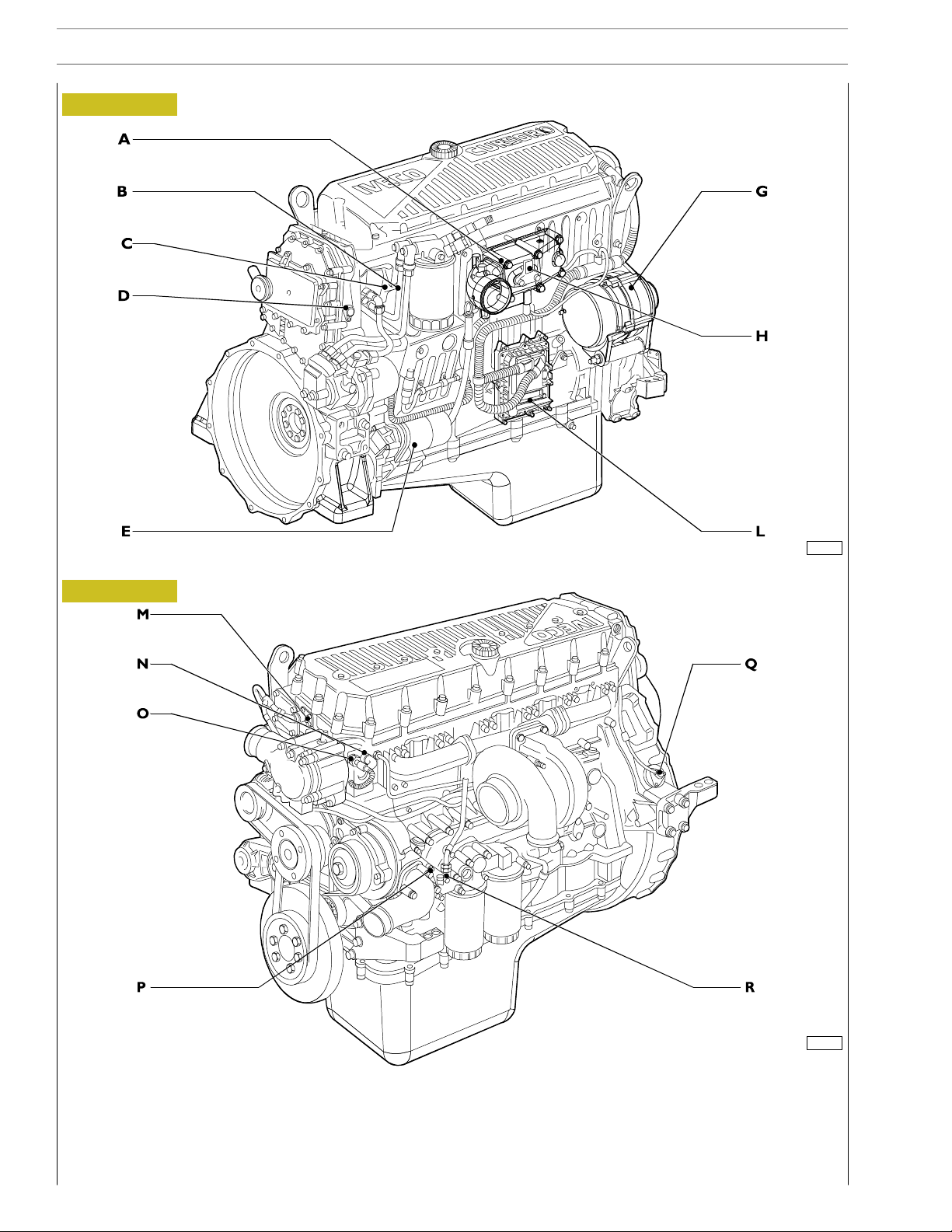
34
SECTION 3 - INDUSTRIAL APPLICATION
Components on the engine F3A (only for type F3AE9687A*E001)
Figure 7
CURSOR ENGINES F3A
ENGINE RIGHT-HAND SIDE VIEW
Figure 8
116711
116712
ENGINE LEFT-HAND SIDE VIEW
A. Resistance for engine warming - B. Fuel filter clogged signalling switch - C. Fuel temperature sensor - D. Engine rpm sensor
on camshaft - E. Starter motor - G. Alternator - H. Air temperature/pressure sensor - I. Conditioner compressor - L. EDC 7
control unit - M. Connector on engine block for connection with electro-injectors - N. Water temperature for EDC 7 -
O. Water temperature sensor - P. Oil pressure/temperature transmitter - Q. Engi ne speed on flywheel sensor -
R. Low oil pressure transmitter.
Base - May 2007 Print P2D32C003 E
Page 85

CURSOR ENGINES F3A
BLOCK DIAGRAM
Figure 9
SECTION 3 - INDUSTRIAL APPLICATION 35
116816
KEYS
1. Engine coolant temperature sensor - 2. Boost air pressure temperature sensor - 3. Fuel temperature sensor - 4. Boost air
pressure sensor - 5. Engine oil temperature and pressure sensor - 6. CAN H/L line - 7. Injectors - pump - 8. Pre-heating and
heating contactor - 9. Oil electric heater - 10. Main remote-control switch - 11. Flywheel sensor - 12. Distribution sensor -
13. Primary/secondary brake switch.
Base - May 2007Print P2D32C003 E
Page 86

36
SECTION 3 - INDUSTRIAL APPLICATION
EDC 7 UC31 electronic control unit
Figure 10
CURSOR ENGINES F3A
AC
B
102373
A. Electro-injector connector - B. Chassis connector - C. Sensor connector
Base - May 2007 Print P2D32C003 E
Page 87

CURSOR ENGINES F3A
EDC control unit PIN-OUT
Electric injector connector ”A”
Figure 11
SECTION 3 - INDUSTRIAL APPLICATION 37
Colour legend
B black
R red
U blue
W white
P purple
G green
N brown
Y yellow
O orange e
E grey
K pink
12
6
1
16
11
102374
5
ECU
Pin
Colour legend Function
1 Black Solenoid valve for electronic cylinder 5 injection
2 Black Solenoid valve for electronic cylinder 6 injection
3 Bleu Solenoid valve for electronic cylinder 4 injection
4 White Solenoid valve for electronic cylinder 1 injection
5 Green Solenoid valve for electronic cylinder 3 injection
6 Red Solenoid valve for electronic cylinder 2 injection
7 - Free
8 - Free
9 - Free
10 - Free
11 Yellow Solenoid valve for electronic cylinder 2 injection
12 Red Solenoid valve for electronic cylinder 3 injection
13 Red Solenoid valve for electronic cylinder 1 injection
14 Bleu Solenoid valve for electronic cylinder 4 injection
15 Green Solenoid valve for electronic cylinder 6 injection
16 Brown Solenoid valve for electronic cylinder 5 injection
Base - May 2007Print P2D32C003 E
Page 88

38
SECTION 3 - INDUSTRIAL APPLICATION
EDC control unit PIN-OUT
Sensor connector ”C”
CURSOR ENGINES F3A
Figure 12
6 8 16 9 15 22
4
Colour legend
B black
R red
U blue
W white
P purple
G green
N brown
Y yellow
O orange e
E grey
K pink
ECU
Pin
Cable colour Function
1 - Free
2 - Free
3 - Free
4÷8 - Free
9 W Valve gear camshaft sensor
10 R Valve gear camshaft sensor
11÷14 - Free
15 K Coolant temperature sensor
16 ÷17 - Free
Free
18 O/B Fuel temperature sensor
19 B Flywheel sensor
20 - Free
21÷22 - Free
23 W Flywheel sensor
24 N Engine oil temperature/pressure sensor ground
25 W Air temperature/pressure sensor power supply
26 Y Coolant temperature sensor
27 O/B Oil temperature signal from the engine oil temperature/pressure sensor
28 U Oil pressure signal from the engine oil temperature/pressure sensor
29 - Free
30 - Free
31 - Free
32 O Engine oil temperature/pressure sensor power supply
33 R Air temperature/pressure sensor power supply
34 G Air pressure signal from the air temperature/ pressure sensor
35 W/R Fuel temperature sensor
36 O Air temperature signal from the air temperature / pressure sensor
5
36 29302331
102375
Base - May 2007 Print P2D32C003 E
Page 89

CURSOR ENGINES F3A
EDC control unit PIN-OUT
Chassis connector ”B”
SECTION 3 - INDUSTRIAL APPLICATION 39
Figure 13
ECU
Pin
72
18
53
71
89
35
Cable Function
54
36
6
11
17
1 - Free
2 7151 +30 positive
3 7153 +30 positive
4 - Free
5 0151 Ground
6 0151 Ground
7 - Free
8 7151 +30 positive
9 7151 +30 positive
10 0151 Ground
11 0151 Ground
12 0094 Preheating actuation enable relay ground
13÷25 - Free
26 - Free
27 - Free
28 - Free
29 5163 EDC system diagnosis inducing switch power supply (presetting)
30 - Free
31 - Free
32 - Free
33 - Free
34 Green CAN - L line (ECB)
35 White CAN - H line (ECB)
36÷39 - -
40 - +15 positive
41 - Free
42 - H2O present in fuel oil sensor signal
43÷55 - Free
56 - Free
57 - Free
58÷67 - Free
68 - Free
69÷74 - -
75 9164 Preheating actuation enable relay positive
76÷88 - Free
89 2298 EDC control unit diagnosis K line
1
7
12
102376
Base - May 2007Print P2D32C003 E
Page 90

40
SECTION 3 - INDUSTRIAL APPLICATION
Pump injector
Figure 14
CURSOR ENGINES F3A
102405
N3.1 INJECTOR SECTION
The new N 3.I pump injectors are capable, thanks to the higher injection pressure, of atomizing the fuel in the combustion chamber
to a greater extent, thus improving combustion and therefore reducing the polluting exhaust emissions.
Figure 15
The function of the fuel pressure damper located on the
delivery pipe between the fuel filter and the cylinder head is
to attenuate the supply r eturn back pressure due to the
increase of the injection pressure.
102606
FUEL PRESSURE DAMPER
Base - May 2007 Print P2D32C003 E
Page 91

CURSOR ENGINES F3A
SECTION 3 - INDUSTRIAL APPLICATION 41
Engine coolant temperature sensor
This N.T.C. type sensor located on the water outlet sump on the engine head left measures coolant temperature for the various
operating logics with a hot or cold engine and identifies injection enrichment requirements for a cold engine or fuel reduction
requirements for a hot engine.
It is connected to electronic center pins 15/26.
Sensor behavior as a function of temperature:
-10°C8,10÷ 10,77 kOhm
+20°C2,28÷ 2,72 kOhm
+80°C0,29÷ 0,364 kOhm
At 60 to 90 _C, voltage at A5 and A22 ranges from 0.6 to 2.4V.
Figure 16
Description
Cable colour
To EDC center pin 15 (Sensor connector ”C”) K
To EDC center pin 26 (Sensor connector ”C”) Y
Base - May 2007Print P2D32C003 E
104266
Page 92

42
SECTION 3 - INDUSTRIAL APPLICATION
CURSOR ENGINES F3A
Fuel temperature sensor
Specifications
Supplier BOSCH
Max. tightening torque 35 Nm
Figure 17
104267
Description Cable colour
To pin 18 of EDC control unit (Sensor connector ”C”) O/B
To pin 35 of EDC control unit (Sensor connector ”C”) W/R
Base - May 2007 Print P2D32C003 E
Page 93

CURSOR ENGINES F3A
SECTION 3 - INDUSTRIAL APPLICATION 43
Flywheel pulse transmitter
Specifications
Supplier BOSCH
Max. tightening torque 8 ± 2Nm
Figure 18
Description Cable colour
To pin 19 of EDC control unit (Sensor connector ”C”) B
To pin 23 of EDC control unit (Sensor connector ”C”) W
Base - May 2007Print P2D32C003 E
104269
Page 94

44
SECTION 3 - INDUSTRIAL APPLICATION
CURSOR ENGINES F3A
Distribution pulse transmitter
Features
Vendor BOSCH
Torque 8 ± 2Nm
Resistance 880 ÷ 920 Ω
This induction type sensor located on the camshaft generates signals obtained from the magnetic flow lines that close through the
6 plus 1 phase teeth of a sound wheel mounted on the shaft.
The electronic center uses the signal generated by this sensor as an injection step signal.
Though electrically identical to engine rpm sensor mounted in the camshaft in is NOT interchangeable with it as it cable is shorter
and it features a larger diameter.
This sensor’s air gap is NOT ADJUSTABLE.
Figure 19
104269
Description
Cable colour
To EDC center pin 9 (Sensor connector ”C”) W
To EDC center pin 10 (Sensor connector ”C”) R
Base - May 2007 Print P2D32C003 E
Page 95

CURSOR ENGINES F3A
Ref.D
ipt
i
SECTION 3 - INDUSTRIAL APPLICATION 45
Figure 20
Figure 21
Air pressure/temperature sensor (85156).
This component incorporates a temperature sensor and a
pressure sensor.
IIt replaces the temperature sensors (85155) and pressure
sensors (85154) available in the preceding systems.
It is fitted onto the intake manifold and measures the
maximum supplied air flow rate used to accurately calculate
the amount of fuel to be injected at every cycle.
The sensor is powered with 5 V.
The output voltage is proportional to the pressure or
temperature measured by the sensor.
Pin (EDC) 25/C - 33/C Power supply
Pin (EDC) 36/C Temperature
Pin (EDC) 34/C Pressure
50324
Sensor external view
Oil temperature/pressure sensor (42030 / 47032)
This component is identical to the air pressure/temperature
sensor and replaced single sensors 47032 / 42030.
It is fitted onto the engine oil filter, in a horizontal position.
It measures the engine oil temperature and pressure.
The measured signal is sent to the EDC control unit which
controls, in turn, the indicator instrument on the dashboard
(low pressure warning lights / gauge).
Pin (EDC) 24/C - 32/C Power supply
Pin (EDC) 27/C Temperature
Pin (EDC) 28/C Pressure
The engine oil temperature is used only by the EDC control
unit.
50323
Linking connector
Figure 22
Control unit pin
escr
on
Oil Air
1 Ground 24C 25C
2 Temp. Sign. 27C 36C
3 +5 32C 33C
4 Press. Sign. 28C 34C
50344
Wiring diagram
Base - May 2007Print P2D32C003 E
Page 96
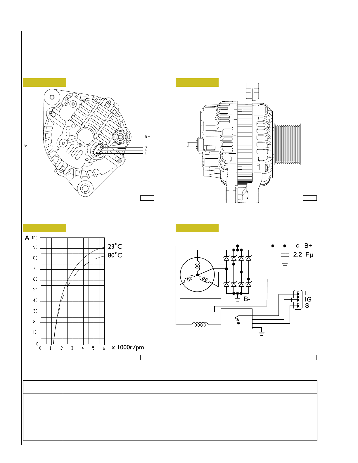
46
SECTION 3 - INDUSTRIAL APPLICATION
CURSOR ENGINES F3A
Alternator
Supplier MITSUBISHI
Technical features 24V - 90A
Figure 23
Figure 24
116714
Figure 25
116715
Figure 26
116713 116716
Pin Description
S +30
L Battery recharge light
B- Negative
B+ Positive
IG +15
Base - May 2007 Print P2D32C003 E
Page 97

CURSOR ENGINES F3A
SECTION 3 - INDUSTRIAL APPLICATION 47
Starting motor
Specifications
Supplier DENSO
Type 2280007550
Electrical system 24 Volt
Nominal output 5.5 Kw
Figure 27
104315
Base - May 2007Print P2D32C003 E
Page 98

48
SECTION 3 - INDUSTRIAL APPLICATION
CURSOR ENGINES F3A
Pre/post-heating resistance
The resistance is ~ 0,7 Ohm.
Such resistance is placed between the cylinder head and the suction manifold. It is used to heat up air during pre/post-heating
operations.
When the ignition key is inserted, should any one of the temperature sensors — water, air, gas oil — detect a value below 10°C,
the electronic control unit will activate pre/post-heating and turn on the relevant dashboard warning light for a variable time
depending on the temperature.
After that time, the warning light starts blinking thus informing the driver that the engine can be started.
When the engine is running the warning light goes off, while the resistance is being fed for a certain time as a result of post-heating.
If the engine is not started, with the warning light flashing, in 20 / 25 seconds, the operation is cancelled to prevent draining the
battery.
On the contrary, if reference temperatures are over 10°C, when the ignition key is inserted the warning light comes on for about
2 seconds and carries out the test and then goes out to signal that the engine can be started.
Figure 28
104270
Base - May 2007 Print P2D32C003 E
Page 99

CURSOR ENGINES F3A
EDC SYSTEM FUNCTIONS
The EDC 7 UC31 electronic center manages the following main functions:
Fuel injection
Accessory functions such as cruise control, speed limiter, PTO and the like
Self-diagnosis
Recovery
It also enables:
Interfacing with other electronic systems (if any) available on the vehicle
Diagnosis
Fuel dosing
Fuel dosing is calculated based on:
- accelerator position
-enginerpm
- quantity of air admitted.
The result can be corrected based on:
- water temperature
or to prevent:
-noise
-fumes
-overloads
-overheating
SECTION 3 - INDUSTRIAL APPLICATION 49
Pressure can be adjusted in case of:
- engine brake actuation
- external device actuation (e.g. speed reducer, cruise control)
- serious defects involving load reduction or engine stop.
After determining the mass of air introduced by measuring its volume and temperature, the center calculates the corresponding
mass of fuel to be injected into the cylinder involved, with account also taken of gas oil temperature.
Delivery correction based on water temperature
When cold, the engine encounters greater operating resistance, mechanical friction is high, oil is till very viscous and operating plays
are not optimized yet.
Fuel injected also tends to condense on c old metal surfaces.
Fuel dosing with a cold engine is therefore greater than when hot.
Delivery correction t o prevent noise, fumes or overloads
Behaviors that could lead to the defects under review are well known, so the designer has added specific instructions to the center
to prevent them.
De-rating
In the event of engine overheating, decreasing delivery proportionally to the temperature reached by the coolant changes injection.
Base - May 2007Print P2D32C003 E
Page 100

50
SECTION 3 - INDUSTRIAL APPLICATION
CURSOR ENGINES F3A
Injection lead electronic control
Injection l ead, or the start of fuel delivery expressed in degrees, can differ from one injection to the next, even from one cylinder
to another and is calculated similarly to delivery accordingto engine load, namely, accelerator position, engine rpm and air admitted.
Lead is corrected as required:
- during acceleration
- according to water temperature
and to obtain:
- reduced emissions, noise abatement and no overload
- better vehicle acceleration
High injection lead is set at start, based on water temperature.
Delivery start feedback is given by injection electro valve impedance variation.
Engine start
Cylinder 1 step and recognition signal synchronization (flywheel and drive shaft sensors) takes place at first engine turns. Accelerator
pedal signal is ignored at start. Star delivery is set exclusively based on water temperature, via a specific map. The center enables
the accelerator pedal, when it detects flywheel acceleration and rpm such as to consider the engine as started and no longer drawn
by the starter motor.
Cold start
Pre-post reheating is activated when even only one of the three water, air or gas oil temperature sensors records a temperature
of below 10 _C. The pre-heat warning light goes on when the ignition key is inserted and stays on for a variable period of time
according to temperature, while the intake duct input resistor heats the air, then starts blinking, at which point the engine can be
started.
The warning light switches off with the engine revving, while the resistor continues being fed for a variable period of time to
complete post-heating. The operation is cancelled to avoid uselessly discharging the batteries if the engine is not started within 20
÷ 25 seconds with the warning light blinking. The pre-heat curve is also variable based on battery voltage.
Hot start
On inserting the ignition key the warning light goes on for some 2 seconds for a short test and then switches off when all reference
temperatures are above 10 _C. The engine can be started at this point.
Run Up
When the ignition key is inserted, the center transfers data stored at previous engine stop to the main memory (Cf. After run),
and diagnoses the system.
After Run
At each engine stop with the ignition key, the center still remains fed by the main relay for a few seconds, to enable the
microprocessor to transfer some data from the main volatile memory to an non-volatile, cancelable and rewritable (Eeprom)
memory to make tem available for the next start (Cf. Run Up).
These data essentially consists of:
- miscellaneous settings, such as engine idling and the like
- settings of some components
- breakdown memory
The process lasts for some seconds, typically from 2 to 7 according to the amount of data to be stored, after which the ECU sends
a command to the main relay and makes it disconnect from the battery.
Base - May 2007 Print P2D32C003 E
 Loading...