

Page 1

Operating
M
a
6
3
m
G
C
e
n
e
r
Incl. EU Declar
anual
ation of Confor
ity
Vacu
VGC08
um
A, VG
aug
083B
Co
troll
tinb29e1 (201
-11)
1
Page 2

Prod
u
V
o
f
r
t
n
T
T
o
W
A
T
mcaIndAtiv
N
u
T
y
d
e
dpm
c
-
-
e
t
e
r
f
e
q
r
B
l
e
n
s
a
m
d
p
m
d
y
U
N
o
e
t
0
e
c
n
d
u
a
e
n
h
O
d
e
u
e
p
r
a
p
r
a
w
w
t
h
p
a
e
f
m
s
i
o
c
s
b
s
a
N
t
o
n
s
e
A
a
s
C
t
n
n
s
b
d
e
p
i
s
a
t
t
1
o
P
m
a
e
c
s
e
o
i
r
a
a
t
e
t
e
m
o
t
d
d
ct Identi
ication
I
all communi
n
meplate:
ations with I
FICON, plea
e specify th
information
n the produc
alid
Imp
ity
rtant Use
Informa
ion
his document
399
399
he part numb
If
not indicated
rrespond to
c
e reserve th
ll dimensions
here are ope
e
lectromechan
a
re a variety o
ent must tak
tion of this e
no event will
mages that
ny examples
e purposes.
p
rticular insta
tual use bas
a
o patent liabil
c
its, equipme
hroughout thi
s
mbols and s
applies to pr
700
701
er (PN) can b
otherwise in
he unit VGC
right to mak
are indicated
ational chara
ical equipme
uses for soli
every preca
uipment is s
INFICON be
esult from th
or diagrams i
Because of t
llation, INFIC
d on the exa
ity is assume
t, or softwar
manual we
fety messag
ducts with p
(VGC083A, use
(VGC083B, use
taken from
he legends, t
83A.They ap
technical ch
in mm.
teristic differ
t. Because o
state equip
tion and sati
fe and used
responsible
use or appli
cluded in thi
e many varia
N cannot as
mples and di
by INFICO
described in
se notes, no
s to make y
rt numbers:
ith BAG050 and
ith BAG051 or B
he product n
e illustration
ly to the VG
nges withou
nces betwee
these differe
ent, all perso
fy themselve
n an accepta
r liable for in
ation of this
manual are
les and requ
ume respon
grams.
with respect
this manual.
ices and appl
u aware of s
PGEG050)
AG052/053 and
meplate.
in this docu
083B by an
prior notice.
n solid state
ces, and be
ns that apply
that the inte
le manner.
irect or cons
quipment.
rovided solel
irements imp
ibility or liabil
to use of info
y internation
fety consider
EG050)
ent
logy.
quipment an
ause there
this equipnded appli-
quential
y for illustra-
sed on any
ty for any
mation cir-
lly recognize
tions.
entifies infor
I
p
hysical hazar
s
rious injury,
ation about
s which, if p
roperty dam
ractices or ci
ecautions are
ge, or econo
cumstances
not taken, co
ic loss.
hat can caus
uld result in d
electrical or
eath or
CA
TION
I
entifies infor
hysical hazar
oderate injur
ation about
s which, if p
, property da
ractices or ci
ecautions are
mage, or eco
cumstances
not taken, co
omic loss.
hat can caus
uld result in
electrical or
inor or
2
tinb29e
(2016-11) VGC083A_B.
m
Page 3

Liability and Warranty
NOTICE
Identifies information that is critical for successful application and understanding of
the product.
SHOCK HAZARD
Labels may be located on or inside the device to alert people that dangerous
voltages may be present.
INFICON assumes no liability and the warranty is rendered null and void if the enduser or third parties
• disregard the information in this document
• use the product in a non-conforming manner
• make any kind of interventions (modifications, alterations etc.) on the product
• use the product with accessories not listed in the corresponding product docu-
mentation.
tinb29e1 (2016-11) VGC083A_B.om 3
Page 4

Contents
Product Identification 2
Validity 2
Important User Information 2
Liability and Warranty 3
1 Introduction / General Information 6
1.1 VGC083A 6
1.2 VGC083B 7
2 Technical Data 8
3 Important Safety Information 11
3.1 Safety Precautions - General 11
3.2 Safety Precautions - Service and Operation 11
3.3 Electrical Conditions 12
3.3.1 Proper Equipment Grounding 13
3.3.2 Electrical Interface and Control 13
3.4 Overpressure and use with hazardous gases 13
3.5 Gases other than Nitrogen / air 13
4 Installation 15
4.1 Mechanical Installation - Controller 15
4.1.1 Panel Mount 15
4.1.2 Rack Mount 15
4.1.3 Mechanical Installation - Ionization Gauge 17
4.1.4 Mechanical Installation - Convection Gauge 17
4.2 Electrical Installation 18
4.2.1 Grounding 18
4.2.2 Installation 19
4.2.3 Connecting the Ionization Gauge Cable 19
4.2.3.1 Standard Nude and Glass IG Cable 20
4.2.3.2 Bakeable Nude IG Cable 21
4.2.3.3 Standard IG Cable Connector Pin Out 22
4.2.4 Connecting the PGE050 - connectors labeled "2" and "3" 23
4.2.5 Power Connection 24
4.2.6 Relay Connection 24
4.2.7 Analog Output Connection 24
4.2.8 Analog Input Connection (Capacitance Diaphragm Gauges, etc.) 24
4.2.9 Digital I/O Connection 25
4.2.10 RS232 / RS485 Serial Communications Connection 26
5 Operation - IG and CG 28
5.1 IG Emission Current 28
5.2 IG Degas 28
5.3 IG Filament Material Selection / Venting the Chamber 28
5.4 IG Over Pressure Shut Down 29
5.5 IG Over Temperature Shut Down 29
5.6 Convection Gauge (CG) Initial Setup 30
6 Setup and programming 31
6.1 Applying Power 31
6.2 Front Panel Display 31
6.3 User Interface Basics 32
6.4 Factory-Set Default Parameters 32
6.5 Programming 34
6.5.1 SETUP UNIT 34
6.5.2 ION GAUGE 35
6.5.3 ION GAUGE 40
6.5.4 RELAYS 40
6.5.5 Analog Output 42
6.5.6 SERIAL COMM 47
6.5.7 DISPLAY 47
4
tinb29e1 (2016-11) VGC083A_B.om
Page 5

7 Analog Output Charts & Equations (Nitrogen/Air Only) 49
7.1 Analog Output wide range measurement for IG - CG1 0.5 - 7V
(Nitrogen / Air only) 49
7.2 Analog Output for IG LOG N - 10 (Nitrogen / Air only) 50
7.3 Analog Output for IG LOG N - 11 (Nitrogen / Air only) 51
7.4 Analog Output for IG LOG N - 12 (Nitrogen / Air only) 52
7.5 Analog Output for IG 1.8 - 8.7 V (Nitrogen / Air only) 53
7.6 Analog Output for IG LINEAR (Nitrogen / Air only) 54
7.7 Analog Output for CG1 or CG2 1 - 8 V (Nitrogen / Air only) 54
7.8 Analog Output for CG1 or CG2 0 - 7 V (Nitrogen / Air only) 56
7.9 Analog Output for CG1 or CG2 NON - LIN (Nitrogen / Air only) 57
7.10 Analog Output for CG1 or CG2 LINEAR (Nitrogen / Air only) 59
8 Using the Gauge with Different Gases 60
8.1 Ion Gauge Display Correction Factors for Selected Gases 60
8.2 Effects of Different Gases on Convection Gauge Display 61
8.3 Effects of Different Gases on Analog Output 64
8.3.1 Ion Gauge Analog Output Correction Factors for Selected Gases 64
8.3.2 IG - CG1 0.5 - 7V Analog Output Correction Factors for Selected Gases 64
8.3.2.1 IG-CG1 0.5 - 7V Analog Output Correction Factors -
Ion Gauge Range 64
8.3.2.2 IG-CG1 0.5 - 7V Analog Output Correction Factors -
Convection Gauge Range 66
8.3.3 Convection gauge analog output for selected gases 66
8.3.3.1 CG1 1 - 8 V or CG2 1 - 8 V Analog Output Correction Factors -
Convection Gauge 67
8.3.3.2 CG1 0 - 7 V or CG2 0 - 7 V Analog Output Correction Factors -
Convection Gauge 68
8.3.3.3 CG1 NON-LIN or CG2 NON-LIN Analog Output Correction Factors -
Convection Gauge 69
9 Communication Protocol (Serial Interface) 70
9.1 Device Specific Serial Communication Info 70
9.2 INFICON RS232 / RS485 Command Protocol Summary 70
9.3 INFICON RS232 and RS485 Command Protocol Summary 71
9.4 RS232 GP 307 and 358 Protocol 74
9.5 RS485 GP 307 and 358 Protocol 75
10 Service 77
10.1 Calibration 77
10.2 Troubleshooting - IG Operation 77
10.3 Troubleshooting - IG Error Messages 78
10.4 Clearing Error Messages - IG 78
10.5 Research Screen 78
10.5.1 Research Screen (Diagnostic Display - IG) 78
10.6 Maintenance 80
11 Repair 81
12 Accessories 81
13 Storage 82
14 Disposal 82
EU Declaration of Conformity 83
For cross-references within this document, the symbol (→ XY) is used; for cross-
references to further documents listed under ‘Literature’, use is made of the symbol
(→ [Z]).
tinb29e1 (2016-11) VGC083A_B.om 5
Page 6

n
V
TcM
i
p
c
n
n
h
u
o
Tsy
T
h
B
o
T
m
P
x
n
G
s
8
O
n
A
e
n
w
n
o
n
n
m
a
e
e
o
G
n
r
G
h
o
8
d
e
u
n
a
t
t
g
o
-
d
t
a
l
u
n
m
c
e
0
p
d
e
d
s
®
m
e
GCo
A
G
&
f
m
u
u
a
o
d
1
s
a
u
a
a
o
o
a
c
d
o
i
d
d
o
f
1 I
1.1
troduct
GC083A
ypical Com
omplete Va
easureme
on / Ge
onents of t
uum Press
t System
eral Inf
e
re
rmatio
he Vacuum
stem which i
•
The VGC0
One INFIC
•
ionization g
One or two
•
Cables to i
•
1)
The VGC083
vacuum gaug
ypical compo
t
e figure belo
AG050 hot io
c
ntrol for up t
auge Control
s comprised
3A Vacuum
N BAG050
auge or othe
INFICON P
terconnect t
will also operate
head.
ents of the c
. The VGC0
n gauge hea
two enhanc
er VGC083A
f the followin
auge Contr
ude UHV EB
brands of nu
E050 convec
e VGC083A
the Granville-Phi
mplete vacu
3A provides
(IG). Additio
d convection
is a vacuum
:
ller
degas Bayar
e UHV EB-d
ion enhance
nd point-of-u
lips® Convectron
m measure
ower and op
ally, it provid
gauges (CG)
ressure mea
-Alpert hot c
egas B-A ga
pirani heads
se devices
convection enh
ent system
erating contr
s power and
.
urement
thode
ges
1)
nced pirani
re shown in
l for the
operating
he VGC083A
e
ither rack or i
h
igh rack-mou
i
portant infor
GE050 Oper
d
vice you int
e
ternal devic
, a controller
strument pa
t panels are
ation about
ting Manual.
nd to connec
s and cables
nit capable o
el mountable
vailable to
he PGE050
Read the Op
to the VGC0
that the VGC
V
B
P
1
controlling
Optional ind
ount the unit i
onvection ga
rating Manu
3A prior to c
83A is inten
C083A Vac
ntroller
G050 Ion G
E050 Conve
2 (CVG 1 &
ultiple gauge
stry standar
nto rack encl
ge please re
ls in their ent
onnecting an
ed to be use
om Gauge
uge
tion Gauges
2)
heads, is
19-inch, 2U
sures. For
er to the
rety for any
using the
with.
6
tinb29e
(2016-11) VGC083A_B.
m
Page 7

1.2 VGC
0
a
e
u
n
t
c
e
g
e
V
u
r
1
e
a
c
n
0
y
l
C
p
a
A
n
n
o
o
/
n
e
M
c
o
r
h
c
C
n
t
o
g
p
u
b
G
t
e
a
5
e
.
n
o
h
t
r
s
B
R
i
v
c
y
g
g
e
V
e
c
e
h
t
e
h
B
r
w
i
o
a
u
G
s
c
g
w
Typic
compl
Meas
83B
l Compone
te Vacuum
rement Sys
ts of the
Pressure
em
The Va
system
which is com
• The
• On
INFICON B
cath
ode ionizatio
gau
• On
• Cab
1)
or two INFIC
les to interco
The
vacu
Typical
components
the figu
BAG05
and op
uum Gauge
VGC083B V
es
GC083B will als
m gauge head.
e below. The
or BAG052
rating control
ontroller VG
rised of the f
cuum Gauge
G051 nude o
gauge or ot
ON PGE050
nect the VG
operate the Gra
f the comple
VGC083B pr
053 ion gau
for up to two
083B is a v
llowing:
Controller
BAG052 / 0
er equivalent
onvection en
083B and po
ville-Phillips® Co
e vacuum m
vides power
e heads (IG)
enhanced co
cuum pressu
3 glass I2R
brands of I
hanced piran
int-of-use de
nvectron® conve
asurement s
and operatin
Additionally,
vection gau
re measurem
ayard-Alpert
2
glass/nude
heads1)
ices
tion enhanced pi
stem are sho
control for e
it provides p
es (CG).
nt
ot
-A
ani
n in
ther the
wer
or
VGC083
Controll
BAG051
BAG052
PGE050
1 & 2 (C
B Vacoom G
r
Ion Gauge
or
/ 053 Ion Ga
Convection
G 1 & 2)
uge
ge
auges
The VG
either r
high ra
importa
PGE05
device
externa
C083B, a co
ck or instrum
k-mount pan
nt information
Operating
ou intend to
l devices and
troller unit ca
ent panel mo
ls are availa
about the P
anual. Read
onnect to th
cables that th
able of contr
ntable. Optio
le to mount t
E050 convec
he Operating
VGC083B p
e VGC083B i
olling multipl
nal industry s
e unit into ra
tion gauge pl
Manuals in t
ior to connec
intended to
gauge head
tandard 19-in
k enclosures
ase refer to t
eir entirety fo
ing and usin
be used with.
, is
h, 2U
. For
he
r any
the
tinb29e1 (2016-11) VGC0
83A_B.om
7
Page 8

2 Technical Data
Measurement range
Display
Functionality
IG sensor control
IG remote input signals
(digital I/O)
Setpoint relays
VGC083A
with BAG050
with PGE050
VGC083B
with BAG051 or BAG052/053
with PGE050
2×10
1×10
4×10
1×10
-11
-4
-10
-4
…1×10⁻³ Torr
…1000 Torr
…1×10⁻³ Torr
…1000 Torr
Units of measurement Torr, mbar, Pa (user selectable)
Pressure indication LED - 3 independent pressure display
channels, 3 digit plus 2 digit exponent per
channel
Set-up & programming screen OLED - displays state of all setpoint relays, IG
emission current, error messages for fault
conditions
VGC083A
(IG)
powers & operates one INFICON BAG050
nude UHV EB-Degas B-A hot cathode or other
equivalent brands
, (CG) powers & operates up to 2 INFICON PGE050
VGC083B
(IG)
convection or Granville-Phillips
Convectron
powers & operates one BAG051 or BAG052 /
053 or other equivalent brands of glass or nude
2
I
R B-A hot cathode
®
, (CG) powers & operates up to 2 INFICON PGE050
convection or Granville-Phillips
Convectron
®
®
(GP)
®
(GP)
IG sensor on/off, degas on/off and emission current can all be controlled via front
panel soft-keys, remote input signals (digital I/O) or serial communications. IG sensor can also be automatically turned on/off using measurements from one of the
user selectable convection or alternate gauges.
IG sensor on/off, degas on/off and emission current can also be set by applying
momentary continuity to ground. Also the 9-pin D-sub remote input DIGITAL I/O
connector provides pin-pin compatible signals with the GP 358 controller as well as
compatible signals with the GP 307.
Number 6
single-pole, double-throw (SPDT), user assignable to any of the gauges
Contact rating 5 A at 30 V (dc), 5 A at 250 V (ac), resistive
load
8
tinb29e1 (2016-11) VGC083A_B.om
Page 9

Analog output
Analog input
Serial communications
Status output
IG (Ionization Gauge)
Ambience
Housing
IG analog output
Log-linear
0 … 10 V (dc), 1 V/decade, or
1.7 … 9.3 V (dc) (nominal 1.8 … 8.7 V (dc)),
0.8 V/decade
Linear 0 … 10 V (dc) (useable over 3 decades)
Combination IG + CG analog
Log-linear
CG analog output
Log-linear
0.5 … 7 V (dc), 0.5 V/decade
1 … 8 V (dc), 1 V/decade, or
0 … 7 V (dc), 1 V/decade
Linear 0 … 10 V (dc) (useable over 3 decades)
Non-linear analog S-curve 0.375 … 5.659 V (dc)
CDG one 0 … 10 V (dc) analog input signal from a
CDG when used as an alternate gauge to CG2,
or analog input from one of the following
INFICON modules: PGE300, PGE500,
BAG300
Protocol RS485 / RS232 - ASCII protocol
IG sensor on/off status message is displayed on the front panel, by serial communications and by SPDT relay (DIGITAL I/O Connector) rated at 1 A at 30 V (dc)
resistive, or 1 A at 30 V (ac) non-inductive.
IG degas on/off status or IG error conditions are displayed on the front panel, by
serial communications and by an open collector transistor output (ground emitter)
rated at 40 V max. VCE, 50 mA IC max.
IG filament switching User selectable between filament 1 or 2 using
the front panel soft-keys or RS232 / RS485
serial comm
IG emission current 100 μA, 4 mA, 10 mA or automatic switching of
emission current (auto ranging)
IG degas 40 W, resistive
-3
IG overpressure protection
(turns ion gauge off at the
following factory default settings)
1 × 10
5 × 10
1 × 10
Torr at 100 μA emission current
-4
Torr at 4 mA emission current
-4
Torr at 10 mA emission current
Temperature
Operation
Storage
0 … +40 °C
–40 … +50 °C
Relative humidity 0 … 95, non-condensing
Altitude
Operating
Storage
max. 2500 m (8200 ft.)
max. 12500 m (41000 ft.)
Pollution degree II
Degree of protection IP20
Housing aluminum extrusion - black powder paint finish
tinb29e1 (2016-11) VGC083A_B.om 9
Page 10
M
iVG
WVG
c
G
G
V
C
m
m
2
5
y
2
D
D
D
a
e
0
b
b
1
r
d
o
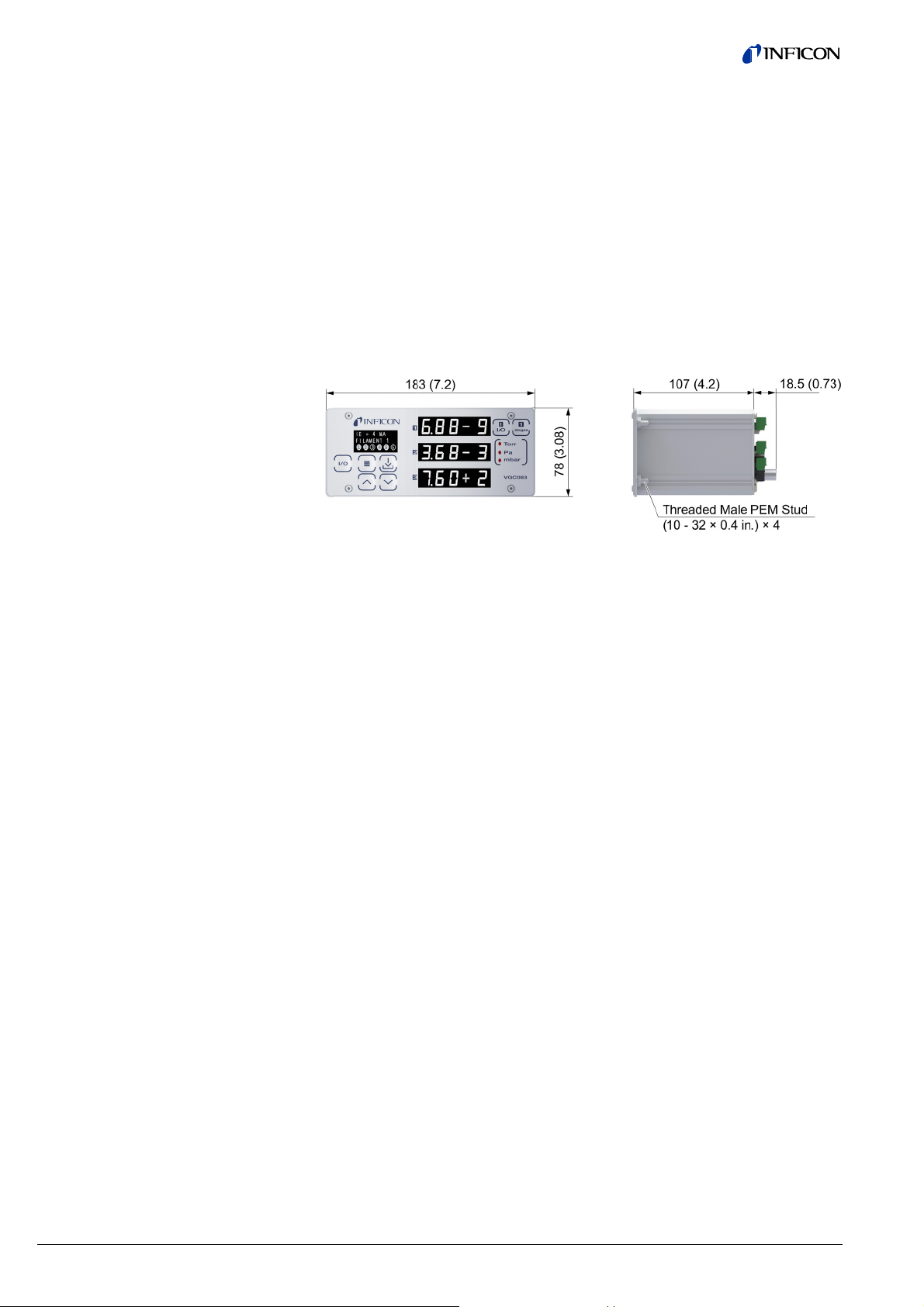
ains specifi
D
mensions
C083A, V
ations
C083B
oltage
onnectors
IG & CG
Digital I/O
Serial com
RS23
RS48
analog I/O,
power
m (inch)
unications
setpoint rela
s,
20 …
power
gauge
9-pin
9-pin
9-pin
plugg
includ
8 V (dc), 20
reversal and
cable assem
-sub male
-sub female
-sub male
ble terminal
d)
W protected
transient ove
blies provide
lock (mating
against
-voltages
by INFICON
connectors
eight
C083A, V
C083B
.7 kg (1.7 lb.)
0
10
tinb29e
(2016-11) VGC083A_B.
m
Page 11

t
e
t
i
f
t
t
p
r
d
n
F
h
t
e
o
v
o
o
d
A
d
m
A
d
e
e
t
t
b
e
e
a
s
e
d
r
m
i
h
m
m
c
n
o
C
a
A
e
o
n
n
a
A
o
c
n
N
d
w
d
q
r
e
e
e
u
.
o
N
d
o
,
s
n
t
e
m
c
m
q
w
n
e
c
t
e
o
m
o
e
t
s
a
c
w
s
w
y
p
f
h
o
r
a
o
y
h
s
d
h
c
r
i
s
p
y
e
y
f
r
t
d
D
C
c
m
u
r
r
e
d
u
a
u
d
b
s
m
o
n
a
o
h
e
r
m
y
a
n
n
c
o
o
s
N
d
d
e
l
u
o
a
h
c
T
n
u
D
o
a
s
o
n
p
e
i
m
n
h
n
e
3 Impo
3.1 Safe
Gen
rtant Sa
y Precau
ral
ety Info
ions -
mation
INFICO
provide
this ma
To avoi
ment.
bodily
Failure
and int
tomer's
Althoug
INFICO
operati
installat
This de
Hazard
product
tection
provide
N has design
it is installe
ual. Please
WARNI
d serious inj
ailure to co
arm, includ
o comply wit
nded use of t
failure to co
h every atte
N cannot anti
n, or mainte
ion and use
ice meets F
us voltages
should never
f the operato
.
d and tested
and operate
ead and foll
G
ury or death
ply with the
ng death, an
these warni
his instrumen
ply with thes
pt has been
ipate every
ance of the
f this product,
C part 15 re
re present wi
be operated
r from accide
this product t
within the st
w all warnin
follow the s
e safety pr
or propert
gs violates t
. INFICON di
instructions.
ade to consi
ontingency th
odule. If you
please conta
uirements for
th this produ
ith the cove
tal contact w
o provide saf
rict safety gui
gs and instr
fety inform
cedures co
damage.
e safety stan
sclaims all lia
er most pos
at arises fro
have any que
ct INFICON.
an unintenti
t during norm
s removed u
ith hazardous
and reliable
elines provi
ctions.
tion in this
ld result in s
ards of insta
ility for the c
ible installati
various inst
tions about t
nal radiator,
al operation.
less equivale
internal volta
service,
ed in
ocu-
rious
lation
s-
ns,
llations,
e safe
lass A.
he
nt proges is
3.2 Safe
Serv
y Precau
ce and O
ions -
eration
W
the pro
Do not
INFICO
service
use this
W
perform
After se
service
specifie
shock o
product
To redu
moistur
not spill
have b
duct if i
Due to
is possi
that the
equipm
has be
Ensure
ground.
Ensure
electric
Use a p
power
RNING! Th
uct enclosur
odify this pr
N service trai
and repair ce
product if un
RNING! S
ing any servi
rvicing this pr
person. Whe
d by INFICO
r other hazar
will void the
ce the risk of
. These pro
any type of li
en damaged.
is damaged.
he possibility
ble that the p
product be p
nt grounding
n compromis
the enclosur
that the vacu
lly grounded
ower source
upplies.
ere are no op
. Refer servi
duct or subs
ed personne
ter to ensur
uthorized m
urce power
ing.
duct, ensur
replacemen
Substitution
s. Use of un
arranty.
fire or electri
ucts are not
uid onto the
Immediately
of corrosion
oduct’s safet
riodically ins
. Do not use i
d.
of the unit is
m port on w
f 20 … 28 V
rator service
ing to service
itute any part
l. Return the
that all safet
difications ha
ust be remov
that all safet
parts are req
of non-quali
uthorized pa
shock, do no
aterproof an
e products.
ontact INFI
hen used in
could be co
ected for so
the equipme
connected di
ich the vacuu
dc), 200 W o
able parts or
trained pers
without aut
roduct to an
features are
ve been mad
ed from the p
checks are
uired, ensure
ied parts ma
ts or modific
t expose this
careful atte
o not use the
ON to arrang
ertain enviro
promised ov
nd electrical
nt grounding
ectly to a go
m gauge sen
r use INFIOC
djustments i
nnel.
orization of q
NFICON qua
maintained.
.
oduct prior t
ade by a qu
that the part
result in fire,
tions made t
product to rai
tion must be
se products if
return of th
mental cond
r time. It is i
onnections a
r electrical i
d quality eart
ors are mou
series optio
side
alified
lified
o not
lified
are
electric
this
or
aid to
they
pro-
tions, it
portant
nd
sulation
ted is
nal
tinb29e1 (2016-11) VGC0
83A_B.om
11
Page 12

3.3 Electrical NConditio
n
T
Tinvi
D
CtoIf
o
DwEDD
N
wofle
f
xtamTso
h
S
Afie
o
otath
c
y
n
q
a
h
O
r
e
g
m
a
G
s
m
e
g
o
c
m
e
a
B
a
r
G
l
e
i
d
a
t
a
s
c
c
u
n
e
a
d
w
s
G
n
o
o
m
y
i
a
t
d
e
y
r
x
n
h
f
n
g
m
h
a
o
e
r
a
o
r
r
r
p
n
0
s
g
n
u
o
h
e
s
a
a
a
c
t
e
n
T
e
u
l
h
o
a
e
n
m
s
m
e
e
c
0
i
m
m
s
t
m
s
a
u
e
a
s
o
n
r
c
t
c
1
t
N
n
e
e
a
n
t
n
t
o
l
m
p
i
b
o
t
a
e
e
a
m
s
t
d
a
n
v
o
d
s
e
e
n
a
-
o
e
y
-
t
OTICE
s
urn off power
urn off power
g normally a
ce personnel
b
this operati
is important t
It
ctions and e
n
lectrical insul
e
o not use if t
ontact INFIC
INFICON fo
measured pr
nditions, the
c
The pressu
•
The pressu
•
The pressu
•
uring the De
ill turn off but
nsure vacuu
egas of the B
o not attempt
h
re.
ever use an
hen the Ion
other gauge
ading to fila
b
fore pressur
you are usin
I
perating the i
o
e
tended perio
in emission
inated by res
he most com
r or head el
a
ll possible ind
aracterized
c
e
lectrodes, or
ensors that f
fter servicing
d service pe
WARNIN
e
ning electrica
a
re maintained
c
ntact with th
a
gaseous env
rounded con
g
c
ming in cont
ge potential.
e gas inside
to the unit be
to the unit if
cording to thi
for any servi
g manual.
hat the produ
quipment gro
tion has bee
e unit has be
N for return
evaluation.
ssure excee
ion gauge wil
re exceeds 1.
re exceeds 5.
re exceeds 1.
as cycle, if th
the filament
level is less
AG05x serie
to turn the I
uxiliary or co
auge filamen
may not all
ent damage.
is allowed t
dual filamen
n gauge fila
d of time ma
urrent in appl
idual applicat
on cause of
ctrodes. Nois
ications of ga
s either: A) a
) an accumu
il due to cont
these produc
son
! When high
shock hazar
at earth grou
gas contain
ironment ma
uctor of elect
ct with an e
This conditio
he vacuum c
ore attempti
cable or plu
instruction
e or troubles
t be periodic
nding. Do n
compromis
n dropped o
uthorization
s the thresh
l turn off:
00 × 10
-3
Tor
00 × 10-4 Tor
00 × 10-4 Tor
e measured
ill remain tur
than 5.00 x 1
ionization ga
on if the pre
vection gau
t in use is co
w for timely t
Always turn
rise above 1
t IGs, it is hig
ents 1 and 2
result in failu
cations wher
on or proces
all vacuum g
y or erratic re
ge contamin
chemical rea
lation of mate
mination are
s, ensure tha
voltage is pr
may exist u
nd potential.
d in vacuum
couple dang
icity. A perso
posed, ungro
applies to al
amber (vacu
g to service t
is damaged
anual. Cont
ooting condit
lly inspected
t use if the eq
d.
the enclosur
nd instructio
lds that are d
at 100 μA e
at 4 mA emi
at 10 mA e
ressure exce
ed on.
-5
Torr befor
uge heads.
sure is near t
e to automati
structed of tu
rn off of the t
ff the IG filam
.00E-03 (1.0
ly recommen
An inactive f
re of that fila
the filament
related che
uge failures i
dings and to
tion. Conta
tion of proce
rial on the he
not covered
all safety ch
sent in any v
less all expo
his applies t
chambers. A
rous high vol
could be se
nded electri
products tha
um/pressure
e controller.
or the produc
ct qualified I
ion that may
for sound el
uipment grou
has been d
ns for returni
efined under
ission curre
sion current.
ission curren
ds 1.00 × 10
attempting t
he threshold
ally turn off t
ngsten. The
ungsten fila
ent (tungsten
× 10-3) Torr.
ded to period
ilament not o
ent to establ
coating may
istries.
s contaminati
al gauge he
ination can g
ss gases with
d (sensor) el
nder warrant
cks are mad
cuum syste
ed electrical
all products
electrical di
tage directly
riously injure
al conductor
may come i
ontainment
is not operat
FICON serot be covere
ctrical con-
nding or
maged.
g the product
he following
t.
.
-4
Torr, Dega
initiate
imits defined
e Ion Gauge
esponse tim
ent possibly
manually
ically alternat
erating for a
sh and main-
ecome cont
n of the sen
d failures are
nerally be
head / sens
ctrodes.
.
by a quali-
, a life threat
conductors
hat come in
charge within
o any un-
or killed by
t high vol-
contact with
essel).
-
-
r
12
tinb29e
(2016-11) VGC083A_B.
m
Page 13

3.3.1 Pro
p
u
c
p
h
e
m
r
a
s
h
A
h
e
n
d
n
g
e
A
s
i
y
d
n
s
o
A
r
s
e
m
e
c
e
n
o
g
e
A
e
d
e
a
v
r
A
a
y
o
s
A
m
o
e
o
A
z
u
a
q
o
f
m
U
e
A
o
n
a
a
a
A
s
s
q
y
o
s
p
p
h
t
h
o
f
a
e
e
s
b
u
A
o
d
e
o
A
v
u
a
o
g
s
e
t
u
n
c
n
e
c
e
u
r
e
f
y
y
r
a
r
o
e
i
t
r
m
f
c
h
)
e
c
r
w
o
m
a
v
o
o
e
a
e
m
G
o
s
i
m
o
l
t
s
f
k
a
e
s
d
e
p
i
s
x
h
t
o
t
p
w
r
p
i
o
g
n
e
r
a
t
r
s
i
e
e
o
o
b
o
d
l
l
s
f
i
h
s
u
d
e
c
g
w
e
(
e
x
s
u
c
e
i
r
e
o
e
t
y
e
h
e
o
e
u
y
s
v
h
w
e
r
p
v
y
a
l
c
n
e
i
r
p
o
e
n
2
e
e
p
d
r
Gro
3.3.2 Ele
Con
3.4 Over
with
er Equip
nding
trical Inte
trol
pressure
hazardou
ent
face and
nd use
gases
W
present
which t
ground
groundi
intende
any co
earthin
pressur
W
harm,
trical d
It is the
and an
are use
any sig
your sy
taken t
W
pressu
system
In case
implem
an auto
pressur
The va
pressur
sure ins
an isola
sure co
lower; f
the gau
correct
RNING! Ha
in many vac
e ion gauge
d. Consult a
ng. Proper gr
operation o
trol module
conductor.
measurem
RNING! In
hield all con
scharges in
user’s respo
connections
in a safe m
als to autom
tem design
prevent injur
RNING! In
e inside you
component
where an e
nt fail-safe s
matic backfill
s if the pres
uum gauge h
s above 20
ide the senso
tion valve or
ditions. Wit
r example, a
e tube from
d barometric
ardous volta
um processe
nd the conv
ualified Elec
unding of yo
the equipme
ust be conne
se a ground l
nt devices if
rder to prot
ductors whi
or around th
sibility to ens
made to exte
nner. Always
te your proc
nd ensure sa
and propert
tall suitable
vacuum ch
are capable
uipment failu
stem operati
peration wh
ure relief dev
ads used wi
sia (1000 tor
r. If your cha
ressure relie
some fittings
quick-conne
he vacuum c
(atmospheric
es that could
. Verify that t
ction gauges
rician if you a
r equipment
t. The vacuu
ted directly t
ug on the vac
ecessary.
ct personne
h are subjec
vacuum sy
re that the el
nal devices,
double chec
ss. Perform
eguards and
damage.
rotective d
mber to les
of withstan
e could caus
n. For exam
re a malfunct
ce was not in
h this product
); DO NOT e
ber goes to
device to pro
, actual safe
, O-ring com
amber fitting
pressure.
seriously inju
he vacuum c
are mounted
re in doubt a
is essential f
m gauge hea
a good qual
uum connecti
l from electri
t to potentia
stem.
ectrical signa
or example, r
the system
hazardous o
personnel sa
vices that w
than what t
ing.
a hazardous
le, use a pre
ion could res
talled on the
are not inten
ceed 35 psig
igher pressu
tect the gaug
verpressure
ression fittin
with only a fe
re or cause d
nnection por
are electricall
out your equi
r safety as w
s and enclos
ity equipment
on flange of t
c shock and
high voltag
s from this pr
lays and sol
et-up before
peration anal
ety measure
ll limit the le
e vacuum c
condition, al
sure relief d
lt in high inte
chamber.
ed for use at
(< 2 ½ bars)
res, you shou
tube from o
onditions ma
may forcibly
psi over loc
ath are
s on
pment
ll as
ure of
e
bodily
elec-
duct
noids,
sing
sis of
are
el of
amber
ays
vice in
nal
res-
ld install
erpres-
be
release
l un-
3.5 Gas
Nitro
s other t
gen / air
an
C
to incr
sure si
may ca
into th
flamm
of the
ment, c
expose
pressu
W
without
INFICO
Do not
unless
analog
when u
W
of flam
of expl
incand
an expl
UTION! If t
ase above l
e), vacuum
use leaks th
atmospher
ble gases ar
acuum/pres
ould cause
the gauge t
e when usin
RNING! Do
referring to c
N gauges an
ttempt to us
ou have appl
utput to dete
ing convecti
RNING! Do
able gases,
sive or comb
scent temper
sion which c
e internal pr
cal uncorre
ittings may
t would allo
of the surro
examples
ure contain
odily injury
be internal
g hazardous
not attempt t
rrection fact
modules ar
with other g
ied correction
rmine the tru
n gauges to
not use the I
apors or fum
stible gases
tures and co
uld result in
ssure of a v
ted baromet
elease and
the gas ins
nding envir
f hazardous
ent vessel i
nd possible
olume to pre
gases.
use with gas
r data tables.
calibrated fo
ses such as
factors to bo
measured p
easure pres
in an explos
s. Do not us
r gas mixtur
uld become a
erious injury
acuum gaug
ic pressure
ossible over
ide the gaug
nment. To
gases that if
to the atmo
damage to e
ssure above
es other than
direct reado
rgon (Ar) or
h the display
essure. This
ure of gases
ive atmosphe
the IG to m
s. The sens
n ignition sou
or death.
device is a
atmospheri
ressure co
tube to rel
ic, pyrophor
allowed to le
pheric envi
uipment. N
local atmos
nitrogen (N2)
t of nitrogen
arbon dioxid
d pressure a
s particularly
other than N
e or in the pr
asure the pr
r filaments o
rce. This coul
lowed
pres-
ditions
ase
c and
ak out
on-
eve
heric
or air
r air.
(CO2)
d the
critical
/Air.
sence
ssure
erate at
cause
tinb29e1 (2016-11) VGC0
83A_B.om
13
Page 14

eththte
G
m
f
m
o
e
v
s
h
e
g
u
m
v
e
m
o
e
c
1
e
u
s
o
n
y
WARNIN
s
nce of flam
e pressure o
e gauge nor
mperature c
a
nd gas mixtur
o
r death.
! Do not us
able gases,
explosive or
ally operate
uld exceed t
e. This could
the PGE050
apors or fum
combustible
at 125 °C, b
e ignition te
cause an exp
in an explosi
s. Do not us
ases or gas
t if malfuncti
perature of c
osion which
e atmospher
the PGE050
ixtures. The
n should occ
rtain combu
ould result in
or in the pre
to measure
sensor wire i
r, the wire
tible gases
serious injur
-
14
tinb29e
(2016-11) VGC083A_B.
m
Page 15

4 Installation
4.1 Mechanical Installation Controller
4.1.1 Panel Mount
Procedure
The unit is intended for indoor use only. The unit is offered as a space saving half
rack design. It may also be used as a bench top device or easily installed in an
instrument panel. Optional EIA-standard rack mount panels are available for either
full rack or dual, side-by-side rack mount installation. When mounting multiple units
in your rack mount enclosure or mounting the unit below other electronic equipment in your rack, allow at least 1U of space (1.75 in., 45 mm) between the units to
ensure adequate ventilation.
Make a cutout in your rack panel or instrument control panel as shown in
the drawing below. Be sure to allow clearance behind the panel for the instrument as well as connectors and cables at the back of the instrument.
Optional EIA-standard, 19-inch, 2U height rack mount panels are available
from INFICON. The optional rack mount panels are provided with panel cutouts and mounting holes to allow efficient mounting of your VGC083 unit.
Drill four guide holes on each side of the panel cut out (two on each side)
with dimensions as shown in the panel cut-out drawing above.
Slide the unit into the panel hole cut-out. Guide the four studs on the back of
the unit front panel face plate thru the four holes next to the panel cut-out.
Use four # 10-32 Hex Nut (provided with instrument) to tighten the unit to
the panel.
4.1.2 Rack Mount
tinb29e1 (2016-11) VGC083A_B.om 15
Optional EIA-standard 19-inch wide, 2U height rack mount panels available from
INFICON (→ 81):
Page 16

Single cut-out panel
All dimensions in inches.
Single cut-out panel
All dimensions in inches.
The single cut-out and dual cut-out rack mountable panels shown above are available from INFICON. Panel color matches the front panel of VGC083 units. Screws
for mounting to rack enclosure are included.
16
tinb29e1 (2016-11) VGC083A_B.om
Page 17

4.1.3 Mec
z
CVGC
s
u
s
a
h
n
o
e
i
h
s
m
h
s
c
m
g
/
m
t
r
e
h
c
s
s
n
n
h
m
TEb
g
d
h
s
h
n
i
e
m
g
t
p
h
o
s
o
m
.
o
a
s
a
d
0
t
i
c
i
A
y
2
s
e
h
o
g
h
h
o
f
m
r
u
0
s
T
a
n
d
T
t
o
U
l
s
e
b
e
e
b
r
g
s
a
h
m
0
r
p
i
0
s
s
t
N
i
a
C
A
d
o
b
s
a
e
o
b
t
e
m
g
w
e
o
e
b
e
d
s
e
1
A
o
c
p
l
i
n
f
e
r
e
u
u
y
Ioni
VG
hanical In
ation Ga
083A
tallation -
ge
4.1.4 Mec
Con
083B
hanical In
vection G
tallation -
uge
NOTIC
BA
Mount t
ure. Lo
ween y
pressur
may als
The ion
mount t
conden
Do not
Vibratio
chanica
Shield t
or in a
For ele
vacuu
proper
lic-type
Fittings
installat
Use all
pected
For mo
the Op
Mount t
or restri
proces
change
Mounti
and co
cooling,
Mount t
reading
1 Torr,
or
G051
he ionization
g or restricte
ur process c
changes. M
o cause mea
ization gauge
he gauge wit
ation collecti
ount the ion
ns may caus
l stress to co
he ionization
puttering sys
trical safety
chamber. W
rounding. D
flange clamp
Flanges - foll
ion and use.
metal vacuu
o be below 1
e detailed inf
rating Manu
he PGE050a
cted, small di
chamber an
.
g the PGE05
trol instability
such as hea
he PGE050w
errors may o
ounting pos
he VGC083
B-degas Ba
rands of equ
BAG05
auge as clo
, small diam
amber and t
unting the io
urement and
can be moun
port down to
g in the gau
zation gauge
unstable rea
ponents in t
auge near io
em.
urposes the
en using KF
not attempt t
.
w the fitting/
fittings with
00 × 10-7 Tor
rmation abo
l for the PGE
close as po
meter tubing
the gauge.
too close to
. Do not mou
ers or air con
th its main ax
cur above 1
tion has little
can operate
ard-Alpert h
ivalent nude
, BAG053
e as possible
ter tubing wil
e gauge. Thi
nization gaug
control insta
ed in any ori
help minimiz
e.
where it will
ings, measu
e ionization
n or electron
ousing of the
langes, meta
modify your
lange manuf
etal seals w
(1.33 × 10⁻⁷
t the PGE05
50.
sible to the p
will create a
his may caus
gas source
t the PGE05
itioning vent
is horizontal (
orr if the uni
o no effect.
one INFICO
t cathode ion
HV EB-deg
The VG
one INFI
or one B
enclose
hot cath
or other
gauges.
to the pressu
l create a pre
may cause
e too close to
ility.
ntation, how
the effect of
e subjected t
rement errors
auge.
ources such
gauge must
l clamps mus
flange in ord
cturer's reco
en operating
mbar, 1.33 ×
convection
essure you
ressure diffe
e a delay in r
inlet may als
near a sourc
.
see diagram
is not mount
BAG050 nu
zation gauge
s B-A gauge
083B can op
ON BAG05
G052/053 gl
I2R Bayard-
de ionization
rands of equ
re you want t
sure differen
delay in res
a gas source
ver, if possib
any particles
excessive v
and possible
as an electro
e grounded t
be used to e
r to use non-
mendations
pressures ar
10-5 Pa).
auge, please
ant to measu
rence betwee
sponse to pr
cause meas
of heating o
elow). Press
d horizontall
e UHV
or other
.
rate
nude
ass
lpert
gauge
ivalent
mease betonse to
inlet
e,
or
bration.
me-
beam
o the
nsure
metal-
or
ex-
refer to
e. Long
n your
ssure
rement
r
re
. Below
tinb29e1 (2016-11) VGC0
83A_B.om
17
Page 18

E
o
MpDtiost
o
w
h
t
o
m
oth
h
E
n
s
o
g
W
h
h
o
a
d
U
d
d
o
r
t
o
w
a
t
h
p
D
a
h
d
v
s
n
e
u
r
e
o
T
w
k
n
w
c
G
e
m
m
s
d
T
g
t
e
h
o
o
h
1
e
b
e
o
g
d
m
m
s
p
a
t
b
s
k
n
o
-
o
y
a
4.2
4.2.1
lectrical
Groundin
Installati
g
n
ount the PG
rticles or co
o not mount t
ns may cau
ress to comp
F
langes/ Fittin
f
llowing:
-
NPT fittings:
a
nt compound
raps of pipe t
g
uge into the
e gauge.
t
Be sure t
g
rounded to pr
fi
tings, especi
p
roduce a goo
c
nnected to.
easurement
t
earth groun
at you conne
e
rth ground c
e green colo
t
050 with por
densation fr
he PGE050
e unstable re
onents in the
s - follow the
hen connec
or wrap the t
hread seal ta
gauge port.
e vacuum g
otect personn
lly those wit
electrical co
se a ground
evice if nece
via a good q
ct a separate
nnection an
ed screw pro
down, if pos
m collecting i
here it will b
dings, meas
PGE050.
manufacture
ing the devic
readed porti
e such as P
o not use a
uges and the
el from shoc
O-rings whe
nnection bet
lug on the va
ssary. The V
uality equipm
12-AWG eart
the location
ided) on the
ible, to help
the gauge.
subjected to
rement error
's recommen
using a NP
n of the tubin
FE (Teflon®)
rench or othe
rest of your v
and injury. B
not used wit
een the gaug
uum connect
C083 control
nt earthing c
ing conduct
arked with t
ack panel of
inimize the
excessive vi
s and possibl
ations and n
fitting, apply
with one-an
tape and han
r tool which
acuum syste
aware that
h metal clam
e and the ch
ion flange of
unit should
onductor. It i
r between a
e earth grou
the VGC083.
ffect of any
ration. Vibra-
mechanical
te the
a thread seal
d-a-half to tw
tighten the
ay damage
are properl
ome vacuum
s, may not
mber it is
he pressure
e connected
encouraged
nown facility
d symbol (vi
18
tinb29e
(2016-11) VGC083A_B.
m
Page 19

4.2.2 Inst
a
e
n
b
e
i
o
e
m
V
i
e
C
O
b
e
e
t
t
g
n
e
e
s
o
a
h
3
t
t
e
O
e
g
h
c
n
e
a
r
e
t
u
w
c
.
e
A
a
o
B
n
c
h
c
c
V
a
a
m
f
b
t
b
o
8
G
c
o
o
o
n
o
c
e
f
e
llation
A good,
necting
on the
recommend
or disconnec
ack panel of
d practice is
ing it. The el
he device as
o remove po
ctrical conne
shown below
er from any
tions for the
.
able prior to
GC083 are l
oncated
4.2.3 Con
Gau
necting th
ge Cable
Ionizatio
Good, r
ing or d
brands
propriat
low) fro
of the
easy or
low-lev
cable w
the BN
CAUTI
trolled
disconn
options
equipm
commended
isconnecting i
f equivalent
e length of io
the ion gau
GC083 label
entation of th
l ion current
ith the BNC c
connector l
N! When c
y the VGC08
ect power to
to devices or
nt damage o
practice is to
t. With INFIC
auges) conn
gauge cabl
e head on t
d "1". The cir
mating con
ignal from th
nnector at th
beled "COL".
anging or m
, you must fi
he VGC083b
removing/ins
r possible inj
remove pow
Ns nude B-
cted to your
(see various
e vacuum ch
ular plastic c
ectors. The
ion collector
e controller e
king cabling
st turn power
fore either c
alling option
ry to personn
r from any c
ionization g
vacuum cha
IG cable con
mber to the
onnector (CP
NC connecto
electrode of
d of your ca
onnections t
to the VGC0
anging cable
ards in the V
el.
ble prior to c
uge head (or
ber, connect
igurations sh
ack panel co
) is keyed t
r is for conne
he head. The
le is connect
any device c
3 OFF. Failu
connections
C083 may r
nnectother
an ap-
wn be-
nector
allow
ting the
coaxial
d at
onre to
rom
sult in
tinb29e1 (2016-11) VGC0
83A_B.om
19
Page 20

1
B
VGC083A:
B
d
A
e
0
a
e
G
P
P
G
mvayo
y
→BAG
b
→
m
n
q
G
G
e
c
G
c
o
a
m
e
n
u
g
n
b
N
a
a
G
d
y
t
e
h
e
n
n
o
1
G
s
S
t
@
i
y
o
VGC083B:
BAG052,
ba
BAG050 c
BAG051,
AG053 cabl
AG051 nud
kable cable 2
ble
IG
0 °C
art numbers
baka
art numbers
le cable 200
BAG
051 nude IG
81.
050 nude I
81.
50 °C
C
able
BA
BAG052
050 nude IG
50 °C
/ 053 glass I
50 °C
able
cable
4.2.3.
Standar
IG Cable
VGC083
Nude and
NOTE
lass
I
Cables not
anufacturers
rious versio
u have any
h
ads using I
F
or the nude I
scribed in th
d
s
stem, conne
anufactured
may be speci
s of the B-A i
uestions reg
cables not
, connect th
e previous pa
t the head e
by INFICON
fically constr
nization gau
rding the co
anufactured
IG cable (P
ge. After inst
d of the IG c
may differ in
cted for the t
e head. Con
nections to b
y INFICON.
→ 81) at t
lling the nud
ble as show
BAG050
connecti
esign. Cable
pe of DEGA
act reachus
made to ion
e VGC083A
IG head on
below.
ude IG head
n
from certain
used in
inficon.com i
zation gauge
controller as
our vacuum
cable
f
20
tinb29e
(2016-11) VGC083A_B.
m
Page 21
VG
k
e
G
e
e
k
t
C
h
e
v
n
i
h
n
i
h
G
d
m
d
o
a
t
h
a
t
h
→
o
h
h
s
a
8
h
s
A
v
s
h
v
d
g
A
e
w
c
C
e
w
G
v
s
e
t
t
V
r
U
g
o
a
i
o
a
C
u
r
B
w
s
t
C083B
For the
describ
system,
For the
describ
system,
glass IG, con
d in the prev
connect the
nude IG, con
d in the prev
connect the
ect the IG c
ous page. Af
ead end of t
ect the IG c
ous page. Af
ead end of t
ble (PN →
er installing t
e IG cable a
Gl
ble (PN →
er installing t
e IG cable a
81) at the VG
e glass IG h
shown belo
ass IG head
81) at the VG
e nude IG h
shown belo
C083B contr
ad on your v
.
able connect
083A contr
ad on your v
.
ller as
cuum
on
ller as
cuum
4.2.3.2 Ba
VG
eable Nud
C083A: BA
IG Cable
050
The ba
connec
Bakeab
for 50 °
with eit
from th
When u
or equi
eable nude I
ion to the nu
le Cable wirin
ambient te
er single or
VGC083A c
sing the bake
alent Nude E
cable (PN
e gauge pins
g information
perature. All
ual filament i
ntroller.
able IG cable
B- degas IG
B
co
81) is pro
(BAG050 pin
below). All ot
IG cables pro
n gauges an
(PN → 81)
ead accordin
G051 nude I
nnection
ided with pu
s) and is bak
er cables lis
vided by INFI
filament swi
connect the
to wire colo
head cable
h-on sockets
able to 200 °
ed above are
CON can be
ching is cont
GC083A to
s listed belo
for
(See
rated
sed
olled
AG050
.
B
G050 nude
eq
uivalent B-A
HV EB-dega
auge pin pat
IG or
ern
tinb29e1 (2016-11) VGC0
83A_B.om
21
Page 22

3
B
d
o
B
a
Cis
i
m
T
o
Bfo
wfrWG
m
q
C
s
i
m
Tcoaw
a
T
Gcath
o
wca
e
u
p
N
o
n
h
e
e
g
0
e
n
e
e
u
p
N
o
n
a
n
p
V
t
i
o
s
c
a
e
e
g
m
m
G
o
e
a
e
n
u
n
e
y
n
e
h
d
e
e
y
c
)
0
.
l
g
c
o
g
h
d
e
e
y
c
s
w
n
e
s
a
e
e
a
u
w
b
e
V
2
u
e
a
u
s
G
a
g
w
l
i
c
1
o
i
t
o
o
v
a
s
o
i
t
n
o
c
r
F
w
e
c
e
e
o
e
m
e
o
hanging cabl
not only bad
u
er of this eq
s
tuation, equi
s from one d
electronics h
ipment, may
ment damag
evice to anot
ndling proce
lead to erron
and possibl
er when pow
ure, it is not
ous measure
operator inju
er is applied t
dvised and,
ment results,
ry.
the module
f done by the
a hazardous
VGC083
: BAG051
CAUTIO
ent before c
he bakeable
c
nnection to t
akeable Cabl
r 50 °C ambi
ith either sin
om the VGC
hen using th
auge accordi
! It is always
nnecting or d
ude IG cabl
he nude gau
e wiring infor
nt temperatu
le or dual fila
83B controlle
bakeable I
ng to wire col
good industr
isconnecting
(PN → 81
e pins (BAG
ation below)
re. All IG cab
ent ion gau
r.
cable conne
rs listed bel
practice to t
ables.
is provided
51 pins) and i
All other cab
es provided
es and filam
t to BAG051
w.
rn off power
ith push-on s
s bakeable t
les listed abo
y INFICON c
nt switching i
or equivalent
o the instru-
ckets for
200 °C (See
e are rated
n be used
controlled
2
nude I
R B-A
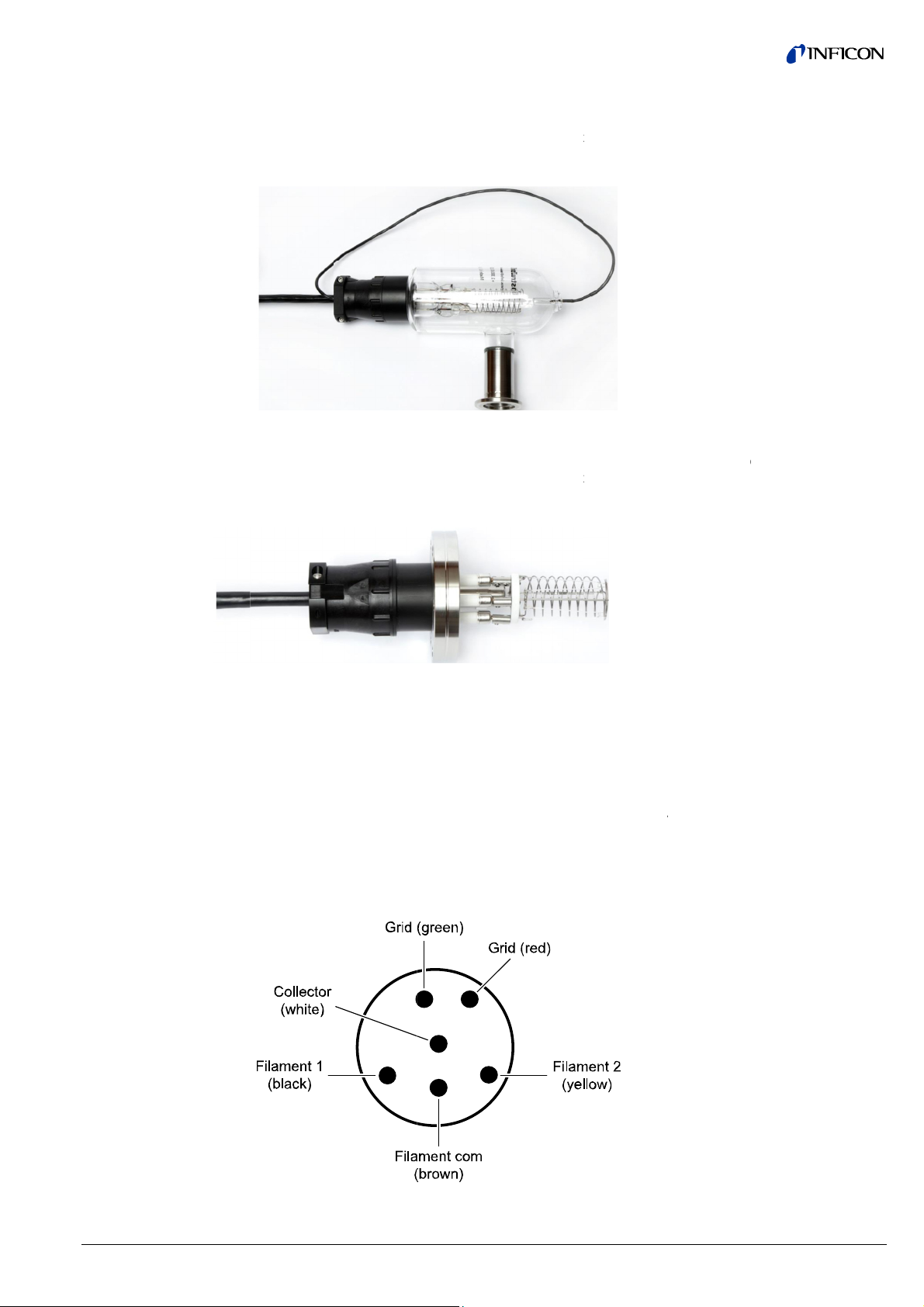
4.2.3.
Standar
Connect
I2R Deg
IG Cable
r Pin Out
ase View
BAG051
s - single fila
BAG051 or e
ent
uivalent nud
hanging cabl
i
not only bad
u
er of this eq
tuation, equi
s
CAUTIO
ent before c
he informatio
nnection of
lready have i
ith INFICON
c
ble with the
he pin-out of
auge cables
bles such as
e control unit
c
ntact no. 7 f
s
itch filament
ble and phy
d
sired to swit
I2R (resistiv
s from one d
electronics h
ipment, may
ment damag
! It is always
nnecting or d
presented i
B-A type ion
stalled on yo
roduct desig
GC083.
he CPC con
s shown belo
those for us
, e.g., the VG
r FIL2. This t
s from the co
ically remov
h filaments.
degas) B-A
evice to anot
ndling proce
lead to erron
and possibl
good industr
isconnecting
this section i
ization gauge
r vacuum ve
s, and you
ector used o
w. When usin
with controll
083, there i
pe of cable
trol unit - the
, rotate and r
Base
BAG0
I
R Degas - d
auge pin pat
er when pow
ure, it is not
ous measure
operator inju
practice to t
ables.
intended to
head or an I
sel which m
ish to continu
Granville-Ph
INFICON t
rs capable of
an additiona
nd control un
e is no need
connect the
iew
51
al filament
tern
er is applied t
dvised and,
ment results,
ry.
rn off power
address the i
cable that y
y not be dire
e using eithe
illips® and IN
o-filament s
switching th
l pin / socket
it will allow th
to go to the h
able connect
the module
f done by the
a hazardous
o the instru-
stallation /
u may
tly compatibl
that head /
ICON Ion
itch capable
filament fro
onnection at
user to
ad end of th
r when it is
22
tinb29e
(2016-11) VGC083A_B.
m
Page 23

4.2.4 Connecting the PGE050 connectors labeled "2"
and "3"
The view shown below is the CPC connector end of the IG cable:
VGC083 Connector End of Cable View
Pin/Socket
Contact
Description
(compatible with Granville-Phillips® ion gauge cables)
Number
1 Shield, chassis ground
7 FIL 2 (this contact is only present on dual filament IG cables
available from INFICON)
8 FIL COM
11 FIL 1
13 Grid Source (supply)
14 Grid return Used only for I2R degas design using the VGC083B
Not used for VGC083A EB-degas design
PN 399-580 … -582 are a custom cable assemblies provided in different lengths
from INFICON for connecting the VGC083 to INFICON PGE050 gauge or MKS
Instruments / Granville-Phillips® 275 Convectron® vacuum gauge sensor. Connect
the DE-9 D-subminiature connector to VGC083 and PGE050 connectors to "2" or
"3".
For your reference, the wiring chart for the PGE050 cable provided by INFICON is
shown below. In addition to INFICON provided standard cable assembly lengths,
INFICON will provide custom length cable assemblies upon request.
VGC083
pin no.
1
2
3
4
5
6
7
8
9
connects to PGE050 gauge pin no.
(INFICON molded, custom connector)
NC
cable shield
3
3
2
5
1
1
NC
tinb29e1 (2016-11) VGC083A_B.om 23
Page 24

4.2.5
o
n
o
e
e
r
T
o(P
c
A
e
R
Asiva
A
O
TINtaaAin
e
o
e
l
n
Y
o
a
p
b
u
g
o
e
a
p
r
t
P
a
8
t
y
h
h
t
t
a
aAna
d
f
e
V
o
d
C
n
p
e
a
o
d
b
s
l
s
Y
e
u
o
e
e
1
R
0
a
k
p
i
S
)
o
s
8
d
N
C
n
n
t
a
n
l
3
a
B
c
e
g
1
p
r
o
9
a
y
o
C
c
g
aCo
e
o
e
t
c
d
o
o
n
g
"
4.2.6
Power C
Relay Co
nnection
nection
he VGC083 r
e
ch 2-contact
the power c
t
N → 81).
Power
(
ontacts)
+
–
total of six s
p
luggable term
r
lay contactor
LY6. Each re
a
nd I (commo
LY1 thru RL
(contacts)
=
≠
I
quires an in
pluggable te
ntactors. Op
Con
Power input
tpoint relays
inal strip mati
s. The VGC0
lay has a con
).
Y6
Rela
ut power of 2
minal strip m
ional power s
tact Descripti
(20 … 28 V (
ower ground
re provided
ng connector
3 back pane
act labeled =
Contact De
Relay #1 to
(NORMAL
Relay #1 to
(NORMALLY
#1 to Relay
0 … 28 V (dc
ting connect
pplies are al
n
c), 200 W)
y the VGC0
are provide
relay connec
(Normally Op
cription
Relay #6
OPEN)
Relay #6
CLOSED)
#6 (COMMO
, 200 W to o
r is provided
o available f
Anal
Con
3. Two each
for easy con
tors are mark
en), ≠ (Norm
Rela
)
erate. One
for connectio
om INFICON
g Output
nectors
-contact
ection to the
ed RLY1 thru
lly Closed)
Connectors
4.2.7
4.2.8
Analog O
Connecti
Analog In
(Capacita
Gauges,
utput
n
put Conn
nce Diaph
tc.)
ction
agm
total of three
gnals are pro
cuum gauge
a
re provided f
p
nel analog o
h
s a contact l
O1 , AO2, A
(contacts)
+
–
ne analog in
his input can
FICON vacu
ct mating plu
nalog input c
1. Each conn
put ground)
A1
(
contacts)
+
–
D
analog outpu
portional to t
s. Three eac
r connection
utput connec
beled + (an
O3
An
ut is provide
be accepted
um module s
ggable termin
ntactor. The
ector has a c
nd D (power
A
Analog In
D
ts are provid
e displayed p
2-contact pl
o the analog
ors are mark
log output sig
Contact D
log Output #
log Output G
(Signal
by the VGC
rom one cap
ries PGE300
al strip conne
GC083 bac
ntact labeled
etect).
ontact Descri
alog Input (S
ut Ground (
tect (power d
d by the VG
ressure for a
ggable termi
utput contac
d AO1, AO2
nal) and – (a
scription
to #3 (Signa
ound #1 to #
eturn)
83 for using
citance diaph
PGE500 or
tor is provid
panel analo
+ (analog inp
tion
gnal)
ignal Return)
tect)
083. These
y of the user
al strip matin
tors. The VG
and AO3. Ea
alog output
An
l)
s an alternat
ragm gauge
AG302. On
d for connec
input conne
ut signal) an
An
utput voltage
assigned
connectors
083 back
h connector
round).
log Output
nnectors
gauge to "2
r other
each 3-conion to the
tor is marked
– (analog
alog Input
C
nnectors
.
24
tinb29e
(2016-11) VGC083A_B.
m
Page 25

When using a capacitance manometer / diaphragm gauge or INFICON modules
such as the PGE300, PGE500, BAG302 as an ALTERNATE GAUGE, the gauge
must be connected to the VGC083 as shown below. The alternate gauge must be
provided power from an auxiliary power supply capable of providing the power required by the alternate gauge connected to the VGC083. The D contact is used in
this configuration to protect the IG from being turned on at high pressure in case
power to the alternate gauge is lost.
4.2.9 Digital I/O Connection
Signal Type A - Control Input
Signals
Signal Type B - Status Output
Signal
Signal Type C - Status output
Signal
The IG can be controlled manually using the front panel soft-keys, via remote input
signals using the digital I/O connector or RS232/RS485 commands. The VCG083
can also be configured so that the IG sensor on/off is controlled by using the pressure measurements from CG1, CG2 or the alternate gauge. If the user prefers digital I/O as the means of controlling the IG, various control input and status output
signals are available from the 9-pin D-sub male DIGITAL I/O connector. The
DIGITAL I/O Connector also provides pin-pin compatible signals with the GP 358
vacuum gauge controller as well as compatible signals with the GP 307.
The DIGITAL I/O Connector provides three different types of signals as listed
below:
The IG sensor on/off, degas on/off and emission current selection can be set by
applying momentary continuity to ground. This requires a momentary ground of
less than 0.4 V (dc) at 10 µA for 25 msec (minimum) be applied. After this, the
input must be allowed to float higher than 3.5 V (dc) for 105 msec (minimum) before another low can be applied.
Input signal: Apply momentary continuity to ground to turn IG sensor on or off
Apply momentary continuity to ground to turn degas on or off
Apply momentary continuity to ground to switch Emission Currents
(100 μA or 4 mA)
The IG on/off status relay is also available as both normally open and normally
closed to indicate IG is on or off. This is an output signal to other external instruments to confirm IG filament is on or off. The IG on / off status relay is a single
pole, double-throw (SPDT) relay rated at 1.0 A, 30 V (dc) resistive or 1.0 A,
30 V (ac) non-inductive.
A degas status or an error condition output signal is also available from the
DIGITAL I/O Connector. If programmed for DEGAS STATUS, this can be used as
an output signal to other external instruments to confirm that degas is on or off. If
programmed for an error condition, this can be used as an output signal to other
external instruments to confirm whether any error conditions exist.
tinb29e1 (2016-11) VGC083A_B.om 25
Page 26

4.2.10 RS232 /
n
t
r
S5T
T
E
m9 R
T
m
a
a
y
=
=
p
n
d
i
o
o
s
d
s
o
o
o
h
m
h
s
t
.
o
.
r
c
e
s
n
d
n
D
a
y
y
a
w
n
r
p
b
n
o
o
n
n
p
h
e
o
d
y
C
y
o
o
t
s
G
r
a
o
o
b
a
/
o
t
m
c
n
c
s
s
m
a
n
o
r
n
p
t
D
1
V
n
/
e
R
c
a
e
V
i
h
n
E
2
o
f
Commu
Connec
RS485 Se
ications
ion
ial
ignal: Open c
mA IC max.
ransistor on
ransistor off
Pin
Descri
no.
1 IG Se
2 Groun
3 Emiss
4 IG on/
5 IG on/
Relay
6 Dega
7 Groun
8 Dega
9 IG on/
Relay
ither RS232
ands to/from
pole) connec
S485 serial c
p
rted.
1
. RS485 wit
derived fro
2
. RS232 wit
the same a
3
. RS232 pro
Controllers
4
. RS485prot
Controllers
he RS232 se
ale to female
p
rt. DO NOT
s
me time. Th
c
tions at the
ollector transi
Degas on or
Degas off or
9-
in (DE-9P)
ption
sor on/off
d
ion Current
ff Status rel
ff status rela
open = IG on
on/off
d
/error status,
ff status rela
closed = IG o
r RS485 seri
the VGC083.
tors that allo
ommunicatio
address, sta
the INFICO
start and sto
s the RS485
ocol compati
col compatib
ial port is co
, wired "pin-t
onnect both
VGC083 ca
ame time. O
stor (ground
error conditi
no error con
-subminiatu
y common
- Normally
Low = degas
- Normally
n
l communica
There are tw
independen
ports. Four
t and stop ch
N BAG302 I
p characters,
rotocol.
le with the G
le with the Gr
figured to all
- pin" to be c
f the RS232
not provide
ly one or the
mitter) rated
n exists,
ition exists
re DIGITAL I
losed
n or error
pen
ions may be
DE9 (D-sub
cable conne
erial commu
racters and
protocol.
but no addre
anville-Phillip
nville-Phillip
w, for exampl
nnected fro
and RS485 c
oth RS232 a
ther as prog
at 40 V max.
0 Connectio
Signal
Type
A
A
B
B
A
C
B
used to send
miniature, sh
tions to the
ication proto
ommand/res
sing is used.
s Series 307
Series 307
e, a 9-pin ext
the VGC083
bles to the
d RS485 ser
rammed by t
CE,
s
Digital I/O
Connector
receive com-
ll size E,
S232 and
ols are sup-
onse syntax
The syntax is
nd 358
nd 358
nsion cable,
to your serial
GC083 at the
al communie user.
An extensio
may be use
serial port on
our PC serial
cable wired
to connect t
the VGC083
port (a conve
in-to-pin
e RS232
directly to
rter may be
DE-9 Con
user su
communica
ectors for co
plied cables
ion port – D
E9S (RS23
nections to
or serial
9P (RS485),
)
ecessary).
26
tinb29e
(2016-11) VGC083A_B.
m
Page 27

o
c
E
c
E
S
d
D
u
3
E
D
)
u
3
E
a
c
u
c
C
C
C
9-c
ntact (DE-9
) D-submini
ture RS232
onnections
Socket
no.
1
2
3
4
5
6
7
8
9
Conne
AT TH
Pin
no.
1
2
3
4
5
6
7
8
9
Conne
AT TH
Description
No connect
Transmitte
Received
No connect
Signal Gro
No connect
No connect
No connect
No connect
t either RS2
SAME TIM
9-
pin (DE-9P)
Description
DATA A (–)
DATA B (+
No connect
No connect
No connect
Signal Gro
No connect
No connect
No connect
t either RS2
SAME TIM
ion
Data (OUT)
ata (IN)
ion
nd
ion
ion
ion
ion
2 or RS485
-subminiat
ion
ion
ion
nd
ion
ion
ion
2 or RS485
able to VG
re RS485 Co
able to VG
RS232
Connector
083 - DO NO
nnections
RS485
Connector
083 - DO NO
T CONNECT
T CONNECT
BOTH
BOTH
tinb29e1 (2016-11) VGC083A_B.om
27
Page 28

5 Operation - IG and CG
5.1 IG Emission Current
5.2 IG Degas
5.3 IG Filament Material
Selection / Venting the
Chamber
Yttria coated iridium filament
100 µA (0.1 mA), 4 mA, and 10 mA are available settings of emission current for
the hot cathode ion gauge.
1) In clean applications and when operating at higher pressure ranges
(5.00 × 10
-6
Torr to 1.00 × 10⁻³ Torr) the 100 µA emission setting is preferred.
2) At lower operating pressures (1.00 × 10⁻⁹ Torr to 5.00 × 10⁻⁴ Torr) the 4 mA
emission setting should be used.
3) Many vacuum measurement equipment users prefer to use the 10 mA emission
current setting when making measurements in the UHV pressure regime (below
1.00 × 10
-8
to 10
-11
Torr).
4) When using a diffusion pump or other pumps that use fluids, there is a possibility of the pump oil vapors entering the IG head. These vapors may form an
insulator on the internal components of the head which can lead to instability or
failure in controlling the emission. In this case, 4 mA and 10 mA emission
current may provide improved operating lifetime and measurement performance.
5) The emission current can also be set to automatically switch between 100 μA,
4 mA and 10 mA. This results in optimal and stable pressure readings over the
entire measurement range from low to high vacuum. For example, if an application requires that pressure measurements be performed by the ion gauge from
pressures lower than
-6
VGC083A: 5.00 × 10
VGC083B: 1.00 × 10
Torr up to 1.00 × 10⁻³ Torr
-6
Torr up to 1.00 × 10⁻³ Torr,
then the user may want to consider selecting the auto switching feature of the
emission current.
Electron bombardment degas (VC083A) or I2R resistive degas (VGC083B) is used
to rid a hot cathode ion gauge sensor of adsorbed gas. The intervals at which degas should be applied vary for each application. The low pressure measurement
performance of the head will normally improve after each degassing cycle.
• Degas can only be applied while the filament is turned on and operating.
• Ensure that the vacuum pressure is at or less than 5.00 × 10
-5
Torr before
attempting to initiate degas.
• Degas will automatically turn off after 10 minutes when using factory default
settings. Degas can be programmed for duration of 2 to 30 minutes.
• The VGC083 will continue to measure approximate pressure while degas is in
progress.
• Degas will automatically turn off if the pressure exceeds 1.00 × 10
-4
Torr during
the degas cycle, off but the filament will remain turned on.
• Degas can be interrupted by turning the IG filament off.
The choice of which filament to use is primarily dependent upon the process and
process gases the ion gauge will be used with. For general vacuum applications,
dual yttria coated filaments are offered for use with air and inert gases such as N2,
argon, etc. Optional dual tungsten filaments are available for use with gases that
are not compatible with yttria coated iridium filaments.
In most general vacuum applications, the yttria coated iridium filament is the best
choice.
Yttria coated iridium filaments typically operate at a lower temperature than tungsten filaments and thus have a lower outgassing rate at UHV and lower chemical
reactivity with active gases. Yttria coated iridium filaments typically have a longer
operating life than tungsten filaments in clean applications.
28
tinb29e1 (2016-11) VGC083A_B.om
Page 29

Tungsten filament
NOTICE
NOTE
5.4 IG Over Pressure Shut
Down
5.5 IG Over Temperature
Shut Down
The yttria coated filament can survive occasional accidental start attempts at atmosphere in air, but the overall life of the filament may be shortened during each
occurrence. Good vacuum practice is to use a separate pressure gauge such as
INFICON's PGE050 convection gauge to know when to turn on the ion gauge filament.
Typically, a bare tungsten filament is a better choice in those applications where an
yttria coated filament is quickly damaged due to the gas type in use. For example,
processes such as ion implantation may only use tungsten filaments. Be aware that
corrosive applications are hard on any filament and filament life will be shortened
while operating in such environments. Tungsten filaments are easily damaged by
exposure to air/oxygen during accidental system vents or if considerable quantities
of water vapor are outgassed during pump-down and bake-out. It is very important
to make sure the tungsten filament is turned off before bringing the chamber up to
atmosphere, especially if air is being used to vent the chamber. The use of pure N2
gas is highly recommended to vent or purge your vacuum chamber. Testing has
shown that tungsten filaments can withstand limited high pressure excursions when
is present.
only N
2
Venting with air or other gases containing oxygen can damage the tungsten filaments. If you try to turn on an ion gauge with tungsten filaments while it is sitting on
your desk exposed to room air, you will immediately damage or destroy the filament beyond repair.
Do not use another gauge to automatically turn off the ion gauge when the ion
gauge (IG) filament in use is constructed of tungsten (yttria coated filament is ok).
The response time of other gauges may not allow for timely turn off of the tungsten
filament leading to filament damage. Always turn off the IG filament manually before pressure is allowed to rise above 1.00 × 10⁻³ Torr.
Both types of filaments will suffer eventual damage if operated at high pressures.
The type and amount of damage at high pressure is dependent upon the length of
operating time, the pressure and the gas present.
The VGC083 is provided with factory set default values for over pressure shut
down. The IG will shut off automatically should the pressure reach or rise above
the pressure shut down values shown below:
Factory set IG overpressure shut down values
Emission Current Overpressure Shut Down
Torr mbar Pa
100 µA (0.1 mA) 1.00 × 10⁻³ 1.33 × 10⁻³ 1.33 × 10⁻¹
4 mA 5.00 × 10⁻⁴ 6.65 × 10⁻⁴ 6.65 × 10⁻²
10 mA 1.00 × 10⁻⁴ 1.33 × 10⁻⁴ 1.33 × 10⁻²
An over temperature condition may result inside the VGC083 controller when using
an ion gauge cable longer than 50 ft. When this over temperature condition exits
and if degas is on, the controller will automatically turn off degas first. If the temperature inside the controller continues to climb, the controller will then turn off the IG
filament and an "OVER TEMP" message will appear on the programming & setup
screen. When this extreme condition exists, the VGC083 may need airflow around
it to prevent the over temperature shut down.
tinb29e1 (2016-11) VGC083A_B.om 29
Page 30

5.6 Convection Gauge (CG)
Initial Setup
Setting Zero (SET VAC)
Setting Atmosphere (SET ATM)
NOTE
Two of the most important steps for the initial setup of the convection gauges are to
set zero (SET VAC) and set atmosphere (SET ATM) as described in the CONVEC
GAUGE section 6.5.3. This will ensure proper operation of the gauge and accurate
pressure measurements. The gauge is calibrated at the factory using nitrogen. Furthermore, the gauge is also installed in a certain orientation when calibrated at the
factory. Without setting zero and atmosphere after the gauge is installed in your
system, the gauge may not display the expected and correct pressures. This could
be caused by the fact that you may be using a different gas than Nitrogen such as
air to setup and calibrate the gauge (most commonly the case) and the gauge
orientation is different than the orientation used at the factory. As such, it is very
important to perform your own initial setup and calibration by setting zero and atmosphere with the gauge installed in your actual system. Please note the following:
Setting zero optimizes performance of the gauge when operating at a low pressure
range of 1.00 × 10
higher than 1.00 × 10
-4
Torr to 1.00 × 10⁻³ Torr. If your minimum operating pressure is
-3
Torr, it is not normally necessary to set zero and thus setting atmosphere should be adequate. If you are able to evacuate your system to
below 1.00 × 10⁻⁴ Torr, it is always a good practice to check and set zero if necessary. See "SET VAC CG1" or SET "VAC CG2" in CONVEC GAUGE section 6.5.3.
Setting atmosphere is the most important step for a newly installed gauge. If you
prefer to use air to set atmosphere, vent your vacuum system chamber to expose
the gauge to the local atmospheric pressure (air) and set atmosphere to match
your known local uncorrected barometric pressure (air). This is the reading of
ambient air pressure you will expect if you were to vent and open your vacuum
chamber to the atmosphere surrounding the outside of your chamber. At sea level,
this pressure is usually near 760 Torr. At elevations above sea level, the pressure
decreases. Check your local aviation authority or airport web sites or your current
local weather conditions online to help find your local uncorrected barometric pressure if you do not have this information. See "SET ATM CG1" or "SET ATM CG2"
CONVEC GAUGE section 6.5.3.
Setting zero and atmosphere is normally required only once during the initial setup
and maybe checked by the user periodically. After power has been applied to the
gauge during the initial setup, allow five minutes for the gauge to stabilize (warmup) before setting zero and atmosphere.
The information presented in sections 5.1 through 5.6, above, is intended as an
introduction to the programming capabilities of the VGC083 for use in controlling
the selectable parameters and functions of the BAG050 IG (VGC083A), BAG051,
BAG052/053 IG (VGC083B) and PGE050 heads.
30
tinb29e1 (2016-11) VGC083A_B.om
Page 31

p
y
t
y
y
y
o
e
s
y
y
M
y
c
y
C
a
d
i
a
t
t
e
o
A
e
e
e
e
n
a
u
e
s
e
G
T
e
e
G
t
p
d
t
5
t
t
t
f
d
m
a
s
p
A
s
e
n
w
n
r
p
g
i
m
p
n
s
6 Setu
6.1 Appl
6.2 Fron
Displa
ment
Displa
Displa
and pr
ing Pow
Panel Di
- Pressure
- Units of
- Setup S
gramm
r
play
Measure-
easure
reen
ing
Before
the VG
nected
The VG
• d
• d
• d
A white
uremen
front pa
The VG
screen.
convec
cators,
screen.
ou turn on p
083 to the B
nd secured.
C083 provid
isplay repres
hea
(IG).
splay repres
(CG
1).
isplay repres
an
lternate gaug
LED is illumi
ts in Torr, mb
nel; millibars
C083 provid
This screen i
ion vacuum g
mission curr
wer to the V
G05x nude I
urn on pow
s three indep
nts pressure
nts pressure
nts pressure
e (CG2 or C
ated next to
r or Pa (the
nit is written
s an indepen
used for set
auges. Other
nt and selec
C083 for the
and PGE0
r by pressing
ndent front p
measuremen
easuremen
measuremen
2-ALT).
he selected e
ascals unit o
s mbar).
ent setup an
up, program
useful inform
ed IG filamen
first time, en
0 convection
the Power ke
anel LED dis
s from the B
s from the fir
s from the s
ngineering u
measure is
programmi
ing and ope
tion such as
t are also dis
ure the cable
gauges are c
y.
lays:
G05x hot ion
t convection
cond convect
it indicating
ritten as 'Pa'
g OLED setu
ation of the io
relay status i
layed in the
s from
on-
gauge
auge
on or
eas-
on the
n and
dietup
tinb29e1 (2016-11) VGC0
83A_B.om
31
Page 32

6.3
U
F
P
S
f
e
r
T
c
T
Vid
Tse
oseth
Trara"N
Tsc
s
p
u
a
r
a
n
r
e
c
"
r
s
c
o
A
G
G
U
S
e
k
s
s
s
s
p
a
s
e
,
a
o
=
F
d
e
o
a
8
w
s
s
k
p
t
h
u
a
n
s
V
]
R
A
s
o
8
e
r
s
s
e
O
m
a
t
n
u
S
1
e
n
W
E
K
n
t
n
e
h
C
U
o
e
ser Inter
ace Basi
s
he setup and
ramming-key
g
GC083 front
entify what f
o begin progr
lect the desi
a
cess the par
t
the previous
tting additio
e desired pa
programming
located belo
anel. During
nction each
amming, pre
ed menu and
ameters and
menu or pre
al parameter
ameter then
of the VGC0
the OLED
programming
ey represent
s the MENU
change the
ave the new
s repeatedly
, scroll with t
ress ENTER
3 controller i
etup screen
of the VGC0
.
ey. Press th
arameters. P
ettings. Pre
o return to th
e UP and D
done via th
n the left ha
3, the OLED
UP and DO
ess the ENT
s the MENU
e main scree
WN keys un
four prod side of the
display will
N key to
R key to
ey to return
. To continu
il you reach
6.4
actory-S
aramete
ETUP UNI
t Default
s
NOTE
he value of c
nge or limit. I
nge of a spe
O CHANGE
a
nd enter a co
he following i
reen menu.
UNITS [Fa
•
INFO [Fact
•
•
SET CG2-
•
ALT GAU
ALT GAU
•
•
I - O STAT
•
DEFAULT
(not useabl
rtain menu p
f the user trie
ific menu, th
. In this case
rect value th
a summary
tory default
ry default =
LT [Factory
E [Factory d
E CAL [Fact
S [Factory d
[Factory def
e if IG sensor
rameters m
to program
setup scree
the user nee
t is within the
f all factory-
TORR]
IRMWARE
efault = CG2
fault = 10 TO
ry default = F
fault =DEG
ult = PRESS
is on)]
st be progra
value that is
will moment
s to access
allowable ra
et default val
ERSION]
R CDG]
ctory Set Nu
S STATUS]
ENTER TO
med within a
outside of th
arily display t
he specific m
ge.
es in the VG
mber]
ET OR MEN
allowable
allowable
e message
enu again,
083 setup
TO EXIT
32
tinb29e
(2016-11) VGC083A_B.
m
Page 33

ION GAUGE
CONVEC GAUGE
RELAYS
ANALOG OUTPUT
SERIAL COMM
• EMISS SELECT [Factory default = IE = 100UA]
• AUTO IE1 TRIP [Factory default = DISABLED]
• AUTO IE2 TRIP [Factory default = DISABLED]
• SELECT FIL [Factory default = FILAMENT 1]
• DEGAS TIME [Factory default = 10 MINUTES]
• SENSITIVITY [Factory default = 25.00]
• OVER PRES 100 [Factory default = 1.00E-03]
• IG TRIP PRESSURE [Factory default = 1.00E-03]
• IG CONTROL [Factory default = MANUAL MODE]
• CAL FACTORS [Factory default = C0, C1, C2, C3, C4, C5 all factory-set to 50]
(VGC083A only)
• SET VAC CG1 [Factory default = 0.00E 00]
• SET ATM CG1 [Factory default = 7.60E 02 TORR]
• SET VAC CG2 [Factory default = 0.00E 00]
• SET ATM CG2 [Factory default = 7.60E 02 TORR]
• ASSIGN REL 1 [Factory default =ION GAUGE]
• ASSIGN REL 2 [Factory default =CG1]
• ASSIGN REL 3 [Factory default =CG2]
• ASSIGN REL 4 [Factory default =ION GAUGE]
• ASSIGN REL 5 [Factory default =CG1]
• ASSIGN REL 6 [Factory default =CG2]
• REL 1 LO TRIP [Factory default = 1.00E-06]
• REL 1 HI TRIP [Factory default = 2.00E-06]
• REL 2 LO TRIP [Factory default = 1.00E-01]
• REL 2 HI TRIP [Factory default = 2.00E-01]
• REL 3 LO TRIP [Factory default = 1.00E-01]
• REL 3 HI TRIP [Factory default = 2.00E-01]
• REL 4 LO TRIP [Factory default = 1.00E-06]
• REL 4 HI TRIP [Factory default = 2.00E-06]
• REL 5 LO TRIP [Factory default = 1.00E-01]
• REL 5 HI TRIP [Factory default = 2.00E-01]
• REL 6 LO TRIP [Factory default = 1.00E-01]
• REL 6 HI TRIP [Factory default = 2.00E-01]
• TEST RELAYS
• ANALOG OUT 1 [Factory default = IG - CG1 0.5 - 7V]
• ANALOG OUT 2 [Factory default = CG1 1 - 8 V ]
• ANALOG OUT 3 [Factory default = CG2 1 - 8 V ]
• AOUT CAL 1 [Factory default = Factory Set Number]
• AOUT CAL 2 [Factory default = Factory Set Number]
• AOUT CAL 3 [Factory default = Factory Set Number]
• AOUT LIN 1 [Factory default = 1.00E 00]
• AOUT LIN 2 [Factory default = 1.00E 00]
• AOUT LIN 3 [Factory default = 1.00E 00]
• COMM TYPE [Factory default = RS485]
• BAUDRATE [Factory default = 19200 BAUD]
• FRAMING [Factory default = 8 BITS NONE 1]
• ADDRESS [Factory default = 01]
tinb29e1 (2016-11) VGC083A_B.om 33
Page 34

DISPLAY
6.5 Programming
6.5.1 SETUP UNIT
UNITS
INFO
SET CG2 - ALT
ALT GAUGE
• SCREEN SETUP [Factory default = NORMAL]
• SCREEN SAVER [Factory default = ON]
• BRIGHTNESS [Factory default = 0]
This section provides detailed information on programming and configuration of
various menus and submenus of the device.
This key, on the VGC083 front panel, is referred to as the 'ENTER'
key throughout this manual.
From the main menu (press the MENU key if the main menu is not shown), scroll
Up or Down to SETUP UNIT then press the ENTER key to access the SETUP
UNIT menu for configuring the VGC083 general parameters such as the units of
measure, selecting CG2 verses ALTERNATE GAUGE, etc. In certain instances,
during setup of the programmed functions and settings, you may need to press the
ENTER key until you reach the end of a program/setup sequence before pressing
the MENU key to return to the main menu or previous setup screen.
[Factory default = TORR]
This allows the user to display the pressure measurements in Torr, mbar or
pascals. The user must program all other programming values according to their
requirements.
[Factory default = FIRMWARE VERSION]
Provides the model number of VGC083, the firmware version numbers for both the
VGC083 controller and the IG connected to it.
[Factory default = CG2]
This allows the user to assign the type of gauge to the CG2/ALT display. The user
can either assign a second convection gauge CG2 (same type as CG1 using
INFICON's PGE050 convection gauge sensor) or analog input using a 0-10 V (dc)
analog input signal from an alternate gauge. The ANALOG INPUT selection allows
processing of one analog input voltage signal from other gauges such as a capacitance diaphragm gauge or INFICON vacuum gauge modules PGE300, PGE500 or
BAG302.
[Factory default = 10 TORR CDG]
Ignore this menu if you have selected CG2 in the SET CG2 - ALT menu above. If
you have selected ANALOG INPUT in the SET CG2 - ALT menu above, the ALT
GAUGE menu selection is used to assign the type of alternate gauge.
• Select 100 mTORR CDG for a 100 mTorr Capacitance Manometer / Diaphragm
Gauge (CDG) with 0-10 Vdc analog output.
• Select 1 TORR CDG for a 1 Torr CDG with 0-10 Vdc analog output.
• Select 10 TORR CDG for a 10 Torr CDG with 0-10 Vdc analog output.
• Select 100 TORR CDG for a 100 Torr CDG with 0-10 Vdc analog output.
• Select 1000 TORR CDG for a 1000 Torr CDG with 0-10 Vdc analog output.
• Select ITI LOG CG if you are using INFICON's convection gauge modules such
as the PGE300 or PGE500 with a Log-linear analog output.
• Select ITI LOG IG if you are using INFICON's ionization gauge module such as
the BAG302 IG with a Log-linear analog output.
• Select ITI NON-LINEA if you are using INFICON's convection gauge modules
such as the PGE300 or PGE500 with a non-linear analog output.
34
tinb29e1 (2016-11) VGC083A_B.om
Page 35

ALT GAUGE CAL
- I - O STATUS
DEFAULTS
6.5.2 ION GAUGE
NOTE
NOTICE
[Factory default = Factory Set Number]
Ignore this menu if you have selected CG2 in the SET CG2 - ALT menu above. If
you have selected ANALOG INPUT in the SET CG2 - ALT menu above, the ALT
GAUGE CAL menu selection is used to optimize the analog input calibration. It is
recommended that the user not make this adjustment unless the displayed alternate gauge pressure (CG2/ALT display channel) do not closely match the expected
pressure from the analog input calculations.
Example - To perform ALT GAUGE CAL if ALT GAUGE menu is selected for a
1000 TORR CDG. Connect both the CDG and a high resolution voltmeter to the +
and – terminals of the VGC083 Analog Input Connector labeled AI. With CDG
exposed to atmosphere, measure the analog input from the CDG at the VGC083
Analog Input Connector and calculate the corresponding pressure. In the ALT
GAUGE CAL screen use the UP or DOWN keys to adjust the displayed pressure
by the VGC083 to match the calculated pressure from the CDG analog signal. For
example, if the analog input signal from the CDG is at 7.600 volts representing
760 Torr for a 1000 TORR CDG, then adjust the ALT GAUGE CAL so that the
VGC083 also displays 760 Torr. For other CDG ranges always use CDG's full
scale pressure value to perform calibration. For example, if you are using a
100 TORR CDG, evacuate your system pressure to 100 Torr and use the same
calibration procedure above.
Example - To perform ALT GAUGE CAL if ALT GAUGE menu is selected for ITI
LOG CG, ITI LOG IG or ITI NON-LINE. When using other INFICON vacuum gauge
modules such as PGE300, PGE500 or BAG302 as alternate gauges to CG2, the
analog output signals from these devices can be used to display pressure in the
CG2/ALT display channel. Connect the analog output from these devices to the +
and – terminals of the VGC083 Analog Input Connector labeled AI. In the ALT
GAUGE CAL screen use the UP or DOWN keys to adjust the displayed pressure
by the VGC083 to match the pressure reading on the modules.
As you adjust the analog output, the number being displayed in the ALT GAUGE
CAL screen represents the millivolts offset from zero volts that is being used internally for the analog input gain adjustment.
[Factory default = DEGAS STATUS]
A degas status or an error condition output signal is available from the DIGITAL I/O
connector. If selected for DEGAS STATUS, this can be used as an output signal to
other external instruments to confirm that degas is on or off. If selected for ERROR
STATUS, this can be used as an output signal to other external instruments to confirm whether there is an error condition.
[Factory default = PRESS ENTER TO SET OR MENU TO EXIT]
The system can be returned to the original factory settings by using the ENTER
key to set factory defaults. The IG filament must be off (sensors off) in order to
reset defaults.
If you reset all values to original factory default settings, you would need to repeat
the initial setup procedure for the convection gauges as described in section 5.6
and reprogram other parameters as required.
Before you activate the ion gauge/filament, make sure you understand all instructions and information provided in this manual and the Operating Manual for the
PGE050 convection gauge. Furthermore, you should ensure you have fully configured the VGC083 control unit to your operational requirements before turning the
filaments on. Prior to turning on the ion gauge filament you should ensure the pressure is below 1.00E-03 Torr (1 mTorr) with emission current set at 100 μA;
5.00E-04 Torr with emission current set at 4 mA and 1.00E-04 Torr with emission
current set at 10 mA.
tinb29e1 (2016-11) VGC083A_B.om 35
Page 36

EMISS SE
L
A
T
oof(y
u
FUAtiocuIEsw
ntosu
Mcu1Aswsu
Sbm
wpSswthto
ufintrth
a
w
F
T
T
e
osu
hto
N
s
g
r
y
e
o
d
4
h
w
e
h
a
o
m
0
n
o
E
c
n
E
n
m
o
a
a
l
i
r
l
n
e
t
E
o
r
m
o
e
r
o
r
x
o
e
u
b
A
o
0
A
s
t
o
u
A
0
t
e
F
d
r
o
w
E
o
s
s
f
m
e
o
s
o
w
0
C
r
m
U
A
h
u
m
e
d
t
3
A
e
o
m
c
o
a
t
e
s
n
r
.
n
e
a
o
m
u
h
.
d
T
a
s
e
n
S
e
n
P
r
E
o
t
e
c
m
n
e
t
t
u
o
n
n
g
e
b
r
o
0
c
e
,
a
t
e
r
f
m
4
a
L
i
T
d
e
f
o
A
o
n
1
t
m
o
p
l
A
g
e
0
e
r
o
o
o
A
o
a
m
p
c
T
p
d
t
a
0
U
a
o
A
o
w
a
d
n
e
h
e
o
o
o
s
r
T
e
o
-
e
r
-
h
p
y
y
-
UTO IE1
ECT
RIP
NOTE
CAUTIO
t
oxidizing ga
f the ion gau
ttria coated i
a
llow for timel
ngsten filam
t
p
ressure is all
[
actory defaul
se the Up an
UTO IE 100-
n of 100 μA,
rrent throug
100-10 allo
itching of th
u
rement range
tails about t
d
clean applic
I
1.00E-03 T
res (1.00E-0
any vacuum
rrent setting
.00E-08 to 1.
s described p
itch betwee
re readings
elect AUTO I
tween 100 μ
easurements
.00E-03 Torr,
1
utomatic swit
a
hich the emis
rogrammed i
elect AUTO I
itch betwee
at pressure
1.00E-03 T
1
0-10 autom
re trip point
s
ed by the va
ip point at wh
e value prog
If
you plan to u
z
tion gauge fi
h
ve 100 μA a
1
mA emissio
s
itching featu
g
uge and op
[
actory defaul
he default se
1
0 μA. If the
RIP value pr
l
ct the pressu
4
mA. For exa
n gauge will
i
rement rang
a
utomatically s
t
e choice of p
1.00E-04 T
! Due to the
es or gas mi
e when the i
idium filamen
turn off of th
nts. Always t
wed to rise a
t = IE = 100U
Down key t
, AUTO IE 1
4 mA, 10 m
out the mea
s for automa
emission cu
requires vari
e emission c
tions and wh
rr) the 100 μ
9 Torr to 5.0
measuremen
when making
0E-11 Torr).
reviously, the
100 μA, 4 m
ver the entir
100-4 if you
A and 4 mA.
be performe
then the use
hing feature
sion current
the AUTO I
100-10 if y
100 μA, 4 m
easurement
rr, then the u
tic switching
t which the e
lue program
ich the emissi
ammed in th
se a convecti
lament on/off
nd 4 mA emi
n current). H
re here, you
rate at the 1
t = 1.00E-05]
ting is DISAB
MISS SELE
grammed he
re at which e
ple, if the A
perate at the
of 1.00E-03
witch to 4 m
rogramming t
rr.
isk of filamen
tures, never
n gauge fila
t is okay). Th
filament lea
rn the tungs
ove 1.00E-0
]
select emiss
0-10. Then p
results in op
urement rang
ic switching
rent is reco
us emission
rrent selecti
en operating
emission se
E-04 Torr) th
equipment u
measureme
emission cur
A and 10 mA
measureme
would like th
or example,
by the ion g
may want to
f the emissi
ill switch fro
1 TRIP men
u would like t
A and 10 mA
be performe
er may want
eature of the
mission curre
ed in the AU
on current wil
AUTO IE2 T
n gauge or
function (see
sion current
wever by sel
ould be able
mA emissio
LED if EMIS
T menu is s
e (Factory de
ission curre
TO IE1 TRI
emission cur
Torr to 1.00
at pressure
e AUTO IE1
failure caus
se another g
ent in use is
response ti
ing to filame
n IG filamen
Torr.
ion current to
ess ENTER
ration of the
e. Selection
f the emissio
mended whe
urrent settin
n.
t higher pres
ting is preferr
4 mA emissi
ers prefer to
ts in the UHV
ent can also
This results i
t range from
emission cu
f an applicati
uge from 5.0
consider sele
n current. Th
100 μA to 4
below.
e emission c
For example
by the ion g
o consider s
emission cur
t will switch
O IE1 TRIP
l switch from
IP menu bel
n alternate g
IG CONTRO
elections ava
cting the AU
to use these
current as w
SELECT me
t to AUTO IE
ault = 1.00E-
t automaticall
value is set t
ent of 100 μ
-05 Torr. The
f 1.00E-05 T
TRIP point a
d by inadver
auge to auto
constructed
e of other ga
t damage es
t OFF manua
100 μA, 4 m
o save settin
nit with a fix
f AUTO IE 1
current. Th
the user’s p
s. See secti
sure ranges (
ed. At lower
on setting sh
use the 10 m
pressure reg
be set to aut
n optimal and
low to high v
rrent to auto
n requires th
0E-07 Torr u
ting the AU
pressure tri
mA is define
urrent to auto
, if an applica
uge from 4.
lecting the A
ent. In this c
rom 100 μA t
enu below a
mA to 10 m
ow.
uge to contr
menu belo
ilable (not av
O IE 100-10
evices to co
ll.
nu above is s
100-4, then t
05) allows th
y switches fr
1.00E-05 T
over the pre
emission cur
rr or lower.
ywhere betw
ent exposure
atically turn
f tungsten
uges may not
ecially for
ly before
, 10 mA,
. The selec-
d emission
0-4 or AUTO
automatic
essure meas
n 5.1 for mor
5.00E-06 Tor
perating pres
uld be used.
emission
ime (below
matically
stable pres-
cuum.
atically switc
at pressure
to
O IE 100-4
point at
by the value
matically
ion requires
0E-10 Torr u
TO IE
se, the pres-
4 mA is de-
nd pressure
is defined b
l the ioni-
), you will onl
ilable with
automatic
trol the ion
t to 4 mA or
e AUTO IE1
user to sem 100 μA to
rr, then the
sure meaent will then
he user has
en 1.00E-06
36
tinb29e
(2016-11) VGC083A_B.
m
Page 37

AUTO
SEL
E
S
G
y
a
g
m
w
T
b
e
s
y
t
h
t
n
i
t
v
y
g
a
y
g
a
2
T
v
o
e
P
i
e
s
e
h
c
A
r
e
s
0
m
w
e
A
m
E
0
A
L
l
n
t
o
.
f
d
d
f
t
(
w
e
f
h
G
u
r
c
n
c
n
s
I
c
p
-
s
m
p
u
o
o
e
V
g
p
c
t
u
r
s
-
s
a
g
r
e
E
U
m
e
v
t
t
R
h
t
e
e
o
e
n
n
G
r
m
c
d
g
e
e
t
t
i
e
o
0
o
c
0
7
1
2
M
r
m
a
m
o
p
d
n
t
e
h
b
h
o
T
c
n
p
t
r
U
t
m
h
e
m
r
T
b
a
h
r
g
g
e
a
g
o
e
e
o
n
p
n
m
F
n
o
DEG
SEN
IE2 TRIP
CT FIL
AS TIME
ITIVITY (V
NOTIC
C083A)
[Factor
The def
100 μA.
TRIP v
lect the
10 mA.
ion gau
progra
current
lower.
where
is set to
gramm
switche
[Factor
Allows
It is hig
filamen
an exte
tain em
filamen
that ha
[Factor
The len
cycle c
[Factor
The len
cycle c
When u
tivity to
25 per
Sensiti
based
measur
Ic = P ×
where
emissio
1)
Sens
creat
emis
the r
reac
Typi
default = 1.
ault setting is
If the EMISS
lue program
pressure at
For example,
e will operat
med for the
will then auto
he user has t
etween 1.00
AUTO IE 10
d to select th
from 100 μ
default = FI
he user to se
ly recomme
s are the coa
ded period
ssion current
coating may
e outgassed
default = 10
th of time, in
n be selecte
default = 25.
th of time, in
n be selecte
sing the BAG
25 per Torr. I
orr, you may
ity constant u
n the followin
ment:
S × I
e
is Pressure,
n current.
itivity for the B-A
d and collected
ion current from
adout of pressur
us@inficon.com
al sensitivity for t
0E-07]
DISABLED if
SELECT me
ed here (Fa
hich emissio
if the AUTO I
at the emis
UTO IE1 TR
atically swit
he choice of
-06 to 1.00E
-10, then the
e desired pre
to 4 mA.
AMENT 1]
ect which fila
ded to period
ed iridium ty
f time can ca
This will bec
become pois
rom the proc
MINUTES]
minutes, deg
from 2 to 30
00]
minutes, deg
from 2 to 30
050 nude UH
you are usin
set the actua
sed by the o
g mathemati
S is Sensitivi
ype ionization ga
collector current)
hich the ion cur
when measured
or further discus
e nude UHV EB
EMISS SEL
u is set to A
tory default =
current auto
E2 TRIP valu
ion current of
P menu abo
h to 10 mA a
rogramming
08 Torr. Note
AUTO IE1 T
sure at whic
ent to opera
cally alternat
e. An inactiv
se failure of t
me more pr
ned by proc
ss materials.
ssing will ru
minutes in du
ssing will ru
minutes in du
EB-degas I
an IG with a
sensitivity fo
erating syste
al formula for
1)
; Ic is the
ge is a constant.
per unit measure
ent is generated.
by the ion gauge
ion on the use of
egas ionization
CT menu ab
TO IE 100-1
1.00E-07) all
atically swit
is set to 1.0
4 mA from th
e to 1.00E-0
t pressure of
he AUTO IE
that if the E
IP value abo
emission cu
te: either Fila
operating fil
, coated fila
hat filament t
blematic in a
ss gas bypro
after it is init
ration.
after it is init
ration.
or equivale
known sensi
r the IG head
for the pres
the B-A ion g
ollector curre
A number defin
of pressure per t
This setting can
for gases other t
this setting for c
auge used is 25
ve is set to 4
, then the A
ws the user
hes from 4
E-07 Torr, t
trip pressur
Torr. The e
.00E-07 Tor
TRIP point a
ISS SELEC
ve must still
rent automati
ent 1 or Fila
ments 1 and
ent not oper
establish an
plications w
ucts or mate
iated. The de
iated. The de
t nude IG, s
ivity other th
you are usin
ure calculati
auge pressur
t and Ie is th
d as the quantity
e controlled qua
e useful for com
an nitrogen/air.
mpensated readi
per torr (25 Torr
mA or
TO IE2
o seA to
en the
value
ission
or
ny menu
e pro-
cally
ment 2.
2 if the
ted for
d main-
ere the
ials
as
as
t sensin
. The
n is
f ions
tity of
ensating
Consult
gs.
-
1
).
C
UTION! The
a value
to ensu
is used
damag
as a re
tinb29e1 (2016-11) VGC0
83A_B.om
not matching
e that the V
with may res
due to incor
ult of incorre
user assume
the actual he
C083A is pro
lt in pressure
ect pressure
t pressure m
all risks if th
d (sensor) s
rammed for
readings tha
eadings and
asurement r
SENSITIVI
nsitivity des
he actual se
are not true
improper sys
adings may
Y is program
ribed above.
sitivity of the
ressure. Equ
em control fu
esult.
ed to
ailure
head it
ipment
ctions
37
Page 38

SENSITIVI
T
E
R
O
3
F
W
othbm
c
w
ois
FTw
Tis
c
mof
T
a
F
T
seS
A
T
eyogm
T
x
F
T
G
Sth
e
a
s
y
o
s
n
t
o
e
o
v
N
t
a
o
n
l
s
u
w
(
e
A
o
u
w
n
o
e
n
T
b
T
0
i
l
r
n
A
h
I
n
I
t
e
e
z
e
m
r
v
s
B
e
s
r
s
n
e
r
a
h
n
s
t
m
u
e
v
s
a
c
e
s
c
r
o
d
v
i
a
c
g
y
c
m
n
o
e
k
n
e
g
g
m
e
0
d
r
p
o
e
e
c
s
O
s
s
e
e
G
-
e
n
e
U
B
n
b
r
e
u
s
n
S
y
u
e
c
u
o
g
u
0
o
a
l
s
w
o
E
a
a
e
o
o
C
e
f
1
q
y
o
f
I
q
g
e
o
y
r
n
w
u
d
m
d
p
o
h
G
T
u
a
G
o
t
G
t
n
o
r
d
n
e
e
w
n
n
Y (VGC08
B)
[
actory defaul
hen using th
g
lass enclosed
y
u are using
e actual sen
the operatin
athematical f
I
= P × S × Ie
here P is Pre
e
mission curre
1)
Sensitivity for
created and c
emission curr
the readout of
reachus@infic
Typical sensiti
t = 10.00]
resistive or
IG (BAG052
n IG with a k
itivity for the
g system for
ormula for th
ssure, S is S
nt.
he B-A type ioni
llected (collector
nt from which th
pressure when
on.com for furthe
ity for the resisti
2
R degas nu
/ 053, or equi
own sensitiv
G head you
he pressure
B-A ion gau
nsitivit
ation gauge is a
current) per unit
ion current is ge
easured by the i
discussion on th
1)
; Ic i
e or I2R degas io
e IG (Series
alent) set se
ty other than
re using. The
alculation is
e pressure m
the collecto
onstant. A numb
easure of press
erated. This setti
n gauge for gase
use of this setti
ization gauges u
AG051, or e
nsitivity to 10
10 per Torr,
Sensitivity c
ased on the
easurement:
current and
r defined as the
re per the contro
ng can be useful
other than nitro
g for compensat
sed is 10 per torr
uivalent) or
per Torr. If
ou may set
nstant used
ollowing
is the
e
uantity of ions
lled quantity of
for compensating
en/air. Consult
d readings.
-1).
(10 Tor
OVER PR
IG TRIP P
IG CONTR
S 100
ES
OL
NOTE
CAUTIO
a
value not ma
t
ensure that
used with m
d
mage due t
a result of i
a
[
actory defaul
his function a
hen the emis
he overpress
100 μA. Ho
1
.00E-03 Torr
fi
ations to det
easuring (B
1.00E-03 T
he overpress
1
.00E-04 Torr
nnot be cha
c
[
actory defaul
his setting all
a
lternate gaug
i
operating at
mission curre
ELECT = AU
LT GAUGE.
he IG TRIP P
.00E-03 Torr
1
tting the IG
s
ur ion gauge
uge head is
easuring a m
he user does
mA or 10 em
4
ed at 5.00E-
fi
1
mA respect
[
actory defaul
his function a
b
controlled f
AUGE (alter
elect MANU
e ion gauge
! The user a
tching the act
he VGC083
y result in pr
incorrect pre
correct pres
t = 1.00E-03]
llows the use
ion current i
re shut dow
ever, when s
1.00E-02 To
rmine the m
G05x series
rr).
re shut dow
hen emissio
ged by the u
t = 1.00E-03]
ws the user
can turn the
100 μA or 4
nt) or in the a
O IE) and th
RES default
ut it can be
RIP PRES v
head specifi
capable of m
aximum pres
not have the
ission current
4 Torr and 1
vely.
t = MANUAL
llows the use
om the Front
ate gauge).
L MODE if y
ead filament
sumes all ris
ual head (se
is programm
ssure readin
ssure readin
ure measure
to set the pr
running at 1
values are a
tting the ove
r maximum),
ximum press
eads are ca
value is fact
n current sel
er.
o select a pr
IG filament o
A emission
tomatic emi
IG CONTR
alue when u
et to value a
lue at a high
ations to det
asuring (BA
ure of 1.00E
hoice to sel
has been sel
.00E-04 whe
MODE]
to choose th
Panel (MAN
u wish to use
to the on or o
s if the SEN
sor) sensitivit
d for the act
s that are no
s and improp
ent readings
ssure at whi
0 μA.
justable whe
pressure val
eview your i
ure your ion
able of meas
ry set to 5.0
cted is 4 mA
ssure value
. This is app
urrent setting
sion current
L mode belo
ing an emissi
high as 1.00
r pressure th
rmine the m
05x series h
03 Torr).
ct a turn on p
cted. The IG
the emission
source of c
AL MODE),
the front pan
f state.
ITIVITY is pr
described a
al sensitivity
t true pressu
r system co
may result.
h the gauge
n emission c
e at a higher
n gauge hea
auge head is
ring a maxi
E-04 Torr an
r 10 mA res
t which CG1
licable only w
(not applicab
witching mod
w is set to C
on current of
-02 Torr. Ho
an 1.00E-03
ximum press
ads are cap
oint for the I
turn on and
current is se
ntrol for the I
G1, CG2 or
l programmi
grammed to
ove. Failure
of the head it
e. Equipment
trol functions
ill turn off
rrent selecte
pressure tha
specicapable of
um pressure
ectively and
r CG2 or
en the gaug
e with 10 mA
(EMISSION
1, CG2 or
00 μA is
ever, when
orr, review
re your ion
ble of
when the
ff is always
for 4 mA or
. The IG ca
he ALT
g keys to tur
38
tinb29e
(2016-11) VGC083A_B.
m
Page 39

CAL
C
C
A
t
A
h
t
a
e
a
C
g
h
r
h
r
n
h
n
o
e
u
C
t
o
r
y
c
e
A
m
e
A
o
t
o
t
s
i
e
o
n
p
t
e
w
A
g
v
i
y
m
e
A
c
o
s
g
u
s
p
g
v
w
A
n
S
o
F
V
e
a
u
h
a
a
i
m
k
p
t
e
A
d
e
e
e
r
e
E
s
o
G
P
G
s
G
v
s
s
E
o
s
a
o
c
p
o
w
t
s
o
y
e
w
o
E
V
t
c
e
c
u
t
a
n
T
A
m
m
g
l
O
n
v
t
e
b
n
n
n
t
8
n
u
e
f
R
a
g
g
g
e
g
e
g
o
b
e
R
G
h
G
]
2
a
e
n
c
d
a
s
o
a
g
o
m
n
e
d
w
l
e
t
w
y
n
G
u
A
e
f
G
r
v
s
e
c
(VG
FACTORS
083A only)
NOT
E
Select
or the
filamen
C
when t
filamen
other g
possibl
sure is
When
ion gau
when t
value p
when t
value p
If the io
when t
04 Torr.
CG2 or
If the io
turned
Howev
able to
emissio
When
cannot
of the fr
ment tu
Gauge.
[Factor
Do not
enhanc
CAL F
to a nu
measur
G1, CG2 or
lternate Gau
on and off.
UTION! Ne
e ion gauge f
such as the
uges may no
filament da
llowed to ris
G1, CG2 or
e emission
e pressure m
ogrammed in
e pressure m
ogrammed f
gauge emis
e pressure m
The ion gau
Alternate Ga
gauge emis
n using the
r by selectin
se these de
n current as
G1, CG2 or
urn on or tur
ont panel, R
rn on or turn
default = C0
hange CAL
ment of the
CTORS valu
ber other th
ments.
LT GAUGE i
e is to be us
er use anoth
lament in us
ttria coated i
t allow for tim
age. Always
above 1.00
LT GAUGE i
urrent is set t
easured by C
the IG TRIP
easured by C
r the IG TRIP
ion current i
easured by C
e filament wil
ge rises abo
ion current i
ressure mea
the AUTO I
ices to contr
ell.
LT GAUGE i
off the IG fil
232, RS485
ff is automati
, C1, C2, C3,
ACTORS val
GC083A ca
s at the fact
n 50 will resu
f the pressur
d to automati
r gauge to a
is constructe
idium version
ly turn off of
urn the IG fil
-03 Torr.
selected in t
100 μA, the
1, CG2 or A
RES above.
1, CG2 or A
PRES.
set to 4 mA,
1, CG2 or A
l turn off whe
e 5.00E-04
set to 10 m
urements fro
100-10 auto
l the ion gau
selected in t
ment manual
r DIGITAL I/
ally controlle
C4, C5 all fac
ues. This me
abilities. Lea
ry default set
lt in inaccurat
measureme
cally turn the
tomatically t
d of tungsten
is okay). Th
the tungsten
ment OFF m
he IG CONT
ion gauge fil
lternate Gau
The ion gau
lternate Gau
the ion gaug
lternate Gau
the pressur
orr.
, the ion gau
CG1, CG2
atic menu a
e and operat
he IG CONT
ly using the I
signals. In t
d by CG1, C
tory-set to 50
u is intended
e C0, C1, C
ing of 50. Ch
e vacuum pr
t from CG1
ion gauge he
rn off the ion
material (a c
response ti
ilament leadi
nually befor
OL menu an
ment will turn
e drops belo
e filament wil
e rises abov
filament will
e drops belo
measured b
e filament ca
r Alternate
ove, you wo
at the 10 m
OL menu, th
ON/OFF so
is case the I
2 or the Alte
for future
, C3, C4, and
nging these
ssure
r CG2
d
auge
ated
e of
g to
pres-
the
on
the
turn off
the
urn on
5.00E-
CG1,
not be
auge .
ld be
user
t-keys
filanate
C5
alues
tinb29e1 (2016-11) VGC0
83A_B.om
C
emissi
capaci
gauge
ing tha
may re
To min
the ion
precis
1) Bef
sho
2) Co
3) Ap
4) Nex
5) Sel
UTION! Yo
n (turning t
ance diaphr
n and off. F
you do not
ult in equip
mize the ris
gauge head
ly:
re selecting
uld turn off
nect the alte
ly power to
t apply pow
ct ALTERN
must be a
e IG filamen
gm gauge a
ilure to foll
nadvertentl
ent damag
associated
filament, foll
ALTERNAT
ower to the
rnate gauge
he alternate
r to the VGC
TE GAUGE i
are of possi
to ON) whe
a source of
w the recom
allow the io
.
ith this usi
w these rec
GAUGE in
GC083.
o the VGC0
auge.
83.
n the SETUP
le risks of i
using an al
control for t
mended pro
n gauge hea
g an altern
ommended
he SETUP U
3.
UNIT menu.
advertently
ternate gaug
urning the io
edures for
filament to
te gauge to
teps below
IT menu, th
tarting
e like a
n
nsur-
turn on
ontrol
e user
It is al
ays good in
ustry practi
e to avoid h
ot-swapping
of Cables.
39
Page 40

6.5.3 ION GAUGE
SET VAC CG1
SET ATM CG1
SET VAC CG2
SET ATM CG2
6.5.4 RELAYS
NOTICE
It is important to set vacuum and atmosphere when initially setting up the convection gauges. See Convection Gauge Initial Setup section 5.6
This programming menu allows the user to set the atmospheric pressure reading
(also known as the "span" adjustment) and vacuum reading ("zero" point) for convection gauges CG1 and CG2. INFICON advises that you first determine if the
"span" (ATM) adjustment of your measurement device is set properly before setting the "zero" (VAC) adjustment. It is good practice to perform the sequence of
checking and adjusting ATM (span) then VAC (zero) and then, finally re-checking
the ATM setting to ensure that the circuitry is properly balanced for use in measuring pressure throughout the intended measurement range. Press the ENTER key
to access the CONVEC GAUGE menu for configuring the convection gauges.
[Factory default = 0.00E 00]
Press the ENTER key to access the SET VAC CG1 screen.
1. To properly set the vacuum reading (“zero” point), with CG1 installed on your
vacuum system, the gauge should be evacuated to a pressure below 1.00E04 Torr (0.1 mTorr). [Factory default = 0.00E+0 Torr]
2. When the known vacuum system pressure is below 0.1 mTorr and If you want
to set zero at 0.00E+0, then press the ENTER key repeatedly until the SET
VAC CG1 appears on the display again. The zero point (displayed pressure
reading with gauge exposed to vacuum) is now set.
If you want to set the ‘zero’ pressure reading to a number higher than 0.00E+0,
then press the UP or DOWN keys at each of the high-lighted numeral locations
until the desired number is reached; then press the ENTER key repeatedly until
the SET VAC CG1 appears on the display again. The new "zero point" is now
set. Due to the nature of circuit operation and head electrical control that cover
a wide range of measurement by a convection gauge, it is advised that one first
check and adjust, if necessary, the "span" and "zero" to ensure that all
measurements made between these two, adjusted settings are as accurate as
possible.
[Factory default = 7.60E 02 TORR]
Press the ENTER key to access the SET ATM CG1 screen.
Backfill the vacuum vessel /chamber with nitrogen gas to a known pressure between 400 Torr and 1000 Torr. Alternatively, if your local uncorrected barometric
pressure (air) is known, simply vent your vacuum system chamber to expose the
gauge to the local atmospheric pressure. When desired system pressure is stable,
adjust the pressure on the screen to the known value using the UP or DOWN keys.
Press the ENTER key to move to the next digit and use the UP or DOWN keys to
decrease or increase the value of that digit. Continue pressing the ENTER key until
the SET ATM CG1 reappears on the display. The new atmosphere point is now
set. For example, if your known local uncorrected barometric pressure is 760 Torr,
enter 760 in the SET ATM screen. The main pressure measurement screen will
now display 760 Torr while the gauge is at atmosphere.
[Factory default = PRESS ENTER TO SET VAC]
Same as SET VAC CG1 above, except for CG2
[Factory default = 7.60E 02 TORR]
Same as SET ATM CG1 above, except for CG2.
Press the ENTER key to access the RELAYS menu for configuring the setpoint
relays.
40
tinb29e1 (2016-11) VGC083A_B.om
Page 41

ASSIGN REL 1
ASSIGN REL 2
ASSIGN REL 3
ASSIGN REL 4
ASSIGN REL 5
ASSIGN REL 6
REL 1 LO TRIP
REL 1 HI TRIP
REL 2 LO TRIP
REL 2 HI TRIP
REL 3 LO TRIP
REL 3 HI TRIP
[Factory default = ION GAUGE]
This assigns Relay #1 to the ion gauge, CG1, CG2 or ALT GAUGE (alternate
gauge).
[Factory default = CG1]
ASSIGN RELAY 2; same choices as ASSIGN RELAY 1 above
[Factory default = CG2]
ASSIGN RELAY 3; same choices as ASSIGN RELAY 1 above
[Factory default = ION GAUGE]
ASSIGN RELAY 4; same choices as ASSIGN RELAY 1 above
[Factory default = CG1]
ASSIGN RELAY 5; same choices as ASSIGN RELAY 1 above
[Factory default = CG2]
ASSIGN RELAY 6; same choices as ASSIGN RELAY 1 above
[Factory default = 1.00E-06]
This setpoint corresponds to the turn on point for Relay #1. Relay #1 will turn on
when the pressure drops below this setting. If you are unable to increase the value
of REL 1 LO TRIP (VGC083 responding with the message "NO CHANGE"), you
must first access the REL 1 HI TRIP menu below and increase that value to a
number higher than the value of the REL 1 LO TRIP you are trying to set. Ensure
the REL 1 LO TRIP setpoint value you are programming is within the measurement
range of the specific gauge the relay is assigned to.
[Factory default = 2.00E-06]
This setpoint corresponds to the turn off point for Relay #1. Relay #1 will turn off
when the pressure rises above this setting. If you are unable to decrease the value
of REL 1 HI TRIP (VGC083 responding with the message "NO CHANGE"), you
must first access the REL 1 LO TRIP menu above and decrease that value to a
number lower than the value of the REL 1 HI TRIP you are trying to set. Ensure the
REL 1 HI TRIP setpoint value you are programming is within the measurement
range of the specific gauge the relay is assigned to.
[Factory default = 1.00E-01]
(RELAY 2 LO TRIP; same info as RELAY 1 LO TRIP above)
[Factory default = 2.00E-01]
(RELAY 2 HI TRIP; same info as RELAY 1 HI TRIP above)
[Factory default = 1.00E-01]
(RELAY 3 LO TRIP; same info as RELAY 1 LO TRIP above)
[Factory default = 2.00E-01]
(RELAY 3 HI TRIP; same info as RELAY 1 HI TRIP above)
tinb29e1 (2016-11) VGC083A_B.om 41
Page 42

REL 4 LO TRIP
REL 4 HI TRIP
REL 5 LO TRIP
REL 5 HI TRIP
REL 6 LO TRIP
REL 6 HI TRIP
TEST RELAYS
6.5.5 Analog Output
ANALOG OUT 1
[Factory default = 1.00E-06]
(RELAY 4 LO TRIP; same info as RELAY 1 LO TRIP above)
[Factory default = 2.00E-06]
(RELAY 4 HI TRIP; same info as RELAY 1 HI TRIP above)
[Factory default = 1.00E-01]
(RELAY 5 LO TRIP; same info as RELAY 1 LO TRIP above)
[Factory default = 2.00E-01]
(RELAY 5 HI TRIP; same info as RELAY 1 HI TRIP above)
[Factory default = 1.00E-01]
(RELAY 6 LO TRIP; same info as RELAY 1 LO TRIP above)
[Factory default = 2.00E-01]
(RELAY 6 HI TRIP; same info as RELAY 1 HI TRIP above)
[Factory default = OFF]
This allows the user to manually toggle the relays on and off to test for correct
external circuit wiring and ensure polarity is as desired. Press ENTER to access
the TEST RELAYS menu. Select a specific relay by pressing the ENTER key so
that the relay number is highlighted. Press the UP or DOWN key to energize the
specific relay.
Relays will return to the previous state after exiting the TEST RELAYS menu.
The VGC083 provides three analog outputs proportional to the pressure measured
by the ionization gauge, the selected convection gauge (CG1 or CG2) or a continuous, combined output signal from the IG and CG1 (IG - CG1) for full range measurement. Press the ENTER key to access the ANALOG OUTPUT menu for configuring the analog outputs.
[Factory default = CG1 - CG1]
This menu provides various scaling and gauge type selections for Analog Output
#1. Use the UP and DOWN keys to select the desired analog output configuration
from the following available choices.
IG - CG1 0.5 - 7V
IG LOG N - 10
Log-linear analog output combining IG & CG1 as one signal
Log-linear analog output for IG only, output also compatible
with GP 307, 350
- IG LOG N - 11
Log-linear analog output for IG only, output also compatible
with GP 307, 350, 358
IG LOG N - 12
Log-linear analog output for IG only, output also compatible
with GP 307, 350
IG 1.8 - 8.7V
IG LINEAR
Log-Linear analog output for IG only
Linear analog output for IG only, output also compatible with
GP 307
ALT LINEAR
ALT CG 1-8V
Linear analog output for alternate gauge only
Log-linear analog output if alternate gauge connected is an
INFICON PGE300 or PGE500
ALT IG LOGN10
Log-linear analog output if alternate gauge connected is an
INFICON BAG302
42
tinb29e1 (2016-11) VGC083A_B.om
Page 43

CG1 1 - 8V
CG2 1 - 8V
CG1 0 - 7V
Log-linear analog output for CG1
Log-linear analog output for CG2
Log-linear analog output for CG1 , output also compatible
with GP 307,350,358
CG2 0 - 7V
Log-linear analog output for CG2 , output also compatible
with GP 307,350,358
CG1 NON - LIN
CG2 NON - LIN
CG1 LINEAR
CG2 LINEAR
Non-linear analog output for CG1
Non-linear analog output for CG2
Linear analog output for CG1
Linear analog output for CG2
Select "IG - CG1 0.5 - 7V" as the analog output type to set the analog output voltage proportional to the pressure measured by the combination of IG plus CG1.
This selection combines the analog output from the IG and CG1 as one signal to
provide a log-linear analog output voltage of 0.5 volts to 7 volts with a scaling factor
of 0.5 V/decade of measured pressure. The log-linear output signal and pressure
are related by the following formulas when Pressure Unit of measurement is in Torr
and mbar: P = 10
(volts – 5.5) / (0.5)
where P is the pressure in Torr or mbar, and V is
the output signal in volts. Refer to section 7.1 for details regarding this type of output signal.
Select "IG LOG N - 10" as the analog output type to set the analog output voltage
proportional to the pressure measured by the ion gauge only. This selection provides an output voltage that is linear with respect to the common logarithm of pressure, i.e., log-linear analog output of 0 to 9 volts with a scaling factor of 1 V/decade
of measured pressure. The log-linear output signal and pressure are related by the
following formulas when Pressure Unit of measurement is in Torr and mbar:
(volts – 10)
P= 10
where P is the pressure in Torr or mbar, and V is the output signal in
volts. Refer to section 7.2 for details regarding this type of output signal. This
selection is compatible with the analog output scaling from the Granville-Phillips
307 and 350 controllers.
Select "IG LOG N - 11" as the analog output type to set the analog output voltage
proportional to the pressure measured by the ion gauge only. This selection provides an output voltage that is linear with respect to the common logarithm of pressure, i.e., log-linear analog output of 0 to 10 volts with a scaling factor of 1 V / decade of measured pressure. The log-linear output signal and pressure are related
by the following formulas when Pressure Unit of measurement is in Torr and mbar:
10(volts – 11)
P=
where P is the pressure in Torr or mbar, and V is the output signal in
volts. Refer to section 7.3 for details regarding this type of output signal. This selection is also compatible with a certain analog output scaling from the GranvillePhillips 307, 350 and 358 controllers.
Select "IG LOG N - 12" as the analog output type to set the analog output voltage
proportional to the pressure measured by the ion gauge only. This selection provides an output voltage that is linear with respect to the common logarithm of pressure, i.e., log-linear analog output of 0 to 11 volts with a scaling factor of 1 V / decade of measured pressure. The log-linear output signal and pressure are related
by the following formulas when Pressure Unit of measurement is in Torr and mbar:
10(volts – 12)
P=
where P is the pressure in Torr or mbar, and V is the output signal in
volts. Refer to section 7.4 for details regarding this type of output signal. This selection is also compatible with a certain analog output scaling from the GranvillePhillips 307 and 350 controllers.
Select "IG 1.8 - 8.7V" as the analog output type to set the analog output voltage
proportional to the pressure measured by the ion gauge only. This selection provides an output voltage that is linear with respect to the common logarithm of pressure, i.e., log-linear analog output of 1.8 to 8.7 volts with a scaling factor of 0.8
V/decade of measured pressure. The log-linear output signal and pressure are related by the following formulas when Pressure Unit of measurement is in Torr
((1.25 × volts) – 12.875))
P= 10
where P is the pressure in Torr and V is the output signal in
volts. Refer to section 7.5 for details regarding this type of output signal.
Select "IG LINEAR" as the analog output type to provide a 0-10 Vdc output signal
that has a direct linear relationship to the displayed pressure measured by the ion
gauge only. This selection covers 3 decades of pressure change. For example, if
the maximum pressure selected is 1.00E-03 Torr (value programmed for AOUT
LIN 1 or AOUT LIN 2 or AOUT LIN 3 menu below), then the instrument provides a
10 volt analog output signal when pressure is at 1.00E-03 Torr and the minimum
pressure is automatically set to 1.00E-06 Torr, with a corresponding minimum volt-
tinb29e1 (2016-11) VGC083A_B.om 43
Page 44

age output of 0.01 volts. If your application requires the IG analog output voltage to
cover a pressure range exceeding three decades, then consider using the loglinear analog outputs. Refer to section 7.6 for details regarding this type of output
signal. This selection is also compatible with a certain analog output scaling from
the Granville-Phillips 307 controller.
Select "ALT LINEAR" only if you have selected ANALOG INPUT in the SET CG2 ALT menu intended for use with a CDG device as an alternate gauge to CG2. If
such is the case, this analog output type provides a 0-10 Vdc analog output signal
that has a direct linear relationship to the displayed pressure measured by the
alternate gauge. This selection covers 3 decades of pressure change. Essentially,
this allows retransmission of the same analog input signal being received by the
VGC083. For example, if ALT GAUGE selected is 1000 TORR CDG, the maximum
pressure should also be programmed as 1.00E03 Torr (value programmed for
AOUT LIN 1 or AOUT LIN 2 or AOUT LIN 3 menu below), then the instrument provides a 10 volt analog output signal when pressure is at 1.00E03 Torr and the
minimum pressure is automatically set to 1.00 Torr, with a corresponding minimum
voltage output of 0.01 volts.
Select "ALT CG 1-8V" only if you have selected ANALOG INPUT in the SET CG2 ALT menu intended for use with an INFICON PGE300 or PGE500 convection
vacuum gauge module as an alternate gauge to CG2. Essentially, this allows retransmission of the same analog input signal being received from the PGE300 or
PGE500. This selection provides an output voltage that is linear with respect to the
common logarithm of pressure, i.e., log-linear analog output of 1 to 8 volts with a
scaling factor of 1 V/decade of measured pressure. The log-linear output signal
and pressure are related by the following formulas when Pressure Unit of measurement is in Torr and mbar: P=
10(volts – 5)
where P is the pressure in Torr or mbar, and
V is the output signal in volts.
Select "ALT IG LOGN10" only if you have selected ANALOG INPUT in the SET
CG2 - ALT menu intended for use with an INFICON BAG302 ionization vacuum
gauge module as an alternate gauge to CG2. Essentially, this allows retransmission of the same analog input signal being received from the BAG302. This selection provides an output voltage that is linear with respect to the common logarithm
of pressure, i.e., log-linear analog output of 0 to 9 volts with a scaling factor of 1
V/decade of measured pressure. The log-linear output signal and pressure are
related by the following formulas when Pressure Unit of measurement is in Torr
and mbar: P= 10
(volts – 10)
where P is the pressure in Torr or mbar, and V is the
output signal in volts.
Select "CG1 1 - 8V" as the analog output type to set the analog output voltage
proportional to the pressure measured by convection gauge CG1. This selection
provides an output voltage that is linear with respect to the common logarithm of
pressure, i.e., log-linear analog output of 1 to 8 volts with a scaling factor of
1 V/decade of measured pressure. The log-linear output signal and pressure are
related by the following formulas when Pressure Unit of measurement is in Torr
and mbar: P= 10
(volts – 5)
where P is the pressure in Torr or mbar, and V is the
output signal in volts. Refer to section 7.7 for details regarding this type of output
signal.
Select "CG2 1 - 8V" for CG2. Same as CG1 1 - 8V above, except for CG2.
Select "CG1 0 - 7V" as the analog output type to set the analog output voltage
proportional to the pressure measured by convection gauge CG1. This selection
provides an output voltage that is linear with respect to the common logarithm of
pressure, i.e., log-linear analog output of 0 to 7 volts with a scaling factor of 1 V /
decade of measured pressure. The log-linear output signal and pressure are
related by the following formulas when Pressure Unit of measurement is in Torr
and mbar: P= 10
(volts – 4)
where P is the pressure in Torr or mbar, and V is the output signal in volts. Refer to section 7.8 for details regarding this type of output signal. This selection is compatible with the analog output scaling from the GranvillePhillips 307, 350 and 358 controllers.
Select "CG2 0 - 7V" for CG2. Same as CG1 0 - 7V above, except for CG2.^
Select "CG1 NON - LIN" as the analog output type to set the analog output (nonlinear) voltage proportional to the pressure measured by convection gauge CG1.
This produces a non-linear analog output signal of 0.375 to 5.659 V (dc) for 0 to
1000 Torr of N
, roughly in the shape of an "S" curve. Refer to section 7.9 for
2
details regarding this type of output signal. Note - This non-linear analog output is
also equivalent to the Granville- Phillips® Mini-Convectron® non-linear S-curve
analog output.
44
tinb29e1 (2016-11) VGC083A_B.om
Page 45

ANALOG OUT 2
ANALOG OUT 3
AOUT CAL 1
Select "CG2 NON - LIN" for CG2. Same as CG1 NON - LIN above, except for
CG2.
Select "CG1 LINEAR" as the analog output type to provide a 0-10 Vdc output
signal that has a direct linear relationship to the displayed pressure measured by
CG1 only. This selection covers 3 decades of pressure change. For example, if the
maximum pressure selected is 1.00 Torr (value programmed for AOUT LIN 1 menu
below), then the instrument provides a 10 volt analog output signal when pressure
is at 1.00 Torr and the minimum pressure is automatically set to 1 mTorr
(1.00E-03 Torr), with a corresponding minimum voltage output of 0.01 volts. If your
application requires CG1 or the analog output voltage to cover a pressure range
exceeding three decades, then consider using the log-linear analog output type.
Refer to section 7.10 for details regarding this type of output signal.
Select "CG2 LINEAR" for CG2. Same as CG1 LINEAR above, except for CG2.
[Factory default = CG1 1 - 8V]
(Same selection choices as ANALOG OUT 1 above)
[Factory default = CG2 1 - 8V]
(Same selection choices as ANALOG OUT 1 above)
[Factory default = Factory Set]
This has been pre-set in the factory and is used to optimize the analog output
calibration. It is recommended that the user not make this adjustment unless the
displayed pressure on the VGC083 and the resulting pressure recorded from the
analog output do not match closely.
To perform AOUT CAL 1 adjustment if ANALOG OUTPUT 1 is programmed for IG
LOG, IG LINEAR or ALT IG LOGN10. Connect the IG to the VGC083 and connect
the VGC083 analog output 1 to a high resolution voltmeter, your system, PLC, etc.
Evacuate your vacuum system to a low enough pressure for the IG to operate.
Establish a system pressure so that the displayed IG reading is preferably at the
high end of any decade (for example 9.00E-05 as opposed to 1.00E-05). In the
AOUT CAL 1 screen use the UP or DOWN keys to adjust the analog output to
match the corresponding pressure displayed on the IG pressure measurement
display or the CG2/ALT display channel if using a BAG302 ion gauge module as
an alternate gauge to CG2.
Example: ANALOG OUTPUT 1 is programmed for "IG LOG N - 10". The VGC083
IG display is registering a pressure reading of 9.00E-05 Torr. Based on the
equation and table given in section 7.2 the expected analog output at 9.00E-05
Torr is 5.9542 V. While in the AOUT CAL 1 screen, use the UP or DOWN keys to
set the analog output to 5.9542 V as recorded by your voltmeter. Alternatively, if
the IG analog output is used to display the IG pressure on your PLC or system
display console, simply adjust the AOUT CAL 1 so that the IG pressure displayed
by your PLC (pressure established at the high end of any decade preferred)
matches the IG pressure displayed by the VGC083. Note - As you adjust the
analog output, the number being displayed in the AOUT CAL 1 screen represents
the millivolts offset from zero volts that is being used internally for the analog output
gain adjustment.
To perform AOUT CAL 1 adjustment if ANALOG OUTPUT 1 is programmed for IG
- CG1, CG1, CG2, CG1/CG2NON-LIN, CG1/CG2 LINEAR, ALT CG 1-8V. Connect
CG1 or CG2 to the VGC083 and connect the VGC083 analog output 1 to a high
resolution voltmeter, your system, PLC, etc. While in the AOUT CAL 1 screen and
with CG1 or CG2 exposed to atmosphere, use the UP or DOWN keys to adjust the
analog output to match the corresponding pressure displayed on CG1 or CG2
pressure measurement display.
Example: The VGC083 ANALOG OUTPUT 1 is programmed for "CG1 1 - 8V". The
VGC083 CG1 display is registering a pressure reading of 7.60E+02 Torr. Based on
the equation and table given in section 7.7 the expected analog output at 7.60E+02
Torr is 7.881 V. Use the UP or DOWN keys in the AOUT CAL 1 screen to set the
analog output to 7.881 V as recorded by your voltmeter. Alternatively, if the CG1
analog output is used to display the CG1 pressure on your PLC or system display
console, simply adjust the AOUT CAL 1 while the gauge is exposed to atmosphere
so that the CG1 atmospheric pressure displayed by your PLC matches the CG1
atmospheric pressure displayed by the VGC083. The AOUT CAL can be per-
tinb29e1 (2016-11) VGC083A_B.om 45
Page 46

AOUT CAL 2
AOUT CAL 3
AOUT LIN 1
AOUT LIN 2
AOUT LIN 3
formed at any pressure between 400 Torr to 999 Torr (atmosphere recommended).
Note - As you adjust the analog output, the number being displayed in the AOUT
CAL 1 screen represents the millivolts offset from zero volts that is being used
internally for the analog output gain adjustment.
To perform AOUT CAL 1 adjustment if ANALOG OUTPUT 1 is programmed for
ALT LINEAR: Connect the CDG to the VGC083 and connect the VGC083 analog
output 1 to a high resolution voltmeter, your system, PLC, etc. While in the AOUT
CAL 1 screen and with the 1000 TORR CDG exposed to atmosphere, use the UP
or DOWN keys to adjust the analog output to match the corresponding pressure
displayed for the alternate gauge (CG2/ALT display channel).
Example: The VGC083 ANALOG OUTPUT 1 is programmed for "ALT LINEAR"
and a 1000 TORR CDG is connected to the VGC083. The VGC083 CG2/ALT display channel is registering a pressure reading of 7.60E02 Torr. For a 1000 TORR
CDG with a 0-10 VDC output, the expected analog output at 760 Torr is 7.60 volts.
Use the UP or DOWN keys in the AOUT CAL 1 screen to set the analog output to
7.60 V as recorded by your voltmeter. Alternatively, if the alternate gauge analog
output is used to display the pressure on your PLC or system display console,
simply adjust the AOUT CAL 1 while the gauge is exposed to atmosphere so that
the alternate gauge atmospheric pressure displayed by your PLC matches the
atmospheric pressure displayed by the CG2/ALT display channel of the VGC083.
For other CDG ranges always use CDG's full scale pressure value to perform
calibration. For example, if you are using a 100 TORR CDG, evacuate your system
pressure to 100 Torr and use the same calibration procedure described above.
Note - As you adjust the analog output, the number being displayed in the AOUT
CAL 1 screen represents the millivolts offset from zero volts that is being used
internally for the analog output gain adjustment.
[Factory default = Factory Set]
(Same info as AOUT CAL 1 above, except for AOUT CAL 2)
[Factory default = Factory Set]
(Same info as AOUT CAL 1 above, except for AOUT CAL 3)
[Factory default = 1.00E00 TORR]
This programming parameter is only used if you have assigned IG LINEAR, CG1
LINEAR or CG2 LINEAR to ANALOG OUTPUT 1 above. This analog output type
provides a 0-10 Vdc output signal that has a direct linear relationship to the displayed pressure measured by the IG, CG1 or CG2. The AOUT LIN 1 value programmed here represents the maximum pressure as measured by the IG, CG1 or
CG2 corresponding to a voltage output of 10 volts. This selection covers, at most, a
3 decade range of pressure.
For example, if AOUT LIN 1 is programmed for 1.00E-03 Torr, then the instrument
provides a 10 volt analog output signal when pressure is at 1.00E-03 Torr. Thereafter, minimum pressure is automatically set to 1.00E-06 torr, with a corresponding
minimum voltage output of 0.01 volts. If your application requires the IG, CG1 or
CG2 analog output voltage to cover a pressure range exceeding three decades,
then consider using the log-linear analog outputs. Refer to section 7.6 and section
7.10 for details regarding this type of output signal.
[Factory default = 1.00E00 TORR]
(Same info as AOUT LIN 1 above, except for AOUT LIN 2)
[Factory default = 1.00E00 TORR]
(Same info as AOUT LIN 1 above, except for AOUT LIN 3)
46
tinb29e1 (2016-11) VGC083A_B.om
Page 47

6.5.6 SERIAL COMM
COMM TYPE
BAUDRATE
FRAMING
ADDRESS
6.5.7 DISPLAY
The VGC083 provides both RS232 and RS485 serial communications. Press the
ENTER key to access the SERIAL COMM menu for configuring the serial communications.
[Factory default = RS485]
The VGC083 supports four different protocols listed below (See section 9 for
details).
• RS485 RS485 with start and stop characters and address, derived from
INFICON BAG302
• RS232 RS232 with start and stop characters, like RS485 above but
no address
• GP485 RS485 compatible with Granville-Phillips 307 and 358 controllers
• GP232 RS232 compatible with Granville-Phillips 307 and 358 controllers
[Factory default = 19200]
This sets the baud rate for the RS485 and the RS232 serial communications. The
baud rate can be set to various values listed below.
• 38400 BAUD
• 19200 BAUD
• 9600 BAUD
• 4800 BAUD
• 2400 BAUD
• 1200 BAUD
• 600 BAUD
• 300 BAUD
[Factory default = 8 BITS, NONE 1]
This sets the character framing by providing the user various selections to control
the number of characters, parity and number of stop bits. Character framing can be
set to one of the following.
• 8 BITS NONE 1 (This selection sets the character framing to 8 data bits, no
parity, 1 stop bit)
• 7 BITS ODD 2
• 7 BITS EVEN 2
• 7 BITS ODD 1
• 7 BITS EVEN 1
• 8 BITS ODD 1
• 8 BITS EVEN 1
[Factory default = 01]
This sets the two byte RS485 device address. For example, an ADDRESS of 05
will make the address 0x05 in hexadecimal. An address of 15 will set the
ADDRESS to 0x15 in hexadecimal.
The DISPLAY menu allows the user to configure the OLED setup screen. The user
can configure the set-up screen to normal or research mode for IG, enable or disable screen saver and adjust the display intensity. Press the ENTER key to access
the DISPLAY menu for configuring the setup screen.
tinb29e1 (2016-11) VGC083A_B.om 47
Page 48

SCREEN
S
S
E
F
T
hfo
S
SIGtr
F
T
e
T
o
o
m
O
Tsa
F
Tsctr
T
f
t
O
u
H
A
t
A
g
s
c
h
e
S
p
w
e
O
n
r
h
n
e
]
s
s
d
h
u
o
w
c
h
h
f
V
e
r
h
s
i
a
e
s
i
f
f
c
w
D
c
n
l
d
t
E
y
m
0
y
m
e
u
s
s
e
x
h
o
a
o
a
e
c
t
b
c
1
C
m
d
y
o
v
e
1
f
e
a
g
t
n
o
n
e
n
c
c
e
ETUP
[
actory defaul
his menu con
b
configured
t
e UP and D
llowing men
•
NORMAL
•
RESEARC
elect "NORM
p
rameters in
t = NORMAL
figures the di
o display the
WN keys to
choices.
Normal
Researc
L" if you wo
he normal m
play mode fo
IG parameter
elect the des
isplay mode
display mod
ld like to con
de shown be
r the setup sc
in NORMAL
red setup scr
or IG
e for IG
igure the set
ow.
reen. The set
or RESEAR
en mode fro
p screen to
up screen ca
H mode. Us
the
isplay the IG
SCREEN
BRIGHTN
AVER
SS
NOTE
NOTE
elect "RESE
parameters
oubleshootin
[
actory defaul
he VGC083
p
riod of time
v
rses pixels t
o minimize th
g
ramming the
n turned on,
ti
isplay will ap
d
hours and
1
y
u like to hav
ti
e of the day
FF and then
o increase lo
ver function
[
actory defaul
he BRIGHTN
reen display.
ast) and 10 t
o increase lo
n
ss function r
RCH" if you
in the resear
IG issues.
t = ON]
et-up screen
an start to s
at are not. T
e burned-in e
CREEN SA
the setup scr
ear in the no
ill then switc
the 12 hour
, simply acce
N again. Th
gevity of the
remains ON
t = 0]
ESS menu all
The brightn
e highest.
gevity of the
emains at 0 a
ould like to
h mode sho
ses an OLE
ow divergen
is could resu
fect, a scree
ER menu se
en changes
mal mode wi
to a back-lit
period for the
s the SCRE
s initiates the
OLED displa
s shipped fro
ows the user
ss setting of
OLED displa
s shipped fro
onfigure the
n below. Thi
type display
between pi
t in pixels ex
saver functi
ection to ON.
isplay appe
h a dark back
ackground c
normal displ
N SAVER m
screen saver
, INFICON re
the factory.
o select the
provides the
, INFICON re
the factory.
etup screen t
is particularl
which over a
els that are
ibiting a burn
n can be acti
With the scr
rance every
ground color
olor for the n
y mode to st
nu and chan
function imm
commends th
rightness of
lowest bright
commends th
display the
helpful whe
n extended
n at all times
ed-in effect.
ated by pro-
en saver fun
2 hours. The
or the first
xt 12 hours. I
rt at a specifi
e setting to
diately.
at the screen
he setup
ess (con-
at the bright-
-
f
48
tinb29e
(2016-11) VGC083A_B.
m
Page 49

o
o
e
C
o
u
t
e
7
s
a
c
C
h
l
m
o
a
v
P
s
o
a
v
P
n
T
d
x
t
G
o
e
p
p
t
s
u
u
u
u
v
e
a
e
0
a
t
e
h
e
A
t
a
n
c
-
d
t
×
d
t
×
s
w
o
y
n
0
a
e
G
t
w
p
r
Y
)
s
n
t
o
7
e
5
s
e
4
v
0
s
e
d
o
t
e
u
6
a
a
V
.
e
o
a
l
w
a
V[V
e
g
7 Anal
7.1 Anal
rang
IG (Nitr
g Outp
g Outpu
measur
G1 0.5 gen / Air
t Chart
wide
ment for
V
only)
& Equ
This se
the VG
When t
the ana
range
gen/air.
Analog
A) The
by the f
in Torr
P = 10
Where
output
B) The
by the f
in pasc
P = 10
Where
signal i
Notes:
+11 V (
1) The
and the
2) The
emissio
current,
BAG05
connec
3) Any
IG or C
The foll
pressur
the out
tions (N
tion provides
083.
e analog out
log output vol
easurement
output: Wid
log-linear out
llowing form
nd mbar:
(
olts - 5.5)/(0.5)
is the press
ignal in volts.
log-linear out
llowing form
ls:
(
olts - 4.5)/(0.5)
is the press
volts.
The output
c) under th
IG sensor is t
CG1 is dam
pressure exc
n current, 5.0
1.00 × 10⁻⁴ T
series ion g
ed.
IG or CG faul
range resp
wing chart s
measurem
ut signal is pl
itrogen/
various char
ut is setup,
age represe
. Refer to se
e Range Log
put signal an
las when uni
V = ((0.5
re in Torr or
put signal an
las when uni
V = ((0.5
re in pascal
oltage will s
following c
urned off, an
ged or disco
eds 1.00 × 1
× 10-4 Torr
orr at 10 mA
uges and C
s condition
ctively.
ows the gra
nts in Torr. P
otted on the
ir Only
s & equation
s described i
ts a combina
tion 8.3.2 if y
linear 0.5 to
pressure ar
s of measure
log10(P)) +
mbar, and V i
pressure ar
s of measure
log10(P)) +
, and V is the
itch to abo
nditions:
IG fault cond
nected.
-3
Torr at 10
t 4 mA emis
mission curr
1 is damage
hile operating
hical results
essure is plo
-axis on a lin
for analog o
section 6.5.
ion of the IG
u are using
V (dc), 0.5
related
ment is
.5
s the
related
ment is
.5
output
e
ition
µA
ion
nt for
or dis-
in the
f table and f
ted on the X-
ar scale.
tputs availab
for IG - CG1
nd CG1 for
gas other th
per decade
P
ressure
[Torr]
1
00E-10
1
.00E-9
1
.00E-8
.00E-7
1
.00E-6
1
.00E-5
1
.00E-4
1
.00E-3
1
.00E-2
1
.00E-1
1
00E+00
1.
00E+01
1.
00E+02
1.
00E+03
1.
e notes
s
rmulas abov
xis with a lo
e from
0.5-7V,
ide
n nitro-
oltage
(dc)]
0.5
1.0
1.5
2.0
2.5
3.0
3.5
4.0
4.5
5.0
5.5
6.0
6.5
7.0
≥11
for
scale;
tinb29e1 (2016-11) VGC0
83A_B.om
49
Page 50

7.2
ALA
u
0
G
e
W
h
A
A
nPWoB
nPWsi
N
u
B T
msi
o
p
e
t
e
y
g
a
n
e
y
g
u
d
s
r
n
s
c
d
e
p
n
e
n
(
T
n
(
p
w
o
0
4
h
s
r
p
a
c
u
e
a
u
e
V
o
a
r
A
e
d
s
a
c
d
s
d
s
s
1
n
e
0
s
c
o
u
nalog O
OG N - 1
ir only)
tput for I
(Nitrog
n /
hen the anal
t
e analog out
g
n/air only. R
nalog outpu
) The log-lin
b
the followin
i
Torr and mb
(volts - 10)
= 10
here P is the
utput signal i
) The log-lin
b
the followin
pascals:
i
(volts - 8)
= 10
here P is the
gnal in volts.
otes: The o
+
11 V (dc) un
1
) The IG sen
2
) The pressu
e
mission curre
c
rrent, 1.00 ×
AG05x serie
g output is s
ut voltage re
fer to sectio
: IG Log-lin
ar output sig
formulas wh
ar:
V= log
pressure in
volts.
ar output sig
formulas wh
V= log
pressure in
tput voltage
er the follo
or is turned
e exceeds 1.
nt, 5.00 × 10
10-4 Torr at 1
ion gauges.
tup, as desc
resents the
8.3.1 if you
ar 0 to 9 V (d
al and press
en units of m
P) + 10
10
orr or mbar,
al and press
en units of m
P) + 8
10
ascals, and
will switch t
ing conditio
ff or any IG f
0 × 10-3 Tor
-
Torr at 4 m
0 mA emissio
ibed in sectio
ressured me
re using a ga
), 1 V per de
re are relate
asurement i
nd V is the
re are relate
asurement i
is the output
above
s:
ult condition.
at 100 µA
emission
n current for
n 6.5.6 for IG
sured by the
s other than
ade
Pressur
[Torr]
1.00E-1
1.00E-9
1.00E-8
1.00E-7
1.00E-6
1.00E-5
1.00E-4
1.00E-3
1.00E-2
5.00E-2
see note
LOG N - 10,
IG for nitroitrogen/air.
Voltage
[V (dc)]
0.0
1.0
2.0
3.0
4.0
5.0
6.0
7.0
8.0
8.698
≥11
he following
easurements
gnal is plotte
hart shows t
in Torr. Pres
on the Y-axi
e graphical r
ure is plotte
s on a linear
sults of table
on the X-axi
cale.
and formulas
with a log s
above for
ale; the outp
t
50
tinb29e
(2016-11) VGC083A_B.
m
Page 51

7.3 Anal
o
n
t
t
h
l
o
o
a
o
P
s
o
a
o
P
n
T
d
x
o
e
p
p
t
L
u
V
u
u
V
u
v
e
e
0
a
h
e
a
n
o
d
t
d
t
9
s
w
o
0
a
e
p
r
Y
n
r
n
V
e
s
e
v
n
0
s
e
o
t
e
6
d
.1.
5se
o
a
N
n
V[V
9
e
g
LOG
Air o
g Outpu
N - 11 (Ni
nly)
for IG
rogen /
When t
the ana
gen/air
Analog
A) The
by the f
in Torr
(v
P= 10
Where
output
B) The
by the f
in pasc
(v
P= 10
Where
signal i
Notes:
+11 V (
1) The
2) The
emissio
current,
BAG05
The foll
pressur
the out
e analog out
log output vol
nly. Refer to
output: IG
log-linear out
llowing form
nd mbar:
lts - 11)
is the press
ignal in volts.
log-linear out
llowing form
ls:
lts - 9)
is the press
volts.
The output
c) under th
IG sensor is t
pressure exc
n current, 5.0
1.00 × 10⁻⁴ T
series ion g
wing chart s
measurem
ut signal is pl
ut is setup,
age represe
section 8.3.1
og-linear 0 t
put signal an
las when uni
= log10(P) + 1
re in Torr or
put signal an
las when uni
= log10(P) +
re in pascal
oltage will s
following c
urned off or a
eds 1.00 × 1
× 10-4 Torr
orr at 10 mA
uges.
ows the gra
nts in Torr. P
otted on the
s described i
ts the pressu
if you are usi
10 V (dc), 1
pressure ar
s of measure
1
mbar, and V i
pressure ar
s of measure
, and V is the
itch to abo
nditions:
y IG fault co
-3
Torr at 10
t 4 mA emis
mission curr
hical results
essure is plo
-axis on a lin
section 6.5.
ed measure
g a gas othe
per decade
related
ment is
s the
related
ment is
output
e
dition.
µA
ion
nt for
f table and f
ted on the X-
ar scale.
for IG LOG
by the IG for
r than nitroge
P
ressure
[Torr]
1
00E-11
00E-10
1
.00E-9
1
.00E-8
.00E-7
1
.00E-6
1
.00E-5
1
.00E-4
1
.00E-3
1
.00E-2
1
.00E-2
e notes
rmulas abov
xis with a lo
- 11,
nitro-
/air.
oltage
(dc)]
0.0
1.0
2.0
3.0
4.0
5.0
6.0
7.0
8.0
9.0
.698
≥11
for
scale;
tinb29e1 (2016-11) VGC0
83A_B.om
51
Page 52

7.4
ALA
u
2
G
e
W
h
A
A
nPWoB
nPWsi
N
u
B T
h
o
p
e
t
e
y
g
a
n
e
y
g
u
d
s
r
n
s
c
e
p
n
e
n
(
T
n
(
p
w
o
0
4
h
T
r
p
a
d
u
e
a
u
e
V
o
a
r
A
e
o
a
e
d
s
d
s
t
1
n
e
2
1
0
s
X
o
nalog O
OG N - 1
ir only)
tput for I
(Nitrog
n /
hen the anal
t
e analog out
g
n/air only. R
nalog outpu
) The log-lin
b
the followin
i
Torr and mb
(volts - 12)
= 10
here P is the
utput signal i
) The log-lin
b
the followin
pascals:
i
(volts - 10)
= 10
here P is the
gnal in volts.
otes: The o
+
11 V (dc) un
1
) The IG sen
2
) The pressu
e
mission curre
c
rrent, 1.00 ×
AG05x serie
g output is s
ut voltage re
fer to sectio
: IG Log-lin
ar output sig
formulas wh
ar:
V= log
pressure in
volts.
ar output sig
formulas wh
V= log
pressure in
tput voltage
er the follo
or is turned
e exceeds 1.
nt, 5.00 × 10
10-4 Torr at 1
ion gauges.
tup, as desc
resents the
8.3.1 if you
ar 0 to 11 V (
al and press
en units of m
P) + 12
10
orr or mbar,
al and press
en units of m
P) + 10
10
ascals, and
will switch t
ing conditio
ff or any IG f
0 × 10-3 Tor
-
Torr at 4 m
0 mA emissio
ibed in sectio
ressured me
re using a ga
c), 1 V per d
re are relate
asurement i
nd V is the
re are relate
asurement i
is the output
above
s:
ult condition.
at 100 µA
emission
n current for
n 6.5.6 for IG
sured by the
s other than
cade
Pressur
[Torr]
1.00E-1
1.00E-1
1.00E-1
1.00E-9
1.00E-8
1.00E-7
1.00E-6
1.00E-5
1.00E-4
1.00E-3
1.00E-2
5.00E-2
see note
LOG N - 12,
IG for nitroitrogen/air.
Voltage
[V (dc)]
0.0
1.0
2.0
3.0
4.0
5.0
6.0
7.0
8.0
9.0
10.0
10.698
≥11
he following
p
ressure meas
e output sign
t
hart shows t
urements in
al is plotted o
e graphical r
orr. Pressure
the Y-axis
sults of table
is plotted on
n a linear sca
and formulas
-axis wit
the
le.
above for
h a log scale;
52
tinb29e
(2016-11) VGC083A_B.
m
Page 53

7.5 Anal
o
V
t
e
8
h
l
o
r
0
1
)
t
u
s
s
u
T
a
o
e
p
p
t
L
n
8
)
a
a
e
s
1
A
a
h
e
a
n
o
u
V
V
8
h
i
G
T
m
p
r
Y
n
r
n
d
o
o
g
n
o
c
0
o
t
e
6
d
c
.4.7.12
4
7
5
a
o
a
n
V[V
9
e
g
- 8.7
only)
g Outpu
(Nitrog
for IG 1.
n / Air
When t
the ana
gen/air
Analog
The log-line
following fo
P (Torr)= 1
P (mbar)=
P (pascals
Where P is
Notes: The
+11 V (dc)
1) The IG
2) The pre
emission c
1.00 × 10⁻⁴
series ion g
The foll
pressur
the out
e analog out
log output vol
nly. Refer to
output: IG
ar output sig
mulas:
((1.25* volts) - 12.
((1.25*volts) - 12
0
((1.25*volts
= 10
the pressure
output volt
nder the fol
ensor is turn
sure exceed
rrent, 5.00 ×
orr at 10 m
uges.
wing chart s
measurem
ut signal is pl
ut is setup,
age represe
section 8.3.1
og-linear 0 t
al and press
75)
.75)
- 10.75)
= 1
= 1
V=
nd V is the o
ge will switc
lowing cond
d off or any I
1.00 × 10⁻³
0-4 Torr at 4
emission cur
ows the gra
nts in Torr. P
otted on the
s described i
ts the pressu
if you are usi
9.259 Vdc, 0
re are relate
0.3 + (0.8)×l
0.2 + (0.8)×l
.6 + (0.8)×lo
utput signal i
to above
tions:
fault conditi
orr at 100 µA
A emission
ent for BAG
hical results
essure is plo
-axis on a lin
section 6.5.
ed measure
g a gas othe
.8 V per deca
by the
g10(P)
g10(P)
(P)
10
volts.
n.
urrent,
5x
f table and f
ted on the X-
ar scale.
, for IG 1.8 –
by the IG for
r than nitroge
e
P
ressure
[Torr]
2
00E-11
20E-11
50E-10
.30E-8
.40E-7
.20E-6
.50E-5
1
.30E-3
.00E-2
fil
ment is
OFF
rmulas abov
xis with a lo
8.7V,
nitro-
/air.
oltage
(dc)]
1.741
2.0
3.0
4.0
5.0
6.0
7.0
8.0
.698
≥11
for
scale;
tinb29e1 (2016-11) VGC0
83A_B.om
53
Page 54

7.6 Analog Output for IG
LINEAR (Nitrogen / Air
only)
When the analog output is setup, as described in section 6.5.6, for IG LINEAR, the
analog output voltage represents the pressure measured by the IG for nitrogen/air
only. The Linear analog output type provides a 0-10 V (dc) output signal that has a
direct linear relationship to the displayed pressure measured by the ion gauge only.
This selection covers 3 decades of pressure change. For example, if ANALOG
OUT 1 is programmed for IG LINEAR and the maximum pressure for AOUT LIN 1
selected is 1.00E-03 Torr, then the instrument provides a 10 volt analog output signal when pressure as measured by IG is at 1.00E-03 Torr. Furthermore, the minimum pressure is automatically set to 1.00E-06 Torr, with a corresponding minimum
voltage output of 0.01 volts.
Constructing a table of these parameters may be useful in documenting the relationship of displayed pressure (measured by the IG) to the analog output voltage.
The following table is representative of a typical setup where the IG may be used in
a limited range of pressure measurement where a direct linear relationship exists
between the displayed pressure (mantissa) and the analog output signal.
Linear Analog Output Voltage - volts Measured (Displayed) Pressure - torr
0.01 1.00E-06
0.10 1.00E-05
1.00 1.00E-04
10.00 1.00E-03
If your application requires the analog output voltage to cover a pressure range
exceeding three decades, then consider using a log-linear analog output type for
the IG.
NOTE
The information discussed above regarding the Linear IG analog output applies
only to N2 / air. If you are using a gas other than N
Apply the Sensitivity Correction Factor by dividing the pressure derived (from using
the Linear IG output discussed above) by the specific Gas Sensitivity Correction
Factor to obtain the true pressure of the specific gas in your vacuum chamber.
Notes: The output voltage will switch to above +11 V (dc) under the following
conditions:
1) The IG sensor is turned off or any IG fault condition.
2) The pressure exceeds 1.00 × 10⁻³ Torr at 100 µA emission current,
5.00 × 10
-4
Torr at 4 mA emission current, 1.00 × 10⁻⁴ Torr at 10 mA emission
current for BAG05x series ion gauges.
7.7 Analog Output for CG1
or CG2 1 - 8 V (Nitrogen
/ Air only)
When the analog output is setup, as described in section 6.5.6, for CG1 1 – 8 V or
CG2 1 – 8 V, the analog output voltage represents the pressure measured by CG1
or CG2 for nitrogen/air only. Refer to section 8.3.3.1 if you are using a gas other
than nitrogen/air.
Analog output: Convection Gauge Log-linear 1 to 8 V (dc), 1 V per decade
A) The log-linear output signal and pressure are related by the following formulas
when units of measurement is in Torr and mbar:
(volts - 5)
P = 10
V = log10(P) + 5
Where P is the pressure in Torr or mbar, and V is the output signal in volts.
The output voltage is 1 V when pressure is at 1.00E-04 Torr.
The output voltage is 8 V when pressure is at 1.00E+03 Torr.
B) The log-linear output signal and pressure are related by the following formulas
when units of measurement is in pascals:
(volts - 3)
P = 10
V = log10(P) + 3
Where P is the pressure in pascals, and V is the output signal in volts.
Notes: An analog output of above +11 volts indicates a faulty convection
gauge or unplugged gauge cable.
54
/ air, refer to section 8.3.1.
2
tinb29e1 (2016-11) VGC083A_B.om
Page 55

u
r
o
e
]
0
0
9
0
0
9
0
0
9
0
h
e
s
E
E
E
E
E
E
E
E
E
E
p
t
V
3
6
0
3
6
0
3
6
0
3
o
s
T
0
0
0
0
0
0
0
0
0
o
o
e
Press
[Tor
1.00E-
2.00E-
5.00E-
1.00E-
2.00E-
5.00E-
1.00E-
2.00E-
5.00E-
1.00E-
The foll
pressur
re
Volta
]
04 1.0
04 1.3
04 1.6
03 2.0
03 2.3
03 2.6
02 3.0
02 3.3
02 3.6
01 4.0
wing chart s
measurem
ge
[V
0 2.00
1 5.00
9 1.00
0 2.00
1 5.00
9 1.00
0 2.00
1 5.00
9 1.00
0 2.00
ows the gra
nts in Torr.
Pres
[To
rr]
+00 5.
+00 5.
+00 5.
+01 6.
+01 6.
+01 6.
+02 7.
+02 7.
hical results
ure
Vol
-01 4.
-01 4.
age
[
]
01 3.0
99 4.0
00 5.0
01 6.0
99 7.0
00 7.6
01 8.0
99 9.0
00 1.0
01
f table and f
Pre
sure
[
orr]
E+02 7
E+02 7
E+02 7
E+02 7
E+02 7
E+02 7
E+02 7
E+02 7
E+03 8
rmulas abov
V
ltage
[V]
.477
.602
.699
.778
.845
.881
.903
.954
.000
for
tinb29e1 (2016-11) VGC083A_B.om
55
Page 56

7.8 Analog Output for CG1
or CG2 0 - 7 V (Nitrogen
/ Air only)
When the analog output is setup, as described in section 6.5.6, for CG1 0 – 7 V or
CG2 0 – 7 V, the analog output voltage represents the pressure measured by CG1
or CG2 for nitrogen/air only. Refer to section 8.3.3.2 if you are using a gas other
than nitrogen/air.
Analog output: Convection Gauge Log-linear 0 to 7 V (dc), 1 V per decade
A) The log-linear output signal and pressure are related by the following formulas
when units of measurement is in Torr and mbar:
(volts - 4)
P = 10
V = log10(P) + 4
Where P is the pressure in Torr or mbar, and V is the output signal in volts.
The output voltage is 0 V when pressure is at 1.00E-04 Torr.
The output voltage is 7 V when pressure is at 1.00E+03 Torr.
B) The log-linear output signal and pressure are related by the following formulas
when units of measurement is in pascals:
(volts - 2)
P = 10
V = log10(P) + 2
Where P is the pressure in pascals, and V is the output signal in volts.
Notes: An analog output of above +11 volts indicates a faulty convection
gauge or unplugged gauge cable.
Pressure
[Torr]
Voltage
[V]
Pressure
[Torr]
Voltage
[V]
Pressure
[Torr]
Voltage
[V]
1.00E-04 0.000 2.00E-01 3.300 3.00E+02 6.480
2.00E-04 0.301 5.00E-01 3.700 4.00E+02 6.600
5.00E-04 0.699 1.00E+00 4.000 5.00E+02 6.700
1.00E-03 1.000 2.00E+00 4.300 6.00E+02 6.780
2.00E-03 1.300 5.00E+00 4.700 7.00E+02 6.850
5.00E-03 1.700 1.00E+01 5.000 7.60E+02 6.880
1.00E-02 2.000 2.00E+01 5.300 8.00E+02 6.900
2.00E-02 2.300 5.00E+01 5.700 9.00E+02 6.950
5.00E-02 2.700 1.00E+02 6.000 1.00E+03 7.000
1.00E-01 3.000 2.00E+02 6.300
The following chart shows the graphical results of table and formulas above for
measurements in Torr.
56
tinb29e1 (2016-11) VGC083A_B.om
Page 57

o
G
o
t
L
h
a
t
e
e
o
®
a
3
1
r
i
s
o
f
e
b
v
u
o
e
p
h
g
i
t
e
v
e
e
®
h
u
s
e
Y
/
r
e
e
s
c
a
p
R
v
v
c
w
a
o
c
0
t
-
n
p
o
a
h
h
e
6
p
o
s
r
a
a
s
O
s
.
c
v
e
7.9 Anal
or C
(Nitr
g Outpu
2 NON -
gen / Air
for CG1
IN
only)
When t
or CG2
CG1 or
other th
The firs
controll
"S-curv
proporti
Phillips
later ye
various
VGC08
1.00 ×
In gene
terpolat
the pre
analog
a speci
calculat
sented
output
curve"
order p
tion list
e analog out
NON - LIN, t
CG2 for nitro
an nitrogen/a
convection
r for the Con
" which repr
onal to the pr
Convectron
rs, the non-li
signal spans
duplicates t
0-4 torr to 5.6
ral, one may
ion technique
sure using th
utput voltag
ic pressure.
e the N
y the non-lin
oltage for th
sing a multi-
lynomial fun
d on the follo
2
air p
ut is setup,
e analog out
en/air only.
r.
nhanced pira
ectron® pro
sented the a
ssure inside
controllers
near voltage
f the original
e original S-
59 volts at 10
se linear in-
to calculate
e non-linear
measured a
ou may also
essure repre
ar analog
original "S-
egment, nth
tion calcula-
wing page.
s described i
ut voltage re
efer to sectio
i head introd
ided an anal
tual voltage
the pressure
ere designed
pplied to the
"S-curve". T
urve of 0.375
0 torr, nitrog
section 6.5.
resents the
n 8.3.3.3 if y
uced was the
g output sign
pplied acros
head enclosu
to output this
head was sc
e non-linear
volts at pres
n or air.
, for CG1 N
ressure mea
u are using a
Convectron
al referred to
the head cir
e. The Gran
head voltage
led to provid
nalog output
ure less than
N - LIN
ured by
gas
®
The
as the
uit,
ille-
and in
of the
tinb29e1 (2016-11) VGC0
83A_B.om
57
Page 58

Pressure
[Torr]
Voltage
[V]
Pressure
[Torr]
0.000 0.3751 1.00E-01 0.8780 2.00E+02 5.0190
1.00E-04 0.3759 2.00E-01 1.1552 3.00E+02 5.1111
2.00E-04 0.3768 5.00E-01 1.6833 4.00E+02 5.2236
5.00E-04 0.3795 1.00E+00 2.2168 5.00E+02 5.3294
1.00E-03 0.3840 2.00E+00 2.8418 6.00E+02 5.4194
2.00E-03 0.3927 5.00E+00 3.6753 7.00E+02 5.4949
5.00E-03 0.4174 1.00E+01 4.2056 7.60E+02 5.5340
1.00E-02 0.4555 2.00E+01 4.5766 8.00E+02 5.5581
2.00E-02 0.5226 5.00E+01 4.8464 9.00E+02 5.6141
5.00E-02 0.6819 1.00E+02 4.9449 1.00E+03 5.6593
Note - An analog output of above +11 volts indicates a faulty convection
gauge or unplugged gauge cable.
The equations and coefficients for the nth order polynomial equation defined for
various pressure measurement ranges for the Non-linear analog output (S-curve)
for CG1 or CG2 for N2/air described above are given in the following table:
For 0 mTorr to about 2 Torr, the Non-Linear Analog Output voltage range of
0.375 to 2.842 volts, use this table.
Coefficients for y(x) = a + bx + cx2 + dx3 + ex4 +fx5
a -0.02585
b 0.03767
c 0.04563
d 0.1151
e -0.04158
f 0.008738
For 2 torr to about 100 torr, the Non-Linear Analog Output voltage range of 2.842
to 4.945 volts, use this table.
Coefficients for =
a 0.1031
b -0.3986
c -0.02322
d 0.07438
e 0.07229
f -0.006866
For 100 torr to 1000 torr, the Non-Linear Analog Output voltage range of 4.94 to
5.659 volts, use this table.
Coefficients for =
a 100.624
b -0.37679
c -20.5623
d 0.0348656
Where y(x) = pressure in Torr, x= measured analog output in volts
Example: Measured analog output voltage is 0.3840 V.
From first table shown above use equation:
y(x) = a + bx + cx2 + dx3 + ex4 +fx5
x = 0.3840 volts
a = -0.02585, b=0.03767, c=0.04563, d=0.1151, e=-0.04158, f=0.008738
y(x) = Pressure = 1.0E-03 Torr
58
Voltage
[V]
Pressure
[Torr]
tinb29e1 (2016-11) VGC083A_B.om
Voltage
[V]
Page 59

7.10 Analog Output for CG1
or CG2 LINEAR
(Nitrogen / Air only)
When the analog output is setup, as described in section 6.5.6 , for CG1 LINEAR
or CG2 LINEAR, the analog output voltage represents the pressure measured by
the CG1 or CG2 for nitrogen/air only. The Linear analog output type provides a 010 V (dc) output signal that has a direct linear relationship to the displayed pressure measured by the CG1 or CG2 only. This selection covers 3 decades of pressure change. For example, if ANALOG OUT 1 is programmed for CG1 LINEAR
and the maximum pressure for AOUT LIN 1 selected is 1.00 Torr, then the instruments provides a 10 volt analog output signal when pressure as measured by CG1
is at 1.00 Torr. Furthermore, the minimum pressure is automatically set to 1.00E-03
torr, with a corresponding minimum voltage output of 0.01 volts.
Constructing a table of these parameters may be useful in documenting the relationship of displayed pressure (measured by the IG) to the analog output voltage.
The following table is representative of a typical setup where the CG may be used
in a limited range of pressure measurement where a direct linear relationship exists
between the displayed pressure (mantissa) and the analog output signal.
Linear Analog Output Voltage - volts Measured (Displayed) Pressure - torr
0.01 1.00E-03
0.10 1.00E-02
1.00 1.00E-01
10.00 1.00E+00
If your application requires the analog output voltage to cover a pressure range
exceeding three decades, then consider using a log-linear analog output type for
CG1 or CG2.
Note - An analog output of above +11 volts indicates a faulty convection
gauge or unplugged gauge cable.
tinb29e1 (2016-11) VGC083A_B.om 59
Page 60

8 Using the Gauge with Different Gases
The following tables and explanation contain important information regarding the
use of ionization and convection gauges when used to measure pressure of gases
other than nitrogen /air. For both types of gauge heads, corrections must be
applied to both the display and analog outputs. This is particularly critical when
using convection gauges at higher pressures than measured by the ion gauge
when using gases other than N
8.1 Ion Gauge Display
Correction Factors for
Selected Gases
There are two methods that can be used for monitoring the IG display when using
gases other than nitrogen/air:
1) If you are using a gas other than N
tivity correction factor to the IG displayed measurement. Post a label on your ion
gauge display showing the correction factor to be used for the pressure of the gas
type you are measuring. The table below provides typical correction factors for ion
gauges when used with gas types other than N
surements, divide the displayed measured pressure by the correction factor for the
gas type you are measuring:
Ion Gauge Gas Sensitivity Correction Factors for selected gases
Gas Sensitivity
CorrectionFactor
He 0.18 H2O 1.12
Ne 0.30 NO 1.16
D2 0.35 Ar 1.29
H2 0.46 CO2 1.42
N2 1.00 Kr 1.94
Air 1.00 SF6 2.50
O2 1.01 Xe 2.87
CO 1.05 Hg 3.64
For example, if the gas in use is argon (Ar) and the ion gauge measured pressure
is displayed as 4.00 × 10
mined by the following equation:
/air.
2
/ air, you must manually apply a gas sensi-
2
/ air. To correct the display mea-
2
Gas Sensitivity
Correction Factor
-7
Torr, the actual, true pressure of argon is then deter-
2) Alternatively, you may correct the display for a direct reading of pressure for the
type of gas you are using by adjusting the sensitivity factor for the IG. If you adjust
the sensitivity factor for your ion gauge to compensate the readout of pressure for a
gas type other than nitrogen / air, the displayed pressure readout for that device
must be annotated to indicate that the displayed pressure is for the gas type the
readout is compensated for.
In the above example, if the N
sensitivity of the ion gauge being used is 10 torr-1
2
("10 per torr"), the sensitivity factor programmed during setup of the VGC083 could
be set for 12.9 (~13) so that the pressure readout would directly indicate the true
pressure of argon. Again, the display line for that particular device pressure readout would require annotation (a user applied label) so as to not conflict with the gas
type selection/notation of nitrogen (N
).
2
60
tinb29e1 (2016-11) VGC083A_B.om
Page 61

8.2 Effe
c
e
g
e
v
y
t
a
w
g
n
F
m
s
m
o
e
o
a
e
s
r
b
f
r
l
n
F
s
p
e
a
e
m
u
a
p
p
g
a
w
e
c
e
N
r
e
e
s
a
s
r
p
a
w
a
i
h
o
a
e
i
h
s
T
d
f
e
a
g
c
s
b
g
n
n
a
h
n
e
b
a
0
c
s
v
e
y
n
m
e
g
c
e
c
u
u
u
o
t
a
e
t
e
t
d
s
f
s
i
,
t
n
e
t
s
h
v
m
e
d
m
p
e
d
c
s
d
n
s
n
a
o
d
ff
r
t
s
a
u
r
g
a
d
a
e
o
Gas
Gau
ts of Diff
s on Con
e Displa
rent
ection
Convec
of the g
sensor
roundin
mal co
ent. IN
are nor
tion mu
gas in u
play fro
For nitr
agreem
1000 T
gases
at thes
thermal
At pres
cantly f
gauge
and per
geomet
Genera
but eve
sures.
reading
ally dis
contain
tion gauge o
s inside the
ire. This he
the sensor
ductivities, th
ICON conve
ally calibrat
t be made fo
se. The chart
an INFICO
gen gas (N2)
ent between i
rr. At pressu
re similar. Th
low pressur
conductivitie
ures above
om true pres
ecome the p
formance at
ry and mounti
lly, air and N
these two g
or example,
change by
laces the N2
d in atmosp
eration is ba
auge head.
t loss depen
ire. Since di
indicated pr
tion gauges (
d using nitro
r the differen
and tables
convection
the calibratio
ndicated and
es below abo
difference i
s is usually a
of the gases
bout 1 torr, in
ure. At these
edominant c
ressures hig
ng orientatio
are consider
2
ses will exhi
hen venting
bout 30 to 4
n the gauge.
eric air.
ed on the ph
he convectio
s on the ther
erent gases,
ssure readin
nd most oth
en. When a
e in thermal
elow indicate
auge.
of the conv
rue pressure
ut 1 torr, the
readings (be
constant; a f
.
icated press
higher press
use of heat l
er than abou
as well as g
d the same a
it slight differ
system to a
torr after the
his is due to
sical effect o
n gauge sen
al conductiv
and mixtures
gs and outpu
r thermal, he
as other tha
onductivity b
how differen
ction gauge
throughout t
alibration cur
tween indicat
nction of the
ure readings
res, convecti
ss from the s
1 torr depen
s properties.
s far as ther
ences in read
mosphere us
chamber is o
the partial pr
thermal con
es heat loss i
ty of the gas
have differe
s will also be
t loss type g
N2 is used, c
tween N2 an
gases affect
hows excelle
e range from
es for the di
d and true p
ifference be
ay diverge
n currents in
nsor. Calibr
s on gauge t
al conductivit
ings at highe
ing N2, you m
ened and air
ssure of oxy
uctivity
a
ur-
t ther-
differ-
uges)
rrec-
the
the dis-
nt
-4
to
10
erent
essure)
ween
ignify-
the
tion
be
y goes,
presay see
gradu-
en (O2)
The Ymanom
gas co
gauge
(CVG)
the res
tinb29e1 (2016-11) VGC0
83A_B.om
xis of the ab
ter, a diaphr
position. Th
nder test. Th
nd Granville-
onse for bot
ve chart is a
gm gauge th
X-axis is the
s chart show
Phillips® Con
of these typ
tual pressur
t measures
pressure rea
readings for
ectron® gaug
s of gauges i
as measure
rue total pres
ing indicated
an INFICON
e to illustrate
virtually indi
by a capacit
ure indepen
by the conve
onvection g
that the differ
tinguishable.
ction
uge
nce
ent of
nce in
61
Page 62

CA
U
U
UCAUWAR
D
EgE
wIf
nyo
E
nth
W
n
S
m
x
oth
ain
E
o
a
r
e
S
h
d
h
f
0
f
r
r
o
c
a
a
n
e
e
m
n
o
h
n
s
v
a
e
e
h
d
w
o
e
e
p
e
o
o
c
e
m
r
u
u
b
o
r
a
o
a
h
a
y
P
o
s
t
n
m
h
m
c
a
t
a
s
a
s
e
s
c
e
a
i
g
b
m
u
t
b
n
s
d
i
a
i
a
g
o
a
s
m
c
w
p
e
t
n
f
v
s
u
t
t
s
e
e
d
r
t
o
h
t
r
t
r
h
u
s
o
e
o
e
a
e
o
h
e
e
o
m
w
t
o
r
1
s
o
2
o
a
t
f
m
u
n
u
o
a
e
e
d
h
s
s
o
c
r
o
b
l
w
h
u
t
t
e
o
t
e
t
y
o
a
n
g
CA
CA
TION!
TION!
TION!
TION!
NING!
o not assum
b
the same.
xample A: If t
uge will rea
xample B: If t
ill read about
you are back
p
ressure of 76
ti
uing to back
u will over p
xample C: If t
i
dication) Tor
e chamber t
p
le and produ
o
pening the ch
1
torr true pre
a
nd product th
hat these ex
u
ing accurate
i
jury to perso
uggested pr
•
Install a pr
tection fro
•
Post a war
_______ T
using) so t
gauge will
Do not a
ay not be the
Risk of o
e
ists when us
g
s type. Use
ntainment v
c
e vacuum/pr
Using a t
c
librated coul
this manual
xercise cauti
p
heric pressur
ur vacuum /
y
ressure insid
p
ted device - i
r
ictated by the
d
r. An O-ring
b
f
om the fitting
this data ap
ee Table 1 b
he gas is nitr
500 Torr.
he gas is arg
9 Torr.
filling your va
Torr true pr
ill your syste
essurize you
he gas is heli
when press
atmosphere
t. You proba
amber to atm
ssure, may p
t may be insi
mples illustr
gas conversi
nel and/or d
cautions w
ssure relief v
the dangers
ing label on
rr Indicated
at an operat
ot exceed a
sume this da
same.
er pressurizi
ing pressure
pressure rel
ssel to less t
ssure syste
ermal condu
result in de
hen measur
n when admi
) of gas into
pressure ves
the devices
n some case
type of conn
compression
if internal pre
lies to other
low and note
gen (N2), wh
n (Ar), when
uum system
ssure your g
, attempting
chamber wh
m (He), the
re reaches a
prematurely
ly will not ca
sphere with
esent other h
de the cham
te is that usi
n data and o
mage to equi
en using ga
lve or burst
associated w
our gauge re
ressure" (fill
r using the v
afe operatin
a applies to
g a gas cont
easurement
ief device to
an the maxi
and all devi
tivity gauge
th or serious
ng pressures
ting positive
ny enclosed
el or chamb
nd vessel in
, the maximu
ctions or fitti
itting type de
sure exceed
onvection ga
the following
n the true to
he true pres
with Ar, when
uge will be r
to increase th
ch may pres
auge will rea
out 10 Torr t
ay present o
se damage t
he internal c
azards for bo
er/vessel.
g gases othe
her proper p
ment.
es other tha
isk on your c
th over press
dout such a
n the blank f
cuum chamb
pressure.
ther convecti
inment vess
devices that
afely limit the
um allowabl
es attached t
ith gases ot
injury. Be sur
of gases oth
ressures (ab
volume. Insta
r to limit the
ernal volume
allowable
gs used to at
ice may be f
the local ba
ges which m
examples:
al pressure i
ure is 100 T
your system
ading about
e reading up
nt a hazard.
d 1.10E+03 (
ue pressure
her hazards
your vacuu
amber press
h personnel i
r than nitroge
ecautions co
n N2:
amber to pr
urizing the ch
"Do Not Exc
r the gas typ
r system an
n gauges, w
l and attache
re calibrated
internal pres
working pre
the system.
er than that f
to use gas
r than N2 / ai
ve local am
ll pressure re
aximum allo
to less than t
orking press
ach devices
rcibly releas
ometric, amb
ay or may no
500 Torr, th
rr, the gauge
reaches a
3 Torr. Con-
o 760 Torr,
verpressure
nd opening
or both peo-
system, but
re at only
the proximit
(N2) without
ld result in
vide pro-
mber.
ed
you are
connected
ich may or
d apparatus
for a specific
ure of a
sure rating f
r which it is
orrection dat
.
ient, atmos-
ief devices o
able workin
e lowest
re may be
o your cham-
d (ejected)
ent pressure.
r
62
tinb29e
(2016-11) VGC083A_B.
m
Page 63

The table below shows the convection gauge displayed readings at various
pressures for several commonly used gas types:
True
Pressure
N2 Ar He O2 CO2 Kr Freon12 Freon22 D2 Ne CH4
(Torr)
1.00E-4 1.00E-4 1.00E-4 1.00E-4 1.00E-4 1.00E-4 1.00E-4 1.00E-4 1.00E-4 1.00E-4 1.00E-4 1.00E-4
2.00E-4 2.00E-4 2.00E-4 2.00E-4 2.00E-4 2.00E-4 2.00E-4 2.00E-4 2.00E-4 2.00E-4 2.00E-4 2.00E-4
5.00E-4 5.00E-4 5.00E-4 5.00E-4 5.00E-4 5.00E-4 3.00E-4 5.00E-4 5.00E-4 5.00E-4 5.00E-4 5.00E-4
1.00E-3 1.00E-3 7.00E-4 8.00E-4 1.00E-3 1.10E-3 4.00E-4 1.50E-3 1.50E-3 1.30E-3 7.00E-4 1.70E-3
2.00E-3 2.00E-3 1.40E-3 1.60E-3 2.00E-3 2.30E-3 1.00E-3 3.10E-3 3.10E-3 2.40E-3 1.50E-3 3.30E-3
5.00E-3 5.00E-3 3.30E-3 4.00E-3 5.00E-3 4.40E-3 2.30E-3 7.60E-3 7.00E-3 6.00E-3 3.50E-3 7.70E-3
1.00E-2 1.00E-2 6.60E-3 8.10E-3 9.70E-3 1.10E-2 4.80E-3 1.47E-2 1.35E-2 1.21E-2 7.10E-3 1.53E-2
2.00E-2 2.00E-2 1.31E-2 1.61E-2 1.98E-2 2.22E-2 9.50E-3 2.99E-2 2.72E-2 2.43E-2 1.41E-2 3.04E-2
5.00E-2 5.00E-2 3.24E-2 4.05E-2 4.92E-2 5.49E-2 2.35E-2 7.25E-2 6.90E-2 6.00E-2 3.48E-2 7.72E-2
1.00E-1 1.00E-1 6.43E-2 8.20E-2 9.72E-2 1.07E-1 4.68E-2 1.43E-1 1.36E-1 1.21E-1 7.00E-2 1.59E-1
2.00E-1 2.00E-1 1.26E-1 1.65E-1 1.94E-1 2.10E-1 9.11E-2 2.75E-1 2.62E-1 2.50E-1 1.41E-1 3.15E-1
5.00E-1 5.00E-1 3.12E-1 4.35E-1 4.86E-1 4.89E-1 2.17E-1 6.11E-1 5.94E-1 6.87E-1 3.59E-1 7.81E-1
1.00E+0 1.00E+0 6.00E-1 9.40E-1 9.70E-1 9.50E-1 4.00E-1 1.05E+0 1.04E+0 1.55E+0 7.45E-1 1.60E+0
2.00E+0 2.00E+0 1.14E+0 2.22E+0 1.94E+0 1.71E+0 7.00E-1 1.62E+0 1.66E+0 4.13E+0 1.59E+0 3.33E+0
5.00E+0 5.00E+0 2.45E+0 1.35E+1 4.98E+0 3.34E+0 1.28E+0 2.45E+0 2.62E+0 2.46E+2 5.24E+0 7.53E+0
1.00E+1 1.00E+1 4.00E+0 OP 1.03E+1 4.97E+0 1.78E+0 2.96E+0 3.39E+0 OP 2.15E+1 2.79E+1
2.00E+1 2.00E+1 5.80E+0 OP 2.23E+1 6.59E+0 2.29E+0 3.32E+0 3.72E+0 OP 5.84E+2 3.55E+2
5.00E+1 5.00E+1 7.85E+0 OP 7.76E+1 8.22E+0 2.57E+0 3.79E+0 4.14E+0 OP OP 8.42E+2
1.00E+2 1.00E+2 8.83E+0 OP 2.09E+2 9.25E+0 2.74E+0 4.68E+0 4.91E+0 OP OP OP
2.00E+2 2.00E+2 9.79E+0 OP 2.95E+2 1.23E+1 3.32E+0 5.99E+0 6.42E+0 OP OP OP
3.00E+2 3.00E+2 1.13E+1 OP 3.80E+2 1.69E+1 3.59E+0 6.89E+0 7.52E+0 OP OP OP
4.00E+2 4.00E+2 1.35E+1 OP 4.85E+2 2.24E+1 3.94E+0 7.63E+0 8.42E+0 OP OP OP
5.00E+2 5.00E+2 1.61E+1 OP 6.04E+2 2.87E+1 4.21E+0 8.28E+0 9.21E+0 OP OP OP
6.00E+2 6.00E+2 1.88E+1 OP 7.30E+2 3.64E+1 4.44E+0 8.86E+0 9.95E+0 OP OP OP
7.00E+2 7.00E+2 2.18E+1 OP 8.59E+2 4.61E+1 4.65E+0 9.42E+0 1.07E+1 OP OP OP
7.60E+2 7.60E+2 2.37E+1 OP 9.41E+2 5.39E+1 4.75E+0 9.76E+0 1.11E+1 OP OP OP
8.00E+2 8.00E+2 2.51E+1 OP 9.97E+2 5.94E+1 4.84E+0 9.95E+0 1.14E+1 OP OP OP
9.00E+2 9.00E+2 2.85E+1 OP OP 7.95E+1 4.99E+0 1.05E+1 1.20E+1 OP OP OP
1.00E+3 1.00E+3 3.25E+1 OP OP 1.11E+2 5.08E+0 1.11E+1 1.27E+1 OP OP OP
Values listed under each gas type are in Torr units
Over Pressure (OP)= 1.10E+03 Torr
When using gases other than nitrogen/air, you must use the above look-up table to
determine the true pressures of selected gases as measured by convection
gauges. For example, if the gas you are using in your vacuum system chamber is
predominately argon (Ar), a displayed pressure of 1.14E+00 Torr means the actual
true pressure of argon is 2.00E+00 Torr based on the conversion information provided in the above table.
Example: If the gas is argon (Ar), when the true pressure is 100 Torr, the gauge will
read only about 9 torr.
tinb29e1 (2016-11) VGC083A_B.om 63
Page 64

8.3
E
G
1
e
G
0
o
o
0
u
O
f
d
a
a
T
y
Wfoco
Are
Bth
o
AisPP
P A
Tra
Wfo
A
sdB
A
o
Bce
a
o
n
o
e
u
S
a
s
C
s
1
e
e
e
r
u
a
n
s
a
t
g
s
e
c
m
p
c
o
e
e
s
s
r
C
t
o
r
e
g
n
,
o
e
p
n
1
n
e
v
a
o
s
u
s
e
t
0
h
m
u
e
c
e
d
d
s
u
n
t
r
a
g
c
a
e
o
u
g
p
e
r
p
s
s
o
e
o
a
1
r
s
l
r
a
a
e
o
V
h
n
0
t
1
a
n
o
n
g
o
t
e
)
g
8.3.1
ffects of
ases on
Ion Gaug
Correctio
Selected
Example
Different
Analog O
Analog
n Factors
ases
utput
utput
or
he following t
u
e of ionizati
pes of gauge
t
hen using a
llowing steps
rrection fact
) Refer to s
ceiving instr
) Apply the
e pressure v
b
low:
n Gauge Ga
I
Gas
He
Ne
D2
H2
N2
Air
O2
CO
NALOG OUT
4 volts. Pres
(nitrogen) =
(4 - 10)
= 10
= 1.00 x 10
bles and ex
n and conve
s, corrections
y of the anal
to convert th
rs for select
ction 7 and u
ment to pres
ensitivity Co
lue obtained
Sensitivity
Sensitivity
orrectionFac
0.18
0.30
0.35
0.46
1.00
1.00
1.01
1.05
1 selected is
sure unit is to
(volts - 10)
0
-6
Torr (based
lanation cont
tion gauges
must be appl
g outputs as
analog outp
d gases:
e the related
ure. This pre
rection Facto
in step A. Us
orrection Fac
or
IG LOG N-1
r.
n nitrogen)
ied to the an
. The gas in
ins importan
n gases othe
igned to ion
t to pressure
equation to c
sure value is
for the parti
correction f
ors for select
Gas
C
H2O
NO
Ar
CO2
Kr
SF6
Xe
Hg
information
than N2 / Air
log outputs.
auge only, u
: Ion gauge a
onvert the vo
based on nit
ular gas you
ctors and ex
d gases
Sensitivity
rrection Fact
1.12
1.16
1.29
1.42
1.94
2.50
2.87
3.64
se is argon.
egarding the
For both
e the
alog output
tage in your
ogen gas.
re using to
mple listed
r
oltage outpu
8.3.2
8.3.2.
IG - CG1
Output C
Factors f
Gases
IG-CG1
Output C
- Ion Ga
.5 - 7V An
rrection
r Selecte
.5 - 7V An
orrection F
ge Range
alog
log
ctors
pplying the S
a
bove,
he correction
nge measur
hen using th
r gases othe
d
ifferent press
) Pressure r
li
ted in sectio
termine pre
) Pressure r
1
00 Torr Use
p
ressure from
) When usin
d
cade) for ga
utput to press
o
t
overpressur
) Refer to se
iving instru
nsitivity Cor
factor must b
d by the ion
IG - CG1 a
than N2 / Air
re ranges as
nge for IG fr
5.4, use the
sure from th
nge of over
the correctio
he voltage fo
the IG - CG
es other tha
ure for IG wh
shut down
tion 7.1 and
ent to pressu
ection Factor
applied to t
auge.
alog output
the analog o
discussed b
m 4.00 × 10
correction fa
voltage for s
ressure shut
factors liste
selected ga
analog outp
N2 / Air, use
n operating i
alues listed i
elated equati
e. This press
of 1.29 for ar
e analog out
ode (Log-Lin
tput is interp
low:
-1
0
Torr to over
tors listed in
lected gases
own value li
in section 8.
es (convecti
t mode (Log-
the following
the pressur
section 5.4.
n to convert
ure value is b
on listed in t
ut over the e
ar 0.5 - 7 V,
reted differen
ressure shut
ection 8.3.2.
(ion gauge r
ted in sectio
3.2.2 below t
n gauge rang
Linear 0.5 - 7
steps to conv
range of 4.0
the voltage i
ased on nitro
e table
tire pressur
.5 V/decade
ly over two
down value
below to
nge).
5.4 to
determine
e).
V, 0.5 V /
rt the analo
-10
0 × 10
your re-
en.
Torr
64
tinb29e
(2016-11) VGC083A_B.
m
Page 65

Exa
m
e
u
s
m
e
v
n
t
000
0
o
(
e
g
p
r
s
r
s
o
11.11.21.41.92.52.83.6
n
e
g
a
ple
C) App
pressur
below).
Ion Ga
Gas
He
Ne
D
2
H
2
N
2
Air
O
2
CO
The ga
ly the sensiti
value obtai
ge Gas Sens
Sen
Correc
in use is arg
ity correction
ed in step A
itivity Correcti
sitivity
ionFactor
.18
.30
.35
.46
1
.00
1
.00
1
.01
1
.05
n. Output vo
actor for the
Use correctio
n Factors fo
Gas
H2O
NO
Ar
CO
2
Kr
SF
6
Xe
Hg
tage is 3 volt
particular gas
n factors and
selected ga
Sens
Correcti
1.
. Pressure u
you are usin
example liste
es
tivity
n Factor
2
6
9
2
4
0
7
4
it is torr.
to the
d
The sa
measur
e correction
d by the ion
factor must b
auge.
applied ove
the entire pr
ssure range
s
tinb29e1 (2016-11) VGC0
83A_B.om
65
Page 66

8.3.2.2 IG-CG1 0.5 - 7V Analog
Output Correction Factors
- Convection Gauge
Range
True
Pressure
N2 Ar He O2 CO2 KR Freon12 Freon22 D2 Ne CH4
(Torr)
1.00E-3 4.000 3.923 3.952 4.000 4.021 3.801 4.088 4.088 4.057 3.923 4.115
2.00E-3 4.151 4.073 4.102 4.151 4.181 4.000 4.246 4.246 4.190 4.088 4.259
5.00E-3 4.349 4.259 4.301 4.349 4.322 4.181 4.440 4.423 4.389 4.272 4.443
1.00E-2 4.500 4.410 4.454 4.493 4.521 4.341 4.584 4.565 4.541 4.426 4.592
2.00E-2 4.651 4.559 4.603 4.648 4.673 4.489 4.738 4.717 4.693 4.575 4.741
5.00E-2 4.849 4.755 4.804 4.846 4.870 4.686 4.930 4.919 4.889 4.771 4.944
1.00E-1 5.000 4.904 4.957 4.994 5.015 4.835 5.078 5.067 5.041 4.923 5.101
2.00E-1 5.151 5.050 5.109 5.144 5.161 4.980 5.220 5.209 5.199 5.075 5.249
5.00E-1 5.349 5.247 5.319 5.343 5.345 5.168 5.393 5.387 5.418 5.278 5.446
1.00E+0 5.500 5.389 5.487 5.493 5.489 5.301 5.511 5.509 5.595 5.436 5.602
2.00E+0 5.651 5.528 5.673 5.644 5.616 5.423 5.605 5.610 5.808 5.601 5.761
5.00E+0 5.849 5.695 6.065 5.849 5.762 5.554 5.695 5.709 6.695 5.860 5.938
1.00E+1 6.000 5.801 6.006 5.848 5.625 5.736 5.765 6.166 6.223
2.00E+1 6.151 5.882 6.174 5.909 5.680 5.761 5.785 6.883 6.775
5.00E+1 6.349 5.947 6.445 5.957 5.705 5.789 5.809 6.963
1.00E+2 6.500 5.973 6.660 5.983 5.719 5.835 5.846
2.00E+2 6.651 5.995 6.735 6.045 5.761 5.889 5.904
3.00E+2 6.739 6.027 6.790 6.114 5.778 5.919 5.938
4.00E+2 6.801 6.065 6.843 6.175 5.798 5.941 5.963
5.00E+2 6.849 6.103 6.891 6.229 5.812 5.959 5.982
6.00E+2 6.889 6.137 6.932 6.281 5.824 5.974 5.999
7.00E+2 6.923 6.169 6.967 6.332 5.834 5.987 6.015
7.60E+2 6.940 6.187 6.987 6.366 5.838 5.995 6.023
8.00E+2 6.952 6.200 6.999 6.387 5.842 5.999 6.028
9.00E+2 6.977 6.227 6.450 5.849 6.011 6.040
1.00E+3 7.000 6.256 6.523 5.853 6.023 6.052
Example
8.3.3 Convection gauge analog
output for selected gases
When using the IG - CG1 analog output mode (Log-Linear 0.5 - 7 V, 0.5 V/decade)
for gases other than N
/ Air, use the following look-up table and information to
2
convert the analog output to pressure when operating in the pressure range of
overpressure shutdown value listed in section 5.4 to 1000 Torr. The look-up table
has been derived from equation listed in section 7.1.
Analog output IG - CG1 when in the pressure range of overpressure shutdown
value to 1000 Torr
Values listed under each gas type are in volts (V).
The gas in use is O2. Voltage output is 5.144 volts.
True pressure of O
is 2.00E-01 Torr
2
If you intend to use any of the analog outputs to represent measurements from
CG1 or CG2 for gases other than N
/ Air, you must also apply corrections to the
2
analog output. Use the following tables to determine pressure from voltage for
gases other than nitrogen or air.
66
tinb29e1 (2016-11) VGC083A_B.om
Page 67

8.3.3.1 CG1 1 - 8 V or CG2 1 - 8 V
Analog Output Correction
Factors - Convection
Gauge
True
Pressure
N2 Ar He O2 CO2 KR Freon12 Freon22 D2 Ne CH4
(Torr)
1.00E-4 1.000 1.000 1.000 1.000 1.000 1.000 1.000 1.000 1.000 1.000 1.000
2.00E-4 1.301 1.301 1.301 1.301 1.301 1.301 1.301 1.301 1.301 1.301 1.301
5.00E-4 1.699 1.699 1.699 1.699 1.699 1.477 1.699 1.699 1.699 1.699 1.699
1.00E-3 2.000 1.845 1.903 2.000 2.041 1.602 2.176 2.176 2.114 1.845 2.230
2.00E-3 2.301 2.146 2.204 2.301 2.362 2.000 2.491 2.491 2.380 2.176 2.519
5.00E-3 2.699 2.519 2.602 2.699 2.643 2.362 2.881 2.845 2.778 2.544 2.886
1.00E-2 3.000 2.820 2.908 2.987 3.041 2.681 3.167 3.130 3.083 2.851 3.185
2.00E-2 3.301 3.117 3.207 3.297 3.346 2.978 3.476 3.435 3.386 3.149 3.483
5.00E-2 3.699 3.511 3.607 3.692 3.740 3.371 3.860 3.839 3.778 3.542 3.888
1.00E-1 4.000 3.808 3.914 3.988 4.029 3.670 4.155 4.134 4.083 3.845 4.201
2.00E-1 4.301 4.100 4.217 4.288 4.322 3.960 4.439 4.418 4.398 4.149 4.498
5.00E-1 4.699 4.494 4.638 4.687 4.689 4.336 4.786 4.774 4.837 4.555 4.893
1.00E+0 5.000 4.778 4.973 4.987 4.978 4.602 5.021 5.017 5.190 4.872 5.204
2.00E+0 5.301 5.057 5.346 5.288 5.233 4.845 5.210 5.220 5.616 5.201 5.522
5.00E+0 5.699 5.389 6.130 5.697 5.524 5.107 5.389 5.418 7.391 5.719 5.877
1.00E+1 6.000 5.602 6.013 5.696 5.250 5.471 5.530 6.332 6.446
2.00E+1 6.301 5.763 6.348 5.819 5.360 5.521 5.571 7.766 7.550
5.00E+1 6.699 5.895 6.890 5.915 5.410 5.579 5.617 7.925
1.00E+2 7.000 5.946 7.320 5.966 5.438 5.670 5.691
2.00E+2 7.301 5.991 7.470 6.090 5.521 5.777 5.808
3.00E+2 7.477 6.053 7.580 6.228 5.555 5.838 5.876
4.00E+2 7.602 6.130 7.686 6.350 5.595 5.883 5.925
5.00E+2 7.699 6.207 7.781 6.458 5.624 5.918 5.964
6.00E+2 7.778 6.274 7.863 6.561 5.647 5.947 5.998
7.00E+2 7.845 6.338 7.934 6.664 5.667 5.974 6.029
7.60E+2 7.881 6.375 7.974 6.732 5.677 5.989 6.045
8.00E+2 7.903 6.400 7.999 6.774 5.685 5.998 6.057
9.00E+2 7.954 6.455 6.900 5.698 6.021 6.079
1.00E+3 8.000 6.512 7.045 5.706 6.045 6.104
Example
When using the Log-Linear convection gauge analog output mode (Log-Linear
1 - 8 V, 1 V/decade) for gases other than N
/ Air, use the following look-up table
2
and information to convert the analog output to pressure. The look-up table has
been derived from the equation provided in section 7.7
Analog Output for Log-Linear CG1 1-8V or CG2 1-8V
Values listed under each gas type are in volts (V).
The gas in use is O2. Voltage output is 4.288 volts.
True pressure of O
is 2.00E-01 Torr
2
tinb29e1 (2016-11) VGC083A_B.om 67
Page 68

8.3.3.2 CG1 0 - 7 V or CG2 0 - 7 V
Analog Output Correction
Factors - Convection
Gauge
True
Pressure
N2 Ar He O2 CO2 KR Freon12 Freon22 D2 Ne CH4
(Torr)
1.00E-4 0.000 0.000 0.000 0.000 0.000 0.000 0.000 0.000 0.000 0.000 0.000
2.00E-4 0.301 0.301 0.301 0.301 0.301 0.301 0.301 0.301 0.301 0.301 0.301
5.00E-4 0.699 0.699 0.699 0.699 0.699 0.477 0.699 0.699 0.699 0.699 0.699
1.00E-3 1.000 0.845 0.903 1.000 1.041 0.602 1.176 1.176 1.114 0.845 1.230
2.00E-3 1.301 1.146 1.204 1.301 1.362 1.000 1.491 1.491 1.380 1.176 1.519
5.00E-3 1.699 1.519 1.602 1.699 1.643 1.362 1.881 1.845 1.778 1.544 1.886
1.00E-2 2.000 1.820 1.908 1.987 2.041 1.681 2.167 2.130 2.083 1.851 2.185
2.00E-2 2.301 2.117 2.207 2.297 2.346 1.978 2.476 2.435 2.386 2.149 2.483
5.00E-2 2.699 2.511 2.607 2.692 2.740 2.371 2.860 2.839 2.778 2.542 2.888
1.00E-1 3.000 2.808 2.914 2.988 3.029 2.670 3.155 3.134 3.083 2.845 3.201
2.00E-1 3.301 3.100 3.217 3.288 3.322 2.960 3.439 3.418 3.398 3.149 3.498
5.00E-1 3.699 3.494 3.638 3.687 3.689 3.336 3.786 3.774 3.837 3.555 3.893
1.00E+0 4.000 3.778 3.973 3.987 3.978 3.602 4.021 4.017 4.190 3.872 4.204
2.00E+0 4.301 4.057 4.346 4.288 4.233 3.845 4.210 4.220 4.616 4.201 4.522
5.00E+0 4.699 4.389 6.130 4.697 4.524 4.107 4.389 4.418 6.391 4.719 4.877
1.00E+1 5.000 4.602 5.013 4.696 4.250 4.471 4.530 5.332 5.446
2.00E+1 5.301 4.763 5.348 4.819 4.360 4.521 4.571 6.766 6.550
5.00E+1 5.699 4.895 5.890 4.915 4.410 4.579 4.617 6.925
1.00E+2 6.000 4.946 6.320 4.966 4.438 4.670 4.691
2.00E+2 6.301 4.991 6.470 5.090 4.521 4.777 4.808
3.00E+2 6.477 5.053 6.580 5.228 4.555 4.838 4.876
4.00E+2 6.602 5.130 6.686 5.350 4.595 4.883 4.925
5.00E+2 6.699 5.207 6.781 5.458 4.624 4.918 4.964
6.00E+2 6.778 5.274 6.863 5.561 4.647 4.947 4.998
7.00E+2 6.845 5.338 6.934 5.664 4.667 4.974 5.029
7.60E+2 6.881 5.375 6.974 5.732 4.677 4.989 5.045
8.00E+2 6.903 5.400 6.999 5.774 4.685 4.998 5.057
9.00E+2 6.954 5.455 5.900 4.698 5.021 5.079
1.00E+3 7.000 5.512 6.045 4.706 5.045 5.104
Example
When using the Log-Linear convection gauge analog output mode (Log-Linear
0 - 7 V, 1 V/decade) for gases other than N
/ Air, use the following look-up table
2
and information to convert the analog output to pressure. The look-up table has
been derived from the equation provided in section 7.8
Values listed under each gas type are in volts (V (dc)).
The gas in use is O2. Voltage output is 3.288 volts.
True pressure of O
is 2.00E-01 Torr
2
68
tinb29e1 (2016-11) VGC083A_B.om
Page 69

8.3.3.3 CG1 NON-LIN or CG2
NON-LIN Analog Output
Correction Factors Convection Gauge
True
Pressure
(Torr)
0 0.3751 0.375 0.375 0.375 0.375 0.375 0.375 0.375 0.375 0.375 0.375
1.00E-4 0.3759 0.3757 0.3755 0.376 0.376 0.3755 0.376 0.376 0.376 0.3757 0.3766
2.00E-4 0.3768 0.376 0.3765 0.377 0.377 0.3768 0.378 0.378 0.377 0.3763 0.378
5.00E-4 0.3795 0.378 0.379 0.38 0.381 0.3772 0.382 0.381 0.381 0.3782 0.3825
1.00E-3 0.384 0.381 0.382 0.384 0.385 0.379 0.388 0.388 0.386 0.381 0.3896
2.00E-3 0.3927 0.387 0.389 0.392 0.395 0.384 0.401 0.4 0.396 0.388 0.403
5.00E-3 0.4174 0.403 0.409 0.417 0.412 0.395 0.437 0.432 0.425 0.405 0.438
1.00E-2 0.4555 0.429 0.441 0.453 0.462 0.415 0.488 0.48 0.47 0.433 0.492
2.00E-2 0.5226 0.477 0.497 0.521 0.536 0.451 0.581 0.566 0.549 0.484 0.584
5.00E-2 0.6819 0.595 0.637 0.679 0.705 0.544 0.778 0.764 0.727 0.608 0.796
1.00E-1 0.878 0.745 0.814 0.868 0.9 0.668 1.009 0.99 0.944 0.768 1.053
2.00E-1 1.1552 0.962 1.068 1.141 1.179 0.847 1.315 1.291 1.265 1.002 1.392
5.00E-1 1.6833 1.386 1.589 1.664 1.668 1.194 1.826 1.805 1.914 1.469 2.014
1.00E+0 2.2168 1.818 2.164 2.195 2.172 1.536 2.257 2.247 2.603 1.976 2.632
2.00E+0 2.8418 2.333 2.939 2.814 2.695 1.921 2.647 2.666 3.508 2.631 3.313
5.00E+0 3.6753 3.028 4.387 3.672 3.316 2.429 3.029 3.09 5.059 3.715
1.00E+1 4.2056 3.48 5.774 4.225 3.67 2.734 3.204 3.33 6.361 4.605 4.699
2.00E+1 4.5766 3.801 7.314 4.62 3.903 2.966 3.308 3.414 5.406 5.172
5.00E+1 4.8464 4.037 4.916 4.071 3.075 3.43 3.509 6.159 5.583
1.00E+2 4.9449 4.122 5.026 4.154 3.134 3.618 3.66 6.483 5.72
2.00E+2 5.019 4.192 5.106 4.336 3.269 3.827 3.883 6.661 5.86
3.00E+2 5.1111 4.283 5.2 4.502 3.384 3.938 4.005 6.726
4.00E+2 5.2236 4.386 5.315 4.621 3.466 4.016 4.088 6.767 6.103
5.00E+2 5.3294 4.477 5.422 4.708 3.526 4.076 4.151 6.803
6.00E+2 5.4194 4.55 5.515 4.775 3.573 4.124 4.203 6.843 6.342
7.00E+2 5.4949 4.611 5.592 4.83 3.613 4.166 4.247 6.89
7.60E+2 5.534 4.643 5.633 4.86 3.632 4.19 4.271 6.92
8.00E+2 5.5581 4.663 5.658 4.877 3.645 4.203 4.286 6.942 6.519
9.00E+2 5.6141 4.706 5.713 4.919 3.674 4.237 4.321 7
1.00E+3 5.6593 4.745 5.762 4.955 3.69 4.27 4.354 7.056 6.642
N2 Ar He O2 CO2 KR Freon12 Freon22 D2 Ne CH4
When using the Non-Linear convection gauge analog output mode for gases other
than N
/ Air, use the following look-up table and information to convert the analog
2
output to pressure. The look-up table has been derived from the equation provided
in section 7.9
Values listed under each gas type are in volts (V (dc)).
tinb29e1 (2016-11) VGC083A_B.om 69
Page 70

9 Communication Protocol (Serial Interface)
9.1 Device Specific Serial
Communication Info
The VGC083 provides RS232 and RS485 serial communications capability. The
following information and the command protocol summaries listed in the following
sub-sections of this chapter can be used to establish serial communications with
the device. Four distinct protocols (COM type) are defined: INFICON RS232 and
RS485 protocol as well as the RS232 and RS485 protocols compatible with GP
Series 307 and 358 controllers. The user has access from the front panel main
menu to change settings for COM Type, Baud Rate, Data Bits, Parity, Stop Bits
and device Address (when using RS485).
Baud Rate is selectable at 300, 600, 1200, 2400, 4800, 9600, 19200 or
38400 baud.
Data bits may be set to either 7 or 8.
Parity selection may be set to None, Even or Odd.
Either 1 or 2 Stop Bits may be selected.
The device address when using RS485 can be within the range 00 to FF hexadecimal (Default = 01).
There is a finite period of time between the time a command is sent from a terminal
(PC COM Port, for example) and the point in time in which the VGC083 starts to
send a response to that command. This delay is dependent upon the command
sent and the baud rate.
9.2 INFICON RS232 / RS485
Command Protocol
Summary
The maximum command repetition rate will depend on the length of the command
sent and the response received, as well as the baud rate. The maximum repetition
rate for the baud rate you are using can be found in the following table:
Selected Baud
Rate
38400 38 ms 26 μs
19200 46 ms 52 μs
9600 61 ms 1.0 ms
4800 93 ms 2.0 ms
2400 156 ms 4.1 ms
1200 280 ms 8.3 ms
600 530 ms 16 ms
300 1030 ms 33 ms
The following notes are intended to be understood by the user when using
INFICON's RS232 and RS485 command protocol with the VGC083.
1. Default settings are 19,200 baud rate, 8 data bits, No Parity, 1 stop bit.
2. The baud rate can be set to different values using the front panel soft-keys.
3. All Responses are 13 characters long.
4. 'xx' is the address of the device (00 thru FF). For RS232, 'xx' is replaced with
two space characters.
Repetition Rate Receive to Transmit
Time
70
tinb29e1 (2016-11) VGC083A_B.om
Page 71

9.3 INFICON RS232 and
RS485 Command
Protocol Summary
COMMAND BRIEF DESCRIPTION COMMAND SYNTAX RESPONSE - EXAMPLES
READ ION GAUGE
PRESSURE
READ CGn
PRESSURE
READ AI Pressure Read the current pressure
Read the current displayed
pressure of the ion gauge in
the same units of measure
on display
Read the current pressure
for CGn in the same units of
measure on display
for AI in the same units of
measure on display
5. <CR> is a carriage return, a non-printable character. Do not enter <CR> from
your keyboard. A carriage return, non-printable character may be entered as
the Unicode C0 controls specified value: 0D hexadecimal (13 decimal). From
your keyboard, a key entry sequence of CNTL-M may be used to obtain the
required character for a carriage return when using certain terminal emulator
programs.
6. '_' represents a 'space' character. Press the space bar on your keyboard. Do
not enter a '_' (underscore) character.
7. All commands sent to the module start with a '#' character, and all normal
responses from the module start with a '*' character. Error responses start with
a "?".
8. A valid address must be used [Factory default = 01] when using the RS485
protocol. The VGC083 will not respond to a command with an invalid address
while using RS485.
9. The command syntax examples used in the protocol summary table for ASCII
are shown in scientific notation. However, floating point notation is acceptable
as long as a leading digit is entered as '0.' or '1.', etc. There must be a digit to
the left of the decimal point. For example, when constructing the syntax for the
command to set the CGn zero value (e.g., #xxTZn_x.xxE-pp<CR> when using
scientific notation), use either #xxTZn_0.00<CR>, or #xxTZn_0<CR>. A simple
'0' is valid for the pressure entry.
The RS232 mode is the same as RS485, except ADDRESS is ignored in RS232
mode and can be eliminated from the command string or replaced with space
characters. Responses will not return ADDRESS; the ADDRESS is replaced with
space characters. All pressure measurement responses are in absolute pressure
units as selected by the user.
Table "INFICON RS232 and RS485 Command Protocol Summary"
#xxRDIG<CR>
e.g., : #01RDIG<CR>
where, xx = the two digit
address of the device (node)
*xx_y.yyEzpp<CR>
where,
y.yy = mantissa,
z = sign of the exponent +/-
and pp = the exponent e.g., :
*01_1.53E-06<CR> When IG is
off: *01_1.10E+03
When IG is not connected:
*01_9.90E+09
#xxRDCGn<CR>
e.g., : #01RDCG1<CR>
where, n=1 or 2 (CG1 or CG2)
*xx_ y.yyEzpp <CR>
e.g., : *01_7.60E+02<CR>
When CG is over ranged:
*01_1.10E+03
#xxRDAI<CR>
e.g., : #01RDAI<CR>
*xx_ y.yyEzpp <CR>
e.g., : *01_7.60E+02<CR>
When AI is over ranged or not
powered: *01_1.10E+03
(continued)
tinb29e1 (2016-11) VGC083A_B.om 71
Page 72

Table "INFICON RS232 and RS485 Command Protocol Summary" (continued)
COMMAND BRIEF DESCRIPTION COMMAND SYNTAX RESPONSE - EXAMPLES
READ all Process
Control (PC, or
Relay) states
Read the current state of all
process control setpoint
relays
#xxRL<CR>
e.g., : #01RL<CR>
*xx_003F_RL_<CR>
In the example response above,
the 'F' represents the first 4 relays; relays 5 and 6 are the second digit (the '3') of the response.
This example shows that all
relays are ON, i.e., energized.
The '3F' would represent the
binary string of
0011 1111, where 0011 is the 3
and 1111 is the F in '3F'
A response of 0003 means that
only RL1 and RL2 are ON, i.e.,
energized
READ one PC state Read the current state of
one process control setpoint
#xxRLn<CR>
where n = 1,2,3,4,5 or 6
*xx_0_RL_OFF<CR>
*xx_1_RL_ON_<CR>
e.g., : #01RL1<CR>
READ IG on/off
STATUS
Find out if Ion Gauge is
turned to ON and gauge is
reading pressure
#xxIGS<CR>
e.g., : #01IGS<CR>
*xx_0_IG_OFF<CR>
*xx_1_IG_ON_<CR>
When IG device is not connected:
?01_INVALID_<CR>
TURN IG ON Turn the Ion Gauge ON #xxIG1<CR>
e.g., : #01IG1<CR>
#xxIGy<CR>
where,
Y=1= Turn ON;
y=0= Turn OFF
*xx_PROGM_OK<CR>
When IG error exists:
?01_INVALID_<CR>
When IG controlled by CG:
?01_INVALID_<CR>
When IG is not connected:
?01_INVALID_<CR>
To clear IG errors send an IG
OFF command: y=0=IG OFF
(this clears IG errors and allows
user to reactivate IG control)
TURN IG OFF Turn the Ion Gauge OFF #xxIG0<CR>
e.g., : #01IG0<CR>
#xxIGy<CR>
where,
Y=1= Turn ON;
y=0= Turn OFF
READ DEGAS on/off
STATUS
Find out if Degas is ON or
OFF
#xxDGS<CR>
e.g., : #01DGS<CR>
*xx_PROGM_OK<CR>
Even though the IG will already
be OFF, when an IG Error
occurs, sending the IG OFF
command will clear errors When
IG device is not connected:
?01_INVALID_<CR>
*xx_0_DG_OFF<CR>
*xx_1_DG_ON_<CR>
When IG device is not connected:
?01_INVALID_<CR>
TURN ON Degas Turn ON the Ion Gauge
Degas
TURN OFF Degas Turn OFF the Ion Gauge
Degas
#xxDG1<CR>
e.g., : #01DG1<CR>
#xxDGy<CR>
where,
Y=1= Turn ON;
y=0= Turn OFF
#xxDG0<CR>
e.g., : #01DG0<CR>
#xxDGy<CR>
*xx_PROGM_OK<CR>
When IG off:
?01_INVALID_<CR>
When device does not exist:
?01_INVALID_<CR> When P >
5E-05 Torr:
?01_INVALID_<CR>
*xx_PROGM_OK<CR>
When IG device is not connected:
?01_INVALID_<CR>
where,
Y=1= Turn ON;
y=0= Turn OFF
(continued)
72
tinb29e1 (2016-11) VGC083A_B.om
Page 73

Table "INFICON RS232 and RS485 Command Protocol Summary" (concluded)
COMMAND BRIEF DESCRIPTION COMMAND SYNTAX RESPONSE - EXAMPLES
SET EMISSION
Current
Choose 10 mA, 4mA or
100uA emission current
#xxSEy<CR>
e.g., : #01SE1<CR>
where, y=1=4mA; y=0=100μA
y=2=10mA
xx_PROGM_OK<CR>
When IG device is not
connected: ?01_INVALID_<CR>
When in Auto I
mode:
e
?01_INVALID_<CR>
SET FILAMENT Choose Filament 1 or 2 #xxSFy<CR>
*xx_PROGM_OK<CR>
e.g., : #01SF1<CR>
where, y=1 for F1; y=2 for F2
Read EMISSION
Current
Read emission current
setting
#xxSES<CR>
e.g., : #01SES<CR>
*xx_0.1MA_EM<CR>
*xx_4.0MA_EM<CR>
*xx_10_MA_EM<CR>
When IG device is not connected:
?01_INVALID_<CR>
READ IG STATUS Finds out the cause of the
specified device inactive
reading
#xxRSIG<CR>
e.g., : #01RSIG<CR>
When IG or device is not
connected, response is:
?01_INVALID_<CR>
*xx_00_ST_OK (IG status is OK)
*xx_01_OVPRS (overpressuresystem pressure is too high)
*xx_02_EMISS (Ie control fail)
*xx_04_ FLVLO (low filament
voltage condition)
*xx_08_ FLOPN (selected
filament is open circuit)
*xx_10_ DEGAS (IG is in DEGAS
mode of operation)
*xx_20_ ICLOW (IG collector
current is below normal range)
*xx_40_ FLIHI (filament drive
current is too high)
*xx_80_ OVTMP
READ SW VERSION Read the part number and
revision number (version) of
the firmware
SET CGn ZERO Set the zero or vacuum
calibration point for CGn
#xxVER<CR>
e.g., : #01VER<CR>
#xxTZCGn <CR>
e.g., : #01TZCG1_0<CR>
e.g., : #01TZCG2_1.23E-02
<CR>
where,
n=1 or 2 (for, CG1 or CG2)
y.yy = mantissa,
*xx_mmmmm-vv
e.g., : *01_01306-11 <CR>
*xx_PROGM_OK<CR>
When P > 100 mTorr:
?01_INVALID_<CR>
When device is not connected:
?01_INVALID_<CR>
When requested gauge number
<1 or >2:
?01_SYNTX_ER <CR>
z = sign of the exponent +/- and
pp = the exponent
SET CGn SPAN Set the span or atmosphere
calibration point for CGn
#xxTSCGn_y.yyEzpp<CR>
e.g., : #01TSCG1_
7.60E+02<CR>
where,
n=1 or 2 (for, CG1 or CG2)
y.yy = mantissa,
z = sign of the exponent +/- and
pp = the exponent
*xx_PROGM_OK<CR>
When P < 400 Torr:
?01_INVALID_<CR>
When requested P < 400Torr:
?01_INVALID_<CR>
When requested P > 1000mT:
?01_INVALID_<CR>
When device is not connected:
?01_INVALID_<CR> When
requested gauge number <1 or
>2:
?01_SYNTX_ER <CR>
tinb29e1 (2016-11) VGC083A_B.om 73
Page 74

9.4 RS232 GP 307 and 358
Protocol
COMMAND BRIEF DESCRIPTION COMMAND SYNTAX RESPONSE - EXAMPLES
READ IGn
or, READ IG
READ CGn Read the current CG pres-
READ PCs in long
form
READ PCs in binary
form
READ individual PC Read the current
IG ON Turn specified IG filament
Read the current IG
pressure in units of Torr only,
1 = fil1, 2 = fil2
If you have selected filament
1 to operate with the IG ON
(see 'IG ON' below), then
enter IG1 in the READ IGn
command; use IG2 if
filament 2 is turned ON
sure in units of Torr only
Read the current Process
Control setpoint relay status
Read the current Process
Control setpoint relay status
{continued on next page}
{continued from previous
page}
individual Process Control
setpoint relay status
ON
Note that the functions of IG
ON/OFF and Filament Selection are combined in the
single IG ON/OFF command.
When turning the IG to ON,
the specific filament chosen
is selected when sending the
IG ON/OFF commands.
RS232 protocol compatible with the GP Series 307 and 358 VGC is as defined in
the following table. Please see qualifying notes at bottom of table.
Table "RS232 GP 307 and 358 Protocol"
DS_ IGn<CR> <LF>
e.g., : DS_ IG1<CR><LF>
or
DS_ IG<CR> <LF>
e.g., : DS_ IG1<CR><LF>
y.yyEzpp<CR><LF>
e.g., : 1.53E-06<CR><LF>
where, y.yy = mantissa,
z = sign of the exponent +/and pp = the exponent
When IG device is not
connected: 9.90E+09
When IG is off: 9.90E+09
DS_ CGn<CR> <LF>
e.g., : DS_ CG1<CR><LF>
where, n = 1 for device CG1
and n = 2 for CG2
y.yyEzpp<CR><LF>
e.g., : 1.53E+02<CR><LF>
When device is not connected:
9.90E+09
When CG is over ranged:
9.90E+09
PCS<CR> <LF>
e.g., : PCS<CR><LF>
x,x,x,x,x,x<CR><LF>
e.g., : 1,1,0,0,0,0<CR><LF>
Relays 1 and 2 are energized;
order is Relay No.1,2,3,4,5,6
from left to right.
PCS_B<CR> <LF>
e.g., : PCS_B<CR><LF>
x<CR><LF>
e.g., : C<CR><LF>
The Latin alphabet character
"C" corresponds to binary
01000011 or, 43hex, which represents relay 1 and relay 2 are
energized (ON). Note that the
positions of the relay order in the
returned code character are
reversed from the long form as
described for the READ PCs in
long form command above.
In binary form, the order is Relay
No.6, 5, 4, 3, 2, and 1 as read
from left to right.
PCS_n<CR> <LF>
e.g., : PCS_1<CR><LF>
s<CR><LF>
where, s=state of relay:
1 = ON; 0 = OFF
e.g., : 1<CR><LF> (PC Relay 1
is energized, or 0 when not)
IGn_ON<CR> <LF>
e.g., : IG1_ON<CR><LF>
where,
n = 1 = fil1, 2 = fil2
OK<CR><LF>
e.g., : OK<CR><LF> When IG is
already ON: INVALID
When IG device is not
connected: INVALID
(continued)
74
tinb29e1 (2016-11) VGC083A_B.om
Page 75

COMMAND BRIEF DESCRIPTION COMMAND SYNTAX RESPONSE - EXAMPLES
IG OFF Turn specified IG filament
OFF
IG DEGAS ON Turn IG Degas ON DG_ON<CR> <LF>
IG DEGAS OFF Turn IG Degas OFF DG_OFF<CR> <LF>
IG Degas Status Detect Degas on/off status DGS<CR> <LF>
9.5 RS485 GP 307 and 358
Protocol
COMMAND BRIEF DESCRIPTION COMMAND SYNTAX RESPONSE - EXAMPLES
READ IGn
or, READ IG
Read the current IG
pressure in units of Torr only
Table "RS232 GP 307 and 358 Protocol" (concluded)
IGn_OFF<CR> <LF>
e.g., : IG1 OFF<CR><LF>
where,
n = 1 = fil1, 2 = fil2
OK<CR><LF>
e.g., : OK<CR><LF>
When IG is already OFF:
INVALID
When IG device is not
connected: INVALID
OK<CR><LF>
e.g., : DG ON<CR><LF>
e.g., : OK<CR><LF>
When Degas is already ON:
INVALID
When IG device is not
connected: INVALID When IG is
OFF: INVALID
OK<CR><LF>
e.g., : DG OFF<CR><LF
e.g., : OK<CR><LF>
When Degas is already OFF:
INVALID
When IG device is not
connected: INVALID
1<CR><LF>
e.g., : DGS<CR><LF>
e.g., : 1<CR><LF> when IG is
ON, or 0<CR><LF> when off
When IG device is not connected: INVALID
NOTES:
1. <CR> is a carriage return (0x0D).
2. <LF> is a line feed (0x0A); this is the terminator character.
3. The '_' used in certain defined commands represent a space character. Space
characters may be omitted from commands.
4. GP 307 and 358 protocol response strings are variable length.
5. Hardware handshake controls do not exist on VGC083 (e.g., RTS, CTS, DTR).
RS485 protocol compatible with the GP Series 307 and 358 VGC is as defined in
the following table. Please see the qualifying notes listed at bottom of table.
Table "RS485 GP 307 and 358 Protocol"
#xxDS_IGn<CR>
e.g., : #01DS IG1<CR>
where, n = 1 = fil1, 2 = fil2
or
DS_ IG<CR> <LF>
e.g., : DS_ IG1<CR><LF>
y.yyEzpp<CR>
e.g., : 1.53E-06<CR>
where, y.yy = mantissa,
z = sign of the exponent +/-
and pp = the exponent
When IG device is not connected: 9.90E+09
When IG is off: 9.90E+09
(continued)
tinb29e1 (2016-11) VGC083A_B.om 75
Page 76

Table "RS485 GP 307 and 358 Protocol" (concluded)
COMMAND BRIEF DESCRIPTION COMMAND SYNTAX RESPONSE - EXAMPLES
READ CGn Read the current CG
pressure in units of Torr only
#xxDS_CGn<CR>
e.g.,: #01DS CG1<CR>
where,
n = 1 or 2 (CG1 or CG2)
y.yyEzpp<CR>
where, y.yy = mantissa,
z = sign of the exponent +/-
and pp = the exponent
e.g., : 1.53E+02<CR>
When device is not connected:
9.90E+09
When CG is over ranged:
9.90E+09
READ PCs long form Read the current PC setpoint
status
#xxPCS<CR>
e.g., : #01PCS<CR>
x,x,x,x,x,x<CR>
e.g., : 1,1,0,0,0,0<CR> (Relays
1 and 2 are energized; Relays 3 6 are not energized)
READ PCs binary
form
Read the current PC setpoint
status
#xxPCS_B<CR>
e.g. , : #01PCS B<CR>
x<CR>
e.g., : C<CR> (where ‘C’ is the
Unicode character C, expressed
as 01000011 in binary notation
or 43 hexadecimal)
READ individual PC Read the current individual
PC setpoint status
#xxPCS_x<CR>
e.g., : #01PCS_1<CR><LF>
x<CR>
e.g., : 1<CR> (where ‘1’
indicates PC 1 is energized; 0
when not)
IG ON Turn specified IG filament
ON
IG OFF Turn specified IG filament
OFF
#xxIGn_ON<CR>
e.g., : #01IG1 ON<CR>
where,
n = 1 = fil1, 2 = fil2
#xxIGn_OFF<CR>
e.g., : #01IG1 OFF<CR>
n = 1 = fil1, 2 = fil2
OK<CR>
e.g., : OK<CR>
When IG already ON: INVALID
When IG device is not connected: INVALID
OK<CR>
e.g., : OK<CR>
When IG already OFF: INVALID
When IG device is not connected: INVALID
IG DEGAS ON Turn IG Degas ON #xxDG_ON<CR> <LF>
e.g., : #01DG_ON<CR
OK<CR>
e.g., : OK<CR>
When Degas already ON:
INVALID
When IG device is not connected: INVALID
When IG is OFF: INVALID
IG DEGAS OFF Turn IG Degas OFF #xxDG_OFF<CR>
e.g.,: #01DG_OFF<CR>
OK<CR>
e.g., : OK<CR>
When Degas already OFF:
INVALID
When IG device is not
connected: INVALID
IG Degas Status Detect Degas on/off status #xxDGS<CR>
e.g., : #01DGS<CR>
1<CR>
e.g., : 1<CR> (or 0 when off)
When IG device is not
connected: INVALID
NOTES:
1. <CR> is a carriage return (0x0D).
2. The '_' used in certain defined commands represent a space character. Space
characters may be omitted from commands.
3. GP 307 and 358 protocol response strings are variable length.
76
tinb29e1 (2016-11) VGC083A_B.om
Page 77

10 Service
10.1 Calibration
10.2 Troubleshooting - IG
Operation
Indication Possible Cause Possible Solution
Display on VGC083 controller indicates
OFF
The connector may not be wired
Readings appear very different from
expected pressure
Sensor has been dropped causing
The gauge sensor tube is contaminated Degas the sensor or replace the sensor
Leak in the vacuum system Re-check for leak in the system. Re-
Ion gauge cannot be turned on Pressure exceeds 1.00 × 10⁻³ Torr at
Pressure exceeds 5.00 × 10⁻⁴ Torr at
Emission Control not functioning Switch to the other filament, replace ion
Research Screen shows filament voltage
is present but filament current stays at
0.00
Research Screen shows filament voltage
and filament current are present but
gauge is shutting off
Unable to initiate degas System pressure above 5.00 × 10⁻⁵ Torr Decrease pressure below the required
Voltage to filament too high Filament contaminated or near end of its
Setpoint does not actuate Incorrect setup Check setpoint setup
Every INFICON module is calibrated prior to shipment using nitrogen. Care should
be exercised when using gases other than nitrogen (N
regarding the use of gases other than N
/air).
2
) / air (see previous sections
2
No power Check cable connections and verify that
power is being supplied
Check cable connections and verify that
correctly
Sensor not in the proper location on
vacuum system
The process gas is different from the gas
(Nitrogen) used to calibrate the IG
power is being supplied
Ensure the sensor is located in
appropriate location on vacuum chamber
Apply gas sensitivity correction factor if
applicable
Replace the ion gauge sensor tube
mechanical damage
check that all metal seals are used when
operating below 1.00 × 10⁻⁷ TORR
Decrease pressure below required value
0.10 mA (100 µA) emission current
Decrease pressure below required value
4 mA emission current
Pressure exceeds 1.00 × 10
-4
Torr at
Decrease pressure below required value
10 mA emission current
gauge sensor tube due to possible filament failure or contamination
Filament is open Switch to the other filament, replace
sensor or electronics
Filament is contaminated or burned out Switch to the other filament or replace
sensor
value
Switch to the other filament or replace
life
sensor
tinb29e1 (2016-11) VGC083A_B.om 77
Page 78

10.3 Troubleshooting - IG
Error Messages
Indication Possible Cause Possible Solution
OVERPRESSURE The calculated pressure is greater than
EMIS FAIL The desired emission current (IE) could not
LV Failure The Filament voltage could not be estab-
F1 or F2 OPEN Filament 1 or 2 is open Switch to the other filament or replace the
F1 or F2 OPEN Faulty electronics Replace electronics
CONNECT IG
COMM IO FAIL
OVER TEMP Ion gauge cable is longer than 50 ft. Reduce cable length to less than 50 ft. or
10.4 Clearing Error
Messages - IG
10.5 Research Screen
10.5.1 Research Screen
(Diagnostic Display - IG)
Change to 100 µA emission current which
maximum setting for emission current
System pressure too high
will operate at higher pressures
Reduce pressure
Switch to 4 mA or 10 mA emission cur-
be established
Gauge contamination, possible coating on
filament or grid surfaces
End of filament life
System pressure too high
rent and attempt repeated filament starts
to clean filament
Switch to second filament, degas
Replace the Ion gauge sensor tube
Reduce pressure
Contact INFICON
lished; Electronics Failure
Ion gauge sensor tube
IG not connected
Faulty cable
Internal PCB not communicating
Plug in IG
Replace cable
Contact INFICON
provide airflow around the VGC083
Once the cause of the IG error has been determined and resolved, the IG error
must be cleared before the IG filament can be turned on again. To clear errors,
simply press the IG ON/OFF key.
The OLED setup screen of the VGC083 can be configured to display important, critical operating parameters of the ionization gauge. These parameters can be displayed in the Research display mode as described below.
In addition to the normal pressure measurement screen VGC083 provides a diagnostic display screen that allows you to monitor the measurements of the critical
electrical parameters used for measurement of very low pressures, i.e., high
vacuum, made by the ionization gauge.
Over time, the hot cathode (filament) of the ionization gauge may degrade. The IG
coated iridium filaments are made using yttrium oxide to lower the work function of
the heated wire material and enable substantial emission of electrons from the hot
cathode. These electrons are accelerated in an electric field toward the grid structure of the ionization gauge device. The electron emission is commonly referred to
as the 'Emission Current'. As the emission current electrons orbit within the electric
field formed by the bias voltages applied to the grid, collector and filament electrodes, the molecules that the gas is comprised of will be ionized by these energetic electrons.
The positive ions that are created within the grid structure are captured in another
electric potential field created by the grid structure (at +180 V (dc) with respect to
ground potential) and the collector wire (at zero volts, i.e., ground potential). In
simple terms, the ions collected by the collector electrode (a small diameter wire
within the grid electrode structure) are measured with an electrometer circuit
connected to the collector. The amount of ion current measured is directly proportional to the density of the gas within the ion gauge head. This ion current is
commonly referred to as the 'Collector Current'.
78
tinb29e1 (2016-11) VGC083A_B.om
Page 79

Exa
m
d
c
s
o
c
e
e
e
c
t
h
m
e
a
w
d
e
n
o
u
m
v
t
o
m
o
s
e
m
n
3
o
g
,
u
u
h
w
h
n
l
o
u
u
o
m
t
o
s
m
e
n
d
o
v
e
h
y
e
r
v
y
t
l
o
t
o
a
a
N
l
u
R
m
r
e
m
u
o
e
d
u
e
o
p
m
e
n
s
e
a
c
×
s
n
p
t
0
m
a
d
e
o
o
s
e
e
e
e
n
e
x
e
e
e
v
r
e
o
r
E
d
n
p
p
g
a
d
o
e
s
r
o
s
e
g
n
o
t
a
c
s
e
u
s
g
E
n
r
c
a
i
t
f
C
u
e
e
C
e
e
n
a
f
f
e
v
a
h
e
n
u
g
o
o
a
e
w
h
T
e
y
n
m
m
t
a
d
a
i
n
r
t
e
.
t
e
g
T
g
p
n
f
r
e
i
a
m
t
m
l
i
x
t
n
e
f
s
f
ple
From th
sity insi
can be
trouble
This m
current.
4.00E-1
peres.
Resear
Param
e collector cu
e the ion ga
alculated. T
hoot issues
de displays t
In the followi
1 amperes, fi
h Display M
ters
rrent measur
ge head encl
e Research
ith the senso
e emission c
g emission c
ament voltag
de of Critical
d, which is di
sure, the pr
isplay screen
or the electr
rrent, ion cu
urrent is 4.00
is 4.3 V (dc)
IG Hot-Catho
rectly proport
ssure inside
is a very use
nics.
rent, filament
-3 amperes,
and filament
e Ion Gauge
onal to the g
he ion gauge
ul diagnostic
voltage and f
Ion current is
current is 4.2
Measureme
s den-
head
tool to
lament
am-
t
The Pr
that the
measur
for the
parame
IC is the
specific
The pre
lating t
Other i
also giv
upon fil
conditio
current
rent. Th
values
tion an
to mak
operati
A new i
ment c
require
sentati
differen
record
Current
over ti
device
In case
conditio
missibl
able to
the turn
operati
VGC08
The foll
you in u
ion gau
conditio
use a si
general
Screen
a partic
ssure, Ion C
ionization ga
d. In the ab
alculation of
ters leads to
Ion Current,
ion gauge se
ssure indicati
e pressure a
portant infor
en in the Res
ment design
n and operati
is the power
e interpretati
ill change o
possibly eve
note of thes
g lifetime of t
n gauge ma
rrent. By incr
ent may inc
e; the actual
and will var
f the filamen
readings) wil
e and give y
r the filamen
where the i
n after you h
pressure for
onitor the v
ON / stay O
g levels for fi
control circ
wing table (
sing the infor
e head is pe
ns. There are
ngle measur
, if you have
over time, yo
lar failure m
rrent (Collect
ge head is o
ve example,
easured pr
he calculatio
is the Emis
E
nsor.
n may be ch
indicated by
ation such
arch display
type, materia
g emission
issipation (V
n of these di
er time depe
n surface pro
values at ini
e ion gauge
operate at 1
asing the e
ease to 4.5 A
alues you m
over time an
heating pow
aid you in m
u an indicati
assembly. M
n gauge sen
ve made sur
the emission
lues display
trouble is rel
ament voltag
itry will sens
esearch - Io
ation provid
forming as e
various caus
ment param
onitored and
may be abl
de, may pro
r Current) a
erating and
ost of the cri
ssure are dis
of pressure
ion Current
cked by usin
the top LED
s Filament V
screen. Thes
used for con
urrent. The p
A) required t
played value
dent upon th
erties of the
ial installatio
ensor.
0 μA emissi
ission curren
Again, the v
y see for the
from device
r (given by th
nitoring the
n of when to
aximum filam
or does not t
that the pre
current settin
d in the RES
ted to filame
and current;
the condition
Gauge Diag
d in this disp
pected unde
s of trouble t
ter as an indi
recorded the
to detect a p
e to be a valu
d Emission
ressure (vac
tical, measur
layed. The r
iven by P = I
nd S is the S
g the display
isplay line o
ltage and Fil
values vary
structing the
oduct of the
maintain th
is a qualitati
pressure, fil
rid electrode
and from tim
n current wit
to 10 mA, th
lues mentio
ion gauge yo
to device. In
e Filament V
ondition of y
chedule repl
ent current is
rn ON or do
sure is belo
you have c
ARCH scree
nt condition.
if either of th
and force an
ostic Displa
lay as a mea
your vacuu
hat at times
ator of what
values displ
ttern or tren
able indicatio
urrent are ind
um) is being
d quantities
lationship of
× (IE × S)-1
nsitivity of th
d values and
the VGC083
ment Curren
widely depen
ilament, filam
ilament volta
set emission
e measure.
ment coatin
. It is a good
e-to-time duri
only 3.5 A o
filament cur
ed here are r
are using wi
eneral, keep
ltage and Fil
ur gauge fila
cement of ei
6.5 A.
s not stay in t
the maximu
osen, you wil
n and determ
here are ma
se is exceed
OFF conditio
) is intended
s to ascertai
chamber op
ay make it di
he problem i
yed in the Re
that, if correl
n of probable
ications
equired
hese
where
calcu-
are
ding
nt
e and
cur-
he
condi-
ractice
g the
fila-
ent
pre-
ll be
ng a
ment
ents
her the
he ON
per be
ne if
imum
ed, the
n.
o assist
if the
rating
ficult to
. In
search
ated to
cause.
tinb29e1 (2016-11) VGC0
83A_B.om
79
Page 80

The values of filament voltage and current presented below are approximate
values that one may see in the Research Screen. The representative, average
values used in this table may vary depending on the condition of the filament,
length of ion gauge cable, and the vacuum chamber environment. The readings
taken should be viewed with the notion that there may be an indication of reaching
end-of-useful filament lifetime if the power required to sustain emission current
continues to increase over time.
Indication Possible Cause Possible Solution
Filament voltage values are present
for several seconds immediately
after turning IG ON, but then the
values are zero
Filament is contaminated or filament
has reached end-of-useful operating
life for required emission current
setting
Switch emission current setting from initial setting
and re-start the IG; make several attempts to
establish emission current at 100 μA, 4 mA or
10 mA.
Switch to second filament or replace ion gauge
sensor
All parameters in the RESEARCH
Failed electronics Replace or repair the VGC083
screen are zero after IG turn ON is
attempted
IG filament current is greater than
6.5 A
IG filament voltage is greater than
16 V
Filament nearing end-of-useful-
operating-life
Excessive voltage drop in ion gauge
cable
Switch to second filament or replace ion gauge
sensor
The ion gauge cable maybe too long, wire gauge
is too small or a defect in the cable or connectors
10.6 Maintenance
In general, maintenance is not required for your INFICON ion gauge module, convection gauge and control unit. Periodic performance checks may be done by comparing the gauge to a known reference standard. When using the head in gases
containing contaminants or materials that react with the filaments of the hot
cathode ion gauge, periodic degas and switching to the alternate filament from
time-to-time is recommended for longest useable head lifetime. When the hot
cathode (filament) of the ionization gauge head is at or near end-of-life, head
(sensor) replacement is recommended.
Cleaning the VGC083
For cleaning the outside of the unit a slightly moist cloth will usually do. Do not use
any aggressive or scouring cleaning agents.
80
tinb29e1 (2016-11) VGC083A_B.om
Page 81

11 Repair
12 Accessories
Power supply
Rack mount adapter
Cables 200 °C
BAG050, BAG051
Cables 50 °C
BAG050, BAG051
Cables 50 °C
BAG052, BAG053
Return defective products to your nearest INFICON service center for repair.
INFICON assumes no liability and the warranty is rendered null and void if repair
work is carried out by the end-user or by third parties.
Ordering number
Power supply to VGC083A & B 399-710
Ordering number
Rack mount adapter for 19" 2U for one VGC083 399-714
Rack mount adapter for 19" 2U for two VGC083 399-715
Ordering number
Cable 3 m / 10 ft, 200 °C, BAG050, BAG051 399-770
Cable 8 m / 25 ft, 200 °C, BAG050, BAG051 399-771
Cable 15 m / 50 ft, 200 °C, BAG050, BAG051 399-772
Ordering number
Cable 3 m / 10 ft, 50 °C, BAG050, BAG051 399-780
Cable 8 m / 25 ft, 50 °C, BAG050, BAG051 399-781
Cable 15 m / 50 ft, 50 °C, BAG050, BAG051 399-722
Ordering number
Cable 3 m / 10 ft, 50 °C, BAG052, BAG053 399-790
Cable 8 m / 25 ft, 50 °C, BAG052, BAG053 399-791
Cable 15 m / 50 ft, 50 °C, BAG052, BAG053 399-792
tinb29e1 (2016-11) VGC083A_B.om 81
Page 82

13 Storage
14 Disposal
Caution: electronic components.
Inappropriate storage (static electricity, humidity etc.) may damage
electronic components.
Store the product in an antistatic bag or container. Observe the relevant specifications under Technical Data (→ 9).
Caution
Separating the components
Electronic and non-electronic
components
WARNING
WARNING: substances detrimental to the environment.
Products or parts thereof (mechanical and electric components,
operating fluids etc.) may be detrimental to the environment.
Please dispose of such materials in accordance with the relevant local
After disassembling the product, separate its components in accordance with the
following criteria:
Such components must be separated according to their materials and recycled.
regulations.
82
tinb29e1 (2016-11) VGC083A_B.om
Page 83

EU Declaration of Conformity
We, INFICON, hereby declare that the equipment mentioned below complies with
the provisions of the Directive relating to electromagnetic compatibility 2014/30/EU
Product
Part numbers
Standards
Manufacturer / Signatures
and the Directive on the restriction of the use of certain hazardous substances in
electrical and electronic equipment 2011/65/EU.
Vacuum Gauge Controller
VGC083A, VGC083B
399-700
399-701
Harmonized and international/national standards and specifications:
• EN 61000-6-2:2005
• EN 61000-6-4:2007 + A1:2011
• EN 61010-1:2010
• EN 61326-1:2013; Group 1, Class A
INFICON AG, Alte Landstraße 6, LI-9496 Balzers
22 November 2016 22 November 2016
(EMC: generic immunity standard for industrial environments)
(EMC: generic emission standard for industrial environments)
(Safety requirements for electrical equipment for measurement, control and laboratory use)
(EMC requirements for electrical equipment for measurement, control and laboratory use)
Dr. Benhard Andreaus
Director Product Evolution
Markus Truniger
Product Manager
tinb29e1 (2016-11) VGC083A_B.om 83
Page 84

LI–9496 Balzers
Liechtenstein
Tel +423 / 388 3111
Fax +423 / 388 3700
Original: English reachus@inficon.com
t i nb29e1
www.inficon.com
 Loading...