

Page 1
TECHNICAL HANDBOOK
iina70e1-m (1408) Translation of the original handbook
Catalog-No.
UL 1000:
550 - 000A
550 - 001A
550 - 002A
UL 1000 Fab:
550 - 100A
550 - 101A
from software version
UL1000 Fab and
UL1000
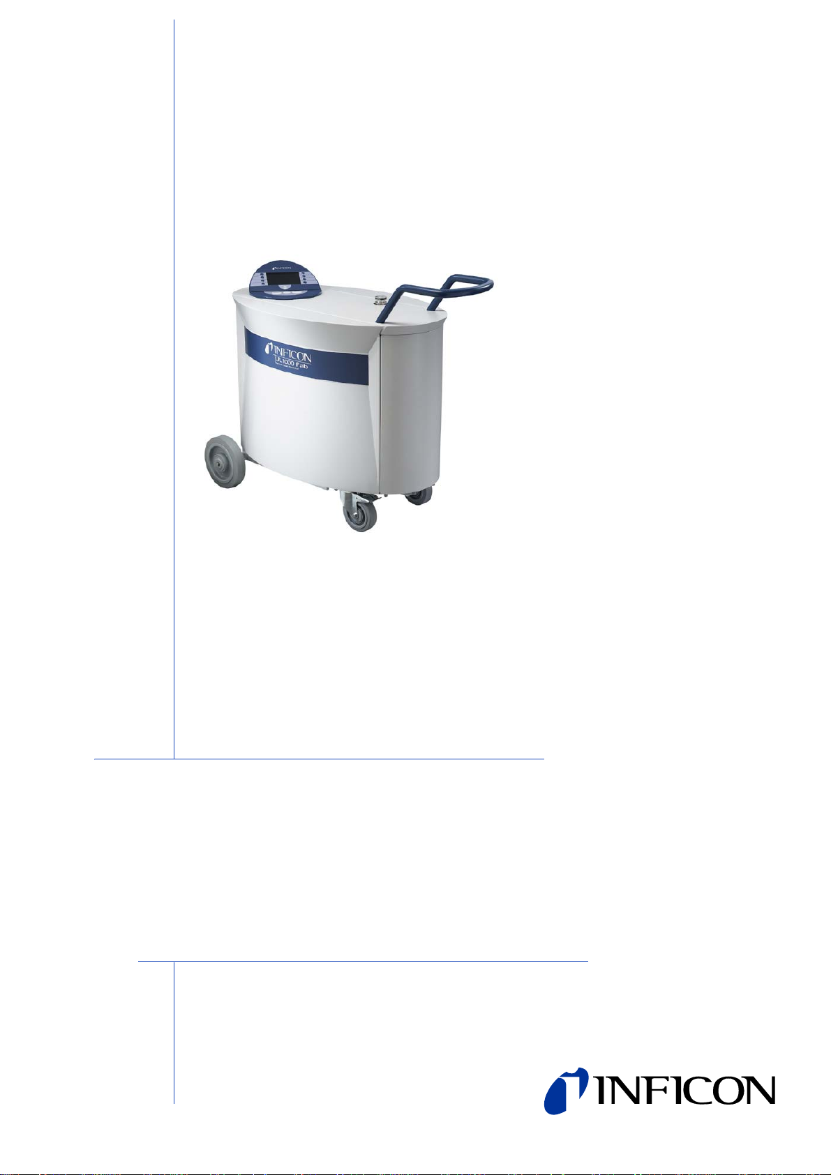
Helium Leak Detector
V5.14
Page 2

iina70e content.fm Technical Handbook(1408)
2
Page 3

Table of Contents
1 General Information 7
1.1 Notes on the Use of this Handbook 7
1.1.1 Safety Symbols 7
1.1.2 Indications 8
1.1.3 Symbols of Vacuum Technology 8
1.1.4 Definiton of Terms 8
1.2 Support from INFICON Service 10
1.2.1 Service Centers 11
1.3 Introduction 13
1.3.1 Purpose 13
1.3.2 Technical Data 15
1.3.2.1 Physical Data 15
1.3.2.2 Electrical Data 15
1.3.2.3 Other Data 16
1.3.2.4 Ambient Conditions 16
1.4 Unpacking 16
1.4.1 Supplied Equipment 17
1.4.2 Accessories and Options 18
1.4.2.1 Sniffer line SL200 18
1.4.2.2 Toolbox 18
1.4.2.3 Helium Bottle Holder 18
1.4.2.4 ESD Mat 18
1.4.2.5 RC1000 Remote control 19
1.4.2.6 Test chamber TC1000 20
2 Installation 21
2.1 Transportation 21
2.2 Working Location 23
2.3 Electrical Connections 25
2.3.1 Mains Power 25
2.3.2 Connections for the Data Acquisition Systems 27
2.3.2.1 Accessories 28
2.3.2.2 Digital Out 28
2.3.2.3 Digital In 29
2.3.2.4 Recorder 30
2.3.2.5 RS232 31
2.3.2.6 Remote Control 31
2.4 Vaccum Connections 32
2.4.1 Inlet Port 32
2.4.2 Exhaust 32
2.4.3 Vent 32
2.4.4 Purge-connection (UL1000 Fab) /
Gas ballast (UL1000) 32
2.5 Default parameters 33
iina70e content.fm Technical Handbook(1408)
Table of Contents 3
Page 4

3 First Operation Check 34
3.1 Needed Equipment 34
3.2 Description of the Initial Operation 34
3.2.1 Start up and Measure 34
3.2.2 Internal Calibration 37
3.2.3 Verification 37
4 Description and Working Principle 38
4.1 Introduction 38
4.2 Components of the UL1000 and UL1000 Fab 38
4.2.1 Vacuum System 39
4.2.2 Control Panel 40
4.2.2.1 LC Display 41
4.2.2.2 START Button 41
4.2.2.3 STOP Button 41
4.2.2.4 ZERO Button 41
4.2.2.5 MENU Button 43
4.2.2.6 Soft Keys 43
4.2.2.7 Numerical Entries 43
4.3 Working Modes 45
4.3.1 Vacuum Mode 45
4.3.2 Sniffer Mode 47
4.3.3 Auto Leak Test Mode 47
5 Operation of the UL1000 and UL1000 Fab 48
5.1 Display 48
5.2 The Screen in Run-Up Mode 48
5.3 Display in stand-by mode 49
5.3.1 Purging 49
5.4 The Screen in Measurement Mode 49
5.4.1 Call for Calibration 49
5.4.2 Speaker Volume 50
5.4.3 Status Line in the Display 50
5.4.4 Numerical Display Mode 51
5.4.5 Trend Mode 51
6 Description of the Menu 52
6.1 Main Menu 52
6.2 View 54
6.2.1 Scale linear/logarithmic 55
6.2.2 Display-range auto/manual 55
6.2.3 Time axis 56
6.2.4 Contrast 56
6.2.5 Background in Stand-by 57
6.2.6 Decimal places 57
6.2.7 Lower display limit 58
6.3 Mode 58
6.3.1 Auto Leak Test 59
iina70e content.fm Technical Handbook(1408)
4 Table of Contents
Page 5

6.4 Trigger & Alarms 61
6.4.1 Trigger Level 1 61
6.4.2 Trigger Level 2 62
6.4.3 Volume 62
6.4.4 Units 63
6.4.5 Alarm delay 63
6.4.6 Audio alarm type 64
6.4.6.1 Pinpoint 64
6.4.6.2 Leak rate prop. 64
6.4.6.3 Setpoint 65
6.4.6.4 Trigger alarm 65
6.5 Calibration 65
6.6 Settings 66
6.6.1 Vacuum settings 67
6.6.1.1 Automatic purge (UL1000 Fab only) 67
6.6.1.2 Vent delay 67
6.6.1.3 Vacuum ranges 68
6.6.1.4 Leak rate internal test leak 69
6.6.1.5 Machine factor 69
6.6.1.6 Auto Leak Test adjustments 69
6.6.2 Zero & Background 73
6.6.2.1 Background Suppression 73
6.6.2.2 Zero 73
6.6.3 Mass 74
6.6.4 Interfaces 75
6.6.4.1 Control Location 75
6.6.4.2 RS232 Protocol 76
6.6.4.3 Recorder output 77
6.6.4.4 Scaling Recorder Output 78
6.6.5 Miscellaneous 79
6.6.5.1 Time&Date 79
6.6.5.2 Language 79
6.6.5.3 Leak rate filter 80
6.6.5.4 Mains Frequency 80
6.6.5.5 Service interval exhaust filter 80
6.6.5.6 Service message exhaust filter 81
6.6.6 Parameter save / load 81
6.6.6.1 Load parameter set 81
6.6.6.2 Save parameter set 82
6.6.7 Monitoring functions 82
6.7 Information 85
6.7.1 Service 85
6.8 Access Control 86
6.8.1 Access to CAL function 86
6.8.2 Access to Trigger&Alarme menu 87
6.8.3 Change Device PIN 87
6.8.4 Change Menu-PIN 87
7 Calibration 88
iina70e content.fm Technical Handbook(1408)
7.1 Introduction 88
Table of Contents 5
Page 6

7.2 The calibration routines 88
7.2.1 Internal Calibration 89
7.2.1.1 Automatic Internal Calibration 89
7.2.1.2 Manual Internal Calibration 89
7.2.2 External Calibration 89
7.3 Factor of Calibration - Range of Values 93
8 Error And Warning Messages 94
8.1 Hints 94
8.2 List of Errors & Warnings 95
9 Maintenance Work 99
9.1 General Information 99
9.2 Maintenance or Service at INFICON 100
9.3 Key to the Maintenance Plan 100
9.4 Maintenance Plan 101
9.5 Maintenance Groups 102
9.5.1 1500 Hours Maintenance 102
9.5.2 4000 Hours Maintenance 102
9.5.3 8000 Hours Maintenance 103
9.5.4 16000 Hours Maintenance 103
9.5.5 Notes refering the maintenance of the SplitFlow 80 104
9.6 Description of the Maintenance Work 104
9.6.1 Opening the Instrument for Maintenance Purposes 105
9.7 Checking and Replacing the Filter Insert 106
9.8 Replacing the Exhaust Silencer 108
9.9 Checking/Emptying the Exhaust Filter 109
9.9.1 Replacing the Filter Insert 109
9.10 Monitoring the Oil Level of the D16 B and Topping up the Oil 111
9.11 Oil Change for the D16B 112
9.12 Scroll Pumps (UL1000 and UL1000 Fab only) 114
6 Table of Contents
Appendix 115
A Diagram 115
B Index 116
C Declaration of Conformity 118
iina70e content.fm Technical Handbook(1408)
Page 7
1 General Information
Caution
Warning
STO P
Danger
Skilled personnel
Notice: We recommend that you carefully read this technical handbook to ensure
optimum operating conditions right from the start.
This technical handbook contains important informations on the functions,
installation, start-up and operation of th e UL 10 00 and UL1 0 00 Fa b.
General
We reserve the right to modify the design and the specified data. The illustrations are
not binding.
1.1 Notes on the Use of this Handbook
1.1.1 Safety Symbols
Important remarks concerning operational safety and protection are emphasised as
follows:
Information on correct handling or use. Disregard can lead to malfunctions or minor
equipment damage.
Information on preventing extensive equipment and environmental damage.
Information on preventing any kind of physical injury.
Indicates procedures that must be performed by skilled personnel only.
iina70e 01.fm technical handbook(1408)
General Information 7
Page 8
1.1.2 Indications
Tipp Information on helpful procedures.
Notice: Information on special technical requirements that the user must comply
with.
The references to diagrams consists of the chapter number, figure number and the
item number in this order. F or example : Fig. 2-4/ 7 refers to item 7 in t he figure 4 of
chapter 2.
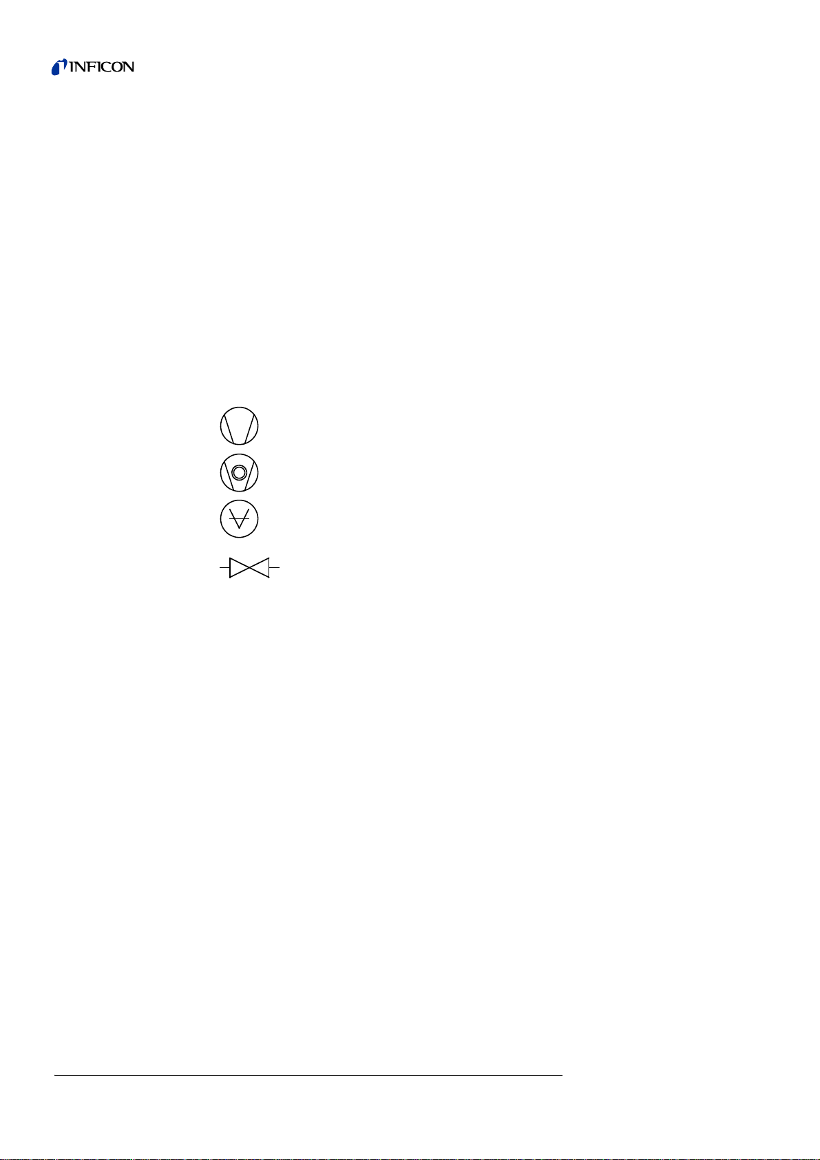
1.1.3 Symbols of Vacuum Technology
Given in the following are some important vacuum symbols which are used in this
manual.
Vacuum pump in general
Turbomolecular pump
Measuring instrument
1.1.4 Definiton of Terms
Autoranging
The range of the preamplifier and the vacuum ranges are selected automatically.
The autoranging feature of the UL1000 Fab covers the entire range or leak rates
depending on the selected operating mode. Not only the leak rate signal, but also the
pressure in the test sample (inlet pressure P1) and the forevacuum pressure (P2) are
used for control purposes. Range switching between the main ranges is performed
via valves. Fine range switching within the m ain ranges is implemen ted by switching
over the gain factor of the preamplifier.
Autotune
Mass alignment
This function automatically aligns the mass spectrometer so that a maximum leak
rate is displayed. The control processor changes the voltage which erates the ions
in the selected mass range until a maximum ion current is detected by the ion
detector. During each calibration the mass alignment is run automatically.
Valve
8 General Information
iina70e 01.fm technical handbook(1408)
Page 9

Auto zero
Measurement and automatic adaptation to the helium background.
This function determines the internal ZERO level of the unit which is then deducted
from the currently measured leak rate signal. This function is enabled by pressing
the Start key provided the UL1000 or UL1000 Fab have ru n at least 20 s in "Standby"
mode or in "Ventilation" mode.
If the before suppressed helium background further decreases and only the display
limit appears, the ZERO-level will be adjusted automatically
Menu
The menu allows the user to program the UL10 00 and UL 100 0 Fab accordin g to his
requirements. The menu has a tree architecture.
Default
Status of the UL1000 and UL1000 Fab when supplie d by the fa cto ry .
GROSS
GROSS is a measurement mode which allows high inlet pressure (1 to 15 mbar).
The smallest detectable leak rate is 1x10
-6
mbar l/s.
FINE
FINE is the medium measurement mode with inlet pressure between 2 and 0,4mbar.
Detection limit is 1x10
-10
mbar l/s.
ULTRA
ULTRA is the most sensitive measuring range with inlet pressures below 0,4 mbar.
The minimum detectable leak rate is 5x10
-12
mbar l/s.
Foreline pressure
Pressure in the foreline between Turbo pump and scroll pump.
Minimum detectable leak rate
The smallest leak rate the UL1000 and UL1000 Fab is able to detect
( 5x10
-12
mbar l/s).
Internal helium background
The existing helium partial pressure in the measurement system. The level of the
internal helium background is measured in the Stand-by mode and subtracted from
the measured signal.
Measure Measurement mode
The UL1000 and UL1000 Fab measures the leak rate of the test sample.
iina70e 01.fm technical handbook(1408)
General Information 9
Page 10
1.2 Support from INFICON Service
INFICON GmbH
Bonner Str. 498,50968 Cologne, Germany
Tel: +49 221 3474 2222 Fax: +49 221 3474 2221
m
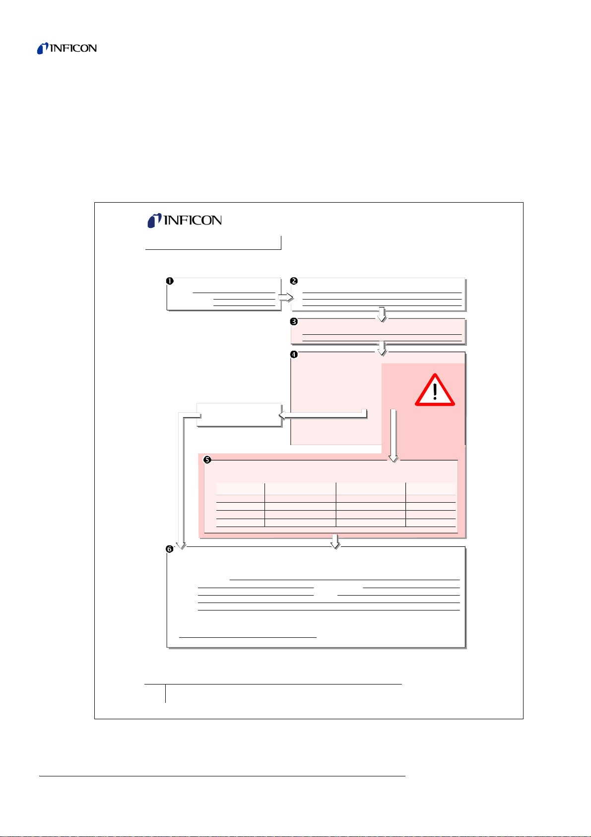
zisa01e1-a
Declaration of Contamination
Legally binding declaration:
I/we hereby declare that the information on this form is complete and accurate and that I/we will assume any further costs that may
arise. The contaminated product will be dispatched in accordance with the applicable regulations.
Organization/company
Address Post code, place
Phone Fax
Email
Name
Date and legally binding signature Company stamp
1) or not containing any amount
of hazardous residues that
exceed the permissible ex posure limits
Process related contamination of product:
toxic no 1) yes
caustic n o 1) yes
biological hazard no
yes 2)
explosive no
yes 2)
radioactive no
yes 2)
other harmful substances no1) yes
The service, repair, and/or disposal of vacuum equipment and components will only be carried out if a correctly completed declaration has
been submitted. Non-completion will result in delay.
This declaration may only be completed (in block letters) and signed by authorized and qualified staff.
Copies:
Original for addressee - 1 copy for accompanying documents - 1 copy for file of sender
Harmful substances, gases and/or by-products
Please list all substances, gases, and by-products which the product may have come into contact with:
Trade/product name
Chemical name
(or symbol)
Precautions associated
with substance
Action if human contact
Description of product
Type
Article Number
Serial Number
Reason for return
Operating fluid(s) used (Must be drained before shipping.)
The product is free of any substances which are damaging to
health yes
This form can be downloaded
from our website.
2) Products thus contam i nated will not be ac cepted without written
evidence of deconta mi nation!
If an instrument is returned to INFICON or an authorised representative of INFICON,
please indicate wether the instrument is free of substances damaging to healths or
wether it is contaminated. If it is contaminated also indicate the nature of the hazard.
INFICON must return any appliances without a Declaration of Contamination to the
sender’s address. A form for stating details as to the type of contamination is
reproduced in Fig. 1-1.
A maintenance and service contract is recommended.
Fig. 1-1: Declaration of Contamination form
www.inficon.com leakdetection.service@inficon.co
iina70e 01.fm technical handbook(1408)
10 General Information
Page 11
1.2.1 Service Centers
In case you urgently need assistance please get in touch with the local INFICON
Service in your country or the service hotline in Cologne, Ge rm a ny:
Algeria jhj@agramkow.dk Finland jhj@agramkow.dk
Agramkow
Sonderborg
Belarus leakdetection.service@inficon.com France Christophe.Zaffanella@oerlikon.com
INFICON GmbH
Cologne
Belgium leakdetection.service@inficon.com Germany leakdetection.service@inficon.com
INFICON GmbH
Cologne
Brazil fernandoz@prestvacuo.com.br Hungary adam.lovics@kon-trade.hu
PV Pest Vácuo Ltda.
Santa de Parnaíba
Bulgaria leakdetection.service@inficon.com India asdash@hotmail.com
INFICON GmbH
Cologne
Canada reachus@vpcinc.ca Ireland reach.unitedkingdom@inficon.com
Vacuum Products Canada Ltd.
Ontario
Central America infoqro@meisa.com Italy davide.giovanetti@inficon.com
MEISA S.a. de C.V.
Querètaro
China reach.china@inficon.com Israel urimark@mark-tec.co.il
INFICON LTD
Hong Kong
INFICON LTD
Beijing
INFICON LTD
Guangzhou
INFICON LTD
Shanghai
Czech Republic filip.lisec@inficon.com Korea reach.korea@inficon.com
INFICON GmbH
Pilsen
Denmark jhj@agramkow.dk INFICON Ltd.
Agramkow
Sonderborg
Egypt jhj@agramkow.dk Latvia leakdetection.service@inficon.com
Agramkow
Sonderborg
Estonia leakdetection.service@inficon.com Lithuania leakdetection.service@inficon.com
INFICON GmbH
Cologne
iina70e 01.fm technical handbook(1408)
Phone: +45 741 236 36
Fax: +45 744 336 46
Phone: +49 221 56788-112
Fax: +49 221 56788-9112
Phone: +49 221 56788-112
Fax: +49 221 56788-9112
Phone: +55 114 154 4888
Fax: +55 114 154 4888
Phone: +49 221 56788-112
Fax: +49 221 56788-9112
Phone: +905.672.7704
Fax: +905.672.2249
Phone: +52 44 22 25 42 80
Fax: +52 44 22 25 41 57
Phone: +852.2862.8863
Fax: +852.2865.6883
Phone: +86.10.6590.0164
Fax: +86.10.6590.0521
Phone: +86.20.8723.6889
Fax: +86.20.8723.6003
Phone: +86.21.6209.3094
Fax: +86.21.6295.2852
Phone +420 734 331 758
Fax: +420 604 203 037
Phone: +45 744 336 36
Fax: +45 744 336 46
Phone: +45 741 236 36
Fax: +45 744 336 46
Phone: +49 221 56788-112
Fax: +49 221 56788-9112
Agramkow
Sonderborg
OLV France
Orsay
INFICON GmbH
Cologne
Kontrade
Budaörs
Dashpute
400 064
INFICON
Blackburn
INFICON GmbH
Castelnuovo
Mark Technologies Ltd.
Kiriat Ono
Japan reach.japan@inficon.com
INFICON Co. Ltd.
Yokohama
INFICON Ltd.
Sungnam city
Suwon City
INFICON Ltd.
Cheonan City
INFICON GmbH
Cologne
INFICON GmbH
Cologne
Phone: +45 741 236 36
Fax: +45 744 336 46
Phone: +33 476 351 584
Fax: +33 476 351 584
Phone: +49 221 56788-112
Fax: +49 221 56788-9112
Phone: +36 23 50 38 80
Fax: +36 23 50 38 96
Phone: +91 22 888 0324
Fax: +91 22 888 0324
Phone: +44 1254 678 250
Fax: +44 1254 698 577
Phone: +39 045 6 40 25 56
Fax: +39 045 6 40 24 21
Phone: +972 35 34 68 22
Fax: +972 35 34 25 89
Phone: +81.45.471.3396
Fax: +81.45.471.3387
Phone: +82 312 062 890
Fax: +82 312 063 058
Phone: +82 312 062 890
Fax: +82 312 063 058
Phone: +82 312 062 890
Fax: +82 312 063 058
Phone: +49 221 56788-112
Fax: +49 221 56788-9112
Phone: +49 221 56788-112
Fax: +49 221 56788-9112
General Information 11
Page 12

Mexico infoqro@meisa.com Spain richard.cunill@leyboldoptics.com
MEISA S.a. de C.V.
Querètaro
Netherlands leakdetection.service@inficon.com Sweden jhj@agramkow.dk
INFICON GmbH
Cologne
Norway jhj@agramkow.dk Syria leakdetection.service@inficon.com
Agramkow
Sonderborg
Poland kamola@vakpol.com Taiwan Susan.Chang@inficon.com
VAK-POL & GAZ Sp. zo.o
Pulawy
Portugal leakdetection.service@inficon.com Tunisia leakdetection.service@inficon.com
INFICON GmbH
Cologne
Republic of South Africa vacuquip@hotmail.com Turkey jhj@agramkow.dk
Vacuquip
Randburg
Russia leakdetection.service@inficon.com Ukraine leakdetection.service@inficon.com
INFICON GmbH
Cologne
Singapore reach.singapore@inficon.com United Kingdom reach.unitedkingdom@inficon.com
INFICON PTE LTD.
Singapur
Slovakia filip.lisec@inficon.com United Arab Emirates leakdetection.service@inficon.com
INFICON GmbH
Pilsen
Slovenia medivak@siol.net USA service.usa@inficon.com
Medivac
Ljubljani
South America except Brazil infoqro@meisa.com Inficon Inc.
MEISA S.a. de C.V.
Querètaro
Phone: +52 442 225 42 80
Fax: +52 442 225 41 57
Phone: +49 221 56788-112
Fax: +49 221 56788-9112
Phone: +45 741 236 36
Fax: +45 744 336 46
Phone: +48 60 23 15 212
Fax: +48 60 23 15 212
Phone: +49 221 56788-112
Fax: +49 221 56788-9112
Phone: +27 73 15 78 355 Agramkow
Phone: +49 221 56788-112
Fax: +49 221 56788-9112
Phone: +65.890.6250
Fax: +65.890.6266
Phone +420 734 331 758
Fax: +420 604 203 037
Phone: +386 15 63 91 50
Fax: +386 17 22 04 51
Phone: +52 44 22 12 36 15
Fax: +52 44 22 12 19 40
Leybold Optics Ibérica
Barcelona
Agramkow
Sonderborg
INFICON GmbH
Cologne
INFICON Company Limited
Chupei City, HsinChu Hsien
INFICON GmbH
Cologne
Sonderborg
INFICON GmbH
Cologne
INFICON
Blackburn
INFICON GmbH
Cologne
Inficon Inc.
East Syracuse, NY
San Jose, CA
Inficon Inc.
Austin, TX
Phone: +34 93 66 60 778
Fax: +34 93 66 64 612
Phone: +45 741 236 36
Fax: +45 744 336 46
Phone: +49 221 56788-112
Fax: +49 221 56788-9112
Phone: +886.3.5525.828
Fax: +886.3.5525.829
Phone: +49 221 56788-112
Fax: +49 221 56788-9112
Phone: +45 741 236 36
Fax: +45 744 336 46
Phone: +49 221 56788-112
Fax: +49 221 56788-9112
Phone: +44 1254 678 250
Fax: +44 1254 698 577
Phone: +49 221 56788-112
Fax: +49 221 56788-9112
Phone: +1.315.434.1167
Fax: +1.315.434.2551
Phone: +1.408.361.1200
Fax: +1.408.362.1556
Phone: +1.512.448.0488
Fax: +1.512.448.0398
12 General Information
iina70e 01.fm technical handbook(1408)
Page 13
1.3 Introduction
STO P
Danger
Caution
1.3.1 Purpose
The UL1000 and UL1000 Fab are helium leak detectors. These instruments may be
used to detect the location and the size of leaks on objects under test in two different
ways:
• when the test sample has been evacuated first and is sprayed with helium on the
or
• when a helium overpressure is provided in the test sample and the test sample is
Caution: Danger of explosion
Hydrogen forms a highly explosive gas mixture with air.
Great caution is necessary when using hydrogen! No smoking, no naked flames,
avoid sparks.
outside. It is required that a vacuum connection is provided between the UL1000
and UL1000 Fab and the test sample (vacuum mode).
searched from the outside with a sniffer probe which is attached to the inlet port
(sniffer mode).
The UL1000/UL1000 Fab is only allowed to be used as a leak detector. It ma y not
be used as a pump system (especially not for pumping off aggressive or humid
gasses)
For UL1000 use only:
Notice: Pumping condensable gases and steams: When pumping test sample
water vapour that is inside can attain to the fore pump. With the water vapor
that is in the air - especially in humid areas or wh en using humid or wet test
samples - the acceptable compatibility of water vapor or capacity of water
vapor respectively can be exceeded.
The steam in the oil of the pump condenses when the water vapor rises over the
acceptable value. So the attribute of the oil ch anges and danger of corrosion occures
for the pump.
While using the leak detector with condensable gases and steams the oil of the fore
pump has to be controlled regularly. So you can recognize a condensation of water
vapor in the pump. Usually the oil is light and lucent. When water vapor is inside it
gets blear and milky at operating state temperature.
When turning the pump off water vapor condensates and rases the part of water in
the oil.
iina70e 01.fm technical handbook(1408)
General Information 13
Page 14
Warning
The leak detector must not directly be switched off after the process, in which
Caution
Caution
STO P
Danger
condensable gases or steams are pumped, is finished. It must be ru nning (at least
20 minutes) with opend gas ballast valve (see Chapte r 5.3.1) until the oil of the
pump is free from detachted steams.
When not taking care of this instruction there can be a corrosion within the pump.
So damages will occure.
The height of the oil of the pump has to be controlled regularly.
The normal intervalls of changing the oil from the producer have to be taken care
of. See instructions of the rotary vane pump.
Gases that contain halogen melecules (i.e. fluorine, chlorine), i.e. refrigerants and
SF6, should not be pumped by the leak detector in higher contact rations an d over
a longer time period.
The coating layer of the cathodes (at the ion source) can be affected. This could
cause a burn out of the cathodes.
For UL1000 Fab use only:
Condensable gases and steams can attain the inside of the leak detector and
destruct the fore pump.
With the water vapor that is in the air - especially in humid areas or when using
humid or wet test samples - the acceptable compatibility of water vapor or capacity
of water vapor respectively can be exceeded.
Dangerous gases pollute the machine.
So you must not use the machine for detecting toxical, acidity, microbiological,
explosive, radioactive or other noxious matters.
If you plan to detect noxious matters please contact the manufacturer. Rules for
decontamination will be developed then. If the leak detector alreay has been in
contact with dangerous gases please fill the declaration of contamination, too, and
send it to INFICON before you send the parts.
iina70e 01.fm technical handbook(1408)
14 General Information
Page 15

1.3.2 Technical Data
1.3.2.1 Physical Data
Max. inlet pressure 15 mbar
Minimum detectable Helium leak rates
• in vacuum mode (ULTRA) <5×10
limit of detection in sniffer mode <5×10
Maximum displayable helium leak rate in ULTRA 0.1 mbar l/s
Measurement range 12 decades
Time constant of the leak rate signal (blanked off,
63% of the final value)
Pumping speed (Helium) at the inlet
Max. roughing capability 25 m
• in vacuum mode
Detectable masses 2, 3 and 4
Mass spectrometer 180° magnetic sector field
Ion source 2 filaments;
Inlet port DN 25 KF
Run-up time (after starting) 3 min
<1 s
17.6 cfm (50 Hz)
30 m
21.1 cfm (60 Hz)
– GROSS mode 8 l/s
– FINE mode 7 l/s
– ULTRA mode 2.5 l/s
Iridium/Yttria-oxide
-12
mbar l/s
-8
mbar l/s
3
/h (50 Hz)
3
/h (60 Hz)
Hinweis To get down to the minimum detected leak rate range some conditions
must be fulfilled:
• UL1000 and UL1000 Fab has fully warmed up
• Ambient conditions must be stable (temperature, no vibration/accelerations.)
• The part under test has been evacuated long enough (background is no longer
decreasing)
• ZERO must be active
1.3.2.2 Electrical Data
Part no. 550 - 000A, 550 - 100A 230 V 50 Hz
Part no. 550 - 001A, 550 - 101A 115 V 60 Hz
Part no. 550 - 00 2A 100 V 50/60 Hz
Power consumption 1100 VA
Type of protection IP20
Power cords (EU, USA, UK) 3 m
iina70e 01.fm technical handbook(1408)
General Information 15
Page 16

1.3.2.3 Other Data
Valves solenoid
Dimensions (L × W × H) incl. handle in mm 1068 × 525 × 850
Dimensions (L × W × H) incl. handle in inches 42 × 21 × 33
Weight in kg 110
Weight in lbs 242
Noise level dB (A) < 70
Noise level dB (A) 0.5m distance < 56
Audio alarm dB (A) 90
Contamination level (to IEC 60664-1) 2
Overvoltage category (to IEC 60664-1) II
1.3.2.4 Ambient Conditions
For use within buildings
Permissible ambient temperatur e (d ur in g op er at ion) +10 °C … +40 °C
Permissible storage temperature 0 °C … +60 °C
Max. rel. humidity 80% non condensing
Max. permissible height above sea level (during operation) 2000 m
1.4 Unpacking
Unpack the UL1000 and UL1000 Fab immediately after delivery, even if it will be
installed later on.
Examine the shipping container for any external damage. Completely remove the
packaging materials.
Check if the UL1000 and UL1000 Fab is complete (See Chapter 1.4.1) and carefu lly
examine the leak detector visually.
If any damage is discovered, report it immediately to the forwarding agent and
insurer. If the damaged part has to be replaced, please contact the orders
department.
Notice: Before starting up make sure that the transportation fixing is loosened.
(Please refer to chapter 2.1)
Tipp Retain the packaging materials in the event of complaints about damage.
Tipp For unpacking please use the wedge which is part of the packaging.
16 General Information
iina70e 01.fm technical handbook(1408)
Page 17
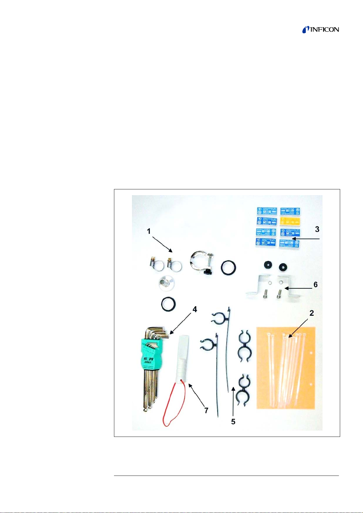
1.4.1 Supplied Equipment
• Helium Leak Detector UL1000 or UL1000 Fab
• Exhaust hose adapter with clamps (see arrow 1)
• power cord fixture
• Set of fuses (see arrow 2)
• Set of tools (see arrow 7)
• Bellow Clips (2 + 2) (see arrow 5)
• Folder with documents
– Technical Handbook UL1000 and UL1000 Fab
– Spare Parts List UL1000 and UL1000 Fab
• hooks to wrap power cord (with screws) (see arrow 6)
• Tool to open the UL1000 and UL1000 Fab (see arrow 7)
• O-Ring with filter (for use at applications with particles)
iina70e 01.fm technical handbook(1408)
Fig. 1-2
General Information 17
Page 18

1.4.2 Accessories and Options
The following parts can be ordered additionally:
• Sniffer Line SL200 14005
• Leak Ware 14090
• Helium Sniffer QUICK-TEST QT100 15594
• Tool Box (detachable) 551-000
• Helium Bottle Holder 551-001
• ESD Mat 551-002
• RC1000 Remote control
• Test chamber TC1000 551-005
• spray gun with hose 16555
• set of plugs 20099024
• LeakWare (software package) 14090
1.4.2.1 Sniffer line SL200
By use of the sniffer line the UL1000 and UL1000 Fab can easily be converted to a
sniffer leak detector. The length of the sniffer line is 4m (i.e. 12 feet).
1.4.2.2 Toolbox
The toolbox is a detachable compartment with a lockable lid. Fittings and small
fixtures can be stored plus the hand set (Please refer to Chapter 1.4.2.5). The
storage volume is approximately 5 l.
The toolbox is placed on the working surface and jammed by the handle.
– RC1000WL wireless version
– RC1000C cable version
– Extension Cable, 8 m
551-015
551-010
14022
1.4.2.3 Helium Bottle Holder
The helium bottle holder allows you to carry a helium reservoir a nd a spray g un with
the UL1000 and UL1000 Fab. Only small and midsize bottles (max 10 l, 200 bar) will
fit without influencing the stability of the UL1000 and UL1000 Fab.
1.4.2.4 ESD Mat
This mat is put on the working surface of the UL1000 and UL1000 Fab and is
clamped and grounded by the inlet port ring. It avoids electrical disch arge s between
the working surface and sensitive test parts.
18 General Information
iina70e 01.fm technical handbook(1408)
Page 19
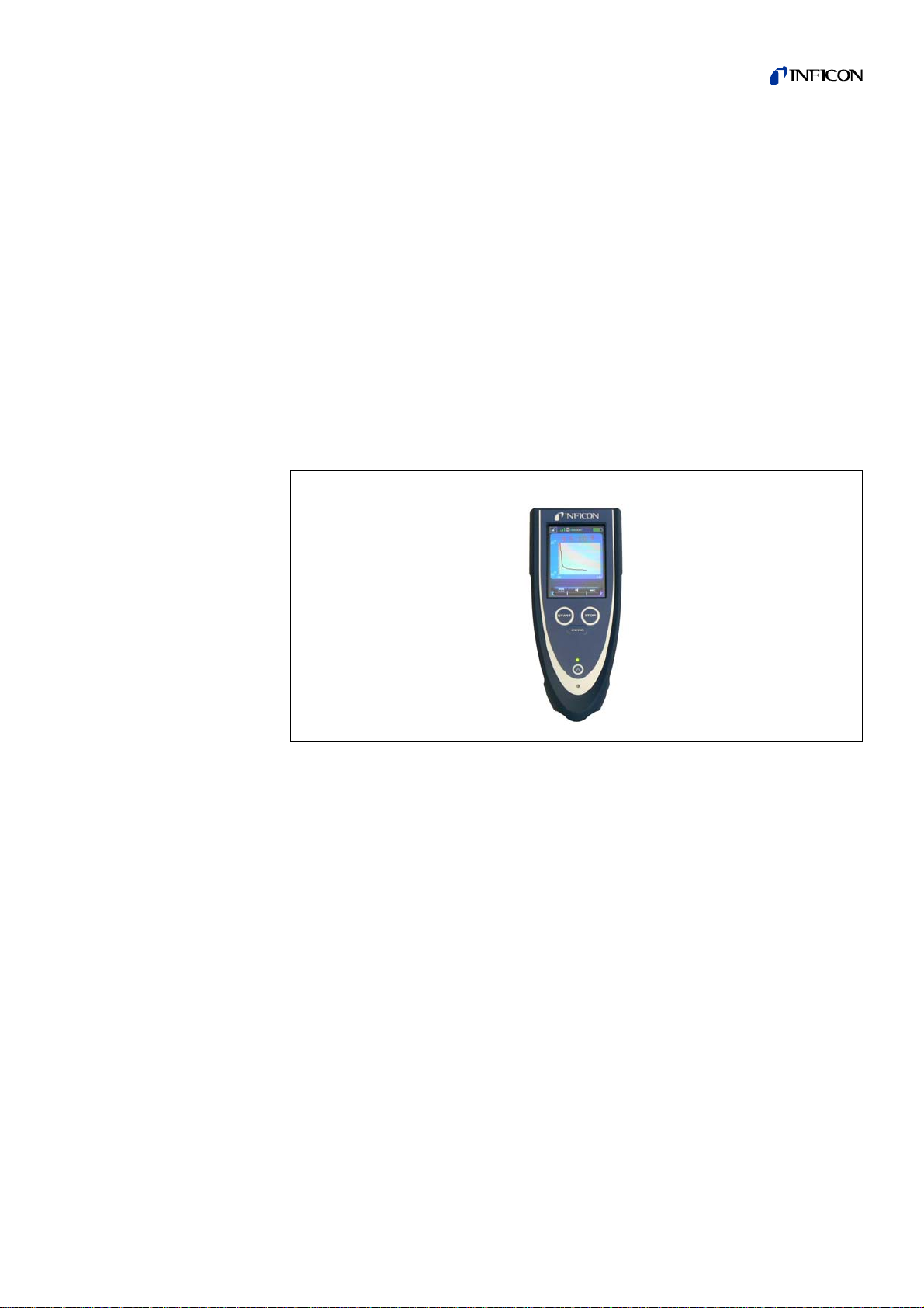
1.4.2.5 RC1000 Remote control
The RC1000 is a wireless remote control that allows to operate the UL1000 and
UL1000 Fab from distance up to 100 m. It provides the functions START, STOP/
VENT, ZERO and speaker volume, and displays leak rate in bargaraph or in chart
mode. (see also Technical Handbook RC1000.)
Measured values can be stored in an internal memory for up to 24 hours of recording
time. The data can easily be downloaded to a USB stick to save it.
An internal trigger can be set to provide a warning if the limit leak rates are exceeded.
An optical warning is shown on the display and an acoustic warning signal is
sounded on the integrated loudspeaker or the connected headphones.
The RC1000 remote control is housed in a robust housing to enable ergonomic
working. Magnets on the underside of the unit enable it to be attached to horizontal
or vertical metal surfaces.
The RC1000 also enables remote operation of the leak test device in question using
a connection cable of up to 28 metres in length.
Fig. 1-3 RC1000 wireless remote control
iina70e 01.fm technical handbook(1408)
General Information 19
Page 20
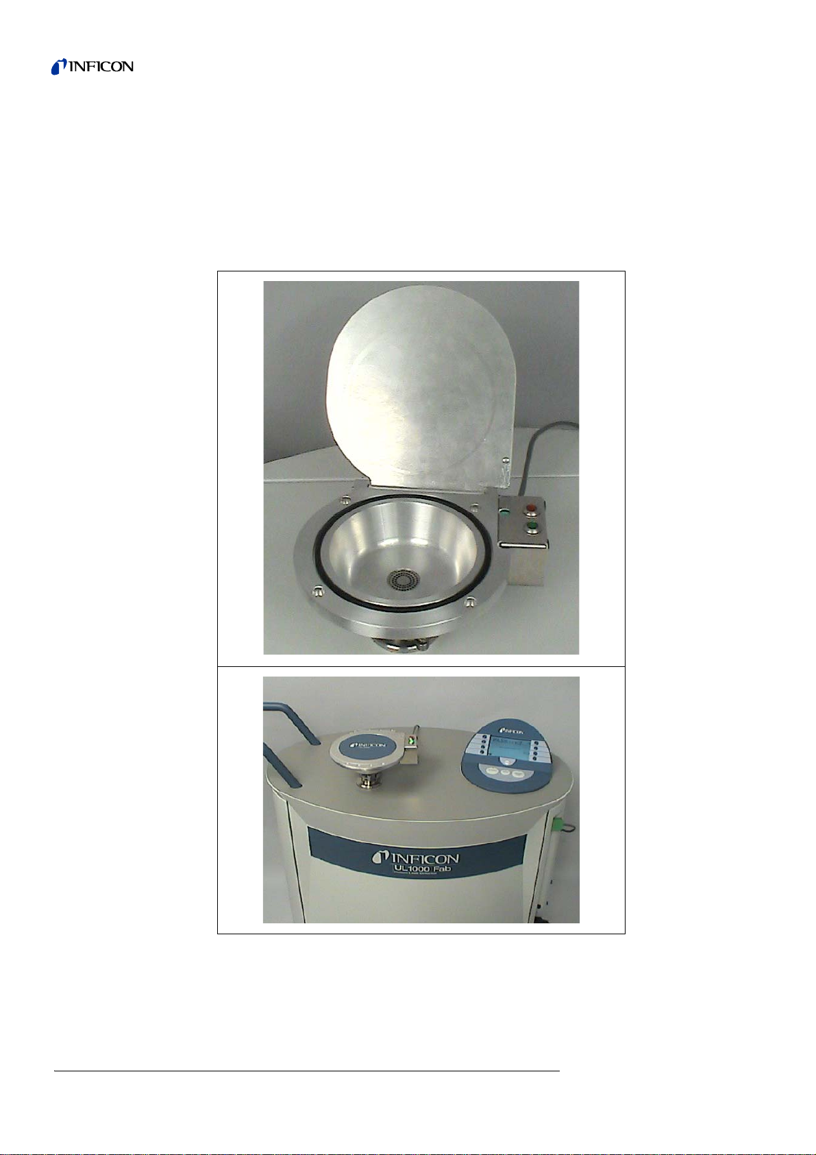
1.4.2.6 Test chamber TC1000
This test chamber turns the UL1000 / UL1000 Fab into a workstation to test
hermetically sealed components.
Testing according to MIL-STD 883 can be done easily, fast and accurate. The test
starts automatically when the chamber lid is closed, test parameters like cycle time
and rejectant level can be setted in the menu Auto Leak Test (see 6.6.1.6). The test
cycle runs automatically, the test result is also displayed by red / green LEDs directly
at the chamber.
Fig. 1-4 Test chamber TC1000
20 General Information
iina70e 01.fm technical handbook(1408)
Page 21
2 Installation
Caution
Warning
Caution
Caution
Caution
2.1 Transportation
The UL1000 and UL1000 Fab is not equipped with any crane eyes and must
therefore not be transported using lifting equipment.
The UL1000 and UL1000 Fab must only be pushed or pulled along using the handle
provided for this purpose. Don’t use the handle to lift.
Your feet can be pinched.
Keep your feet away from the rollers. .
Your feet can be run over.
Do not pull the unit, push it
When transporting over longer distances the original pa ckaging must be used . The
castors must not be fixed when the UL1000 and UL1000 Fab is sh ipped in a crate.
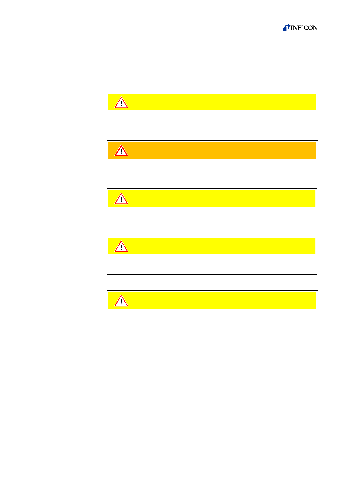
UL1000 Fab with Triscroll TS 620
For transportation the chassis plate where the pump is mounted on has to be
secured by a transportation fixing.
This transportation fixing consists of 2 screws at chassis of the UL1000 Fab (one on
each side).
To get access to these screws remove the side covers of the UL1000 Fab.
There are orange labels on the bottom part pointing to the screws:
iina70e 02.fm technical handbook(1408)
Installation 21
Page 22
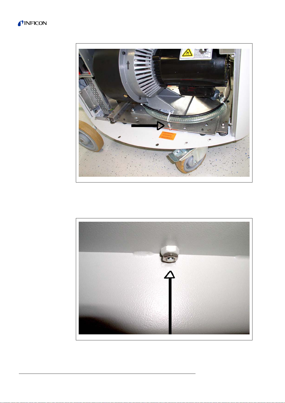
Fig. 2-1
For transportation fixing the screws are tightened to the chassis plate. For oper ation
of the UL1000 Fab the screws should be loosened.
To loosen the screws first loosen the counter nut that is accessible from und erneath:
22 Installation
Fig. 2-2
iina70e 02.fm technical handbook(1408)
Page 23
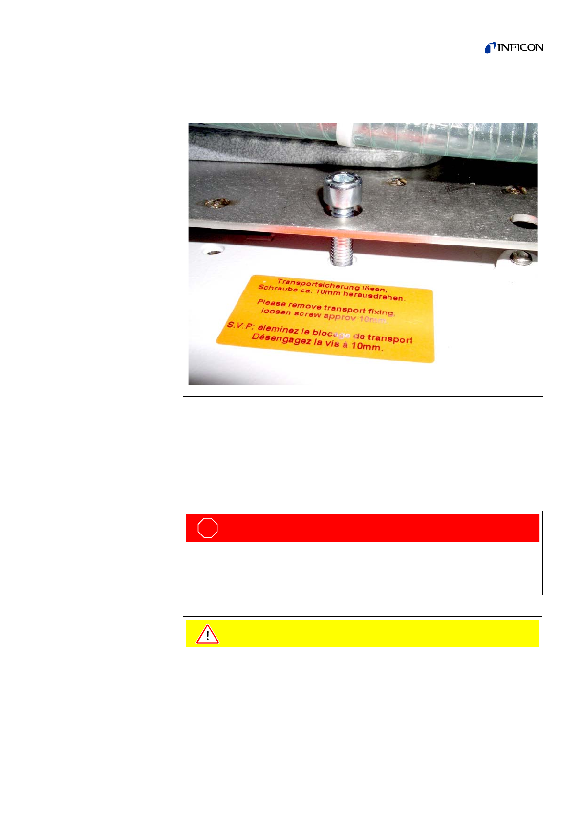
Loosen the screws approximately 10 mm above the chassis plate and tighten then
STO P
Danger
Caution
the counter nuts again:
Fig. 2-3
For transportation tighten the screws again and fix them by the counter nuts.
2.2 Working Location
Move the UL1000 and UL1000 Fab to the desired position and arrest the castors.
Caution: Exhaust gases and fumes:
Exhaust gases and fumes from oil-sealed pumps may be harmful to health.
For operation in poorly ventilated rooms, an exhaust pipe should be connected to
exhaust connection 5 depending on the application and gases used.
Make sure that you can always reach the mains plug.
iina70e 02.fm technical handbook(1408)
Installation 23
Page 24
Warning
The UL1000 and UL1000 Fab must not be operated while standing in water or
Warning
Warning
Caution
Caution
when exposed to drip water. The same applies to all other kinds of liquids.
Avoid contact with bases, acids or solvents as well as exposure to extreme climatic
conditions.
The UL1000 and UL1000 Fab is designed for indoor use only.
Ensure a sufficient air cooling. The air inlet as well the air discharg e openings must
never be obstructed.
The UL1000 and UL1000 Fab can be locked by arresting the castors of the front
wheels to avoid movements on skewness.
It is recommended that you check all major helium sources in the vicinity of the
UL1000 and UL1000 Fab within a radius of about 10 m for the presence of any big
leaks. You may use the sniffer probe for this.
iina70e 02.fm technical handbook(1408)
24 Installation
Page 25
2.3 Electrical Connections
Warning
STO P
Danger
2.3.1 Mains Power
Notice: Generally the local regulations for electrical connections m ust be observed.
Before connecting the UL1000 and UL1000 Fab to the mains you mu st make sure
that the mains voltage rating of the UL1000 and UL1000 Fab coincides with the
locally available mains voltage. The instrument must exclusively be connected to a
single phase supply with fuses for installation (Circuit breaker 16A max. according
to IEC/EN 60898 with tripping characteristic B).
The mains voltage rating for the UL1000 and UL1000 Fab can be read off from the
name plate beneath the mains socket Fig. 2-6/7 at the back side. This vo ltage is fixed
and can not be changed.
A separate fuse for each of the mains conductors has been integ rated into the mains
switch.
The mains voltage is applied to the instrument via the detachable mains ca ble which
is supplied with the instrument. A mains socket Fig. 2-6/7 is available for this purpose
at the back side of the instrument.
Caution: mains voltage:
Improperly grounded or fused products can lead to fatal injuries.
Only 3-core mains cables having a protection ground conductor must be used.
Operation of the UL1000 and UL1000 Fab where the ground conductor has been
left unconnected is not permissible.
Notice: The cable can be secured like shown in the following Figure.
iina70e 02.fm technical handbook(1408)
Installation 25
Page 26
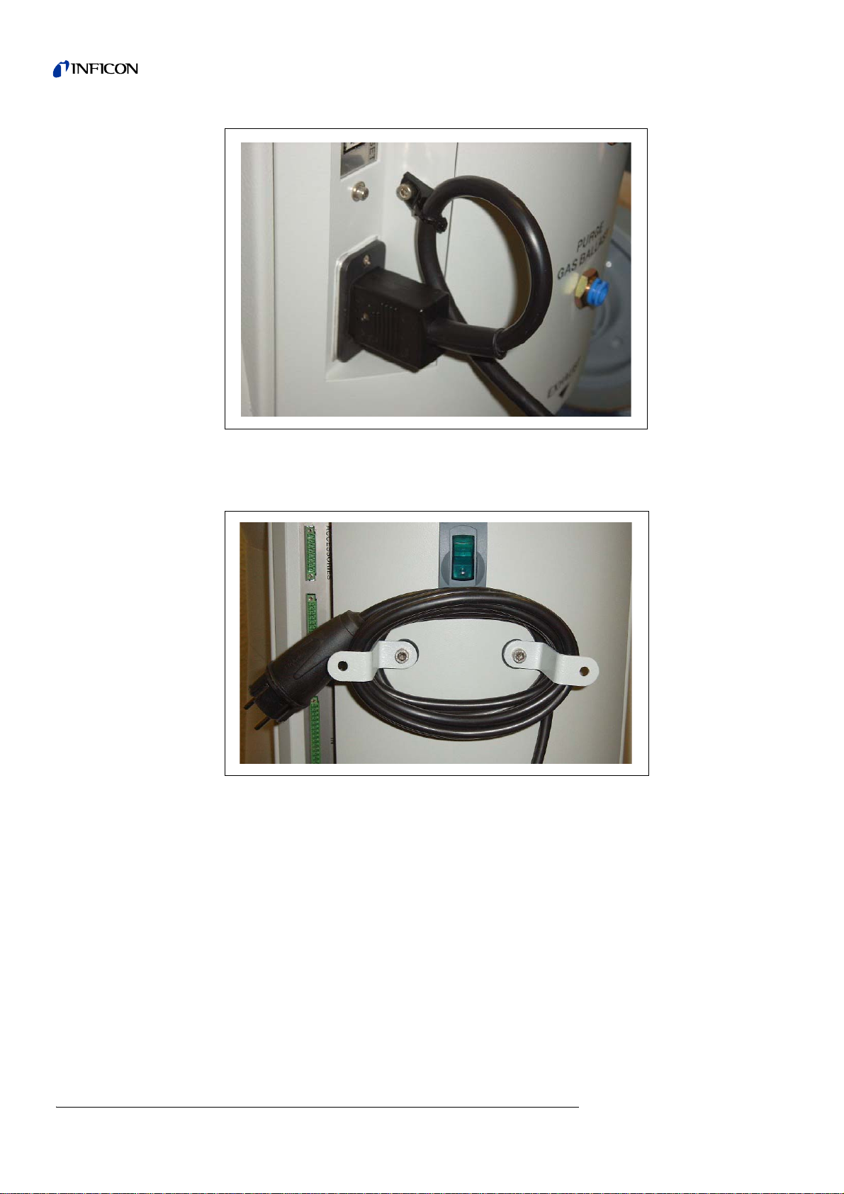
Fig. 2-4 secure fixture power cord
Notice: If the machine is not operating the cable can be stored at the cable holders.
Fig. 2-5 storing power cord
26 Installation
iina70e 02.fm technical handbook(1408)
Page 27
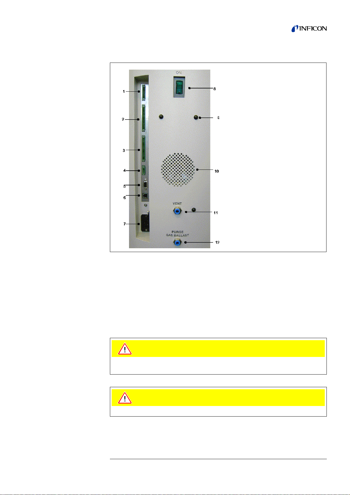
2.3.2 Connections for the Data Acquisition Systems
Caution
Caution
1. Accessories
2. Digital Out
3. Digital In
4. Recorder
5. RS232
6. Remote Control /
Wireless transmitter
7. Mains Socket
8. Mains Switch
9. Hole to mount cable hooks.
10. Speaker
11. Vent
12. Purge (UL1000 Fab) /
Gas ballast (UL1000)
Fig. 2-6
Tipp The sockets: Accessories, Digital Out, Digital In and Recorder have pin 1
on top. The pin numbers are counted downwards. The socket 2 and 3 are
coded mechanically to avoid a confusion with the counter plug. For the
connection with the counter plug (set of plugs 20099024) remove the
plastic pins at the plug, accordingly the plug fits the socket.
Tipp The connections for external devices are safely seperated from the mains
and safe low voltage.
The electronic of the device can be destroyed. So just connect de vices to the le ak
detector that are seperated from the mains.
Just connect devices that don’t excess 25V AC/Amp.
iina70e 02.fm technical handbook(1408)
Installation 27
Page 28

2.3.2.1 Accessories
2.3.2.2 Digital Out
The following accessories may be connected to the sniffer line SL200 (P lease refe r
to Chapter Fig. 2-6/1) or the test chamber TC1000:
Contact pins 1 and 3 are fused with a 0.8 A slow-blow fuse. The amount of power
which can be drawn is limited to 10 W. The contacts are numbered from top to
bottom.
Pin Assignment
1 +24 V, constantly applied, power supply for the sniffer line SL200.
2 GND24
3, 6 Input
4, 5, 7, 8 Output
The following relay outputs are available for further signal processing. The maximum
rating for the relay contacts is 60V AC/1A.
Pin Assignment
1 +24V, bridged with pin 1 of socket „Digital In“
2 GND_24V
3 Trigger 1
4 Trigger 2
5Free
6 Zero active
7 Ready
8 CAL active
9 Cal request
10 Error
11 Warning
12 Purge
13 Measure
14 Recorder Strobe
15 Common dig. out
16 Free
28 Installation
Description of the operation mode of the Digital Out.
Trigger 1:
Is open in case Trigger Level 1 is exceeded or the machine is not in condition of
measuring.
Trigger 2:
Is open in case Trigger Level 2 is exceeded or the machine is not in condition of
measuring.
Zero active:
Is closed in case Zero function is running.
Ready:
Is closed in case machine is ready for measurement (Emission on, no error).
CAL active
Closed when machine is in calibrating routine.
iina70e 02.fm technical handbook(1408)
Page 29

2.3.2.3 Digital In
CAL Request
Is opend in case of calibration request. During external calibration a open output
indicates that the external calibrated leak has to be clos ed .
Error
Open when an error is shown.
Warning
Open when a warning is shown.
Purge
Closed when purge is active.
Measure
Closed in case a machine is in measure mode.
Recorder Strobe
Closed in case recorder output is invalid. Only used when record output is set on
„leak rate“.
These inputs can be used to control the UL1000 and UL1000 Fab with a
programmable logic control (PLC).
Pin Assignment
1 +24V, bridged with pin 1 of socket „Digital Out“
2 GND_24V
3Start
4Stop
5Zero
6CAL
7 Clear
8 Purge
9Free
10 Free
11 Common dig
12 Free
13 Free
14 Free
15 Free
16 Free
Description of operation mode of the Digital In.
Zero:
Change from low to high: activate zero
Change from high to low: deactivate zero
Start:
Change from low to high: activate START
Stop:
Change from low to high: activate STOP
When this inlet is longer high than anounced in chapter 6.6.1.2 then ventilate it
additionaly.
iina70e 02.fm technical handbook(1408)
Installation 29
Page 30

2.3.2.4 Recorder
Purge:
Change from low to high: activate purge
Change from high to low: deactivate purge
Clear:
Change from low to high: confirm error message
CAL:
Change from low to high:
When machine is in stand-by mode: start internal calibration. In case machine is
measurement mode: start external calibration. (Premise: external calibration test
leak has to be open and leak rate signal is stable)
Change from high to low:
External calibration: approve that external test leak is closed and leak rate signal is
stable.
High means: U > 13 V(approximately 7mA)
Low means: U < 7 V
The level of the logic signals must not exceed 35V.
Notice: Signals at these inputs are only accepted if the location of control is set to
„PLC“ or „Local and PLC“. Refer to Chapter 6.6.4.1
The recorder output see Fig. 2-6/4 may be used to log th e leak rate, the inlet pressure
and the forevacuum pressure.
The measured values are provided by way of an analogu e signal in the ran ge of 0 V
… 10 V. The resolution is limited to 10 mV. The instrument which is connected to the
recorder output (e. g. X(t) chart recorder) should have an input resistance of no less
than 2.5 k. The measured values are available through pins 1 and 4. The reference
potential (GND) is available at pins 2 and 3. The contacts are numbered from top to
bottom.
Tipp A diagramm showing pressures and leakrate versus voltage is attach ed in
the appendix.
Notice: The chart recorder outputs are electrically isolated from other plugs. If, in
spite of this, hum interference is apparent it is recommended to operate the
UL1000 and UL1000 Fab and the chart recorder from the same mains
phase. If this is not possible, you must make sure that the frame ground of
both instruments is kept at the same potential.
Pin Assignment
1 Analog 1
2GND
3GND
4 Analog 2
iina70e 02.fm technical handbook(1408)
30 Installation
Page 31

2.3.2.5 RS232
This RS232 C interface Fig. 2-6/5 is wired as data communication equipment (DCE)
and permits the connection of a personal computer (PC) for monitoring and data
logging. The connection is made through a 9 pin sub-D socket. For more information
refer to the Interface Description.
2.3.2.6 Remote Control
This Remote Control interface Fig. 2-6/6 is a serial interface to control the UL1000
and UL1000 Fab by the RC1000. The RC1000 Remote Control can be connected via
the wireless transmitter or via an extension cable with a RJ45 plug. Refer to the
RC1000 Technical Handbook for more information.
Pin Assignment
2RXD
3TXD
5GND
7RTS
8CTS
Pin Assignment
2 +24V (fuse 0.8 A time lag)
30V
4 RXD (intern. RS232)
5 TXD (intern. RS232)
iina70e 02.fm technical handbook(1408)
Installation 31
Page 32

2.4 Vaccum Connections
Warning
Warning
2.4.1 Inlet Port
The inlet port is located on the top of the UL1000 and UL1000 Fab. The size of the
flange is DN 25 KF.
Risk of injury due to sucking connection flange.
If the Vacuum-Mode of the UL1000 is activated, the connection flange may suck
bodily parts around the connection flange. Keep bodily parts off the connection
flange.
A test object or a test chamber has to be connected to the inlet port if the vacuum
mode is chosen (See Chapter 6.3).
The inlet port is also used for the connection of the sniffer line.
2.4.2 Exhaust
The exhaust Fig. 2-6/12 flange is located underneat h the UL1000 and UL 1000 Fab
at the back side. The size of the flange is DN 16 KF.
Depending on the chamber the UL1000 and UL100 0 Fab is attached to and the gas
inside the chamber lethal gases can be spoiled into the air through the exhaust.
When shipped only the exhaust filter body is preassembled. The filter cartridge is
supplied together with the leak detector and can be installed at the exhaust.
Instead of this an exhaust line can be connected to the exhaust by the exhaust
adapter.
2.4.3 Vent
Usually the parts under test are vented with ambient air when the test is finished. If
it is required the parts can be vented with a different gas (i. e. fresh air, dry air,
nitrogen, …) at max. 1050 mbar pressure. In this case a vent hose has to be
connected to the hose coupling Fig. 2-6/10.
2.4.4 Purge-connection (UL1000 Fab) /
Gas ballast (UL1000)
For purge modes it is recommended to use Helium-free gases at atmospheric
pressure. Ambient air can be contaminated with Helium due to
In this case a gas supply line (i. e. nitrogen, fresh air, …) should be connected to the
hose coupling Fig. 2-6/11. The pressure of these gas line must not exceed
1050 mbar.
The connector 11 and 12 in Fig. 2-6 are quick connectors for hose diameters of 8/
6 mm.
spraying or charging .
iina70e 02.fm technical handbook(1408)
32 Installation
Page 33

2.5 Default parameters
The following parameters are set like shown when in the menu of the UL1000 and
UL1000 Fab under Settings Parameters load/save, „load default values“ is
chosen.
Auto-scaling: On
Scaling logarithmic
Display range: 4 decades
Time axis: 32 seconds
LCD invers: OFF
Background in stand by mode: OFF
Automatic calibration request: OFF
Mass: 4 (helium)
Recorder Output: leak rate
Volume: 2
Leak rate unit: mbar l/s
Mode: Vacuum
Trigger level 1: 1E-9 mbar l/s
Trigger level 2: 1E-8 mbar l/s
Leak rate external test leak (Vacuum): 1E-7 mbar l/s
Leak rate external test leak (Sniffer): 1E-5 mbar l/s
Vent delay: 2 seconds
Automatic purge: OFF
Pressure unit: mbar
Minimum volume: 0
Beep: ON
Maximum evacuation time: 30 minutes
Audio Alarm Typ: Trigger Alarm
Maximum inlet pressure when sniffing: 1 mbar
Minimum Inlet pressure when sniffing: 0,1 mbar
Number of decimal place at leak rate displayed: 1
Scroll display: On
Particle protection: Off
Direct access to calibration: On
Contamination protection: Off
Switch off limit for contamination protection: 1E-3 mbar l/s
Control location: Local
Alarm delay: 30 seconds
Leak rate filter: I•Cal
Zero: enabled
iina70e 02.fm technical handbook(1408)
Installation 33
Page 34

3 First Operation Check
Warning
Caution
The steps for an initial operation are described in this chapter. It is explained how to
switch on the UL1000 and UL1000 Fab, how to measure and how to carry out an
internal calibration.
Notice: If anything unexpected happens during the initial operation or the leak
detector acts in a strange way the UL1000 and UL1000 Fab can be
switched off by the mains switch at any time.
3.1 Needed Equipment
The following parts will be needed:
• A blind flange 25 KF (if not preassembled at the inlet port).
• A helium test leak with a DN 25 KF adapter (optional).
3.2 Description of the Initial Operation
Please proceed the following description step by step to start the initial operation.
Refer to Chapter 5 Operation of the UL1000 and UL1000 Fab for a more detailed
description.
3.2.1 Start up and Measure
1 Unpack the UL1000 and UL1000 Fab and in spect it for any externa l damage (Refer
to Chapter 1.4 Unpacking).
2 Connect the instrument to the mains power (Refer to Chapter 2.3.1 Mains Power).
3 Switch on the leak detector by using the mains switch Fig. 2-6/8.
Caution: Abrupt movements.
Abrupt movements can damage the runnin g tur b o pu mp .
Avoid abrupt movement and vibration of the instrument (e.g. running over cables,
door sills) during operation and up to 4 minutes after switching off since the turbo
pump can be damaged.
Don’t switch the UL1000 and UL1000 Fab on when ambient temperature is below
10°C.
34 First Operation Check
iina70e 03.fm technical handbook(1408)
Page 35

After power on a welcoming picture appears on the screen of the control panel Fig.
3-1/1, then status information on the speed of the turbo pu mp, the forelin e pressure,
the emission and the active filament are given.
The start up procedure takes about 3 minutes and the end is indicated by a beep.
The UL1000 and UL1000 Fab is in Stand-by mode now.
Fig. 3-1: Top view of the Standards
Pos. Description Pos. Description
1 Control Panel 2 Inlet Port
4 Check if the inlet port Fig. 3-1/2 is blanked off. If not, please mount a blind flange with
O-Ring on the inlet port.
5 Press the START Button Fig. 3-2/6. The inlet will be evacuated and the measured
leak rate will be displayed a moment later.
This is the measurement mode. If a test part was connected you wo uld start spraying
Helium to identify leaks.
iina70e 03.fm technical handbook(1408)
First Operation Check 35
Page 36

Fig. 3-2: Control Panel
Pos. Description Pos. Description
1 LC Display 8 Soft Key no. 5
2 Soft Key no. 1 9 Soft Key no. 6
3 Soft Key no. 2 10 Soft Key no. 7
4 Soft Key no. 3 11 Soft Key no. 8
5 Soft Key no. 4 12 MENU Button
6 START Button 13 STOP Button
7 Control Panel 14 ZERO Button
6 To correct for any background signal (residual Helium in the part under test) you may
press the ZERO Button Fig. 3-2/14. To undo ZERO please press the ZERO Button
for 2 … 3 seconds.
7 Press the STOP Button Fig. 3-2/13, the Standards will go to Stand-by. If you press
STOP a few seconds the inlet of the Standards will be vented.
8 To finish the startup procedure please proceed with #16. For calibration proceed with
#9.
36 First Operation Check
iina70e 03.fm technical handbook(1408)
Page 37

3.2.2 Internal Calibration
9 Proceed the internal calibration (Please refer to Chapter 7.2.1 Internal Calibration).
For better quantitative measurements please allow the unit to warm up (15 … 20
minutes).
•Press Calibration (Soft Key no. 5 Fig. 3-2/8) to get into the calibration menu.
• Select internal (Soft Key no. 4 Fig. 3-2/5) to choose the internal calibration.
• Select automatic (Soft Key no. 8 Fig. 3-2/11). The automatic procedure of the
internal calibration is started and takes about 30 seconds.
10 Press the STOP Button Fig. 3-2/13 until the message STAND-BY / VENTED appears
on the display. The inlet is vented now.
3.2.3 Verification
To verify the accuracy please proceed through the following steps. A test leak is
required. If a test leak is not available please continue with #16.
11 Remove the blind flange from the inlet port and connect the ope n helium test leak to
the inlet port.
12 Press the START Button Fig. 3-2/6 again. The inlet will be evacuated and the leak
rate of the test leak will be measured and displayed.
13 Press the STOP Button Fig. 3-2/13 to interrupt the measurement. The Stand-by
mode will be displayed.
14 Press the STOP Button Fig. 3-2/13 again until the message STAND-BY vented
appears an the display. The inlet is vented now.
15 Remove the helium test leak from the inlet port and put a blind flange onto the inlet
port again.
16 Switch off the leakdetector by using the mains switch Fig. 2-6/8.
The first operation is finished.
iina70e 03.fm technical handbook(1408)
First Operation Check 37
Page 38

4 Description and Working Principle
4.1 Introduction
The UL1000 and UL1000 Fab basically is a helium leak detector for vacuum
applications, i.e. the part under test is evacuated while the test is performed. The
vacuum is achieved with a pumping system that is part of the UL1000 and UL1000
Fab. In addition the vacuum can be generated by pumps with are set up in parallel
to the leak detector.
Another operating mode of the UL1000 and UL1000 Fab is the Sniff mode which can
only be used when a sniffer line (See Chapter 1.4.2 Accessories and Options) is
hooked up.
4.2 Components of the UL1000 and UL1000 Fab
The UL1000 and UL1000 Fab is a self-contained unit in a metal housing on wheels.
This housing contains the entire vacuum system and the according power supplies.
On top of the unit is the inlet port and the display.
38 Description and Working Principle
iina70e 04.fm technical handbook(1408)
Page 39

4.2.1 Vacuum System
The vacuum diagram below shows the major components inside the UL1000 and
UL1000 Fab:
Fig. 4-1: Vacuum Diagramm UL1000 and UL1000 Fab
Pos. Description
1 MS: Mass Spectrometer, Helium sensor (180° magnetic field mass
spectrometer)
2 Turbomolecular Pump (TMP, provides high vacumm conditions in the MS)
3 V1a … V8: Electromagnetic Valves to control the gas flows
4 Scroll pump (provides the fo reline pressu re for the TMP und pum ps down th e
parts under test)
5Inlet Port
The mass spectrometer is mainly composed of the ion source, the magnetic
separator and the ion collector.
Gas molecules getting into the mass spectrometer are ionized by the ion source.
These positively charged particles are acceler ated into the magnetic fie ld following a
circular path, the radius of which depends on the mass-to-charge ratio of the ions.
Only helium ions can pass this filter and reach the ion collector where the stream of
the ions is measured as a electrical current.
For operation the mass spectrometer requires a vacuum level in the range of
-4
1×10
iina70e 04.fm technical handbook(1408)
in turn is backed up by a scroll pump.
mbar and lower. This pressure is provided by the tu rbomolecular pump which
Description and Working Principle 39
Page 40

Besides maintaining the pressure in the mass spectrometer the pump system is used
to evacuate the test parts. It is made sure that the pressure in the m ass spectrometer
is low enough under all circumstances. The valves V1a, V1b, V2, V4a, V4b control
the gas flows when measuring. Valves V5 (only UL1000), V6, and V8 are used to
vent the system and the Turbo pump. Valve V7 opens and closes the internal test
leak during calibration.
With the pressure in the test part being lower than ambient pressure sprayed he lium
can penetrate into the part in case of a leakage. As soon as the pressure conditions
allow it one of the valves to the TMP opens. Now Helium can penetrate in to the mass
spectrometer contrary to the pumping direction of the TMP.
See Chapter 4.3 Working Modes for details.
4.2.2 Control Panel
The Control Panel Fig. 4-2/7 contains a liquid chrystal display (LC Display), the
START, STOP, ZERO and MENU buttons and also eight Soft Keys for the different
menus and inputs.
The control panel itself is rotable.
Fig. 4-2: Control Panel
Pos. Description Pos. Description
1 LC Display 8 Soft Key no. 5
2 Soft Key no. 1 9 Soft Key no. 6
3 Soft Key no. 2 10 Soft Key no. 7
4 Soft Key no. 3 11 Soft Key no. 8
5 Soft Key no. 4 12 MENU Button
6 START Button 13 STOP Button
7 Control Panel 14 ZERO Button
40 Description and Working Principle
iina70e 04.fm technical handbook(1408)
Page 41

4.2.2.1 LC Display
4.2.2.2 START Button
4.2.2.3 STOP Button
4.2.2.4 ZERO Button
The LC Display Fig. 4-2/1 is the communication interface to the operator. It displays
the leak rates, the status report of the machine, messages, warnings and errors.
Pushing the START Button Fig. 4-2/6 enables the UL1000 and UL1000 Fab to start
the measure procedure. If the START button is pushed again in measurement mo de,
the maximum leak rate indicator („hold“ function) is acitvated. This indicator shows
the maximum leak rate since „START“. By pressing the START-button again the
„hold“ function will be started.
Pushing the STOP Button Fig. 4-2/13 interupts the measure procedur e. If the button
is pressed longer the inlet is vented according to the conditions defined in the menu
Vent delay. Please refer to chapter 6.6.1.2 Vent delay to select the time parameters
of the venting.
Pushing the ZERO Button Fig. 4-2/14 enables the zero mode.
When pressing ZERO the currently measured leak rate is taken as a background
signal and is subtracted from all further measurements. As a result the displayed leak
rate then is
•1×10
•1×10
•1×10
-6
in GROSS
-10
in FINE
-12
in ULTRA
To reverse the ZERO function please keep the button pressed for about 3 seconds.
After pressing ZERO the decreasing background is fitted to the course automatically.
So it is possible to recognize leaks even when the signal is decreasing rapidly.
Please also refer to the pictures below.
iina70e 04.fm technical handbook(1408)
Description and Working Principle 41
Page 42

Fig. 4-3 decreasing background
When the measurement signal declines below the saved underground value the
underground value will automatically be equated with the measurement signal. As
soon as the measurement signal is increasing again the saved decreasing value
remains constant. Increasings of the signal are displayed clearly as a leak.
Fig. 4-4 undo ZERO
When you want to see the measurement signal (includin g underground) please press
the ZERO button about 3 seconds. The saved value will be reset to zero. The
underground signal will not be suppressed anymore.
Notice: The ZERO functions can be selected to a special mode that allows to use
it only when the signal of the falling background becomes stable (see
Chapter 6.6.2.2).
42 Description and Working Principle
iina70e 04.fm technical handbook(1408)
Page 43

4.2.2.5 MENU Button
4.2.2.6 Soft Keys
Special Functions
When pressing the MENU button (Fig. 4-2/12) the selecting menu is shown at the
display. This function is not depending on the operating mode when calibrating.
If the menu is opened during the current session the operator will lead to the last
screen before the menu was left.
Pushing the MENU button again leads back to th e screen of the previous working
mode. The software shows the last screen that was used before.
The function of the eight Soft Keys Fig. 4-2/2 … /5 and /8 … /11 depends on the
current menu. Only key 1 and 8 very often have the functions Back/Cancel (Softkey
no. 1) and OK (Softkey no. 8.).
When inputs are allowed or when settings can be selected in a submenu two of the
Soft Keys always have the same function:
• Soft Keys no. 1 Fig. 4-2/2 is Cancel.
It allows to escape from the submenu without any changes of the present settin gs
and return to the previous menu page.
• Soft Keys no. 8 Fig. 4-2/11 is OK.
The selected settings or edited values will be stored and the previous menu page
will be displayed again.
4.2.2.7 Numerical Entries
If you have opened a menu page where anumber can be changed please proceed
in the following way:
• If you don’t want to change anything, press Soft Key no. 1 Cancel.
• The digit that can be changed is displayed inverted. With the arrows (Soft
• To change a digit to a specific number press the corresponding pair of numbers.
Having reached the last digit all corrections have to be confirmed by OK (Soft Key
no. 8).
Key no. 8) and (Soft Key no. 4) you can choose which digit you need to
change.
A submenu opens and the desired number can be selected. The submenu closes
automatically and the next digit of the total number no w is inve rte d .
iina70e 04.fm technical handbook(1408)
Description and Working Principle 43
Page 44

Example
To change the trigger level 1.0x10
-7
(Soft Key no. 3) Fig. 4-5.
Fig. 4-5: Numerical entry of the Trigger Level 1
In the submenu press 3 (Soft Key no. 4) Fig. 4-6.
mbar l/s to 3x 10⁻⁷mbar l/s please press 2/3
44 Description and Working Principle
iina70e 04.fm technical handbook(1408)
Page 45

4.3 Working Modes
V4a
V4b
p
2
V2
MS
V6
V7
p
1
V1b
V1a
V5
TL
V8
V5
V4a
V4b
p
2
V2
MS
V6
V7
p
1
V1b
V1a
V5
TL
V8
V5
4.3.1 Vacuum Mode
As mentioned (Please refer to Chapter 4.2.1 Vacuum System) the sample has to be
evacuated to allow Helium which is sprayed on the outside to enter through any leaks
due to the pressure difference.
When pressing the START Button Valves V1a and V1b open and the sample is
pumped down by the roughing pump (UL1000) or scroll pump (UL1000 Fab). At the
same time valve V2 is closed to avoid an unacceptable pressure increase in the turbo
pump and the mass spectrometer. With valve V2 being closed the turbomolecular
pump is operated without being backed up by the scroll pump. Since the mass
spectrometer is already under vacuum no further gas is pumped. Th us th e pr essure
p
remains constant or increases only slowly.
2
If the pressure p
process), then the evacuation will be broken (V1a and V1b closed) at p
and V2 will open shortly to restore an appropriate foreline (p
The following diagrams show the gas flow during evacuation and during the modes
GROSS, FINE and ULTRA.
even though increases (e.g because of a very long pumping down
2
<1mbar).
2
>10mbar
2
Fig. 4-6: left: Evacuation (no measurement), right: GROSS Mode
The condition for the evacuation process described is maintained until the inlet
pressure p
has dropped below 15 mbar. Now valve V2 opens. Possibly present
1
helium may now flow upstream against the pumping direction of the turbo molecular
pump into the mass spectrometer where it is detected. This mode is called GROSS,
the detection limit is 1×10
iina70e 04.fm technical handbook(1408)
-6
mbar l/s.
Description and Working Principle 45
Page 46

Since the scroll pump continues to evacuate the test sample the inlet pressure p1 will
V4a
V4b
p
2
V2
MS
V6
V7
p
1
V1b
V1a
V5
TL
V8
V4a
V4b
p
2
V2
MS
V6
V7
p
1
V1b
V1a
V5
TL
V8
continue to drop. Below 2 mbar the UL1000 and UL1000 Fab will switch to FINE
mode, i.e. V4a will open and V1b will close. The gas stream enters the turbo pump
at an intermediate level. The sensitivity of the system now is higher, the detection
limit is 1×10
-10
mbar l/s.
Fig. 4-7: left: FINE Mode, right: ULTRA Mode
Now the lower part of the turbo pump further evacuates the sample and after the
pressure p
has reduced below 0.4 mbar the UL1000 and UL1000 Fab switch es into
1
ULTRA mode, i.e. V1a and V4a close and V4b opens. The entrance into the turbo
pump is on a higher level now. The pumping speed at the inlet port is now 2.5 l/s, the
detection limit is 5×10
-12
mbar l/s.
Tipp A special set up of the UL1000 and UL1000 Fab stopps the autoranging
procedure as described above. With th e mode FINE ONLY (Please refer to
Chapter 6.3 Mode) the unit will stay in FINE Mode Fig. 4-7 (left) regardless
the inlet pressure. The valve V1a is closed.
46 Description and Working Principle
iina70e 04.fm technical handbook(1408)
Page 47

4.3.2 Sniffer Mode
In sniff mode a sniffer line (preferably the INFICON standard sniffer line 14005) is
connected to the inlet port. When pressing the START Button the system starts to
pump air through the sniffer line. Due to the constant gas flow through the sniffer line
the software will range directly into FINE mode and stay there. The inlet pressure will
not drop further down. By measuring the inlet pressure the system software makes
sure that the flow through the sniffer line is at the right level. Otherwise warning
messages are generated. The detection limit in sniff mode is <1×10
INFICON’s sniffersystem QT100 may also be used to sniff. Since the QT100
provides a lower inlet pressure it is recommended to keep the system in vacuum
mode to avoid a wrong generation of pressure warnings. The machine factor has to
be adjusted to value 400.
4.3.3 Auto Leak Test Mode
In this mode the test of hermetically sealed testing objects can be performed
automatically. By use of the optional test chamber TC1000 this test mode starts
automatically when closing the chamber lid. Fast test results within seconds are
achieved by using the internal test leak of the UL1000 or UL1000 Fab for a dynamic
calibration, matched to the required test cycle. Leak rates in the 10-9 mbar l/s rang e
can be detected within 5 seconds.
-7
mbar l/s.
iina70e 04.fm technical handbook(1408)
Description and Working Principle 47
Page 48

5 Operation of the UL1000 and UL1000 Fab
The UL1000 and UL1000 Fab is switched on by pushing the mains switch (Please
refer to Chapter 3.2.1 Start up and Measure). After less than 3 minutes, the start up
is completed; the leak detector is then ready to be used for measurements (Standby
mode).
Please connect the part to be tested to the inlet port and press START. The UL1000
and UL1000 Fab starts to evacuate the part. The evacuation time depends on the
volume of the test part. During evacuation the screen shows the inlet pressure online.
Once the pressure of 15 mbar (11 Torr or 1500 Pa) is reached the unit switches to
measurement mode. The corresponding leak rate is displayed. For further
explanations of the screen please refer to Fig. 5-1.
The displayed leak rate corresponds to the helium background concentration in the
part under test. Since the UL1000 and UL1000 Fab continues to pump down the part
this background leak rate will further reduce. As soon as the leak rate is low enough
in respect to your requirements you may start spraying Helium to search for possible
leaks.
When you are finished please press STOP and hold the button a fe w seconds to vent
the part under test.
5.1 Display
The display is used to either show leak rate signals or program specific set-ups and
get information by means of the software menu (Please refer to Chapter 6
Description of the Menu). In addition messages and maintenance instructions are
displayed on the screen (Please refer to Chapter 8 Error And Warning Messages).
5.2 The Screen in Run-Up Mode
In run-up mode the display shows:
• Speed of the number of revo lu tio ns
• Foreline pressure
• State of emission
• Active filament
• A bar graph which shows the run-up progress
Notice: If the display is too bright or too dark you can cha nge the contrast. Ple ase
see Chapter 6.2.4. During run-up phase the menu button can be pushed
(see Chapter 4.2.2.5) to get to the selection menu.
48 Operation of the UL1000 and UL1000 Fab
iina70e 05.fm technical handbook(1408)
Page 49

5.3 Display in stand-by mode
In stand by mode the states are shown in the lower edge of the display (see Chapter
5.4.3). Furthermore calibration (Please refer to Chapter 7) can also be started in
stand by mode and purging, too (see Chapter 5.3.1)
5.3.1 Purging
Every time when the UL1000 Fab changes into stand by mode it can start purging
automatically after 20 seconds. During this purging the scroll pump is flushed through
purge connection (See Fig. 2-6/11).
When the machine is in stand by mode this operation also can be activated manually
(Key 7). By pressing the key again the purging will be discontinued. By pressing
START the activity will be discontinued, too.
5.4 The Screen in Measurement Mode
In measurement mode the leak rates can be diplayed in two different modes:
• Numerically, combined with a bargrap h Fig. 5- 1
• Trend mode (leak rate versus time) Fig. 5-2
In the lower right corner of the display (next to the Soft Key no. 8) you will find a
symbol that allows to switch between the display modes by pressing Soft Key no. 8.
Please refer to chapters 5.4.4 Numerical Display Mode and 5.4.5 Tren d Mode for
explanations of the different display modes.
Access to calibration (Soft Key no. 5) and access to the speaker volume (Soft Keys
no. 2 and no. 3) is the same in all modes. Also the status icons in the bottom line are
in common in all display modes.
Fig. 5-1: Display, measurement mode
5.4.1 Call for Calibration
In all modes the Soft Key no. 5 is used to get to the calibration routine. Refer to
Chapter 7 Calibration for further information regarding calibration.
iina70e 05.fm technical handbook(1408)
Operation of the UL1000 and UL1000 Fab 49
Page 50

5.4.2 Speaker Volume
STO P
Danger
The hearing can be harmed by the audio alarm.
The accoustic output can exceed a level of 85dB(A).
Do only expose to the audio alarm for a short time or use ear protection.
On the left hand side two loud speaker symbols are shown, combined with the signs
+ and -. By pressing the corresponding softkeys (Soft Keys no. 2 and no. 3) the
volume can be adjusted for convenient loudness. In the bottom line of the display
another loud speaker symbol is shown, combined with a number. This number
indicates the level of the current loudness (ranges from 0 to 15).
Refer to Chapter 6.4.3 Volume for information on loudness, alarms, and sound
tracks.
5.4.3 Status Line in the Display
The status line at the bottom of the display informs about (reading from left to right):
Symbol of display Meaning Explanation
S1 • Trigger 1
S2 • Trigger 2
•• • Detected mass
• Volume level
• Warning triangle
Please refer to Chapter 5.4.2
Speaker Volume.
If the trigger values are exceeded
these signs are inverted. (White on
black background.)
see: Trigger 1
Number of dots indicates the mass
number (4 dots = Helium,
2 dots = Hydr o ge n)
Please refer to Chapter 8.1
VAC • Working mode
ULTRA • Vacuum area
ZERO • ZERO
COR • corrected leak rate
Auto Leak Test • Auto Leak Test
I•ZERO • I•ZERO
STABLE • Signal stable
50 Operation of the UL1000 and UL1000 Fab
VAC or SNIFF indicate which
working mode was selected (Please
refer to Chapter 6.3 Mode).
Depending on the inlet pressure the
UL1000 and UL1000 Fab may be in
GROSS, FINE or ULTRA, which is
indicated here (Chapter 4.3 Working
Modes)
Indicates if ZERO-function is active.
Indicates if the leak rate is displayed
as air equivalent.
Indicates if this mode is active
Indicates if I•ZERO function is active.
Indicates if background signal is
stable (see Chapter 6.6.2.2)
iina70e 05.fm technical handbook(1408)
Page 51

5.4.4 Numerical Display Mode
The display shows the leak rate in big digital figures, see Fig. 5-1. The unit of the leak
rate is shown, too. Underneath the leak rate the inlet pressure is displayed in smaller
digits. The units of leak rate and pressure can be defined in the menu (See Chapter
6.4.4 Units).
Below this the same leak rate is shown graphically as a bar. The scale of this bar, i.e.
the number of decades included in this bar can be defined in the menu (Please refer
to Chapter 6.2.2 Display-range auto/manual). The programmed trigger levels
(Please refer to Chapters 6.4.1 and 6.4.2) are indicated at the bar by short vertical
lines: a straight line for trigger 1 and a dotted line for trigger 2.
In addition the inlet pressure is displayed in smaller figures above the bargraph.
5.4.5 Trend Mode
In trend mode the leak rates are displayed over time Fig. 5-2. In addition the actual
leak rate and inlet pressure also are displayed digitally. The time a xis can be defined
in the menu (Please refer to Chapter 6.2.3 Time axis). The intensity axis (y-axis) is
defined the same way as the bargraph (Please refer to Chapter 6.2.1 Scale linear/
logarithmic ff).
Fig. 5-2: Display, trend mode
iina70e 05.fm technical handbook(1408)
Operation of the UL1000 and UL1000 Fab 51
Page 52

6 Description of the Menu
By pressing the MENU push button Fig. 6-1 the main menu will be displayed
regardless of the current working mode.
Fig. 6-1: The Main Menu
The main menu Fig. 6-1 leads the operator to several submenus described in the
following chapters.
6.1 Main Menu
The main menu shows 7 sub-menus. In these sub-menus groups of technical
features are put together logically. From here the next levels of the menu tree can be
reached.
Tipp All following chapters show the path to get to the described me nu line right
underneath the headline. This path is indicated by a dot (•).
Key No. Name Description
1 Back Return to the previous screen.
Display settings like scaling, contrast, system
2 View
3 Mode
4 Trigger & Alarms
5 Calibration
6 Settings
7 Information
8 Access Control
background.
Please refer to Chapter 6.2.
Selection of different working modes like
Vacuum, Sniff
Please refer to Chapter 6.3.
Settings of units, trigger levels and alarms.
Please refer to Chapter 6.4.
Calibration of the UL1000 and UL1000 Fab.
Please refer to Chapter 6.5.
Settings of internal machine parameters.
Please refer to Chapter 6.6.
Information on the UL1000 and UL1000 Fab
(electrical and vacuum data) and servcie menu.
Please refer to Chapter 6.7.
Access restrictions.
Please refer to Chapter 6.8.
The next page gives an overview of the entire menu architecture Fig. 6-2.
iina70e 06.fm technical handbook(1408)
52 Description of the Menu
Page 53

1. Level 2. Level 3. Level
Scale linear/logarithmic
Display-range auto/manual
Time axis
View (See 6.2)
Mode (See 6.3 ) Sniff/Vacuum / Auto Leak Test
Trigger & Alarms (See 6.4 )
Calibration (See 6.5 )
Main Menu
Settings (See 6.6 )
Information (See 6.7)
Access Control (See 6.8)
Contrast
Background in Stand-by
Decimal places
Lower display limit
Trigger Level 1
Trigger Level 2
Volume
Units
Alarm delay
Audio alarm type
internal
external
Vacuum settings
Zero & Background
Mass
Interfaces
Miscellaneous
Parameter save / load
Monitoring functions
View settings
View internal data
Vacuum diagram
View error list
Calibration history
Calibration factors
Service
Access to CAL function
Change Device PIN
Change Menu-PIN
manual
automatic
Edit leakrate
Start
Automatic purge (UL1000 Fab only)
Vent delay
Vacuum ranges
Leak rate internal test leak
Machine factor
Background Suppression
Zero
Control Location
RS232 Protocol
Scaling Recorder Output
Recorder output
Time&Date
Language
Leak rate filter
Mains Frequency
Service interval exhaust filter
Service message exhaust filter
Load parameter set
Save parameter set
Calibration request
Particle protection
Contamination protection
Pressure limits for vacuum ranges
Pressure limits for sniff mode
Maximum evacuation time
Fig. 6-2: Menu structure overview
iina70e 06.fm technical handbook(1408)
Description of the Menu 53
Page 54

6.2 View
• Main Menu > View
In this menu Fig. 6-3 all features that influence the way data are displayed are put
together.
Fig. 6-3: The View Menu
Key No. Name Description
1 Back Return to the main menu.
2 Scale linear/logarithmic
3 Display-range auto/manual
4 Time axis
5 Contrast
6 Background in Stand-by
7 Decimal places
8 Lower display limit
Settings for bargraph and trend mode.
Please refer to Chapter 6.2.1.
Manual or automatic scaling. Please refer to
Chapter 6.2.2
Time axis in trend. Please refer to Chapter
6.2.3
Display contrast. Please refer to Chapter
6.2.4
Background displayed or not. Please refer to
Chapter 6.2.5
Number of decimal places. Please refer to
Chapter 6.2.6
Choice of electrical filters. Please refer to
Chapter 6.6.2
54 Description of the Menu
iina70e 06.fm technical handbook(1408)
Page 55

6.2.1 Scale linear/logarithmic
• Main Menu > View > Scale linear/logarithmic
These settings apply to the bargraph (= bar underneath the digital figures in the
measurement mode) and Y-axis in the trend mode.
The scale of the bargraph can either be linear o r logarithmic. With the arrows (up and
down) it can be determined how many decades the bargraph covers.
Usually a logarithmic scale is recommended because leak rates may change easily
over several decades.
Softkey 2: Linear
Pressing this key switches the display to a linear scale, starting at zero.
Softkey 3: Arrow down (Number of decades)
Pressing this key reduces the number of displayed decades. Th e mini mum value is
2 decades. Only available if log (softkey 6) was chosen.
Softkey 6: Logarithmic
The scaling will be displayed logarithmically.
Softkey 7: Arrow up (Number of decades)
Increase the number of displayed decades. Maximum value is 9 decades. Only
available if log (softkey 6) was chosen.
6.2.2 Display-range auto/manual
• Main Menu > View > Display-range auto/manual
The upper limit of the displayed leak rate range can b e set manually or automatically.
These settings apply to the bargraph (=bar underneath the digital figures in the
measurement mode and y-axis in the trend mode).
With the upper limit defined here the lower limit is set to a value base d on the number
of decades (See Chapter 6.2.1 Scale linear/logarithmic).
Softkey 2: Manual
The upper limit of the displayed range can be set manually.
Softkey 3: Arrow down
.Decrease the upper limit if manual is chosen. The minimum value is 10
Softkey 6: Automatic
The limit of the displayed range will be chosen automatically.
Softkey 7: Arrow up
Increase the upper limit if manual is chosen. The maximum value is 10
Softkey 8:
Save the settings and return to the previous menu.
-11
mbar l/s.
+3
mbar l/s.
If linear scale is selected, the lower limit is always zero. The upper limit is only a
iina70e 06.fm technical handbook(1408)
default value. You can change this on the measure ment screen with the
Soft Key 6
and 7 if you have chosen manual display ranging.
Description of the Menu 55
Page 56

6.2.3 Time axis
6.2.4 Contrast
• Main Menu > View > Time axis
The length of the time axis in trend mode can be changed in steps of 16 … 960 s.
Softkey 3: Arrow down
Decrease the length of the time axis. The minimum time value is 16 seconds.
The time slice is extended during the measurement mode. (Up to max. 960 s) It is
displayed automatically during the AUTO mode.
Softkey 5: ?
Help
Softkey 7: Arrow up
Increase the length of the time axis. The maximum adjustable value is 960 seconds.
• Main Menu > View > Contrast
The contrast of the display can be change d. The changes are applied synchronously.
The recommended value under regular conditions is 50 (or close to it).
Tipp If by accident the display has been set too bright or too dark so that it can
not be read off, this may be changed as follows:
Switch off the UL1000 and UL1000 Fab and turn it on again. During the runup phase press the key no. 3 or 7 so long until the display can be read
properly again. This setting is saved to the EPROM only after confirming
this through the contrast menu. If this setting is not confirmed, the former
setting will be appled after switching on the instrument on again.
Softkey 3: Arrow down
Fade the contrast to dark. The minimum value s is 0.
Softkey 4: Invert display
Invert the contrast of the screen.
Softkey 5: ?
Help
Softkey 7: Arrow up
Fade the contrast to light. The maximum value is 99.
56 Description of the Menu
iina70e 06.fm technical handbook(1408)
Page 57

6.2.5 Background in Stand-by
• Main Menu > View > Background in Stand-by
The internal background leak rate can be displayed in Stand-by mode (ON) or not
(OFF).The default setting is OFF.
Softkey 3: Off
The background leak rate will not be shown.
Softkey 5: ?
Help
Softkey 7: ON
The background leak rate will be shown.
The internal background is generated by residual gas (e. g. helium) tha t has not been
pumped away yet. Sources for residual
surfaces of the leak detector. This internal background will never disappear totally.
Very clean systems which have been pumped for a long time will show a background
in the 10
10
When pressing START the current internal background is subtracted from all further
measured signals automatically. Thus it is made sure that only the net leak rate from
the part under test is measured.
When switched to Stand-by / Vent again a new internal background is calculated
after 25 s. The updated value is underlined. This means that if you press START
when the value is underlined, the actual background signal will be subtracted. If you
press START when the value is not underlined, the old background signal from the
last Stand-by will be subtracted.
-11
-10
mbar l/s range. Under nor mal conditions the backgrou nd level is in the
mbar l/s or low 10-9mbar l/s range.
gas are air or absorbed gases from the inner
6.2.6 Decimal places
• Main Menu > View > Decimal places
The number of the decimal places of the displayed leak rate can be choosen. The
default setting is 1.
Softkey 3: 1
The leak rate will be displayed with one decimal place.
Softkey 7: 2
The leak rate will be displayed with two decimal places.
Two decimals are especially usefull, when the I•CAL leak rate filter (
Chapter
iina70e 06.fm technical handbook(1408)
6.6.5.3) is used.
Please refer to
Description of the Menu 57
Page 58

6.2.7 Lower display limit
• Main Menu > View > Lower display limit
This parameter defines the lower leak rate limit in the measurement ranges.This is
valid for vacuum modes only.
Softkey 3, 7:
Changing of the lower detection limit between 1×10
Softkey 5: ?
Help
6.3 Mode
• Main Menu > Mode
The mode menu Fig. 6-4 enables the submenu to select the different working modes.
-5
and 1×10
-12
Fig. 6-4: The Mode Menu
Key No. Name Description
1 Cancel
3Sniff
4 Not used in this menu.
5 Auto Leak Test See Chapter 4.3.3.
7 Vacuum The normal vacuum mode is in use
8OK
Return to the main menu without any changes
of the present settings.
The normal vacuum mode will be used. See
Chapter 4.3.2, sniffer mode.
Save the settings and return to the previous
menu.
iina70e 06.fm technical handbook(1408)
58 Description of the Menu
Page 59

6.3.1 Auto Leak Test
• Menu > Mode > Auto leak test
After selecting the Auto leak test mode this message pops up:
Fig. 6-5
By pressing OK button the settings menu is called (see 6.6.1.6 )
Notice: If the UL1000 requests a calibration due to the mode change a calibration
message will come up.
Fig. 6-6
iina70e 06.fm technical handbook(1408)
Description of the Menu 59
Page 60

After the settings the display screen shows in STAND-BY this picture:
Fig. 6-7
1 Test result 4 Background
2 Measured leak rate 5 Mode
3 No. of tested parts 6 Standby
Test of parts
The test can be started by START button. When using the test chamber TC1000, the
test starts automatically when closing the chamber lid. After the setted cycle time is
expired or the measured leak rate has gone belo w the trigger level the test stops and
the chamber will be vented. The test can be stopped any time by STOP button.
After starting, the test procedure runs according to the setted measurement period:
Fig. 6-8
1 Remaining measurement time
Shut down
When the test chamber should remain under vacuum after switching off the UL1000
or UL1000 Fab, push the button (cup of coffee), follow the instruction on the display
and switch off the leak detector.
This function can also be used when a test of p arts should be interrupted due to a
brake. You can start the measurement cycle again by pushing the button RESTART.
iina70e 06.fm technical handbook(1408)
60 Description of the Menu
Page 61

6.4 Trigger & Alarms
• Main Menu > Trigger & Alarms
The trigger levels, the volume of the loudspeaker and the units of leak rates and
pressures can be set in this menu Fig. 6-9.
Fig. 6-9: The Trigger & Alarms Menu
Key No. Name Description
1 Back Return to the main menu.
2 Trigger Level 1 Definition of Trigger level 1. See chapter 6.4.1
3 Trigger Level 2 Definition of Trigger level 2. See chapter 6.4.2
4 Volume See chapter 6.4.3
5 Units
6 Not used in this menu.
7 Alarm delay See chapter 6.4.5
8 Audio alarm type Choice of different alarm types. See chapter 6.4.6
Selection of leak rate and pressure units.
See chapter 6.4.4
6.4.1 Trigger Level 1
• Main Menu > Trigger & Alarms > Trigger Level 1
The value of the first trigger level can be set. See Chapter 4.2.2.7 Numerical Entries
for the description of the entry.
Trigger 1 and Trigger 2 are programmable switching thresholds. When these
thresholds will be exceeded the UL1000 and UL1000 Fab reacts as follows:
Display
In the status line of the display the signs for Trigger 1 and Trigger 2 are displayed
inverted if the leak rate exceeds (becomes higher than) the programmed value.
Relay Output
The trigger-relais of the digital out switches. Please refer to Chapter 2.3.2.2, Digital
out, for further details.
Alarm/Loudspeaker
iina70e 06.fm technical handbook(1408)
Additionally Trigger level 1 defines at which level the various alarm types react (See
Chapter 6.4.6, Audio alarm type)
Description of the Menu 61
Page 62

6.4.2 Trigger Level 2
• Main Menu > Trigger & Alarms > Trigger Level 2
The value of the second trigger level can be set. Please refer to Chapter 4.2.2.7
Numerical Entries for the description of the entry.
If Trigger 2 is exceeded the corresponding relay will switch. This is also indicated at
the display (see above).
6.4.3 Volume
• Main Menu > Trigger & Alarms > Volume
The minimum loudness and the regular volume of the loudspea ker can be adjusted .
The minimum loudness is the minimum speaker volume that cannot be exceeded to
even lower values. Thus it is avoided that the actual volume is accidentally adjusted
to a value that is below the noise level of the environment.
The actual volume can be adjusted between 15 (maximum) and the value defined as
minimum loudness.
Softkey 2: Arrow down
Decrease the minimum loudness. The minimum value is 0.
Softkey 3: Arrow down
Decrease the actual volume. The minimum value is limited by the minimum volume.
Softkey 4: Beep off / Beep on
Softkey 5: ?
Help
Softkey 6: Arrow up
Increase the minimum volume. The maximum value is 15.
Softkey 7: Arrow up
Increase the regular volume. The maximum value is 15.
62 Description of the Menu
iina70e 06.fm technical handbook(1408)
Page 63

6.4.4 Units
6.4.5 Alarm delay
• Main Menu > Trigger & Alarms > Units
The prefered leak rate unit can be selected. There is the choice of 4 (m bar, Pa, Torr,
atm)pressure units and 5 leak rate units (mbar l/s, Pa m
3
/s-1, Torr l/s, atm cc/s).
Notice: In Sniff mode the following measuring units are electable (Refer to chapter
6.3): ppm, g/a eq (helium leak rate is equivalent with leak rate R134a), oz/
gr eq (helium leak rate is equivalent with leak rate R134a).
Softkey 2: Arrow up
Scroll up to select a pressure unit.
Softkey 3: Arrow down
Scroll down to select a pressure unit.
Softkey 6: Arrow up
Scroll up to select a leak rate unit.
Softkey 7: Arrow down
Scroll down to select a leak rate unit.
• Main Menu > Trigger & Alarms > Alarm delay
In some applications (for instance during p ump down in a „chambe r test syste m“) it
might be necessary to block an alarm for some time after pressing START.
This delay time of the alarm can be changed.
Softkey 3: Arrow down
Decrease the delay time. The minimum value is 0 seconds.
Softkey 7: Arrow up
Increase the delay time. The maximum value is 10 minutes up to infinity.
After pressing START the loudspeaker is activated as soon as the leak rate drops
below trigger level 1 or after the entered alarm delay time has elapsed. This setting
is only active for the audio alarm types SETPOINT and TRIGGER ALARM (See
Chapter 6.4.6).
iina70e 06.fm technical handbook(1408)
Description of the Menu 63
Page 64

6.4.6 Audio alarm type
f
LRTr. 10.1 • Tr. 1 10 • TR. 1
2570 Hz -
491 Hz -
• Main Menu > Trigger & Alarms > Audio alarm type
The trigger of the audio alarm can be switched on or off.
Softkey 2: Pinpoint
Use this function to localize a leak with a well-known size. Please refer to Chapter 6.4.6.1
Softkey 3: Leak rate prop.
The sound will be proportional to the leak rate signal.
Softkey 5: ?
Help
Softkey 6: Setpoint
Please refer to Chapter 6.4.6.3
Softkey 7: Trigger alarm
An alarm sounds when the trigger 1 is exceeded.
6.4.6.1 Pinpoint
The tone of the acustical signal changes its frequency only in a LR- window Fi g. 6-10
which ranges from one decade below the Trigger level 1 up to one decad e above the
Trigger level 1. Below the window the tone is constantly
constantly high.
Example: The Trigger level 1 is 4×10
changes reaches from 4×10
Please refer to Chapter 6.4.6.2
Please refer to Chapter 6.4.6.4
-7
-8
mbar l/s up to 4×10⁻⁶mbar l/s.
mbar l/s. So the window where the tone
low, above the window it is
Fig. 6-10: Pinpoint
6.4.6.2 Leak rate prop.
The frequency of the accoustic output is proportional to the reading on the bargraph
display. The frequency ranges from 300 Hz to 330 Hz. Please
Scale linear/logarithmic for the definition of the number of decades.
64 Description of the Menu
refer to Chapter 6.2.1
iina70e 06.fm technical handbook(1408)
Page 65

6.4.6.3 Setpoint
f
LRTr. 1
no tone
375 Hz -
1000 • TR.1
3000 Hz -
6.4.6.4 Trigger alarm
The tone is off as long as the leak rate is below the Trigger level 1. Above Trigger 1
the tone varies proportional to the leak rate Fig. 6-11.
Fig. 6-11: Setpoint
As soon as the leak rate increases above trigger level 1, a multi-tone signal is
generated. The tone does not vary with the leak rate.
6.5 Calibration
• Main Menu > Calibration
Please refer to Chapter 7 Calibration for a detailed description of the calib ration.
Fig. 6-12: The Calibration Menu
iina70e 06.fm technical handbook(1408)
Description of the Menu 65
Page 66

6.6 Settings
• Main Menu > Settings
This menu Fig. 6-13 allows to observe and to change the settings of the internal
machine controls.
Fig. 6-13: The Settings Menu
Key No. Name Description
1 Back Return to the main menu.
2 Vacuum settings
3 Zero & Background See Chap ter 6.6.2
4 Mass
5 Interfaces
6 Miscellaneous
7 Parameter save / load See Chapter 6.6.6
8 Monitoring functions
Settings of vacuum system related functions. See
chapter 6.6.1
Switching between helium and hydrogen. See
Chapter 6.6.3
Define the recorder output (analog output) and
choose the control location (local, RS232, PLC).
See Chapter 6.6.4
Change rarely necessary settings (Date,
language). See Chapter 6.6.5
Choose functions of protection of the UL1000 and
UL1000 Fab. See Chapter 6.6.7
66 Description of the Menu
iina70e 06.fm technical handbook(1408)
Page 67

6.6.1 Vacuum settings
• Main Menu > Settings > Vacuum settings
This menu allows to observe and to change the settings belonging to the vacuum
system.
Softkey 2: Automatic purge (UL1000 Fab only)
Refer to chapter 6.6.1.1
Softkey 3: Vent delay
Refer to chapter 6.6.1.2
Softkey 4: Vacuum ranges
Refer to chapter 6.6.1.3
Softkey 5: Auto Leak Test adjustments
Refer to chapter 6.6.1.6
Softkey 6: Leak rate internal test leak
Refer to chapter 6.6.1.4
Softkey 7: Machine factor
Refer to chapter 6.6.1.5
6.6.1.1 Automatic purge (UL1000 Fab only)
• Main Menu > Settings > Vacuum settings > Automatic purge (UL1000 Fab only)
Through this menu it is possible to program the automatic purge (
Chapter
5.3.1) for 20 seconds when switching from measuring to standby mode.
Softkey 3: OFF
Automatic purge is switched off at standby mode.
Softkey 7: ON
Automatic purge is activated. When switching from measurement to STAND-BY the
forepump is rinsed automatically for 20 seconds.
6.6.1.2 Vent delay
• Main Menu > Settings > Vacuum settings > Vent delay
Through this menu item it is possible to define the delay time until the inlet port is
vented when operating the STOP button. When the STOP button is pressed for a
period of time which is shorter than the delay time specified here, the UL1000 and
UL1000 Fab will just change to Stand-by mode.
When the STOP button is pressed for a period of time which is longer than the delay
time specified here, the UL1000 and UL1000 Fab will vent the inlet port.
Please refer to
iina70e 06.fm technical handbook(1408)
Description of the Menu 67
Page 68

6.6.1.3 Vacuum ranges
• Main Menu > Settings > Vacuum settings > Vacuum ranges
With this menu you can adjust different modes concerning the activity of leak
detection. This setting is only active in mode vacuum (see Chapter 6.3).
Softkey 2: Immediately
The inlet port will be vented immediately after pressing the STOP button.
Softkey 3: After 1 second
The inlet port will be vented with a time delay of 1 second.
Softkey 4: After 1.5 seconds
The inlet port will be vented with a time delay of 1.5 seconds.
Softkey 5: ?
Help
Softkey 6: after 2 seconds
The inlet port will be vented with a time delay of 2 seconds.
Softkey 7: No vent
The inlet port cannot be vented with the STOP button.
Softkey No. 2: ULTRA ONLY
In this mode the UL1000 and UL1000 Fab remains in the area ULTRA after ru nning
under 0,4 mbar at the inlet flange (see Chapter 4.3.1). When showing the pressure
at the inlet flange > 0,4 mbar the UL1000 and UL1000 Fab switches immediately into
evacuation mode.
Softkey No. 3: FINE only
In this mode the UL1000 and UL1000 Fab remains after falling below 2 mbar at the
inlet flange in FINE mode. Valve V1a will be closed. When the pressure at the inlet
flange is increasing > 1 mbar the UL1000 and UL1000 Fab switches im mediately
into evacuation mode. The lower detection limit of FINE ONLY is 1×10
-10
mbar l/s.
The advantage of FINE ONLY is that while this mode is running no valve will switch.
Softkey No. 4: SOFTPUMP
In this mode the UL1000 and UL1000 Fab keeps the valve V1a closed when
pumping down in GROSS and FINE mode. So the pumping speed at the inlet is
reduced approx. by factor 2.
Softkey No. 5: ?
Help
Softkey No. 6: HIGHPUMP (only UL1000)
In this mode the UL1000 keeps the valve V1a open in ULTRA mode to increase the
pumping speed at the inlet in this mode. This helps shortening the pump d own time
at bigger testing objects.
Softkey No. 7: NORMAL (default settings)
This is the default setting. The activity runs as explained in Chapter 4.3.1.
68 Description of the Menu
iina70e 06.fm technical handbook(1408)
Page 69

6.6.1.4 Leak rate internal test leak
Warning
• Main Menu > Settings > Vacuum settings > Leak rate internal test leak
The value of the internal test leak can be set. See Chapter 4.2.2.7 Numerical Entries
for the description of the entry.
Normally there is no reason to edit the leak rate of the internal test leak besides after
a change of the internal test leak. A wrong leak rate of the internal test leak will lead
to wrong leak rate readings!
6.6.1.5 Machine factor
• Main Menu > Settings > Vacuum settings > Machine factor
The machine factor takes into account that an additional external pump set is used.
Based on an internal calibration only, all measured leak rate would be measured too
small. The measured leak rate is multiplied with the machine factor and the result is
displayed. This factor is only used for vacuum measurement modes (not for sniff
mode). See Chapter 4.2.2.7 Numerical Entries for the description of the entry.
The machine factor can be estimated by taking into consideration the Helium
absorbing capability of the UL1000 and UL1000 Fab and the external pump.
Exactly, this is the result of the measured leak rate of an external test leak on the test
sample once with and then without the external pump. The difference between the
two results is the machine factor.
Adjust the machine factor to the value 400 when using the helium sniffer QUICK
TEST.
The machine factor can be used to correct th e leak rate indication to an air e quivalent
reading. By using this setting the display reads the lea k rate equivalent to air. (The
machine factor for this correction is 3,7 x 10E-1 ) . Wh en using this setting th e status
is indicated on the display by COR.
To return to standard indication of the leak rate, use the default settings (machine
factor is 1.0).
6.6.1.6 Auto Leak Test adjustments
• Menu >Settings >Vacuum Settings > Auto Leak Test settings
All parameters for a test at hermetic sealed parts can be setted.
Measurement period
The Measurement period can be setted between a Minimum and a Maximum value
(see Fig. 6-14 ).
iina70e 06.fm technical handbook(1408)
Description of the Menu 69
Page 70

Settings: Interval:
time
1 - 20 sec 1 sec steps
20 - 30 sec 2 sec steps
30 - 60 sec 5 sec steps
1 - 30 min 10 sec steps
3 - 10 min 30 sec steps
10 - 30 min 1 min steps
The measurement period (Maximum value) depends on the volume of the cham ber,
volume of the tested object and the rejectant leak rate.
If the measured leak rate has gone below the trigger level, the measurement period
will be finished with the result P ASS even if the maximum value of the measurement
period is not reached.
Fig. 6-14 Measurement period
Examples for time settings
(using the Inficon Test Chamber with a volume of 430 cm³):
Range of rejectant level Measurement Period
10E-5 2 sec
10E-6 2 sec
10E-7 2 sec
10E-8 >5 sec
10E-9 >10 sec*
*external calibration with a 10E-9 test leak ( i.e. TL 9 ) recommended
Notice: After changing the measurement time a calibration request could be asked.
iina70e 06.fm technical handbook(1408)
70 Description of the Menu
Page 71

Trigger level 1
The rejectant level for a part to be tested can be set in the range from 10
-9
10
mbar l/s.
Fig. 6-15
Series error messages
The number of failed parts in series can be set from 1 to 9. In disable mode this
function is switched off.
-1
to
Fig. 6-16
Now a R
EFERENCE MEASUREMENT (see no. 1 in fig. 6-19) can be started to clean the
test chamber and measure the background level that will be subtracted from the
following measurements.
iina70e 06.fm technical handbook(1408)
Description of the Menu 71
Page 72

Part under test
The number of the first part to be tested can be entered. The number counts
automatically up at the next test cycle. In disable mode this function is switched off.
Fig. 6-17
Reference measurement
Fig. 6-18
This mode can be used to clean up the chamber after a helium contamination or after
a series of failed parts. The chamber will be pumped down and vented 3 times.
The Reference measurement includes a calibration procedure with the internal test
leak TL of UL1000. After this clean up the actual helium background is measured
and will be subtracted from the following measurements.
The new values of the measured background will be saved automatically:
Fig. 6-19
iina70e 06.fm technical handbook(1408)
72 Description of the Menu
Page 73

6.6.2 Zero & Background
• Main Menu > Settings > Zero & Background
The kind of background suppression inside the UL1000 and UL1000 Fab and the
function of the Zero button can be selected.
Softkey 3: Background suppression
Refer to Chapter 6.6.2.1
Softkey 7: Zero
Refer to Chapter 6.6.2.2
6.6.2.1 Background Suppression
• Main Menu > Settings > Zero & Background > Background Suppression
By this mode the internal helium background of the UL1000 and UL1000 Fab will be
subtracted at every measurement after pressing START. This function helps to save
clean up of the UL1000 and UL1000 Fab after a helium contamination.
Softkey 3: Off
Internal background suppression is switched off
Softkey 7 On
The internal background (see Chapter 6.2.5) will be calculated when switching to
STAND-BY mode. This value will be subtracted when pressing START.
6.6.2.2 Zero
• Main Menu > Settings > Zero & Background > Zero
This setting enables (respectively disables) the ZERO button at the control panel.
iina70e 06.fm technical handbook(1408)
Description of the Menu 73
Page 74

Softkey 2: Zero at ULTRA
With “Zero at ULTRA” the ZERO functions executes automatically as soon as the
measuring range ULTRA is reched for the first time after START. In this mode the
ZERO function also can be executed manually via the ZERO button.
Softkey 3: Disable: ZERO function
Softkey 5: Help
Softkey 6: I•Zero
The Zero function is locked as long as the leak rate signal is not stable enough to
detect a leak of the programmed value of Trigger 1.
The function „I•Zero“ enables the ZERO button only at stable l eak rate sign als. This
is displayed in the status bar through the STABLE signal.
By the standard Zero function the actual background value will subtracted when
pressing ZERO. At falling background signals smaller leaks could be missed
because the subtracted background value is higher than the leakrate signal at the
moment of measuring.
By „I•Zero“ the drift of the falling background signal is checked, if it is higher than
0.5 x trigge r va lue 1 (adjusted to the desired rejection level).
If I•Zero function is active, the configured trigger value 1 is displayed.
Softkey 7: Enable: ZERO function
6.6.3 Mass
• Main Menu > Settings > Mass
The requested mass of the measured gas can be selected. The UL 1000 and UL1000
Fab must be in Stand-by.
Softkey 2: H
(2 amu)
2
Hydrogen with the mass of 2 amu will be measured.
Softkey 3:
3
He (3 amu)
Isotop of helium with the mass of 3 amu will be measured.
Softkey 7:
4
He (4 amu)
Helium with the mass of 4 amu will be measured.
74 Description of the Menu
iina70e 06.fm technical handbook(1408)
Page 75

6.6.4 Interfaces
• Main Menu > Settings > Interfaces
The parameters of the interface can be set.
Softkey 3: Control Location
Please refer to Chapter 6.6.4.1
Softkey 4: RS232 Protocol
Please refer to Chapter 6.6.4.2
Softkey 7: Recorder output
Please refer to Chapter 6.6.4.3
Softkey 8: Scaling Recorder Output
Please refer to Chapter 6.6.4.4
6.6.4.1 Control Location
• Main Menu > Settings > Interfaces > Control Location
Softkey 2: PLC
The UL1000 and UL1000 Fab is controlled via the Digital In connector (See Chapter
2.3.2.3). The START, STOP and ZERO buttons at the control panel are locked.
Softkey 3: RS232
The UL1000 and UL1000 Fab is controlled via RS232 interface by an external
computer. In this mode the UL1000 and UL1000 Fab can not be controlled via
keyboard. The START, STOP and ZERO button at the machine are deactivated.
Taste Nr. 4 All
UL1000 and UL1000 Fab can be operated via the digital input, th e RS232-inte rface
and the keyboard.
Softkey 5: Local & PLC
The UL1000 and UL1000 Fab is controlled via the Digital In connector or the
START, STOP and ZERO buttons at the control panel.
Softkey 6: Local & RS232
The UL1000 and UL1000 Fab is controlled via the Digital In connector or the
START, STOP and ZERO buttons at the control panel.
Softkey 7: Local
The UL1000 and UL1000 Fab is controlled via the START, STOP and ZERO buttons
at the control panel. The Digital In connector is not used.
iina70e 06.fm technical handbook(1408)
Description of the Menu 75
Page 76

6.6.4.2 RS232 Protocol
• Main Menu > Settings > Interfaces > RS232 Protocol
Softkey 3: Diagnostics
Gives the chance to read parameters, e.g. during maintenance.
Softkey 4: Printer Manual
Leak rates measured by this function ca n be sent to RS232 printers or PC. The
measured value can be displayed via hype rter minal prog rams. The b audrate of this
printer function is set to 9600, 8N1. Connected data loggers must be set to these
parameters.
Format of the leak rate output:
LR = 1.00E -1 0 09: Apr .0 7 08 :2 5 MEAS
LR: Leak rate
The measured value is equal to the number which then follows. In case
of overflow or underflow the symbol < (leak rate is less then the stated
value) or > (leak rate is greater than the stated value) is output
accordingly.
1.00E-10: Output of the measured value in the unit set up, followed by date and
time.
MEAS: The UL1000 / UL1000Fab is in the measure mode.
When pressing the START button once again in the measure mode or activation of
the START input at the DIGITAL IN port the leak rate will be send out.
Softkey 5: ?
Help
Softkey 6: UL2xx Leak Ware
Gives the chance to control and read measurement values when connecting to a
computer.
Notice: The calibration function of the Leak Ware is not appropriate to operate with
the UL1000 and UL1000 Fab.
Please execute the function „STORE DATE“ in the operating mode „Single
Part Measurement“ for starting the record of the measured values.
Softkey 7: ASCII
Gives the chance to use the UL1000 and UL1000 Fab via a RS232 terminal.
76 Description of the Menu
iina70e 06.fm technical handbook(1408)
Page 77

6.6.4.3 Recorder output
• Main Menu > Settings > Interfaces > Recorder output
The signals to be recorded can be selected in this submenu.
Softkey 1: Cancel
Return to the previous menu withou t any changes of the present settings.
Softkey 2: Arrow up
Adress recorder output 1 or 2
Softkey 3: Arrow down
Adress recorder output 1 or 2
Softkey 5: Help
Softkey 6: Arrow up
Behaviour recorder output. For further information see keywords below.
Softkey 7: Arrow down
Behaviour recorder output. For further information see keywords below.
Softkey 8: ok
Saving off chosen parameters
Fig. 6-20
Off
The recorder output is switched off.
/ p
p
1
2
The fundamental output voltage is scaled logarithmic. The inlet pressure p1 or the
forevacuum pressure p
The signals p
and p2 have the characteristics of the Pirani gauge TPR265 ( see chart
1
can be recorded.
2
in appendix).
iina70e 06.fm technical handbook(1408)
Description of the Menu 77
Page 78

LR lin
012345678910V
-12 -10 -8 -6
10 10 10 10 LR in channel
-4 -2 0 +2
10 10 10 10
The leak rate output voltage is sca led linear. The fundamental voltage is 0-10 V in
scalable steps from 0.5 to 10 volts per decade.
For information about scaling see chapter 6.6.4.4
LR log
The leakrate is recorded on a logarithmic scale. The voltage output ranges from
1 … 10 V with steps of 0.5 V per decade.
Fig. 6-21 Example of range of leak rate, log, 0.5 V/decade
For adjusting of scaling see chapter 6.6.4.4.
LR mantissa
The leak rate mantissa is recorded linearly from 1 … 10 V.
LR exponent
The exponent is recorded like a step function: U = 1 … 10 V with steps of 0.5 V per
decade, starting with 1 V = 1×10
6.6.4.4 Scaling Recorder Output
• Main Menu > Settings > Interfaces > Scaling Recorder Output
Here the scaling of the recorder output can be adjusted. This adjustment is only valid
for the setting “LR lin” or ”LR log” (refer to Chapter 6.6.4.3 Recorder output).
Softkey 2: Arrow up
Adjust decade of the upper limit value
Softkey 3: Arrow down
Scaling of the previously adjusted value in steps of 0.5, 1, 2, 2.5, 5, 10 Volt/decade. The
complete voltage range is 10 V. (Only for signal “LRlog”)
Softkey 6: Arrow up
Adjust decade of the upper limit value
Softkey 7: Arrow down
Scaling of the previously adjusted value in steps of 0.5, 1, 2, 2.5, 5, 10 Volt/decade.
The complete voltage range is 10 V. (Only for signal “LRlog”)
-12
.
Example:
Chart recorder output: “LRlog”
Upper limit value is adjusted to 10
-5
(= 10V)
Scaled to 5 V/decade
Lower limit value consequently is 10
78 Description of the Menu
-7
(= 0 V)
iina70e 06.fm technical handbook(1408)
Page 79

6.6.5 Miscellaneous
• Main Menu > Settings > Miscellaneous
The actual date and time, the prefered language and the mains frequency can be set
in this submenu.
Softkey 2: Time&Date
Please refer to Chapter 6.6.5.1
Softkey 3: Language
Please refer to Chapter 6.6.5.2
Softkey 4: Leak rate filter
Please refer to Chapter 6.6.5.3
Softkey 6: Mains Frequency
Please refer to Chapter 6.6.5.4
Softkey 7:
Service interval exhaust filter.
Softkey 8:
Service message exhaust filter.
6.6.5.1 Time&Date
6.6.5.2 Language
• Main Menu > Settings > Miscellaneous > Time&Date
Date and time can be changed on two subsequent pages.
Please refer to Chapter
4.2.2.7 Numerical Entries for the description of the entry.
• Main Menu > Settings > Miscellaneous > Language
The prefered language can be selected by pressing Softkey 3 and 7. The default
setting is english.
Selectable languages: English, German, French, Italian, Spanish, Polish, Chinese
(Mandarin), Japanese (Katakana), Korean.
Notice: The default setting can be resetted by pressing the softkey 2 and 6
simultaneously during run-up of the leak detector.
iina70e 06.fm technical handbook(1408)
Description of the Menu 79
Page 80

6.6.5.3 Leak rate filter
• Main Menu > Settings > Miscellaneous > Leak rate filter
The kind of the leak rate filter can be chosen. The default value is I•CAL.
Softkey 3: Fixed
A filter with a fixed time constant will be used.
Softkey 5: ?
Help
Softkey 7: I•CAL
I•CAL makes sure that the averaging time is optimal based on the leak rate level.
I•CAL stands for I
signals are averaged in optimized time intervals, based on the leak rate intensity.
I•CAL also eliminates noise peaks which are not related to leak rate signals and
provides unexpected short response times for low leak rate signals.
The algorithm used provide excellent sensitivity and response time and is there for
the recommended setting.
6.6.5.4 Mains Frequency
• Main Menu > Settings > Miscellaneous > Mains Frequency
The mains frequency takes the different pumping speed of the scroll pump into
account. The frequency of the mains power supply can be selected. The default
setting is 50 Hz for 230 V and 60 Hz for 115 V.
Softkey 3: 50 Hz
The UL1000 and UL1000 Fab will be run at a mains frequency of 50 Hz.
Softkey 6: 60 Hz
The UL1000 and UL1000 Fab will be run at a mains frequency of 60 Hz.
6.6.5.5 Service interval exhaust filter
ntelligent Calculation Algorithm of leak rates. It makes sure that the
Here you can enter the service intervall of the exhaust filter.
Softkey 3: Down
Decrease of the service intervall steps of within 500 hours.
Softkey 5: ?
Help
Softkey 7: Up
Increase of the service intervall within steps of 500 hours. The limit is 4000 hours.
80 Description of the Menu
iina70e 06.fm technical handbook(1408)
Page 81

6.6.5.6 Service message exhaust filter
Warning
The exhaust filter must be maintained at regular intervals to ensure the correct
function of the UL1000 and UL1000 Fab. If the service message is activated, the
UL1000 and UL1000 Fab reminds you of the required maintenance.
Softkey 3: Off
Softkey 5: Help
Softkey 7: On
If the service messages are ignored and the exhaust is not replaced a risk for
overheating the pump motor exists.
6.6.6 Parameter save / load
• Main Menu > Settings > Parameter save / load > Load
Enables to save and load individual settings or reload the default settings.
Softkey 2 to 4: The names of the current values can be saved under a free
Please refer to Chapter 6.6.6.1
Softkey 5: load default values
The factory setting have to be loaded again.
Softkey 6 to 8: One of three saved parameter sets can be loaded.
Please refer to Chapter
6.6.6.1 Load parameter set
• Main Menu > Settings > Parameter save / load > Save
Save the current parameter settings.
Softkey 4: Edit a file name
Rename the parameter set.
choosable name. The saving of 3 different sets is possib le.
6.6.1.3
iina70e 06.fm technical handbook(1408)
Description of the Menu 81
Page 82

6.6.6.2 Save parameter set
• Main Menu > Settings > Parameter save / load > Load parameter set
The settings of the selected saved parameter set will be displayed and can be
reloaded.
Softkey 6: Arrow up
Upward to the previous screen.
Softkey 7: Arrow down
Downward to the next screen.
6.6.7 Monitoring functions
• Main Menu > Settings > Monitoring functions
Calibration request
• Main Menu > Settings > Monitoring functions > Calibration request
It can be selected whether the operator is reminded of the fact that a calibration may
has become necessary or not. The default value is off.
Softkey 3: Off
The calibration request will be switched off.
Softkey 7: ON
The calibration request will be switched on.
If the calibration request is switched on, a corresponding message will appear when
30 minutes have elapsed after power on or if the temperature of the UL1000 and
UL1000 Fab has changed by more than 5 °C (9 °F) since the last calibration.
Particle protection
• Main Menu > Settings > Monitoring functions > Particle Protection
This mode can be switched on and off.
If switched on the UL1000 and UL1000 Fab will not start pumping down before the
inlet ha
pumped by another pump in parallel.
Purpose: When the leak detector does not pump at high pressures no gas stream
possibly carrying particles gets into the leak detector.
Softkey 3: Off
Softkey 5: Help
Softkey 7: ON
s not dropped below 1 mbar. e.g. it is assumed that the part under test is
,
82 Description of the Menu
iina70e 06.fm technical handbook(1408)
Page 83

Contamination protection
• Main Menu > Settings > Monitoring functions > Contamination protect ion
If this mode is switched on the UL1000 and UL1000 Fab closes all inlet valves as
soon as the measured leak rate exceeds the programmed leak rate. Thus no more
Helium gets into the mass spectrometer. Helium that has gotten into the tool under
test can be pumped away by the tool pump. If no extra pump is available it is
recommended to vent the part before the test is continued.
Softkey 3: Off
Softkey 4: edit the limit value
Edit the limit value for switching off
Softkey 5: Help
Softkey 7: ON
Softkey 8: OK
Pressure limits for vacuum ranges
Main Menu > Settings > Monitoring functions>Pressure limits for vacuum ranges
With this function you can adjust the switching point between the modes GROSSFINE-ULTRA. This can be essential when other gases than air are pumped with the
UL1000 and UL1000 Fab. The control signal of the Pirani may vary at other gases
than air. Therefore it may be necessary to adjust the switching points.
Softkey No. 2, 6: Change over threshold EVAC-GROSS
.15-3 mbar (Default value 15 mbar)
Softkey No. 3, 7: Change over threshold GROSS-FINE
2-0,5 mbar (Default value 2 mbar).
When changing this values the change over FINE-ULTRA threshold will
automatically be retightend to 0,4 - 0,1 mbar.
Softkey No. 4 Adjustment for ARGON
Press again the softkey for default values for air.
Softkey No. 5: ?
Help
Pressure limits for sniff mode
• Main Menu > Settings > Monitoring functions > Pressure limits for sniff mode
This function is automatically activated in sniff mode. The pressure limits define an
upper and lower limit of the inlet pressure. The upper limit is 2 mbar, the lower limit
is 0.02 mbar. If the pressure is not in this range error messages are generated:
P > upper limit: Capillary broken
P < lower limit: Flow through capillary too low (Capillary blocked)
iina70e 06.fm technical handbook(1408)
Description of the Menu 83
Page 84

Softkey 3 and 6: Setting of the maximal pressure: upper limit 2 mbar
Softkey 4 and 7: Setting of the minimal pressure: lower limit 0.02 mba
Softkey 5: Help
Maximum evacuation time
• Main Menu > Settings > Monitoring functions > Maximun evacuation time
This menu item is used to define when the gross leak message is to occur. The gross
leak detection process operates in two steps and the limits can be adapted as
required.
This menu item is particularly useful in series testing under the same conditions at
all times.
After pressing the start button the test sample is evacuated. If the pressure
conditions (p1 < 100 mbar) are not attained, or if the pressure does not drop low
enough within the periods of time specified here, the pumpdown process is
terminated and the display will indicate a message (see 8.2, W76).
The periods which are selected in each case depend firstly on the desired reaction
time for the gross leak message, and secondly on the volume of the test sample and
the effective pumping speed.
Caution: If the evacuation time was set to endless, the oil level of the mechanical
pump should be checked more often.
Softkey No. 2:
Decreasing maximum evacuation time until p1 < 100 mbar. Within this period of time
the inlet pressure at the test flange must have dropped below 100 mbar. The
duration may be selected freely between 1 second and 9 minutes or can be set to
endless. The default is 30 seconds.
Softkey No. 3:
Decreasing maximum time until measureme n t Within the period of this time the
status of measurement readiness must have been attained, i.e. the inlet pressure
must have dropped below 15 mbar. The duration may be freely selected between 5
seconds and 30 minutes or can be set to endless.
Softkey No. 5: ?
Help text
Softkey No. 6:
Increasing maximum evacuation time until p1 < 100 mb a r
Softkey No. 7
Increasing maximum time until measurement.
84 Description of the Menu
iina70e 06.fm technical handbook(1408)
Page 85

6.7 Information
• Main Menu > Information
The Information Menu Fig. 6-22 enables submenus to select different kinds of
information belonging to the UL1000 and UL1000 Fab.
Fig. 6-22: The Information Menu
Softkey 2: View settings
The current settings will be displayed on 4 pages, e.g. trigger levels, test leak
mass, date and time.
Softkey 3: View internal data
Information on measured internal data is provided on 4 screens.
Softkey 4: Vacuum diagram
The vacuum diagram of the UL1000 and UL1000 Fab is shown. Here you
can see which valves are opend or closed momentarily and more.
Softkey 5: View error list
The list of occured errors and warnings will be displayed.
Softkey 6: Calibration history
The carried out calibrations will be listed.
Softkey 7: Calibration factors
The calibration factors for the different masses, the machine factor will be
displayed.
Softkey 8: Service
Please refer to Chapter 6.7.1
6.7.1 Service
• Main Menu > Information > Service
With the main menu special functions can be accomplished (e. g. manual switching
of the valves). The access to the service menu is protected by a PIN. This PIN is not
communicated with the delivery of the leak detector but after an adequate service
training. For more information concerning the service menu see instructions
iina70e 06.fm technical handbook(1408)
(iipa74e1).
Description of the Menu 85
Page 86

6.8 Access Control
• Main Menu > Access Control
With this menu you can deny or allow access to specific functions of the UL 1000 and
UL1000 Fab.
Fig. 6-23: The Access Control Menu
Softkey 2: Access to CAL function
Please refer to Chapter 6.8.1
Softkey 3 Access to Trigger&Alarme menu
Please refer to Chapter 6.8.2
Softkey 7: Change device-PIN
Please refer to Chapter 6.8.3
Softkey 8: Change Menu-PIN
Please refer to Chapter 6.8.4
6.8.1 Access to CAL function
• Main Menu > Access Control > Access to CAL function
It can be selected whether the access to the calibration menu is restricted or not.
Softkey 3: Off
The calibration function is only available at the main menu. If the Menu-PIN
(See Chapter 6.8.4) is activated you need this PIN to start a calibration.
Softkey 5: ?
Help
Softkey 7: ON
The calibration function is available at the main menu and in Stand-by and
the measure mode.
Softkey 8: OK
Save the settings and return to the previous menu.
86 Description of the Menu
iina70e 06.fm technical handbook(1408)
Page 87

6.8.2 Access to Trigger&Alarme menu
• Main Menu > Access Control > Access to Trigger&Alarme menu
That allows access to this function (s ee 6.4) even at a blocked menu access (see
6.8.4).
6.8.3 Change Device PIN
• Main Menu > Access Control > Change Device PIN
The access to the UL1000 and UL1000 Fab can be restricted by a Device-PIN. If the
Device-PIN is not 0000 the UL1000 and UL1000 Fab will ask for this PIN directly after
power on. Without device-PIN the UL1000 and UL1000 Fab fo es not even switch on
the pumps.
Notice: Under all circumstances memorize the PINs! The PIN can only be reset by
INFICON’s service organization.
6.8.4 Change Menu-PIN
• Main Menu > Access Control > Change Menu-PIN
The access to the menu can be restricted by entering or changing the personal
identification number (PIN). No PIN will be checked if 0000 is entered.
Please refer to Chapter 4.2.2.7 Numerical Entries for the description of the entry.
Notice: Under all circumstances memorize the PINs! The PIN can only be reset by
INFICON’s service organization.
iina70e 06.fm technical handbook(1408)
Description of the Menu 87
Page 88

7Calibration
7.1 Introduction
The UL1000 and UL1000 Fab can be calibrated in two different ways:
• Internal calibration by means of a built-in leak standard.
• External calibration by means of an additional leak standard which then is
attached to the inlet port or the component under test.
During the calibration procedure the mass spectrometer is tuned to the maximum
helium signal and this signal is referred to the known leak rate of the internal or
external leak standard. Although the UL1000 and UL1000 Fab is a very stable
instrument a calibration is recommended from time to time to make sure that ambient
temperature changes or dirt or other impacts don’t adulterate the measurements.
When the unit is used constantly the calibration should be performed at least once a
day. Otherwise the frequency of calibration dep e nd s on the freq ue n cy of use.
Notice: To get an optimized calibration the machine has to warm up at least 20
minutes before use
Test leaks for calibration should not have a range lower than 1×10⁻⁹mbar l/s to
ensure a stable calibration signal.
.
7.2 The calibration routines
The calibration routines can be started by pressing button CAL (Softkey 5) via 3
different locations:
• main menu
• Stand-by mode
• measurement mode
The access via Stand-by mode or measurement mode can possibly be not available.
(Refer to chapter Access to CAL function). In this case there will be no inscription on
the correspondingly Soft Key.
A calibration may be terminated at any time by pressing the STOP Button or using
the Soft Key no. 1 (Cancel).
Once the calibration mode is activated the user must choose between an internal and
an external calibration. Please press the corresponding Soft Key.
88 Calibration
iina70e 07.fm technical handbook(1408)
Page 89

7.2.1 Internal Calibration
For internal calibrations the UL1000 and UL1000 Fab differentiates between two
possibilities:
• If the unit is blanked off or disconnected from any chamber by a valve on the Inlet
Port the automatic calibration can be chosen (Soft Key no. 8).
• If the unit is connected to a chamber or a bigger component the calibration has to
be performed manually because the reaction times on opening or closing the
internal leak standard vary depending on the volume of the chamber.
Notice: It is recommended to use the automatic calibration if possible.
7.2.1.1 Automatic Internal Calibration
Once this procedure is started the entire procedure is perform ed automatically. At the
end (after about 25 s) a beep is released. Thereafter the u nit is ready for further use.
7.2.1.2 Manual Internal Calibration
When Manual Internal Calibration is selected it is assumed that the UL1000 and
UL1000 Fab is connected to a component under test (if not please go to Automatic
Internal Calibration).
After starting the Manual Internal Calibration the UL1000 and UL1000 Fab pumps
down the test part (if not already under vacuum) and opens the internal leak
standard. Depending on the volume of the part it may take some time for the helium
signal to stabilize. Therefore the user has to confirm that the signal has reached a
stable level (Soft Key no. 8).
The unit now runs through the tuning process and closes the internal leak standard
automatically. Again the volume of the test part determines how long it takes to pump
down the helium and to reach a stable background level, which has to be confirmed
by the user.
Thereafter the unit is calibrated.
7.2.2 External Calibration
For an external calibration a leak st andar d ha s to be a ttach ed to th e pa rt u nder t es t
or the inlet port directly.
Notice: The shown leak rate can diverge of the printed values of the external
After External Calibration (Soft Key no. 8) has been chosen the following messages
are displayed and the described actions are required:
calibrated leak because of uncertainities and temperature coefficie nts.
iina70e 07.fm technical handbook(1408)
Calibration 89
Page 90

• Make sure that the test leak is connected and opened.
• Check the leak rate printed on the test leak and compare it with the leak rate at
the display. If the leak rates are not identical press Edit leak rate (Soft Key no. 4)
and correct the value.
• If the leak rates are okay press START (Soft Key no. 8).
Fig. 7-1: External Calibration, Step 1
• No action required.
90 Calibration
Fig. 7-2: External Calibration, Step 2
• The bargraph display shows a signal which must not vary much. If so please
press OK (Soft Key no. 8).
Fig. 7-3: External Calibration, Step 3
iina70e 07.fm technical handbook(1408)
Page 91

• No action required.
Fig. 7-4: External Calibration, Step 4
• No action required.
Fig. 7-5: External Calibration, Step 5
• Close the external leak standard and confirm with OK (Soft Key no. 8).
Fig. 7-6: External Calibration, Step 6
iina70e 07.fm technical handbook(1408)
Calibration 91
Page 92

• The bargraph display shows a signal which must not decrease any more. There
might be a small fluctuation which is okay. If so please press OK (Soft Key no. 8).
Fig. 7-7: External Calibration, Step 7
• The UL1000 and UL1000 Fab displays the old and the calculated new calibration
factor.
Fig. 7-8: External Calibration, Step 8
iina70e 07.fm technical handbook(1408)
92 Calibration
Page 93

7.3 Factor of Calibration - Range of Values
To avoid a faulty calibration the factor of calibration is tested for plausibility at the end
of the calibration routine:
When the new factor of calibration is not considerably higher or lower (< fact or 2)
than the previous factor of calibration the new factor will be accepted automatically.
When the new factor of calibration diverges stronger from the previous factor the
user can decide if he wants to accept it anyway (e. g. after changing the system
configuration) or not (e. g. because of a maloperation).
Notice: When calibration is started via SPS or RS232 no testing for plausibility is
occuring.
When calibrating internal it is also monitored if the newly calculated factor of
calibration is higher than 10 or lower than 0.1. In this case a warning (see W81 resp.
W82 in chapter Refer to chapter 8.2) is displayed and the calibration will be
interrupted.
iina70e 07.fm technical handbook(1408)
Calibration 93
Page 94

8 Error And Warning Messages
The UL1000 and UL1000 Fab is equipped with a comprehensive self-diagnostic
facilities. If an error or warning condition is detected it is indicated via the LC display
to the operator.
An audio signal is generated when an error or warning occurs. The frequency
changes every 400 ms from 500 Hz to 1200 Hz and vice versa so that the signal
stands out well from ambient noises normally encountered.
Error and warning messages are logged and can also be displayed at a later time
through the menu information (6.7)
8.1 Hints
Warning Messages
Warnings will be indicated
• when the UL1000 and UL1000 Fab detects an abnormal condition or
• when it wants to remind the operator of something (e.g. a request for calibration
or a service timer has expired).
The UL1000 and UL1000 Fab will indicate a message on the LC display and will
remain in the Stand-by or the measurement mode.
Warning messages will remain on the LC display until the warning has been
acknowledged by pressing „OK“ (Key no. 8). After that the UL1000 and UL1000 Fab
can be used again (possibly with some restrictions). As long as a warning status
exists the status line shows a warning triangle (See Chapter 5.4.3).
The warning messages can be displa yed in STANDBY by pressing the button
(shows up when warning message occured).
Error Messages
Errors are events which force the UL1000 and UL1000 Fab to interrupt its
measurement operations. In this case the UL1000 and UL1000 Fab closes all valves
(Stand-by mode).
Error messages remain on the LC display until the message has been acknowledged
by pressing „Restart“ (key no. 8). After that, the UL1000 and UL1000 Fab restarts
with a new run-up procedure. In some cases it may be helpful to check some settings
or measured values before the UL1000 and UL1000 Fab restarts. Therefore it is also
possible to press „Menu“ (key no. 4 or Menu key) to enter the UL1000 and UL1000
Fab menu. After leaving the menu the same error message will be displayed again.
Notice: Under extreme conditions (unknown software errors, excessively high
electromagnetic interference levels) the built-in „watchdog“ circuit will
prevent uncontrolled operation of the UL1000 and UL1000 Fab. This
watchdog will cause the UL1000 and UL1000 Fab to restart. After having
done so, the instrument will be running in the Stand-by mode. No error
message will be output.
94 Error And Warning Messages
iina70e 08.fm technical handbook(1408)
Page 95

8.2 List of Errors & Warnings
The following pages contain a list of all errors and warnings displayed at the control
panel. Warning messages are indicated by numbers with a leading W. Error
messages are indicated by numbers with a leading E
No. Displayed Message Description and possible solutions
E04 Temperature monitoring,
turbo molecular pump is
defectt
E05 Temperature monitoring,
turbo molecular pump is
defect
W15 Leakrae is too high! Machine
switched into stand-by to
prevent contamination.
W16 Turbo molecular pump
service interval expired!
W17 Forepump service interval
expired!
W18 Exhaust filter service interval
expired!
W21 EEPROM write time out EEPROM defective
W22 EEPROM parameter queue
overflow
E23 24V of the OPTION socket is
too high
E24 24V at socket OPTION is too
low.
E25 Receded valve voltage too
low (< 7V).
W28 Real time clock reset! Please
enter date and time!
E29 24V supply for fans ist too low
(< 20V).
E30 24 V of the remote control is
too low (> 20V).
W31 The offset voltage of the
preamplifier is too high
(> 5mV).
W32 Preamplifier temperatur is too
high (> 60°C).
W33 Preamplifier temperature is
too low (< 2°C).
Short circuit in the temperature sensor
Temperature sensor disconnected
The survey function „contamina tion“ is activated. A leak rate highe r than
the adjusted value was detected.
•Gross leak
• Switch off limit is set too low
• Alarm delay time too short
The service intervall for the turbo molecular pump is expired.
The service intervall for the fore pump is expired.
The service intervall for the exhaust filter is expired.
MC 68 defective
EEPROM defective
MC 68 defective
The tension 24V at socket OPTION is too high.
• Fuse F2 on the I/O board has blown
• I/O board is faulty.
• Battery at MC68 is discharged or faulty.
• MC68 had been replaced.
• Fuse F1 on wiring backplane has blown.
• Fuse F1 on the I/O-board has blown.
• The preamplifier is faulty.
• Ambient temperature is too high.
• Air filter dirty.
• Ambient temperature is too low.
• Temperature sensor is faulty.
.
iina70e 08.fm technical handbook(1408)
Error And Warning Messages 95
Page 96

No. Displayed Message Description and possible solutions
E34 24V v oltage at MSV board is
too low!
Signal MVPZN on the MSV board is active. 24 V signal vo ltage is too lo w,
U < 18.3 V.
• Fuse F1 on the MSV board has blown.
• 24 V power supply voltage is missing.
Switch off the UL1000 and UL1000 Fab!
The missing voltage will cause the exhaust valve on the scroll pump to
close which in turn can lead to a contamination of the vacuum system.
• Reference voltage UREF on the MSV board XT7/1 is too high, U > 5 V.
E35 Anode-cathode voltage is too
high!
E36 Anode-cathode voltage is too
low.
E37 Suppressor voltage reference
value too high!
• MSV board is faulty.
• Anode-cathode voltage is higher than 130 V.
• MSV board is faulty.
• Anode-cathode voltage is lower than 130 V.
Signal MFSZH on MSV board is active. Suppressor signal command
variable is too high.
• Suppressor voltage has a short circuit.
• MSV is faulty.
E38 Suppressor potential too
high!
E39 Suppressor potential is too
low.
E40 The anode potential exceeds
its norminal value by over
10%!
E41 The anode potential has
dropped below its nominal
value by over 10%!
Suppressor potential is higher than 363V.
• MSV board is faulty.
Supressor potential is lower than 297V.
• MSV board is faulty.
The actual anode potential exceeds its nominal value by 10%. The
nominal value can be displayed in the service menu.
• MSV is faulty.
The actual anode potential has dropped below its nominal value by 10%.
The nominal value can be displayed in the service menu.
• Air inrush.
• MSV is faulty.
E42 Nominal value of the anode
potential is too high!
Signal MFAZH on MSV board is active.
• Anode voltage has been short circuited.
• Nominal value of the anode voltage is too high. Anode voltage is limited
to about 1,200 V.
E43 Cathode current is too high! • Signal MPKZH on MSV board is active. Cathode current is too high, I
> 3.6 A.
• MSV is faulty.
E44 Cathode current is too low! • Signal MPKZN on MSV board is active. Cath ode current is to o low, I >
0.2 A.
• MSV is faulty.
W45 Emission for cathode 1 can
not be switched on!
Signal MSIBE on MSV board is not active. Emission for cathode 1 can not
be switched on. UL1000 and UL1000 Fab switches to cathode 2. Plesae
order a new ion source.
W46 Emission for cathode 2 can
can not be switched.
Signal MSIBE on MSV board is not active. Emission for cathode 2 can not
be switched on. UL1000 and UL1000 Fab switches to cathode 1. Order a
new ion source.
96 Error And Warning Messages
iina70e 08.fm technical handbook(1408)
Page 97

No. Displayed Message Description and possible solutions
E47 Emission for both cathodes
can not be switched on!
Signal MSIBE on MSV board is not active. Emission can not be switched
on. Exchange the cathode by changing the ion source. After having
exchanged the ion source it must be possible to switch on both cathodes
manually via the service menu.
E48 Anode heater is faulty! Signal MSAFD on MSV board is active. Anode heater fuse has blown.
Replace fuse F2 on the MSV board.
E50 No communication with turbo
pump.
Clock from the frequency converter has failed. No communication to the
frequency converter.
E52 TMP frequency is too low! • TMP frequ ency is too low!
• Frequency converter is faulty.
• Turbomolecular pump is faulty.
W53 Temperature at electronic
unit is too high (>55°C)
• Ambient temperature too high.
• Ventilation failure.
• Air filter dirty and have to be changed.
E54 Temperatur at electronic unit
is too high (>60°C).
• Ambient temperature is too high.
• Internal ventilation has failed.
• Air filters are dirty and must be exchanged.
W55 Temperature at electronic
unit is too low (< 2°C)
• The temperature sensor on the wiring plane indicates T < 2 °C. Run-up
time for the forevacuum pump will be longer.
• Temperature sensor is faulty.
E56 Inlet pressure p1 too low! U < 0,27 V; Cathode faulty.
Change thermovac-sensor that measures p1.
E58 Foreline pressure p2 too low! U < 0,27 V; Cathode faulty.
Change thermovac-sensor that measures p2.
E60 p2 > 10 mbar after 5 minutes
since power on
PV > 3.8 mbar after t > 5 minutes since switching on. Ru n-up time of the
forevacuum pump is too long.
• Forepump is faulty.
• Valve V2 does not open.
E61 Emission fail. Emission should be switched on. MSV subassembly indicates a fault.
MENB emission current not within range.
W62 Flow through capillary to low. In the sniffer mode the intake pressure of the sniffer line is controlled. If the
pressure falls below the minimum limit, the flow through the capillary is too
low (contamination) or the capillary is blocked (foreign objects, particles).
The minimum limit can be set by the menu. Default value is 0.1 mbar.
6.6.1.3.
W63 Capillary broken In the sniffer mode the intake pressure of the sniffer line is controlled. If the
pressure exceeds the maximum limit, the flow through the capillary is too
high (no leak tightness, broken capillary).
The maximum limit can be set by the menu. Default value is 1.0 mbar.
6.6.1.3.
E73 Emission off (p2 too high) PV >> 0.2 or 3 mbar due to an inrush, e. g. The UL1000 and UL1000 Fab
will again try to resume the measurement mode.
W76 Maximum of evacuation time
was exeeded.
iina70e 08.fm technical handbook(1408)
• Test sample has got a GROSS leak.
• False adjustments of the max. time of evacuation.
Error And Warning Messages 97
Page 98

No. Displayed Message Description and possible solutions
W77 Peak not in Range The signal maximum has shifted to mass range alignment limits.
• Signal of leak rate was instable during mass adjustment. Calibrate
again.
• Check the basic setting for the anode voltage through the service
menu.
• Check calibrated leak.
W78 Differences of signal between
test leak open and closed is
The amplifier voltage difference between opened and closed calibrated
leak is less than 10 mV. Calibrated leak has not been closed properly.
too low.
W79 Signal of test leak is too small Calibrated leak is too small or has not been opened. Preamplifier voltage
< 10 mV.
W80 Please calibrate machine
newly
The automatic request of calibration is activated (7.2.1.1) and has fullfilled
at least one of the conditions:
• 30 minutes are passed since energizing.
• Temperature of the pre-amplifier has changed more than 5°C since the
last calibration.
• Massadjustments were changed.
W81 CAL Factor too low The calculated factor falls out of the valid range (< 0,1). The old factor is
retained.
Possible fault cause:
• The conditions for calibration have not been maintained.
• The leak rate of the internal calibrated leak which was entered is much
too small.
• The internal test leak is defect.
W82 CAL Factor too high The calculated factor is out of the valid range (> 10). The old factor is
retained.
Possible fault cause:
• The conditions for calibration have not been maintained.
• The leak rate of the internal calibrated leak which was entered is much
too high or much too small.
• The internal test leak is defect or empty.
W83 All EEPROM parameter lost.
Please check your settings.
• EEPROM on back plane is empty and was initialized with default
valves. Enter all parameters again.
• The EEPROM might be faulty when warning comes up again after
power up.
W85 Lost EEPROM parameter!
Please check your settings!
• Writting access was interrupted. Please check all adjustments.
• An update of software was done. In this case the notice can be ignored.
• When warning comes up again after powering up the EEPROM might
be faulty.
W86 AC/DC factor too low Calibration conditions not maintained
Value of leak rate not entered correctly
Test leak faulty
W87 AC/DC factor too high Calibration conditions not maintained
Value of leak rate not entered correctly
Test leak faulty
iina70e 08.fm technical handbook(1408)
98 Error And Warning Messages
Page 99

9 Maintenance Work
Caution
Caution
STO P
Danger
9.1 General Information
Service level II and III maintenance work on the UL1000 Fab/UL1000 must only be
performed by personnel expressly authorised for this work by INFICON GmbH
Cologne.
Here note the corresponding service levels:
• Service level I Customer
• Service level II Customer with technical training
• Service level III Authorised INFICON service technician
Please note the corresponding safety inform atio n in this chapter.
During work on the vacuum system make sure that the work environment is clean
and always use clean tools.
During all maintenance work on the UL1000 and UL1000 Fab/UL1000 be sure to
disconnect the leak detector from the mains power!
Notice: Complying with the maintenance plan given in the following is mandatory
for the UL1000 and UL1000 Fab/UL1000. If the correspond ing
maintenance intervals are not complied with, this will then void your
warranty for this equipment.
Signing a maintenance contract for this equipment is recommended.
As soon as the different maintenance intervals are reached, a warning is displayed
on the screen of the leak detector of the UL1000 and UL1000 Fab/UL1000 e ach time
it is switched on. This message will remain on the display until the maintenance
interval has been acknowledged.
Depending on the application the leak detector is used in, the 1500 hrs maintenance
can be varied.
iina70e 09.fm technical handbook(1408)
Maintenance Work 99
Page 100

9.2 Maintenance or Service at INFICON
When returning equipment back to INFICON for repair or maintenance, please state
whether the equipment is free of substances which pose a health hazard or if it is
contaminated. If it is contaminated please state the type of hazard . For this you must
use a form „Declaration of Contamination“ which we have prepared for you and
which we will mail to you upon request. A copy of this form which you may copy is
printed at the end of this manual.
Please affix the form to the equipment or enclose it!
The „Declaration of Contamination“ is required by us to comply with the laws and to
protect our staff. Equipment received without a „Declaration of Contamination“ must
be returned by INFICON to the sender.
9.3 Key to the Maintenance Plan
• I Service level I Customer
• II Service level II Customer with technical training
• III Service level III Authorised INFICON service technician
• X Run maintenance work after operating hours or period of time
•X
•X
• 1 Depending on environment and usage
• 2 Process dependent
UL1000 only
As a preventive measure it is recommended to check in the case of the UL1000 once
per month the oil level and the colour of the oil of the rotary vane pump. The oil
change intervals for the oil of the D16B backing pump are recommendations and
may vary depending on the way in which the leak detector is used.
The pump has been specified for use in the leak detector UL1000 with Arctic Oil and
must for this reason be filled with Arctic Oil (Part No. 20099091) only.
When using any other kind of oil, INFICON GmbH Cologne must reject all warranty
claims relating to the backing pump.
No time limitation, operating hours only
1
No operating hours limitation only period of time
2
100 Maintenance Work
iina70e 09.fm technical handbook(1408)
 Loading...