

Page 1
C
over Page
OPERATING MANUAL
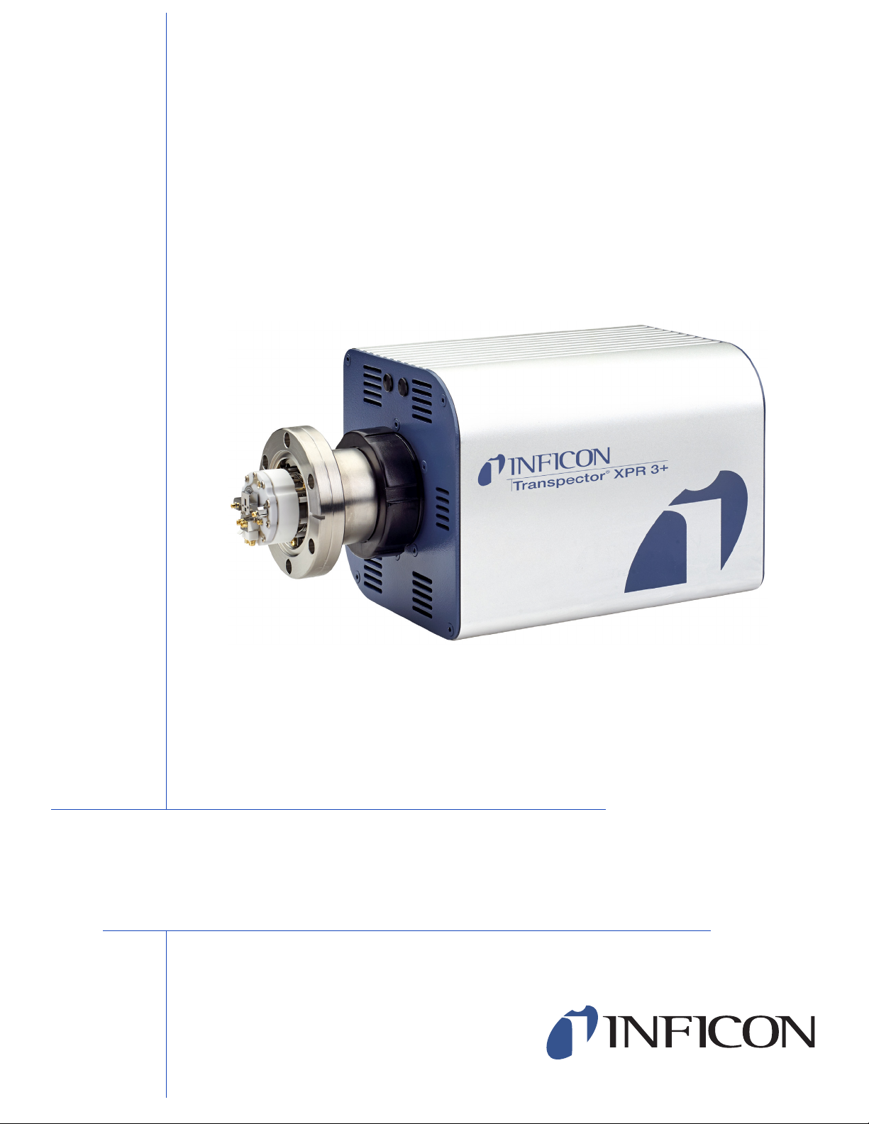
®
Transpector XPR 3+
Gas Analysis System
PN 074-687-P1A
Page 2

Declaration Of Conformity
Page 1
Page 3

Trademarks
The trademarks of the products mentioned in this manual are held by the companies that
produce them.
INFICON
®
, Transpector® and FabGuard® are registered trademarks of INFICON GmbH.
Windows®, and Microsoft® are registered trademarks of Microsoft Corporation.
All other brand names, product names or trademarks belong to their respective holders.
Software Copyrights
This product contains embedded software protected under the following copyrights:
Copyright INFICON Inc.
Disclaimer
The information contained in this Operating Manual is believed to be accurate and
reliable. However, INFICON assumes no responsibility for its use and shall not be liable
for any special, incidental, or consequential damages related to the use of this product.
Due to our continuing program of product improvements, specifications are subject to
change without notice.
Copyright
©2017 All rights reserved.
Reproduction or adaptation of any part of this document without permission is unlawful.
Page 4

Transpector XPR 3+ Operating Manual
Table Of Contents
Trademarks
Software Copyrights
Disclaimer
Copyright
Chapter 1
Getting Started
1.1 Introduction. . . . . . . . . . . . . . . . . . . . . . . . . . . . . . . . . . . . . . . . . . . . . . . . . . 1-1
1.2 Using This Manual . . . . . . . . . . . . . . . . . . . . . . . . . . . . . . . . . . . . . . . . . . . . 1-1
1.2.1 Note and Hint Paragraphs . . . . . . . . . . . . . . . . . . . . . . . . . . . . . . . . . . . . . . 1-1
1.2.2 Warning and Caution Paragraphs . . . . . . . . . . . . . . . . . . . . . . . . . . . . . . . . 1-2
1.3 How To Contact Customer Support . . . . . . . . . . . . . . . . . . . . . . . . . . . . . . . 1-2
1.3.1 Returning Transpector XPR 3+ to INFICON . . . . . . . . . . . . . . . . . . . . . . . . 1-3
1.4 Quick Start . . . . . . . . . . . . . . . . . . . . . . . . . . . . . . . . . . . . . . . . . . . . . . . . . . 1-3
1.5 Purpose of Transpector XPR 3+ Gas Analysis System . . . . . . . . . . . . . . . . 1-3
1.6 General Description of Transpector XPR 3+
Gas Analysis System . . . . . . . . . . . . . . . . . . . . . . . . . . . . . . . . . . . . . . . . . . 1-4
1.7 Specifications for Transpector XPR 3+ Gas Analysis System . . . . . . . . . . . 1-4
1.8 Supplied Items . . . . . . . . . . . . . . . . . . . . . . . . . . . . . . . . . . . . . . . . . . . . . . . 1-4
1.9 Physical Requirements. . . . . . . . . . . . . . . . . . . . . . . . . . . . . . . . . . . . . . . . . 1-5
1.9.1 Physical Dimensions . . . . . . . . . . . . . . . . . . . . . . . . . . . . . . . . . . . . . . . . . . 1-5
1.9.2 Weight . . . . . . . . . . . . . . . . . . . . . . . . . . . . . . . . . . . . . . . . . . . . . . . . . . . . . 1-6
1.9.3 Mounting Requirements . . . . . . . . . . . . . . . . . . . . . . . . . . . . . . . . . . . . . . . . 1-6
1.9.4 Ventilation Requirements . . . . . . . . . . . . . . . . . . . . . . . . . . . . . . . . . . . . . . . 1-6
1.9.5 Maintenance Access . . . . . . . . . . . . . . . . . . . . . . . . . . . . . . . . . . . . . . . . . . 1-6
1.10 Electrical Power Requirements . . . . . . . . . . . . . . . . . . . . . . . . . . . . . . . . . . 1-6
1.10.1 Required Supply Voltage . . . . . . . . . . . . . . . . . . . . . . . . . . . . . . . . . . . . . . . 1-6
1.10.2 Current Rating . . . . . . . . . . . . . . . . . . . . . . . . . . . . . . . . . . . . . . . . . . . . . . . 1-6
1.10.3 Electrical Connection . . . . . . . . . . . . . . . . . . . . . . . . . . . . . . . . . . . . . . . . . . 1-6
1.11 Overvoltage Category . . . . . . . . . . . . . . . . . . . . . . . . . . . . . . . . . . . . . . . . . 1-7
1.12 Required Vacuum. . . . . . . . . . . . . . . . . . . . . . . . . . . . . . . . . . . . . . . . . . . . . 1-7
1.13 Environmental Requirements . . . . . . . . . . . . . . . . . . . . . . . . . . . . . . . . . . . . 1-7
1.13.1 Use . . . . . . . . . . . . . . . . . . . . . . . . . . . . . . . . . . . . . . . . . . . . . . . . . . . . . . . . 1-7
1.13.2 Altitude Range . . . . . . . . . . . . . . . . . . . . . . . . . . . . . . . . . . . . . . . . . . . . . . . 1-7
1.13.3 Pollution Degree. . . . . . . . . . . . . . . . . . . . . . . . . . . . . . . . . . . . . . . . . . . . . . 1-7
1.13.4 Operating Temperature . . . . . . . . . . . . . . . . . . . . . . . . . . . . . . . . . . . . . . . . 1-8
TOC - 1
Page 5

Transpector XPR 3+ Operating Manual
1.13.5 Humidity . . . . . . . . . . . . . . . . . . . . . . . . . . . . . . . . . . . . . . . . . . . . . . . . . . . .1-8
1.14 Computer System Requirements . . . . . . . . . . . . . . . . . . . . . . . . . . . . . . . . .1-8
1.15 Software Installation . . . . . . . . . . . . . . . . . . . . . . . . . . . . . . . . . . . . . . . . . . . 1-8
1.16 Hardware Installation . . . . . . . . . . . . . . . . . . . . . . . . . . . . . . . . . . . . . . . . . .1-8
1.16.1 Avoiding Process Metal Deposition . . . . . . . . . . . . . . . . . . . . . . . . . . . . . . . 1-9
1.16.2 Installing the Isolation Valve. . . . . . . . . . . . . . . . . . . . . . . . . . . . . . . . . . . . 1-11
1.16.3 Mounting the Pirani Interlock Weldment Assembly . . . . . . . . . . . . . . . . . . 1-17
1.16.4 Mounting the Pirani Gauge. . . . . . . . . . . . . . . . . . . . . . . . . . . . . . . . . . . . . 1-18
1.16.5 Sensor Installation . . . . . . . . . . . . . . . . . . . . . . . . . . . . . . . . . . . . . . . . . . . 1-19
1.16.6 Electronics Module Installation . . . . . . . . . . . . . . . . . . . . . . . . . . . . . . . . . . 1-22
1.16.7 Initial Start-up Procedure . . . . . . . . . . . . . . . . . . . . . . . . . . . . . . . . . . . . . . 1-23
1.16.8 Installing Ethernet Communications . . . . . . . . . . . . . . . . . . . . . . . . . . . . . . 1-23
1.16.9 Connecting the 24 V(dc) Power Supply . . . . . . . . . . . . . . . . . . . . . . . . . . . 1-24
1.16.10 Connecting the Pirani Interlock Cable . . . . . . . . . . . . . . . . . . . . . . . . . . . . 1-24
1.16.11 Attaching Heating Jackets . . . . . . . . . . . . . . . . . . . . . . . . . . . . . . . . . . . . .1-25
1.17 Input/Output (I/O) . . . . . . . . . . . . . . . . . . . . . . . . . . . . . . . . . . . . . . . . . . . .1-25
1.17.1 Two Digital Inputs . . . . . . . . . . . . . . . . . . . . . . . . . . . . . . . . . . . . . . . . . . . . 1-26
1.17.2 One Status Relay Output . . . . . . . . . . . . . . . . . . . . . . . . . . . . . . . . . . . . . .1-26
1.17.3 One Analog Input . . . . . . . . . . . . . . . . . . . . . . . . . . . . . . . . . . . . . . . . . . . .1-28
Chapter 2
2.1 Introduction. . . . . . . . . . . . . . . . . . . . . . . . . . . . . . . . . . . . . . . . . . . . . . . . . . 2-1
2.2 General Networking Information. . . . . . . . . . . . . . . . . . . . . . . . . . . . . . . . . .2-1
2.2.1 IP Addresses . . . . . . . . . . . . . . . . . . . . . . . . . . . . . . . . . . . . . . . . . . . . . . . . 2-1
2.2.2 Subnetworking . . . . . . . . . . . . . . . . . . . . . . . . . . . . . . . . . . . . . . . . . . . . . . .2-3
2.3 Transpector XPR 3+ IP Address . . . . . . . . . . . . . . . . . . . . . . . . . . . . . . . . . 2-3
2.3.1 Changing Transpector XPR 3+ IP Address . . . . . . . . . . . . . . . . . . . . . . . . . 2-3
2.4 Connecting Transpector XPR 3+ . . . . . . . . . . . . . . . . . . . . . . . . . . . . . . . . 2-10
2.4.1 Connecting a Single Transpector XPR 3+ . . . . . . . . . . . . . . . . . . . . . . . . . 2-11
2.4.2 Installing Multiple Transpector XPR 3+ Sensors . . . . . . . . . . . . . . . . . . . . 2-11
Chapter 3
3.1 Introduction. . . . . . . . . . . . . . . . . . . . . . . . . . . . . . . . . . . . . . . . . . . . . . . . . . 3-1
3.2 Overview. . . . . . . . . . . . . . . . . . . . . . . . . . . . . . . . . . . . . . . . . . . . . . . . . . . .3-1
3.3 Patents . . . . . . . . . . . . . . . . . . . . . . . . . . . . . . . . . . . . . . . . . . . . . . . . . . . . . 3-1
3.4 Sensor . . . . . . . . . . . . . . . . . . . . . . . . . . . . . . . . . . . . . . . . . . . . . . . . . . . . .3-3
3.4.1 The Ion Source . . . . . . . . . . . . . . . . . . . . . . . . . . . . . . . . . . . . . . . . . . . . . . . 3-5
3.4.2 The Quadrupole Mass Filter . . . . . . . . . . . . . . . . . . . . . . . . . . . . . . . . . . . . .3-6
3.4.3 The Ion Detector. . . . . . . . . . . . . . . . . . . . . . . . . . . . . . . . . . . . . . . . . . . . . .3-8
Connecting Transpector XPR 3+
How The Instrument Works
TOC - 2
Page 6

3.5 Scanning Characteristics . . . . . . . . . . . . . . . . . . . . . . . . . . . . . . . . . . . . . . 3-10
3.6 The Zero Blast . . . . . . . . . . . . . . . . . . . . . . . . . . . . . . . . . . . . . . . . . . . . . . 3-11
3.7 High Pressure Effects. . . . . . . . . . . . . . . . . . . . . . . . . . . . . . . . . . . . . . . . . 3-11
Chapter 4
4.1 How to Interpret the Result. . . . . . . . . . . . . . . . . . . . . . . . . . . . . . . . . . . . . . 4-1
4.1.1 Qualitative Interpretation of Mass Spectra . . . . . . . . . . . . . . . . . . . . . . . . . . 4-1
4.1.2 Quantitative Interpretation of Mass Spectra
4.1.3 Additional Information for Interpreting Mass Spectra . . . . . . . . . . . . . . . . . 4-15
Chapter 5
5.1 Introduction. . . . . . . . . . . . . . . . . . . . . . . . . . . . . . . . . . . . . . . . . . . . . . . . . . 5-1
5.2 Precautions for Operation . . . . . . . . . . . . . . . . . . . . . . . . . . . . . . . . . . . . . . 5-2
5.3 Pirani Interlock Protection . . . . . . . . . . . . . . . . . . . . . . . . . . . . . . . . . . . . . . 5-2
5.4 FabGuard Control. . . . . . . . . . . . . . . . . . . . . . . . . . . . . . . . . . . . . . . . . . . . . 5-2
5.4.1 Transpector XPR 3+ Configuration— I/O Tab . . . . . . . . . . . . . . . . . . . . . . . 5-2
5.4.2 Transpector XPR 3+ BKM for Pirani Interlock Operation . . . . . . . . . . . . . . . 5-6
5.5 Using Transpector XPR 3+ . . . . . . . . . . . . . . . . . . . . . . . . . . . . . . . . . . . . . 5-7
5.5.1 Leak Detection . . . . . . . . . . . . . . . . . . . . . . . . . . . . . . . . . . . . . . . . . . . . . . . 5-7
5.5.2 Recipe Generation . . . . . . . . . . . . . . . . . . . . . . . . . . . . . . . . . . . . . . . . . . . . 5-7
5.5.3 Mass Scale Tuning. . . . . . . . . . . . . . . . . . . . . . . . . . . . . . . . . . . . . . . . . . . . 5-8
5.5.4 Transpector XPR 3+ Filament . . . . . . . . . . . . . . . . . . . . . . . . . . . . . . . . . . . 5-8
5.5.5 High Pressure Electron Multiplier . . . . . . . . . . . . . . . . . . . . . . . . . . . . . . . . . 5-8
Transpector XPR 3+ Operating Manual
Applications Guide
(Calculating Partial Pressures). . . . . . . . . . . . . . . . . . . . . . . . . . . . . . . . . . . 4-9
Transpector XPR 3+ Operation and Best Known Methods
Chapter 6
TOC - 3
Transpector XPR 3+ Low Pressure EM
6.1 Introduction. . . . . . . . . . . . . . . . . . . . . . . . . . . . . . . . . . . . . . . . . . . . . . . . . . 6-1
6.2 Transpector XPR 3+ Filament Caution . . . . . . . . . . . . . . . . . . . . . . . . . . . . 6-1
6.3 Electron Multiplier Caution . . . . . . . . . . . . . . . . . . . . . . . . . . . . . . . . . . . . . . 6-1
6.4 Quick Start . . . . . . . . . . . . . . . . . . . . . . . . . . . . . . . . . . . . . . . . . . . . . . . . . . 6-2
6.5 Purpose of the Transpector XPR 3+ Low Pressure EM Option
Gas Analysis System . . . . . . . . . . . . . . . . . . . . . . . . . . . . . . . . . . . . . . . . . . 6-2
6.6 General Description of Transpector XPR 3+ Low Pressure EM
Option Gas Analysis System . . . . . . . . . . . . . . . . . . . . . . . . . . . . . . . . . . . . 6-3
6.7 Specifications for Transpector XPR 3+ Low Pressure EM Option
Gas Analysis System . . . . . . . . . . . . . . . . . . . . . . . . . . . . . . . . . . . . . . . . . . 6-4
6.8 Supplied Items . . . . . . . . . . . . . . . . . . . . . . . . . . . . . . . . . . . . . . . . . . . . . . . 6-5
6.9 XPR 3+ Low Pressure EM Installation . . . . . . . . . . . . . . . . . . . . . . . . . . . . . 6-5
6.10 XPR 3+ Low Pressure EM Operation. . . . . . . . . . . . . . . . . . . . . . . . . . . . . . 6-5
Page 7

Chapter 7
7.1 Introduction. . . . . . . . . . . . . . . . . . . . . . . . . . . . . . . . . . . . . . . . . . . . . . . . . . 7-1
7.2 Safety Considerations . . . . . . . . . . . . . . . . . . . . . . . . . . . . . . . . . . . . . . . . . 7-1
7.2.1 Toxic Material . . . . . . . . . . . . . . . . . . . . . . . . . . . . . . . . . . . . . . . . . . . . . . . . 7-1
7.2.2 Radiation . . . . . . . . . . . . . . . . . . . . . . . . . . . . . . . . . . . . . . . . . . . . . . . . . . . 7-1
7.2.3 Electrical Voltages . . . . . . . . . . . . . . . . . . . . . . . . . . . . . . . . . . . . . . . . . . . .7-2
7.3 General Instructions For All Repair Procedures . . . . . . . . . . . . . . . . . . . . . . 7-2
7.4 Maintenance Procedures . . . . . . . . . . . . . . . . . . . . . . . . . . . . . . . . . . . . . . .7-3
7.4.1 Bakeout of Quadrupole. . . . . . . . . . . . . . . . . . . . . . . . . . . . . . . . . . . . . . . . . 7-3
7.4.2 Spare Heating Jacket Part Numbers . . . . . . . . . . . . . . . . . . . . . . . . . . . . . . 7-3
7.5 Repair Procedures . . . . . . . . . . . . . . . . . . . . . . . . . . . . . . . . . . . . . . . . . . . .7-4
7.5.1 Tools Required . . . . . . . . . . . . . . . . . . . . . . . . . . . . . . . . . . . . . . . . . . . . . . . 7-4
7.5.2 How to Determine if a Filament Kit Replacement is Required . . . . . . . . . . . 7-5
7.5.3 Filament Kit Replacement . . . . . . . . . . . . . . . . . . . . . . . . . . . . . . . . . . . . . . 7-5
7.5.4 How to Determine the Condition of the Ion Source . . . . . . . . . . . . . . . . . . . 7-7
7.6 Mass Calibration. . . . . . . . . . . . . . . . . . . . . . . . . . . . . . . . . . . . . . . . . . . . . . 7-9
7.6.1 Mass Alignment . . . . . . . . . . . . . . . . . . . . . . . . . . . . . . . . . . . . . . . . . . . . . .7-9
7.7 Pirani Interlock Adjustment Procedures . . . . . . . . . . . . . . . . . . . . . . . . . . . 7-10
7.7.1 INFICON PSG500 Adjustment Instructions . . . . . . . . . . . . . . . . . . . . . . . . 7-10
Transpector XPR 3+ Operating Manual
Maintenance
Chapter 8
8.1 Introduction. . . . . . . . . . . . . . . . . . . . . . . . . . . . . . . . . . . . . . . . . . . . . . . . . . 8-1
8.2 Symptom-Cause-Remedy Chart . . . . . . . . . . . . . . . . . . . . . . . . . . . . . . . . . 8-1
8.3 Communication Problems . . . . . . . . . . . . . . . . . . . . . . . . . . . . . . . . . . . . . . 8-6
Chapter 9
Chapter 10
Chapter 11
11.1 Introduction. . . . . . . . . . . . . . . . . . . . . . . . . . . . . . . . . . . . . . . . . . . . . . . . .11-1
11.2 Transpector XPR 3+ Accessories . . . . . . . . . . . . . . . . . . . . . . . . . . . . . . .11-1
11.3 Transpector XPR 3+ Spare Parts. . . . . . . . . . . . . . . . . . . . . . . . . . . . . . . . 11-2
11.3.1 Preventative Maintenance Parts. . . . . . . . . . . . . . . . . . . . . . . . . . . . . . . . .11-2
11.3.2 Replacement Spare Parts . . . . . . . . . . . . . . . . . . . . . . . . . . . . . . . . . . . . . 11-2
Diagnosing Problems
Bibliography
Glossary
Transpector XPR 3+ Accessories and Spare Parts
TOC - 4
Page 8

Chapter 12
12.1 Introduction. . . . . . . . . . . . . . . . . . . . . . . . . . . . . . . . . . . . . . . . . . . . . . . . . 12-1
12.2 Mass Range . . . . . . . . . . . . . . . . . . . . . . . . . . . . . . . . . . . . . . . . . . . . . . . . 12-1
12.3 Detector Type. . . . . . . . . . . . . . . . . . . . . . . . . . . . . . . . . . . . . . . . . . . . . . . 12-1
12.4 Resolution . . . . . . . . . . . . . . . . . . . . . . . . . . . . . . . . . . . . . . . . . . . . . . . . . 12-1
12.5 Temperature Coefficient. . . . . . . . . . . . . . . . . . . . . . . . . . . . . . . . . . . . . . . 12-1
12.6 Sensitivity . . . . . . . . . . . . . . . . . . . . . . . . . . . . . . . . . . . . . . . . . . . . . . . . . . 12-2
12.7 Minimum Detectable Partial Pressure . . . . . . . . . . . . . . . . . . . . . . . . . . . . 12-2
12.8 Maximum Operating Pressure . . . . . . . . . . . . . . . . . . . . . . . . . . . . . . . . . . 12-2
12.9 Maximum Sensor Operating Temperature . . . . . . . . . . . . . . . . . . . . . . . . . 12-2
12.10 Maximum Bakeout Temperature . . . . . . . . . . . . . . . . . . . . . . . . . . . . . . . . 12-3
12.11 Operating Temperature . . . . . . . . . . . . . . . . . . . . . . . . . . . . . . . . . . . . . . . 12-3
12.12 Power Input . . . . . . . . . . . . . . . . . . . . . . . . . . . . . . . . . . . . . . . . . . . . . . . . 12-3
12.13 Ethernet Communication Interface. . . . . . . . . . . . . . . . . . . . . . . . . . . . . . . 12-3
12.14 Relay Outputs. . . . . . . . . . . . . . . . . . . . . . . . . . . . . . . . . . . . . . . . . . . . . . . 12-3
12.15 Inputs . . . . . . . . . . . . . . . . . . . . . . . . . . . . . . . . . . . . . . . . . . . . . . . . . . . . . 12-3
12.16 Indicators (Green) . . . . . . . . . . . . . . . . . . . . . . . . . . . . . . . . . . . . . . . . . . . 12-3
Transpector XPR 3+ Operating Manual
Specifications
Chapter 13
13.1 Introduction. . . . . . . . . . . . . . . . . . . . . . . . . . . . . . . . . . . . . . . . . . . . . . . . . 13-1
13.1.1 Ship Kit . . . . . . . . . . . . . . . . . . . . . . . . . . . . . . . . . . . . . . . . . . . . . . . . . . . . 13-1
13.1.2 Electronics Module. . . . . . . . . . . . . . . . . . . . . . . . . . . . . . . . . . . . . . . . . . . 13-2
13.1.3 Power Supply . . . . . . . . . . . . . . . . . . . . . . . . . . . . . . . . . . . . . . . . . . . . . . . 13-2
13.1.4 Sensor . . . . . . . . . . . . . . . . . . . . . . . . . . . . . . . . . . . . . . . . . . . . . . . . . . . . 13-3
13.1.5 Software . . . . . . . . . . . . . . . . . . . . . . . . . . . . . . . . . . . . . . . . . . . . . . . . . . . 13-3
13.1.6 Heating Jacket System (Optional) . . . . . . . . . . . . . . . . . . . . . . . . . . . . . . . 13-3
13.1.7 Interlock Kit (Optional) . . . . . . . . . . . . . . . . . . . . . . . . . . . . . . . . . . . . . . . . 13-3
13.1.8 Angle Valve (Optional) . . . . . . . . . . . . . . . . . . . . . . . . . . . . . . . . . . . . . . . . 13-4
Index
Supplied Items
TOC - 5
Page 9

Chapter 1 Getting Started
1.1 Introduction
Transpector XPR 3+ Gas Analysis System is a quadrupole-based mass
spectrometer Residual Gas Analysis (RGA) instrument designed for use in high
vacuum environments, up to 20 mTorr, for monitoring trace contaminants and
process gases. Transpector XPR 3+ runs with the Windows
using a member of the FabGuard
This chapter provides an overview of Transpector XPR 3+ Gas Analysis System.
Topics include:
the purpose of Transpector XPR 3+
specifications
®
suite of programs.
Transpector XPR 3+ Operating Manual
®
operating system
a list of supplied items
installation instructions
customer support contact information.
Software information can be found either in the FabGuard Explorer Operating
Manual (PN 074-528-P1) or in the FabGuard help files (for all other FabGuard
programs).
1.2 Using This Manual
Please read this Operating Manual before operating Transpector XPR 3+.
1.2.1 Note and Hint Paragraphs
NOTE: This is a note paragraph. Notes provide additional information about the
current topic.
HINT: This is a hint paragraph. Hints provide insight into product usage.
1 - 1
Page 10

1.2.2 Warning and Caution Paragraphs
CAUTION
WARNING
WARNING - Risk Of Electric Shock
The following Caution and Warning paragraphs are used to alert the reader of
actions which may cause either damage to the instrument or bodily injury.
This is an example of a Caution paragraph. It cautions against actions which may cause an instrument malfunction or the loss of data.
This is an example of a General Warning paragraph. It warns against actions which may cause bodily injury.
Transpector XPR 3+ Operating Manual
This is an example of a Electrical Warning paragraph. It warns of the presence of electrical voltages which may cause bodily injury.
1.3 How To Contact Customer Support
Worldwide customer support information is available under Contact >> Support
Worldwide at www.inficon.com:
Sales and Customer Service
Technical Support
Repair Service
If you are experiencing a problem with Transpector XPR 3+, please have the
following information readily available:
the Transpector XPR 3+ serial number
a description of the problem
an explanation of any corrective action already attempted
1 - 2
the exact wording of any error messages
Page 11

1.3.1 Returning Transpector XPR 3+ to INFICON
Do not return any component of Transpector XPR 3+ to INFICON before speaking
with a Customer Support Representative and obtaining a Return Material
Authorization (RMA) number. Transpector XPR 3+ will not be serviced without an
RMA number.
Prior to being given an RMA number, a Declaration Of Contamination (DOC) form
may need to be completed if the sensor has been exposed to process materials.
DOC forms must be approved by INFICON before an RMA number is issued.
INFICON may require that the sensor be sent to a designated decontamination
facility, not to the factory.
1.4 Quick Start
Read this Operating Manual in full prior to operating Transpector XPR 3+. Then,
follow the steps below to quickly start using Transpector XPR 3+.
1 Ensure that all supplied items have been received. See Chapter 13,
Supplied Items.
Transpector XPR 3+ Operating Manual
2 Install the hardware. See section 1.16, Hardware Installation, on page 1-8.
3 Install the communication cable. See section 1.16.8, Installing Ethernet
Communications, on page 1-23.
4 Install the software. Refer to the FabGuard Explorer Operating Manual for
information on installing the software.
NOTE: Transpector XPR 3+ requires FabGuard version 17.04.00 or higher for
operation.
1.5 Purpose of Transpector XPR 3+ Gas Analysis System
Transpector XPR 3+ Gas Analysis System is a quadrupole-based residual gas
analyzer that operates at Physical Vapor Deposition (PVD) process pressures and
has an Electron Multiplier that can operate at 20 mTorr operating pressures. The
miniature quadrupole sensor analyzes gases by:
ionizing some of the gas molecules
separating the ions by their mass-to-charge ratio
measuring the quantity of ions at each mass
The masses, unique for each substance, allow the identification of the gas
molecules from which the ions were created. The magnitudes of these signals are
used to determine the partial pressures (amounts) of the respective gases.
Transpector XPR 3+ measures major components and impurities in a process with
a 10 ppm detection limit.
1 - 3
Page 12

Transpector XPR 3+ Operating Manual
Transpector XPR 3+ is an important aid in the efficient use of a high-vacuum
system, detecting leaks, and contaminants. It can indicate the partial pressures of
gases in processes occurring within a vacuum or other vessel, and therefore, can
be used to investigate the nature of a process or monitor process conditions.
1.6 General Description of Transpector XPR 3+ Gas Analysis System
Transpector XPR 3+ Gas Analysis System is comprised of three parts:
Sensor
The sensor, which functions only in a high-vacuum environment with pressures
below 2x10
The sensor itself is comprised of three components:
the ion source (ionizer)
the quadrupole mass filter
the ion detector
The sensor is mounted on an electrical feedthrough flange, which is bolted to
the vacuum chamber where the gas analysis measurements are made.
Electronics Module
The electronics module controls the sensor and communicates to the operating
computer. The electronics module and sensor are sold matched in sets. The
electronics module attaches to and is supported by the sensor.
Software
The software controls the electronics module and displays the data
from the sensor.
-2
Torr (2.66 x 10⁻² mbar) [2.66 Pascals].
1.7 Specifications for Transpector XPR 3+ Gas Analysis System
See Chapter 12 for Transpector XPR 3+ Gas Analysis System specifications.
1.8 Supplied Items
See Chapter 13 for items that are packaged with Transpector XPR 3+
Gas Analysis System.
1 - 4
Page 13
1.9 Physical Requirements
The following sections show the physical dimensions, weight, mounting
requirements, ventilation requirements, and the perimeter required for
maintenance access for Transpector XPR 3+.
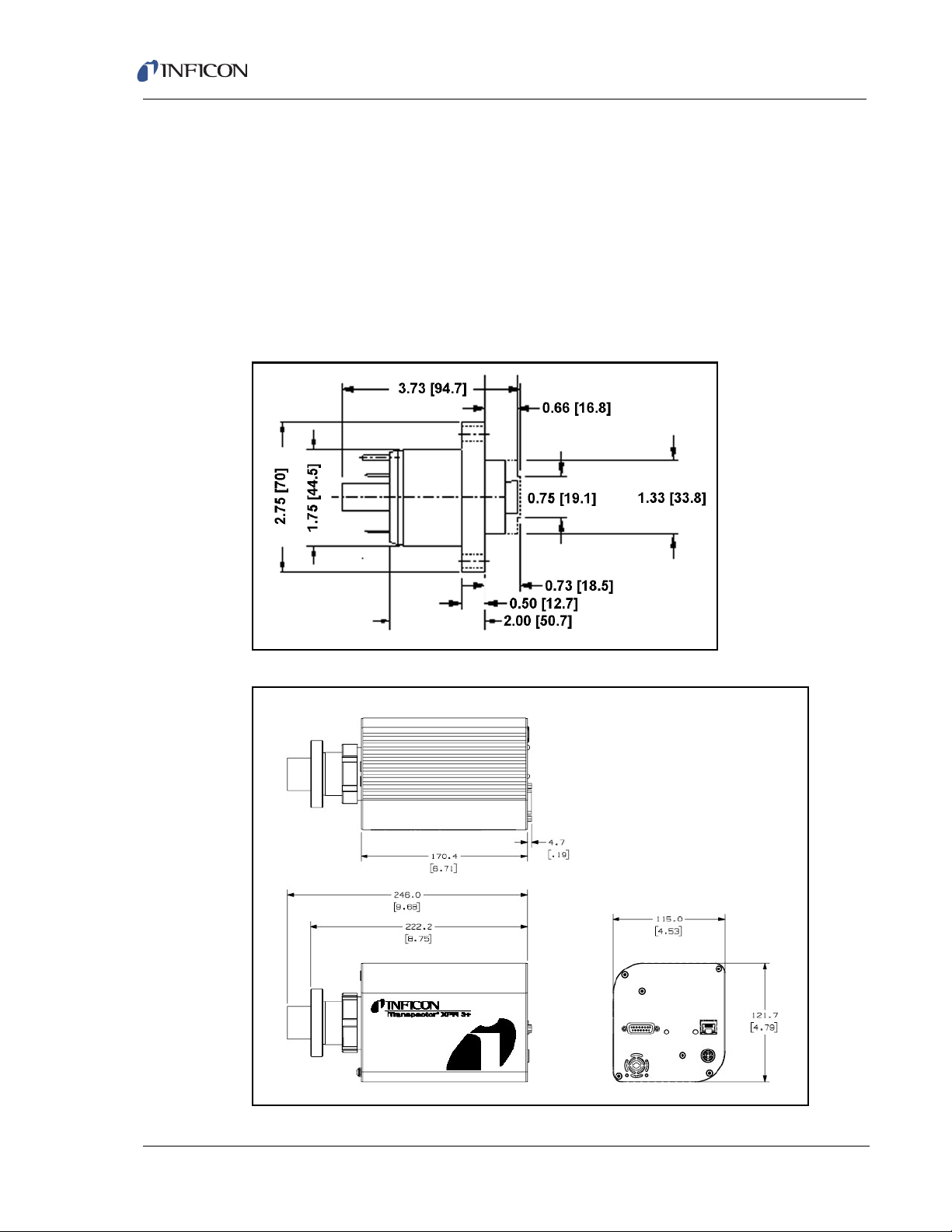
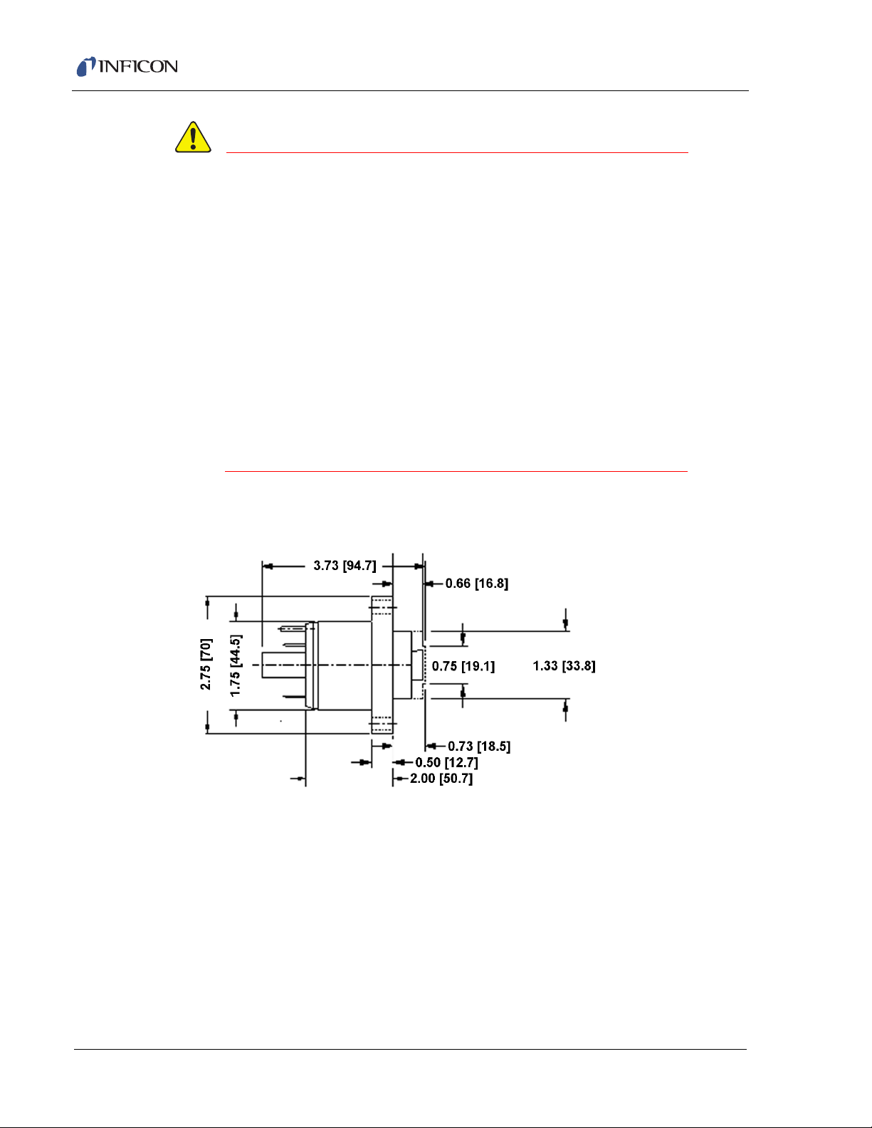
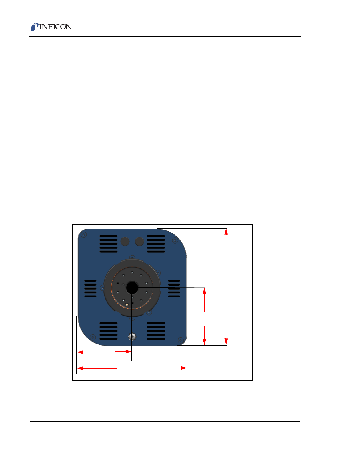
1.9.1 Physical Dimensions
Figure 1-2 shows the overall physical dimensions of Transpector XPR 3+ in inches
[millimeters].
Figure 1-1 Sensor dimensions
Transpector XPR 3+ Operating Manual
Figure 1-2 Physical dimensions of Transpector XPR 3+
1 - 5
Page 14

1.9.2 Weight
Transpector XPR 3+ electronics module weighs 1.62 kg (3.58 lbs).
1.9.3 Mounting Requirements
The sensor is mounted to a high-vacuum chamber with a standard 2.75 in.
(69.9 mm) O.D. ConFlat flange.
The electronics module attaches to and is supported by the sensor.
Transpector XPR 3+ can be mounted in any position. See section 1.16.5, Sensor
Installation, on page 1-19 for information on installing Transpector XPR 3+ system.
1.9.4 Ventilation Requirements
At least 25.4 mm (1 in.) of open space around the Transpector XPR 3+ electronics
module must be maintained for proper ventilation.
1.9.5 Maintenance Access
Easy access to Transpector XPR 3+ should be maintained for installation and
maintenance activities.
Transpector XPR 3+ Operating Manual
1.10 Electrical Power Requirements
Transpector XPR 3+ must be connected to a source of power as specified in the
following sections.
1.10.1 Required Supply Voltage
20 to 30 V(dc), 24 V(dc) typical
1.10.2 Current Rating
1.25 A maximum
1.10.3 Electrical Connection
Latching, 4-pin DIN connector, internally isolated from system ground.
See Figure 1-3.
1 - 6
Page 15
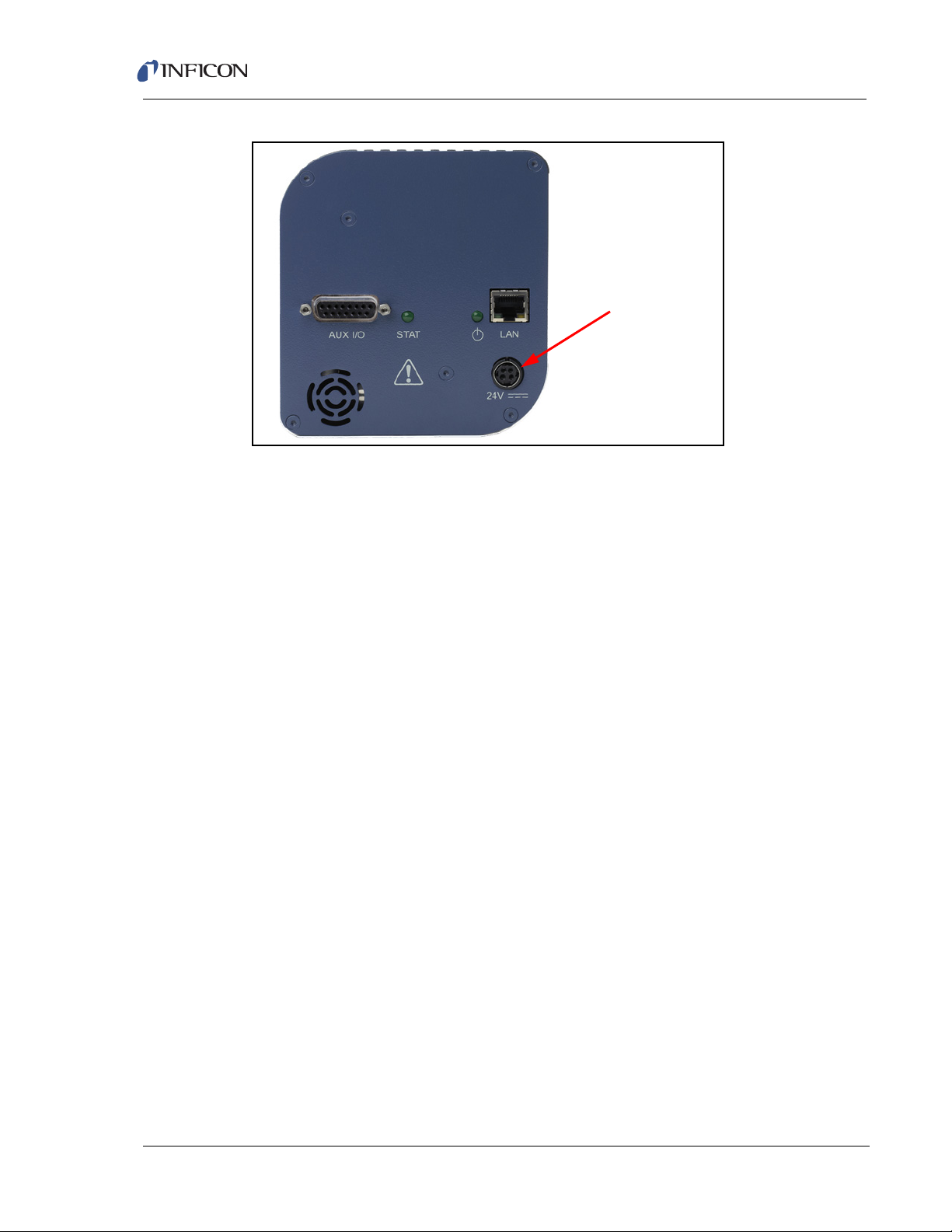
Figure 1-3 Transpector XPR 3+ connections
Electrical Connection
1.11 Overvoltage Category
Transpector XPR 3+ Operating Manual
Overvoltage Category II (per EN61010-1)
1.12 Required Vacuum
Transpector XPR 3+: < 2.0x10⁻² Torr (2.66x10⁻² mbar) [2.66 Pascals]
1.13 Environmental Requirements
The following paragraphs explain the use, altitude range, humidity, pollution
degree, and operating temperature for Transpector XPR 3+.
1.13.1 Use
Transpector XPR 3+ is designed for indoor use only.
1.13.2 Altitude Range
Transpector XPR 3+ can be used up to a maximum altitude range of
2000 m (6561 ft.).
1.13.3 Pollution Degree
Pollution Degree 2 (per EN61010-1)
1 - 7
Page 16

1.13.4 Operating Temperature
Transpector XPR 3+ is designed to operate within a temperature range of
5°C to 50°C (41°F to 122°F).
1.13.5 Humidity
Transpector XPR 3+ is designed to operate in an environment with up to
98% relative humidity.
1.14 Computer System Requirements
Refer to the FabGuard Explorer Operating Manual (PN 074-528-P1) for computer
system requirements.
1.15 Software Installation
Refer to the FabGuard Explorer Operating Manual (PN 074-528-P1) for information
on installing the software and setting up the protocols necessary to ensure proper
software operation.
Transpector XPR 3+ Operating Manual
1.16 Hardware Installation
The following steps must be performed to install Transpector XPR 3+
Gas Analysis System.
1 If the optional Isolation Valve option was purchased with the
Transpector XPR 3+ install the Isolation Valve, see section 1.16.2 on page
1-11.
2 If the optional Pirani Gauge Interlock was purchased with the
Transpector XPR 3+ mount the Pirani Interlock Weldment Assembly, see
section 1.16.3 on page 1-17.
3 If the optional Pirani Gauge Interlock was purchased with the
Transpector XPR 3+ mount the Pirani Gauge, see section 1.16.4 on page
1-18.
4 Install the Transpector XPR 3+ Sensor, see section 1.16.5 on page 1-19.
5 Install the Transpector Electronics Module, see section 1.16.6 on page 1-22.
6 Install the Communications cables, see section 1.16.8 on page 1-23.
7 Install the 24 V DC Power Supply, see section 1.16.9 on page 1-24.
8 If the optional Pirani Gauge Interlock was purchased with the
Transpector XPR 3+ install the Transpector XPR 3+ Interlock Cable, see
section 1.16.10 on page 1-24.
1 - 8
Page 17

9 If the optional Pirani Gauge Interlock and/or the optional Isolation Valve were
CAUTION
CAUTION
purchased with the Transpector XPR 3+ attach the Heating Jackets, see
section 1.16.11 on page 1-25
10 Install the Software.
1.16.1 Avoiding Process Metal Deposition
Conductive deposits on the ceramic ion source plate
from the process can cause electrical short circuits and
a general failure of Transpector XPR 3+. The use of a 90
valve between the process and the sensor will alleviate
this condition. The installation of a 90
in ConFlat Flanges.
The sensor is installed on a vacuum system with a 2.75 in. DN40 ConFlat flange.
ConFlat flanges, and similar compatible types made by other manufacturers, are
used for attaching devices to ports on high vacuum systems. If there are no
concerns with the installation of this type of flange, proceed to section 1.16.5.1,
Attaching the Sensor to the Vacuum Chamber, on page 1-19.
Transpector XPR 3+ Operating Manual
o
o
valve is described
NOTE: If the system does not have a port with a compatible mating flange, an
adapter will be necessary.
To install these flanges without leaks, follow proper operating procedures. These
flanges are sealed with a metal gasket and can be heated for bakeout to
temperatures of up to 200°C. For bakeout temperatures when a sensor is installed,
see Table 1-1 on page 1-21.
1.16.1.1 Assembling ConFlat Flanges
To assemble a pair of ConFlat flanges:
1 Wipe the sealing areas of the flanges with a laboratory towel using a clean
solvent, such as water free alcohol. These areas must be clean and free of
particulate matter.
Do not touch any surface on the gasket and flange faces with bare fingers. If it is necessary to touch any of these parts, always wear clean linen, nylon, powder free latex or vinyl laboratory gloves.
1 - 9
Page 18
Transpector XPR 3+ Operating Manual
CAUTION
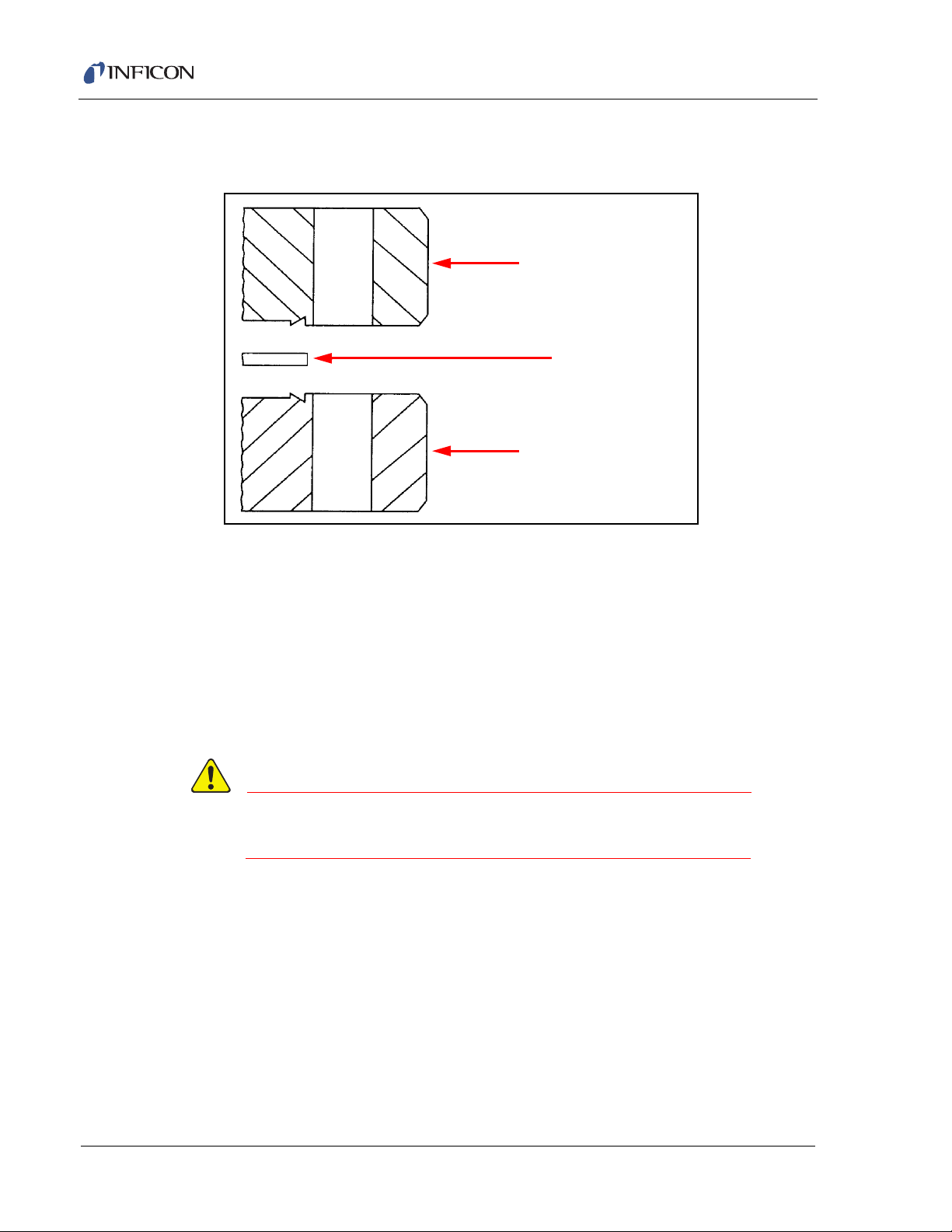
Flange
Flange
Copper Gasket
2 Install the copper gasket between the two flanges. (See Figure 1-4.) Always
use a new gasket. Do not attempt to use gaskets more than once.
Figure 1-4 Gasket and flange assembly
3 Bring the two flanges together making sure that the gasket fits in the recess in
both flanges. Flange faces should be parallel. If the gasket is properly seated, it
should not be possible to slide the two flanges laterally with respect to each other.
4 Install supplied silver-coated stainless steel bolts in the bolt holes of the flanges
and finger-tighten.
NOTE: If the factory-supplied silver-coated stainless steel hardware is not
used and the flanges are going to be baked, coat the bolt threads with
®
an anti-seize compound (FelPro
C 100 or equivalent).
Do not get any of the anti-seize compound on the gaskets or vacuum parts of the flange.
5 After the bolts have been finger-tightened and the flange faces are parallel,
tighten the bolts gradually and evenly in a star pattern until the flange faces are
brought into even contact with each other.
1 - 10
Page 19
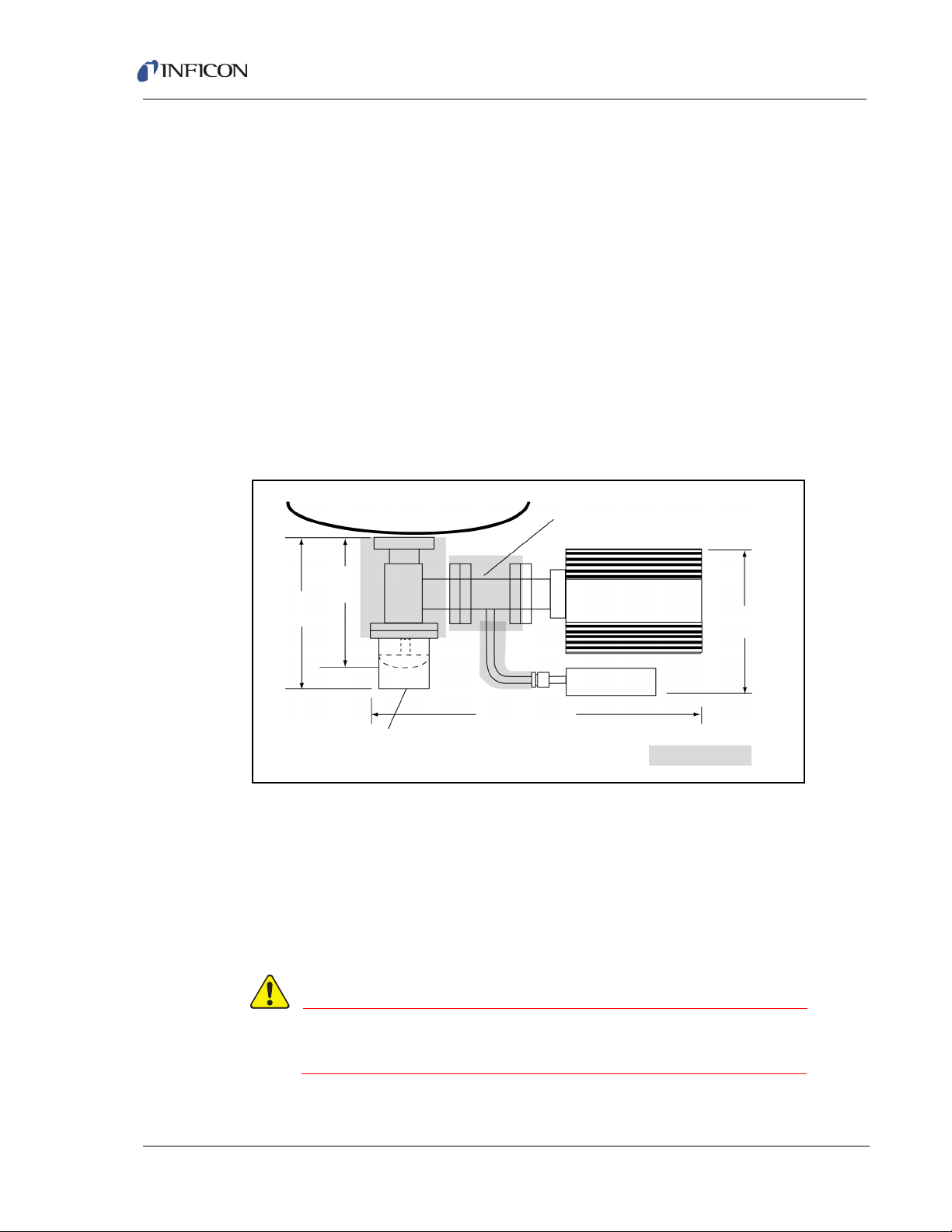
1.16.2 Installing the Isolation Valve
WARNING
Tool
Interlock Weldment
IPN 914-416-G1
16.71 in. (42.5 cm)
Pirani Gauge
8.3 in.
(21 cm)
7.2 in.
(18 cm)
Transpector XPR 3+
8.0 in.
(20.4 cm)
The 90° Isolation Valve is
located between the Tool
Chamber and Transpector XPR 3+.
IPN 918-401-P1
Manual
Air Operated
Heating Jackets
Transpector XPR 3+ should be installed on a 90° high-conductance isolation valve
(1.5 in. [38 mm] outer diameter) mounted on the process chamber. This prevents
line-of-sight deposits, from the plasma, from reaching the Transpector XPR 3+
Sensor. (See Figure 1-5.) The isolation valve may be provided by the user, or
purchased from INFICON (see below). The isolation valve must be bakeable and
needs to be fitted with a heating jacket designed for baking the valve.
1½" Right Angle Valve Hand Operated with Heating Jacket:
IPN 914-024-G1
1½" Right Angle Valve Air Operated with 24 V(dc) Solenoid and
Heating Jacket: IPN 961-025-G1
Valve Heating Jacket (150 °C; 120/230 V(ac) Operation):
IPN 914-407-P1
Figure 1-5 Typical Connection of a Transpector XPR 3+ to the process chamber
Transpector XPR 3+ Operating Manual
1.16.2.1 Notes for Air Operated Valve
The INFICON supplied air operated valve is a 1/8 in. ported, 3-way, single solenoid,
2-position spring return, Normally Open (NO) or Normally Closed (NC), general
purpose air valve. It is configured for 2-way, NC use, whereby the EXH port is
plugged and the air supply (60 - 100 psig) must be connected to the port
labeled IN. (See Figure 1-6.)
The air pressure supplied to the valve must not exceed 100 psig.
1 - 11
Page 20
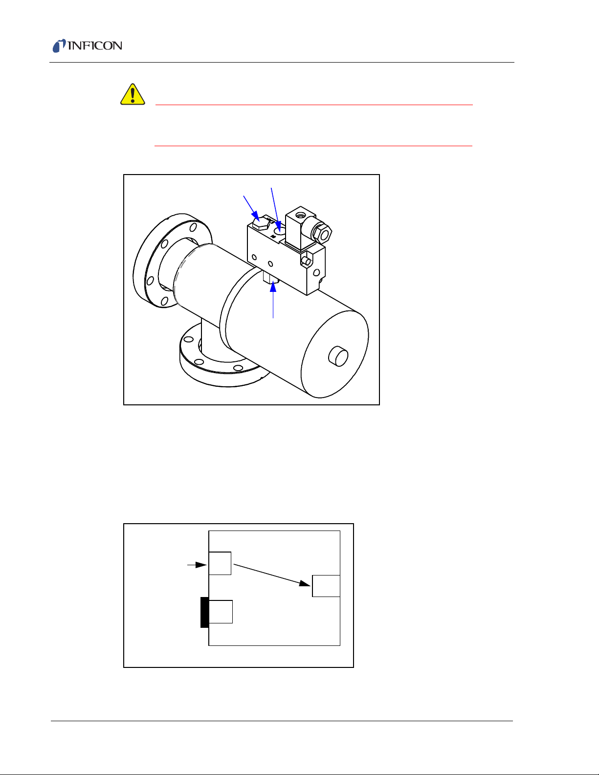
CAUTION
The air pressure supplied to the valve must be at least
EXH
IN
OUT
IN
OUT
EXH
2 WAY NORMALLY CLOSED
PLUGGED
INLET
AIR
60 psig.
Figure 1-6 INFICON supplied air valve
Transpector XPR 3+ Operating Manual
1.16.2.2 Port Identification for 2-Way, Normally Closed Use
See Figure 1-7.
IN . . . . . . . . . . . . . . . . . . . . . . . . . . . Pressure supply port
OUT . . . . . . . . . . . . . . . . . . . . . . . . . Delivery port to valve
EXH . . . . . . . . . . . . . . . . . . . . . . . . . Exhaust port, plugged
Figure 1-7 Port identification
1 - 12
Page 21
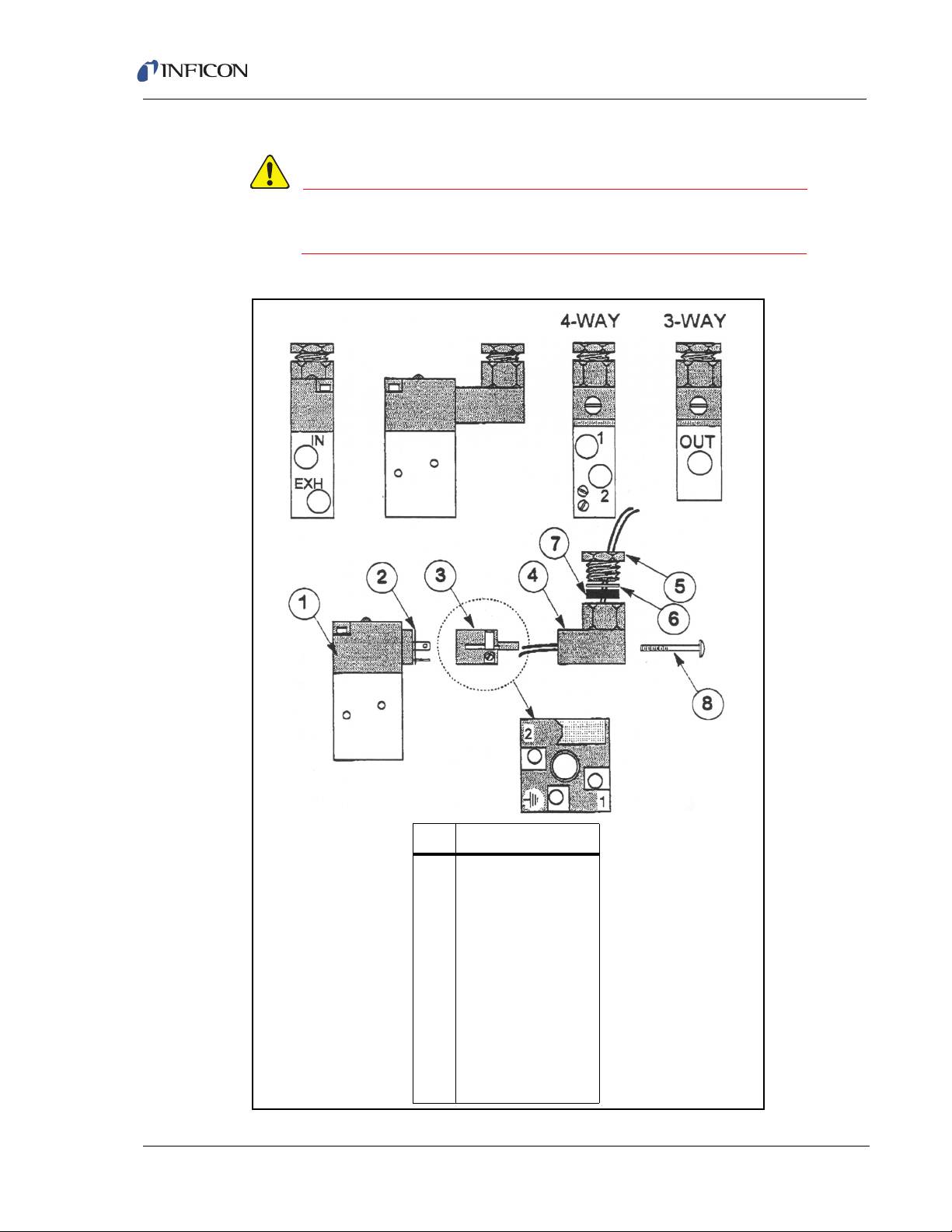
1.16.2.3 Valve Parts List
WARNING
Item Description
1 Solenoid Coil
2 Connector Gasket
3 Connector
4 Connector Elbow
5Nut
6 Washer
7 Compression Ring
8Screw
This valve has an operational voltage rating of 24 V(dc) +10% to -15%.
Figure 1-8 Valve parts list
Transpector XPR 3+ Operating Manual
1 - 13
Page 22
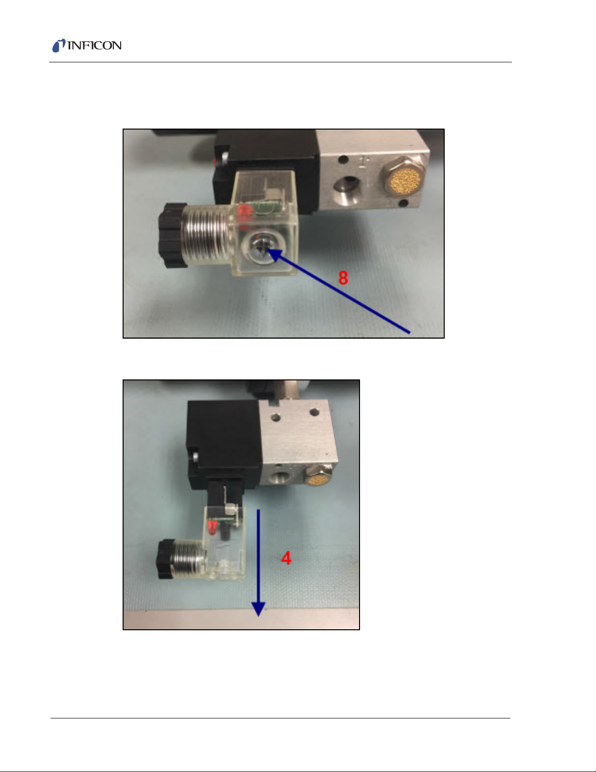
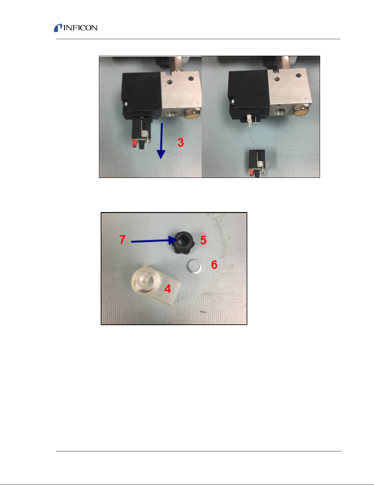
1.16.2.4 Wiring Instructions
1 Remove the screw (8).
Figure 1-9 Removing connector assembly
Transpector XPR 3+ Operating Manual
2 Remove the clear plastic connector elbow (4).
Figure 1-10 Removing connector elbow
1 - 14
3 Remove the connector (3) from the solenoid assembly, be careful to not
remove the connector gasket (2).
Page 23
Transpector XPR 3+ Operating Manual
Figure 1-11 Removing connector terminal
4 Remove the black plastic nut (5) from the connector elbow (4), the washer (6)
and the compression ring (7) can stay in place.
Figure 1-12 Connect elbow assembly
5 Take the MMSP Valve/Relay Interface Cable (IPN 600-1450-P2) and run the
cables through the nut (5), washer (6), compression ring (7) and the connector
elbow (4).
1 - 15
Page 24

Transpector XPR 3+ Operating Manual
4
6
5
7
Figure 1-13 Cable and connector elbow feed
6 Connect the red and black wires to terminals 1 and 2 in either order. This can
be done by soldering the wires in place or using the appropriate screw
terminals on the connector (3) assembly.
Figure 1-14 Connecting the red and black wires to the terminal
1 - 16
7 Press the connector (3) back into the connector elbow (4) screw the nut (5)
securely into place. Connect the connector (3) to the solenoid coil (1) noting the
connection scheme NOTE: When fitting the connector (3) into the connector
elbow (4) note the orientation of the connection to the solenoid coil (1). Ideally
the elbow should be facing away from the inlet air connection point as it can
interfere with the connection of the inlet air.
Page 25

Transpector XPR 3+ Operating Manual
Figure 1-15 Connecting the connector
8 Screw the assembly back into the solenoid coil using the screw (8) removed in
step 1.
Figure 1-16 Screw the assembly back into the solenoid coil
1.16.3 Mounting the Pirani Interlock Weldment Assembly
Transpector XPR 3+ Interlock Weldment Assembly with a Pirani gauge port has a
1.5 in. (38 mm) inner diameter for the Transpector XPR 3+ sensor. Both CF-40
flanges rotate to provide flexibility in orientation of the Pirani gauge with respect to
the Transpector electronics module, the isolation valve, and the tool.
1 Evaluate, or pre-fit, Transpector XPR 3+ on the tool port to determine the
orientation of the Transpector electronics module with respect to the tool, and
the Pirani gauge with respect to a side of the Transpector electronics module.
Typically, the Pirani gauge is placed under the Transpector electronics module
if the axis of Transpector XPR 3+ is horizontal, as shown in Figure 1-17.
NOTE: For measurements of 2x10
of the Transpector XPR 3+ filament, the Pirani gauge retains its
accuracy in any orientation.
-2
Torr or less, that are involved in protection
1 - 17
Page 26
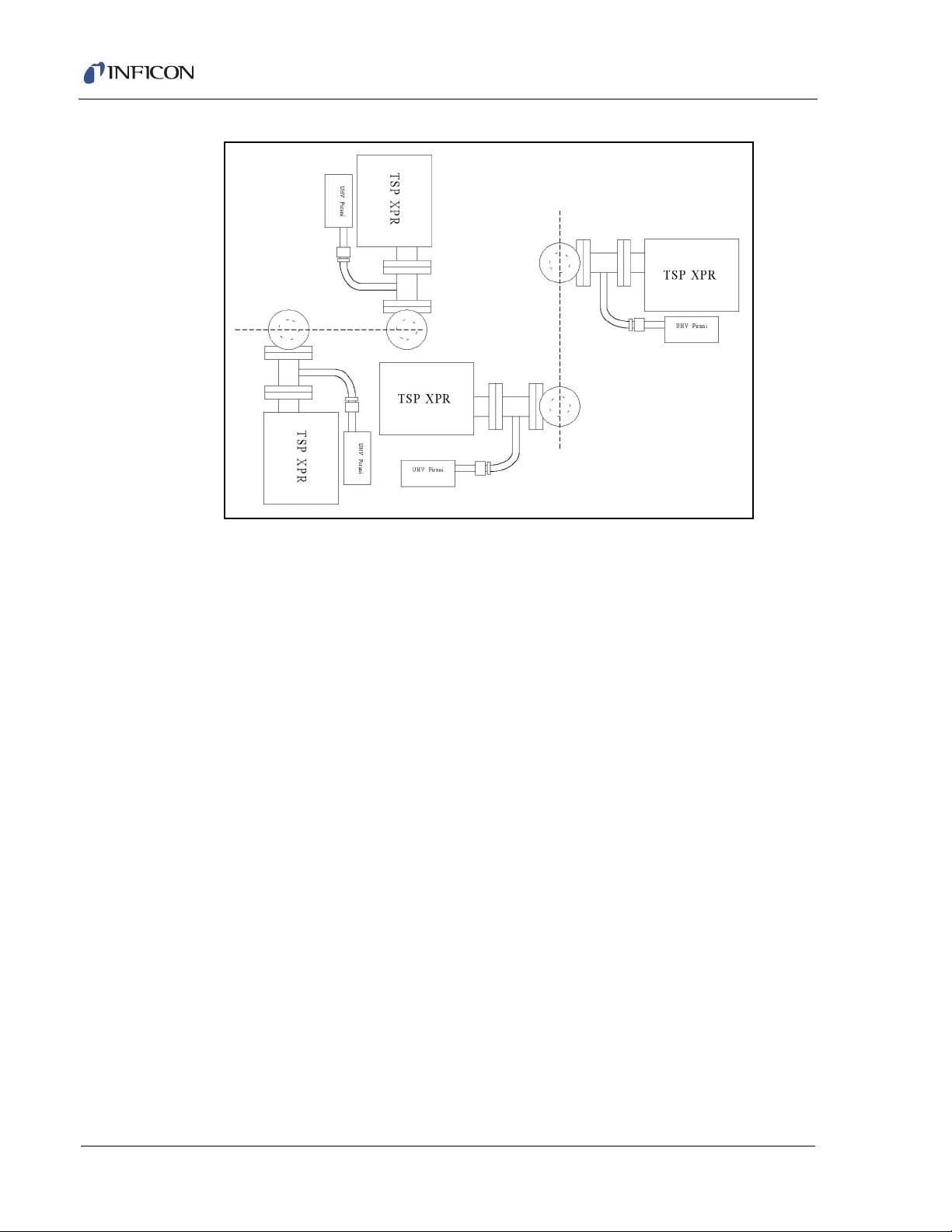
Transpector XPR 3+ Operating Manual
Figure 1-17 Orientations for mounting an Transpector XPR 3+ on a tool
2 Attach the Interlock Weldment Assembly to the 1½ in. Right Angle Valve with a
Cu gasket using ¼-28 x 1¼ in. 12 pt SS silver plated bolts, with the nut plates
on the Valve side. Tighten the bolts finger tight.
3 Check for orientation and alignment: the Pirani gauge tube should be oriented
so that the VCR fitting is facing away from the valve.
4 Tighten all the bolts evenly and gradually in a star pattern until the flange faces
come into contact.
1.16.4 Mounting the Pirani Gauge
The Pirani gauge is UHV compatible with a SS body, ceramic electrical
feed-through and a 8-VCR female mounting flange.
1 Connect the Pirani gauge flange to the port on the Interlock Weldment
Assembly using a Ni-8-VCR -2 silver plated Ni gasket.
2 Adjust the orientation of the Pirani gauge and tighten the gland finger tight. Use
a 1-1/16 in. open end wrench for the female nut and a 15/16 in. open end for
the male nut.
NOTE: For Ni gaskets, tighten an additional 1/8 turn (45 degrees) beyond finger
tight with the wrenches to seal the Pirani gauge fitting. Rotation of the
Pirani gauge can be inhibited by rotating the male nut and keeping the
female nut wrench fixed.
1 - 18
Page 27

1.16.5 Sensor Installation
CAUTION
Do not touch any surface on the vacuum side of the
sensor with bare fingers. If it is necessary to touch any of
these parts, always wear clean linen, nylon, powder free
latex or vinyl laboratory gloves.
Before installing the sensor on your system, check for
any signs of loose or broken parts.
Do not attempt to clean the sensor in any kind of solvent.
Cleaning the sensor requires its disassembly. If the
sensor is contaminated and needs cleaning, contact
INFICON.
Transpector XPR 3+ Operating Manual
1.16.5.1 Attaching the Sensor to the Vacuum Chamber
The sensor may be mounted in any position when attaching it to the vacuum vessel
or chamber.
1 Attach the Transpector XPR 3+ Sensor Flange to the Pirani Interlock Weldment
Assembly CF-40 Flange with a Cu gasket using ¼-28 x 1¼ in. 12pt SS silver
plated bolts, with the nut plates on the Transpector XPR 3+ side of the Flange.
Tighten the bolts finger tight.
2 Tighten all the bolts evenly and gradually in a star pattern until the flange faces
come into contact.
1 - 19
Page 28
Transpector XPR 3+ Operating Manual
CAUTION
Avoid mounting the sensor near any magnetic fields
greater than two gauss.
It is important that the connection between the sensor
and the vacuum chamber does not interfere with gas
exchange to ensure that the gas composition accurately
reflects that existing in the vacuum chamber.
If materials are evaporated or coatings are deposited in
the vacuum chamber, the sensor must be protected
against the deposition of these materials on its surfaces
by installing a baffle or deflector.
In systems which are baked, include the sensor in the
bakeout zone or provide it with separate heaters.
Dimensions of the quadrupole sensors are shown in Figure 1-18.
Figure 1-18 Sensor dimensions
1 - 20
Page 29
Transpector XPR 3+ Operating Manual
CAUTION
CAUTION
CAUTION
WARNING
The silver-plated bolts used for mounting the sensor to
the vacuum system must be oriented such that the bolt
heads are on the same side of the sensor as the
electronics box. Otherwise, there may be interference
between the black INFICON Transpector mounting nut
and sensor mounting hardware.
Maximum bakeout temperature for sensors is shown in
Table 1-1.
Table 1-1 Sensor maximum bakeout temperature
Maximum
Operating
Sensor
Transpector XPR 3+ 150°C 200°C
Temperature
Maximum Bakeout
Temperature
Electronics Removed
Transpector XPR 3+ electronics module must be
removed prior to bakeout at temperatures greater than
150°C (FC).
Do not turn on the Electron Multiplier (EM) at sensor
temperatures above 150°C. Turning on the EM at elevated
temperature could result in permanent damage to the
detector.
During or immediately after bakeout, the heating jacket
and metal surfaces in the vicinity of the heating jacket
may be extremely hot. These surfaces may exceed 100°C
at the maximum ambient operating temperature (50°C),
which will cause burns if touched directly without using
the proper personal protection equipment.
1 - 21
Page 30
1.16.6 Electronics Module Installation
121.67 mm
60.32 mm
57.48 mm
114.96 mm
(4.79 in.)
(2.375 in.)
(2.263 in.)
4.526 in.
Transpector XPR 3+ electronics module must be mounted in an area where the
ambient temperature does not exceed 50°C and there is free air circulation around
the electronics module. Best performance will be achieved if the electronics
module is not located close to major heat sources where it is subjected to wide
temperature variations. (See Figure 1-19.)
After the sensor has been installed on the vacuum system, the
Transpector XPR 3+ electronics module must be mounted on the sensor:
1 The Transpector XPR 3+ sensor mounting connector assembly includes a
mounting nut, a flat teflon ring, and an O-ring. When the mounting nut is
tightened, the O-ring compresses making a tight fit on the sensor housing. For
proper installation, place the nut over the end of the sensor and roll the O-ring
back to the groove on the sensor.
2 Note the alignment pin or key pin and match the sensor feedthrough to the
electronics module and carefully slide the Transpector XPR 3+ module onto the
sensor. Ensure the Transpector XPR 3+ electronics module slides on fully.
Transpector XPR 3+ Operating Manual
3 Hand tighten the mounting nut on the Transpector XPR 3+ sensor.
4 Continue to section 1.16.8 and install the communications cable.
Figure 1-19 Electronics module dimensions
1 - 22
Page 31

1.16.7 Initial Start-up Procedure
Ethernet Port
Once the Transpector XPR 3+ sensor, electronics, valve and Pirani are installed,
the valve should be opened to allow Transpector XPR 3+ to obtain high vacuum. It
is strongly recommended that Transpector XPR 3+ be kept under high vacuum
conditions for at least eight hours before the filament is turned on. It is also strongly
recommended that Transpector XPR 3+ be baked out with the supplied heating
jacket (which operates at 150 °C), for a period of at least eight hours. This eight
hour minimum bakeout reduces residual water vapor levels that may be higher due
to local surface outgassing effects. These recommendations should be followed
whenever the Transpector XPR 3+ sensor is exposed to atmosphere for long
periods of time and will serve to increase sensor life.
1.16.8 Installing Ethernet Communications
Communication cables are required to connect Transpector XPR 3+ to the
computer. Ethernet communication is the default communication method for
Transpector XPR 3+. Communication cables are required to connect Ethernet
communication uses standard RJ45, Cat5e Ethernet cables. To use Ethernet
communications, attach the supplied Cat5e Ethernet cable to the LAN port on the
back of the Transpector XPR 3+ electronics module. (See Figure 1-20.)
Transpector XPR 3+ Operating Manual
For networking information, see section 2.2.
Figure 1-20 Ethernet port
1 - 23
Page 32

1.16.9 Connecting the 24 V(dc) Power Supply
Auxilliary I/O
1 Connect the +24 V (dc) power supply cable to the 24V connector on the
Transpector XPR 3+ electronics module by sliding back the latch, installing the
cable, and then releasing the latch.
NOTE: The latch locks the connector to the electronics module, and must be
slid back to detach the cable from the Transpector XPR 3+ electronics
module.
2 Plug the AC line cord into the mating IEC320 connector on the power supply
module.
NOTE: The AC Line Input for the +24 V(dc) Power Supply must be rated:
90-260 V(ac), 40 W maximum, 47-63 Hz.
3 Plug the AC line cord into an appropriate AC outlet.
4 Verify that the green power indicator on the Transpector XPR 3+ back panel is
illuminated. If the green indicator is not illuminated, check the power
connections.
Transpector XPR 3+ Operating Manual
1.16.10 Connecting the Pirani Interlock Cable
The Pirani gauge is fully powered by the Transpector XPR 3+ Auxilliary I/O
connection. Install the RJ-45 connection of the interlock cable into the gauge and
connect the 15-pin D-Sub connection to the Auxilliary I/O port of
Transpector XPR 3+. See Figure 1-21.
Figure 1-21 Assembled interlock
1 - 24
Page 33

1.16.11 Attaching Heating Jackets
WARNING
Heating Jackets for the Transpector XPR 3+ Pirani Interlock Weldment and the
Isolation Valve are installed separately but share a common power cord.
The dual element heater can be operated with 120/230 V(ac) by choosing the
power cord with the appropriate power source connector. Part numbers for the
heaters and power cords are:
Dual element heater for Interlock Weldment
IPN 914-415-P1
Dual element heater for Isolation Valve
IPN 914-407-P1
Power cord for 120 V(AC) operation
IPN 600-1487-P1 and 068-0433
Power cord for 230 V(AC) operation
IPN 600-1487-P2 and 068-0434
The operating temperature of the heater is nominally 150 °C. Thermal
over-temperature protection is built into the heater.
Transpector XPR 3+ Operating Manual
During or immediately after bakeout, the heating jacket
and metal surfaces in the vicinity of the heating jacket
may be hot. These surfaces may exceed 100 °C at the
maximum ambient operating temperature (i.e., 50 °C),
which will cause burns if touched directly without using
the proper personal protection equipment.
1.17 Input/Output (I/O)
This section describes the input and output (I/O) for Transpector XPR 3+.
The Transpector XPR 3+ electronics module supports the following I/O functions
through the AUX I/O connector located on the back panel. See Figure 1-22.
1 - 25
Page 34

1.17.1 Two Digital Inputs
CAUTION
Logic Inputs 1 and 2 are by default set to remotely control emission status.
Connecting Pin 14 (Logic Input 1) to Pin 15 (Ground) will turn on the emission.
Connecting Pin 13 (Logic Input 2) to Pin 15 will turn off the emission. See Table 1-2.
Table 1-2 Digital inputs
Emission ON PIN 14
Emission OFF PIN 13
GND PIN 15
Controlling emission through the digital inputs bypasses
all software or hardware interlocks. When using digital
inputs for controlling Transpector XPR 3+ emission,
develop an interlock that will not allow the emission to
turn on if the pressure is too high for operation of
Transpector XPR 3+.
Transpector XPR 3+ Operating Manual
1.17.2 One Status Relay Output
One status relay output is active (closed) when the emission is on.
See Table 1-3.
Table 1-3 Status relay output
EMISSION ON Relay closed. PIN 2 and PIN 1connected
EMISSION OFF Relay open
CONTACT RATING 24 V(dc) at 0.5 A
1 - 26
Page 35

Transpector XPR 3+ Operating Manual
Figure 1-22 Pinout connectors
1 - 27
Page 36

1.17.3 One Analog Input
One analog input is differential and can handle inputs between 0 to +10 volts and
common mode voltages of 100 volts. See Table 1-4.
Table 1-4 Analog inputs
ANALOG INPUT 1 (+) PIN 9
ANALOG INPUT 1 (-) PIN 10
Transpector XPR 3+ Operating Manual
NOTE:
The analog input is supported through FabGuard software. If the Pirani
interlock option is configured the Pirani gauge reading will use analog
input 1.
1 - 28
Page 37

Chapter 2 Connecting Transpector XPR 3+
2.1 Introduction
Transpector XPR 3+ uses Ethernet as its default communications method.
Transpector XPR 3+ has an IP address and a MAC address.
IP addresses are used as a means of identifying individual devices on a network.
IP addresses are unique on a network but not universally, that is, meaning that only
one device on a network can have a specific IP address but two devices on
separate networks can have the same IP address.
MAC addresses are another identifier that are unique for each device. MAC
addresses are never duplicated. FabGuard uses IP addresses to locate and
identify sensors on a network.
2.2 General Networking Information
Transpector XPR 3+ Operating Manual
This section will discuss some of the general networking variables that can affect
the connection of Transpector XPR 3+.
2.2.1 IP Addresses
IP addresses can be set either manually or automatically:
Static (manual) IP addresses are set by the user and are manually changeable
by the user
Dynamic (automatic) IP addresses are automatically set by a Host
INFICON recommends using Static IP addresses for Transpector XPR 3+ but
allows for Dynamic IP addresses set through DHCP (Dynamic Host
Communication Protocol).
NOTE: When using Static IP addresses, a block of addresses should be reserved
for Static use and prohibited from being assigned by the DHCP server
(Host). This will avoid duplicate IP address conflicts from occurring.
2 - 1
Page 38

Transpector XPR 3+ Operating Manual
CAUTION
Since FabGuard uses the IP address to identify each
connected Transpector XPR 3+, the IP address must not
change during operation of Transpector XPR 3+.
Using DHCP, the host may generate a new IP address
every time Transpector XPR 3+ is taken offline and then
returns online.
DHCP may also change the IP address automatically if
there is an IP address conflict on the network.
If the Transpector XPR 3+ IP address is randomly
changed during data acquisition, FabGuard will not
automatically reconnect to the Transpector XPR 3+
sensor because it does not know the newly assigned
IP address. This will lead to loss of communication and
loss of data.
Static IP addresses do not change unless the IP address
is manually changed. Static IP addresses help protect
Transpector XPR 3+ from losing communication and
data.
Transpector XPR 3+ uses IPv4 IP addresses. IPv4 IP addresses consist of 32 bits
that are traditionally displayed in dot-decimal notation which consists of four
decimal numbers each ranging from 0 to 255 separated by dots. An example of an
IP address in dot-decimal notation would be 192.168.1.100. Each part represents
an octet. Normally, the IP address consists of a Network Prefix and a Host Protocol.
2 - 2
Page 39

2.2.2 Subnetworking
A subnetwork (or subnet) is a logically visible subdivision of an IP (Internet
Protocol) network. Splitting an IP network into multiple subnets is referred to as
subnetting. Subnetting sets the region of the IP address that will be used as a
Network Prefix for all IP addresses inside of a subnet. This is accomplished
through a subnet mask. Different types of subnet masks and their implications to
IP addresses are shown in Table 2-1.
Table 2-1 Subnetting
IP address 192.168.1.104 192.168.1.105 192.168.1.150
Subnet mask 255.255.255.0 255.255.0.0 255.255.255.192
Network prefix 192.168.1.0 192.168.0.0 192.168.1.128
Host Protocol 0.0.0.104 0.0.1.105 0.0.0.22
As seen in Table 2-1, the subnet masks determine which octets of the IP address
are used as the network prefix.
Transpector XPR 3+ Operating Manual
Example 1 Example 2 Example 3
In order for two network devices to communicate, they must be on the same
subnet. This means that they must not only be connected to the same internet
network, but must also have the same network prefix. If two devices have two
different network prefixes, this means that the two devices are on different subnets.
2.3 Transpector XPR 3+ IP Address
By default, Transpector XPR 3+ ships with an IP address of 192.168.1.100 with a
subnet mask of 255.255.0.0.
NOTE: When connecting Transpector XPR 3+ to an existing local network, there
must be a static IP address for each Transpector XPR 3+ being installed.
Contact the network administrator for IP address assignments.
2.3.1 Changing Transpector XPR 3+ IP Address
There are two different methods of changing the Transpector XPR 3+ IP address.
The first method utilizes the onboard Transpector Web UI to change the
IP address. Instructions for changing the IP address via Transpector Web UI can
be found in section 2.3.1.1.1 on page 2-5.
Alternatively, the IP address can be changed through a standalone executable as
discussed next in section 2.3.1.1 on page 2-4.
2 - 3
Page 40

Transpector XPR 3+ Operating Manual
2.3.1.1 Using the INFICON Mass Spectrometer Search Utility to Change the IP Address
The alternative method of changing the Transpector XPR 3+ IP address employs
the INFICON Mass Spectrometer Search Utility (IMSSU), a standalone executable
found on the software installation disk and the RGA Manuals CD that ships with
each Transpector XPR 3+. To use the IMSSU, locate and double-click
INFICONMassSpecSearch.exe. The program does not need to be installed to
work. Upon double-clicking, the IMSSU will display as shown in Figure 2-1.
Figure 2-1 INFICON Mass Spectrometer Search Utility
2 - 4
When the IMSSU first opens, nothing will be displayed. The IMSSU detects all
Transpector XPR 3+ installed on the network regardless of IP address. The IMSSU
will start automatically, or it can be manually started by clicking Search (Clears
List). The IMSSU will then display the:
Genus (which will display XPR 3+ for Transpector XPR 3+ sensors)
Transpector XPR 3+ Serial Number
Current IP address of Transpector XPR 3+
MAC address of Transpector XPR 3+
DHCP status of Transpector XPR 3+ (On or Off)
Description (which is user editable)
Page 41

2.3.1.1.1 IMSSU Capabilities
The IMSSU has multiple built-in functions. All of these functions are available by
right-clicking on the sensor inside of the IMSSU. The right-click menu can be seen
in Figure 2-2, and the different functions are described in the following sections.
Figure 2-2 IMSSU right-click menu
Changing Transpector XPR 3+ IP Address
To change the IP address, right-click on the sensor and select
Change IP Address. The TCP/IP Properties window will display, see Figure 2-3.
Figure 2-3 IMSSU TCP/IP Properties window
Transpector XPR 3+ Operating Manual
The TCP/IP Properties window will display:
Transpector XPR 3+ MAC Address
the current Transpector XPR 3+ IP address
a Change To text box, to enter the new Transpector XPR 3+ IP address
a selection of either DHCP On or DHCP Off
To change the IP address, type the new IP address in the Change To box and click
Apply. Transpector XPR 3+ will automatically reboot and will return online with the
new IP address.
Alternatively, the IP address can be automatically assigned to Transpector XPR 3+
by selecting DHCP On (this is not recommended).
Launching Transpector Web UI
Transpector Web UI can be launched from inside of the IMSSU.
2 - 5
Page 42

Transpector XPR 3+ Operating Manual
Find Device
Find Device On will flash the power LED so that the device can be located. The
LED will flash for up to 60 seconds and then return to the fully On state.
Find Device Off will stop the flashing if executed within 60 seconds of turning the
Find Device On.
Show Settings
Click Show Settings to open a display on the right-side of the IMSSU that will
display multiple settings of Transpector XPR 3+. This is an excellent tool for
troubleshooting. The following settings are displayed:
Serial Number
Gateway
IP Address
DHCP Status
MAC Address
Description
Subnet Mask
Name
Description
Structure Version
Name
Box Type
Port
Firmware Version
TCP/IP Source
2 - 6
Page 43

2.3.1.2 Changing the Computer IP Address
An alternative to changing the Transpector XPR 3+ IP address is to change the
host computer’s IP address to allow for communication between the host computer
and Transpector XPR 3+. To change the computer’s IP address, follow these
instructions:
2.3.1.2.1 Windows 7 Instructions
NOTE: Changing the IP address of the host computer requires administrator
rights. You will need to use an administrator account to change the
IP address.
1 Click Start to display the Start menu, then click Control Panel. Start is located
on the taskbar on the Windows 7 desktop. See Figure 2-4.
Figure 2-4 Start menu
Transpector XPR 3+ Operating Manual
2 - 7
Page 44

Transpector XPR 3+ Operating Manual
2 In the Network and Internet group. click View network status and tasks.
See Figure 2-5.
Figure 2-5 View network status and tasks
3 On the network status and tasks window, click Change adapter settings. See
Figure 2-6.
Figure 2-6 Change adapter settings
2 - 8
Page 45

Transpector XPR 3+ Operating Manual
4 If the host computer is connected to Transpector XPR 3+ through the Ethernet
port of the computer, right-click Local Area Connection and select
Properties. See Figure 2-7.
Figure 2-7 Changing adapter settings
5 Select Internet Protocol Version 4 (TCP/IPv4), then click Properties.
See Figure 2-8.
Figure 2-8 TCP/IPv4
6 In the TCP/IPv4 properties menu, select Use the following IP address.
See Figure 2-9.
Figure 2-9 Use the following IP address
2 - 9
Page 46

Transpector XPR 3+ Operating Manual
7 In IP address: type 192.168.1.XXX. The last octet can be any number as long
as it is unique to the network. See Figure 2-10.
8 In Subnet mask: type 255.255.0.0.
9 Click OK.
Figure 2-10 Changing the computer IP address
10 The IP address will now be set to the manual IP address chosen in step 7.
Exit all of the menus and then connect to Transpector XPR 3+.
11 To change the IP address back to its default settings, follow steps 1 through 6
and return the IPv4 properties to their original settings.
2.4 Connecting Transpector XPR 3+
Before connecting Transpector XPR 3+, decide:
1 Is Transpector XPR 3+ going to be set up on:
a private network (installed directly on to either a computer or a router that
is not hooked up to the internet), or
an internal network where multiple computers are connected with ac c e s s t o
the internet?
2 Is more than one Transpector XPR 3+ sensor being installed at the same time?
2 - 10
Page 47

Transpector XPR 3+ Operating Manual
CAUTION
2.4.1 Connecting a Single Transpector XPR 3+
2.4.1.1 Single Transpector XPR 3+ Direct Connection Installation
When installing a single Transpector XPR 3+ on a private network or directly
connected to a computer, changing the IP address of Transpector XPR 3+ is only
necessary if the computer being used to connect to Transpector XPR 3+ has a
different network prefix than Transpector XPR 3+.
The network prefix of Transpector XPR 3+ is 192.168.x.x. The IP address of the
host computer used to control Transpector XPR 3+ must have a subnet mask of
255.255.0.0 and a network prefix of 192.168.x.x.
If this is not the case, change the computer IP address to match the network prefix
of Transpector XPR 3+. For example, giving the computer an IP address of
192.168.1.101 will allow Transpector XPR 3+ to communicate directly with the
computer. Refer to section 2.3.1.2, Changing the Computer IP Address, on page
2-7.
2.4.1.2 Installing a Single Transpector XPR 3+ on an Existing Local Network
When installing a single Transpector XPR 3+ on an existing local network, the
default IP address of Transpector XPR 3+ may not be compatible with the network.
Transpector XPR 3+ can have either a Static IP address (recommended) or a
Dynamic IP address set by DHCP (not recommended).
Contact your network administrator for information regarding valid IP addresses
and have them assign an IP address for Transpector XPR 3+. See section 2.3.1,
Changing Transpector XPR 3+ IP Address, on page 2-3.
2.4.2 Installing Multiple Transpector XPR 3+ Sensors
Since each Transpector XPR 3+ is shipped with the same default IP address, the
IP address of each Transpector XPR 3+ must be changed one at a time so that
each sensor has a unique IP address. See section 2.3.1, Changing
Transpector XPR 3+ IP Address, on page 2-3.
Do not connect multiple Transpector XPR 3+ to a network at the same time without first changing the IP addresses. Since the IP addresses are not unique, connecting multiple units at the same time will cause IP address conflicts on the network.
2 - 11
Page 48

Transpector XPR 3+ Operating Manual
2.4.2.1 Installing Multiple Transpector XPR 3+ Directly to a Host Computer
If multiple Transpector XPR 3+ sensors are to be connected to a single host
computer and not to an existing local area network, a private local network must be
created. Transpector XPR 3+ will have to be installed on either a router or Ethernet
switch. The router or switch is then connected to the host computer through the
LAN port of the router/switch.
2.4.2.2 Installing Multiple Transpector XPR 3+ on an Existing Local Network
If multiple Transpector XPR 3+ sensors are to be connected to an existing local
network, use an Ethernet switch instead of a router.
NOTE: Routers can cause conflicts with local networks because the router will
attempt to set IP addresses for all network connected devices.
Since Transpector XPR 3+ sensors will be network connected devices, each
sensor must have an IP address assigned to it by a network administrator. After
changing each IP address manually, connect all of the sensors to the Ethernet
switch and connect the switch to the local network.
2 - 12
Page 49

Chapter 3 How The Instrument Works
3.1 Introduction
This section explains how Transpector XPR 3+ produces its measurements.
3.2 Overview
Transpector XPR 3+ Gas Analysis System is a miniature quadrupole partial
pressure analyzer which measures the partial pressures of gases in a mixture. It is
controlled by an external computer. Transpector XPR 3+ Gas Analysis System
consists of these parts: a sensor that functions only in a high-vacuum environment,
an electronics module which operates the sensor, and the software which resides
on an external computer and controls the electronics module.
Transpector XPR 3+ Operating Manual
NOTE: The high-vacuum environment means pressures below 2.6 Pascals, or
3.3 Patents
The following patents are applicable to the design and operation of
Transpector XPR 3+ system.
"Method of manufacturing a miniature quadrupole using
electrode-discharge machining" [US 5,852,270]
Abstract
A method for manufacturing a miniature quadrupole from a single blank includes
fastening four lengthwise insulating strips into parallel slots formed in the blank. A
lengthwise axial hole is cut through the blank for the guide wire used in the EDM
process. The blank is machined lengthwise into four electrodes using the EDM
process so that the electrodes are spaced apart in a width-wise direction and each
electrode is connected to an adjacent electrode by one of the insulating strips.
During the cutting, the electrodes are held in place by the insulating strips.
approximately 2x10
-2
Torr [approx. 2.6x10⁻² mbar].
3 - 1
Page 50

Transpector XPR 3+ Operating Manual
"Method for linearization of ion currents in a quadrupole mass analyzer"
[US 5,889,281]
Abstract
A method of linearizing the sensitivity of a quadrupole mass spectrometric system
to allow the sensor to more accurately report partial pressures of a gas in high
pressure areas in which the reported data is effected by a number of loss
mechanisms. According to the invention, correction factors can be applied
empirically or software in a quadrupole mass analyzer system can be equipped
with correcting software to expand the useful range of the mass spectrometer.
"Ion collector assembly" [US 6,091,068]
Abstract
An ion collector includes a Faraday Cup collector having a conductive surface
disposed substantially parallel to and spaced from the axis of an entering particle
beam containing charged and uncharged particles. A grounded plate disposed in
the path of the particle beam allows incoming uncharged particles to impinge
thereupon. Preferably, the application of a suitable potential to the conductive plate
manipulates incoming charged ions to impinge upon either the electron multiplier
or the Faraday collector. The ion collector can further include an electron multiplier
used in conjunction with the Faraday collector to allow separate modes of
operations. Application of a suitable first potential to the electron multiplier can
cause charged particles to be deflected directly to the Faraday collector in one
mode, and application of a second potential can cause deflection of charged
particles to the electron multiplier, with the effects of the uncharged particles on the
output of the detector being minimized.
3 - 2
"Apparatus of measuring total pressure and partial pressure with common
electron beam" [US Patent Application 20020153820]
Abstract
An apparatus for determining both total and partial pressures of a gas using one
common electron beam includes a partial pressure ionization region and a total
pressure ionization region separated by a grid or aperture. A filament produces a
plurality of electrons which are focused into an electron beam by a repeller and an
aperture or an anode. The interactions between the electron beam and molecules
of said gas within the partial pressure and total pressure regions produces first and
second ion streams. A focus plate is biased such that the first ion stream is directed
to an analyzer which calculates the partial pressure of the gas. An ion collector
collects the ions from the second ion stream, where the resulting reference current
is used to determine the total pressure of the gas.
Page 51

3.4 Sensor
The Transpector XPR 3+ sensor (see Figure 3-2) analyzes gases by ionizing some
of the gas molecules (in the ion source), separating the ions by mass (in the mass
filter), and measuring the quantity of ions at each mass (in the detector). The
masses, unique for each substance, identify the gas molecules from which the ions
were created. The magnitudes of these signals are used to determine the partial
pressures (amounts) of the respective gases.
The Sensor consists of three main parts:
ion source (ionizer)
quadrupole mass filter
ion detector
All of these parts are mounted on an electrical feed-through flange, which is bolted
to the vacuum chamber where the gas analysis measurements are made.
The sensor works only in a high-vacuum environment because the ions, once
created, must not collide with other gas molecules as they move through the
sensor; otherwise, they might not be detected. The miniature design of
Transpector XPR 3+ allows it to operate at pressures higher than those necessary
for traditional RGA sensors.
Transpector XPR 3+ Operating Manual
3 - 3
Page 52

Figure 3-1 Transpector XPR 3+ sensor
Electrometer
-1275 V
-50 to -500 V
Micro-Channel
Plate
Ions
Collector
Plate
Electrons
Total Pressure
Ion Chamber
Partial Pressure
Ion Chamber
Dual Filament
Y
2O3
/ Ir
Hyperbolic
Quadrupole
18mm Long
Transpector XPR 3+ Operating Manual
3 - 4
Page 53

3.4.1 The Ion Source
The Transpector XPR 3+ sensor’s ion source, optimized for detecting residual
gases in a vacuum system, has a fairly open construction that facilitates the flow of
gas molecules into the ionizing region.
The ion source of Transpector XPR 3+ operates on the same principles as the
larger ion sources of standard open ion source sensors. However,
Transpector XPR 3+ is built with a dual ion source which supplies one ion stream
to the quadrupole filter and a second ion stream to a total pressure collector. This
design allows the total pressure collector to be well isolated from other electrodes
in the ion source so that the small ion currents from the Transpector XPR 3+
source can be measured accurately.
Inside the ion source, a heated filament emits electrons, which bombard the gas
molecules, giving them an electrical charge. While this charge may be either
positive or negative, Transpector XPR 3+ detects only positive ions. Once a
molecule is charged, or ionized, electric fields can be used to manipulate it.
The filament is an iridium wire with yttrium-oxide coating. The Transpector XPR 3+
filament can be protected by the Pirani Interlock, which controls emission within
safe operating parameters.
Transpector XPR 3+ Operating Manual
The term “emission current” refers to the stream of electrons emitted by the
filament. The filament is heated with a DC current from the emission regulator
circuit, with the resulting temperature of the filament used as the means of
controlling the emission current.
The potential (voltage) on the anode is positive with respect to the potential on the
filament. The potential difference between the filament and the anode determines
the kinetic energy (usually called the electron energy) of the emitted electrons. The
electron energy in turn determines how gas molecules will ionize when struck by
the electrons.
A three-sided repeller is centered around the filament and is connected to the low
voltage side of the filament. This geometry and potential focuses the electrons
through the partial pressure region and on into the total pressure ion region as
shown in Figure 3-2. The ions formed within the cage on the anode are pulled away
by the potential on the focus lens and formed into a beam. (The focus lens is
sometimes called an extractor, since it extracts the ions from the region in which
they are created.) The focus lens also serves to focus the ion beam into the
quadrupole. To attract positive ions, the focus lens is biased negatively with respect
to the anode.
The ion beam generated in the partial pressure chamber passes through the hole
in the focus lens and is injected into the mass filter. The ion beam generated in the
total pressure chamber strikes the exit lens and is neutralized, resulting in a current
flow. The magnitude of this current is related to the pressure in the ion source, and
3 - 5
Page 54

can therefore, be used as a measure of the total pressure. When this current
CAUTION
exceeds a preset level, the voltages operating the sensor are turned off, thus
helping to protect the sensor from damage due to an over-pressure condition.
Although this over-pressure protection feature using the
internally measured total pressure is available in
Transpector XPR 3+, it is recommended to use only the
Pirani Interlock for controlling emission to the sensor.
Exposing the Transpector XPR 3+ sensor to
over-pressure or trying to turn the emission on at high
pressures exceeding the Transpector XPR 3+ operating
specifications will cause the filaments to prematurely fail.
3.4.2 The Quadrupole Mass Filter
The ions produced in the ion source are injected into the mass filter, which rejects
all ions except those of a specific mass-to-charge ratio. Most ions contain only
one unit of charge. In Transpector XPR 3+, the mass filter is a quadrupole type,
to which is applied a combination of RF and DC potentials. The RF frequency and
amplitude determine the mass, and the RF/DC ratio determines the filter
selectivity. See Figure 3-2.
Transpector XPR 3+ Operating Manual
Figure 3-2 Sensor’s Quadrupole Mass Filter
The mass filter’s four rods (hence the term “quadrupole”) are alternately charged
to direct ions of specific masses down through the center, deflecting all larger, and
smaller masses (hence the term “mass filter”).
The mass filter consists of four parallel rods, or poles, in a square array. The rods,
and the insulators in which they are mounted, form an extremely precise
mechanical assembly. The distance between the center of the square array and the
3 - 6
Page 55

Transpector XPR 3+ Operating Manual
XV 2ftcos U PZ++=
YV 2ft +cos U–PZ+=
closest rod surface is known as the quadrupole radius, with the symbol r0. Ideally,
the rod should have a hyperbolic shape (towards the center of the assembly) rather
than round. The Transpector XPR 3+ quadrupole is machined to have the
hyperbolic shape and thus has an optimum electric field for mass filtering ions.
Opposite rods are electrically connected together. The ions are directed into the
space between the poles, in a direction nominally parallel to the length of the rods.
There the ions are separated according to their mass-to-charge ratios by the lateral
forces resulting from the potentials applied to the poles.
The applied potentials consist of an RF component and a DC component. The RF
potential on one set of rods is out of phase by 180° with respect to the RF potential
on the other set of rods, but of the same amplitude. For one pair of rods, the “X”
pair, the DC potential is positive. For the other, the “Y” pair, the DC potential is of
the same magnitude but negative. The DC and RF potentials are referenced to a
“center voltage” (sometimes called the “pole zero”). The following equations
summarize the potentials applied to the rods:
[1]
[2]
where:
V is the RF amplitude,
f is the RF frequency,
t is time,
U is the DC potential,
PZ is the pole zero.
The RF component removes the low-mass ions from the beam. Ions of sufficiently
low mass have their motions remain in phase with that of the applied RF. These
ions will gain energy from the field and oscillate with increasingly large amplitudes.
Eventually, as they travel along the length of the rods, they will strike one of the
rods and be neutralized. On the other hand, high-mass ions are focused by the RF
component to an area close to the quadrupole’s long axis, the “Z” axis.
The DC component is superimposed on the RF to remove high-mass ions from the
beam. The DC field deflects the high-mass ions toward the negative poles,
opposing the focusing effects of the RF field. Eventually, these high-mass ions
strike the negative rods and are neutralized. By a suitable choice of DC-to-RF ratio,
the mass filter can be made to discriminate against both high and low-mass ions to
the desired degree.
The kinetic energy directed along the Z axis of the mass filter (usually called the ion
energy) is primarily dependent on the difference between the potential at which the
ions were formed (approximately the anode voltage), and the pole zero. The ion
energy is usually only slightly modified by the electric field (the “fringing” field)
3 - 7
Page 56

Transpector XPR 3+ Operating Manual
V 14.438M f2r
0
2
=
between the source exit aperture and the quadrupole. Imbalances in the amplitude
of the two phases of RF applied to the rod pairs, and of the DC voltages also
applied, result in a further modification of the ion energy.
The mass of the ions passed by the filter is determined by the RF amplitude, the
RF frequency, and the quadrupole radius, as shown by the following equation:
[3]
where:
V is the peak-to-peak RF amplitude in Volts,
M the mass of the ion in atomic mass units (AMU) per electron charge,
f the RF frequency in megahertz,
r
the quadrupole radius in centimeters.
0
The mass of ions transmitted (
(provided
mass ions will be made to oscillate in phase with the RF field and thus gain
sufficient energy to strike the poles. Of course, the DC voltage must also be
increased to maintain the high-mass rejection properties of the filter. A mass
spectrum can therefore be obtained by sweeping the RF amplitude, along with the
DC voltage.
The variation in the efficiency of transmission of ions through the filter with mass is
discussed in section 3.5 on page 3-10. Following that, section 3.6 on page 3-10
discusses the behavior of the filter at very low masses where the applied voltages
approach zero.
f is constant). As the RF amplitude is increased, progressively higher
3.4.3 The Ion Detector
The ion detector region of the sensor consists of the quadrupole exit lens and the
detector itself. Often, the quadrupole exit aperture is biased negatively with respect
to the anode, focusing ions that have been transmitted through the quadrupole into
the detector element. The detector can be a simple Faraday Cup (FC), an Electron
Multiplier (EM), or a combination of both. Transpector XPR 3+ is a combination of
Faraday Cup and Electron Multiplier.
M) is directly proportional to the RF amplitude
3.4.3.1 The Faraday Cup Detector
3 - 8
The Faraday Cup detector is typically a metal plate or a cup-shaped electrode, on
which the ion beam impinges. Ions strike the detector and are neutralized, thus
drawing a current from the circuitry connected to the electrode. Usually, the current
flow that results is exactly equal to the incident ion current. In the Transpector
family of instruments, the Faraday Cup is at ground potential.
Page 57

Transpector XPR 3+ Operating Manual
The sensitivity for Transpector XPR 3+ instruments operating in Faraday Cup
mode is typically > 4x10
-7
amps per Torr. The minimum detectable partial
pressures, therefore, can be as small as 1x10
3.4.3.2 The Electron Multiplier (EM) Detector
The Electron Multiplier (EM) acts as an in situ preamplifier for improved sensitivity.
Although there are several different types of EM, their operating principals are the
same. Incoming ions are accelerated into the input of the EM by a high negative
voltage. When an ion strikes the surface of the EM, one or more secondary
electrons are emitted. These electrons are accelerated to a second surface which
is at a more positive potential, where additional electrons are generated.
This process repeats itself until a pulse of electrons emerges from the output of the
EM and is collected on a Faraday Cup. The result is that as many as a million
electrons or more can be produced by each incident ion. The current from a
Faraday detector is positive (for positive ions) while an EM detector puts out a
negative signal.
The ratio of the electron output current to the incident ion current is known as the
EM gain. The gain primarily depends on the EM type, the voltage applied to the EM
input, the voltage applied across the EM, the condition of the EM, and, to a lesser
extent, the mass and chemical nature of the incident ion. In general, the EM gain
decreases as the ion mass increases.
-9
Torr in Faraday Cup mode.
The advantage of the EM Sensor is its higher sensitivity, thus making it possible to
measure lower partial pressures. A typical Transpector XPR 3+ has an FC
sensitivity of about 4x10
pressure of 1x10
-9
has a sensitivity of greater than 4x10
detectable partial pressure of 6x10
-7
amps/Torr, resulting in a minimum detectable partial
Torr. Operating in EM mode, the Transpector XPR 3+ Sensor
-3
amps/Torr, resulting in a minimum
-12
Torr.
The main disadvantage of the EM Sensor is that the EM gain is less stable and is
less precisely known for quantitative measurements.
3.4.3.3 The Transpector XPR 3+ Microchannel Plate, High Pressure Electron Multiplier
Transpector XPR 3+ uses a Microchannel plate (MCP) High Pressure Electron
Multiplier (HPEM)/Faraday Cup detector. The MCP is a small plate (approximately
1/2" (12.7 mm) square by 1/16" (1.6 mm) thick) consisting of an array of over
10,000 very small continuous dynode multipliers, each with a 0.001" (0.03 mm)
inside diameter. Refer to Figure 3-2 on page 3-6.
The main advantage of the MCP over other multiplier designs is its smaller size.
Also, the required operating voltage is lower.
The MCP does not have to be kept under a vacuum. However, because of the large
surface area, the MCP can absorb water vapor and should be protected from
exposure to high levels of moisture over extended periods.
3 - 9
Page 58

Transpector XPR 3+ Operating Manual
When the MCP is grounded, the ions exiting the quadrupole through the exit lens
are collected on the Faraday Cup. The resulting current is conducted through the
signal output to the detection amplifier. When -1275 V is applied to the front of the
MCP, and between -500 and -50 V is applied to the back of the MCP, the ions
impinge on the front side of the MCP. The resulting electron current is collected by
the same Faraday electrode.
The front of the MCP is fixed at -1275 V in the EM mode for two reasons. First, the
ion beam exiting the quadrupole can be strongly divergent, -1275 V ensures that
the entire ion beam is deflected into the MCP. Second, if the ion’s kinetic energy as
it strikes the entrance of the EM is too low, severe mass discrimination effects can
occur. The -1275 V avoids both issues.
Use the minimum MCP voltage required to obtain the necessary peak amplitudes
and/or signal-to-noise ratio—a gain of 300 is recommended. Operating at higher
voltages than necessary will result in premature aging of the Electron Multiplier,
requiring early replacement. As the MCP ages, the voltage needed to get a specific
EM gain will increase.
3.5 Scanning Characteristics
As described above, the quadrupole acts as a mass filter for a mixed beam of
ions, rejecting those of both high and low mass, while passing those of an
intermediate mass. The selectivity of the mass filter is expressed in terms of
resolution, R, which is numerically given by the ratio of the center mass, M, to the
width, M (both in AMU), of the pass band. Since the number of the ions passed
by the filter falls off gradually as the edge of the pass band is approached, the
width is defined at the point where the ion current falls to some specified fraction
(usually 1/2 or 1/10) of the maximum value. The width of the pass band is
determined by the DC-to-RF ratio.
While the quadrupole drive circuits can be designed so that R varies in any desired
manner with M, it is usually most convenient to keep M constant at a value, which
ensures adequate separation of masses that are 1 AMU apart. This mode of
scanning is called Constant M. As a result, R is proportional to M, and therefore
the efficiency with which ions of mass M are transmitted through the quadrupole
decreases with M. Thus, the sensitivity of the sensor decreases as M increases.
3.6 The Zero Blast
When the mass filter is tuned to very low masses, the RF and DC voltages applied
to the rods approach zero. The quadrupole then ceases to act as a filter, and a
large current of unseparated ions is detected. This current is called the “zero blast."
3 - 10
Page 59

The zero blast, present in all quadrupole-based sensors, can interfere with the
K
P
----=
observation of masses 1 and 2 when significant quantities of higher-mass ions are
present. In some instruments, the magnitude of the zero blast is concealed by
preventing the voltages from reaching zero.
3.7 High Pressure Effects
Since Transpector XPR 3+ is designed to operate at pressures in the milliTorr
range, it has some special operating features. The principal difference is that the
interaction of ions with the neutral gas molecules in the sensor cannot be
neglected.
The interaction of ions with ambient gas molecules is described by the
mean-free-path property of the gas environment. The mean-free-path is the
average distance that an ion travels before interacting with a gas molecule. The
numerical value of the mean-free-path is dependent on the type of ion, the type of
gas atmosphere and the gas pressure (i.e. the concentration of gas molecules).
Transpector XPR 3+ Operating Manual
[1]
where:
is the mean-free-path,
K is a constant depending on the ion and gas species,
P is the pressure of the gas
The mean-free-path grows proportionally shorter as the gas pressure in the
sensor increases. The effect of collisions of ions with the gas molecules is to
prevent the ions from reaching the collector and being measured. Thus the
sensor output is no longer directly proportional to the concentration of the gas
species being measured.
3 - 11
Page 60

Transpector XPR 3+ Operating Manual
n
n
0
------
X
----–
exp=
n
n
0
------P
X
K
----
–
exp=
I
0
IFP1AP+exp=
The fraction of ions that are able to travel a distance X in a gas is given as:
[2]
where:
n is the remaining number of ions after travelling distance X,
n
is the original number of ions.
0
Therefore:
[3]
That is, the fraction of ions in the beam traveling from the ion source decreases with
increasing pressure, P, and increasing length, X, of the ion path. This relationship
indicates that a high pressure sensor must be made small in order to avoid the loss
of ions.
Since the fraction of ion current that is lost is predictable, the data can be linearized
by mathematically compensating for the current loss, provided that the current
output
An additional linearization term, (1+AP), is used to compensate for the effects of
ion space charge in the ion source. Transpector XPR 3+ is equipped to make this
linearizing calculation using the total pressure reading of the ion source. The
linearization factors
for each Transpector XPR 3+ Sensor for the gas being measured and the electron
energy used. The linearized ion current (
source,
where:
I of the ion source is proportional to the partial pressure of the ion of interest.
F=X/K and A, the ionizer constant, are empirically determined
I
) is proportional to the original ions in the
0
n
, is displayed using the equation:
0
[4]
I is the measured raw ion current,
P is the Transpector XPR 3+ total pressure,
A is the ionizer constant,
F is the linearization factor.
3 - 12
Page 61

Chapter 4 Applications Guide
4.1 How to Interpret the Result
This section explains how to interpret the measurements Transpector XPR 3+
produces. It is divided into three main parts:
Section 4.1.1, Qualitative Interpretation of Mass Spectra, on page 4-1, explains
how to determine which substances are present in the gas sample being
analyzed.
Section 4.1.2, Quantitative Interpretation of Mass Spectra (Calculating Partial
Pressures), on page 4-9, shows how to estimate how much of each substance
is present.
Section 4.1.3, Additional Information for Interpreting Mass Spectra, on page
4-15, provides additional information that may help you interpret mass spectra.
Transpector XPR 3+ Operating Manual
For a discussion of how Transpector XPR 3+ produces its measurements, refer to
Chapter 3, How The Instrument Works.
4.1.1 Qualitative Interpretation of Mass Spectra
The basic graphical output of a residual gas analyzer is the mass spectrum. A mass
spectrum is a pattern of peaks on a plot of ion intensity as a function of ion
mass-to-charge ratio. Each chemical substance has a characteristic mass
spectrum. Different instruments will give slightly different spectra for the same
substance. The particular characteristics of the ionizer, mass filter, and detector,
not to mention the manner in which the sample is introduced into the mass
spectrometer, all influence the spectrum that is produced.
Rarely will a mass spectrum be obtained for a pure substance. Most of the time
(especially for residual gas analyzers), the spectrum obtained will be a composite
of the individual substances which together comprise the actual sample present.
(See Figure 4-1.)
4 - 1
Page 62

Figure 4-1 Mass spectrum
Transpector XPR 3+ Operating Manual
Figure 4-1 is an example of a mass spectrum with an arbitrarily selected number
of 170 scans. The top graph shows the data taken during the 170 scans and the
selected mass peaks. The bottom graph is a trend analysis showing the most
important masses verses time. The prominent peaks for air are mass 28 from
Nitrogen, mass 32 from Oxygen, mass 40 from Argon, and mass 18 from water
vapor.
4.1.1.1 Ionization Process
When a sufficiently energetic electron strikes a gas molecule, there are many
processes that can occur, just some of which are summarized in Table 4-1.
Table 4-1 Electron impact ionization processes
XYZ + e-
+
XYZ
+ 2e
2+
XYZ
-
-
+ 3e
XY + Z
+
XY
+ Z + 2e
+
X
+ YZ + 2e
X + YZ
XZ + Y
+
XZ
+ Y + 2e
+
+ 2e
+
+ 2e
+
+ 2e
(1)
(2)
-
-
-
-
-
-
(3)
(4)
(5)
(6)
(7)
(8)
4 - 2
Page 63

Transpector XPR 3+ Operating Manual
In all cases, the reactants are a high energy electron, e-, and a gas molecule, XYZ.
The products of the first reaction are the molecule with a single electron removed
(the so-called parent ion) and two low energy electrons. In the second reaction, two
electrons are removed from the gas molecule, resulting a doubly charged ion.
Triply (or even more highly) charged ions are also possible, provided the incident
electron has enough energy.
Reactions 3 through 8 are all examples where the original molecule is broken into
fragments, at least one of which is positively charged (negative ions can also be
produced in this manner). Only the positive ion fragments are observed; the neutral
(i.e., uncharged) fragments are not detected. The mass spectrum obtained when
the parent molecule breaks apart under electron impact is commonly referred to as
the fragmentation pattern (or, sometimes, the cracking pattern). For example, a
fragmentation pattern for Nitrogen shows
14N15N+
(29 AMU).
14N+
(14 AMU), 14N
+
(28 AMU), and
2
In general, peaks from multiply charged species will be less intense than those for
the corresponding singly charged ion. For example, the doubly charged peak for
argon is typically less than one fifth as intense as the singly charged peak (it should
be noted that this intensity ratio is sensitive to the incident electron energy).
There are some situations when it is difficult to determine whether the ion is singly
or multiply charged. When a molecule is composed of two atoms of the same
element the typical partial pressure analyzer cannot distinguish between the singly
charged one-atom fragment ion and the doubly charged two-atom molecular ion,
which will both have the same mass-to-charge ratio. Refer to Figure 4-2 on page
4-6; the peak at 28 AMU is the parent ion, N
spectrum if the peak at 14 AMU is from N
+
. It is not discernible from this
2
or N
2+
. It has been demonstrated, by
2
+
other means, that the 14 AMU peak in the nitrogen spectrum is from the singly
charged fragment ion.
Most ions (with the important exception of complex hydrocarbons) have masses
very close to integer values. When the mass of an ion is not evenly divisible by the
number of charges on it, the mass-to-charge ratio will not be an integer. Thus, Ar
2+
will appear at 13.33 AMU, while F
will show up at 9.5 AMU.
3+
4 - 3
Page 64

4.1.1.2 Isotope Ratios
An additional cause of multiple peaks in the mass spectrum of a pure substance is
that most (but not all) elements are composed of more than one isotope. For
example, 99.63% of all nitrogen atoms in nature have a mass of 14 AMU; only
0.37% have a mass of 15 AMU. Carefully examine the nitrogen spectrum in Figure
4-2 on page 4-6. The largest peak at 28 AMU is the parent ion, N
29 AMU is the isotope peak,
the parent peak since there are two nitrogen atoms in the ion, each one of which
has a 0.37% chance of being 15 AMU.
Some elements have many intense isotopes (e.g., xenon is 0.096% mass 124,
0.090% mass 126, 1.92% mass 128, 26.44% mass 129, 4.08% mass 130, 21.18%
mass 131, 26.89% mass 132, 10.44% mass 134, and 8.87% mass 136.
Isotope ratios, like fragmentation patterns, are a very useful aid in recognizing
specific materials. Under normal partial pressure analyzer ionization conditions,
the peak height ratios for the various isotopes of an element will be the same as
the ratios of their natural abundance’s. That is, the probability of ionizing, for
example, the mass 35 isotope of chlorine (
ionizing the mass 37 isotope (
from HCl will be 3.07 to 1 (75.4% / 24.6%).
Transpector XPR 3+ Operating Manual
+
. The peak at
14N15N+
37
, and is 0.74% (two times 0.37%) as high as
35
Cl) is the same as the probability of
Cl). Thus, the peak height ratio of mass 35 to 37
2
For a listing of the isotopic ratios for the lighter elements, see Table 4-2. For a
complete listing of the natural abundances for the isotopes of all the elements, see
the Handbook of Chemistry and Physics from CRC Press.
4 - 4
Page 65

.
Table 4-2 Isotope ratios
Isotope Ratios
Relative
Element Mass No.
Abundance
H1 99.985
20.015
He 3 0.00013
4 ~100.0
B 10 19.78
11 80.22
C12 98.892
13 1.108
N 14 99.63
15 0.37
O16 99.759
17 0.0374
18 0.2039
F19 100.0
Ne 20 90.92
21 0.257
22 8.82
Na 23 100.0
Al 27 100.0
Si 28 92.27
29 4.68
30 3.05
P31 100.0
S 32 95.06
33 0.74
34 4.18
36 0.016
Cl 35 75.4
37 24.6
Ar 36 0.337
38 0.063
40 99.600
Transpector XPR 3+ Operating Manual
4 - 5
Page 66

4.1.1.3 Electron Energy Effects
As was previously mentioned, the exact fragmentation pattern observed will
depend on the energy of the bombarding electrons. Figure 4-2 (from a paper by W.
Bleakney, Physical Review, 36, p. 1303, published in 1930) graphs the number of
argon ions (of different charge states) produced per incident electron per Torr of
gas pressure as a function of electron energy.
Figure 4-2 Electron energy effects
Transpector XPR 3+ Operating Manual
This graph shows the number of argon ions, N, formed per electron per Torr at
0 °C versus electron energy.
The appearance potential (i.e., the minimum electron energy required to produce
a specific ion) for Ar
+
is 15.7 eV. The number of argon ions produced rises steeply
with energy until a maximum is reached at about 55 eV. As the electron energy
rises above this level, the rate of Ar
The appearance potential for Ar
+
production slowly decreases.
2+
is 43.5 eV, and the ion production rate does not
maximize until the electron energy exceeds 100 eV. The appearance potential for
3+
Ar
is approximately 85 eV, while the appearance potential for Ar4+ is over 200 eV.
Transpector XPR 3+ normally is set for 40 eV (Low Emission) setting to produce
+
Ar
ions. The low electron energy (40 eV) model of Transpector XPR 3+ operation
suppresses production of
being principally a measure of H
36Ar2+
ions at mass 18, resulting in the mass 18 current
0.
2
4 - 6
Page 67

4.1.1.4 A Qualitative Interpretation Guide
To use a partial pressure analyzer to identify unknown substances, you must
recognize three characteristics: fragmentation patterns, multiply charged ions, and
isotope ratios. Simple spectra are, in general, relatively easy to interpret and will
yield useful identifications. The analysis of complicated mixtures of substances is
much more difficult.
Table 4-3 is intended as a spectrum interpretation guide which may be of use when
first examining an unknown spectrum. The guide lists the masses of peaks,
possible ion identities for each of these masses, and common sources for each of
these ions.
NOTE: This list is by no means all-inclusive.
Table 4-3 Spectrum Interpretation Guide
Spectrum Interpretation Guide
AMU # Chemical Symbol Sources
1 H Water F or Hydrogen F
Transpector XPR 3+ Operating Manual
2H
3 HD,
, D Hydrogen, Deuterium (2H)
2
3
H Hydrogen-Deuterium, Tritium (3H)
4 He Helium
5 No known elements
12
6 C Doubly Ionized
14
7N DI
8O DI
N (Rare)
16
O (Rare)
C (Rare)
9 No known elements
10 Ne,
10
BDI
11 Ne, 11BDI
20
Ne (Rare), BF3, BCl
22
Ne (Rare), 11BF3, BCl
3
3
12 C Carbon, Carbon Monoxide F, Carbon Dioxide F
13 CH,
14 N, CH
15 CH
16 O, CH
13
C Methane F, Carbon Isotope
2
3
, NH
4
2
Nitrogen, Methane F or Note 1
Methane F or Note 1
Oxygen or Carbon Monoxide F, Ammonia
17 OH, NH
18 H
O Water
2
3
Water F, Ammonia F
19 F Fluorine or Freon F
20 Ar
2+
, Ne, HF Argon Dl, Neon, Hydrofluoric Acid
4 - 7
Page 68

Transpector XPR 3+ Operating Manual
Table 4-3 Spectrum Interpretation Guide (continued)
Spectrum Interpretation Guide
AMU # Chemical Symbol Sources
21
22
22
Ne, CO
2
Neon, DI CO
2
23
24 C
25 C
26 C
27 C
28 N
29 CH
30 C
2
H See Note 1
2
2H2
2H3
, CO, C2H4, Si Nitrogen, Carbon Monoxide, Ethylene P, Silicon
2
3CH2
2H6
31 P, CH
32 O
, S Oxygen, Sulfur, Methanol P
2
CN See Note 1, Hydrogen Cyanide F
, Al, HCN See Note 1, Aluminum, Hydrogen Cyanide
, NO Ethane P, Nitric Oxide
OH, Oxygen, Methanol F,
2
See Note 1
Ethane F or Ethanol F or Isopropyl Alcohol
33 HS Hydrogen Sulfide F
34 H
S, 34S, O
2
2
Hydrogen Sulfide P, Sulfur Isotope,
Oxygen Isotope
35 Cl Chlorine Isotope, See Note 2
36 HCl,
37
38
36
Ar, C
3
37
Cl, C3H Chlorine Isotope, See Note 2, Hydrocarbons
37
HCl, C3H
2
Hydrochloric Acid, Argon Isotope, Hydrocarbons
Hydrochloric Acid or See Note 2, Hydrocarbons
4 - 8
39 C
3H3
40 Ar, C
41 C
42 C
43 C
44 CO
45 CH
46 CH
47 C
48 HC
3H5
3H6
3H7
2
3CH2
3CH2
35
35
See Note 3, Hydrocarbons
3H4
Argon, See Note 1, Hydrocarbons
See Note 1, Hydrocarbons
See Note 1, Hydrocarbons
, CH3CO Note 1, Acetone F or Methyl Ethyl Ketone F
, C3H
8
Carbon Dioxide, See Note 3
O Ethanol F or Isopropyl Alcohol F
OH Ethanol P
Cl See Note 2
Cl, SO See Note 2, Sulfur Dioxide F
Page 69

Table 4-3 Spectrum Interpretation Guide (continued)
PP
a
K
abIab
=
PP
a
M
ab
AbIab=
Spectrum Interpretation Guide
AMU # Chemical Symbol Sources
49 C37Cl See Note 2
50 C
NOTES: (1) Fragments of several hydrocarbons, such as mechanical pump oil,
37
Cl, CF2, C4H
diffusion pump oil, vacuum grease, cutting oil, and organic solvents.
(2) Fragments of several chlorinated hydrocarbons, such as carbon
tetrachloride, tichloroethylene, and many freons.
(3) Fragments from both straight chain hydrocarbons and benzene ring
hydrocarbons.
(4) F = Fragment ion; P = Parent ion; DI = Doubly ionized
See Note 2, Freon F, Note 3
2
4.1.2 Quantitative Interpretation of Mass Spectra (Calculating Partial Pressures)
Partial pressure is defined as the pressure of a designated component in a gas
mixture. By Dalton’s Law, the sum of all the partial pressures is the total pressure.
The partial pressure analyzer is designed so that the height of a peak in a mass
spectrum is proportional to the number of ions giving rise to that peak. Also by
design, the number of ions is more or less proportional to the partial pressure of the
substance giving rise to that peak (over some specified operating pressure range).
Therefore, the height of a peak is proportional to the partial pressure of the
substance giving rise to that peak.
Transpector XPR 3+ Operating Manual
The following equation shows the relationship between the partial pressure of
substance determined by measuring the ion current at mass b:
[1]
The partial pressure of substance a is symbolized by PP
proportionality constant for the peak at mass b from substance a, and I
, while Kab is the
a
ab
is the ion
current at mass b from substance a.
The proportionality constant, K
, depends on the nature of the substance being
ab
detected and on the characteristics of the partial pressure analyzer. The
substance-dependent part is called the material factor, M
instrument-dependent part is called the analyzer factor, A
. The
ab
, and depends primarily
b
on the ion mass, b. Therefore, the original equation [1] can therefore be rewritten
as follows:
[2]
4 - 9
Page 70

Transpector XPR 3+ Operating Manual
M
ab
1
FF
ab
XF
a
------------------------------=
The material factor, Mab, depends on the fragmentation pattern for the particular
substance, the fragmentation pattern for a reference gas (usually nitrogen), and the
ease with which the substance can be ionized relative to the same reference gas.
The relationship involved is shown in equation [3]:
[3]
The term FF
the fraction of the total current of all ions from substance a which have a mass b.
Finally, XF
XF
=1). That is, it is the ratio of total ion current (for all masses) from substance
N
a to the total ion current from nitrogen, both measured at the same true partial
pressure. Both fragmentation factors and ionization probabilities depend strongly
on the energy of the ionizing electrons. If the correct values of these factors are
not known for the exact conditions of the particular analyzer being used, they can
be approximated using published values for other conditions with, generally, only
a small loss in accuracy.
Fragmentation factors can be calculated from fragmentation patterns given in the
general references cited in Chapter 9. Other valuable references include the Index
of Mass Spectral Data from ASTM, and EPA/NIH Mass Spectral Data Base by
Heller and Milne and an extensive library of spectra is available from the National
Institute of Standards and Technology (formerly the National Bureau of Standards).
Table 4-4 lists the fragmentation factors (FF) for the major peaks for selected
substances.
NOTE: Actual fragmentation factors vary significantly depending especially on the
is the fragmentation factor for substance a at mass b. It is equal to
ab
is the ionization probability of substance a, relative to nitrogen (i.e.,
a
ionizer, electron energy, and mass filter turning. For best accuracy,
measure fragmentation factors with the same instrument used for the
analysis, under the same tuning conditions.
4 - 10
Page 71

Transpector XPR 3+ Operating Manual
Table 4-4 Typical fragmentation factors for the major peaks of some common substances
.
Mass FF Mass FF Mass FF
Acetone (CH
CO Helium He Oxygen O
3)2
43 .63 4 1.00 32 .95
58 .23 16 .05
42 .04 Hydrogen H
2
27 .03 2 1.00 Toulene C2H5CH
91 .46
Argon Ar 92 .34
40 .83 Krypton Kr 60 .07
20 .17 84 .45 65 .05
86 .13
Benzene C
6H6
82 .10 Trichlorethylene C2HCl
78 .53 83 .10 95 .22
51 .11 130 .22
52 .11 Methane CH
4
132 .21
50 .10 16 .46 97 .14
2
3
3
15 .40 60 .13
Carbon Dioxide CO
2
14 .07
44 .70 13 .04 Water H
28 .11 18 .75
16 .06 Methanol CH
OH 17 .19
3
12 .01 31 .43 1 .05
32 .23 16 .02
Carbon Monoxide CO 29 .18
28 .91 28 .03 Xenon Xe
12 .05 132 .26
16 .03 Neon Ne 129 .26
20 .90 131 .22
Ethanol C
OH 22 .10 134 .11
2H5
31 .49 136 .09
45 .21 Nitrogen N
2
27 .09 28 1.00
29 .07 14 .12
O
2
29 .01
4 - 11
Page 72

Transpector XPR 3+ Operating Manual
Ionization probability factors can be approximated by substituting the relative ion
gauge sensitivities for various gases. Table 4-5 gives relative ion gauge
sensitivities for some common gases.
NOTE: This table lists relative ionization gauge sensitivities for selected
molecules. The data was compiled from Empirical Observations on the
Sensitivity of Hot Cathode Ionization Type Vacuum Gauges by R. L.
Summers (NASA Technical Note NASA TN D5285, published in 1969).
Similar, although more limited, lists of ionization sensitivities can be found
in the books by O’Hanlon (Chapter 8, Section 1.1) and Drinkwine and
Lichtman (Table I, page 5).
HINT: Actual ionization probabilities vary significantly depending especially on the
ionizer and the electron energy. For best accuracy, measure the relative
ionization probability using a hot cathode ionization gauge (calibrated for
nitrogen) to monitor a known pressure of the substance of interest. The
ratio of the gauge reading to the known true pressure is the relative
ionization probability. To determine the true pressure, use a gauge which is
gas species independent (for example, a capacitance manometer) or a
gauge with a known sensitivity factor (for example, a spinning rotor gauge).
4 - 12
Page 73

Table 4-5 Ionization probabilities for some common substances
Transpector XPR 3+ Operating Manual
Relative
Substance Formula
Ionization
Gauge
Substance Formula
Sensitivity
Acetone (CH
CO 3.6 Hydrogen chloride HCl 1.6
3)2
Air 1.0 Hydrogen fluoride HF 1.4
Ammonia NH
3
Argon Ar 1.2 Hydrogen sulfide H
Benzene C
Benzoic acid C
Bromine Br
Butane C
Carbon dioxide CO
Carbon disulfide CS
6H6
COOH 5.5 Lithium Li 1.9
6H5
2
4H10
2
2
1.3 Hydrogen iodide HI 3.1
S2.2
2
5.9 Krypton Kr 1.7
3.8 Methane CH
4
4.9 Methanol CH3OH 1.8
1.4 Neon Ne 0.23
4.8 Nitrogen N
2
Carbon monoxide CO 1.05 Nitric oxide NO 1.2
Carbon tetrachloride CCl
Chlorobenzene C
Chloroethane C
6H5
2H5
Chloroform CHCl
Chloromethane CH
Cyclohexane C
Deuterium D
Dichlorodifluormethane CCl
Dichloromethane CH
Dintrobenzene C
6H4
Ethane C
Ethanol C
2H5
Ethylene oxide (CH
4
Cl 7.0 Oxygen O
Cl 4.0 n-Pentane C5H
3
Cl 3.1 Phosphine PH
3
6H12
2
2F2
2Cl2
(NO2)
2
2H6
OH 3.6 Trinitrobenzene C6H3(NO2)
O 2.5 Water H2O1.0
2)2
6.0 Nitrous oxide N2O1.7
2
12
4.8 Phenol C6H5OH 6.2
3
6.4 Propane C3H
0.35 Silver perchlorate AgClO
2.7 Stannic iodide Snl
7.8 Sulfur dioxide SO
7.8 Sulfur hexafluoride SF
2.6 Toluene C6H5CH
8
4
4
2
6
3
3
Helium He 0.14 Xenon Xe 3.0
Relative
Ionization
Gauge
Sensitivity
1.6
1.0
1.0
6.0
2.6
3.7
3.6
6.7
2.1
2.3
6.8
9.0
Hexane C
Hydrogen H
6H14
2
6.6 Xylene C6H4(CH3)
0.44
2
7.8
4 - 13
Page 74

Transpector XPR 3+ Operating Manual
A
a
1
TFbDF
ab
G S
---------------------------------------------------=
PP
a
FF
N28
FF
ab
XF
ab
TF
b
DF
ab
G S
-------------------------------------------------------------------------------------------
Iab=
The analyzer factor, Ab, depends on the transmission and detection characteristics
of the analyzer, the Electron Multiplier gain (if the analyzer is so equipped), and the
basic sensitivity, as indicated in equation [4]:
[4]
Here, TF
factor is the fraction of ions at mass b which pass through the mass filter, relative
to nitrogen ions at mass 28. Nominally, the transmission factor is equal to 28
divided by the mass of the ion, b.
The detection factor, DF
Multiplier, the detection factor is a function of the mass of the ion and its chemical
nature, and is measured relative to that of a reference gas, typically nitrogen. In
general, as the mass ion increases, the Electron Multiplier detection factor
decreases.
The gain of the Electron Multiplier, G, measured at mass 28 for nitrogen, is the
Electron Multiplier output current divided by the Faraday mode output current,
under otherwise identical conditions. The multiplier gain is a strong function of the
high voltage applied.
The sensitivity of the instrument, S, is the ratio of Faraday mode ion current for a
given pressure of pure nitrogen measured at mass 28, and is typically expressed
in amps/Torr.
The overall relation between partial pressure and ion current, given in equation [5],
is quite general. The constants for this equation can be obtained from various
tables, but for the best accuracy, they should be measured for each instrument.
is the transmission factor of the mass filter at mass b. The transmission
b
, is equal to 1 for a Faraday Cup detector. For an Electron
ab
A brief discussion of each of the terms follows:
. . . . . . . . . . . . . . . . . . . . . . . . . . Partial pressure of substance a (usually in
PP
a
Torr).
. . . . . . . . . . . . . . . . . . . . . . . . . . Fragmentation factor, or fraction of total ion
FF
ab
current from substance a having mass b
(dimensionless; see Table 4-4 on page
4-11).
. . . . . . . . . . . . . . . . . . . . . . . . Fragmentation factor for N2+ ions at 28 AMU
FF
N28
from nitrogen (dimensionless; typically
around 0.9).
4 - 14
[5]
Page 75

Transpector XPR 3+ Operating Manual
XFa . . . . . . . . . . . . . . . . . . . . . . . . . . Ionization probability of substance a relative
to nitrogen; approximately the same as the
relative ion gauge sensitivity as shown in
(dimensionless).
. . . . . . . . . . . . . . . . . . . . . . . . . . Transmission factor, the fraction of total ions
TF
b
at mass b which pass through the mass filter,
relative to ions with a mass of 28 AMU;
nominally, T
. . . . . . . . . . . . . . . . . . . . . . . . . Detection factor for mass b ions from
DF
ab
= 28 / M (dimensionless).
FM
substance a, relative to nitrogen at 28 AMU;
assumed to be 1.00 for Faraday detectors,
but varies for Electron Multiplier detectors
(dimensionless).
G. . . . . . . . . . . . . . . . . . . . . . . . . . . . Electron Multiplier gain for nitrogen ions at 28
AMU (dimensionless; set equal to 1 for a
Faraday Cup detector).
S . . . . . . . . . . . . . . . . . . . . . . . . . . . . Sensitivity of instrument to nitrogen, the ion
current at 28 AMU per unit of nitrogen partial
pressure (usually in amps/Torr).
. . . . . . . . . . . . . . . . . . . . . . . . . . . Ion current of mass peak b resulting from
I
ab
substance a ( in amps ; a ss umes th at th er e a re
no other substances present which
contribute significantly to the total current at
mass peak b).
4.1.3 Additional Information for Interpreting Mass Spectra
The following paragraphs contain additional information which may be of use when
interpreting mass spectra.
4.1.3.1 Ion source Characteristics
It is important to recognize that the partial pressure analyzer (especially the ion
source) and the vacuum system configuration can both have an effect on the
relative concentrations of the gases detected. In order to minimize these effects,
it is necessary to have the right type of ionizer, the right type of filament, and the
right configuration of the vacuum system. This is particularly true when a
differential pumping arrangement is used because the pressure of the gas to be
sampled is too high for the Sensor to operate. J. O’Hanlon’s book, A User’s Guide
to Vacuum Technology, has a brief discussion (in Chapter 8, Section 2) of some
of these concerns.
4 - 15
Page 76

Transpector XPR 3+ Operating Manual
CAUTION
There are four classes of interactions between the sensor and the immediate
vacuum environment which can have a significant effect on the detected gas
composition.
First, the analyzer itself is a source of gas molecules because of outgassing from
its surfaces. Usually, the outgassing levels can be reduced by baking the analyzer
in vacuum. When operating in the ultrahigh vacuum (UHV) region, it is best to bake
the sensor overnight at the maximum permissible temperature with the electronics
removed. See the bakeout temperature specifications for the Transpector XPR 3+
sensor. A second overnight bakeout should be performed at the maximum sensor
operating temperature. (It can take more than three hours for all parts of the sensor
to reach maximum temperature during a bakeout, and more than six hours to cool
back down.)
Make sure that the Electron Multiplier high voltage is turned off for this (second) bakeout temperature, otherwise, permanent damage to the EM may result.
Second, it is possible that the opposite of outgassing can occur; that is, gas
molecules can be captured by the surfaces of the sensor. This effect is called
“pumping.” In such cases, the magnitude of the signals of the gases pumped will
be lower than is properly representative of the composition of the gas in the
vacuum chamber.
Third, reactions involving gas molecules on surfaces of the analyzer can result in
a change of composition. Gases can either be consumed by the surfaces, or
produced by the surfaces. One example of gas consumption is the reaction of
oxygen with a hot filament, particularly when tungsten filaments are used. The
typical result is an anomalously low concentration of oxygen detected. See
O’Hanlon’s book (Chapter 8, Section 2) for more information on filament materials
and their interactions with the gas being analyzed. An example of gases being
produced from surfaces is the liberation of carbon monoxide molecules from a
thorium oxide coated iridium filament by a sputtering mechanism in the presence
of significant quantities of argon. This latter mechanism makes the combination of
a pressure reduction system and an RGA Sensor unsuitable for measuring
nitrogen contamination in argon at the low parts-per-million (PPM) level from a
sputter deposition process. A special type of inlet system and ion source (often
referred to as a Closed Ion Source [CIS]) should be used for this type of application.
Fourth, there are cases where at least some of the ions detected are emitted from
surfaces in the ion source under electron bombardment, and are not generated in
the gas phase from neutral molecules. This process is known as electron
stimulated desorption (ESD), or sometimes as electron induced desorption (EID).
4 - 16
Page 77

Transpector XPR 3+ Operating Manual
When the sensor has been exposed to fluorine containing substances (such as
sulfur hexafluoride, chlorofluorocarbons, perfluorotributylamine, or
perfluorokerosene) for extended periods of time, it is not uncommon for a strong F
peak at 19 AMU to remain even after the fluorine containing substance has been
removed. When operating in the UHV region, EID/ESD of H
+
, C+, O+, and CO+
(and other ions) is not uncommon. The clue to diagnosing this problem is that the
observed fragmentation patterns do not match known gas phase patterns. See
pages five and six, and typical spectra TS2 through 5, 16, 28, and 30 of Partial
Pressure Analyzers and Analysis by Drinkwine and Lichtman for more information
on EID/ESD.
Partial pressure analyzers are also characterized by varying degrees of mass
discrimination; that is, the sensitivity of the instrument is a function of mass. Ion
sources show mass discrimination because various substances offer different
degrees of difficulty of ionization. Generally, heavy, large molecules are ionized
more readily than light, small molecules. There is a rough correlation between the
number of electrons in a molecule and its ease of ionization. Although the total ion
yield (i.e., the sum of ions of all masses) is electron energy and ionizer dependent,
a reasonable estimate for the number of ions produced (relative to some standard,
usually nitrogen) in a partial pressure analyzer is the relative ionization gauge
sensitivity.
+
4.1.3.2 Scanning Characteristics
Quadrupole mass filters can also exhibit mass discrimination characteristics
depending on how the control voltages are varied during the sweep through the
mass range. Most instruments are designed to operate with a constant peak width
(constant M) which results in a resolution which is proportional to the mass. This
characteristic provides a good degree of peak separation throughout the mass
spectrum, but results in an ion transmission efficiency (i.e., the fraction of all ions
of the selected mass entering the mass filter which are transmitted through it) that
decreases as mass increases.
The way the mass scale is “calibrated” or “tuned” (i.e., the way the peak positions
and widths are adjusted) can have a significant effect on the transmission efficiency
of the mass filter across the mass spectrum. If the adjustments are not made
properly, the ratios of peak heights across the mass range will not be correct.
4 - 17
Page 78

4.1.3.3 Fragmentation Factors
The fragmentation factor is the fraction of the total ion current contributed by ions
of the chosen mass. Only peaks contributing at least one percent to the total ion
current are included in the list. The sum of the factors for all the peaks in a mass
spectrum cannot exceed 1.00. The sum can be less than 1.00 if only some of the
peaks are listed (either there are many peaks, or some of the ions produced lie
outside the mass range of the particular instrument used).
The data presented earlier in Table 4-4 on page 4-11, Typical fragmentation factors
for the major peaks of some common substances, is compiled from more than one
source and is for illustrative purposes only. For maximum accuracy in determining
partial pressures, the fragmentation factors for the substances of interest should be
measured with the same instrument, and the same adjustments, as the samples to
be analyzed.
4.1.3.4 High Pressure Effects
As described in Section 3.7, High Pressure Effects, on page 3-11, when
approaching the high pressure limit of operation the ion current does not increase
linearly with pressure because of ion losses that are pressure dependent. The
degree of ion loss depends on the nature of the ion in question and the nature of
the total gas environment in the sensor. If conditions are sufficiently defined, i.e. the
type of major gases and the interaction with the ion of interest, it is possible to
compensate mathematically for the non-linear behavior at the high pressure end of
the range. Transpector XPR 3+ permits the user to make such a compensation
using the total pressure sensed by the ion source and an empirically determined
factor for specific gases. Even when the exact factor is not known, the
compensated results are typically more nearly accurate than the raw data.
Transpector XPR 3+ Operating Manual
4 - 18
Page 79

Transpector XPR 3+ Operating Manual
CAUTION
WARNING
Chapter 5 Transpector XPR 3+ Operation and Best Known Methods
5.1 Introduction
Once the Transpector XPR 3+ Sensor, Electronics Module, Isolation Valve, and
Pirani Interlock are installed, the isolation valve should be opened to allow
Transpector XPR 3+ to obtain high vacuum. It is strongly recommended that
Transpector XPR 3+ be kept under high vacuum conditions for at least eight hours
before the filament is turned on. It is also recommended that Transpector XPR 3+
be baked out with the supplied heating jacket (which operates at 150 °C), for a
period of at least eight hours. This eight hour minimum bakeout is required to
reduce residual water vapor levels that may be higher due to local surface
outgassing effects. These recommendations should be followed whenever
Transpector XPR 3+ Sensor is exposed to atmosphere for long periods of time and
will serve to increase sensor life.
Table 5-1 Transpector XPR 3+ Sensor maximum bakeout temperature
Maximum
Operating
Sensor
Transpector XPR 3+ 150 °C 200 °C
Do not turn on electron multiplier high voltage at sensor temperatures above 150 °C. Permanent damage to the electron multiplier could result.
During or immediately after bakeout, the heating jacket
and metal surfaces in the vicinity of the heating jacket
may be hot. These surfaces may exceed 100 °C at the
maximum ambient operating temperature (i.e., 50 °C),
which will cause burns if touched directly without using
the proper personal protection equipment.
Temperature
Maximum Bakeout
Temperature
Electronics Removed
5 - 1
Page 80

5.2 Precautions for Operation
There are some precautions that the operator should take to maintain sensor
performance and extend filament life. It is recommended that the
Transpector XPR 3+ filament emission be turned off manually, before
maintenance, to allow cooling before exposure to the vent gas. If manual shutdown
does not happen, the interlock will turn off the filament when the vent gas is
introduced.
The point of greatest risk to air exposure is after maintenance where the process
chamber has been exposed to air. Recommended operation after maintenance is
to pump down the chamber and Transpector XPR 3+ Sensor followed by a bakeout
with the Transpector XPR 3+ Sensor heater (and isolation valve heater, if present).
Following bakeout and cool down, the base pressure should be < 10
turn on of the filament.
See Chapter 7 for specific Maintenance Procedures.
5.3 Pirani Interlock Protection
Transpector XPR 3+ Operating Manual
-6
Torr for safe
Filament interlock protection for Transpector XPR 3+ allows the XPR 3+ filament
emission to operate at safe pressures (< 2x10
Emission OFF Interlock function. Protection is provided by a Pirani gauge, which
directly monitors pressure at the XPR 3+. Interlock protection turns off the XPR 3+
filament if the pressure increases above a maximum operating limit (< 2x10
and does not allow the filament to be turned on when pressures exceed this limit.
This chapter describes the interlock apparatus and its operation.
Interlock Protection:
prevents inadvertent turn on of the XPR 3+ emission at high pressures,
safely turns off the XPR 3+ filament when process pressures exceed a selected
pressure (the default / maximum value is 20 mTorr), and
(optionally) turns the XPR 3+ emission on at a different safe pressure (the
default for this option is OFF).
-2
5.4 FabGuard Control
5.4.1 Transpector XPR 3+ Configuration— I/O Tab
Transpector XPR 3+ RGAs have one analog input for bringing in data from devices
such as external pressure gauges. The I/O section configures the analog input.
Torr) by action of the Pirani
-2
Torr)
5 - 2
Page 81

Figure 5-1 RGA Configuration - External I/O tab
Transpector XPR 3+ Operating Manual
Name
In the Name box, enter a name for the analog input. (See Figure 5-2.)
Figure 5-2 Name
5 - 3
Page 82

Signal Type
In the item list, click the signal type.
Figure 5-3 Signal type
0 Volt Input
Figure 5-4 0 volt input =
Transpector XPR 3+ Operating Manual
Defines what an input of 0 volts means in user units. If the Signal Type is
INFICON Pirani, MxG, or BxG, the 0 volt input = value cannot be changed.
10 Volt Input
Figure 5-5 10 volt input
Defines what an input of 10 volts means in user units. If the Signal Type is
INFICON Pirani, MxG, or BxG, the 10 volt input = value cannot be changed.
High Trip Action
Figure 5-6 High Trip Action
5 - 4
High Trip Action is typically used to stop emission from turning on at pressures
too high for safe operation.
NOTE: High Trip Action offers protection in addition to the Total Pressure
Interlock in Transpector firmware if Emission and EM Off are selected.
Page 83

Transpector XPR 3+ Operating Manual
High Trip Level
Figure 5-7 High trip level
Defines the High Trip Level. If INFICON Pirani, MxG, or BxG option is selected
as the Signal Type, the value will be in Torr or millibar depending upon the units
selected in the Signal Type list.
Low Trip Action
Figure 5-8 Low trip action
Defines the action that occurs when the Low Trip Level is reached. Low Trip
Action is typically used to protect the sensor in case the pressure gauge fails, or
the pressure gauge cable becomes disconnected.
NOTE: Low Trip Action will act as an emission interlock when set to a pressure
value below the minimum value possible for the pressure gauge, and
Emission and EM Off are selected.
Low Trip Level
Figure 5-9 Low Trip Level
Defines the Low Trip Level. If INFICON Pirani, MxG, or BxG option is chosen as
the Signal Type, the value will be in units of Torr or millibar depending upon the
units selected in Signal Type.
Flex Trip Action
Figure 5-10 Flex Trip Action
5 - 5
Page 84

Transpector XPR 3+ Operating Manual
Defines the action that occurs when the Flex Trip Level is reached. Flex Trip
Level is typically used in FabGuard to turn the Emission and Electron Multiplier
back on after safe vacuum conditions are achieved.
NOTE: Flex Trip Action can turn the Emission or Electron Multiplier, or both, back
on during a process that cycles between base vacuum and higher
pressures.
Flex Trip Mode
Figure 5-11 Flex trip mode
Defines the Flex Trip mode.
Flex Trip Level
Figure 5-12 Flex trip level
Defines the level of the Flex Trip. If INFICON Pirani, MxG, or BxG option is chosen
as the Signal Type, the value entered here will be in units of Torr or millibar
depending upon the units selected in Signal Type.
5.5 Using Transpector XPR 3+
Once the sensor has been conditioned, by baking it out and then keeping it under
vacuum, the emission can be turned on.
5.5.1 Leak Detection
Using FabGuard Explorer, there is no recipe required for operating in Leak Mode.
Select the Leak Mode button to default to sampling Helium (mass 4) over time.
When leak checking a vacuum system that has a pressure of 1x10
the High Pressure Electron Multiplier should be used. The HPEM voltage that is
necessary is based on the level of the leak that you are searching for. Adjust the
HPEM voltage so that the Helium (Mass 4) signal can be observed, but do not
exceed an intensity of 1E-7 amps. Refer to the FabGuard Explorer Operating
Manual for complete information on Leak Detection Mode.
-5
Torr or lower,
5 - 6
Page 85

5.5.2 Recipe Generation
CAUTION
Using Transpector XPR 3+ for background monitoring or process monitoring is
accomplished by creating and running a recipe. Refer to the FabGuard Explorer
operating manual for complete information on Recipe Generation.
5.5.3 Mass Scale Tuning
Another part of preventive maintenance is checking the functional operation of
Transpector XPR 3+. This includes the mass position and mass resolution of the
instrument.
Refer to section 7.6, Mass Calibration, on page 7-9 for information on tuning
Transpector XPR 3+.
5.5.4 Transpector XPR 3+ Filament
The Transpector XPR 3+ filaments should last a minimum of 4000 hours when
following these Best Known Methods. It is strongly recommended that the filaments
be replaced after 4000 hours of operation (approximately six months of continuous
operation).
Transpector XPR 3+ Operating Manual
If the filaments are not replaced and are allowed to burn out, coating from the filament could contaminate the ion source plate and create electrical shorts preventing operation with a new set of filaments.
The yttria-coated filament (part number 914-022-G2) is field replaceable.
Replacement instructions are included in the filament kit and are also found at
Section 6.5.3 in this manual.
5.5.5 High Pressure Electron Multiplier
Since the HPEM is used at background and process pressure, the EM hours will
mirror those of the emission hours. The HPEM gain may degrade over time and it
is recommended to replace the EM when the EM voltage can no longer be adjusted
to achieve a 300 gain. It is expected that the HPEM will last greater than 1 year,
when used continuously.
5 - 7
Page 86

Transpector XPR 3+ Operating Manual
CAUTION
The HPEM degrades from monitoring high ion currents. Avoid measuring ion currents above 1E-7 Amps while operating with the HPEM on.
5 - 8
Page 87

Transpector XPR 3+ Operating Manual
CAUTION
CAUTION
Chapter 6 Transpector XPR 3+ Low Pressure EM
6.1 Introduction
This chapter provides information concerning the Transpector XPR 3+ Low
Pressure EM option. Information concerning the software is located in the
FabGuard Explorer Operating Manual or the FabGuard help files, included with
your Transpector XPR 3+ Gas Analysis System.
6.2 Transpector XPR 3+ Filament Caution
Sampling atmosphere or oxygen above 1x10⁻⁴ Torr using Transpector XPR 3+ is
not recommended. To obtain maximum useful life from the Transpector XPR 3+
filaments observe the following caution.
Attempting to turn on the emission above 10 mTorr
(20 mTorr with Pirani Interlock option) may result in
premature failure of filaments.
Utilize the Pirani Interlock option or other measures to
operate the Transpector XPR 3+ within a safe pressure range.
Failure to observe this caution will result in premature failure of filaments. Filament
replacement is not covered by warranty under these conditions.
Please read Chapter 3, How The Instrument Works, before using the Transpector
XPR 3+ filament and follow the recommendations in the Transpector XPR 3+
Operating Manual, Chapter 6, Best Known Methods.
6.3 Electron Multiplier Caution
Operating the Electron Multiplier at a total pressure
greater than 1x10
than 5x10
reduce its lifetime.
-7
Amps, will damage the Electron Multiplier and
-4
Torr, or with an output current greater
6 - 1
Page 88

Transpector XPR 3+ Operating Manual
6.4 Quick Start
To quickly put Transpector XPR 3+ Low Pressure EM Gas Analysis System to
work, perform the following tasks.
1 Check to ensure that everything has been receive.
See section 6.8, Supplied Items, on page 6-5.
2 Install the Hardware. See Chapter 1 Getting Started.
3 Install the Software. See Chapter 1 Getting Started.
4 Review the Transpector XPR 3+ Operating Manual, Chapter 5, Operation,
before using Transpector XPR 3+ Low Pressure EM.
6.5 Purpose of the Transpector XPR 3+ Low Pressure EM Option Gas Analysis System
Transpector XPR 3+ Low Pressure EM Gas Analysis System is a
quadrupole-based residual gas analyzer that operates at process pressures up to
10 mTorr (20 mTorr with the Pirani Interlock option). It has an Electron Multiplier that
can operate at pressures up to 1x10
analyzes gases by:
-4
Torr. The miniature quadrupole sensor
ionizing some of the gas molecules
separating the ions by mass
measuring the quantity of ions at each mass
The masses allow the identification of the gas molecules from which the ions were
created. The magnitudes of these signals are used to determine the partial
pressures (amounts) of the respective gases.
Transpector XPR 3+ is an important aid in the efficient use of a high-vacuum
system, detecting leaks and contaminants. It can indicate the partial pressures of
gases characteristic of processes occurring within a vacuum or other vessel, and
therefore, can be used to investigate the nature of a process or to monitor process
conditions.
6 - 2
Page 89

Transpector XPR 3+ Operating Manual
6.6 General Description of Transpector XPR 3+ Low Pressure EM
Option Gas Analysis System
Transpector XPR 3+ Low Pressure EM Gas Analysis System is comprised of:
Sensor
The sensor, which functions only in a vacuum environment with pressures below
-2
1x10
The sensor itself is comprised of three parts:
ion source (ionizer)
quadrupole mass filter
ion detector
Torr (2x10⁻² Torr with Pirani Interlock option).
Transpector XPR 3+ Low Pressure EM detector includes a continuous dynode
electron multiplier (CDEM) that can operate at a total pressure up to 1x10
The CDEM voltage range is 775 to 1,225 volts.
The sensor is mounted on an electrical feed-through flange, which is bolted to the
vacuum space where the gas analysis measurements are made.
Electronics Module
The electronics module controls the sensor. The electronics module and sensor
are matched, sold, and operated as a set. The electronics module attaches to and
is supported by the sensor.
Pirani Interlock (Optional)
The optional Pirani Interlock controls sensor emission.
Software
The software controls the electronics module.
-4
Torr.
6 - 3
Page 90

Transpector XPR 3+ Operating Manual
6.7 Specifications for Transpector XPR 3+ Low Pressure EM Option Gas Analysis System
Table 6-1 details the specifications for Transpector XPR 3+ Low Pressure EM.
Table 6-1 Transpector XPR 3+ Low Pressure EM specifications
Mass Range (amu) 1-100
Resolution
(per 1993 AVS Recommended Practice)
Mass Filter Type Quadrupole
Detector Type Faraday Cup and Electron Multiplier
Temperature Coefficient
(as FC, 1E-4 Torr of Ar)
Mass Position Stability (as FC 1E-4 Torr
of Ar, Constant Temperature)
Peak Ratio Stability (28/40) as FC Better than 2% over 24 hours
Sensitivity (nominal)
As FC at 40 eV / 200 µA Emission
As EM at 70 eV / 400 µA
Minimum Detectable Partial Pressure*
As FC at 40 eV / 200 µA
As EM at 70 eV / 400 µA
Minimum Detectable Concentration 50 ppm
Maximum Operating Pressure
With Pirani Interlock Option
Without Pirani Interlock
Linear Operation
< 1 @ 10% measured at mass
4, 20, 28 and 40
< 1% of peak height per °C
< 0.1 amu over 24 hours**
4E-7 amps/Torr
8E-3 amps/Torr
1E-9 Torr
6E-12 Torr
20 mTorr
10 mTorr
10 mTorr
6 - 4
Maximum Sensor Operating
Tempe r ature
Maximum Bakeout Temperature
(Electronics Removed)
Operating Temperature (Ambient) 5-50 °C
Power Input 20-30 V(dc), 24 V(dc) Typical, Latching,
Ethernet Communication Interface Standard: Cat5e Ethernet Cable
150 °C
200 °C
4-pin Din connector, internally isolated from
system ground
Connection
Page 91

CAUTION
Table 6-1 Transpector XPR 3+ Low Pressure EM specifications (continued)
Relay Outputs 1 relay, 24 V at 0.5 amps
Inputs 1 Analog Input, 2 Digital Inputs
NOTE: All specifications after a 30 minute warm up.
* MDPP (Minimum Detectable Partial Pressure) is calculated as the standard
deviation of the noise (minimum detectable signal) divided by the sensitivity of the
Sensor measured at a four-second dwell time.
** Peak Lock active for 24-hour mass position stability.
6.8 Supplied Items
See Chapter 12, Supplied Items for a what should be included with the
Transpector XPR 3+ system.
6.9 XPR 3+ Low Pressure EM Installation
Transpector XPR 3+ Operating Manual
See Chapter 1 Getting Started for instructions on how to install the
Transpector XPR 3+ system.
6.10 XPR 3+ Low Pressure EM Operation
For proper operation of the Transpector XPR 3+ system please refer to Chapter 5
Transpector XPR 3+ Operation.
Transpector XPR 3+ Low Pressure EM Gas Analysis System has an Electron Multiplier that can operate at pressures up to 1x10⁻⁴ Torr.
6 - 5
Page 92

Chapter 7
WARNING - Risk Of Electric Shock
Maintenance
7.1 Introduction
The Transpector XPR 3+ sensor is subject to aging in normal use and some of its
components will eventually require repair or replacement.
The Transpector XPR 3+ electronics module does not normally require repair or
maintenance.
Transpector XPR 3+ Operating Manual
Opening the Transpector XPR 3+ Electronic Module should only be done by qualified service personnel. There are no user-serviceable parts inside the Electronic Module.
INFICON provides complete maintenance service for both sensors and Electronic
Modules. Refer to section 1.3, How To Contact Customer Support, on page 1-2.
7.2 Safety Considerations
If Transpector XPR 3+ is used in a manner not specified by INFICON, protection
provided by the equipment may be impaired.
7.2.1 Toxic Material
The Transpector XPR 3+ sensor does not contain any toxic material. However, if
the Transpector XPR 3+ sensor is used in an application wherein toxic material is
used or generated, residue of the toxic material will likely be present on the surface
of the Transpector XPR 3+ sensor. Appropriate safety precautions must be taken
when handling contaminated sensors in order to assure safety of maintenance
personnel.
To return the sensor to INFICON for repair, refer to section 1.3.1, Returning
Transpector XPR 3+ to INFICON, on page 1-3.
The Transpector XPR 3+ electronics module is RoHS compliant.
7.2.2 Radiation
Transpector XPR 3+ Gas Analysis systems are not known to produce
harmful radiation.
7 - 1
Page 93

Transpector XPR 3+ Operating Manual
WARNING - Risk Of Electric Shock
CAUTION
7.2.3 Electrical Voltages
Transpector XPR 3+ does not present electrical hazards when enclosed and
grounded according to the specifications given in the installation instructions.
If the Transpector XPR 3+ electronics module is operated while open, hazardous electrical voltages may be present. Such operation should not be attempted except by qualified service personnel.
7.3 General Instructions For All Repair Procedures
Perform any servicing in a clean, well illuminated area.
Wear clean, nylon, lint free lab gloves or finger cots.
Do not touch the vacuum side of the sensor with
unprotected fingers.
Use clean tools.
7 - 2
Page 94

7.4 Maintenance Procedures
CAUTION
7.4.1 Bakeout of Quadrupole
If the symptoms in section 8.2, Symptom-Cause-Remedy Chart, on page 8-1,
suggest that the sensor is contaminated, try first to restore normal performance by
baking the sensor under a high vacuum
[1.333 x 10
the maximum bakeout temperatures.
If baking the sensor doesn’t increase the sensor performance, it may be necessary
to perform the tasks described in section 7.5.3, Filament Kit Replacement, on page
7-5.
If the procedures explained above do not solve the problem, contact INFICON.
Refer to section 1.3, How To Contact Customer Support, on page 1-2.
Table 7-1 Maximum bakeout temperatures
-3
Pa]—for several hours, preferably overnight. Table 7-1 represents
Transpector XPR 3+ Operating Manual
—at least 1 x 10
While
Operating
-5
Torr (1.333 x 10⁻⁵ mbar)
With
Electronics
Removed
Transpector XPR 3+
Electron Multiplier
Faraday Cup
Combination
EM Mode
FC Mode
When heating the sensor above 150 C, the electronics
module and the signal contact must be removed from the
sensor.
7.4.2 Spare Heating Jacket Part Numbers
INFICON offers several heating jackets to help in baking a sensor. These heating
jackets operate at a maximum temperature of 150
Heating jacket part numbers are shown in Table 11-1 on page 11-1.
150
150
C
C
C.
200
200
C
C
7 - 3
Page 95

7.5 Repair Procedures
Included in the
filament kit.
7.5.1 Tools Required
The hand tools shown in Figure 7-1.
A DMM capable of measuring 30M or above.
Figure 7-1 Tools required
Transpector XPR 3+ Operating Manual
7 - 4
Page 96

Transpector XPR 3+ Operating Manual
Key Pin
F - HV Out
G - Filament
H - Anode Lead
I - Extractor
J - RF1 Lead
Signal Contact
E - Filament
D - Total
Pressure
C - HV (EM)
NC (FC)
B - RF2 Lead
A - Ground Lead
7.5.2 How to Determine if a Filament Kit Replacement is Required
Follow these steps to determine if a filament replacement is required.
1 Measure the filament resistance. This can be accomplished while the sensor is
under vacuum by measuring the resistance between pins G and E. (See Figure
7-2.) A failed filament will measure open. An intact filament assembly will read
approximately 0.5
Figure 7-2 Transpector XPR 3+ sensor pin location
NOTE: Although the following measurements may measure below 30 M with the
filament assembly and ceramic shield in place, they must be above 30 M
when measured with the filament assembly and ceramic shield removed.
2 Measure the resistance of each of the pins with respect to ground (pin A).
These measurements should be above 30M.
3 Measure the resistance of each of the pins with respect to each other. All of
these measurements should also be above 30M, with the exception of across
the filament if the filament has not failed.
7.5.3 Filament Kit Replacement
A filament replacement kit can be purchased from INFICON. This kit contains a
new filament assembly mounted on a shipping fixture and a small Allen wrench.
Perform the following steps to replace the filament.
NOTE: Refer to section 7.5.1, Tools Required, on page 7-4, before continuing.
7 - 5
Page 97

Transpector XPR 3+ Operating Manual
CAUTION
CAUTION
Faces to
center of ion
source plate
Repeller
Do not, under any circumstances, remove the
quadrupole assembly from the ion source base plate.
Doing so will require factory realignment.
Use finger cots or talc free latex gloves when changing
the filament assembly. Do not use nylon gloves when
handling a Transpector XPR 3+ Sensor.
The Total Pressure circuit must be recalibrated after
changing the filament.
Neither the filament assembly or the ion source can be cleaned. When dirty, they must be replaced.
1 Install the filament so that the face of the repeller is parallel to the face of the
anode and the filament is approximately centered to the two mounting screws
(per steps 2 and 3 below). See Figure 7-3.
Figure 7-3 Filament assembly
2 Align the holes in the filament blocks with those on the base plate.
3 Place the lock washers on the screws, and then insert the screws through the
filament assembly and into the holes in the ion source base plate. Alternately
tighten the screws until the screw heads just touch the lock washers. See
Figure 7-4.
NOTE: Both screws must have lock washers to maintain mechanical
connection and therefore electrical connection from the traces to the
filament assembly.
7 - 6
Page 98

Figure 7-4 Filament in place on sensor
CAUTION
Face of repeller parallel to face of anode
Transpector XPR 3+ Operating Manual
4 While holding the short end of the hex wrench, alternately tighten the screws
until the hex wrench begins to flex. Alternately use a torque-limiting screwdriver
(IPN 02-389-P1 or equivalent), torque the screws to 10-12 oz In. (0.0384 Nm
to 0.0461 Nm).
Do not touch the filament wires.
7.5.4 How to Determine the Condition of the Ion Source
1 Remove the Transpector XPR 3+ sensor from the vacuum system.
2 Completely loosen the two 1-72 x 0.31 in. long gold plated cap head screws
that hold the filament assembly to the ion source plate. Remove the filament
assembly and screws. See Figure 7-5.
7 - 7
Page 99

Figure 7-5 Top view of the Transpector XPR 3+ sensor
Filament
Assembly
Screws
AnodeRepeller
Transpector XPR 3+ Operating Manual
3 Measure the resistance of each of the pins with respect to ground (refer to pin
A in Figure 7-2). These measurements should be above 30M.
4 Measure the resistance of each of the pins with respect to each other. All of
these measurements should also be above 30M.
If any of the measurements in steps 3 and 4 are less than 30M
the ion source
is contaminated and requires cleaning or replacement before the new filament
is installed. Contact the nearest INFICON Service Center for assistance with
returning the unit to the factory for repair. Refer to section 1.3, How To Contact
Customer Support, on page 1-2.
If the resistance measurements in steps 3 and 4 above are greater than
30 M
refer to section 7.5.3, Filament Kit Replacement.
7 - 8
Page 100

7.6 Mass Calibration
CAUTION
7.6.1 Mass Alignment
Transpector XPR 3+ is tuned such that it generates a known RF/DC ratio that
allows one mass to exit the quadrupole at a time. When tuning the mass scale of
Transpector XPR 3+, the RF/DC ratio is fine tuned to each tune mass.
Another part of preventive maintenance is checking the functional operation of
Transpector XPR 3+. This includes the mass position and mass resolution of the
instrument. While this mass scale tuning is accomplished in a similar fashion to
any other Transpector, Transpector XPR 3+ does have some slightly different
values for peak width adjustment.
For more detailed information reagrding mass tuning using FabGuard, please refer
to the FabGuard Explorer operating manual
7.6.1.1 Factory Tuning
The gases that are used for factory tuning of these masses are:
Hydrogen (mass 1 and 2)
Transpector XPR 3+ Operating Manual
Helium (mass 4)
Nitrogen (mass 28)
Argon (mass 40)
Krypton (mass 86)
7.6.1.2 Mass Scale Tuning at Base Pressure
Mass scale tuning can be done at base pressure using the background peaks of
water vapor (18 AMU) and nitrogen (28 AMU). The following procedure should be
used to check peak location and peak widths at mass 18 and mass 28 and to make
adjustments as needed.
Do not attempt to remove masses 1, 2, 4, or 86 AMU from the Tune Table or adjust the resolution at these masses.
7 - 9
 Loading...