

Page 1
TECHNICAL HANDBOOK
jina85e1-f (1112)
catalog no.
540-001
540-002
from software version 1.6
T-Guard™
Sensor for Leak Detection
Page 2

Printed in Germany
We reserve the right to alter the design or any data given in this handbook. This is
due to the fact that we are permanently developing ou r pr od u cts .
The illustrations are not binding. If there are divergences between your product and
the Technical Handbook, please contact us.
Reprint, translation and duplication need to be a pproved by INFICON GmbH. Please
contact your sales people for an updated version of the Technical Handbook.
INFICON GmbH
Bonner Straße 498
50968 Cologne
Germany
jina85e 0.fm Technical Handbook(1112)
2
Page 3

Content
1 Operating instructions 4
1.1 How to use this manual . . . . . . . . . . . . . . . . . . . . . . . . . . . . . . 4
1.2 Warning and danger symbols . . . . . . . . . . . . . . . . . . . . . . . . . . 4
1.3 Graphic conventions . . . . . . . . . . . . . . . . . . . . . . . . . . . . . . . . . 5
1.4 Glossary . . . . . . . . . . . . . . . . . . . . . . . . . . . . . . . . . . . . . . . . . . 5
2 Safety 7
2.1 Intended use . . . . . . . . . . . . . . . . . . . . . . . . . . . . . . . . . . . . . . . 7
2.2 Requirements to be fulfilled by the user . . . . . . . . . . . . . . . . . . 7
2.3 Restrictions of use . . . . . . . . . . . . . . . . . . . . . . . . . . . . . . . . . . 7
3 Description 9
3.1 Housing . . . . . . . . . . . . . . . . . . . . . . . . . . . . . . . . . . . . . . . . . . . 9
3.2 Interfaces . . . . . . . . . . . . . . . . . . . . . . . . . . . . . . . . . . . . . . . . 10
3.3 Vacuum diagram . . . . . . . . . . . . . . . . . . . . . . . . . . . . . . . . . . . 13
3.4 Wise Technology™ Sensor . . . . . . . . . . . . . . . . . . . . . . . . . . 19
3.5 Accessories . . . . . . . . . . . . . . . . . . . . . . . . . . . . . . . . . . . . . . 20
3.5.1 Control unit for desktop operation . . . . . . . . . . . . . . . . . . . . . . 20
3.5.2 19" control unit . . . . . . . . . . . . . . . . . . . . . . . . . . . . . . . . . . . . 23
3.5.3 Connection Cable for Control Unit, 5 m . . . . . . . . . . . . . . . . . 23
3.5.4 Connector set . . . . . . . . . . . . . . . . . . . . . . . . . . . . . . . . . . . . . 24
3.5.5 Fore Pump . . . . . . . . . . . . . . . . . . . . . . . . . . . . . . . . . . . . . . . 24
3.5.6 2m line . . . . . . . . . . . . . . . . . . . . . . . . . . . . . . . . . . . . . . . . . . 25
3.5.7 I•Stick . . . . . . . . . . . . . . . . . . . . . . . . . . . . . . . . . . . . . . . . . . . 25
3.5.8 Set of filters . . . . . . . . . . . . . . . . . . . . . . . . . . . . . . . . . . . . . . . 26
3.6 Scope of delivery . . . . . . . . . . . . . . . . . . . . . . . . . . . . . . . . . . 26
3.7 Ordering Information . . . . . . . . . . . . . . . . . . . . . . . . . . . . . . . . 27
4 Installation 29
4.1 Unpacking . . . . . . . . . . . . . . . . . . . . . . . . . . . . . . . . . . . . . . . . 29
4.2 Installing Mechanically . . . . . . . . . . . . . . . . . . . . . . . . . . . . . .29
4.3 Choosing a Fore Pump . . . . . . . . . . . . . . . . . . . . . . . . . . . . . . 30
4.4 Installing Electrically . . . . . . . . . . . . . . . . . . . . . . . . . . . . . . . . 31
4.5 Connecting the control unit . . . . . . . . . . . . . . . . . . . . . . . . . . . 31
4.6 Connecting a PLC . . . . . . . . . . . . . . . . . . . . . . . . . . . . . . . . . . 32
4.6.1 Selection of functions assigne d to the PLC inputs. . . . . . . . . . 32
4.6.2 Electrical connection of the PLC inputs . . . . . . . . . . . . . . . . . 34
4.6.3 Selection of functions assigned to the PLC outputs. . . . . . . .35
4.6.4 Electrical connection of the PLC outputs . . . . . . . . . . . . . . . . 37
T-Guard EN_jina85IVZ .fm Technical Handbook(1112)
4.6.5 Overview of all settings . . . . . . . . . . . . . . . . . . . . . . . . . . . . . . 38
4.7 Connecting a PC . . . . . . . . . . . . . . . . . . . . . . . . . . . . . . . . . . . 38
Content 1
Page 4

5 Operation 39
5.1 Running up . . . . . . . . . . . . . . . . . . . . . . . . . . . . . . . . . . . . . . .39
5.2 Calibrating . . . . . . . . . . . . . . . . . . . . . . . . . . . . . . . . . . . . . . . .41
5.2.1 Preparing Calibration . . . . . . . . . . . . . . . . . . . . . . . . . . . . . . .41
5.2.2 Start Calibration . . . . . . . . . . . . . . . . . . . . . . . . . . . . . . . . . . .42
5.3 Measuring . . . . . . . . . . . . . . . . . . . . . . . . . . . . . . . . . . . . . . . .43
5.3.1 Accumulation Mode . . . . . . . . . . . . . . . . . . . . . . . . . . . . . . . .43
5.3.1.1 Hints for a good measurement: . . . . . . . . . . . . . . . . . . . . . . . .45
5.3.2 Carrier Gas Mode . . . . . . . . . . . . . . . . . . . . . . . . . . . . . . . . . .46
5.3.2.1 Hints for a good measurement: . . . . . . . . . . . . . . . . . . . . . . . .48
5.3.3 Continuous Mode . . . . . . . . . . . . . . . . . . . . . . . . . . . . . . . . . .49
5.3.4 Switching Off . . . . . . . . . . . . . . . . . . . . . . . . . . . . . . . . . . . . . .50
5.3.5 Standby . . . . . . . . . . . . . . . . . . . . . . . . . . . . . . . . . . . . . . . . . .50
5.3.6 Helium contamination . . . . . . . . . . . . . . . . . . . . . . . . . . . . . . .50
5.4 Controlling via PLC . . . . . . . . . . . . . . . . . . . . . . . . . . . . . . . . .51
5.4.1 How to execute an accumulation measurement . . . . . . . . . . .51
5.4.2 How to execute a carrier gas measurement . . . . . . . . . . . . . .51
5.5 Controlling via RS-232 . . . . . . . . . . . . . . . . . . . . . . . . . . . . . .51
5.6 Configuring analog output . . . . . . . . . . . . . . . . . . . . . . . . . . . .52
5.7 Using the I-Stick and the parameter sets . . . . . . . . . . . . . . . .53
5.8 Settings . . . . . . . . . . . . . . . . . . . . . . . . . . . . . . . . . . . . . . . . . .54
5.8.1 Menu Structure Diagram . . . . . . . . . . . . . . . . . . . . . . . . . . . . .54
5.8.2 Explanation of Menu Items . . . . . . . . . . . . . . . . . . . . . . . . . . .56
5.9 F.A.Q. - Frequently asked questions . . . . . . . . . . . . . . . . . . .63
6 Maintenance 66
6.1 Replacing the Inlet Filters . . . . . . . . . . . . . . . . . . . . . . . . . . . .66
6.2 Replacing Hoses . . . . . . . . . . . . . . . . . . . . . . . . . . . . . . . . . . .67
6.3 Replacing the Internal Fuses . . . . . . . . . . . . . . . . . . . . . . . . .68
7 Product Handling 71
7.1 Transporting . . . . . . . . . . . . . . . . . . . . . . . . . . . . . . . . . . . . . .71
7.1.1 Transporting after Contamination . . . . . . . . . . . . . . . . . . . . . .71
7.2 Disposal . . . . . . . . . . . . . . . . . . . . . . . . . . . . . . . . . . . . . . . . . 71
8 Technical Data 72
8.1 Power supply . . . . . . . . . . . . . . . . . . . . . . . . . . . . . . . . . . . . .72
8.2 Weight / dimensions . . . . . . . . . . . . . . . . . . . . . . . . . . . . . . . .72
8.3 Characteristics . . . . . . . . . . . . . . . . . . . . . . . . . . . . . . . . . . . .72
8.4 Environmental Conditions . . . . . . . . . . . . . . . . . . . . . . . . . . . .73
8.5 Assembly Drawing for built-in Control Unit . . . . . . . . . . . . . . .73
T-Guard EN_jina85IVZ .fm Technical Handbook(1112)
2 Content
Page 5

9 Errors and Warnings 74
10 Service Centers World Wide 78
10.1 Ordering Information . . . . . . . . . . . . . . . . . . . . . . . . . . . . . . . . 80
T-Guard EN_jina85IVZ .fm Technical Handbook(1112)
Content 3
Page 6
1 Operating instructions
Warning
Caution
1.1 How to use this manual
• Please read this manual before using the T-Guard™ Leak Detection Sensor.
• Keep the manual in a way that you can use it at any time.
The INFICON T-Guard™ Leak Detection Sensor has been designed for safe and
efficient operation when used properly and in ac cord an ce with this Tec hn ica l
Handbook. It is on the user's own responsibility carefully to read and strictly to
observe all safety precautions described in this chapter and throughout this
Technical Handbook. The T-Guard™ Leak Detection Sensor must only be operated
under the conditions described in this Technical Handbook. It must be operated and
maintained by trained personnel only. Consult local, state, and national authorities
regarding specific requirements and regulations. In case you have any further
queries on safety, operation and/or maintenance, please contact our office nearest
to you.
1.2 Warning and danger symbols
Indicates procedures that must be strictly observed to prevent haza rd s to per sons.
Indicates procedures that must strictly be observed to prevent damage to, or
destruction of T-Guard™ Leak Detection Sensor.
4 Operating instructions
jina85e 1.fm Technical Handbook(1112)
Page 7

1.3 Graphic conventions
Notice Points to very useful pieces of information.
1 Points to an operation that you have to perform.
⇒ Points to the result of an operation you accomplished.
→ Points to the button you have to press.
• Shows a listing.
1.4 Glossary
Sensitivity
Characterises the ratio of the helium signal to the measured signal.
I·Stick
Optional memory extension of the T-Gu ard™ Leak Detection Sensor.
Calibration
Measuring time
Parameter set
RS232
Purge
T-Guard
Equalisation of measured signal and leakage rate.
Time from the beginning of the measurement to the output of the results.
Group of parameters, e.g. measuring time, chamber volume, carrier gas, etc.
Interface standard for data communication between electronic devices.
Removal of excessive helium from the air.
Tracer (Gas) Guard
jina85e 1.fm Technical Handbook(1112)
Operating instructions 5
Page 8

Carrier Gas
Trigger
Background
Zero
Cycle time
Large gas flow which transports a small gas flow.
Limit value of the rejection leakage rate for th e detection of le aks of the test sa mple .
The air contains 5 ppm (0.0005%) of helium by nature. For goo d measurements with
the T-Guard, the helium content in the air must be less than 10 ppm.
"Reset to Zero" is an automatic function of the T-Guard™ Leak Detection Sensor.
Time from the beginning of the measurement to the next possible measurement.
6 Operating instructions
jina85e 1.fm Technical Handbook(1112)
Page 9
2 Safety
Skilled personnel
Warning
Warning
2.1 Intended use
The T-Guard™ Leak Detection Sensor is a helium leak dete ction sensor which does
not need any vacuum chamber. It can find leaks in test samples and quantify them
when they are filled with helium under pressure.
Using the T-Guard™ Leak Detection Sensor, the chamber with the test sa mple does
not have to be evacuated.
Measured at atmospheric pressure, the minimum detectable leak rate is 1×10
l/s. This depends on the chamber volume and the measuring time, the rejection l eak
rate will mostly be between 1·10
Do not let water penetrate into the body or hoses of the T-Guard™ Leak Detection
Sensor. Do not forget to use the external filters.
Only use accessories and spare parts from INFICON.
2.2 Requirements to be fulfilled by the user
-4
and 1·10-2 mbar l/s.
-6
mbar
The T-Guard™ Leak Detection Sensor must only be started and operated by
properly trained staff.
Get used to the functioning of the device. Yo u may only use the device after reading
and understanding the manual.
2.3 Restrictions of use
Disregarding the following precautions could result in serious injury:
For all contacts of the I/O port, a maximum voltage of 60 V DC or 25 V AC must not
be exceeded or reached based on the protective cond uctor or the earthing devices.
Please refer to the information given in the following chapters.
For maintenance work, disconnect the T-Guard™ Leak Detection Se nsor from the
power supply.
jina85e 2.fm Technical Handbook(1112)
Safety 7
Page 10
Warning
Before replacing the fuses, the T-Guard™ Leak Detection Sensor must be
Caution
Caution
Caution
disconnected from the power supply.
Disregarding the following precautions could result in damage to the equipment.
The T-Guard™ Leak Detection Sensor must not be operated while standing in
water or when exposed to drip water. The same applies to all other kinds of liquid.
The T-Guard™ Leak Detection Sensor should only be used inside rooms.
Avoid the T-Guard getting in contact with bases, acids, and solvents, as well as
being exposed to extreme climatic conditions.
Do not suck up liquids into the T-Guard™.
8 Safety
jina85e 2.fm Technical Handbook(1112)
Page 11
3 Description
This chapter describes the exterior design of the T-Guar d™ Leak Detection Sensor,
its accessories and how to use it.
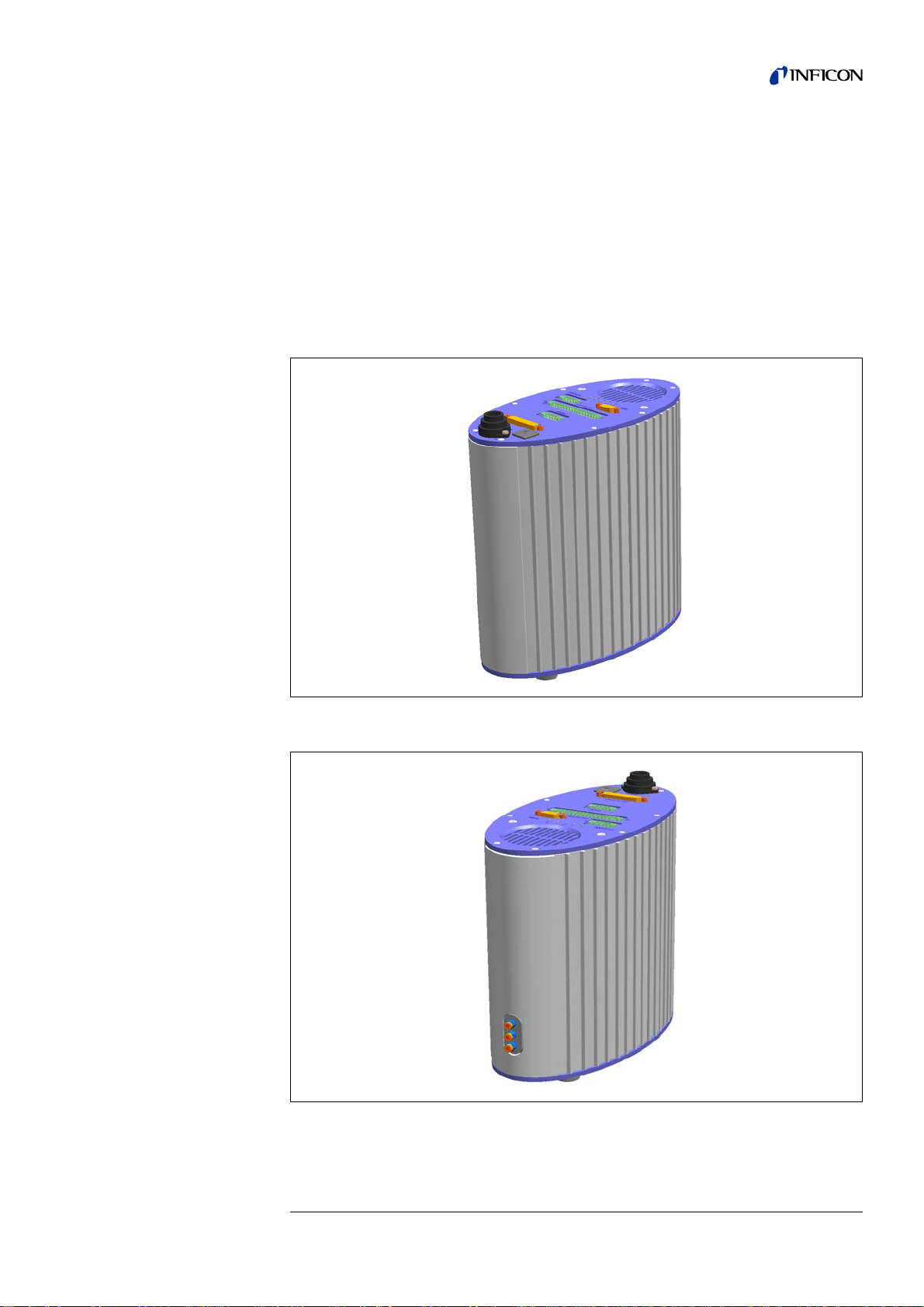
3.1 Housing
The housing of the unit consists of an oval cylinder. On top, there are several
electrical connections and the ventilation opening. On the rear side, ther e are th ree
hose connectors.
Fig. 4-1 Front view of the T-Guard™ Leak Detection Sensor
Fig. 4-2 Back view of the T-Guard™ Leak Detection Sensor
jina85e 3.fm Technical Handbook(1112)
Description 9
Page 12
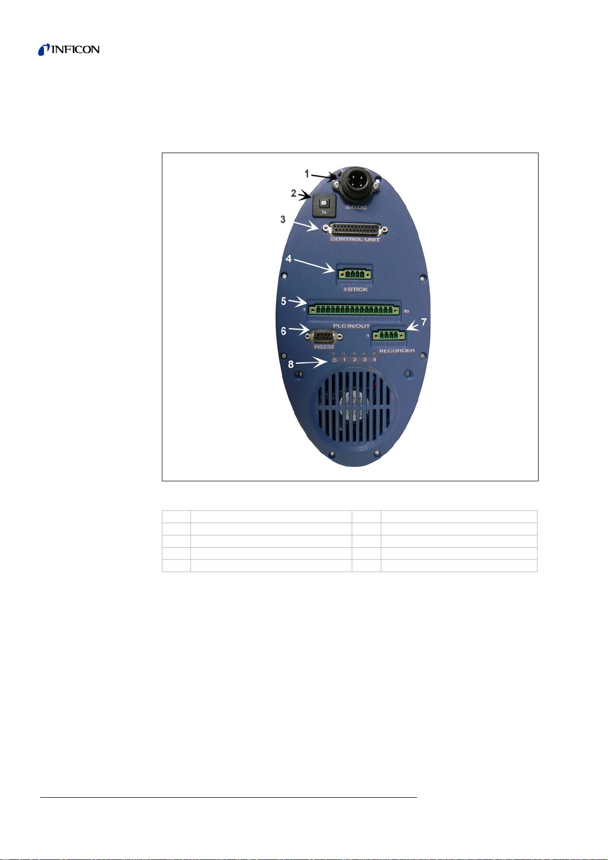
3.2 Interfaces
The T-Guard™ Leak Detection Sensor has 5 interfaces for control and information
exchange.
Fig. 4-3
Power Connector
Only two of the four pins are used for the power supply. The plus pole is marked with
„1+“, the minus pole is marked with „2-“.
Fuse
The fuse reacts to reverse polarity and a current exceeding 7 A.
Item Description Item Description
1 Power supply connector 5 PLC-interface
2 Fuse 6 RS232 PC-interface
3 Interface for the control unit 7 Analog Recorder Output
4 I•Stick -connector 8 Status LEDs
jina85e 3.fm Technical Handbook(1112)
10 Description
Page 13

Interface for the control unit
Here, the INFICON control unit (Cat. No. 551-100 or 551-101) is connected via its
connecting cable (Cat. No. 551-102 or 551-103) to control the T-Guard™ Leak
Detection Sensor manually.
Notice The connection cable must only be plugged in or unplugged when the
supply voltage of the T Guard™ is turned off or disconnected.
I•Stick -connector
You can store 25 parameter sets on the INFICON-I-Stick and also download them
from there.
PLC-interface
The T-Guard™ Leak Detection Sensor has 6 configurable digital PLC-Inputs and
8 configurable digital PLC-outputs.
(Refer to 4.6.1 Selection of functions assigned to the PLC inputs. and 4.6.3 Selection
of functions assigned to the PLC outputs..)
RS232 PC-interface
Connect any RS232 capable device here with an uncrossed RS232 cable in order to
control the T-Guard™ Leak Detection Sensor or to read out information. The latter
takes less than 100 ms.
Analog Recorder Output
The T-Guard™ Leak Detection Sensor has two separately configurable analog
recorder outputs (0 - 10 V).
They have a resolution of 16 bit and a hardware limited refresh rate of about 2 Hz.
For a higher refresh rate, please use the RS232 interface.
For detailed Information on how to use the analog output refer to chapter 5.6.
jina85e 3.fm Technical Handbook(1112)
Description 11
Page 14
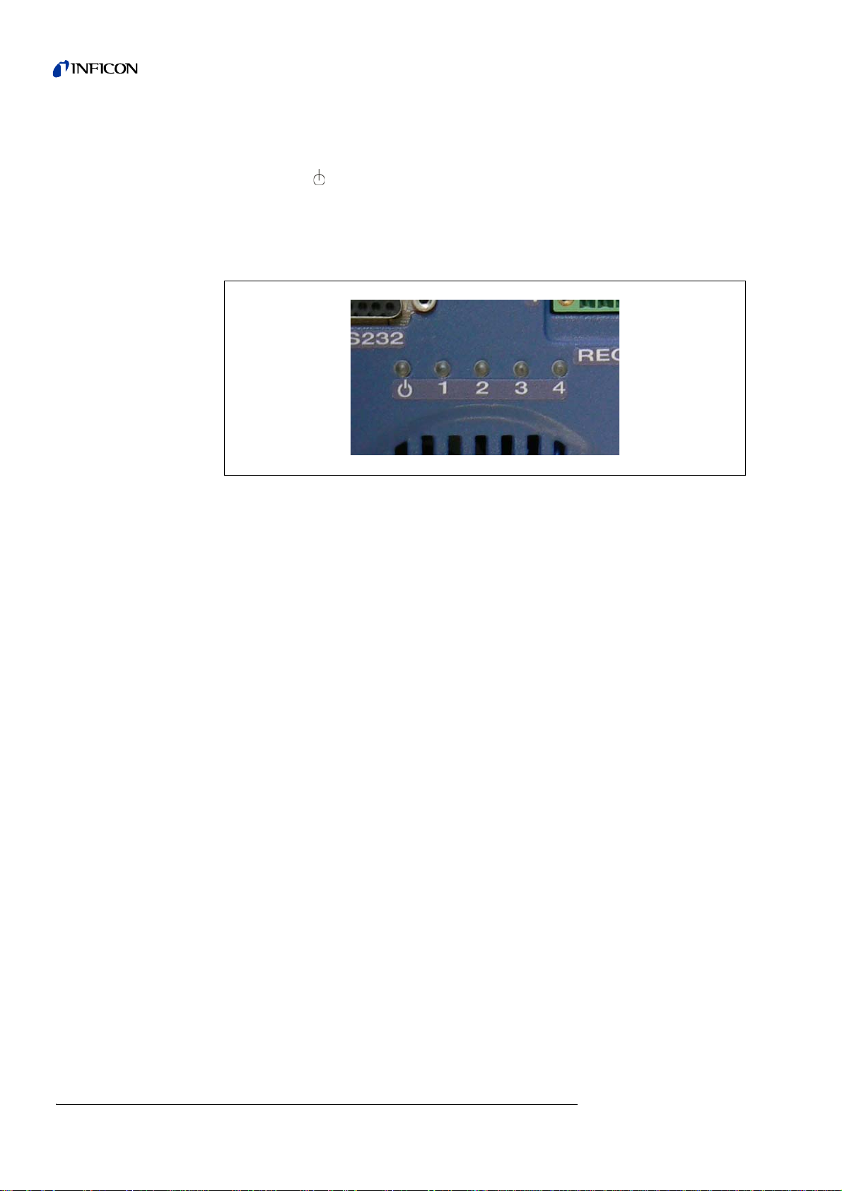
Status LEDs
Certain operating conditions can be indicated by 5 status LEDs:
The first LED : lights up during operation
The four remaining LEDsindicate the status of the configurable digital outputs 1-4.
LED No. 2 is red and in standard setting, it will light up to
indicate an error or a warning. The desired output function
can be set (refer to4.6.3).
Fig. 4-4 Status LEDs
12 Description
jina85e 3.fm Technical Handbook(1112)
Page 15
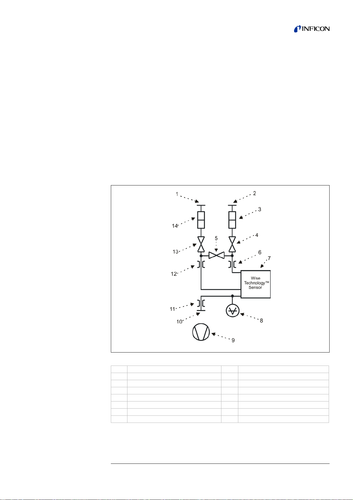
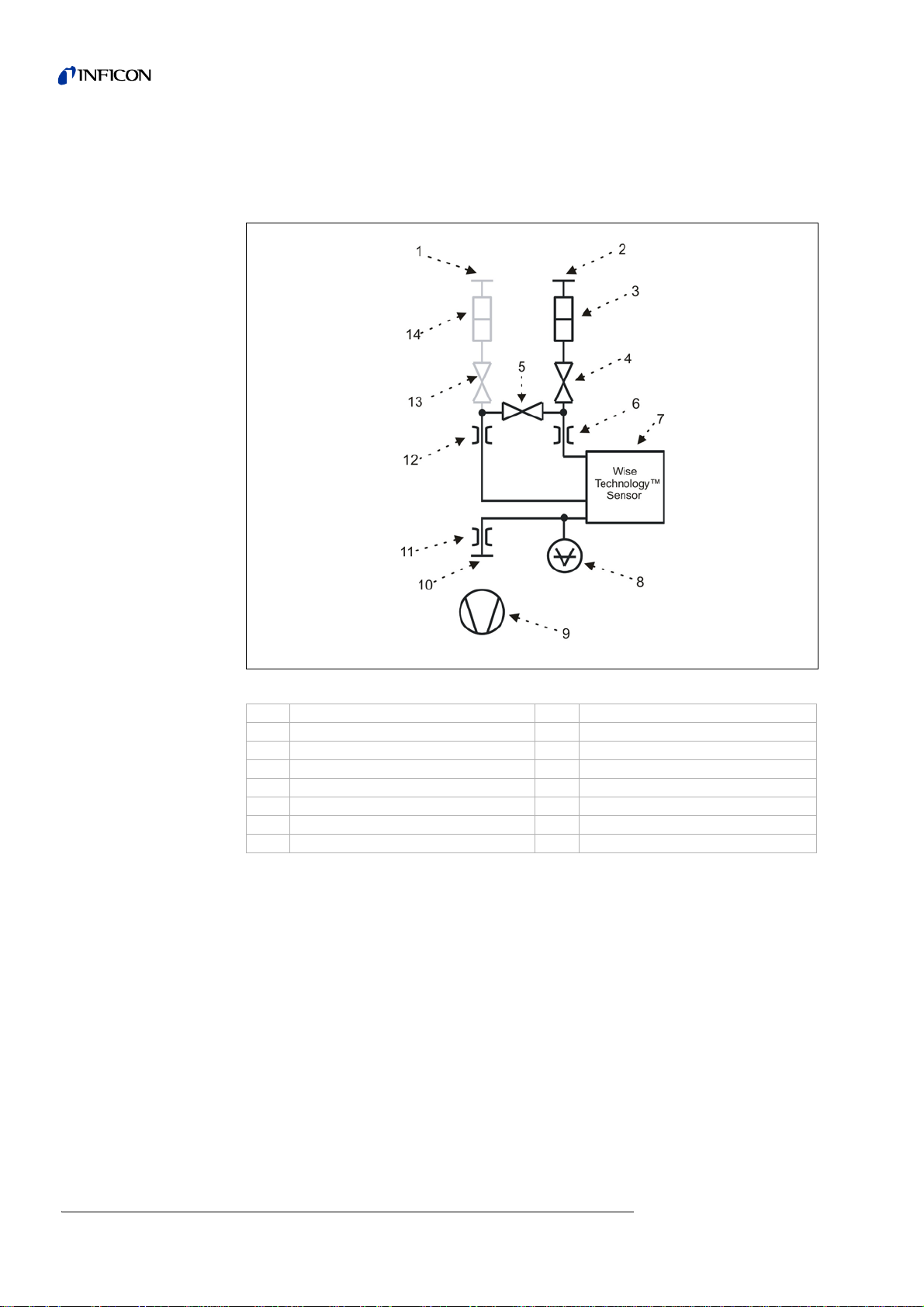
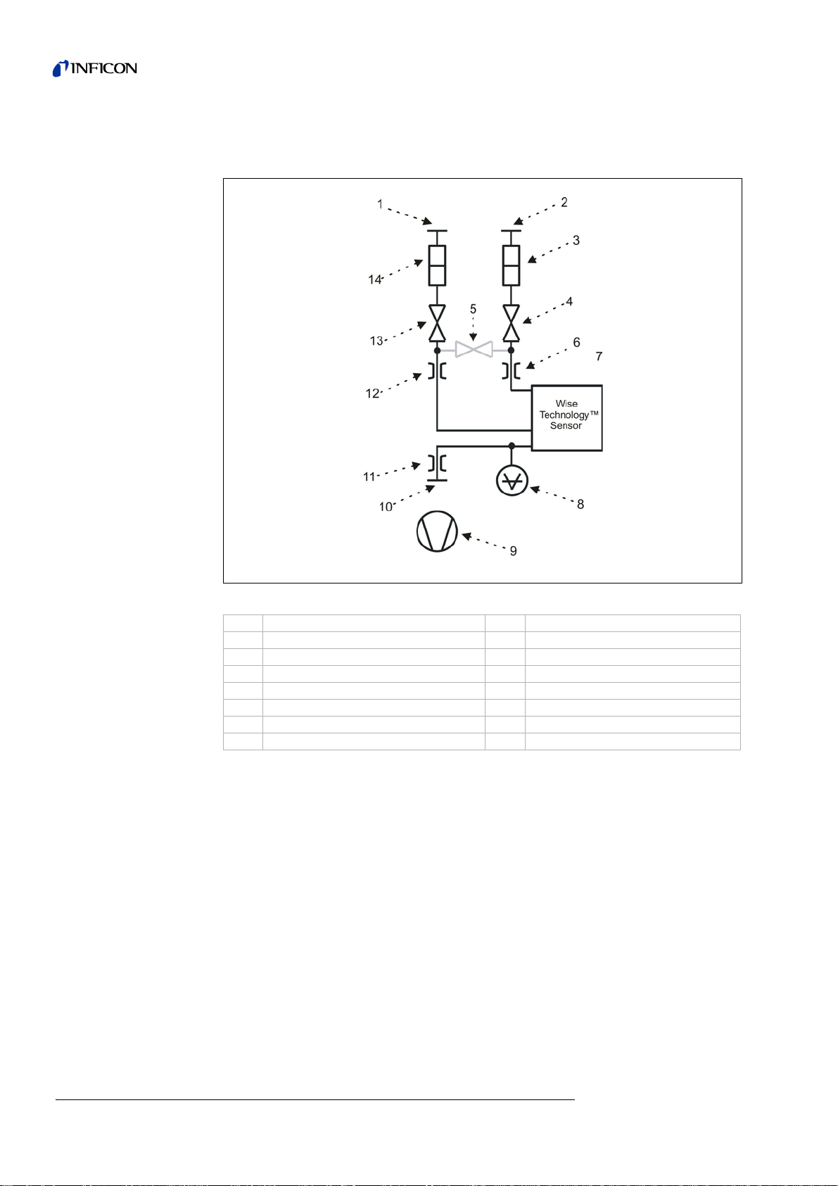
3.3 Vacuum diagram
On top of the vacuum diagram, there are the measurement inlet "IN" and the
reference inlet "Ref". Both inlets are equipped with an external filter to protect TGuard™ Leak Detection Sensor from sucking in dust or fluids. Three valves are
integrated in the T Guard™ Leak Detection Sensor (see Fig. 4-5).
Valve V1 opens and closes the measurement inlet. Valve V3 opens and closes the
reference inlet. Valve V2 opens and closes the connection between V1 and V3.
These three valves are connected to two flow-restricted capillaries which lead to the
Wise Technology™ Sensor.
The upper inlet of the Wise Technology™ Sensor is the fine inlet, the lower one is
the gross inlet, which is less sensitive to helium than the fine inlet.
The Wise Technology™ Sensor detects the heliu m in the gas stream, which passes
by. The total pressure, which is applied to the Wise Technology™ Sensor is detected
by the Pressure Gauge p1.
The fore pump, which provides the gas stream inside T-Guard™ Leak Detection
Sensor is also throttled to produce constant pressure and flow for the Wise Technology™ Sensor.
Fig. 4-5 Vacuum diagram of the T-Guard™ Leak Detection Sensor
Item Description Item Description
1 Inlet “IN” 8 Pressure gauge p1
2 Reference “Ref” 9 Pump
3 Filter 2 10 Pump connector “OUT”
4 Valve V
5 Valve V
6 Throttle 2 13 Valve V
7 Wise Technology™ Sensor 14 Filter 1
jina85e 3.fm Technical Handbook(1112)
3
2
11 Throttle 3
12 Throttle 1
1
Description 13
Page 16
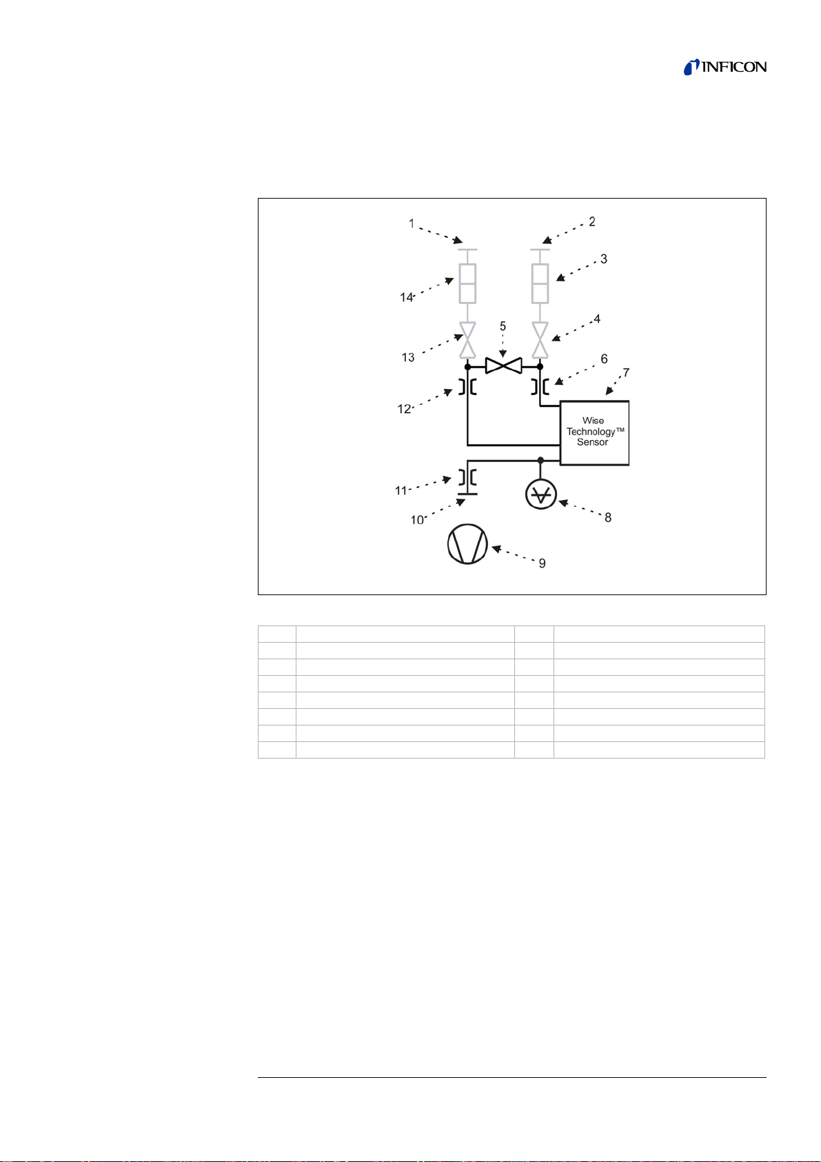
When the T-Guard™ Leak Detection Sensor is not measuring at the moment or is
READY , V2 and V3 are open, V1 is closed (refer to Fig. 4-6). Only gas from the
reference inlet gets to the sensor.
Fig. 4-6 Valve position in READY mode.
Item Description Item Description
1 Inlet “IN” 8 Pressure gauge p1
2 Reference “Ref” 9 Pump
3 Filter 2 10 Pump connector “OUT”
4 Valve V
5 Valve V
3
2
6 Throttle 2 13 Valve V
7 Wise Technology™ Sensor 14 Filter 1
11 Throttle 3
12 Throttle 1
1
14 Description
jina85e 3.fm Technical Handbook(1112)
Page 17
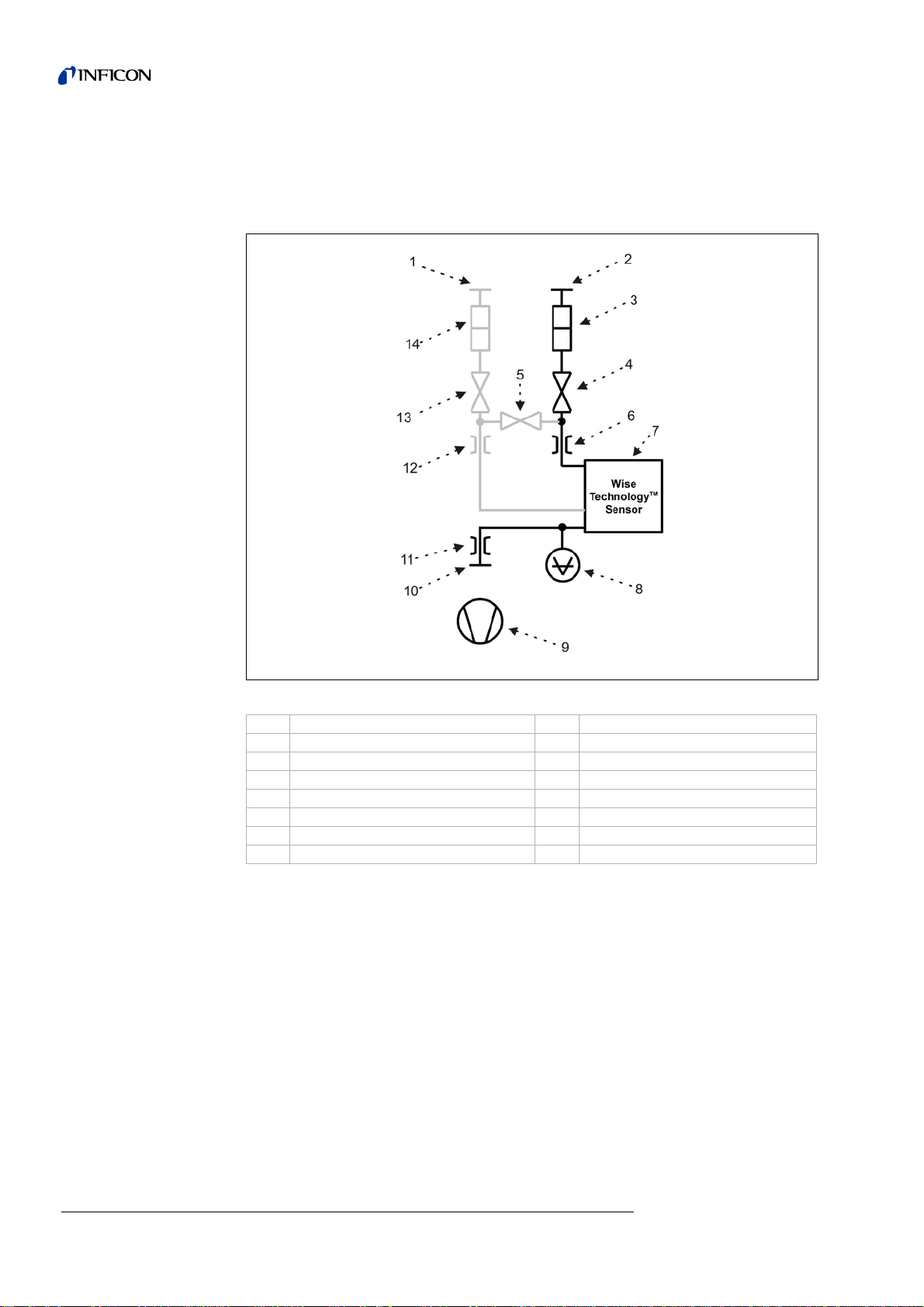
In Standby mode, all valves except V2 are closed and the pressure before the Wise
Technology™ Sensor is equal to the base pressure of the fore pump.
(refer to Fig. 4-7)
Fig. 4-7 Valve configuration in S
TANDBY mode.
Item Description Item Description
1 Inlet “IN” 8 Pressure gauge p1
2 Reference “Ref” 9 Pump
3 Filter 2 10 Pump connector “OUT”
4 Valve V
5 Valve V
3
2
6 Throttle 2 13 Valve V
11 Throttle 3
12 Throttle 1
1
7 Wise Technology™ Sensor 14 Filter 1
jina85e 3.fm Technical Handbook(1112)
Description 15
Page 18
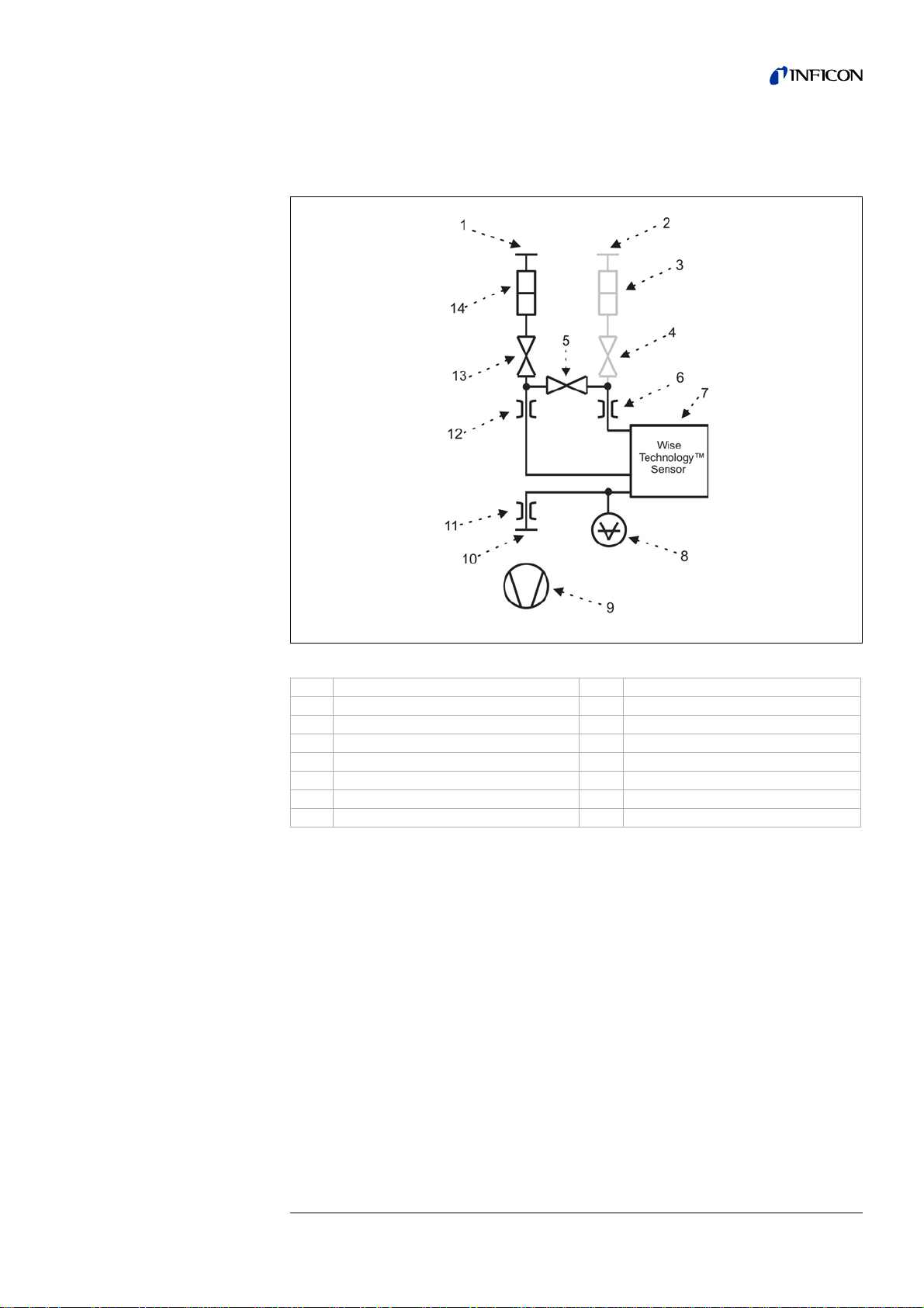
In the rare event that the sensor is contaminated with helium, only the valve V3 to the
reference inlet "Ref" is open, to purge the sensor. In this case, highly pure nitrogen
or external air has to be led to the reference inlet to decontaminate the sensor as fast
as possible.
Fig. 4-8 Valve configuration during decontamination
Item Description Item Description
1 Inlet “IN” 8 Pressure gauge p1
2 Reference “Ref” 9 Pump
3 Filter 2 10 Pump connector “OUT”
4 Valve V
5 Valve V
6 Throttle 2 13 Valve V
7 Wise Technology™ Sensor 14 Filter 1
3
2
11 Throttle 3
12 Throttle 1
1
jina85e 3.fm Technical Handbook(1112)
16 Description
Page 19
In FINE measurement mode, V1 and V2 are open, V3 is closed (see Fig. 4-9). The
sensor receives only gas from the measurement inlet and shows the highest sensitivity to helium from the measurement line.
Fig. 4-9 Valve configuration in FINE mode
Item Description Item Description
1 Inlet “IN” 8 Pressure gauge p1
2 Reference “Ref” 9 Pump
3 Filter 2 10 Pump connector “OUT”
4 Valve V
5 Valve V
3
2
6 Throttle 2 13 Valve V
7 Wise Technology™ Sensor 14 Filter 1
11 Throttle 3
12 Throttle 1
1
jina85e 3.fm Technical Handbook(1112)
Description 17
Page 20
In GROSS measurement mode, V1 and V3 are open, V2 is closed (see Fig. 4-10).
This way, the Wise Technology™ Sensor only receives little helium from the measurement line and normally even less helium from the reference line.
Fig. 4-10 Valve configuration in GROSS mode
Item Description Item Description
1 Inlet “IN” 8 Pressure gauge p1
2 Reference “Ref” 9 Pump
3 Filter 2 10 Pump connector “OUT”
4 Valve V
5 Valve V
6 Throttle 2 13 Valve V
7 Wise Technology™ Sensor 14 Filter 1
3
2
11 Throttle 3
12 Throttle 1
1
Other valve configurations than described above are not used by the software and
cannot be set by the user.
18 Description
jina85e 3.fm Technical Handbook(1112)
Page 21

3.4 Wise Technology™ Sensor
The helium detector (Wise Technology™ Sensor) consists of a closed glass
container with a measurement device for the precise determination of the pressure
inside the glass housing and a membrane chip with a large number of small quartz
windows.
The membrane is permeable only for helium; the membrane avoids all other co mponents of air from entering the glass housing.
The quartz membrane is heated so that the permeation for helium is sufficie ntly high
and fast.
Inside of the glass housing, the total pressure is measur ed precisely. As only helium
can enter the glass housing, the total pressu re is equa l to the pa rtial pressure of
helium.
The determined total pressure inside the housing is p roportional to the helium partial
pressure outside the sensor.
jina85e 3.fm Technical Handbook(1112)
Description 19
Page 22
3.5 Accessories
1
9
12
11
2
3
4
5
14
6
7
8
10
13
In addition to the main unit, two different types of the control panel and the corresponding connection cables are available.
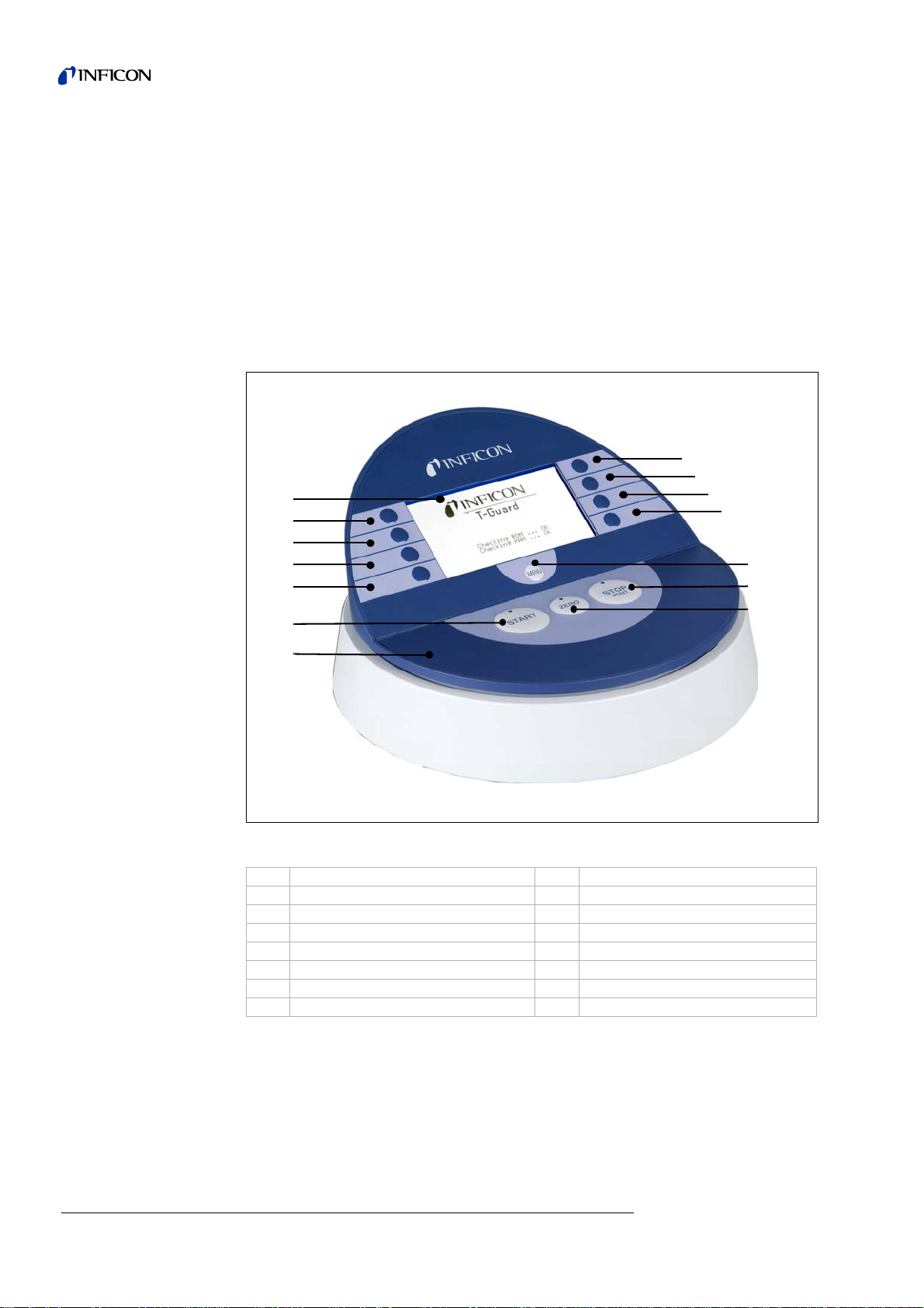
3.5.1 Control unit for desktop operation
Install the control panel on a flat workbench to avoid slipping. It is used to control all
functions and read all values of the T-Guard™ Leak Detection Sensor.
The control panel contains an LC Display, START, S
and also 8 soft keys to navigate in the menu on the display and to enter values.
TOP, ZERO and MENU buttons
Buttons
20 Description
Fig. 4-11 Soft keys of the control unit
Item Description Item Description
1 LC Display 8 Soft key No. 5
2 Soft key No. 1 9 Soft key No. 6
3 Soft key No. 2 10 Soft key No. 7
4 Soft key No. 3 11 Soft key No. 8
5 Soft key No. 4 12 MENU button
6 START button with LED 13 STOP / VENT button with LED
7 Control Unit 14 Z
START button
Notice All 3 LEDs in the buttons are inactive with T-Guard™ Leak Detec tio n
ERO button with LED
Sensor.
jina85e 3.fm Technical Handbook(1112)
Page 23
Press the START button to start a measurement using the selected method. The
measurement will then finish automatically.
STOP button
Press the STOP button to cancel the measurement immediately.
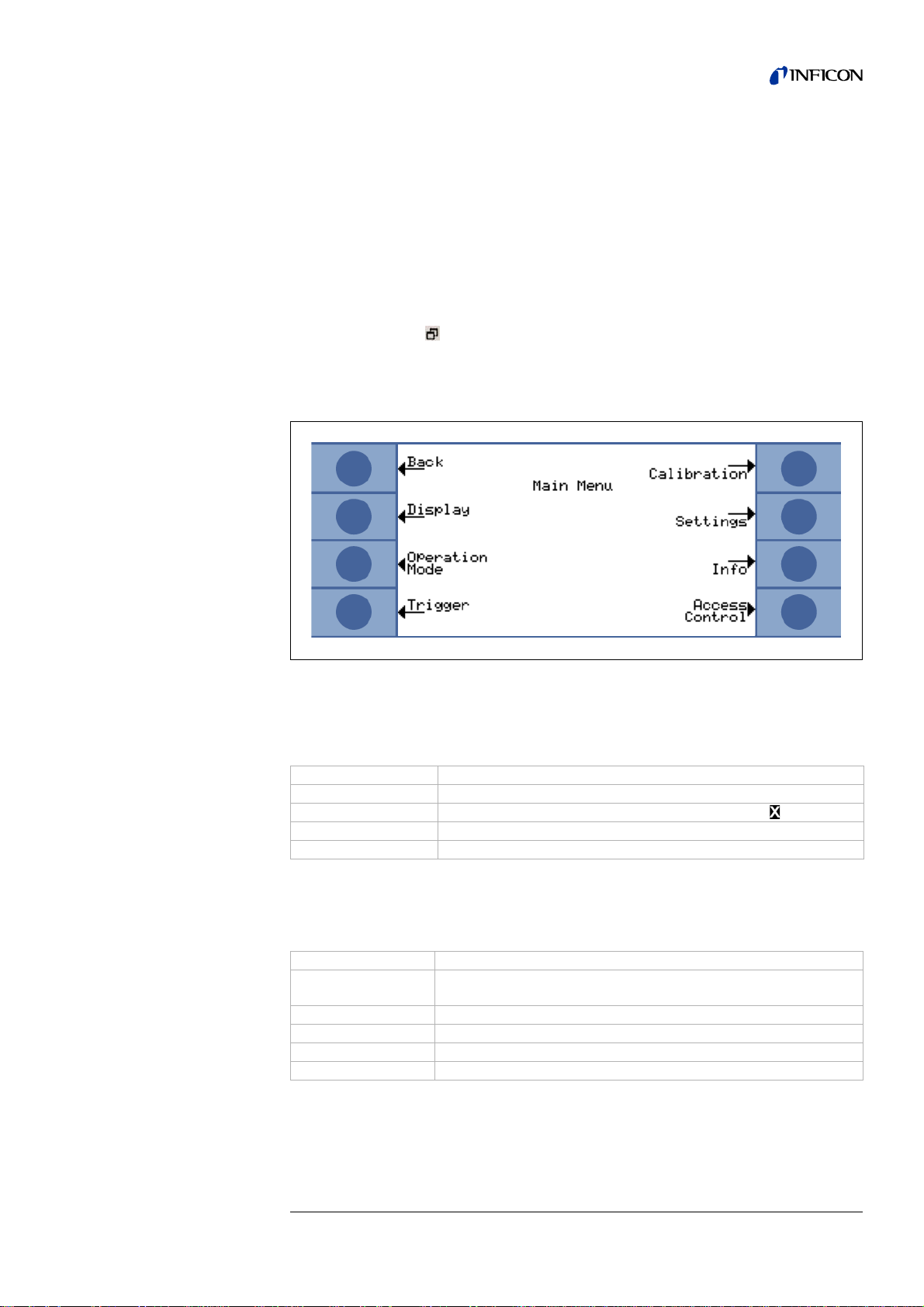
MENU button
In order to change the settings or to read information about T-Gua rd™ Leak Detection Sensor, open the menu by pressing the MENU button or the Soft Key (No.4) with
the MENU symbol ( ).
You will go back to the position in the menu you left before.
By pressing the M
ENU button again you will get back to the m easurement menu. By
pressing the MENU button for two seconds you will get into the main menu.
Fig. 4-12 Main Menu appearance
Soft Keys
The functions of the 8 soft keys depend on the currently opened menu.
Soft key No. 1 Description
1 and 8 very often have the functions B
4 often has the function to completely leave the menu ( )
ACK / ESC and OK, in this order,
MENU button Enter/Leave the menu
Entering values and units
The numerical values are entered in the the MENU page as follows:
Soft key No. 1 Description
SC-button)
1 (E
2( ↑ ) increments the numerical value.
3( ↓ ) decrements the numerical value.
6 and 7( ↑ and ↓ ) changes the unit
8 (OK) saves the entered value.
jina85e 3.fm Technical Handbook(1112)
leave this menu page and return to the previous menu page. The
value will not be changed.
Description 21
Page 24
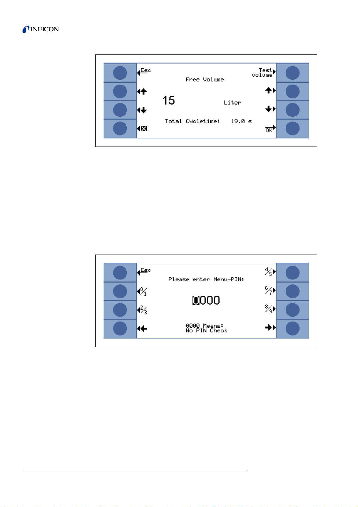
Fig. 4-13 You can change the value and the unit on this menu page
Entering the Menu-PIN
1 Press the ESC-button (soft key No.1) to leave this menu page and to return to the
previous menu page. The Menu-PIN will then neither be changed nor be entered.
2 Pressing a number button opens a submenu where you can select one of these two
numbers. After that, the cursor moves to the next digit to the right.
3 You can move the cursor to the left or to the right using the soft keys No. 4 and 8.
( ← and → ).
4 OK appears for soft key No. 8 when the last digit has been reached.
5 Pressing OK causes the PIN to be stored.
Status Line in the Display
22 Description
Fig. 4-14 Entering the Menu-PIN
The lowest line of the display is the status line. It shows general information, for
instance, the actual measurement mode.
jina85e 3.fm Technical Handbook(1112)
Page 25
3.5.2 19" control unit
You can insert this control unit in a 19’’ rack or in a panel cut-out as shown in Section
8.5.
This control panel is used in the same way as it is for the desktop control unit, only
the START, STOP and ZERO buttons are at other positions.
Fig. 4-15 Control unit for the installation in a 19"-rack
On its front side, the 19"-control unit refers to protection class IP40.
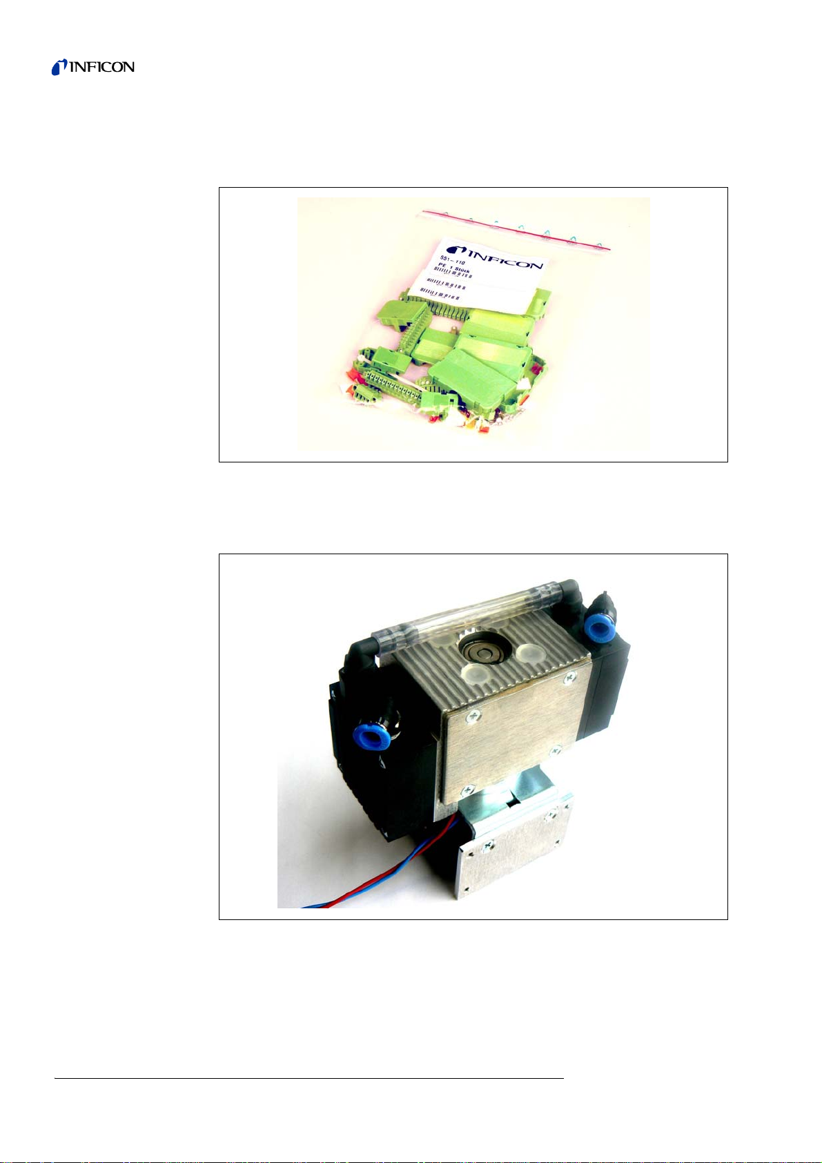
3.5.3 Connection Cable for Control Unit, 5 m
This cable connects the control unit and the T-Guard™ Leak Detection Sensor.
Fig. 4-16 Connection cable for control unit, cat. No. 551-102
jina85e 3.fm Technical Handbook(1112)
Description 23
Page 26
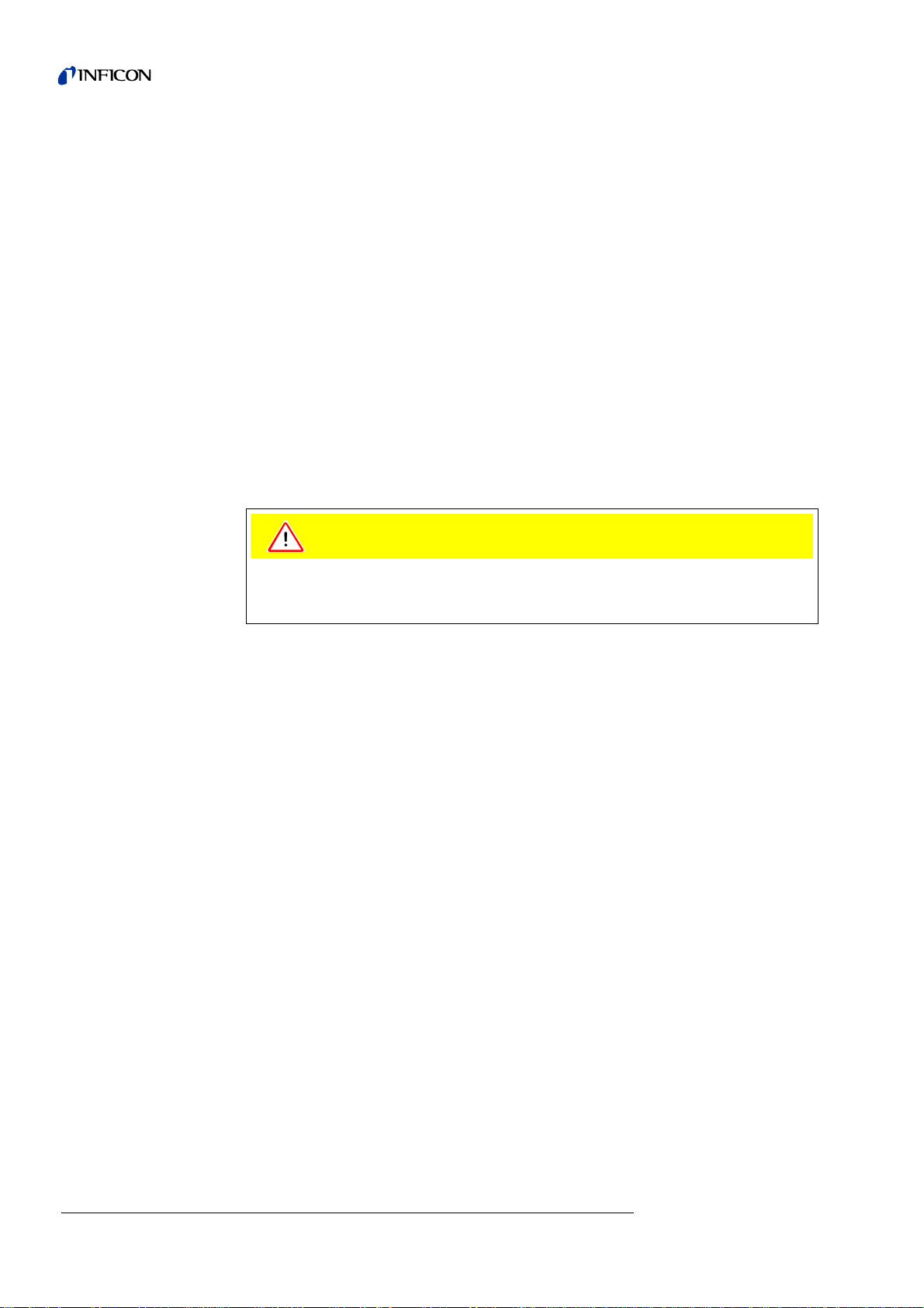
3.5.4 Connector set
The connector set includes all Phoenix connectors for connecting the electrica l interfaces.
Fig. 4-17 Connector set, cat. No. 551-110
3.5.5 Fore Pump
24 Description
Fig. 4-18 Fore pump, cat No. 200 002 929
This fore pump has two stages, is brushless and runs with a supply voltage of
24 V DC.
jina85e 3.fm Technical Handbook(1112)
Page 27

3.5.6 2m line
Fig. 4-19 2m line, cat. No. 200 002 793
In case your chamber is more than 50 cm away from the T-Guard, you must use
these 2m lines and shorten them if necessary. Both lines must have the same length.
Lines longer than 2m cause measurement errors.
3.5.7 I•Stick
Fig. 4-20 I Stick, cat. No. 200 001 997
Chapter 5.7 describes how to use the I Stick.
jina85e 3.fm Technical Handbook(1112)
Description 25
Page 28

3.5.8 Set of filters
Fig. 4-21 Filter set, cat. No. 200 001 680
Plugged filters cause pressure warnings. Check the filters every 6 months and
replace them no later than every 2 years.
3.6 Scope of delivery
• Main unit of the T-Guard™ Leak Detection Sensor
• Reference and measurement line with filters
26 Description
Fig. 4-22 Reference and measurement line with filters
jina85e 3.fm Technical Handbook(1112)
Page 29

3.7 Ordering Information
Description Cat. no.
T-Guard™ Leak Detection Sensor 540-001
T-Guard™ Leak Detection Sensor, version profibus 540-002
Control Unit for Desktop Operation 551-100
Control unit for the installation in a 19"-Rack 551-101
Connecting cable for the control unit, 5 m 551-102
Connecting cable for the control unit, 1 m 551-103
Set of connectors 551-110
I•Stick 200 001 997
Set of fuses 200 002 489
Set of filters 200 001 680
I/O test box 200 002 490
Power supply connection 200 002 496
Chamber connector 200 002 615
Measuring line 210 x 2 x 2 m 200 002 793
Fore pump, 24 V, two-step, brushless 200 002 929
jina85e 3.fm Technical Handbook(1112)
Description 27
Page 30

28 Description
jina85e 3.fm Technical Handbook(1112)
Page 31

4 Installation
Caution
Caution
Caution
4.1 Unpacking
Unpack the T-Guard™ Leak Detection Sensor immediately after receipt even if it is
to be put into operation at some later date.
Examine the shipping container for any external damage.
Completely remove all packaging materials.
Notice The three hose connectors are protected by plugs. Please only remove the
Notice Retain the shipping container and the packaging materials. Perhaps it will
Check if the T-Guard™ Leak Detection Sensor is complete (see Section 3.6) and
carefully subject it to a visual inspection. If any damage is discovered, please
immediately inform the forwarding agent and the insurers. If it is necessary to
exchange the damaged part, please contact our orders department.
After unpacking T-Guard™ Leak Detection Sensor, you have to care for a proper
installation:
plugs when you connect the hoses to the T-Guard™.
be required in the event of claims for compensation.
4.2 Installing Mechanically
Ensure sufficient ventilation.
In order to ensure adequate ventilation of the T-Gu ard™ Leak Detection Sensor, a
gap of at least 20 cm must be provided on top. Avoid heat sources being in the
vicinity of the T-Guard™ Leak Detection Sensor.
Do not block the ventilation inlets and outlets of the T-Guard™. Doing so could
damage the device.
Do not forget to attach the filters on the ends of the test an d re fe re nc e line s. T he y
protect the hoses from clogging and the sensor from dust contamination.
Notice T-Guard™ Leak Detection Sensor must be isolated from any vibration.
Vibration may lead to false measurement results!
jina85e 4.fm Technical Handbook(1112)
Installation 29
Page 32
The T-Guard™ Leak Detection Sensor can be used in each orientation. You can
Caution
unscrew the rubber feet and use these holes to fasten the main unit.
Please only remove the plugs when you connect the hoses to the T-Guard™. At the
time of delivery, the T-Guard is filled with helium-free nitrogen. This avoids helium to
penetrate into the sensor.
The T-Guard™ Leak Detection Sensor must be installed near the test chamber,
since the standard measuring line is only 50 cm long (measur ing line 2m leng th see
3.5.6).
Notice Changing the length or inner diameter of the test line affects the
measurement speed and results.
Notice Apply grease to the outside of the ends of the gr een measurement lines in
a thin film to be able to slide them into the connections until they snap in.
Otherwise it can happen that they are not deep enough in the connector
and measuring errors can appear.
4.3 Choosing a Fore Pump
The T-Guard™ Leak Detection Sensor stops working when oil penetrates into it
from one of the fore pumps.
Arrange the pumps with oil seal below the T-Guard™ Leak Detection Sensor.
You can use any vacuum pump with a gas flow of more than 200 sccm at a base
pressure of less than 50 mbar.
Connect the vacuum pump with a 6 mm tube to the tube connector labelled with
"
OUT" .
30 Installation
jina85e 4.fm Technical Handbook(1112)
Page 33

4.4 Installing Electrically
Caution
The T-Guard requires a 24 V DC power supply (tolerance ± 10 %).
A wrong polarity triggers the fuse.
The power supply should be able to supply a current of maximum 6 A. Typically, the
T-Guard needs 70W.
The following maximum cable lengths have to be met:
0.75 mm² 8.5 m
AWG 18 10 m
1mm² 10m
AWG 16 15 m
1.5 mm² 17.5 m
AWG 14 25 m
Notice Do not power up the power supply before having attached all other cables
you need!
Power Connector
Only two of the four pins are used for the power supply. The plus po le is marked with
„1+“, the minus pole is marked with „2-“.
4.5 Connecting the control unit
The CONTROL UNIT output of the T-Guard™ can be damaged when the cable is
disconnected or connected during operation.
Only plug or pull the cables when the T-Guard™ is switched off.
Attach one end of the control unit cable to the connector CONTROL UNIT of the TGuard™ Leak Detection Sensor and the other end to the control unit itself. Now TGuard™ Leak Detection Sensor can be operated via the control unit.
jina85e 4.fm Technical Handbook(1112)
Installation 31
Page 34

4.6 Connecting a PLC
4.6.1 Selection of functions assigned to the PLC inputs.
Select the PLC inputs as follows:
Main Menu
In the sub-menu S
of the I/O-connector (suitable for PLC-inputs) shall be assigned to which command.
Please find a complete list of the input commands and their meanings below:
Command Explanation
START Starts a measuring cycle.
STOP Stops a measurement cycle. You will not get a valid leak rate.
START/STOP Starts and stops a measurement cycle if switched to HIGH or
CAL Starts a calibration.
PROOF Starts checking the calibration with the proof leak rate.
CLEAR Clears errors and warnings. T-Guard™ Leak Detection
READY Wakes up the T-Gu ar d™ Lea k De te ctio n Sen so r from
STANDBY Puts the T-Guard™ Leak Detection Sensor on Standby
GROSS / FINE Switches between GROSS and FINE measurement.
PURGE Purges the measurement line as long as input is high. The
INV START electrically inverted START command
INV STOP electrically inverted STOP command
STOP/START Stops and starts a measurement cycle, if switched to HIGH
INV CAL electrically inverted CAL command
INV PROOF electrically inverted PROOF command
INV CLEAR electrically inverted CLEAR command
INV READY electrically inverted READY command
INV STANDBY electrically inverted STANDBY command
FINE / GROSS Switches between FINE and GROSS. Only available in Conti-
INV PURGE electrically inverted PURGE command
→
Settings → Interfaces → Select PLC Inputs.
ELECT PLC INPUTS, you can set which pin
If the T-Guard™ Leak Detection Sensor was in STANDBY the
start will be delayed by some seconds.
LOW , respectively.
A successful calibration changes the calibration factor.
Sensor restarts in case of an error.
Standby mode.
mode. This enlarges the sensor lifetime.
Only available in Continuous Mode.
helium sensor signal will be ignored.
Only available if auto-purge is off.
and LOW, respectively.
nuous Mode.
32 Installation
To change the commands assigned to the input- pins, select the appropriate pin using
the UP and DOWN arrows on the left side of the display.
Then select the desired command from the list of commands using the UP and
jina85e 4.fm Technical Handbook(1112)
Page 35

DOWN buttons on the right side of the display.
Press OK to save your settings. A screen with all selected settings will be displayed
for your reference.
Confirm with OK again.
Notice Most PLC functions are activated when the input signal rises. Having a
High-signal when starting the T-Guard™ Leak Detection Sensor is not
enough.
Fig. 5-1 Selecting the PLC Inputs
jina85e 4.fm Technical Handbook(1112)
Installation 33
Page 36

4.6.2 Electrical connection of the PLC inputs
Caution
1
2
3
4
5
6
7
PLC IN/OUT
24V
The default setting is as follows:
Pin Command Explanation
1Start
2Stop
3Cal
4Proof
5 Clear:
6 Standby
7 Common Common negative pole for all PLC inputs.
Connect to the negative pole of the power supply.
Max. permissible input voltage of the digital inputs: 28 V.
Signal level:
24 V (low-resistance) means High,
0 V (high-resistance) means Low,
Change from LOW to HIGH:
The programmed command for the input is enabled (edge controlled).
Fig. 5-2 Electrical connection of the PLC inputs
34 Installation
jina85e 4.fm Technical Handbook(1112)
Page 37

4.6.3 Selection of functions assigned to the PLC outputs.
Main menu→Settings→Interfaces→Define PLC outputs
In the sub-menu D
of the I/O connector (suitable for PLC outputs) shall be assig ned to which command.
Signal Explanation
OPEN low-resistance, for testing purposes
CLOSE: high-resistance, for testing purposes
TRIGGER 1 low-resistance means Trigger 1 was exceeded
TRIGGER 2 low-resistance means Trigger 2 was exceeded
READY low-resistance means the T-Guard™ is ready for the next
CYCLE ACTIVE low-resistance means the T-Guard™ Leak Detection Sensor is
STANDBY low-resistance means that the T-Guard™ Leak Detection
ERROR low-resistance means an error has occurred
WARNING low resistance means there is an outstanding warning
ERROR / WARN low-resistance means an error has occurred or there is an
CAL ACTIVE low-resistance means a calibration is running right now
REC. STROBE low-resistance means the recorder output is invalid for 300 ms
MEASURE low-resistance means that the T-Guard™ Leak Detection
GROSS / FINE low-resistance means that the T-Guard™ Leak Detection
GROSSLEAK low-resistance means the highest trigger value was exceeded
CONTAMINATED low-resistance means the sensor was contaminated with too
INV TRIGGER 1 high-resistance means Trigger1 was exceeded
INV TRIGGER 2 high resistance means Trigger2 was exceeded
INV READY high-resistance means the T-Guard™ is ready for the next
EFINE PLC OUTPUTS, you can set which pin
measurement. In Continuous Measurement mode, the TGuard measures the reference line.
just performing a measurement cycle This includes automatic
purging and reference measurement in Carrier Gas mode.
There is no measuring cycle in Continuous Measurement
mode. That is the reason why the output is always high-resistive.
Sensor is just in Standby mode
outstanding warning
because of changing the decade of LR Mantissa and LR
Exponent.
Sensor is just measuring. The leak rate of the last measurement is on when this output and also the REC STROBE output
are high-resistive.
Sensor is just in GROSS mode
by at least the factor 5.
much helium. In this case, immediately purge the reference
line with external air or nitrogen to decontaminate the sensor.
measurement. In Continuous Measurement mode, the TGuard measures the reference line.
jina85e 4.fm Technical Handbook(1112)
Installation 35
Page 38

Signal Explanation
INV CYCLE ACTIVE high-resistance means that the T-Guard™ Leak Detection
Sensor is performing a measurement cycle. This includes
automatic purging and reference measurement in Carrier Ga s
mode. There is no measuring cycle in Continuous Measurement mode. That is the reason why the output is always highresistive.
INV STANDBY high-resistance means that the T-Guard™ Leak Detection
Sensor is just in Standby mode
INV ERROR high-resistance means an error has occurred
INV WARNING high resistance means there is an outstanding warning
INV ERROR / WARN high-resistance means an error has occurred or there is an
outstanding warning
INV CAL ACTIVE high-resistance means a calibration is running right now
INV REC. STROBE high-resistance means the recorder output is invalid for 300 ms
because of changing the decade of LR Mantissa and LR
Exponent.
INV MEASURE high-resistance means that the T-Guard™ Leak Detection
Sensor is just measuring. The leak rate of the last measure-
ment is on when this output and also the REC STROBE output
are high-resistive.
FINE / GROSS high-resistance means that the T-Guard™ Leak Detection
Sensor is just in GROSS mode
INV GROSS LEAK high-resistance means the highest trigger value was exce eded
by at least the factor 5.
INV CONTAMI-
NATED
high-resistance means the sensor was contaminated with too
much helium. In this case, immediately purge the reference
line with external air or nitrogen to decontaminate the sensor.
To change these settings, select the appropriate pin with the UP and DOWN arrows
on the left side of the display.
Then select the desired setting from the list of settings with the UP and DOWN
buttons on the right side of the display. Press OK to save your settings.
A graphic with all selected settings will be displayed for your reference.
Confirm with OK again.
Fig. 5-3 Selecting the PLC Outputs
jina85e 4.fm Technical Handbook(1112)
36 Installation
Page 39

4.6.4 Electrical connection of the PLC outputs
Caution
16
8
9
10
11
12
13
24V
14
15
PLC IN/OUT
The default setting is as follows:
Pin Command Explanation
8 Trigger 1
9 Error/Warning
10 Ready
11 Measure
12 Standby
13 Rec. Strobe
14 Warning
15 Cal active
16 Common Common connection for all PLC outputs.
This contact can be used as the positive or the negative
pole.
The maximum permissible voltage for the output signals is 28 V.
The maximum total current for the output pins 8 - 11 is 0.75 A.
The maximum total current for the output pins 12 - 15 is also 0,75 A.
Permissible output current Max. 125 mA per output
Load resistance of outputs Min. 130 ohm per output
Supply voltage of
outputs
24 V DC
jina85e 4.fm Technical Handbook(1112)
Fig. 5-4 Electrical connection of the PLC outputs
Installation 37
Page 40
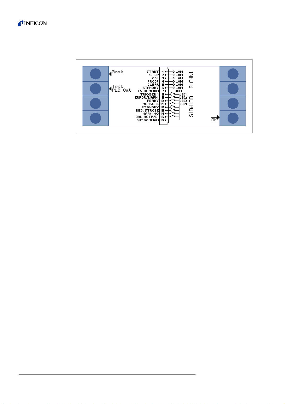
4.6.5 Overview of all settings
This screen shows the actual selected set-up of all input and output signals
Fig. 5-5 Overview of Inputs and Outputs
4.7 Connecting a PC
A computer can control the T-Guard™ Leak Detection Sensor via a standard RS232
cable (not a null modem cable) connected with the RS232 connector. The Inter face
Description document (iins85e1-a) explains how to do this in detail.
38 Installation
jina85e 4.fm Technical Handbook(1112)
Page 41

5 Operation
Caution
In order to work with the T-Guard™ Leak Detection Sensor, you need at least:
• Main unit with 3 hoses and two dust filters
• Fore pump
• Power supply unit 24 V / 6A
• Control unit with cabling (INFICON control unit, PC or PLC)
• Chamber
•Fan
• Test sample which has been filled with helium under pressure
To avoid early ageing of the sensor, prevent the re fere nce line from th e ingress of
helium!
If possible, lead external air to the reference line.
5.1 Running up
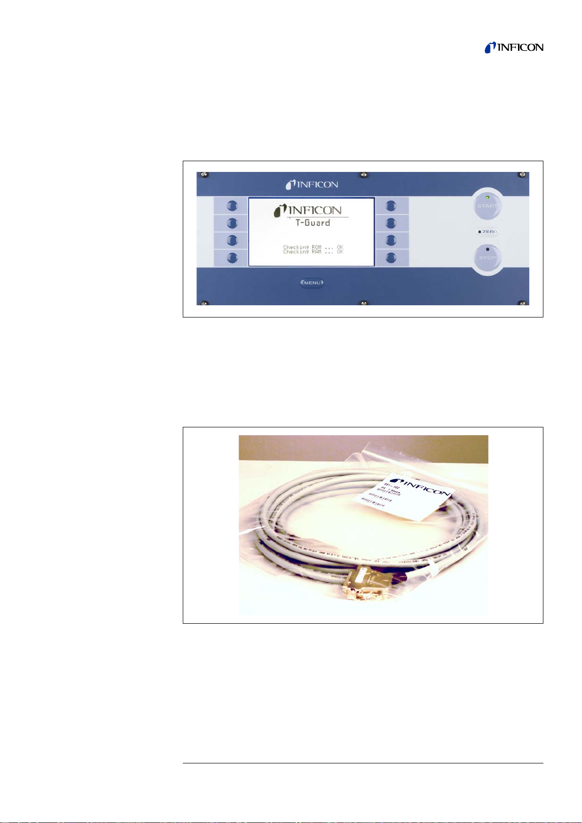
After switching on the T-Guard™ Leak Detection Sensor, the following display will
appear:
Fig. 6-1 Start screen
The T-Guard™ Leak Detection Sensor will start up when 24 V are applied to the
power supply connector.
jina85e 5.fm Technical Handbook(1112)
Operation 39
Page 42

Fig. 6-2 Estimated remaining time of the run-up period
The run-up process takes longer than 3 minutes if the device was turned off for a long
time. Once the T-Guard™ is ready for the measurement, the current measured value
of the leakage rate is displayed on the screen. Otherwise the device is activated with
a warning after 30 minutes at the latest.
The name of the current parameter set is displayed in the top line of the Leak Rate
screen. If the parameter set is changed later, there will be an asterisk befo re the
name of the parameter set.
Fig. 6-3 The T-Guard™ is now ready for measurement.
Changing Contrast
40 Operation
Notice If the T-Guard™ Leak Detection Sensor has been switched off for several
days, the initial sensor current may be too high to measure with the hig hest
sensitivity. In this case, apply external air to the reference inlet and wait for
two hours.
Then, the T-Guard™ Leak Detection Sensor will meet its specification.
Using external air, the unit will display "Background OK".
You can change the image contrast of the display during the run-up phase by
pressing Menu
→
Display→Contrast.
(The default value is 30)
jina85e 5.fm Technical Handbook(1112)
Page 43

5.2 Calibrating
3 x chamber volume (in ccm)
Carrier gas flow (in ccm per seconds)
-------------------------------------------------------------------------------------------------- -
Before you measure, you should set-up the unit according to your measuring
arrangement and calibrate it. This ensures that the unit will really be able to measure
what you want to.
5.2.1 Preparing Calibration
Before calibrating the T-Guard™, you should follow these steps in the described
order:
For the Carrier Gas mode:
1 Input the carrier gas flow (e.g from the mass flow controller, 30,000 sccm in
Settings
2 Change Trigger 1
3 Change the measuring time, when required (a shorter measuring time causes a
lower repeatability).
4 Enter the Calibration Leak Rate (must be higher than half of the trigger level)
5 Place the calibrated leak inside the chamber.
6 Close the chamber
7 Wait for a certain time which is calculated by:
→
Measurement Settings → Carrier Gas Flow)
8 Start the calibration (refer to Chapter 5.2.2)
For the Accumulation mode:
1 Enter the net volume (chamber volume minus sample volume)
2 Set Trigger 1
3 Change the measuring time, when required (a shorter measuring time causes a
lower repeatability).
4 Enter the Calibration Leak Rate (must be higher than half the trigger level)
5 Place the calibrated leak inside the chamber.
6 Close the chamber
7 Start the calibration (refer to Chapter 5.2.2)
Notice You can also view and edit all settings on one page in:
Main menu
Most important settings are on top, least important settings are on
the bottom of this table.
→
Info → View/Edit settings
jina85e 5.fm Technical Handbook(1112)
Operation 41
Page 44

5.2.2 Start Calibration
You can calibrate the T-Guard™ Leak Detection Sensor by selecting the following
submenu:
Main Menu
→
Calibration → Start Calibration.
Fig. 6-4 M
After the calibration routine, you can accept the new calibration factor by pressing
OK or cancel the calibration by pressing Esc. A calibration factor of less than 0.2 or
more than 5 will result in a warning instead of a successful calibration. Refer to
Chapter 9for possible causes of errors and warnings.
The ideal calibration factor you can get is 1. If the calibration factor is smaller than
0.5 or greater than 2, you can confirm but you will receive a warning as hint that you
can improve your measuring arrangement.
Notice You have to recalibrate for every change of free volume in accumulation
AIN MENU Calibration
mode and for every change of the carrier gas flow in Carrier Gas Mode.
This ensures a reliable measurement.
42 Operation
jina85e 5.fm Technical Handbook(1112)
Page 45

5.3 Measuring
Each measurement is started by the START button. A progress bar is displayed
during the measurement. When the measurement has finished, the display shows
the leak rate or an error message. The measurement can be cancelled at any time
by pressing STOP-button. The then displayed leak rate is a provisional value.
Fig. 6-5 Fine measurement, progress bar
5.3.1 Accumulation Mode
When you put a leak test sample filled with helium under pressure in an enclosed
chamber, the helium level in this chamber will rise over time. This is called "accumulation " (of helium). The difference of the helium levels at two different times reflects
the leak rate.
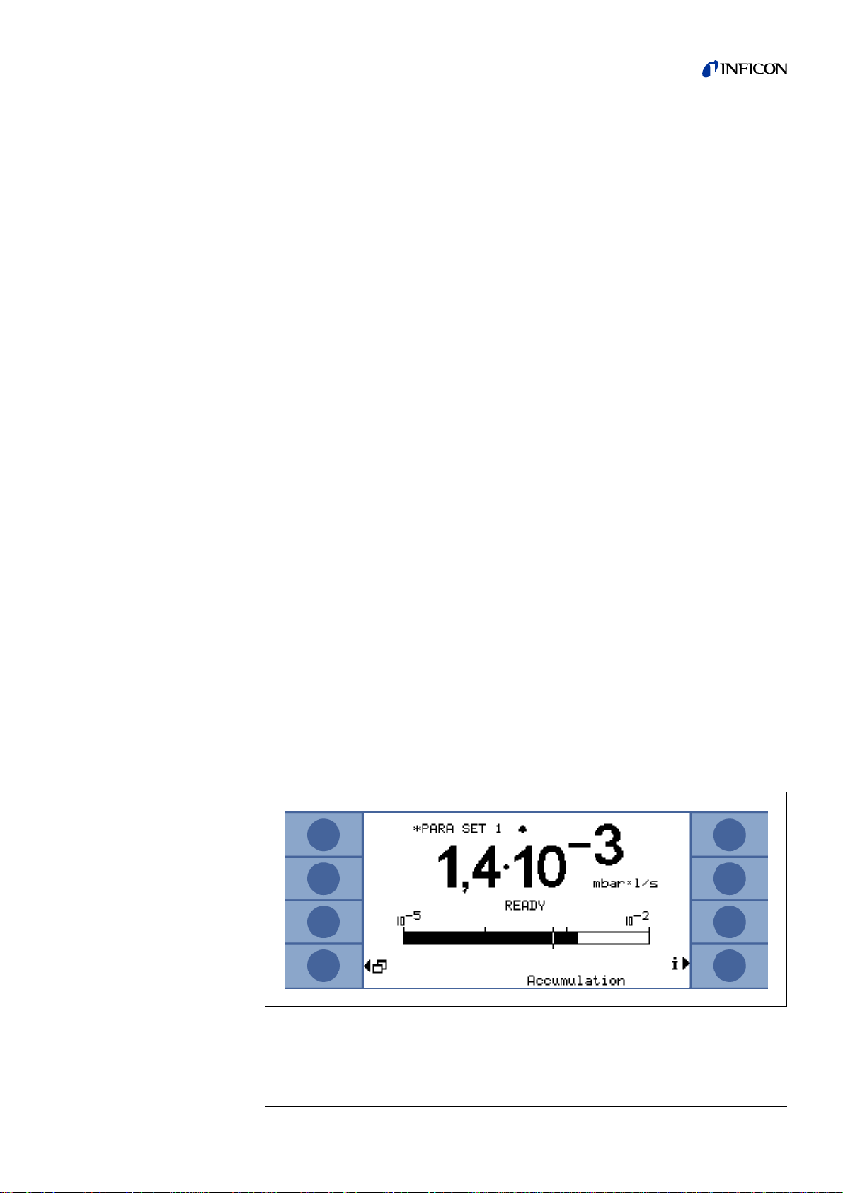
Fig. 6-6 Display of leak rate in Accumulation mode with information on the helium
background of the sensor and the environment.
jina85e 5.fm Technical Handbook(1112)
Operation 43
Page 46
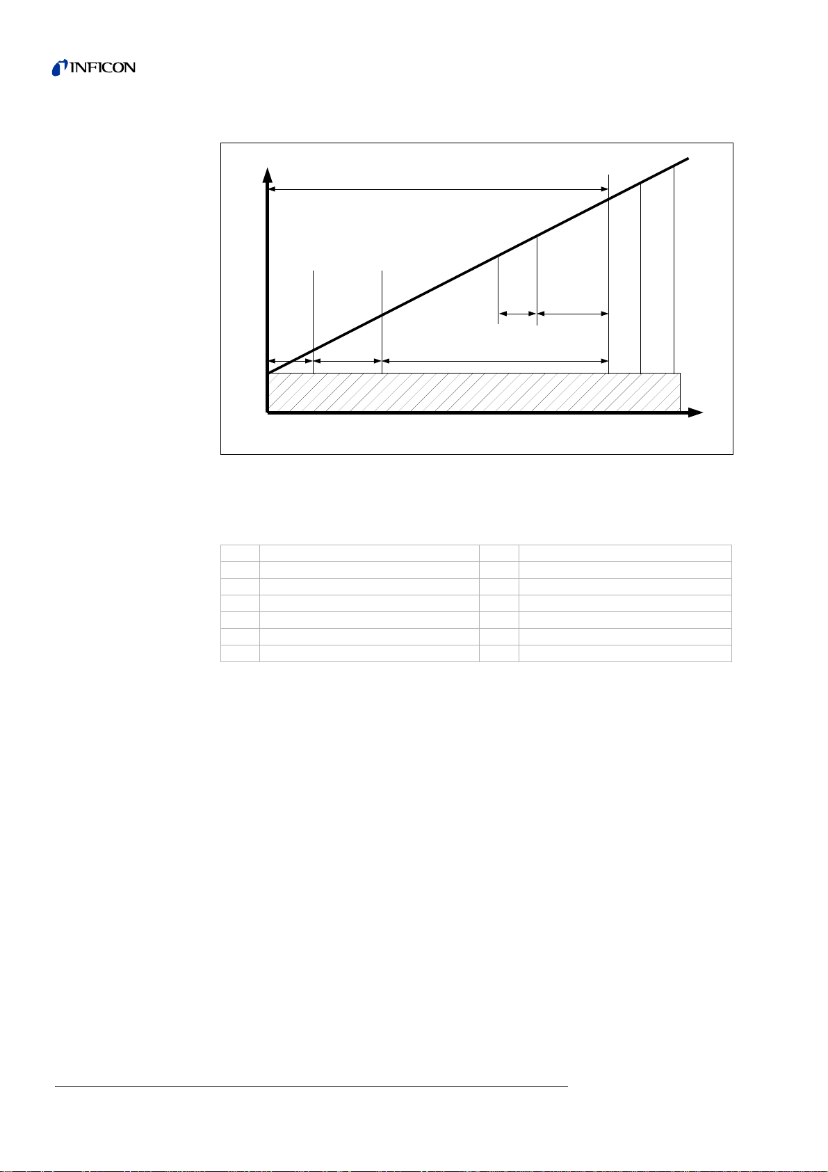
Accumulation Measurement
Fig. 6-7 Typical helium concentration in an enclosed chamber with a leaky test
sample over time. Due to ambient helium, the helium level is never zero.
The helium level rises linearly with time. The T-Guard™ Leak Detection
Sensor measures the helium concentration in the chamber four times.
Item Description Item Description
1 Helium concentration 7 Accumulation time
2 Start 8 Second gross measurement
3 Ambient helium 9 Second fine measurement
4 Time 10 Wait time purge
5 First gross measurement 11 Purge time
6 First fine measurement 12 Measuring time
In Accumulation mode, the T-Guard™ Leak Detection Sensor starts with the G
leak test. If, at the beginning of the test, the helium concentration in the chamber is
much higher (approx. 1000 ppm) than in the environment, the test sample has a
gross leak.
In this case, the T-Guard™ stops the measurement cycle and displays a leak rate o f
a hundred times the highest trigger value.
If the test sample passes the GROSS -leak test, the T-Guard™ Leak Detection
Sensor takes an air sample from the chamber and measures it in F
If, during this first
tration rises too fast, it will stop the measurement and report a leakage rate of five
times the highest trigger level.
After the first
GROSS measurement will be carried out to check if the test sample has exploded.
After that, it takes the next air sample in FINE-mode. From the difference of the two
F
INE-measurements, the T-Guard™ Leak Detection Sensor ca lculates the leak rate.
FINE measurement, the T-Guard™ detects that the helium concen-
FINE-measurement, it will wait for a certain time. Then, the second
INE-mode.
ROSS
jina85e 5.fm Technical Handbook(1112)
44 Operation
Page 47
Notice If the trigger value is higher than 1x10⁻³mbar l/s per litre of the net volume,
both test samples will be measured in GROSS-mode. Then you must use
outside air to purge the chamber. The h elium background on the reference
line must be really stable for GROSS-mode. If this is not possible, a bigger
chamber or diluted helium has to be used to measure in FINE-mode.
Notice If the T-Guard™stops the measurement due to a too high signal in G
mode, it reports a leakage rate of a hundred times the highest trigger level.
If it stops in F
trigger level.
In both cases, the PLC output "GROSSLEAK" is active.
After each accumulation measurement and waiting for a certain time, the chamber
will be purged. You can generally turn this automatic purge process off; it must then
be initiated with a control command every time.
5.3.1.1 Hints for a good measurement:
• Use fans inside the chamber to have a perfect mixture of helium and air
everywhere inside the chamber! The gas flow of the fans should be at least once
the chamber volume per second!
• Purge the test chamber before measurement!
An insufficient chamber purge is indicated with the warning W45.
• For best and repeatable results you must apply outside air to the reference inlet.
In order to have a more stable background on the reference inlet, put it loosely
into a tightly closed buffer volume. This buffer volume reduces the helium
background variations.
• Apply external air on the measurement line during the purge time in order to clean
it.
• You should purge the chamber after every measurement, then purge the
measurement line for at least 4 s, then wait for 2 s before performing the next
measurement. This removes the residual helium, which could affect the following
measurements, from the measurement system.
ROSS
INE mode for the same reason, it reports five times the highest
• The chamber must have neither slots nor holes. It must be sealed with rubber
gaskets. Only then are the measurements free from external influences.
Fig. 6-8 Display after finished measurement in Accumulation mode
jina85e 5.fm Technical Handbook(1112)
Operation 45
Page 48
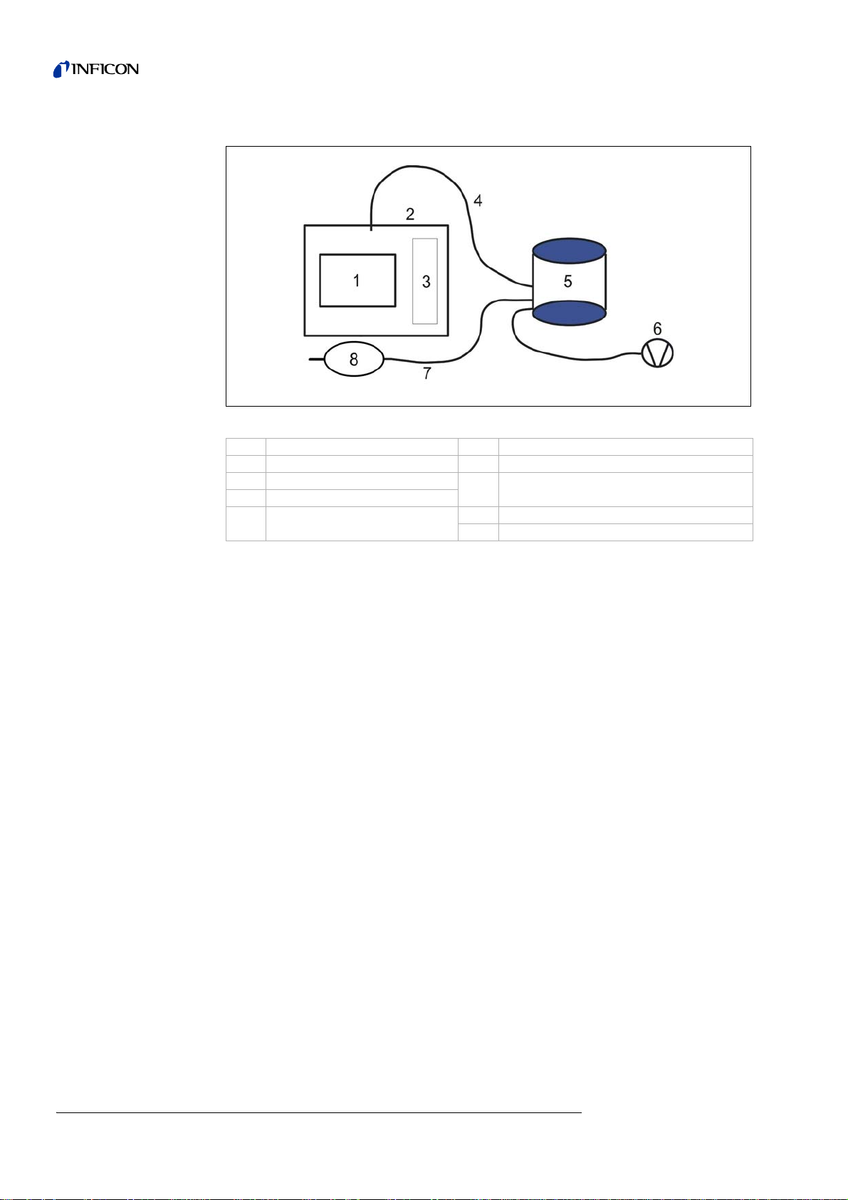
INFICON recommends this kind of set-up for Accumulation mode:
Fig. 6-9 Recommended settings for Accumulation mode
Item Description Item Description
1 Test sample 5 T-Guard™ Leak Detection Sensor
2 Testing chamber
3Fan
4 Measuring line connected
to the chamber
6 Fore pump exhaust air far apart from the
chamber
7 Reference line
8 Buffer volume > 4 litres
5.3.2 Carrier Gas Mode
In addition to the gas flow, which the T-Guard™ Leak Detection Sensor takes out of
a chamber, more air can be sucked through the chamber using a fa n or a pump.
This additional gas flow quickly carries the helium from the leak to T-Guard™ Leak
Detection Sensor. This way of leak detection is called Carrier Gas mode.
In Carrier Gas mode, the T-Guard™ Leak Detection Sensor measures the helium
content in the gas stream for a certain time. The helium signal from the end of the
measurement will be used in order to calculate the leak rate.
Carrier Gas mode can be used to detect bigger leaks faster than in Accumulation
mode.
The Carrier Gas mode is very sensitive to fluctuations of the helium background. An
elevated helium background is usually not stable.
46 Operation
jina85e 5.fm Technical Handbook(1112)
Page 49

Carrier Gas Measurement
Fig. 6-10 Typical helium concentration in an enclosed chamber with a leaky test
sample over time.
Item Description Item Description
1 Helium signal 4 Time
2 Start 5 Rising signal
3 Ambient helium 6 Stable signal, final value
Fig. 6-11 Display of leak rate in Carrier Gas mode with information on the helium
background of the sensor and the environment.
The bigger the chamber and the smaller the total gas flow through it, the longer it
takes for the signal to reach its final value.
The time you need to get a constant signal in Carrier Gas mode de pends on the total
gas flow and the volume of the chamber. The time it takes to see 63 % of the signal
is the volume of the chamber divided by the total gas flow.
For example: With a volume of 2 litres and a total gas flow of 20 l/s, you see 63 % of
the signal after 0.1 seconds. After waiting three times as long, you see 95 % of the
signal (0.3 s in this example). After five times as long, you will see 99 % of the signal
jina85e 5.fm Technical Handbook(1112)
Operation 47
Page 50

(0.5 seconds in this example). By increasing the total gas flow, the measurement will
3 x chamber volume (in ccm)
Carrier gas flow (in ccm per seconds)
-------------------------------------------------------------------------------------------------- -
be quicker but for the price of a lower sensitivity. The smallest displayable leakage
rate increases when the total gas flow is increased.
In order to save time, you can calibrate and measure with a shorter time than nee ded
for the final leak rate value. But then the completely identical timing for calibration
and each measurement is very important. This method is called Dynamic Measurement.
Like in the Accumulation mode, a GROSS measurement will be done before the
FINE measurement of the leak rate to avoid helium contamination of the Wise
Technology™ Sensor.
5.3.2.1 Hints for a good measurement:
• Minimize the chamber volume but do not let the test sample touch the walls.
• Place the inlet for external air in the chamber opposite the connection of TGuard™ Leak Detection Sensor.
• Use fans inside the chamber to have a good mixture of helium and air
everywhere.
• Do not make the outside air inlet too big. Helium must not leave the chamber
there.
• Lead the same ambient air into the chamber and the reference line.
• For a trigger leak rate of 1·10
sccm. For a trigger leak rate of 1·10
30,000 sccm. For a trigger leak rate of 1·10
higher than 300,000 sccm.
-5
mbar l/s, do not use a total flow higher than 3000
-4
mbar l/s, do not use a total flow higher than
-3
mbar l/s, do not use a total flow
• After closing the chamber and applying helium to the test object, wait for a cer tain
time, which amounts to:
INFICON strongly recommends this kind of set-up for Carrier Gas Measurement:
48 Operation
jina85e 5.fm Technical Handbook(1112)
Page 51

Fig. 6-12 Recommended set-up for Carrier Gas mode
Item Description Item Description
1 1,000 - 100,000 sccm 6 Air inlet, outside air
2 Dry pump or 7 Test sample
3 Pump exhaust far away from chamber 9 Testing chamber
4 Fore pump exhaust air far away from the
5 Reference line 11 T-Guard™
5.3.3 Continuous Mode
The Continuous mode is only developed for experts in the field of helium leak
detection.
Notice Use the STOP switch or even Standby mode when you do not need a
In Continuous mode, you are able to get a continuous signal from the Wise Technology™ Sensor after pressing START. Pressing STOP switches the valves in a way
that the reference line will be measured. G
selected by the user. The T-Guard™ Leak Detection Sensor will not deliver a leak
rate signal in this mode. Therefore, it will not be possible to set trigger values in Continuous mode.
It is in the duty of the user to interpret the cu rrent signal. The sensor current changes
by 1.5 x 10
Flow controlled fan 8 Fan
10 Measuring hose connected to
chamber
pump outlet
Leak Detection Sensor
measurement signal from T-Guard™ Leak Detection Sensor. Standby
mode will further clean up the Wise Technology™ Sensor and enlarge its
lifetime.
ROSS and FINE modes can and must be
-7
A per mbar of helium before the sensor.
jina85e 5.fm Technical Handbook(1112)
Operation 49
Page 52

Fig. 6-13 Display of the reference value in Continu o us mode.
Caution
5.3.4 Switching Off
You do not need to actively switch off the T-Guard™ Leak Detection Sensor. Just
switch off the power supply after usage.
5.3.5 Standby
The T-Guard™ Leak Detection Sensor will switch to standby mode automatically
after an adjustable time when it is not used. In addition to that, it is possible to switch
to standby mode manually via control unit, RS232 or digital input.
Do not switch off the power supply when the T-Guard™ Leak Detection Sensor is
contaminated with helium. This would reduce the sensor lifetime and increase the
time of the next run-up. Please wait until the T -Guar d is in Stan dby mod e or r eady
to measure (leak rate is displayed) before switching off the power supply.
5.3.6 Helium contamination
By default, the T-Guard™ Leak Detection Sensor uses its GROSS mode before each
measurement. Every time, when the T-Guard™recognises that the measured leak
rate exceeds five times the highest trigger value, it will stop the measurement cycle
instantly.
Due to these two facts, it is extremely unlikely that the sensor is contaminated with
helium.
If, nevertheless, the T-Guard™ should be contaminated, highly-pure nitrogen or
external air has to be pumped into the reference inlet to recover the sensor as fast
as possible.
The recovery time depends on the helium content of the air provided on the reference
inlet and the limit value of contamination. The lower the limit value of contamination
the faster the T.Guard will be ready for measurement again.
50 Operation
jina85e 5.fm Technical Handbook(1112)
Page 53

Notice When using the continuous measurement mode, a tr igg er le ve l canno t be
set. That is why you have to stop the measurement yourself as soon as you
see that the sensor current gets too high. In Continuous mode, the TGuard™ Leak Detection Sensor switches over to the reference line when
the sensor flow is greater than 1x10
5.4 Controlling via PLC
Basic functions and values of T-Guard™ Leak Detection Sensor can be controlled
and read by a PLC. Refer to chapter 4.6 for a detailed listing of all PLC commands
and signals.
Select PLC inputs in:
Main Menu
Select PLC outputs in:
→
-8
A.
Settings →Interfaces →Select PLC Inputs.
Main Menu
PLC outputs 1 - 4 are connected to the LEDs 1 - 4.
The measured leak rate is available at the
→
Settings→Interfaces→Define PLC-outputs
RECORDER output.
5.4.1 How to execute an accumulation measurement
You can start the measurement when READY is low-resistive.
During the measurement, the MEASURE output is low-resistive.
After the measurement, the MEASURE output is high-resistive. When the REC.
STROBE output will be high-resistive again, you can read the analog outputs. This
will happen after about 300 ms.
If the AUTOMATIC PURGING is enabled. READY will be low-resistive after purging.
Only then, the next measurements can be started.
5.4.2 How to execute a carrier gas measurement
You can start the measurement when READY is low-resistive.
During the measurement, the MEASURE output is low-resistive.
After the measurement, the MEASURE output is high-resistive. When the REC.
STROBE output will be high-resistive again, you can read the analog outputs. This
will happen after about 300 ms.
After the reference measurement, the READY output will be low-resistive again. This
takes as long as the FINE-measurement time. Only after the cycle has been finished,
the next measurement can be started.
5.5 Controlling via RS-232
Nearly everything that can be done with the control unit can also be done via the
jina85e 5.fm Technical Handbook(1112)
RS232 connection to a PC.
The Interface Description document explains how to do this (iins85e1-a).
Operation 51
Page 54

5.6 Configuring analog output
You can configure the analog output in the menu screen
Main Menu
in Analog Output and Analog Scale
Fig. 6-14 Configuration of analog outputs.
→
Settings→Interfaces
52 Operation
Fig. 6-15 Configuration of the scale of the analog outputs.
• In the setting "LR Exponent", the exponent results from the voltage as follows:
Exponent = (voltage x 2) -14
For example: A voltage of 4.5 V results in an exponent of (4.5 x 2) - 14 = -5.
• In the setting "LR Log.", the leak rate is calculated as follows:
Leak rate = final value x (10^((U - 10)/(volts/decade)) )
For example: With a final value of 10-1 mbar l/s and 2 V per decade, a voltage of 3.7
V results in a leak rate of 10
-1
10
mbar l/s x 7,08x10-4 = 7,08x10⁻⁵ mbar l/s.
For "Current Log.", it is similar for current instead of leak rate.
-1
mbar l/s x 10^((3.7-10)/2) = 10-1 mbar l/s x 10
-3,15
=
jina85e 5.fm Technical Handbook(1112)
Page 55

• In the setting "LR Linear", the leak rate is calculated as follows:
Leak rate = final value/10x voltage
For example: 10 V refer to the final value, e.g. 10-3 mbar l/s, then, 3.7 V refer to, e.g.
-4
3.7x10
For "Current Lin.", it is similar for current instead of leak rate.
The final value and the increase (volts/decade) have to be set separately in the
mbar l/s.
Main Menu
for the outputs 1..2 and 3..4.
The increase volts/ decade does not apply for linear values.
→
Settings→ Interfaces→Analog Scale
5.7 Using the I-Stick and the parameter sets
The I•Stick (Cat-No. 200001997) can be used to save up to 25 parameter sets and
to be able to copy them easily from one device to the other.
A parameter set comprises all settings except the language and the RS232 protocol.
Copying takes place as follows:
Fig. 6-16 Menu screen "Copy Parameters"
1 Go to Main Menu
→
Settings→Copy Parameters
2 On the left side, select your required parameter set . You can select between the
options Default Parameter Set, Current Parameter Set, three internal parameter sets
and up to 25 parameter sets on the I•Stick. If no I•Stick is connected, Copy does not
work. If the memory on the I•Stick is empty, the default parameter set will be copied.
3 On the right side, select the destination which the parameter set is to be copied to .
4 Now use "Copy" for copying the parameter set or "Edit name" to copy the parameter
set with a new name to the right side.
5 Before copying, the differences of the parameter sets are displayed from the right
and the left side for confirmation.
6 If copying was successful, you will return to the "Settings" menu, if not, you will
receive an error message and the "Copy Parameter" menu will be displayed again.
jina85e 5.fm Technical Handbook(1112)
Operation 53
Page 56

7 The name of the current parameter set is displayed in the top line of the leak rate
screen. If the parameter set is being changed later, a star will be written before the
name of the parameter set.
Notice Only insert or disconnect the I•Stick when the device is switched off. If the
I•Stick is connected or disconnected during operation, the device s canno t
recognize it.
Notice With the first use, the I•Stick is initialized. Switch the T-Guard off and on
again to be able to use the I•Stick
5.8 Settings
All Settings referring the configuration of the T-Guard™ Leak Detection Sensor are
provided in the menu structure.
5.8.1 Menu Structure Diagram
Starting in the Main Menu, all menu screens are arranged like a tree structure.
54 Operation
Fig. 6-1 Main Menu
Please find the menu structure of the T-Guard™ Leak Detection Sensor on the
following page.
In this diagram, all operations are listed.
Please find the descriptions of the individual menu items on the following pages.
jina85e 5.fm Technical Handbook(1112)
Page 57

Menu Structure T-Guard™
Back
Display
Operating Mode
Trigger
Calibration
Settings
Main menu T-Guard™ Leak Detection Sensor
Info
Access control
Contrast Invert display
Displayed limit
Accumulation
Carrier gas
Continuous Mode
Standby
Trigger level 1
Trigger level 2 Enabled
Leak rate ext. Proof leak
Start Proof Function
Proof Leak Rate
Start Calibration
Miscellaneous
Interfaces
Measurement Settings
Copy Parameters
Monitoring
View / Change Settings
Internal Data
Vacuum diagram
Interfaces
History & Maintenance
Cal Factor Set to 1
Service
Access to CAL Function
Change Menu PIN
Language
Time & date
Control location
RS232 Protocol
Select PLC Inputs
Define PLC Outputs
Analog Output
Analog Scale
He concentration
Standby time
Flow of Carrier Gas Test Flow
Line length
Set Times
Accumulation Volume Test Volume
Pressure Unit
Change name
Copy
Contamination Limit
Pressure Limits
Measurement list
Display error list
Maintenance History
Calibration History
On
Off
PLC
RS232
All
Local and PLC
Local and RS232
Local
ASCII
Binary
Print automatically
Baud rate
Analogue Output 1 .. 2
Analogue Output 3 .. 4
Set Times Automatic
Measuring time
Wait Time Purge
Purge time (+ on/off)
High
Normal
Low
jina85e 5.fm Technical Handbook(1112)
Operation 55
Page 58

5.8.2 Explanation of Menu Items
The menu items the explanation refers to are written in bold letters.
Main Menu →
Back
Returns to the previous page, does not alter any setting.
Main menu → Display →
Contrast
Here, you can change the image contrast of the display.
Possible values: 0 to 99.
Default setting: 25.
Contrast → Invert display
Inverts dark characters and light background to light characters and dark
background.
Lower Limit
Raises the lowest leak rate displayed.
Increase by factor 1 to 100 possible. Default setting: 2
Main menu → Operating mode →
Accumulation
Chooses Accumulation as operation mode after confirming it with OK.
Carrier gas
Chooses Carrier Gas mode for operation after confirming it with OK.
Continuous Mode
Chooses Continuous mode for operation after confirming it with OK.
Standby
Elongates sensor life time. Press START to restart.
Main menu → Trigger →
Trigger level 1
Enter the reject leak rate here.
This setting determines the measuring time and decides between gross and fine
measurement.
Possible values: 5E-6 mbar l/s to 9.9E-2 mbar l/s.
Default setting: 2E-5 mbar l/s.
Trigger level 2
jina85e 5.fm Technical Handbook(1112)
56 Operation
Page 59

Enter an additional trigger leak rate.
This setting strongly influences the measurement, if enabled. For instance, you can
extend the displayed range upwards by setting the trigger limit 2 to the five-fold value
of the trigger limit 1.
Possible values: 5E-6 mbar l/s to 9.9E-2 mbar l/s.
Default setting: 2E-5 mbar l/s.
Trigger level 2→ Enabled
Enables the use of the additional reject leak rate.
Default setting: Disabled.
Main menu → Calibration →
Leak rate ext. Proof leak
Enter the leak rate for verifying the calibration.
Possible values: 5E-6 mbar l/s to 9.9E-2 mbar l/s.
Default setting: 2E-5 mbar l/s.
Start Test Function
Connect a leak with the proof leak rate to check the calibration. In this procedure, the
calibration factor is only checked but not written newly. The proof leak rate may
deviate from the test leak rate and therefore, it has to be input separately.
Test Leak Rate
Enter the leak rate for checking the calibration.
Possible values: 5E-6 mbar l/s to 9.9E-2 mbar l/s.
Default setting: 2E-5 mbar l/s.
Start
Calibration
Use a leak with a calibration leak rate and start the calib ration. For a successful calibration, the determined calibration factor must be between 0 .2 and 5. If the calibration
factor is between 0.2 and 0.5, or 2 and 5, a warning will be output, however, also after
the confirmed calibration.
Main menu → Settings →
Measurement settings → He concentration
Here, you can set the helium concentration in the test sample which is applied for
filling. T-Guard™ changes the automatic measuring time accordingly and displays
the real leak rate of the leakage.
Possible values: 10% to 100%.
Default setting: 100%.
Measurement settings → Standby time
If the T-Guard™ Leak Detection Sensor is not in use within this time frame, it will
switch to Standby mode automatically.
jina85e 5.fm Technical Handbook(1112)
Operation 57
Page 60

Possible values: 10 s, 30 s, 1 min, 2 min, 5 min, 10 min, 30 min, 60 min, disabled.
Default setting: 10 min .
Measurement Settings → Carrier gas flow
This item is only available in Carrier Gas mode.
Enter the total gas flow in Carrier Gas mode here. T-Guard™ Leak Detection Sensor
itself uses a probe gas flow of 180 sccm in Fine mode and 90 sccm in Gross mode.
Possible values: 60 sccm to 1000000 sccm.
Default setting: 1000 sccm
Measurement settings → Carrier gas flow →
This item is only available in Carrier Gas mode.
The T-Guard™ Leak Detection Sensor can measure the total flow in Carrier Gas
mode if the proof leak rate is applied during setting.
Measurement settings
Here, you can set the length of the measuring line between 50 and 250.
For lengths longer than 50 cm, a set-up time of up to one second is set before the
real measurement starts.
This ensures that, for the gross test, the measuring signal is already on the sensor.
The the default value is 50 cm.
Measurement Settings
Here, you can enter several time values for the measurement.
Measurement Settings
Depending on the smallest trigger value and the total gas flo w/accumulation volume,
the T-Guard™ Leak Detection Sensor selects reasonable times for measurement.
→
Line length
→
Set Times
→
Set Times→Set Times Automatic
Flow test
58 Operation
Measurement times →
Enter the total measuring time here. The cycle time of the T-Guard™ Leak detection
Sensor is longer than the total measurement time.
Possible values: 9 s to 300 s (accumulation), 3 s to 66.7 s (carrier gas). Default
setting: automatic measuring time.
Measurement settings → Set times → Waiting time Purge
This item is only available in Accumulation mode.
After every accumulation measurement, the chamber will be purged after a certain
time after the measurement. Enter this waiting time here.
Possible values: 0.1 s to 300 s.
Default setting: 4 s.
Σετ Τιμεσ
→ Measuring time
jina85e 5.fm Technical Handbook(1112)
Page 61

Measurement settings → Set time → Purge time
This item is only available in Accumulation mode.
Enter here, how long the purge will take after the accumulation measurement The
automatic purging can be switched automatically in this screen. Only then, it is
possible to start purging by a command.
Possible values: 1 s to 50 s.
Default setting: 4 s.
Measurement settings → Accumulation vol. → Test Volume
This item is only available in Accumulation mode.
T-Guard™ Leak Detection Sensor can measure the accumulation volume in
Accumulation mode when the test leak rate is applied during setting up.
Measurement Settings → Accumulation Volume → Volume
This item is only available in Accumulation mode.
Enter the net chamber volume (chamber volume minus test sample volume) here.
Possible values: 0.01 l to 10000 l.
Default setting: 1 l.
Measurement settings → Pressure unit
Choose your favourite pressure unit.
Possible values: atm, Torr, PSI, Pa, mbar.
Default setting: mbar.
Main menu → Settings →
Interfaces → Control location
Select how the T-Guard™ Leak Detection Sensor shall be controlle d.
Possible values: PLC, RS232, all, local and PLC, local and RS232, local.
Default setting: All.
"Local" (control unit) means that neither the PLC nor the RS232 may start or stop a
device.
"RS232" means that neither the control unit nor th e PLC may start or stop a device.
"PLC" means that neither the control unit nor the RS232 may start or stop a device.
The operating unit is always allowed to be configured.
Use the Menu PIN to avoid it.
(Access control → Edit Menu PIN)
RS232 is always allowed to read values.
The PLC outputs are always active.
Interfaces → RS232 Protocol → ASCII
The ASCII protocol can be used to communicate with the T-Guard™ Leak Detection
Sensor by typing commands in a terminal program like Microsoft Hyperterm and
getting a human readable answer.
jina85e 5.fm Technical Handbook(1112)
This record is pre-set as standard.
Operation 59
Page 62

Interfaces → RS232 Protocol → Binary
The binary protocol can be used to communicate with T-Guard™ Leak Detection
Sensor by software, written by a programmer. This method of communication is very
fast. It is, for example, the fastest way to read a leak rate from the T-Guard™ Leak
Detection Sensor.
Interfaces → RS232 Protocol → Printer Auto
After each measurement, the T-Guard™ Leak Detection Sensor sends data via
RS232.
Date, Time, Parameter set name, Measurement mode, Leak rate, Trigger 1, [Trigger
2].
Interfaces → Select PLC inputs
In this screen, you can select which functions can be called from the 6 inputs.
For default settings refer to section 4.6.2.
Interfaces → Select PLC-outputs
In this screen you can choose which information will be present on the 8 outputs.
For default settings refer to section 4.6.4.
Interfaces → Scaling Analog Output → Analog Output 1 .. 2
In this screen, you can set the upper limit and the volts/decade for th e output on Pin
1 and 2.
Interfaces → Scaling Analog Output → Analog Output 3 .. 4
In this screen, you can set the upper limit and the volts/decade for th e output on Pin
3 and 4.
Interfaces→ Analog Output
In this screen you can choose which information will be present on the two analog
outputs.
Possible values: Off, Pressure, LR Mant, LR Exp, LR Lin, LR Log., Current Lin,
Current Log.
Default setting: 1..2: LR Exp, 3..4: LR Log.
Interfaces → Scaling Analog Output
In this screen, you can select how the voltage signal of the analog output has to be
interpreted, when "LR Log." or "Current Log." have been selected.
60 Operation
jina85e 5.fm Technical Handbook(1112)
Page 63
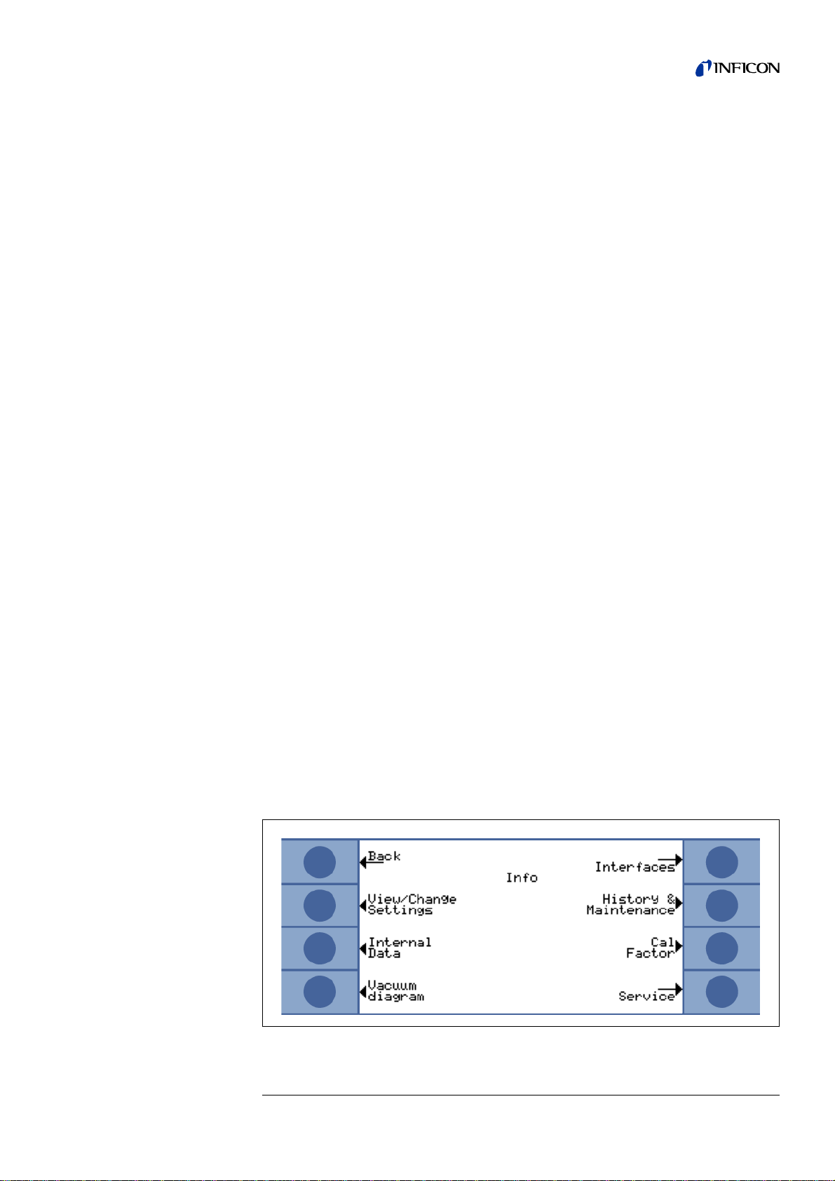
Main menu → Settings →
Miscellaneous → Language
Choose your favourite language.
Possible languages: English, German, French, Italian, Portuguese, Spanish,
Japanese (Katakana).
Default setting: English
Miscellaneous→ Time&Date
Set time and date, if necessary.
Main menu → Settings →
Copy Parameters
In this screen, you can copy parameter sets from the left side to the right side and
rename, if necessary.
Main menu → Settings →
Monitoring → Contamination limit
Set the contamination limit to "High" in order to be able to measure a high helium
content in the test gas. Set it to "Low" in order to protect the sensor from receiving
too much helium, which reduces the lifetime of the sensor. The default setting is
"Normal".
"Low" stops the measurement after 30 s at 40 ppm, "Normal" after 30 s at 75 ppm,
"High" after 30 s at 200 ppm, or in case of higher concentration after the relevant
shorter time (e.g. double concentration after the half time).
Monitoring → Pressure limits
Enter a permitted pressure range for the Wise Technology™ sensor here. Exceeding
the pressure limits will give a warning. Use this setting to be warned in case of
clogged filters or wrong test settings.
Possible values: Low limit: 10 mbar to 350 mbar, High limit: 250 mbar to 800 mbar.
Default settings: 180 mbar and 350 mbar. The high limit must be 100 mbar higher
than the low limit.
Main menu → Info →
jina85e 5.fm Technical Handbook(1112)
Fig. 6-1 Info menu
Operation 61
Page 64

View / Change Settings
In this screen, you can see the most important measurement settings and you can
also edit them, when allowed.
Fig. 6-1 View/Change settings menu
Internal Data
This menu item spans across several pages to show all kinds of internal data.
Vacuum diagram
This screen shows the vacuum diagram of the T-Gu a rd™ Le a k Dete ct ion Sens or
with its valve configuration.
Also sensor pressure, sensor current and an estimated helium concentration in ppm
are displayed.
Interfaces
This screen gives information about the settings of the interfaces.
History & Maintenance → Measurement list
In this screen, you can see the last 12 measured values.
History & Maintenance → Display Error list
In this screen, you can examine the last 12 errors and warnings.
History & Maintenance → Display Service list
In this screen, you can see the last 12 maintenance events.
History & Maintenance → Calibration list
In this screen, you can examine the last 12 calibrations.
jina85e 5.fm Technical Handbook(1112)
62 Operation
Page 65

Main menu → Info →
Cal Factor
This screen shows the actual calibration factor and its global limits. The calibration
factor should be near 1 for a good setting of the auto m at ic time s.
Possible values: 0.2 to 5.
Default setting: 1.
Service
This menu item is for authorized INFICON service personnel only.
Main menu → Access control →
Access to CAL function
Here, you can lock and unlock the access to the calibration function.
Change Menu PIN
Here, you can set or change a 4 digit PIN to prevent access to the menu via the
control unit. A Menu PIN of "0000" means, that no Menu PIN is assigned.
5.9 F.A.Q. - Frequently asked questions
Q: Why can the measurements not be reproduced?
A1: It is less possible to reproduce measurements when the T-Guard indicates
"moderate background" or "bad background".
Remedial measures: Decrease the background by checking the helium supply
for leaks. If possible, place the helium supply far away from the T-Guard.
Evacuate the test sample after the measurement in order to dispose of the
helium.
Purge the measurement chamber with ambient air. Carrier gas mode only works
if you have a constant pressure of 5 ppm of helium in the air.
A2: Measurements are less reproducible if the chamber has little slots or holes. A
calibration factor of 1.3 or more indicates that he chamber volume was entered
correctly.
A3: Measurements are less reproducible if the trigger level is a lot higher than the
measured leakage rate. The trigger level should be equal to the leakage rate to
be measured.
A4: Measurements are less reproducible if the measurement time was reduced too
much. This has the same effect as a trigger level that is too high.
A5: Measurements are less reproducible if the chamber fan is too weak. The fan
should circulate the chamber volume twice per second.
A6: Measurements are less reproducible if they are carried out in Only GROSS
mode. If this is the case, the T-Guard displays "Only GROSS" when changing the
trigger level.
Remedial measures: Avoid an Only GROSS measurement by using diluted
helium (and setting this) or by using a larger chamber.
jina85e 5.fm Technical Handbook(1112)
Operation 63
Page 66

A7: Measurements are less reproducible if you do not use the green measuring
hoses from INFICON. Hoses with an inside diameter of mor e than 1 mm canno t
be used.
A8: Measurements are less reproducible if the green hoses have not been inserted
completely into the couplings.
Apply a very thin grease film to the ends of the hoses in order to be able to insert
them completely. You notice this by the hose sliding into the coupling a second
time.
Q: Why does the measured leak rate get smaller and smaller when I do not
purge the chamber in between measurements?
A: Check the chamber for thin slots and small holes. Helium may escape there. This
leads to smaller leakage rates over time.
Remedial measures: Seal your chamber. Use the rubber gaskets for the
chamber lid.
Q: Why does the calibration not work?
A1: Enter the correct chamber volume and adjust the trigger level and the test
leakage rate to the used leakage rate.
If you use diluted helium, you must enter this in the device.
A2: Check all answers to the first question: "Why can the measurements not be
reproduced?"
Q: Why do I receive a warning after confirming the new calibration factor?
A: Your measurement set-up can and should be improved.
Remedial measures: Check the chamber volume, the chamber for slots and
holes, as well as the test leakage rate, the trigger level, the measuring time and
the fan.
Q: Why does the measured leakage rate increase over time?
A1: If the T-Guard has not been used for a long time, the sensor drifts a little
downwards. This drift becomes increasingly smaller, so that the measured
leakage rate may rise a little. The measurement should be stable after two hours.
A2: The test leak could take some time to stabilise.
Remedial measures: Use leaks from INFICON.
A3: The helium and air mixture takes a long time in your test sample.
Remedial measures: Evacuate the test sample as far as possible before filling it
with helium.
64 Operation
jina85e 5.fm Technical Handbook(1112)
Page 67

Q: Why does the follow-up measurement after a gross leakage return a leakage
rate that is too small?
A: Especially after measuring a gross leak, you should purge the measurement line
for at least 4 s with low-helium air, then wait for 1 s before performing th e ne xt
measurement.
This removes the residual helium, which could otherwise affect the following
measurements, from the measurement system.
jina85e 5.fm Technical Handbook(1112)
Operation 65
Page 68

6 Maintenance
Warning
Caution
For maintenance work, disconnect the T-Guard™ Le ak Detection Sensor from the
power supply.
6.1 Replacing the Inlet Filters
The T-Guard™ Leak Detection Sensor has two inlet filters.
The inlet filters should be checked for contamination at least every 6 months and
should be replaced no later than every 2 years.
Notice Always change both filters even if only one is clogged.
Fig. 7-1 Inlet filter attached
Item Description
1 Inlet Filter
Fig. 7-2 Inlet filter removed
Item Description
1 Inlet Filter
jina85e 6.fm Technical Handbook(1112)
66 Maintenance
Page 69

6.2 Replacing Hoses
Notice Measurement hose and reference hose must have the same length.
Notice Apply grease to the outside of the ends of the green measurement lines in
1 Push on the ring of the connection and pull the hose out.
a thin film to be able to slide them into the connections until they snap in.
Otherwise it can happen that they are not deep enough in the connector
and measuring errors can appear.
Fig. 7-3 Hose connections of the T-Guard™ Leak Detection Sensor
Item Description Item Description
1 Ring of connector 2 Hose
2 Insert the new hose into the connection.
jina85e 6.fm Technical Handbook(1112)
Maintenance 67
Page 70
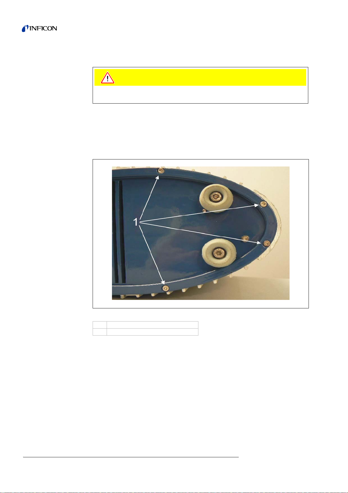
6.3 Replacing the Internal Fuses
Caution
Before opening the housing to replace a fuse, disconnect the T-Guard™ Leak
Detection Sensor from the power supply.
Tools : 3 mm Torx screw driver
Open the housing:
1 Remove 4 screws from the bottom.
68 Maintenance
Fig. 7-4 Bottom view of the T-Guard™ Leak Detection Sensor
Item Description
1 Screws on bottom
jina85e 6.fm Technical Handbook(1112)
Page 71

2 Remove 4 screws from the top.
Fig. 7-5 Top view of the T-Guard™ Leak Detection Sensor
Item Description
1 Screws on top
3 Remove the front cover of the housing.
Fig. 7-6 Open the front part of the housing like the arrow indicates
jina85e 6.fm Technical Handbook(1112)
Now you can see the fuses inside the T-Guard™ Leak Detection Sensor.
Maintenance 69
Page 72

Fig. 7-7 Location of the fuses Digital I/O
70 Maintenance
jina85e 6.fm Technical Handbook(1112)
Page 73

7 Product Handling
Declaration of Contamination
Legally binding declaration:
I/we hereby declare that the information on this form is complete and accurate and that I/we will assume any further costs that may
arise. The contaminated product will be dispatched in accordance with the applicable regulations.
Organization/company
Address Post code, place
Phone Fax
Email
Name
Date and legally binding signature Company stamp
1) or not containing any amount
of hazardous residues that
exceed the permissible ex posure limits
Process related contamination of product:
toxic no 1) yes
caustic no 1) yes
biological hazard no yes 2)
explosive no yes 2)
radioactive no yes 2)
other harmful substances no1) yes
The service, repair, and/or disposal of vacuum equipment and components will only be carried out if a correctly completed declaration has
beensubmitted. Non-completion will result in delay.
This declaration may only be completed (in block letters) and signed by authorized and qualified staff.
Copies:
Original for addressee - 1 copy for accompanying documents - 1 copy for file of sender
Harmful substances, gases and/or by-products
Please list all substances, gases, and by-products which the product may have come into contact with:
Trade/product name
Chemical name
(or symbol)
Precautions associated
with substance
Action if human contact
Description of product
Type
Article Number
Serial Number
Reason for return
Operating fluid(s) used (Must be drained before shipping.)
The product is free of any substances which are damaging to
health yes
This form can be downloaded
from our website.
2) Products thus contami nated will not be ac cepted without written
evidence of decontam i nation!
7.1 Transporting
When transporting the T-Guard™ Leak Detection Sensor, always use the original
box in which it was shipped to you.
7.1.1 Transporting after Contamination
If equipment is returned to INFICON or an authorized INFICON representa tiv e,
indicate whether the equipment is free of substances damaging to health or wheth er
it is contaminated. If it is contaminated, also indicate the nature of the hazard.
INFICON must return any equipment without a Declaration of Contamination to the
sender’s address.
You will find an example of the form below. The appropriate form is attached to the
T-Guard folder.
7.2 Disposal
Fig. 8-1 Sample of form for declaring contamination
When disposing of the T-Guard™ Leak Detection Sensor, co nsider your federal la w
jina85e 7.fm Technical Handbook(1112)
concerning the disposal of electronic devices.
Product Handling 71
Page 74

8 Technical Data
8.1 P ower supply
Supply voltage 24 V DC / 6 A
Typical power consumption < 100 VA
Type of protection IP40
8.2 Weight / dimensions
Dimensions (L x W x H) 258 x 130 x 272 mm
Weight 4.5 kg / 10 lbs
Noise level dB(A) < 56
Noise level dB (A) 0.5 m distance < 56
Contamination level (to IEC 60664-1) 2
Overvoltage category (to IEC 60664-1) II
10.2“ x 5.1“ x 10.7“
8.3 Characteristics
Max. inlet pressure 2000 mbar
Minimum detectable helium leak rate < 1×10
Max. carrier gas flow 1,000,000 sccm
Maximum helium leak rate which can be displayed
Measurement range 5 decades
Time constant of the leak rate signal
(63% of the final value)
gas flow 180 sccm
Gas flow in GROSS mode 90 sccm
Detectable gas Helium
Helium sensor Wise Technology™
Hose connectors 6 mm
Run up time (after starting) 3 - 30 min
Valves Solenoid
Screw thread IN / REF-line 1 / 8’’ M-NPT
Screw threads bottom M 5
-6
mbar l/s
0.1 mbar l/s
<1s
72 Technical Data
jina85e 8.fm Technical Handbook(1112)
Page 75

8.4 Environmental Conditions
For use within buildings
Permissible ambient temperature (during operation) +10° C … +50° C
Permissible storage temperature 0° C … +60° C
Maximum relative humidity 80% at 31°C / 88°F,
Max. permissible height above sea level
(during operation)
8.5 Assembly Drawing for built-in Control Unit
50° F … 122° F
32° F … 140° F
linearly decreasing to
50 % at 40 °C / 104 °F
2000 m
Fig. 9-2
jina85e 8.fm Technical Handbook(1112)
Technical Data 73
Page 76

9 Errors and Warnings
Error No. Plain text message Possible reason Recommendation
Fuse F1 on the DC/DC board has
E1 24 V of the MC50 is too low
E2 24 V of sensor heating too low
E3 24 V II too low
W4 24 V at socket OPTION is too low
E7 -15 V of the MC50 is too low DC/DC board defective
E8 15 V of the MC50 is too low DC/DC board defective
blown or power supply unit too
weak
Fuse F2 on the DC/DC board has
blown or power supply unit too
weak
Fuse F3 on the DC/DC board has
blown or power supply unit too
weak
Fuse F4 on the DC/DC board has
blown or power supply unit too
weak
Replace the Fuse F1 on the DC/
DC board or use a controlled
power supply unit.
Replace the Fuse F2 on the DC/
DC board or use a controlled
power supply unit.
Replace the Fuse F3 on the DC/
DC board or use a controlled
power supply unit.
Replace the Fuse F4 on the DC/
DC board or use a controlled
power supply unit.
Call nearest INFICON service
representative
Call nearest INFICON service
representative
E9 High Voltage error Problem in sensor electronics
T-Guard™ Leak Detection Sensor
possibly not being used for
several days, sensor current
W11 Wise-current unstable
E12 Wise Sensor not ignited
E13 Problem in Heater Control
E14 Discharge gone out
E19 No communication with Wise ADC
E20
E20
Temperature at electronic unit is too
high (>60°)
Temperature at electronic unit is too
high (>60°)
should stabilize after longer runtime.
The helium background is higher
than 20 ppm.
Current from Wise Technology
sensor too low for more than 10
min after power on.
(>5E-11 A).
Heater control for Wise
Technology sensor defective.
Sensitivity problem of Wise
Technology sensor
or
No ambient helium present (e.g.
inlets purged with nitrogen)
Wise Technology sensor defective
or
CPU-board defective
Ambient temperature too high
Ventilation failure
Call nearest INFICON service
representative
Get the T-Guard™ run for 2
hours. Reduce the helium
background in the room.
Restart the T-Guard™ Leak
Detection Sensor, if problem
persists, call nearest INFICON
service representative
Restart the T-Guard™ Leak
Detection Sensor, if problem
persists, call nearest INFICON
service representative
Restart with inlets connected to
external air
If problem persists, call nearest
INFICON service representative
Call nearest INFICON service
representative!
Cool down environment, place
the T-Guard™ Leak Detection
Sensor in cooler area.
Check if fan is (check for air flow
through inlet of the housing)
74 Errors and Warnings
jina85e 9.fm Technical Handbook(1112)
Page 77

Error No. Plain text message Possible reason Recommendation
W28
Real time clock reset! Please enter
date and time!
CPU-board has been replaced Please enter date and time
Battery on CPU-board faulty Replace CPU-board*
Do not switch off the TGuard™ Leak Detection
Sensor
Supply external air through the
sniffer line quickly, restart the TGuard™ Leak Detection Sensor
and wait to allow the T-Guard™
E32 Wise current too high
Wise Technology sensor current
exceeds threshold value
Leak Detection Sensor to
recover!
If problem persists, call nearest
INFICON service representative.
Sensor pressure higher than 800
E38 Pump defect
mbar
Fore pump defect, not switched on
Please check the fore pump.
or pump hose defect
W39 Valve block error!
Cannot recognize valve block
version during self-test
Call nearest INFICON service
representative
Pressure difference between
W41
Pressure difference too high
measuring inlet /air inlet ±10%
Pressure difference between
Check inlet filters
READY and FINE
W43 Pressure too low
W44 Pressure too high
W45 T oo high helium concentration
W50 No I·Stick present.
Pressure below the lower limit.
Reference line plugged
Pressure above the upper limit
Wrong fore pump
Pump hose defect
During the purging process, too
much helium is before or in the
measuring line. T-Guard stops the
purging process too early to
protect the sensor
The test chamber was not purged
sufficiently before the
measurement.
I·Stick was not connected during
running-up.
Check the lower pressure limit
Check the reference line
Check the upper pressure limit
Please check the fore pump and
the pump hose
Purge the chamber with external
air and start a new purging
process of the sensor via the PLC
or the RS232 command,
Purge the test chamber more
thoroughly before
measurements.
Switch the T-Guard off and on
again with the I•Stick connected.
I·Stick defect
W52
Lost I·Stick parameters!
Please check the settings!
I·Stick disconnected during
operation
I·Stick defect
Please check all your settings.
Switch the T-Guard off and on
again with the I•Stick connected.
Restart the T-Guard™ Leak
W59
EEPROM parameter queue
overflow!
May occur when the software has
been updated to an older version.
Detection Sensor, if problem
persists, call nearest INFICON
service representative
W60
All EEPROM parameters are lost!
Please check your settings!
New EEPROM has been installed,
EEPROM on motherboard is
virgin
If message comes up repeatedly
during start-up, EEPROM on
All settings in software menu are
reset to default! Please enter
your settings again
Replace EEPROM*
motherboard is faulty
jina85e 9.fm Technical Handbook(1112)
Errors and Warnings 75
Page 78

Error No. Plain text message Possible reason Recommendation
Software update performed and
new parameters have been
W61 EEPROM parameter initialized!
W62 Lost EEPROM parameters!
introduced
Newly introduced parameters are
listed below warning
If message comes up repeatedly
during start-up, EEPROM on
motherboard is faulty
Parameter has been modified
during software update and reset
to default value
Affected parameters are listed
below warning
If message comes up repeatedly
during start-up, EEPROM on
motherboard is faulty
Acknowledge warning
Replace EEPROM*
Check setting of modified
parameters in corresponding
software menu and set to desired
value
Replace EEPROM*
W64 Th ere are outstanding warnings!
W81 Calibration factor too low!
W82 Calibration factor too high!
Acknowledged but still valid
warnings will be repeated every 2
hours or on each new power on
If the calibration factor was
measured with 0.2, calibration
was not successful. If the
calibration factor was confirmed
between 0.2 and 0.5, a warning
will be output, however, also after
the confirmation of the successful
calibration.
The leak rate of the test leaks is
higher than entered.
If the calibration factor was
measured to be higher than 5,
calibration was not successful. If
the calibration factor was
confirmed between 2 and 5, a
warning will be output, however,
also after the confirmation of the
successful calibration.
Calibration factor during
calibration determined to be > 10
The leak rate of the test leaks is
smaller than entered.
Chamber volume or gas flow are
greater than entered.
Please double-check the
warnings
Check correct setting of test leak
value
Check the settings of the
chamber volume or the gas flow.
Check correct setting of test leak
value
Check the settings of the
chamber volume or the gas flow.
W84 Test leak signal too small
76 Errors and Warnings
Test leak faulty Please check all your settings.
Trigger value(s) too high Check the trigger
Settings of volume/flow too low
Test chamber leaky Check the chamber for tightness
Check the free volume/the carrier
gas flow
jina85e 9.fm Technical Handbook(1112)
Page 79

Error No. Plain text message Possible reason Recommendation
Do not switch off the TGuard™ Leak Detection
Sensor
Keep the T-Guard™ Leak
Detection Sensor running while
providing external air into inlets
until the warning disappears.
If the warning occurs frequently,
W89 Over range!
The T-Guard™ Leak Detection
Sensor is contaminated with
helium.
increase the contamination limit.
Check the helium background,
refer to Info page 2.
Test leak value too high during
external calibration!
Use a smaller test leak for
external calibration
W90 Calibration conditions not met
jina85e 9.fm Technical Handbook(1112)
Errors and Warnings 77
Page 80

10 Service Centers World Wide
Algeria jhj@agramkow.dk India asdash@hotmail.com
Agramkow
Sonderborg
Belarus leakdetection.service@inficon.com Ireland reach.unitedkingdom@inficon.com
INFICON GmbH
Cologne
Belgium leakdetection.service@inficon.com Israel urimark@mark-tec.co.il
INFICON GmbH
Cologne
Brazil fernandoz@prestvacuo.com.br Italy reach.italy@inficon.com
PV Pest Vácuo Ltda.
Santa de Parnaíba
Bulgaria leakdetection.service@inficon.com Japan reach.japan@inficon.com
INFICON GmbH
Cologne
China reach.china@inficon.com Canada reachus@vpcinc.ca
INFICON LTD
Hong Kong
INFICON LTD
Beijing
INFICON LTD
Guangzhou
INFICON LTD
Shanghai
Denmark jhj@agramkow.dk INFICON Ltd.
Agramkow
Sonderborg
Germany leakdetection.service@inficon.com Latvia leakdetection.service@inficon.com
INFICON GmbH
Cologne
Estonia leakdetection.service@inficon.com Lithuania leakdetection.service@inficon.com
INFICON GmbH
Cologne
Finland jhj@agramkow.dk Mexico infoqro@meisa.com
Agramkow
Sonderborg
France Christophe.Zaffanella@oerlikon.com Central America infoqro@meisa.com
OLV France
Orsay
Great Britain and
Northern Ireland
INFICON Ltd.
Blackburn
Tel.: +45 741 236 36
Fax: +45 744 336 46
Tel.: +49 221 56788 112
Fax: +49 221 56788 9112
Tel.: +49 221 56788 112
Fax: +49 221 56788 9112
Tel.: +55 114 154 4888
Fax: +55 114 154 4888
Tel.: +49 221 56788 112
Fax: +49 221 56788 9112
Tel.: +8522862.8863
Fax: +852.2865.6883
Tel.: +86.10.6590.0164
Fax: +86.10.6590.0521
Tel.: +8620.8723.6889
Fax: +86.20.8723.6003
Tel.: +8621.6209.3094
Fax: +86.21.6295.2852
Tel.: +45 741 236 36
Fax: +45 744 336 46
Tel.: +49 221 56788 112
Fax: +49 221 56788 9112
Tel.: +49 221 56788 112
Fax: +49 221 56788 9112
Tel.: +45 741 236 36
Fax: +45 744 336 46
Tel.: +33 476 351 584
Fax: +33 476 351 584
reach.unitedkingdom@inficon.com Netherlands leakdetection.service@inficon.com
Tel.: +44 1254 678 250
Fax: +44 1254 698 577
Dashpute
Mumbai
INFICON Ltd.
Blackburn
Mark Technologies Ltd.
Kiriat Ono
INFICON GmbH
Castelnuovo
INFICON Co. Ltd.
Yokohama
Vacuum Products Canada Inc.
Ontario
Korea reach.korea@inficon.com
INFICON Ltd.
Sungnam
INFICON Ltd.
Suwon City
Cheonan City
INFICON GmbH
Cologne
INFICON GmbH
Cologne
MEISA S.a. de C.V.
Querètaro
MEISA S.a. de C.V.
Querètaro
INFICON GmbH
Cologne
Tel.: +91 22 888 0324
Fax: +91 22 888 0324
Tel.: +44 1254 678 250
Fax: +44 1254 698 577
Tel.: +972 35 34 68 22
Fax: +972 35 34 25 89
Tel.: +39 045 6 40 25 56
Fax: +39 045 6 40 24 21
Tel.: +8145.471.3396
Fax: +81.45.471.3387
Fax: +1 905 672 7704
Fax: +1 905 672 2249
Tel.: +82 312 062 890
Fax: +82 312 063 058
Tel.: +82 312 062 890
Fax: +82 312 063 058
Tel.: +82 312 062 890
Fax: +82 312 063 058
Tel.: +49 221 56788 112
Fax: +49 221 56788 9112
Tel.: +49 221 56788 112
Fax: +49 221 56788 9112
Tel.: +52 442 225 42 80
Fax: +52 442 225 41 57
Tel.: +52 442 225 42 80
Fax: +52 442 225 41 57
Tel.: +49 221 56788 112
Fax: +49 221 56788 9112
78 Service Centers World Wide
jina85e 10.fm Technical Handbook(1112)
Page 81

Norway jhj@agramkow.dk Syria leakdetection.service@inficon.com
Agramkow
Sonderborg
Tel.: +45 741 236 36
Fax: +45 744 336 46
INFICON GmbH
Cologne
Tel.: +49 221 56788 112
Fax: +49 221 56788 9112
Poland kamola@vakpol.com Taiwan reach.taiwan@inficon.com
VAK-POL & GAZ Sp. z
Pulawy
Tel.: +48 602 315 212
Fax: +48 602 315 212
INFICON Company Limited
Chupei City, HsinChu Hsien
Tel.: +8863.5525.828
Fax: +886.3.5525.829
Portugal leakdetection.service@inficon.com Czech Republic filip.lisec@inficon.com
INFICON GmbH
Cologne
Tel.: +49 221 56788 112
Fax: +49 221 56788 9112
INFICON GmbH
Pilsen
Tel.: +420 734 331 758
Fax: +420 604 203 037
Republic of South Africa vacuquip@hotmail.com Turkey jhj@agramkow.dk
Vacuquip
Randburg
Tel.: +27 731 578 355 Agramkow
Sonderborg
Tel.: +45 741 236 36
Fax: +45 744 336 46
Russia leakdetection.service@inficon.com Tunisia leakdetection.service@inficon.com
INFICON GmbH
Cologne
Tel.: +49 221 56788 112
Fax: +49 221 56788 9112
INFICON GmbH
Cologne
Tel.: +49 221 56788 112
Fax: +49 221 56788 9112
Sweden jhj@agramkow.dk USA service.usa@inficon.com
Agramkow
Sonderborg
Singapore reach.singapore@inficon.com Inficon Inc.
INFICON PTE LTD.
Singapore
Tel.: +45 741 236 36
Fax: +45 744 336 46
Tel.: +65,890.6250
Fax: +65,890.6266
Inficon Inc.
East Syracuse, NY
San Jose, CA
Inficon Inc.
Austin, TX
Tel.: +1,315,434.1167
Fax: +1.315.434.2551
Tel.: +1.408.361.1200
Fax: +1.408.362.1556
Tel.: +1,512,448.0488
Fax: +1,512,448.0398
Slovakia filip.lisec@inficon.com Ukraine leakdetection.service@inficon.com
INFICON GmbH
Pilsen
Tel.: +420 734 331 758
Fax: +420 604 203 037
INFICON GmbH
Cologne
Tel.: +49 221 56788 112
Fax: +49 221 56788 9112
Slovenia medivak@siol.net Hungary adam.lovic@kon-trade.hu
Medivac
Ljubljana
Spain jordi.poza@leyboldoptics.com United Arab
Tel.: +386 15 63 91 50
Fax: +386 17 22 04 51
Kon-trade + KFT
Budaörs
Tel.: +36 23 50 38 80
Fax: +36 23 50 38 96
leakdetection.service@inficon.com
Emirates
Leybold Optics Ibérica
Barcelona
South America except
Tel.: +34 93 66 60 778
Fax: +34 93 66 64 612
INFICON GmbH
Cologne
Tel.: +49 221 56788 112
Fax: +49 221 56788 9112
infoqro@meisa.com Belarus leakdetection.service@inficon.com
Brazil
MEISA S.a. de C.V.
Mexico
Tel.: +52 44 22 25 42 80
Fax: +52 44 22 25 41 57
INFICON GmbH
Cologne
Tel.: +49 221 56788 112
Fax: +49 221 56788 9112
jina85e 10.fm Technical Handbook(1112)
Service Centers World Wide 79
Page 82

10.1 Ordering Information
Description Cat. no.
T-Guard™ Leak Detection Sensor 540-001
T-Guard™ Leak Detection Sensor, version Profibus 540-002
Control Unit for Desktop Operation 551-100
Control unit for the installation in a 19"-Rack 551-101
Connecting cable for the control unit, 5 m 551-102
Connecting cable for the control unit, 1 m 551-103
Set of connectors 551-110
I•Stick 200 001 997
Set of fuses 200 002 489
Set of filters 200 001 680
I/O test box 200 002 490
Power supply connection 200 002 496
Chamber connector 200 002 615
Measuring line 210 x 2 x 2 m 200 002 793
Fore pump, 24 V, two-step, brushless 200 002 929
80 Service Centers World Wide
jina85e 10.fm Technical Handbook(1112)
Page 83

jina85e 10.fm Technical Handbook(1112)
Service Centers World Wide 81
Page 84

Index
A
Accessories 20
B
Body 9
C
Calibrating 41
Calibration, starting 42
Carrier gas 46
Connecting
•PLC 32
• the Control Unit 30
Connecting a
•PC 38
Connecting a PC 38
Connection Cable 23
Control panel
• Tabletop 20
Cycle time 58
L
LED 12
M
Measuring 43
Measuring time 58
MENU button 21
Menu structure 54
O
Ordering Information 27, 80
P
Parameter set 40, 53, 60
Preparing
• Calibration 41
Purge 58
R
RS232 60
Running up 39
E
Enter the Menu-PIN 22
Error No. 74
F
F.A.Q. - Frequently asked questions 63
Fore Pump 30
H
Hauptmenü 56
I
Installation
• electrical 31
• mechanically 29
Interfaces 10
I-Stick 11
K
Kalibrierung 57
S
Scope of delivery 26
Sensitivity 17, 74
Service Centers 78
Settings 54
Soft Keys 21
Standby 50, 56
START
• button 20
STOP
• button 21
Switching Off 50
T
T-Guard 7, 57
Trigger 56
Z
Zero 20
T-Guard EN_jina85SIX.fm Tech ni ca l Handbook(1112)
Index A
Page 85

INFICON GmbH, Bonner Strasse 498, D-50968 Cologne, Germany
UNITED STATES TAIWAN JAPAN KOREA SINGAPORE GERMANY FRANCE UNITED KINGDOM HONG KONG
Visit our website for contact information and o ther sales offices worldwide. www.inficon.com
Dokument: jina85e1-f (1112)
 Loading...