

Page 1
T3000
Thermal Power Supply
OVER TEMP
POWER MODE
RESET
OPEN
LOAD
SER - PAR
J1
1
OUT 1 NEG
OUT 1 POS
OUT 2 POS
OUT 2 NEG
User's Manual
518-035 Revision A, Feb 2006
Page 2

instruments
Thermal Power Supply
T3000
Preface
Warranty
SYCON INSTRUMENTS, INC.
Policy
Sycon Instruments, Inc. (Sycon) warrants that all electronic instrumentation
equipment manufactured by Sycon shall be free from defects in materials and workmanship
for a period of 2 years from date of shipment. Mechanical vacuum components such as
feedthroughs, sensors, cables, and shutters shall be warranted for a period of six months
from the date of shipment. For the duration of the warranty period Sycon will, at its option,
either repair or replace any part which is defective in materials or workmanship without
charge to the purchaser. The foregoing shall constitute the exclusive and sole remedy of
the purchaser for any breach by Sycon of this warranty.
This warranty does not apply to any equipment which has not been used in
accordance with the specifications recommended by Sycon for the proper and normal use
of the equipment. Sycon shall not be liable under any circumstances for consequential or
incidental damages in connection with, or arising out of the sale, performance, or use of,
the equipment covered by this warranty.
This warranty is in lieu of all other warranties by Sycon, expressed or implied,
including the implied warranty of merchantability, the implied warranty of fitness for a
particular purpose, and warranty against infringement of any patent.
EQUIPMENT RETURN
Before returning any equipment to Sycon contact the Product Service Department in
your area for instructions. Obtain a Return Authorization (RA) number and indicate this
number on all shipping cartons and correspondence. Ship all items in suitable containers
with adequate protection from outside damage.
Sycon Instruments, Inc.
6757 Kinne Street
East Syracuse, New York
13057-1215
Phone (315) 463-5297
Fax (315) 463-5298
Preface
Page i
Warranty
Page 3

T3000
Thermal Power Supply
instruments
Warranty
Page ii
Preface
Page 4

instruments
Thermal Power Supply
T3000
Table of Contents
PREFACE.....................................................................................................................................I
WARRANTY ......................................................................................................................................I
TABLE OF CONTENTS .......................................................................................................................III
LIST OF TABLES ...............................................................................................................................IV
LIST OF FIGURES..............................................................................................................................V
SECTION 1...................................................................................................................................1-1
INTRODUCTION – DESCRIPTION OF EQUIPMENT .................................................................................1-1
1.1 Purpose and Capabilities .............................................................................................1-1
1.2 Theory of Operation .....................................................................................................1-1
1.3 Technical Characteristics.............................................................................................1-2
1.4 Output Characteristics..................................................................................................1-3
SECTION 2...................................................................................................................................2-1
INSTALLATION ..................................................................................................................................2-1
2.1 Inspection.....................................................................................................................2-1
2.2 Input/Output Connectors..............................................................................................2-1
2.3 Locations and Mounting...............................................................................................2-8
2.4 Wire Sizing...................................................................................................................2-9
2.5 Outline Drawings........................................................................................................2-10
SECTION 3...................................................................................................................................3-1
OPERATING INSTRUCTIONS...............................................................................................................3-1
3.1 Controls and Indicators ................................................................................................3-1
3.2 Basic Operation............................................................................................................3-4
SECTION 4...................................................................................................................................4-1
USE OF THE T3000 WITH THE RS-3000.............................................................................................4-1
4.1 Introduction...................................................................................................................4-1
4.2 Description ...................................................................................................................4-1
4.3 Basic Operation............................................................................................................4-5
4.4 Error Conditions ...........................................................................................................4-6
SECTION 5...................................................................................................................................5-1
CALIBRATION ...................................................................................................................................5-1
5.1 Instructions...................................................................................................................5-1
SECTION 6...................................................................................................................................6-1
MAINTENANCE..................................................................................................................................6-1
6.1 Introduction...................................................................................................................6-1
6.2 Preventive Maintenance...............................................................................................6-1
6.3 Fuses............................................................................................................................6-3
SECTION 7...................................................................................................................................7-1
T3000 CONFIGURATIONS..................................................................................................................7-1
7.1 T3000 Stand-Alone Configuration................................................................................7-1
7.2 T3000 Controlled by RS3000.......................................................................................7-2
7.3 T3000 Controlled by STC.............................................................................................7-3
7.4 T3000 Controlled by STC via RS3000........................................................................7-4
APPENDIX A.................................................................................................................................A-1
RMS RELATIONSHIPS.......................................................................................................................A-1
Preface
Page iii
Table of Contents
Page 5

T3000
Thermal Power Supply
instruments
List of Tables
Table 1-1 Specifications .........................................................................................................................1-2
Table 2.2-1 T3000 External Connections...............................................................................................2-1
Table 2.2-2 T3000 Connection Interface................................................................................................2-2
Table 2.4-1 Minimum Wire Size Table ...................................................................................................2-9
Table 3.1-1 T3000 Indicator and Control Description.............................................................................3-1
Table 3.1-2 T3000 LED Mode Indication Summary...............................................................................3-2
Table 3.2-1 T3000 Connector J1 Pin Assignments................................................................................3-5
Table 6-1 Preventive Maintenance Schedule.........................................................................................6-1
Table 6-2 Inspection and Corrective Action............................................................................................6-2
Table A-1 Harmonic Levels & RMS Estimate Error............................................................................... A-2
List of Tables
Page iv
Preface
Page 6

instruments
Thermal Power Supply
T3000
List of Figures
Figure 1-1 Maximum Voltage-Current Profile for Series and Parallel Hookup........................................ 1-3
Figure 2.2-1 AC Line and Frame Ground Connections.............................................................................. 2-4
Figure 2.2-2 Bus Bar Identification For The Two Output Sections............................................................. 2-5
Figure 2.2-3 Bus Bar Jumpers Connect Two Output Sections In Parallel ................................................. 2-6
Figure 2.2-4 J-Shaped Bus Bar Connects Two Supply Sections in Series................................................2-7
Figure 2.3-1 Location of Six Mounting Holes on T3000 Side Panels......................................................... 2-8
Figure 2.3-2 Side-By-Side19” Rack Mount Configuration.......................................................................... 2-8
Figure 2.5-1 T3000 Case Outline Drawing............................................................................................... 2-10
Figure 3.1-1 LED and Reset Button Location: Back Panel View ............................................................... 3-3
Figure 3.2-1 Various Methods For Controlling The T3000 Power Supply..................................................3-4
Figure 4.2-2: RS-3000 Front Panel .............................................................................................................4-3
Figure 4.2-2 RS-3000 Back Panel..............................................................................................................4-4
Figure A-1 Full-Wave Rectified SIN[2π60t]..............................................................................................A-1
Figure A-2 Current Transformer Method for Estimating True RMS Value of Io from AC Current
Components Measurement ..........................................................................................................................A-3
Preface
Page v
List of Figures
Page 7

T3000
Thermal Power Supply
instruments
List of Figures
Page vi
Preface
Page 8

instruments
Thermal Power Supply
T3000
Section 1
Introduction – Description of Equipment
1.1 Purpose and Capabilities
The Sycon T3000 is designed specifically to power resistive evaporative sources used in
the deposition of thin film coatings. It has been specified to cover the class of resistive load
devices requiring low voltage and high current at power levels up to 3kW. The two output
sections of the supply can be connected in parallel to provide up to 600 Amperes RMS in
excess of 5 Volts, or in the series connected configuration, 300 Amperes RMS in excess of
10 Volts. This versatile output range covers a broad spectrum of thermal sources. T3000
power supplies can be connected in parallel to meet extremely high power requirements,
(two units connected in parallel would provide up to 6kW load power.)
Several methods for controlling output power are available to the user. In the simplest
arrangement, a user-supplied DC voltage is applied to control the output current to the
load. A current feedback loop in the T3000 serves to stabilize output load current in
proportion to this DC control voltage input.
The next level of sophistication is to use the T3000 in conjunction with the Sycon RS3000
controller. This unit allows the user to input desired current levels with corresponding rate
of rise times to control load thermal stresses and to monitor set points and output power
levels. The controller features automatic shutdown to govern over-temperature and openload failure modes.
The T3000 is also directly compatible for use with industry standard thickness/rate
controllers, such as the Sycon STC-200 or STC-2000 products. This configuration allows
setting of specified deposition rates through automatic control of output power to the
thermal source. STC PID control loop features govern deposition dynamics for these
applications.
The most sophisticated configuration employs the T3000 with the RS3000 and STC-200 or
STC-2000 products. This configuration allows setting of specified deposition rates through
automatic control of output power to the thermal source, control of PID loop dynamics and
provides set points and output power level as well as other monitoring and control
functions.
1.2 Theory of Operation
The T3000 is a switch mode power supply (SMPS), which operates at a switching
frequency of 250kHz. High frequency operation allows significant reduction in the size and
weight of the magnetic components while maintaining high operating efficiency.
The SMPS converts 208/220 VAC single-phase line voltage to a line-isolated full-wave
rectified 120-Hertz output waveform, which provides up to 3kW output power. Please note
that the RMS value of a full-wave rectified sine wave is the same as that of the sine wave,
Section 1
Page 1 - 1
Introduction – Description
of Equipment
Page 9

T3000
Thermal Power Supply
instruments
although it contains both DC and harmonics of line frequency. Therefore, the heating value
in the load (the resistive deposition source) is the same whether the current is sine wave,
rectified sine wave or a DC voltage all of equal RMS value.
The rectified line frequency was chosen as the output format because it offers an inherent
unity power factor characteristic for the power supply. This comes about because power is
being delivered to the resistive load throughout the 60-Hertz cycle of line frequency. Since
conversion from line to output is performed at 250 kHz, there is insignificant phase shift
introduced at the 60-Hertz line frequency. The net result is input line current that is, ideally,
sinusoidal and essentially in-phase with the line voltage. This is the condition for near unity
power factor.
1.3 Technical Characteristics
Table 1-1 Specifications
Output Power 3000 Watts
Parallel Output 5 Volts @ 600 Amps RMS
Series Output 10 Volts @ 300 Amps RMS
Input Voltage Range 180-264 VAC, Single Phase
Input Freq. Range 47 Hz to 63 Hz
Input Current 18 Amps @ 220 VAC
Efficiency 80% Full Load
Power Factor >0.99 @ Full Load (TBD)
Total Harmonics < 5% @ Full Load (TBD)
Input Control 0 to +10VDC Required For Controlling Output Current
Response Time <100ms 250A to 500A Step Parallel Output
1
Current Monitor 1 VDC = 100 Amps RMS For Parallel & 50 Amps For Series
Voltage Monitor 1 VDC = 1.5 Volt RMS Across Output Terminals
Protection Over Temperature Shutdown
Size 11.4 in. H x 5.25 in. W x 12.9 in. D
Power Density 4 Watts per cubic inch
Weight 28 Pounds
Ambient Range 0oC to +50oC at full load
Cooling Forced air, two internal fans
EMI Designed to meet Conducted and Radiated EN55022
Safety Designed to meet EN60950
Output Connectors Flat bus bars with ¼” Bolt Hole for Lug Attachment
AC Input Wiring 2-Wire plus Ground with 8 – 32 lugs
I/O Connector 15-pin Dsub for control, monitoring and status signals
Power ON Indicator Green LED: Flashing=Input Power ON, Steady=Output ON
Over Temperature Red LED: Steady=Over Temp, Flashing=Ready for Reset
Open Load Red LED: Steady=Open Load
Compatibility Sycon Controller RS3000 &/or Rate Deposition Controllers
Footnote1; Response time is load dependent with lower resistance loads exhibiting faster response.
Introduction – Description
of Equipment
Page 1 - 2
Section 1
Page 10
instruments
Thermal Power Supply
T3000
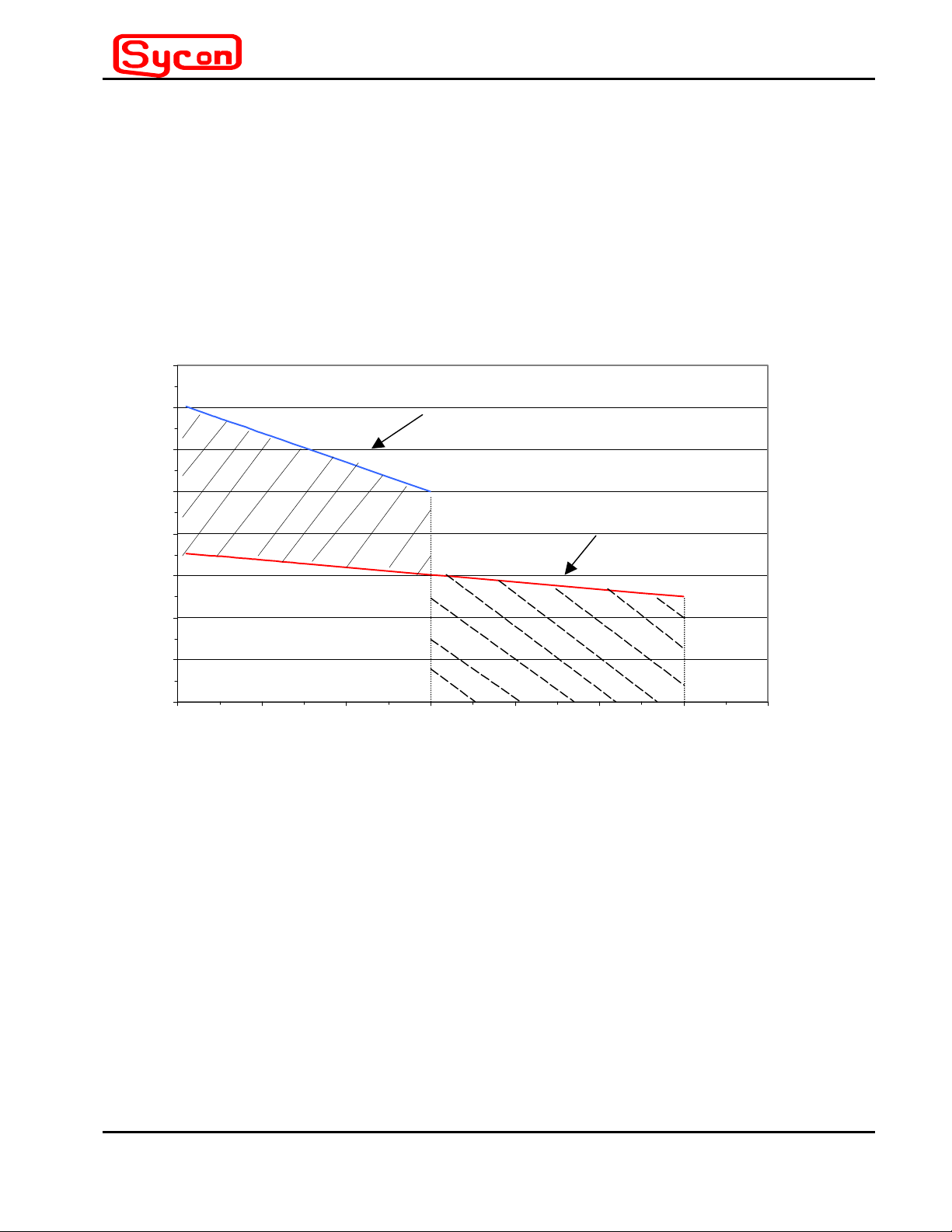
1.4 Output Characteristics
The purpose of this subsection is to provide guidelines for choosing between series or
parallel output connections based on the load requirements of the thermal source being
energized. Output voltage and current profiles vary in proportion to load resistance, up to
maximum limits determined by the output circuit configuration. Figure 1-1 provides a
guideline for choosing the appropriate output hookup configuration, based on the T3000
maximum output profile and the load requirements of the thermal source.
Maximum Load Vol t age- Cur r ent Pr of ile
16
14
12
Series Only Regi on
10
8
6
Load Voltage - Volts RMS
4
2
0
0 100 200 300 400 500 600 700
Max Output: Series Configuration
Vline = 220V rms
Max Output: Parallel Confi gur at ion
Parallel Region OnlyEither Seri es or Pa rallel Regi o n
Load Current - Am ps RMS
Figure 1-1 Maximum Voltage-Current Profile for Series and Parallel Hookup
Figure 1-1 is marked with regions which define when the series or parallel output
configuration is appropriate. The maximum voltage-current rating of any given thermal
source may be located as a point on the graph. The appropriate configuration(s) is
determined by the location of this point.
For example, consider a commercially available thermal source rated at 521 ARMS and a
corresponding voltage drop of 3.89 VRMS. This is a 2kW thermal source and falls in the
area of the graph noted as “Parallel Only”.
By way of contrast, a thermal source rated at 742 Watts, which is specified by a voltage
drop of 8.73 VRMS at 85 ARMS and falls in the “Series Only” region of the graph.
Section 1
Page 1 - 3
Introduction – Description
of Equipment
Page 11

T3000
Thermal Power Supply
instruments
As a third example, consider a thermal source rated at about 365 Watts exhibiting a voltage
drop of 1.34V at a maximum current of 273 Amperes. This falls in the region where either a
series or parallel connection would work.
The above sample calculations assume that the voltage drop in the wires connecting to the
T3000 is small in comparison to the voltage drop across the thermal source load. This
condition is usually satisfied when the output wiring is properly sized for current carrying
capacity.
Generally, where either a series or parallel option is available, the series configuration is
recommended.
Introduction – Description
of Equipment
Page 1 - 4
Section 1
Page 12
instruments
Thermal Power Supply
T3000
Section 2
Installation
2.1 Inspection
Inspect the shipping carton for possible damage before unpacking the unit. Carefully
unpack the equipment. Save all packing materials until inspection is complete. Verify that
all items listed on the packing slips have been received. Visually inspect all exterior
surfaces for damage. External damage may be an indication of internal damage. If any
damage is evident, immediately contact the carrier that delivered the unit and submit a
damage report. Failure to do so could invalidate future claims.
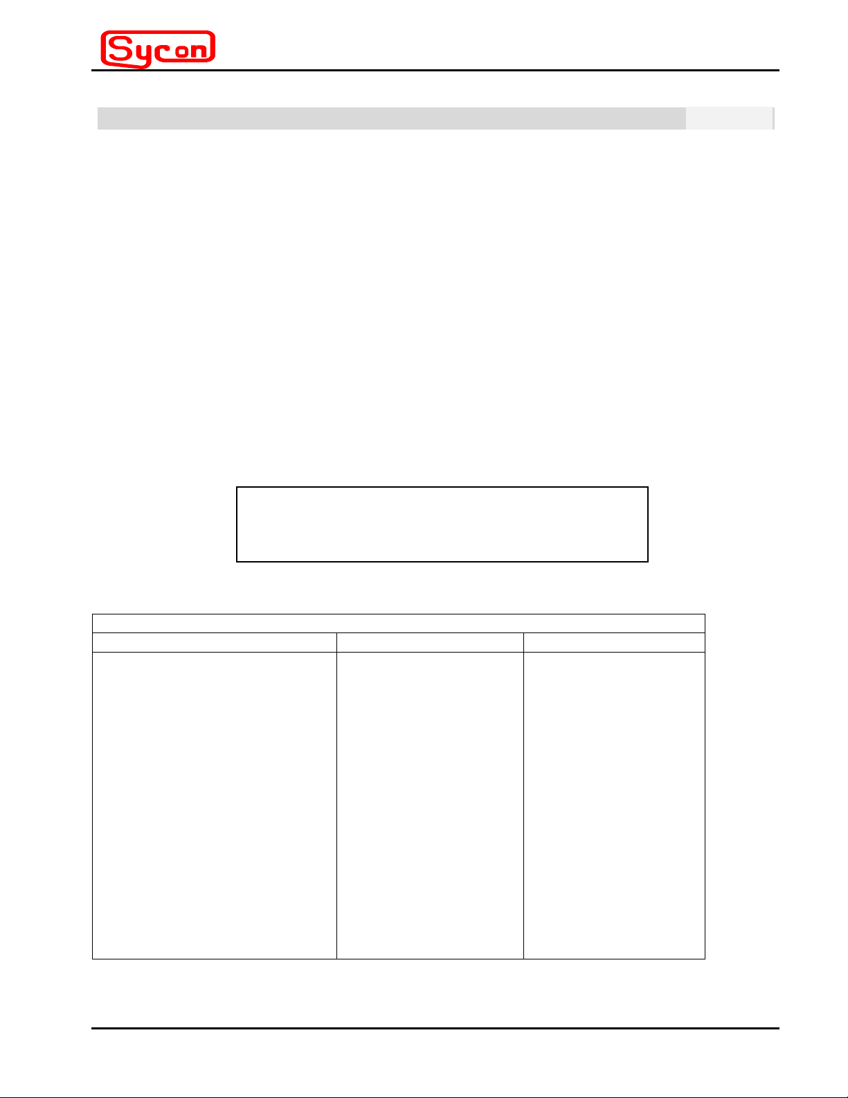
2.2 Input/Output Connectors
Table 2.2-1 lists all external connections for the T3000. An input and output connector
description is provided in Table 2.2-2. For permanently connected equipment, a readily
accessible safety switch shall be incorporated in the fixed AC wiring.
Table 2.2-1 T3000 External Connections
CONNECTOR FUNCTION CONNECTS TO
AC1 (See Figure 2.2-1)
AC2
Frame Ground
Section 1 (See Figure 2.2-2)
Positive Bus Bar
Negative Bus Bar
Section 2 (See Figure 2.2-2)
Positive Bus Bar
Negative Bus Bar
J1
For proper connection to the mains, a 30-Amp circuit
breaker or fuse is required in each AC line.
Prime AC Power Input
Single Phase
Output Power
Output Power
Control Interface
NOTICE
180-264 VAC
47-63 Hertz
Power Source
User Load
(See Figure 2.2-3 for
series or parallel
connections)
User Load
See Table 3.2-1
Section 2
Page 2 - 1
Installation
Page 13
T3000
Table 2.2-2 T3000 Connection Interface
Connector Function Description
AC line connections & frame ground
Output Bus Bars
J1 control interface
Figure 2.2-1 shows the location and connection configuration for the single AC line input
(180-264 VAC). The AC wiring should be terminated with NO. 8 ring terminals and secured
to the 8-32 male terminals on the T3000 with nut and lock-washer. A safety cover, with
strain relief, covers the AC input connections.
Thermal Power Supply
8-32 Threaded Stand-off accepts #8
Ring terminal
¼” bolt holes
15 pin DB female (accepts 15 pin male
matching connector on cable)
instruments
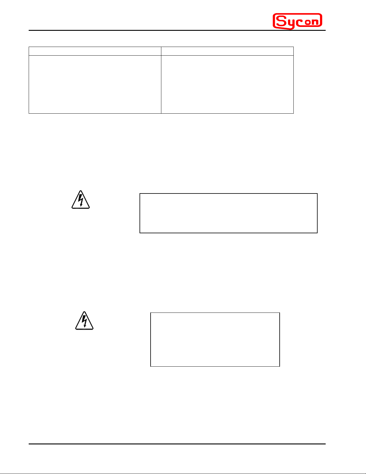
CAUTION
Hazardous
Voltages
Present
Figure 2.2-2 shows the location of the bus bars for the two output sections and defines the
polarity relative to each other. Note that the Output-2 positive bus bar is common with the
T3000 signal ground.
TURN OFF THE INPUT AC POWER WITH THE
SAFETY SWITCH BEFORE REMOVING THE
T3000 PROTECTIVE COVER.
Hazardous
Current
Levels
Possible
Figure 2.2-3 shows how the auxiliary C-shaped and flat bus bars are utilized to connect the
two output sections of the T3000 in the parallel configuration. Cables to the thermal
sources (usually the feedthrough terminals of the vacuum chamber) must be terminated in
a suitably current rated solderless connector with a ¼-inch bolt hole for connection to the
bus bars.
Installation
TURN OFF THE INPUT AC POWER
WITH THE SAFETY SWITCH
BEFORE CHANGING
CONNECTIONS TO BUS BARS.
Page 2 - 2
CAUTION
Section 2
Page 14

instruments
Thermal Power Supply
T3000
Figure 2.2-4 shows a similar arrangement for series connection of the two output sections
using the auxiliary Z-shaped bus bar. Cable connection requirements must be consistent
with current load requirements.
Also shown in Figure 2.2-4 is the location of the DB15 connector, which interfaces with the
control cable from the RS3000 or other user specified control hardware.
Section 2
Page 2 - 3
Installation
Page 15

T3000
Thermal Power Supply
instruments
Frame Ground
8-32 Male Standoff
AC line Inputs
8-32 Male
OVER TEMP
POWER MODE
RESET
OPEN
LOAD
SER - PAR
J1
1
Rear Panel
Cutout with
Protective Cover
Removed
OUT 1 NEG
OUT 1 POS
OUT 2 POS
OUT 2 NEG
Figure 2.2-1 AC Line and Frame Ground Connections
(Shown with safety cover removed to expose terminals)
Installation
Page 2 - 4
Section 2
Page 16

instruments
Thermal Power Supply
T3000
Out-1 Pos.
Bus Bar
OVER TEMP
POWER MODE
RESET
OPEN
LOAD
SER - PAR
J1
1
Out-2 Pos.
Bus Bar
(Signal
Ground)
Out-1 Neg.
Bus Bar
OUT 1 NEG
OUT 1 POS
OUT 2 NEG
Out-2 Neg.
Bus Bar
OUT 2 POS
Figure 2.2-2 Bus Bar Identification For The Two Output Sections
Section 2
Page 2 - 5
Installation
Page 17

T3000
Thermal Power Supply
instruments
OVER TEMP
POWER MODE
RESET
OPEN
LOAD
SER - PAR
J1
1
OUT 1 NEG
OUT 1 POS
Figure 2.2-3 Bus Bar Jumpers Connect Two Output Sections In Parallel
Installation
Page 2 - 6
Section 2
Page 18

instruments
Thermal Power Supply
T3000
DB15 Female
Connector For Control
Signal Interface Cable
Neg Cable to Load
Connected By Nut,
Bolt, Washer and
Lock-Washer
Pos. Cable to
Load Connected
By Nut, Bolt,
Washers and
Lock-Washers
Figure 2.2-4 J-Shaped Bus Bar Connects Two Supply Sections in Series
J-Shaped Bus
Bar Connects
Two Output
Sections in
Series
Section 2
Page 2 - 7
Installation
Page 19

T3000
Thermal Power Supply
instruments
2.3 Locations and Mounting
There are six #10-32 threaded mounting holes on each side of the T3000 that can be used
for custom mounting the unit. It is recommended that the unit be located as close as
possible to the vacuum chamber electrical feedthroughs, in order to minimize cable losses
for the high current connections. Locations for these mounting holes are shown in the
outline drawing of Figure 2.3-1.
Figure 2.3-1 Location of Six Mounting Holes on T3000 Side Panels
The T3000 power supply and the RS3000 controller are also designed to mount in a
standard 19.0-inch equipment rack using a custom front panel. The panel contains a power
ON/OFF switch with a built-in circuit breaker. The panel and switch are available from
Sycon Instruments. Four screws, two on each side of the front panel, should be used to
secure the unit in place. Figure 2.3-2 shows the mechanical arrangement for side-by-side
rack mounting of the two units.
Power ON/OFF Switch
T3000 RS3000
Installation
Figure 2.3-2 Side-By-Side19” Rack Mount Configuration
Page 2 - 8
Section 2
Page 20

instruments
Thermal Power Supply
T3000
NOTICE
The front and rear of the unit should be free of obstructions to airflow. Proper ventilation
must be maintained, regardless of mounting or orientation.
2.4 Wire Sizing
Care must be taken to properly size all conductors for the input and output of the power
supply. Table 2.4-1 gives minimum recommended wire size for different current levels and
operating temperatures. This table is derived from the National Electrical Code and is for
reference only. Local laws and conditions may have different requirements. The table is for
copper wire only.
Table 2.4-1 Minimum Wire Size Table
COPPER WIRE CURRENT CAPACITY
Single wire in open air, ambient temperature 86
o
F
Ampacities of Wire Types (w/ Temp Rating) @ 0-2000 Volts
USE-2, XHH, XHHW, -2, TA,
TBS, SA, SIS, FEP
Wire
Size
AWG
0000
000
00
0
1
2
3
4
TW
UF
(140oF)
300
260
225
195
165
140
120
105
FEPW, RH, RHW, THW,
THWN, ZW,
THHW, XHHW
(167oF)
360
310
265
230
195
170
145
125
MI, RHW-2, THHN, ZW-2,
THWN-2, FEPB, RHH,
THHW, THW-2
(194oF)
405
350
300
260
220
190
165
140
Section 2
Ambient Ampacity Correction for above Wire types
Temp oF 140
96-104
105-113
114-122
123-131
132-140
141-158
159-176
o
F 167
0.82
0.71
0.58
0.41
- - -
- - -
- - -
Page 2 - 9
0.88
0.82
0.75
0.67
0.58
0.35
o
F 194
- - -
0.91
0.87
0.82
0.76
0.71
0.58
0.41
o
F
Installation
Page 21

T3000
Thermal Power Supply
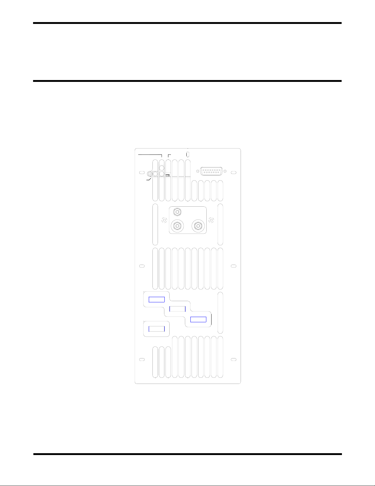
2.5 Outline Drawings
Figure 2.5-1 shows the outline drawing for the T3000 power supply.
instruments
Installation
Figure 2.5-1 T3000 Case Outline Drawing
Page 2 - 10
Section 2
Page 22

instruments
Thermal Power Supply
T3000
Section 3
Operating Instructions
3.1 Controls and Indicators
The T3000 has been designed with few user interface requirements, since primary usage
will be in conjunction with the Sycon RS3000 controller and/or rate deposition controllers,
such as the Sycon STC200 or STC2000. Stand-alone usage is also permissible and only
requires a user supplied control voltage, 0 to +10 Volts, on J1 pin 7 with ground return on
pins 3 and 11 and a external on/off switch between pins 13 and 11 on J1. The power
supply has three LEDs which monitor operation, and a user accessible reset button to
reestablish output power after fault removal. These items are beneficial for monitoring
power supply operation in any usage configuration. The T3000 also has a Series/Parallel
Mode Switch which is intended for use only in conjunction with the RS3000. These
functions are delineated in Table 3.1-1.
Table 3.1-1 T3000 Indicator and Control Description
Indicator or Control Item Usage Description
Green LED: Power Indicator
Red LED: Over-Temperature Fault
Blinks at a regular rate to indicate AC line power is
ON and the supply is in a standby mode. When load
power is enabled, by shorting J1-pin 13 to pin 3 or
11, the supply is in the active state and the LED
emits a constant glow, provided no faults exist.
This LED will glow steadily when power supply
internal temperatures are excessive, causing a
safety shutdown of output power. (A primary cause
could be airflow blockage due to improper installation
of the power supply in the user environment). The
LEDs will blink at a constant rate when the internal
temperature has cooled to a safe operating point.
The reset button can then restore T3000 operation.
Red LED: Open load condition This LED will glow steadily when the load connection
is open, a condition that causes the power supply to
automatically shutdown.
Reset Button Switch: Primarily intended to
allow recovery after an internal
temperature fault
Series / Parallel Mode Switch: Intended
for use only in conjunction with the
RS3000
In addition, after AC line voltage is turned on, the green LED and the red over-temperature LED will
blink sequentially once per second for eight seconds. The unique series of red and green blinks
correspond to identify the version of firmware programmed in the unit. For example, a blinking
sequence of R,R,R,R,R,R,G,G defines a particular firmware code. Sycon technical support
Section 3
After cool-down, output power to the load can be
reestablished with the reset button. It can also be
used to verify the open load condition by attempting
to recycle power to the load.
The position of this switch must be manually set to
match the output configuration of the T3000. Switch
position is decoded by the RS3000 Controller to set
correct scale factors for each mode.
Page 3 - 1
Operating Instructions
Page 23

T3000
Thermal Power Supply
instruments
personnel may request this information, when service calls are made to the factory.
Table 3.1-2 summarizes the different modes associated with the three LED’s.
Table 3.1-2 T3000 LED Mode Indication Summary
Start-up
Timing
Seconds
Power ON
Indicator
Green LED
Internal
Over
Temperature
Open Load
Condition
Red LED
Condition
Red LED
0 to 1 Steady Glow Steady Glow Steady Glow LED Checkout
1 to 9 Blink in sequence per
Steady Glow Denotes Firmware Version
version code
After Start
Sequence is
completed
Blink
once/sec
Steady Glow Dark Dark Output Power Enabled -
Dark Dark Ready for output power
Enable
Operational
Blink
once/sec
Blink
once/sec
Blink
once/sec
Figure 3.1-1 shows the location of the three LEDs and push-button reset switch on the rear panel of
the T3000.
Dark Steady Glow Open Load; Output Power
Inhibited
Steady Glow Dark Over Temp; Output Power
Inhibited
Blinks
twice/sec
Dark Cooled down; Ready for
reset
Section 3
Page 3 - 2
Section 3
Page 24

instruments
Thermal Power Supply
T3000
Reset Push
Button
Thermal
Source Status
Red LED
Power Mode
Green LED
OVER TEMP
POWER MODE
RESET
OPEN
LOAD
SER - PAR
J1
1
Internal
Temperature
Status Red LED
Series/Parallel
Slide Switch
OUT 1 NEG
OUT 1 POS
OUT 2 POS
OUT 2 NEG
Figure 3.1-1 LED and Reset Button Location: Back Panel View
Section 3
Page 3 - 3
Operating Instructions
Page 25

T3000
Thermal Power Supply
instruments
3.2 Basic Operation
The T3000 can be used in several control configurations as depicted by the block diagrams of
Figure 3.2-1.
Vcontrol
0 - +10V
OFF/ON
Momentary
RS3000
Pin 7
Pin 13
To Multimeter Imon Pin 15
To Multimeter Vmon Pin 4
Ex ternal Fault Rest Pin 5
Pins 3 & 11
PBS
Cable
J1
J1
T3000
STAND ALONE
CONFIGURATION
T3000
CONTROLLED
STC
RS3000
For External Monitoring
To Multimeter Imon Pin 15
To Multimeter Vmon Pin 4
External Fault Rest Pin 5
Signal Ground Pins 3 & 11
Custom Split Cable
Cable
Cable
BY RS3000
J1
T3000
CONTROLLED
BY STC
J1
T3000
CONTROLLED BY
STC VIA RS3000
Figure 3.2-1 Various Methods For Controlling The T3000 Power Supply
Section 3
STC
Page 3 - 4
Section 3
Page 26

instruments
Thermal Power Supply
T3000
Table 3.2-1 shows the function of each pin for connector J1 where control and monitor
signals interface with the unit.
Table 3.2-1 T3000 Connector J1 Pin Assignments
PIN NUMBER PIN FUNCTION
1 Open Boat Output High
2 +5 VDC Out
3 Signal Ground
4 Output Voltage Monitor 1VDC = 1.5VRMS
5 External Reset
6 No Connection
7 Current Set Point Control Voltage
8 No Connection
9 Over Temperature Output High
10 +5 VDC
11 Signal Ground
12 + 12 VDC Out
13 Output Load Power On When Low
14 Series / Parallel Select
15 Current Monitor 1VDC =100ARMS Parallel; 50ARMS
Series
Figure 3.2-1 shows the rudiments for controlling the T3000 output current via connections to J1.
Table 3.2-1 shows other signals that are useful in the stand-alone configuration if it is desired to
monitor output levels. For example, the DC voltage between pin 15 and ground (pins 3 and 11) is
proportional to output RMS current in the load. For the parallel output connection the scale factor is
1 VDC equals 100 ARMS, and for the series-connected output, 1VDC equals 50 ARMS in the load.
Similarly, the output voltage can be monitored at pin 4 where the scale factor is set to 1 VDC equals
1.5 VRMS across the output terminals. For example, to set the output current to 300 ARMS for a
parallel load connection, the ON/OFF switch is set to the shorted position and the control voltage
input on pin 7 is slowly adjusted until the pin 15 voltage is equal to 3 VDC, which corresponds to an
output current of 300 ARMS into the load.
Operation of the T3000 with the RS3000 controller is covered in Section 4 of this manual. Use with
a rate deposition controller, such as the STC200 or STC2000, is covered in manuals for those
products. Note that the auxiliary monitor signals are available on connector J1 when used with a
rate controller, but a custom cable would be required to split off the desired signals (see Figure 3.2-
1). For applications requiring rate control, it is recommended that an RS3000 be used in conjunction
with the rate deposition controller as it provides monitoring of set points, output power, temperature
and open load faults, and provides a compatible interface to the T3000.
Section 3
Page 3 - 5
Operating Instructions
Page 27

T3000
Thermal Power Supply
instruments
Section 3
Page 3 - 6
Section 3
Page 28

instruments
Thermal Power Supply
T-3000
Section 4
Use of the T3000 with the RS-3000
4.1 Introduction
This chapter contains information on operating the T3000 power supply using an RS-3000
controller. The RS-3000 functions as a user interface for the T3000, and supplies the
control voltages needed to operate the T3000. The RS-3000 also displays system faults
with a combination of text messages on the displays, and/or indicator LEDs.
The RS-3000 can be controlled from the front panel, with a hand controller (or pendant), or
via the back-panel RS-232 connection.
Programmable parameters include: Maximum current, current ramp time, ramp current, and
beeper control.
For uses requiring PID control loop capability, a remote control unit (such as the STC-2000)
can be connected to the RS-3000.
For operation of the T3000 and RS-3000 using a PC connected to the RS-232 port, see the
RS-3000 manual.
4.2 Description
Dimensions: The RS-3000 is 3
The unit is rack mountable next to the T3000 power supply.
Keys: There are six front panel keys used to program, change modes, and start or stop the
unit.
STOP: Used to abort the current operation (switch the T3000 power output to zero)
from Ramp, Manual or Remote mode.
START: Used to start Ramp mode or to switch from Ramp mode to Manual mode.
PRGM: Used to enter Program mode, step through the programmable parameters,
and exit Program mode.
RMT: Used to toggle between Remote and Manual modes.
INC: Used to increase the value of the maximum current, ramp time (minutes) or
ramp current, toggle the beeper on or off, and select baud rate.
DEC: Used to decrease the value of the maximum current, ramp time (minutes) or
ramp current, toggle the beeper on or off, and select baud rate.
Displays: There are two 3-character displays. The larger display can show mode (such as
“Off” or “Err”), ramp current, and current. The smaller display can show minutes and
kilowatts. Error messages are shown on the smaller display.
7/8
inches wide by 3
3/4
inches high by 5
5/8
inches deep.
Section 4
Page 4 - 1
Use of the T3000 with the
RS-3000
Page 29

T-3000
Thermal Power Supply
instruments
Indicators: There are nine LED-illuminated indicators. Some indicators show the mode
status:
PRGM (for program mode),
RMT (for remote mode), and
MAN (for manual mode).
CUR and MAX illuminated: Large display shows maximum current in Amps.
RAMP and MIN illuminated: Small display shows ramp time in minutes
RAMP and CUR illuminated: Large display shows ramp current in Amps.
Kw illuminated: Small display shows power output in kilowatts
INTERLOCK illuminated: There is a problem with the safety interlock that must be
resolved in order to operate the T3000 power supply.
Hand Controller/Pendant: A pendant may be attached to the RS-3000 front panel. The
pendant comes with a six foot long coiled cord. The pendant provides three keys for control
of the unit: INC, DEC and STOP.
Interconnect Cables: A cable is provided to connect the RS-3000 to the T3000, using the
15-pin D-Sub connectors on the units. Additional cables are available to connect the RS3000 to a Sycon controller or a PC.
Use of the T3000 with the
RS-3000
Page 4 - 2
Section 4
Page 30

instruments
Figure 4.2-2: RS-3000 Front Panel
Large Display
Thermal Power Supply
T-3000
Small Display
LED illuminated
text indicators
(9 places):
Hand Controller /
Pendant Connector
Beeper
Power On Indicator
Pushbutton Keys
(6 places):
Section 4
Page 4 - 3
Use of the T3000 with the
RS-3000
Page 31

T-3000
[15 p
[15 p
]
Figure 4.2-2 RS-3000 Back Panel
To T3000 POWER SUPPLY
in D-SUB MALE]
Thermal Power Supply
instruments
Unit Serial
Number
RS232/485
com port
[RJ-11]
Grounding
Stud
To ext. control (STC-2000)
in D-SUB FEMALE
Use of the T3000 with the
Page 4 - 4
RS-3000
Section 4
Page 32

instruments
Thermal Power Supply
T-3000
4.3 Basic Operation
Program Mode: The Program mode is used to program the parameters of the RS-3000.
Press the PRGM key to enter the programmable parameter sequence. The PRGM LED will
illuminate and flash while the RS-3000 is in Program mode.
Use the INC and DEC keys to adjust values for each parameter. Step through the
parameters by pressing the PRGM key.
Current Maximum
: Use the INC and DEC keys to adjust the maximum current value
within a range of 0-600 Amps for parallel-wired outputs or 0-300 Amps for serieswired outputs.
Ramp Minutes: Use the INC and DEC keys to adjust the ramp time value within a
range of 0.0-99.9 minutes.
Ramp Current
: Use the INC and DEC keys to adjust the ramp current value within a
range of 0-600 Amps for parallel-wired outputs or 0-300 Amps for series-wired
outputs.
Beeper: Use the INC and DEC keys to toggle the beeper on or off.
Host Communication Baud Rate: Adjustments to this parameter are needed only if
the RS-3000 is controlled using a PC. See the RS-3000 manual for further
information.
Ramp Mode: The Ramp mode is used to ramp the power supply current up from zero to a
preset level, and then hold at that level. Ramp mode is selected by entering a non-zero
time in the “Ramp Minutes” parameter.
When the RS-3000 is running in Ramp mode, the small display shows time remaining,
which counts down to zero, alternately with power supply output (in kilowatts.) The Kw
indicator illuminates while the power value is displayed, and the MIN indicator illuminates
while the time-remaining value is displayed. The large display shows ramp current.
When the RS-3000 finishes ramping it will automatically switch to Manual mode and
maintain the current level until the STOP key is pressed. When Manual mode begins, the
small display will switch to show time elapsed (counting up from zero).
The process may be stopped during Ramp or Manual mode by pressing the STOP key.
Manual Mode: The Manual mode allows manual control of the current level via the INC
and DEC keys. Manual mode will be entered and the MAN LED indicator will illuminate
when the Start key is pressed, if the value of the Ramp Minutes parameter is zero.
When the RS-3000 is running in Manual mode, the large display shows current in Amps.
The small display shows time elapsed since the Start key was pressed alternately with
Section 4
Page 4 - 5
Use of the T3000 with the
RS-3000
Page 33

T-3000
Thermal Power Supply
instruments
power supply output (in kilowatts.) The Kw indicator illuminates while the power value is
displayed, and the MIN indicator illuminates while the elapsed-time value is displayed.
The process may be stopped during Manual mode by pressing the STOP key.
Remote Mode: The Remote mode allows control of the power supply output via a remote
controller such as the Sycon Instruments STC-2000. See the RS-3000 manual for further
information.
4.4 Error Conditions
The following messages and error indications may appear on the front panel of the RS3000:
“Interlock” LED illuminated on front panel: This indicates that a problem exists with
the interlock system which must be resolved before the T3000 cam be operated.
“Err” and “Opn” present on front panel displays: This indicates that an open boat
condition exists which must be resolved before the T3000 can be operated.
“Err” and “Hot” present on front panel displays: This indicates that the T3000 power
supply has overheated, and must cool before it can be operated.
“Err” and “PrG” present on front panel displays: This indicates a memory error,
which can be cleared by pressing the “PGRM” key.
“MAX” LED indicator illuminated: This indicates that the output current has reached
the maximum value.
Use of the T3000 with the
RS-3000
Page 4 - 6
Section 4
Page 34

instruments
Thermal Power Supply
T3000
Section 5
Calibration
5.1 Instructions
The T3000 power supply and companion RS3000 controller come factory-adjusted, and there is no
user calibration required. If the unit fails to perform to specification, it must be returned to the factory
for repair and/or adjustment.
NOTICE
Unauthorized adjustment of
internal circuits will invalidate
product warranty.
Section 5
Page 5 - 1
Calibration
Page 35

T3000
Thermal Power Supply
instruments
Calibration
Page 5 - 2
Section 5
Page 36

instruments
A
r
f
Thermal Power Supply
T3000
Section 6
Maintenance
6.1 Introduction
This chapter contains preventive maintenance information for the T3000.
6.2 Preventive Maintenance
Preventive maintenance for the T3000 consists of scheduled inspection and cleaning.
1. Schedule: Table 6-1 lists the preventive maintenance routines and the
recommended performance intervals.
2. Inspection: Table 6-2 lists the visual inspection checks to be performed. It also
indicates the corrective action to be taken.
Table 6-1 Preventive Maintenance Schedule
PREVENTIVE MAINTENANCE
WARNING
ll maintenance that requires removal of the
cover of the unit should only be done by
properly trained and qualified personnel.
Hazardous voltages exist inside the unit.
Disconnect the supply from the input powe
before performing any maintenance.
Service, fuse verification, and connection o
wiring to the chassis must be accomplished
at least five minutes after power has been
removed via external means. All circuits
and/or terminals to be touched must be
safety grounded to the chassis.
RECOMMENDED PERFORMANCE
ROUTINE
Inspection
Cleaning
INTERVAL
Annual
As required
Section 6
Page 6 - 1
Maintenance
Page 37

T3000
Thermal Power Supply
instruments
Table 6-2 Inspection and Corrective Action
ITEM INSPECT FOR CORRECTIVE ACTION
Connector plugs and buss
bars
Loose, bent or corroded
contacts and buss bars.
Damage or improper seating
in mating connector.
Clean contacts and buss
bars with solvent moistened
cloth, soft bristle brush, small
vacuum or low compressed
air.
Chassis, fans & extruded
heatsinks
External electrical wiring Broken, burned or pinched
Dirt and corrosion Replace damaged or
corroded connectors.
Clean with cloth moistened
wire. Frayed, worn or
with soapy water.
missing insulation
External solder connections Corrosion, loose, cracked, or
dirty connections
Dirt and moisture buildup Short circuits, arcing,
corrosion, overheating
Repair or replace defective
wires.
Clean and resolder
connections.
T3000 enclosure Dirt and corrosion Clean as required with cloth
moistened with soapy water.
Page 6 - 2
Section 6
Page 38

instruments
G
Thermal Power Supply
T3000
6.3 Fuses
Only properly trained and qualified personnel
should remove the cover from the power supply.
Service, fuse verification, and connection of wiring
to the chassis must be accomplished at least five
minutes after power has been removed via external
means; all circuits and/or terminals to be touched
must be safety grounded to the chassis.
WARNIN
The T3000 contain two time-delay ceramic ferrule fuses, F1 and F2, which have a current
rating of 25 Amps and a voltage rating of 250 Volts. Use Cooper Bussmann type MDA-25AR or equivalent.
Section 6
Page 6 - 3
Page 39

T3000
Thermal Power Supply
instruments
Page 6 - 4
Section 6
Page 40

instruments
Thermal Power Supply
T3000
Section 7
T3000 Configurations
This section provides a procedure for operation of the T3000 in various configurations.
Please refer to the system diagram in Section 2.1-1.
7.1 T3000 Stand-Alone Configuration
1) Verify that the AC input power is disabled.
2) Connect the AC-In power cable to the T3000 as shown in Figure 2.2-1.
3) Connect the output buss bars for the desired configuration, series or parallel, as per
Figures 2.2-3 or 2.2-4.
4) Connect the control cable to J1 as shown in Figure 3.2-1. (Note: Voltages measured on
pins 5 and 14 are used as monitor points.)
5) Apply the AC power. The green LED should now “blink” indicating that AC power is
applied to the T3000.
6) With 0 V applied to pin 7 of J1, close the Off/On switch. The green LED should now be
on in a steady state which indicates that the T3000 is ready to supply current to the load.
7) Gradually apply the desired input voltage, 0 to +10 V, to pin 7 of J1. (Note: For the
series mode, 1 volt in = 50 ARMS out while 1 volt in = 100 ARMS out for the parallel mode.)
8) When the operation is complete, turn off current to the load by opening the “On/Off”
switch and apply 0 volts to pin 7 of J1. (Note: The operation can also be terminated by
applying 0 volts to pin 7 and then opening the “On/Off” switch.
Section 7
Page 7 - 1
T3000 Configurations
Page 41

T3000
Thermal Power Supply
instruments
7.2 T3000 Controlled by RS3000
1) Verify that the AC input power is disabled.
2) Connect the AC-In power cable to the T3000 as shown in Figure 2.2-1.
3) Connect the output buss bars for the desired configuration, series or parallel, as per
Figures 2.2-3 or 2.2-4.
4) Position the SER-PAR slide switch to coincide with the output buss bar configuration.
(Note: Switch positioned to the left is for the Series configuration while switch positioned to
the right is for the Parallel configuration,)
5) Connect the control cable to J1 as shown in Figure 3.2-1.
6) Verify that all of the interlocks to the RS300 are satisfied.
7) Apply the AC power. The green LED should now “blink” indicating that AC power is
applied to the T3000.
8) Apply appropriate input parameters to the RS3000 as described in Section 7 and
depress the Start control of the RS300. The green LED should now be on in a steady state
mode that indicates that the T3000 is ready to supply current to the load. (Note: The
RS3000 can be operated in the programmed or manual mode.) Refer to Section 7.X for
description of RS3000 displays.
T3000 Configurations
Page 7 - 2
Section 7
Page 42

instruments
Thermal Power Supply
T3000
7.3 T3000 Controlled by STC
1) Verify that the AC input power is disabled.
2) Connect the AC-In power cable to the T3000 as shown in Figure 2.2-1.
3) Connect the output buss bars for the desired configuration, series or parallel, as per
Figures 2.2-3 or 2.2-4.
4) Connect the control cable to J1 as shown in Figure 3.2-1. (Note: A custom split cable is
required if voltages measured on pins 5 and 14 are used as monitor points.)
5) Apply the AC power. The green LED should now “blink” indicating that AC power is
applied to the T3000.
6) Apply appropriate input parameters to the STC200 or STC2000, as described in their
respective manuals, and start the process. The green LED should now be on in a steady
state mode, indicating that the T3000 is ready to supply current to the load. (Note: Set STC
output for the 0 to +10 V range).
Section 7
Page 7 - 3
T3000 Configurations
Page 43

T3000
Thermal Power Supply
instruments
7.4 T3000 Controlled by STC via RS3000
1) Verify that the AC input power is disabled.
2) Connect the AC-In power cable to the T3000 as shown in Figure 2.2-1.
3) Connect the output buss bars for the desired configuration (Series or Parallel), per
Figures 2.2-3 or 2.2-4.
4) Position the SER-PAR slide switch to coincide with the output buss bar configuration.
(Note: Switch positioned to the left is for the Series configuration while switch positioned to
the right is for the Parallel configuration,)
5) Connect the control cable from the RS3000 to J1 as shown in Figure 3.2-1.
6) Connect the cable from the STC output to JX of the RS3000.
7) Apply the AC power. The green LED should now “blink” indicating that AC power is
applied to the T3000.
8) Apply appropriate input parameters to the STC200 or STC2000, as described in their
respective manuals, and start the process. The green LED should now be on in a steady
state mode, indicating that the T3000 is ready to supply current to the load. (Note: Set STC
output for the 0 to +10 V range).
T3000 Configurations
Page 7 - 4
Section 7
Page 44

instruments
Made in the U.S.A
Sycon Instruments
6757 Kinne Street
East Syracuse, New York 13057-1215
V (315) 463-5297 F (315) 463-5298 info@sycon.com
 Loading...